

Fostex MR-8HD CD Owners Manual
Owner’ s Manual
INPUT A SELECT
INPUT A
INPUT B INPUT C INPUT D
BAL
BALBAL
BAL
STEREO OUT
L
R
8588 082 000
(447055)
UNBAL
/GUITAR
DISTORTION
MIN
GUITAR
DYNAMIC CONDENSER TUBE
BRIT STACK
010
MAX
MIN
UNBAL
INSERT
TRIM
TRIM
MAX
LINE MIC LINE MIC LINE MIC LINE MIC
PEAK
PEAK
1
ON/
ON/
OFF
OFF
TO STEREO BUSS
60'S COMBO
US METAL
100LR100
LRRL
LR
3
2
UNBAL
TRIM
PEAK
ON/
OFF
MIC
INPUT A
AMP
EFFECT SEND
100
PAN
4
5/6 MASTER
UNBAL
TRIM
PEAK
SIMULATION
SIMULATION
7/8
ON/
OFF
PHONES
1
PHONES VOL
MAXMIN
POWER
EFFECT
REVERB / DELAY TIME
MIN MAX
ROOM
PLATE DELAY
REC SELECT
2
RHYTHM
GUIDE
1-4 > 5/6 STEREO
1-6 > 7/8
HALL
ABC1 DEF2 GHI3
POWERFUL
JKL4 MNO5
PQR6 STU7 VWX8 YZ9 +-_0
MAX
RECORD
MIN
TIME BASE
CONTRAST
SELECT
NEW
7/8 >
1-8 >
SONG
NATURAL BRIGHT
LOCATE REC END
LOCATE ABS ZERO
A-B PLAY
A / IN
WAV FILE
LOCATE
BOUNCE
MASTERING
PLAYSTOP
B / OUT
MENU / ENTER
UNDO/REDO
STOREPLAY MODEAUTO PUNCH
DELETE
REWIND F FWD
Caution: Please visit Fostex website (http://
www.fostex.com) for the latest version software.
MR-8HD/CD Owner’s Manual (Safety instructions/Contents)
CAUTION
RISK OF ELECTRIC SHOCK
DO NOT OPEN
CAUTION: TO REDUCE THE RISK OF ELECTRIC SHOCK,
DO NOT REMOVE COVER (OR BACK).
NO USER - SERVICEABLE PARTS INSIDE.
REFER SERVICING TO QUALIFIED SERVICE PERSONNEL.
"WARNING"
"TO REDUCE THE RISK OF FIRE OR ELECTRIC
SHOCK, DO NOT EXPOSE THIS APPLIANCE TO RAIN
OR MOISTURE."
SAFETY INSTRUCTIONS
1. Read Instructions - All the safety and operating instructions
should be read before the appliance is operated.
2. Retain Instructions - The safety and operating instructions
should be retained for future reference.
3. Heed Warnings - All warnings on the appliance and in the
operating instructions should be adhered to.
4. Follow Instructions - All operating and use instructions should
be followed.
5. Water and Moisture - The appliance should not be used
near water - for example, near a bathtub, washbowl, kitchen
sink, laundry tub, in a wet basement, or near a swimming
pool, and the like.
6. Carts and Stands - The appliance should be used only with
a cart or stand that is recommended by the manufacturer.
An appliance and cart combination should be moved with
care. Quick stops, excessive force, and uneven surfaces
may cause the appliance and cart combination to overturn.
7. Wall or Ceiling Mounting - The appliance should be mounted
to a wall or ceiling only as recommended by the
manufacturer.
8. Ventilation - The appliance should be situated so that its
location or position dose not interfere with its proper
ventilation. For example, the appliance should not be situated
on a bed, sofa, rug, or similar surface that may block the
ventilation openings; or, placed in a built-in installation, such
as a bookcase or cabinet that may impede the flow of air
through the ventilation openings.
9. Heat - The appliance should be situated away from heat
sources such as radiators, heat registers, stoves, or other
appliances (including amplifiers) that produce heat.
10. Power Sources - The appliance should be connected to a
power supply only of the type described in the operating
instructions or as marked on the appliance.
11. Grounding or Polarization - The precautions that should be
taken so that the grounding or polarization means of an
appliance is not defeated.
CAUTION:
TO PREVENT ELECTRIC SHOCK, MATCH WIDE BLADE
OF PLUG TO WIDE SLOT, FULLY INSERT.
ATTENTION:
POUR EVITER LES CHOCS ELECTRIQUES,
INTRODUIRE LA LAME LA PLUS LARGE DE LA FICHE
DANS LA BORNE CORRESPONDANTE DE LA PRISE ET
POUSSER JUSQU' AU FOND.
The lightning flash with arrowhead symbol, within an
equilateral triangle, is intended to alert the user to the
presence of uninsulated "dangerous voltage" within the
product's enclosure that may be of sufficient magnitude to
constitute a risk of electric shock to persons.
The exclamation point within an equilateral triangle is
intended to alert the user to the presence of important
operating and maintenance (servicing) instructions in the
literature accompanying the appliance.
12. Power Cord Protection - Power supply cords should be
routed so that they are not likely to be walked on or pinched
by items placed upon or against them, paying particular
attention to cords at plugs, convenience receptacles, and
the point where they exit from the appliance.
13. Cleaning - The appliance should be cleaned only as
recommended by the manufacturer.
14. Nonuse Periods - The power cord of the appliance should
be unplugged from the outlet when left unused for a long
period of time.
15. Object and Liquid Entry - Care should be taken so that objects
do not fall and liquids are not spilled into the enclosure through
openings.
16. Damage Requiring Service - The appliance should be
serviced by qualified service personnel when:
A. The power supply cord or the plug has been damaged; or
B. Objects have fallen, or liquid has been spilled into the appliance;
or
C. The appliance has been exposed to rain; or
D. The appliance does not appear to operate normally or
exhibits a marked change in performance; or
E. The appliance has been dropped, or the enclosure damaged.
17. Servicing - The user should not attempt to service the
appliance beyond that described in the operating instructions.
All other servicing should be referred to qualified service
personnel.
18. The appliance should be situated away from drops of water
or spray of water.
19. Objects containing liquid such as vase must not be put on
the appliance.
20. The appliance is not completely isolated from the power
supply even if the power switch is at off position.
21. Apparatus shall not be exposed to dripping or splashing
and no objects filled with liquids, such as vases, shall be
placed on the apparatus.
22. Only use attachments/accessories specified by the
manufacturer.
23. An appliance with a protective earth terminal should be
connected to a mains outlet with a protective earth
connection.
24. An appliance should be placed in a position where an AC
plug / inlet can be easily pulled out by hand.
25. Main plug is used as the disconnection device. It shall remain
readily operable and should not be obstructed during
intended use. To be completely disconnected the apparatus
from supply mains, the mains plug of the apparatus shall be
disconnected from the mains socket outlet completely.
2
MR-8HD/CD Owner’s Manual (Safety instructions/Contents)
Important Safety Instructions
1) Read these instructions.
2) Keep these instructions.
3) Heed all warnings.
4) Follow all instructions.
5) Do not use this apparatus near water.
6) Clean only with dry cloth.
7) Do not block any ventilation openings.
Install in accordance with the
manufacturer's instructions.
8) Do not install near any heat sources such
as radiators, heat registers, stoves, or
other apparatus (including amplifiers) that
produce heat.
9) Do not defeat the safety purpose of the
polarized or grounding-type plug.
A polarized plug has two blades with one
wider than the other. A grounding type
plug has two blades and a third grounding
prong. The wide blade or the third prong
are provided for your safety.
If the provided plug does not fit into your
outlet, consult an electrician for
replacement of the obsolete outlet.
11) Only use attachments/accessories
specified by the manufacturer.
12) Use only with the cart, stand, tripod,
bracket, or table specified by the
manufacturer, or sold with the apparatus.
When a cart is used, use caution when
moving the cart/apparatus combination
to avoid injury from tip-over.
13) Unplug this apparatus during lightning
storms or when unused for long periods
of time.
14) Refer all servicing to qualified service
personnel. Servicing is required when the
apparatus has been damaged in any
way, such as power-supply cord or plug
is damaged, liquid has been spilled or
objects have fallen into the apparatus, the
apparatus has been exposed to rain or
moisture, does not operate normally, or
has been dropped.
10) Protect the power cord from being walked
on or pinched particularly at plugs,
convenience receptacles, and the point
where they exit from the apparatus.
3

MR-8HD/CD Owner’s Manual (Safety instructions/Contents)
Table of contents
Safety Instructions .................................................................................................................2
Read this chapter first! ...................................................................................................... .......9
Introduction ..........................................................................................................................10
MR-8HD/CD main features ..................................................................................................10
Precautions before using ...................................................................................................11
About power supply ...................................................................................................11
Precautions upon installing the MR-8HD/CD ........................................................11
Notes on repair ...........................................................................................................11
About copyrights ........................................................................................................11
About damages ...........................................................................................................11
Note on audio interruption .......................................................................................11
Notes on USB connection with Mac OS ....................................................................11
The basics of the MR-8HD/CD ............................................................................................12
Recording method ......................................................................................................12
About song ...................................................................................................................13
Remain (recordable space left on the disk) ............................................................13
Time base .....................................................................................................................14
Input and repro monitor ...........................................................................................14
TRIM control ................................................................................................................15
Names and functions ........................................................................................................... ..17
T op panel 1 ................................................................................................................... .........18
T op panel 2 ................................................................................................................... .........20
Rear panel .................................................................................................................... .........22
Side panel .............................................................................................................................23
LCD display ..........................................................................................................................24
Home screen ................................................................................................................24
Selecting a time base mode ......................................................................................25
Adjusting the display contrast .................................................................................25
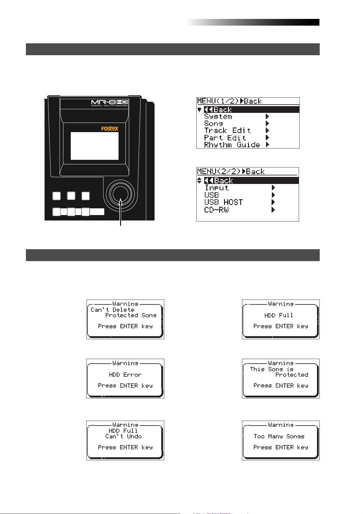
MENU mode screen ....................................................................................................26
Warning message .......................................................................................................26
Basic operations .....................................................................................................................27
About power .........................................................................................................................28
Power connection .......................................................................................................28
About the standby mode ......................................................................28
Turning on the unit ....................................................................................................28
Listening the demo song ....................................................................................................29
Connecting headphones (or monitor speaker system) ........................................29
Playing back the demo song .....................................................................................30
Creating a song for recording ..........................................................................................31
4

MR-8HD/CD Owner’s Manual (Safety instructions/Contents)
Input connection ..................................................................................................................33
Input channel ..............................................................................................................33
INPUT A SEL switch .....................................................................................................33
Recording track combinations and available input channel(s) ..........................34
Recording onto a single track ............................................................................................35
Preparation for recording .........................................................................................35
Starting recording ......................................................................................................36
Playing back the recorded track ...............................................................................36
Undoing recording (undo/redo) .............................................................................36
Overdubbing basics ............................................................................................................37
Preparation for recording .........................................................................................37
Adjusting the recording levels while listening to track 1 .....................................38
Starting recording ......................................................................................................38
Playing back recorded track .....................................................................................38
Undoing recording (undo/redo) .............................................................................38
Recording onto four trac ks simultaneously ....................................................................39
Preparation for recording .........................................................................................39
Starting recording ......................................................................................................40
Playing back recorded tracks ....................................................................................40
Undoing recording (undo/redo) .............................................................................40
Basic mixdown ................................................................................................................. ....41
Mixdown to an analog recorder ...............................................................................41
Mixdown to a digital recorder ..................................................................................42
Advanced playbac k and locates functions .........................................................................43
3 x cueing ..............................................................................................................................44
Playback between LOCA TE A and B points .....................................................................44
Play mode ..............................................................................................................................45
Selecting a play mode ................................................................................................45
Auto play mode ...........................................................................................................46
Auto return mode .......................................................................................................46
Loop mode ...................................................................................................................46
Loop function in auto punch in/out mode ........................................47
Locate function ............................................................................................................... .....48
Time locate ..................................................................................................................48
Locating to the beginning (ABS ZERO) of a song ...............................48
Locating to the recording end point (REC END) of a song ...............48
Locating to the LOCATE A or LOCATE B point ........................................................49
Setting the LOCATE A or LOCATE B point ..........................................49
Locating ...................................................................................................50
Punch in/out .............................................................................................................................51
Punch in/out using the keys on the top panel ..................................................................52
Punch in/out using the foots witch .....................................................................................53
Auto punch in/out .................................................................................................................54
Setting the punch-in and punch-out points ...........................................................54
Rehearsal for auto punch in/out ..............................................................................55
Actual auto punch in/out ..........................................................................................56
5

MR-8HD/CD Owner’s Manual (Safety instructions/Contents)
Using effects ............................................................................................................................57
Using the insert effects .......................................................................................................58
Mic simulation effects ................................................................................................58
Amp simulation effects ..............................................................................................58
Applying external effects ....................................................................................................5 9
Using the reverb or delay ....................................................................................................6 0
Selecting an effect type ..............................................................................................60
Selecting a delay type ................................................................................................60
Adjusting the delay/reverb time .............................................................................61
Adjusting the effect send levels ................................................................................61
Using the mastering effects ...............................................................................................62
Selecting the desired effect type ..............................................................................62
T rack bouncing ................................................................................................................ .......63
Preliminary knowledge .......................................................................................................64
Track bouncing example ...........................................................................................64
Signal flow of track bouncing ...................................................................................65
Bouncing tracks 1 through 4 to trac ks 5/6 ........................................................................66
Rehearsal of track bouncing .....................................................................................66
Actual track bouncing ...............................................................................................67
Checking the bounced signals on tracks 5/6 .........................................................67
Bouncing tracks 1 through 6 to trac ks 7/8 ........................................................................68
Rehearsal of track bouncing .....................................................................................68
Actual track bouncing ...............................................................................................69
Checking the bounced signals on tracks 7/8 .........................................................69
Bouncing tracks 1 through 8 to a new song .....................................................................70
Rehearsal of track bouncing .....................................................................................70
Actual track bouncing ...............................................................................................71
Mixing signals of inputs A through D ................................................................................72
Connecting sound sources to INPUT A through INPUT D ....................................72
[TO STEREO BUSS ON/OFF] key setting ...................................................................72
Panning setting for INPUT A through INPUT D ......................................................73
Bouncing the desired part of a song .................................................................................74
Rhythm guide function ..........................................................................................................75
Using the rhythm guide function .......................................................................................76
Setting the time signature and tempo .....................................................................76
Creating the conductor map ..............................................................................................78
Setting the signature map .........................................................................................78
Editing a time signature event .............................................................80
Deleting an unnecessary time signature event .................................80
Editing the bar offset ..................................................................................................81
Setting the tempo map ...............................................................................................82
Editing a tempo event ...........................................................................84
Deleting an unnecessary tempo event ...............................................84
6

MR-8HD/CD Owner’s Manual (Safety instructions/Contents)
MIDI synchronization .......................................................................................................... ...85
Synchronization using MTC ...............................................................................................86
Connection ..................................................................................................................86
Settings of the MR-8HD/CD and MIDI sequencer ..................................................86
MIDI sync/MTC frame rate settings .........................................................................86
Synchronization using MIDI c lock .....................................................................................87
Connection ..................................................................................................................87
Settings of the MR-8HD/CD and MIDI sequencer ..................................................87
Data export to a personal computer .....................................................................................89
W AV file con version ........................................................................................................... ..90
Enabling the file conversion .....................................................................................90
Procedure of file conversion .....................................................................................90
Exporting data to a personal computer ............................................................................92
Connection to a personal computer ........................................................................92
Notes on exporting a file ............................................................................................92
Exporting a WAV file to a personal computer ........................................................93
Protecting the hard disk ......................................................................................................94
Archiving a song .............................................................................................................. ....95
Song management ............................................................................................................... ..97
Selecting the desired song .................................................................................................98
Editing a song name ........................................................................................................... .99
Deleting an unnecessary song ......................................................................................100
Protecting a song .............................................................................................................101
T rack editing ..........................................................................................................................103
Erasing track data ..............................................................................................................104
Copying/pasting track data ..............................................................................................105
Moving track data ...............................................................................................................107
Exchanging whole track data ...........................................................................................108
Part editing .............................................................................................................................111
Playing back the “part” (Between LOCATE A and LOCATE B) to be edited .............112
Changing an edit point during editing .................................................................112
Editing the part(s) ..............................................................................................................113
Copying/pasting the part(s)-1 ..........................................................................................114
Copying/pasting the part(s)-2 ..........................................................................................116
Copying to the clipboard ........................................................................................116
Pasting clipboard data .............................................................................................117
7

MR-8HD/CD Owner’s Manual (Safety instructions/Contents)
Moving the part(s) .............................................................................................................119
Exchange the parts ............................................................................................................120
Other functions .....................................................................................................................123
Hard disk formatting ..........................................................................................................124
Peak hold time setting .......................................................................................................1 25
Pre-roll/post-roll time setting ...........................................................................................126
Beat resolution mode on/off .............................................................................................127
Phantom power on/off .......................................................................................................128
Initializing the MR-8HD/CD ...............................................................................................130
T roubleshooting ............................................................................................................... ....131
T rouble for recording .........................................................................................................132
T rouble for pla yback ..........................................................................................................133
T rouble for effect ................................................................................................................134
T rouble for USB connection .............................................................................................134
Other troubles .....................................................................................................................135
MR-8HD/CD Specifications ........................................................................................................137
Specifications .....................................................................................................................138
Physical dimensions .........................................................................................................13 9
Block diagram ....................................................................................................................140
MIDI implementation chart ...............................................................................................142
Index ....................................................................................................................................143
Declaration of EC Directive ..............................................................................................144
8

MR-8HD/CD Owner’s Manual (Read this chapter first!)
Read this chapter first!
This chapter describes precautions before using, as well as features and
basic knowledge of the MR-8HD/CD.
To understand the MR-8HD/CD features and basic functions, read this
chapter before using.
9

MR-8HD/CD Owner’s Manual (Read this chapter first!)
Introduction
Thank you very much for purchasing the Fostex MR-8HD/CD digital multitracker.
The MR-8HD/CD is a digital multitracker which can record 8-track audio at 44.1 kHz/16 bits on the
internal 3.5-inch hard disk. Up to four tracks can be recorded simultaneously.
The MR-8HD/CD is also equipped with an 8-channel digital mixer, digital effects including the delay/
reverb, mastering effects and insert effects (simulation effects). It allows you to carry out all the
process for digital multitrack recording including overdubbing, track bouncing and mixdown within
the digital domain, ensuring no loss of sound quality.
You can also create an original audio CD using the internal CD-R/RW drive (or an external CD-R/RW
drive connected to the [USB HOST] port).
MR-8HD/CD main features
• You can record high quality audio to the builtin high performance 3.5-inch hard disk drive
(40GB). You can also edit recorded audio later
without sound deterioration. Up to 99 songs
can be recorded.
• Provides four analog input channels and up to
four tracks can be recorded simultaneously.
Signals of four input channels ([INPUT A]
through [INPUT D]) can be mixed to the stereo
buss (Pre mastering effects).
• You can bounce all eight tracks to a new song,
which is automatically created in the bouncing
process.
• An ASP digital effect processor (delay/reverb)
with the algorithm newly developed by Fostex
is built in, allowing effect processing to tracks 1
through 4 during track bouncing.
In addition, the MR-8HD/CD also provides
insert effects for microphone and amplifier
simulation for coloring sounds.
• The dedicated mastering effects are built in for
the stereo buss, allowing you to process sounds
during track bouncing or final mixdown.
• The adoption of self-illuminated keys allows
intuitive operation.
• Phantom power is built in, allowing direct
connection of condenser microphones.
• The rhythm guide function is provided.
You can make global time signature/tempo
setting for a simple song or create a conductor
map for a more complicate song, and output
the guide click.
• Song data (on mono WAV files on tracks 7 and
8) mastered by the MR-8HD/CD can be
converted to a stereo WAV file easily.
You can export the converted stereo WAV file
to a personal computer and create an audio CD
using the CD burn function of the personal
computer.
• The [DIGITAL OUT] port outputs S/PDIF
format digital signals. You can make mixdown
or digital copy to an external DAT or MD
recorder.
• The whole or a part of track data can be edited
(i.e. copied, pasted, moved, exported,
exchanged and erased).
• The [MIDI OUT] port is provided.
You can synchronize the MR-8HD/CD with
external MIDI devices (MIDI sequencer, etc.)
using MTC or MIDI clock.
• The CD-R/RW drive is built in as standard.
You can create an audio CD (CD-DA), as well as
can export (copy) the mono WAV file converted
from unit's song data to a CD-R/RW disc.
See the supplementary manual “How to use the
CD-R/RW drive” for details.
• The [USB HOST] port is provided for
connecting to an external CD-R/RW drive.
You can burn an audio CD in the CD-DA
format using an external CD-R/RW drive.
See the supplementary manual “How to use the
CD-R/RW drive” for details.
• The 2-mix file playback mode allows you to play
back a stereo WAV file which is used for
creating an audio CD, as well as set CUE points
for dividing file data into individual CD tracks
on the audio CD.
See the supplementary manual “How to use the
CD-R/RW drive” for details.
10
MR-8HD/CD Owner’s Manual (Read this chapter first!)
Precautions before using
About power supply
• Be sure to connect the MR-8HD/CD to the
power supply specified in the specifications
section of this owner's manual. Do not use
an AC outlet of any other voltage.
• Do not connect the MR-8HD/CD to the same
AC outlet to which devices that could
generate noise (such as a large motor or
dimmer), or the devices that consume a large
amount of power (such as an air
conditioning system or large electric heater)
are connected.
• If you use the MR-8HD/CD in an area with a
different power voltage, first consult your
dealer or the nearest Fostex service station.
• The [POWER] switch cannot turn off the
power completely. When this switch is "up",
the MR-8HD/CD enters standby mode (i.e. the
power does not completely turned off).
Therefore, if you do not use the MR-8HD/CD
for a long time, we recommend unplugging
the power cord from the AC outlet.
• It is very dangerous to use a power cord that
is frayed or damage. In such a case, stop
using the MR-8HD/CD immediately and ask
your dealer to repair the cord.
<Important! >
Model name, power requirement, serial
number and other information for the
MR-8HD/CD are shown at the bottom of
the unit.
DIGITAL MULTITRACKER
S
P
E
FOSTEX
100-240V ~
SERIAL NO.
MODEL MR-8HD/CD
16W
50/60Hz
MADE IN CHINA
Precautions upon installing the MR-8HD/CD
• Do not install the MR-8HD/CD in locations
subject to the following:
* Extremely high or low temperature, or
significant changes in temperature.
* Excessive humidity or dust.
* Excessive changes in power supply
voltage.
* Unstable or significantly vibrating or
shaking surfaces.
* Near a strong magnetic field (such as a
TV or speaker).
Notes on repair
• The MR-8HD/CD does not use any parts that
user can repair easily. Contact your dealer
or the nearest Fostex service station to ask
about repairs.
• Use the original packing carton of the
MR-8HD/CD when you transport or send the
MR-8HD/CD to the dealer or Fostex service
station for repair.
If you have discarded the packing carton,
pack the MR-8HD/CD using shock absorbing
materials. Fostex is not responsible for
malfunction or damage due to incomplete
packaging or caused during transportation.
• Because the MR-8HD/CD is a consumer
product, Fostex does not offer on-site service
or provide a loaner unit while your MR-8HD/
CD is under repair.
About copyrights
• It is prohibited by law to use any part of a CD
recording or video images or audio data for
which copyright is possessed by a third party
for commercial purposes such as contents,
broadcasts, sales, or distribution-any purpose
other than for your personal pleasure.
About damages
• Fostex is not responsible for any "direct
damage" or "indirect damage" caused by using
the MR-8HD/CD.
Notes on audio interruption
• If you make recording or editing to a song
many times, audio may be occasionally
interrupted when the song is played back,
due to data fragmentation. Note that this is
not a malfunction.
Note on USB connection with Mac OS
• Before you connect the MR-8HD/CD to a
Macintosh computer, make sure that the OS
is Mac OS X or higher. The MR-8HD/CD
supports only Mac OS X or higher.
If you connect the MR-8HD/CD to a Macintosh
computer with Mac OS lower than "OS X",
song data on the MR-8HD/CD may be
damaged.
11
MR-8HD/CD Owner’s Manual (Read this chapter first!)
The basics of the MR-8HD/CD
This section describes the basics of the MR-8HD/CD you should know before using the MR8HD/CD.
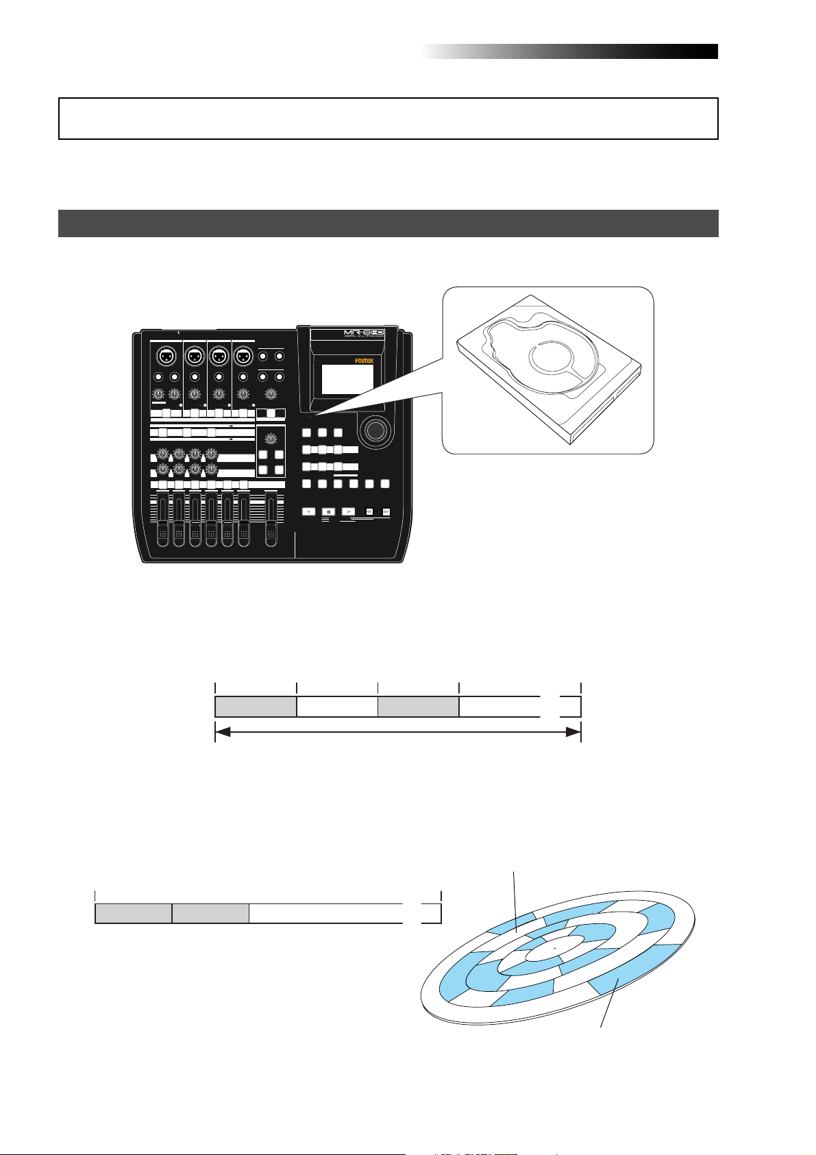
Recording method
The MR-8HD/CD is fitted with a 3.5-inch hard disk drive. Songs are recorded on a hard disk
along with the ABS time (from 00m 00s 000ms to 399m 59s 999ms).
INPUT A SELECT
INPUT A
INPUT B INPUT C INPUT D
BAL
UNBAL
/GUITAR
INSERT
DISTORTION
TRIM
MAX
MIN
LINE MIC LINE MIC LINE MIC LINE MIC
GUITAR
PEAK
ON/
OFF
DYNAMIC CONDENSER TUBE
BRIT STACK
010
LRRL
1
MAX
MIN
BALBAL
BAL
STEREO OUT
L
R
UNBAL
TRIM
PEAK
ON/
ON/
OFF
OFF
MIC
SIMULATION
REVERB / DELAY TIME
INPUT A
SIMULATION
AMP
ROOM
EFFECT SEND
PLATE DELAY
PAN
5/6 MASTER
7/8
PHONES
1
PHONES VOL
POWER
EFFECT
MIN MAX
REC SELECT
2
MAXMIN
HALL
MAX
MIN
TIME BASE
RHYTHM
CONTRAST
SELECT
GUIDE
NEW
1-4 > 5/6 STEREO
7/8 >
1-8 >
SONG
1-6 > 7/8
WAV FILE
NATURAL BRIGHT
LOCATE REC END
LOCATE ABS ZERO
A-B PLAY
BOUNCE
MASTERING
LOCATE
A / IN
B / OUT
PLAYSTOP
ABC1 DEF2 GHI3
POWERFUL
JKL4 MNO5
PQR6 STU7 VWX8 YZ9 +-_0
RECORD
MENU / ENTER
UNDO/REDO
STOREPLAY MODEAUTO PUNCH
REWIND F FWD
3.5-inch hard disk drive
DELETE
UNBAL
UNBAL
TRIM
TRIM
PEAK
PEAK
ON/
OFF
TO STEREO BUSS
60'S COMBO
US METAL
100LR100
100
LR
4
3
2
The ABS time shows the absolute time on a hard disk and you can start recording from any
desired time within the range between 00m 00s 000ms and 399m 59s 999ms ABS time.
The beginning of a song
0m00s000ms
(ABS ZERO) 05m00s000ms 10m00s000ms
Recorded area Recorded areaNon-recorded area Non-recorded area
You can start recording from any desired time within the range
between 00m00s000ms and 399m59s999ms ABS time.
15m00s000ms
(REC END)
399m59s999ms
......
As the MR-8HD/CD does not consume the disk space when no audio is recorded, you can record
audio effectively, while the recordable time for a tape recorder depends on the tape length.
Non recorded area (shown in white)
0m00s000ms
5-minute recording
5-minute recording
Non-recorded area (remain)
399m59s999ms
......
12
Recorded area (shown in gray)
MR-8HD/CD Owner’s Manual (Read this chapter first!)
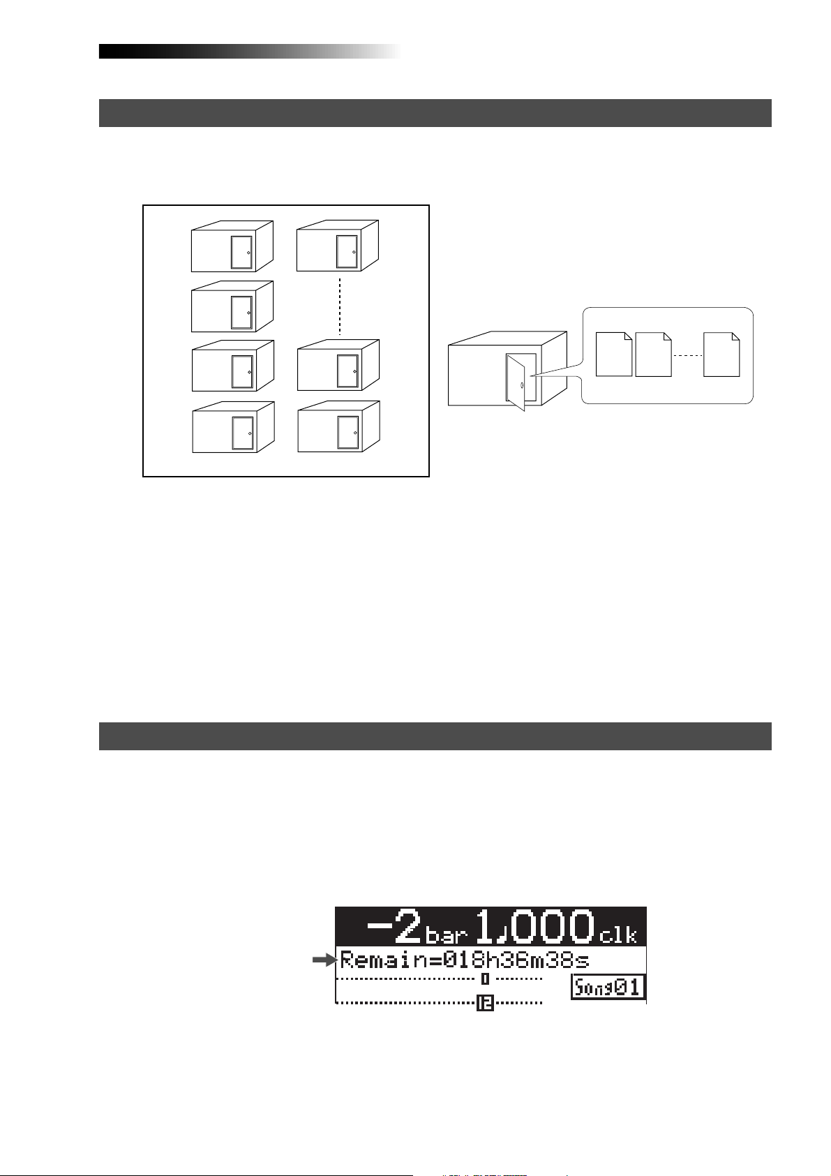
About song
To understand songs, imagine separated rooms as shown below. Each room can be regarded as
a song. With the MR-8HD/CD, you can create up to 99 rooms (songs) on the hard disk (although
the available space may limit the number of songs).
Song01
Song02
Song03
Song04
Song05
Song98
Song99
Recorded track data is stored in a song as mono WAV
files, as shown below.
Track 1
Track 2
Track 8
Song01
WAV files
Each song is independent on a disk and you can record, play back or edit a song without affecting other songs. You can give a desired song name for managing recorded songs (see page 99).
Recorded track data is stored in a song as mono WAV files.
The MR-8HD/CD can convert the two WAV files recorded on tracks 7 and 8 (L and R) to a stereo
WAV file (see page 90).
You can burn converted stereo WAV files to an audio CD by using the internal CD-R/RW drive or
a drive connected to the [USB HOST] port (see the supplementary manual "Using the CD-R/RW
drive"). You can also burn converted stereo WAV files to an audio CD by exporting them to a
personal computer and using the music software application on the personal computer (see
page 92).
Remain (recordable space left on the disk)
"Remain" shows how much time you can further record audio data to the available space left on
the internal hard disk.
As described earlier, the MR-8HD/CD stripes ABS time from 0m 00s 000ms to 399m 59s 999ms
at maximum for each song. However, the remaining time (= available recording time left) depends on the available space on the hard disk in actual use. The remaining time is shown as in
the screen example below during recording or record standby. Note that it shows the remaining
time for recording onto a mono track.
Remain value
A "mono" track means a single track. Therefore, you can calculate the remaining time for recording to more than one track by dividing the displayed time by the number of tracks. Note that the
remaining time shown on the screen is an approximate time.
13
MR-8HD/CD Owner’s Manual (Read this chapter first!)
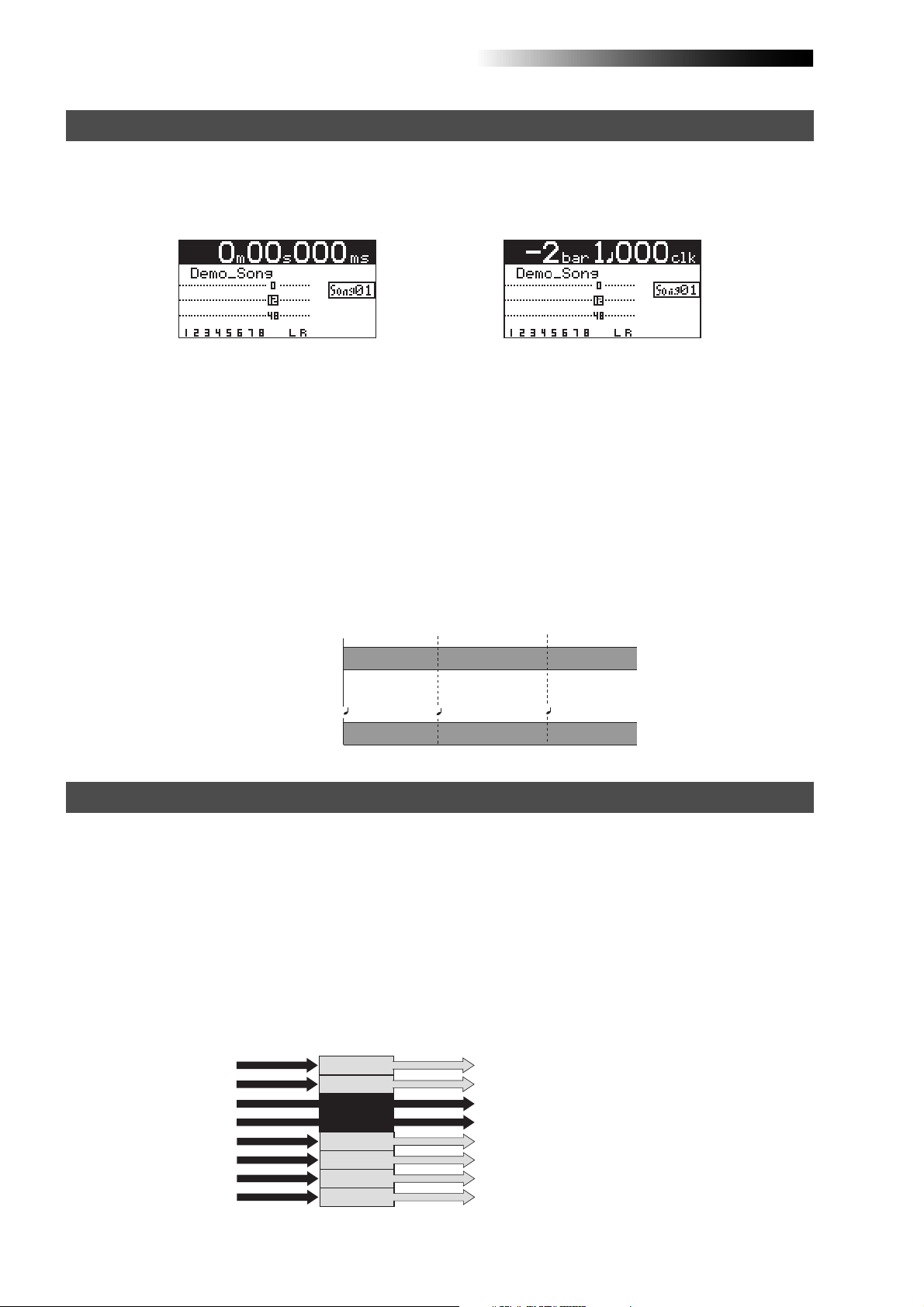
Time base
The term, "time base", is used as the reference of recorder position information.
Using the [TIME BASE SELECT] key, you can select from among two time base modes: ABS time
and bar/beat mode. Each screen example below shows the recorder is located at the beginning of
a song in each time base mode.
<ABS time mode>
<Bar/beat mode>
ABS time mode:
ABS time stands for Absolute time, which is "striped" on the disk when creating a song. It starts from
0m 00s 000ms (=ABS zero, the beginning of a song) and ends by 399m 59s 999ms at maximum.
Bar/beat mode:
The bar/beat/clock information is created according to the internal tempo map.
The ABS zero position is set to "bar -2/beat 1/clk 000" by default (this is called "bar offset").
The MR-8HD/CD determines the bar/beat/clock value in a song in referenced to the bar offset,
as well as the time signature map and tempo map. You can set the bar offset between bar 1 to bar
-8 via the menu mode (see page 81). The figure below shows the relation between two time base
modes.
The beginning of a song
0m00s000ms
(ABS ZERO)
ABS time mode
-2bar 1 000clk
Bar/beat mode
0m03s000ms 0m06s000ms
1bar 1 000clk
3bar 1 000clk
Input monitor and repro monitor
Each of the MR-8HD/CD tracks has two output modes: repro monitor and input monitor.
In the repro monitor mode, the track playback signal is output. So if you want to listen to the
track playback sound, select the repro monitor mode.
In the input monitor mode, the input signal fed to the track is output. So you can check the level
of the input signal to be recorded.
To enter a MR-8HD/CD track to input monitor mode, press the appropriate [REC SELECT] key to
arm the track (i.e. make the track record-ready), then press only the [RECORD] key to enter the
"RECORD READY" mode or press both the [RECORD] and [PLAY] keys simultaneously to start
recording.
Input signals for
recorder tracks
Track 3
Track 4
Output signals from
Track 1
Track 2
READY
READY
Track 5
Track 6
Track 7
Track 8
recorder tracks
Playback signal (repro monitor)
Playback signal (repro monitor)
Input signal (input monitor)
Input signal (input monitor)
Playback signal (repro monitor)
Playback signal (repro monitor)
Playback signal (repro monitor)
Playback signal (repro monitor)
14

MR-8HD/CD Owner’s Manual (Read this chapter first!)
[TRIM] control
You must pay great attention to the [TRIM] control adjustment when recording to the MR-8HD/
CD.
INPUT A
BAL
UNBAL
/GUITAR INSERT
DISTORTION
MIN MAX LINE MIC LINE MIC LINE MIC LINE MIC
GUITAR
TRIM
PEAK
ON
OFF
INPUT B INPUT C INPUT D
UNBAL
TRIM
PEAK
ON
OFF
BALBAL
UNBAL
TRIM
PEAK
ON
OFF
BAL
UNBAL
TRIM
PEAK
ON
OFF
[TRIM] control
PEAK LED
The analog signal received at each input ([INPUT A] through [INPUT D]) is sent to the [TRIM]
control, by which the signal level fed to the A/D converter of the MR-8HD/CD is controlled.
You can check this level by the PEAK indicator. If the level is too high, the PEAK indicator lights,
while you may hear the sound distorted or noisy. This distortion (noise) generated at this stage
cannot be eliminated, therefore, adjust the TRIM control properly so that the PEAK indicator
does not light at the loudest part of the input signal.
Clipping level
Clipping level
Proper level
The level is too high.
15

MR-8HD/CD Owner’s Manual (Read this chapter first!)
16

MR-8HD/CD Owner’s Manual (Names and functions)
Names and functions
This chapter describes the names and functions of the controls, keys,
connectors, etc. on the MR-8HD/CD top panel, side panel and rear panel,
as well as details of the display. See this chapter whenever you want to
know the function of a control, key, etc.
17
MR-8HD/CD Owner’s Manual (Names and functions)
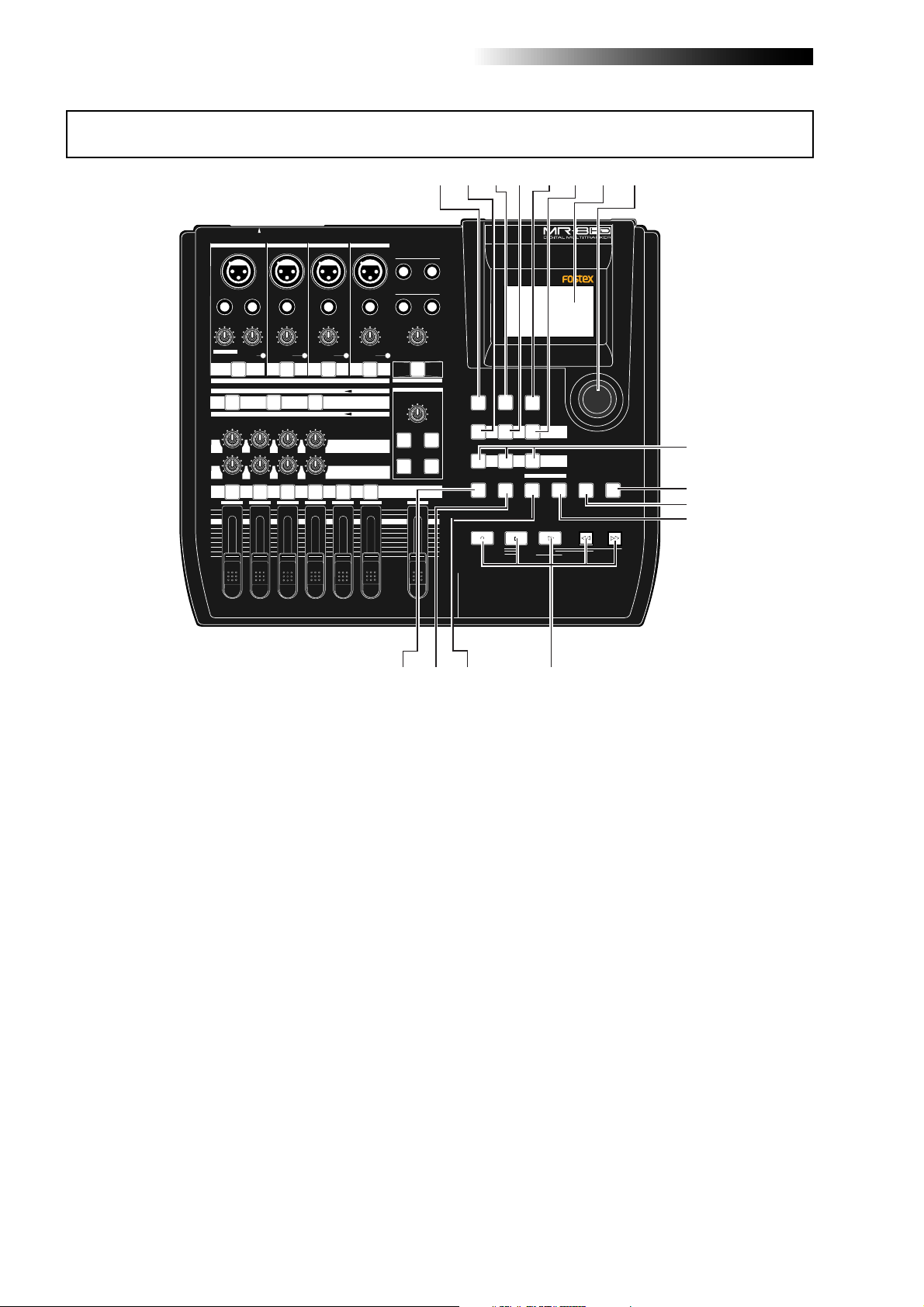
Top panel 1
21
20
19
18
17
16
15
14
1
2
3
INPUT A SELECT
INPUT A
UNBAL
/GUITAR
DISTORTION
MAX
MIN
GUITAR
DYNAMIC CONDENSER TUBE
BRIT STACK
010
1
MAX
MIN
INPUT B INPUT C INPUT D
BAL
INSERT
UNBAL
TRIM
TRIM
LINE MIC LINE MIC LINE MIC LINE MIC
PEAK
PEAK
ON/
OFF
ON/
OFF
TO STEREO BUSS
60'S COMBO
US METAL
100LR100
LRRL
2
LR
4
3
4
5
BALBAL
BAL
UNBAL
UNBAL
TRIM
TRIM
PEAK
PEAK
ON/
OFF
MIC
SIMULATION
INPUT A
SIMULATION
AMP
EFFECT SEND
100
PAN
5/6 MASTER
7/8
ON/
OFF
STEREO OUT
L
PHONES
1
PHONES VOL
POWER
EFFECT
REVERB / DELAY TIME
MIN MAX
ROOM
PLATE DELAY
REC SELECT
67
R
2
MAXMIN
RHYTHM
GUIDE
1-4 > 5/6 STEREO
1-6 > 7/8
HALL
ABC1 DEF2 GHI3
POWERFUL
JKL4 MNO5
PQR6 STU7 VWX8 YZ9 +-_0
MAX
RECORD
MIN
8
TIME BASE
SELECT
NEW
1-8 >
SONG
NATURAL BRIGHT
CONTRAST
7/8 >
WAV FILE
LOCATE
A / IN
LOCATE REC END
LOCATE ABS ZERO
A-B PLAY
BOUNCE
MASTERING
PLAYSTOP
B / OUT
MENU / ENTER
UNDO/REDO
STOREPLAY MODEAUTO PUNCH
DELETE
REWIND F FWD
9
10
11
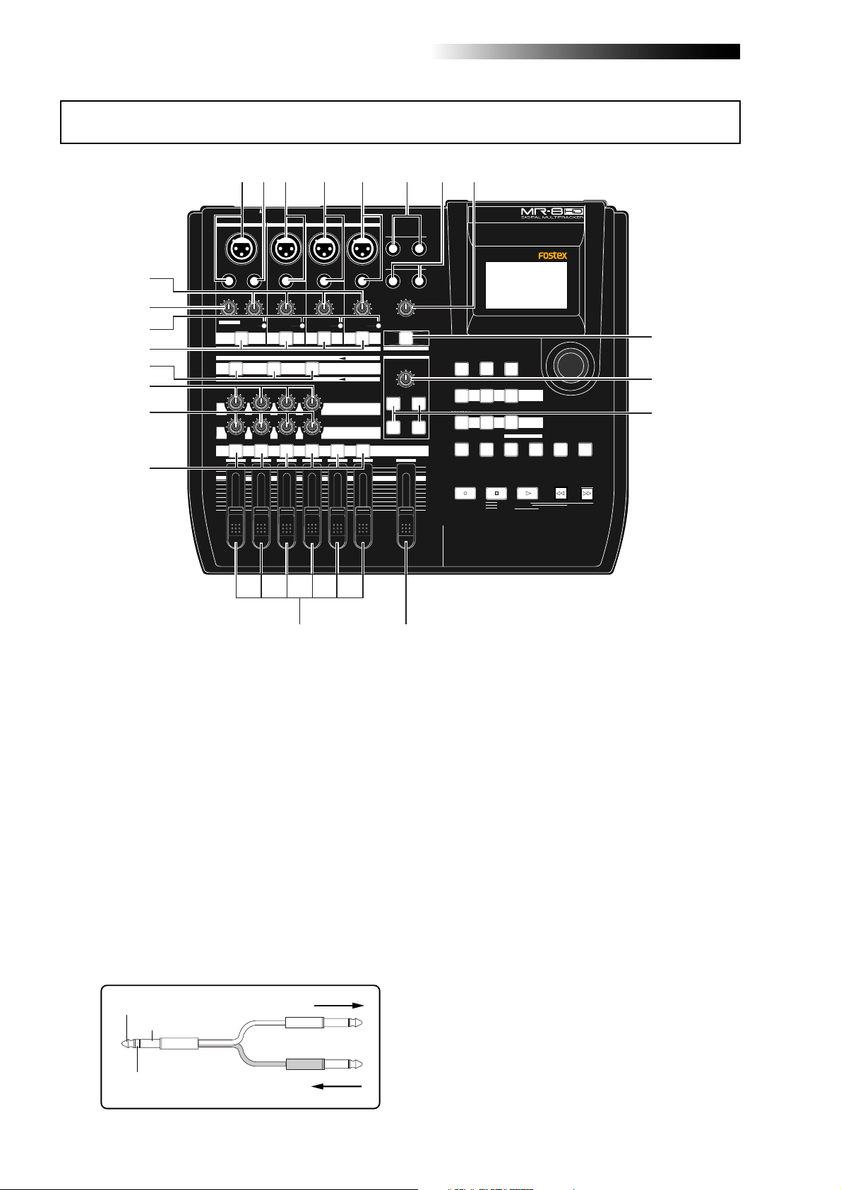
1. [INPUT A] input connectors
(XLR connector and phone jack)
Both the [BAL] XLR connector and [UNBAL/
GUITAR] phone jack are provided. You can
connect a guitar, microphone, keyboard, etc.
If you connect sources to both the XLR connector and phone jack, the phone input takes
priority. When using the [INPUT A] section,
select the [INPUT A SELECT] switch on the
rear panel appropriately according to your
usage (see page 33).
2. [INSERT] connector (TRS phone jack)
Connects an external effect processor (typically, a compressor/limiter, etc.).
For connection between the MR-8HD/CD and
the effect processor, use a Y-cable as shown
below (see page 59).
TIP: SEND
GND
RING: RETURN
To the effect input.
From the effect output.
1213
3. [INPUT B] input connectors
(XLR connector and phone jack)
You can connect a microphone, keyboard,
etc. to the [INPUT B] input.
Both the [BAL] XLR connector and [UNBAL]
phone jack are provided so you can use the
appropriate connector according to the
sound source.
If you connect sources to both the XLR connector and phone jack, the phone input takes
priority (see page 33).
4. [INPUT C] input connectors
(XLR connector and phone jack)
You can connect a microphone, keyboard,
etc. to the [INPUT C] input.
Both the [BAL] XLR connector and [UNBAL]
phone jack are provided so you can use the
appropriate connector according to the
sound source.
If you connect sources to both the XLR connector and phone jack, the phone input takes
priority (see page 33).
18

MR-8HD/CD Owner’s Manual (Names and functions)
5. [INPUT D] input connectors
(XLR connector and phone jack)
You can connect a microphone, keyboard,
etc. to the [INPUT D] input.
Both the [BAL] XLR connector and [UNBAL]
phone jack are provided so you can use the
appropriate connector according to the
sound source. If you connect sources to both
the XLR connector and phone jack, the phone
input takes priority (see page 33).
6. [STEREO OUT] jacks (L, R)
These jacks output the stereo (L and R) buss
signals. Connect these jacks to the monitoring equipment or master recorder (see pages
29 and 41).
7. [PHONES] jacks (1, 2)
Two jacks (1 and 2) are provided. You can
use two pairs of stereo headphones with the
MR-8HD/CD (see page 29).
8. [PHONES VOL] control
Adjusts the headphone output level (see
page 30).
14. [REC SELECT] keys
Used to select the recording track(s). You can
record onto up to four tracks simultaneously.
Pressing a key arms or unarms the corresponding track(s).
Tracks 5/6 or 7/8 are armed or unarmed
simultaneously (see pages 34 through 42).
15. [PAN] contr ols
Control panning for tracks 1 through 4.
16. [EFFECT SEND] controls
Control the amount of signals from tracks 1
through 4 sent to the internal effect (reverb
or delay) (see page 61).
17. Insert effect selection keys
Used to select the insert effect (mic simulation or amp simulation) for the signal from
the [INPUT A] jack.
When setting the [INPUT A SELECT] switch
on the rear panel to "MIC/LINE", you can use
the mic simulation effect. When setting the
switch to "GTR/DIST", you can use the guitar
amp simulation effect (see page 58).
9. [PO WER] switch
Switches between standby mode and power
on (see page 28). To turn off the power when
the power is on, press and hold down the
[POWER] switch for a few seconds.
<Note>:
power completely. When this switch is "up",
the MR-8HD/CD enters standby mode (i.e.
the power does not completely turned off).
Therefore, if you do not use the MR-8HD/
CD for a long time, we recommend unplugging the power cord from the AC outlet.
This switch cannot turn off the
10. [REVERB/DELAY TIME] control
This control adjusts the reverb time or delay time. When you select "ROOM", "HALL"
or "PLA TE" for the effect type, it adjusts the
reverb time.When you select "DELAY", it
adjusts the delay time. (See page 61.)
11. [EFFECT] keys
These keys are used to select the effect type.
You can select from three reverb types
(ROOM, HALL and PLATE) and a delay
(DELAY). The selected key is lit (see page 60).
12. [MASTER] fader
Adjusts the stereo (L and R) buss output level
(see pages 30 through 39).
18. [TO STEREO BUSS ON/OFF] keys
Each key selects whether or not sending the
corresponding input signal to the stereo L/
R busses (see page 72). Each press of the
key alternates ON and OFF. When ON, the
key illuminates in green. When OFF, it is
unlit. When the corresponding input is assigned to a recording track, the key flashes
in green.
A long press of the key enters the input menu
of the MENU mode, in which you can set
phantom power on/off, panning, etc. (see
page 128).
19. [PEAK] indicators
Each indicator lights when the input signal
is overloaded (see page 15). You should adjust the input gain using the [TRIM] control
so that the [PEAK] indicator does not light.
20. [DISTORTION] control
Controls the amount of the distortion effect
for a guitar connected to the [XLR] connector or [UNBAL/GUITAR] jack (phone type) on
the [INPUT A] channel.
This control is effective only when the [IN-
PUT A SELECT] switch is set to "GTR/DIST"
(see pages 35 through 40).
13. Track fader s
Each fader adjusts the track playback level.
Each of track faders 5/6 and 7/8 controls
the stereo signal (see pages 30 through 39).
21. [TRIM] controls
Each control adjusts the input gain of the
corresponding input channel (see page 15,
and 35 through 40).
19
MR-8HD/CD Owner’s Manual (Names and functions)
Top panel 2
INPUT A SELECT
INPUT A
UNBAL
/GUITAR
DISTORTION
MAX
MIN
GUITAR
DYNAMIC CONDENSER TUBE
BRIT STACK
010
1
MAX
MIN
INPUT B INPUT C INPUT D
BAL
INSERT
UNBAL
TRIM
TRIM
LINE MIC LINE MIC LINE MIC LINE MIC
PEAK
PEAK
ON/
OFF
ON/
OFF
TO STEREO BUSS
60'S COMBO
US METAL
100LR100
LRRL
2
LR
4
3
BALBAL
BAL
UNBAL
UNBAL
TRIM
TRIM
PEAK
PEAK
ON/
OFF
MIC
SIMULATION
INPUT A
SIMULATION
AMP
EFFECT SEND
100
PAN
5/6 MASTER
7/8
ON/
OFF
STEREO OUT
L
PHONES
1
PHONES VOL
MAXMIN
POWER
EFFECT
REVERB / DELAY TIME
MIN MAX
ROOM
HALL
PLATE DELAY
REC SELECT
22
R
2
MAX
MIN
24
23
RHYTHM
GUIDE
1-4 > 5/6 STEREO
1-6 > 7/8
ABC1 DEF2 GHI3
POWERFUL
JKL4 MNO5
PQR6 STU7 VWX8 YZ9 +-_0
RECORD
25 26 27
TIME BASE
CONTRAST
SELECT
NEW
7/8 >
1-8 >
SONG
WAV FILE
NATURAL BRIGHT
LOCATE
A / IN
LOCATE REC END
LOCATE ABS ZERO
A-B PLAY
BOUNCE
MASTERING
B / OUT
PLAYSTOP
28
MENU / ENTER
UNDO/REDO
STOREPLAY MODEAUTO PUNCH
DELETE
REWIND F FWD
29
30
31
32
33
37
22. [RHYTHM GUIDE] key
Switches on/off of the rhythm guide function (see page 76). Each press of the switch
alternates on and off. A long press of the
key enters the rhythm guide menu, in which
you can set the rhythm guide parameters
(see page 76).
23. [BOUNCE 1-4 > 5/6, 1-6 > 7/8] / A B C 1 key
Selects the bounce mode (see pages 66 and
68).
In the menu mode, this key is used for character entry of A, B, C, a, b, c and 1 (see pages
32 and 99).
24. [TIME BASE SEL] key
Selects the time base shown on the display
(see page 24). Each press of the key switch
between "time" and "bar/beat".
25. [BOUNCE 1-8 > NEW SONG] / D E F 2 key
Selects the bounce mode (see page 70).
In the menu mode, this key is used for character entry of D, E, F, d, e, f and 2 (see pages
32 and 99).
36
35
34
26. [CONTRAST] key
By rotating the [MENU/ENTER] knob while
holding down this key, you can adjust the
display contrast (see page 25).
27. [7/8 > STEREO WAV FILE] / G H I 3 key
This key is used when converting a mono
WAV file recorded on tracks 7/8 to a stereo
WAV file (see page 90). A converted stereo
WAV file can be exported to a USB-connected
personal computer (see page 92), or can be
burned to an audio CD using the internal
CD-R/RW drive or an external CD-R/RW
drive (see the supplementary manual "How
to use the CD-R/RW drive").
In the menu mode, this key is used for character entry of G, H, I, g, h, i and 3 (see pages
32 and 99).
28. LCD display
This 132 x 64 dot LCD display shows various information (see page 24).
29. [MENU/ENTER] rotary / push knob
Pressing this knob enters the menu mode.
In the menu mode, rotating this knob selects the item or numeric value, while pressing this knob confirm the setting/selection.
20

MR-8HD/CD Owner’s Manual (Names and functions)
30. [MASTERING] keys
(POWERFUL / NATURAL / BRIGHT)
Used to select the desired mastering effect
during track bounce or mixdown. You can
select from three effect types by pressing an
appropriate key (see page 62).
In the menu mode, the [POWERFUL] key is
used for character entry of J, K, L, j, k, l and
4, while the [NA TURAL] key is used for character entry of M, N, O, m, n, o and 5 (see
pages 32 and 99).
31. [UNDO/REDO] / [DELETE] key
Used to undo or redo recording or editing
(see pages 36, 38, 40).
Each press of the key alternates "undo" and
"redo". In the menu mode, this key is used
for deleting a character (see pages 32 and
99).
32. [STORE] / + - _ 0 key
Stores the current recorder position (time
data) as the LOCATE A/IN or LOCATE B/OUT
point (see pages 49 and 54).
In the "2-mix file playback" mode, pressing this
key sets a CUE point to the current stereo
WAV file (see the supplementary manual
"How to use the CD-R/RW drive").
In the menu mode, this key is used for character entry of +, -, _ and 0 (see pages 32 and
99).
33. [LOCATE B/OUT] / Y Z 9 key
Pressing this key while holding down the
[STORE] key sets the LOCATE B point (or
punch out point) (see page 49 and 54).
In the menu mode, this key is used for character entry of Y, Z, y, z and 9 (see pages 32
and 99).
34. Transport keys
[PLAY] key
Starts playback of the recorder.
Pressing this key while holding down the
[RECORD] key starts recording of the armed
(record-ready) track(s).
Pressing this key during recording exits recording.
[STOP] key
Stops the recorder.
By pressing the [PLA Y], [REWIND] or [F FWD ]
key while holding down the [STOP] key, you
can locate to a specific point or repeat playback as below.
• [STOP] + [PLAY] (A-B PLA Y)
Repeats playback between the LOCATE A and
LOCATE B points (see page 44).
• [STOP] + [REWIND] (LOCATE ABS ZERO)
Locates to the beginning (ABS ZERO) of the
current song (see page 48).
• [STOP] + [F FWD] (LOCATE REC END)
Locates to the recording end of the current
song (REC END) (see page 48).
[RECORD] key
Pressing the [PLA Y] key while holding down
the [RECORD] key starts recording of the
armed (record-ready) track(s).
By pressing only the [RECORD] key when any
track(s) is armed (in record-ready), the input signal(s) of the armed track(s) can be
monitored (i.e. input monitor mode). (see
pages 35 through 40).
[F FWD] key
Pressing this key fast forwards the recorder.
During playback, pressing this key starts 3 x
cueing (see page 44).
While holding down the [STOP] key, pressing this key locates to the recording end of
the current song (REC END) (see page 48).
[REWIND] key
Pressing this key rewinds the recorder.
During playback, pressing this key starts 3 x
reverse cueing (see page 44).
While holding down the [STOP] key, pressing this key locates to the beginning (ABS
ZERO) of the current song (see page 48).
This key is also used to go up the menu
screen layer while a menu screen is displayed.
35. [LOCATE A/IN] / V W X 8 key
Pressing this key while holding down the
[STORE] key sets the LOCATE A point (or
punch in point) (see page 49 and 54).
In the menu mode, this key is used for character entry of V, W, X, v, w, x and 8 (see pages
32 and 99).
36. [PLAY MODE] / S T U 7 key
Selects a play mode. You can select from
among normal, auto play, auto return and
loop (see page 45).
In the menu mode, this key is used for character entry of S, T, U, s, t, u and 7 (see pages
32 and 99).
37. [AUTO PUNCH] / P Q R 6 key
Turns on or off the auto punch mode (see
page 55).
In the menu mode, this key is used for character entry of P, Q, R, p, q, r and 6 (see pages
32 and 99).
21
MR-8HD/CD Owner’s Manual (Names and functions)
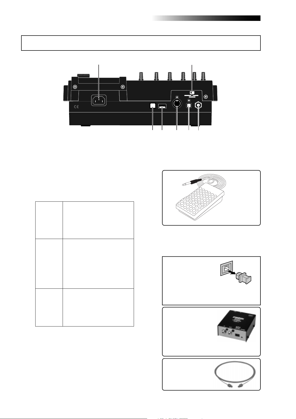
Rear panel
1
1. [AC IN] connector
Connect the supplied power cord to this connector (see page 28).
2. [INPUT A SELECT] switch
This switch must be set appropriately according to the input source of the [INPUT A] channel (see page 33).
Either of the [BAL] XLR and
[UNBAL/GUITAR] phone connec-
MIC/LINE
GTR DIST
GTR CLEAN
tors can be used. Set the switch to
this position when the source is an
external microphone or line level
source.
Either of the [BAL] XLR and
[UNBAL/GUITAR] phone connectors can be used. You can adjust
the input level and distortion using
the [TRIM] and [DISTORTION]
controls respectively . You can also
use the amp simulation insert effect.
Either of the [BAL] XLR and
[UNBAL/GUITAR] phone connectors can be used. You can adjust
the input level using the [TRIM]
control. You can also use the amp
simulation insert effect.
2
INPUT A SEL
GTR CLEAN
MIC/LINE
GTR DIST
USB USB HOSTAC-IN
7
DIGITAL
OUT FOOT SWMIDI OUT
56
34
3. [FOOT SW] jac k (TRS phone jac k)
Used to connect with an unlatched-type
footswitch (see page 53).
unlatched-type footswitch
4. [DIGITAL OUT] connector
(Toslink optical connector)
Used to connect with an external digital device using an optical cable (see page 42).
<Note>:
The dust protec-
tion cap is inserted to
DIGITAL OUT
the [
nector when the unit is
shipped.
Remove the cap when you use this connector. If you do not use this connector, attach
the dust protection cap.
If you need to connect the
unit to a digital device which
only provides a coaxial type
digital connector (typically,
an RCA pin jack), use the
Fostex COP-1/96k coaxialoptical converter (shown
right).
] con-
Model COP-1/96k
22
Use an optical digital
cable with Toslink plugs
on both ends.
MR-8HD/CD Owner’s Manual (Names and functions)
1
5. [MIDI OUT] jack (DIN 5-pin connector)
Used to connect to a MIDI IN jack of an external MIDI device (such as a MIDI sequencer) (see page 86).
6. [USB HOST] connector (USB A type)
Used to connect to an external CD-R/RW
drive for creating an audio CD (CD-DA). See
the supplementary manual "How to use the
CD-R/RW drive" for details.
<Caution>:
computer to the [
Do not connect your personal
USB HOST
] port.
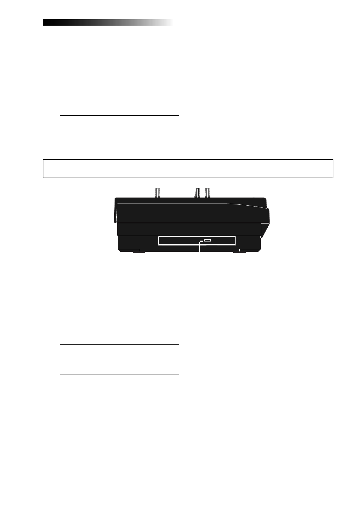
Side panel
7. [USB] port (USB B type)
Used to connect with a personal computer
using a standard USB cable for song file data
transfer between the MR-8HD/CD and the
personal computer (see page 92).
1. Internal CD-R/RW drive
Used to create an original audio CD by burning converted stereo WAV files to a CD-R/
RW disc, or used to record a single mono
WAV file converted from track data on the
HDD to a CD-R/RW disc (see the supplementary manual "How to use the CD-R/RW drive"
for details).
<Caution>:
ROM logo on the front of the CD-R/RW drive
tray, it does not support DVD ROM discs.
Only CD-R/RW discs can be used.
Although you can see the DVD-
23
MR-8HD/CD Owner’s Manual (Names and functions)
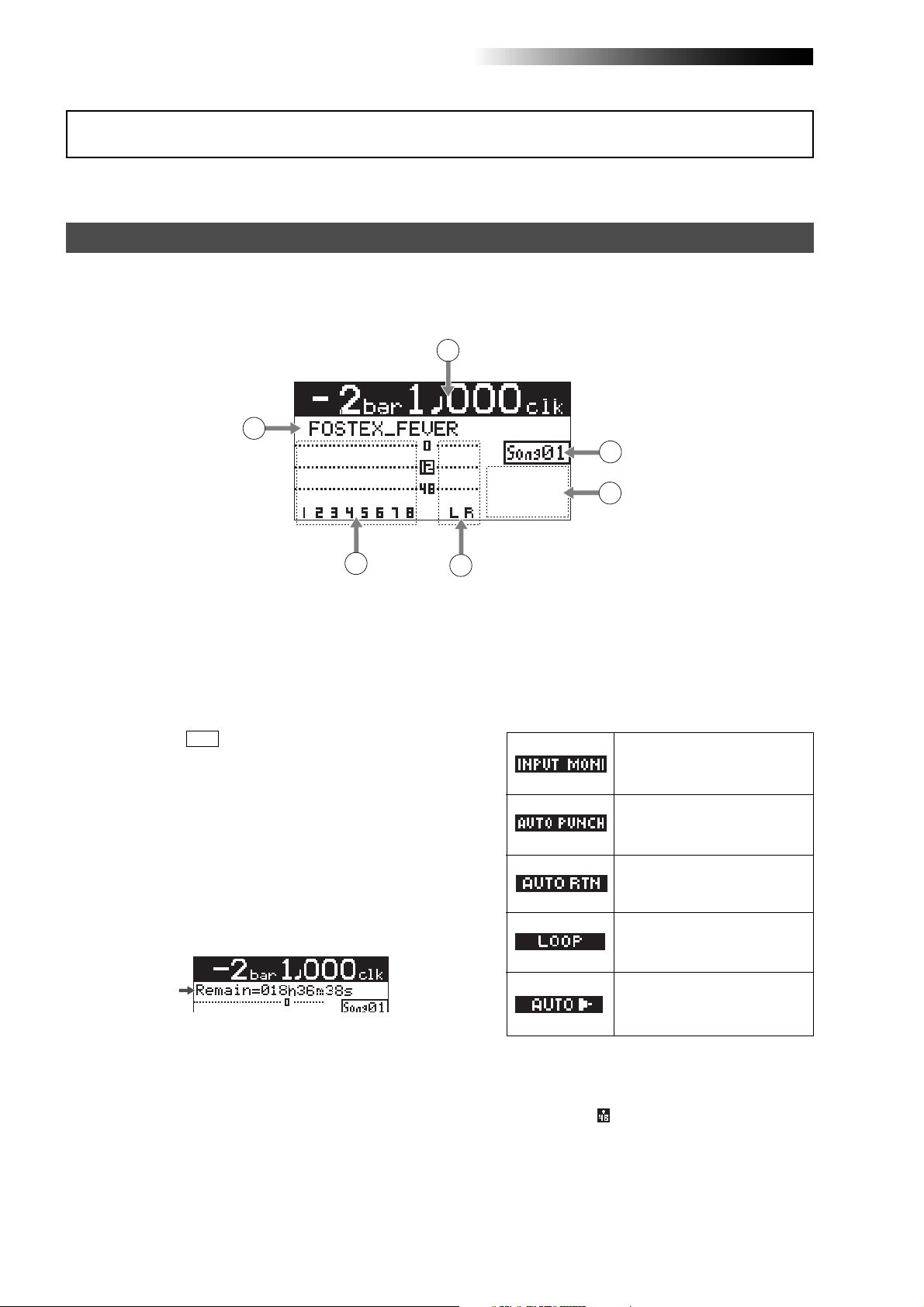
LCD display
The following describes details about the LCD display, including screen contents and operation.
Home screen
When turning on the MR-8HD/CD, the display shows the startup screen (showing the startup status of the
MR-8HD/CD), followed by the "Home" screen, which is similar to the one below. In this condition, the
previously loaded song is loaded and the recorder is located at the beginning of the song.
The home screen provides the following information.
1
2
6
5
1. Time counter display
Time information of the current recorder position is shown in ABS or bar/beat mode (by
default, bar/beat). Using the [TIME BASE SE-
LECT] key, you can select a desired time base
mode. When the recorder is moving (playing
back, fast forwarding, etc.), the appropriate
icon is also shown. While the hard disk drive is
in access, " ACC " lights up.
2. Character display
Normally, the name of the song currently
loaded is shown (up 16 characters can be
shown at a time).
It also shows following information.
• A name of the operation mode currently
being executed (such as "BOUNCE 1-6->7/8).
• A (not-so-serious) warning message
• The "Remain" time when at least one track is
record-armed (i.e. At least one of the
[REC SELECT] keys is active).
The remain time shows how much time you
can further record audio data onto a mono
track using the available space left on the hard
disk.
3. Track level displa y
The recording or playback levels of tracks 1
through 8 are shown. When a track is record
armed, the track number indication changes
to the source input channel (any of A, B, C and
D).
3
4
4. Stereo buss (L and R) level displa y
During recording or playback, the output levels of the L/R stereo buss are shown.
5. Song status display
Lights up the following status icons when the
appropriate modes (functions) are active.
At least one of the tracks is in the
input monitor mode (see pages
36, 38 and 40).
The auto punch mode is active
(see page 55).
The auto return mode is active
(see page 45).
The loop mode is active (see page
45).
The auto play mode is active (see
page 45).
6. Song number display
Shows the song number of the song currently
loaded. Also, "
is on.
" is lit when the phantom power
24

MR-8HD/CD Owner’s Manual (Names and functions)
Selecting a time base mode
When the display shows the home screen, pressing the [TIME BASE SELECT] key switches the time base
mode between ABS and bar/beat.
Example of bar/beat display
RHYTHM
TIME BASE
GUIDE
SELECT
CONTRAST
1-4 > 5/6 STEREO
1-6 > 7/8
[TIME BASE SELECT] key
NEW
1-8 >
7/8 >
SONG
ABC1 DEF2 GHI3
WAV FILE
BOUNCE
MENU/ENTER
Example of ABS display
Adjusting the display contrast
You can adjust the display contrast by rotating the [MENU/ENTER] knob while holding down the [CONTRAST] key. Rotating the dial clockwise heightens the contrast, while rotating it counterclockwise lowers
the contrast.
<High contrast>
RHYTHM
TIME BASE
GUIDE
SELECT
CONTRAST
1-4 > 5/6 STEREO
1-6 > 7/8
[CONTRAST] key
NEW
1-8 >
7/8 >
SONG
ABC1 DEF2 GHI3
WAV FILE
BOUNCE
MENU/ENTER
[MENU/ENTER] knob
While pressing down the [CONTRAST] key, the display shows "CONTRAST -> DIAL".
<Low contrast>
25
MR-8HD/CD Owner’s Manual (Names and functions)
MENU screen
Pressing the [MENU/ENTER] knob while the recorder is stopped enters the menu mode and brings up the
menu screen.
In the menu mode, you can make setting or editing via the appropriate screen. The top menu screen has
two pages, in which you can select the desired menu by rotating the [MENU/ENTER] knob.
<First page>
TIME BASE
RHYTHM
SELECT
GUIDE
CONTRAST
1-4 > 5/6 STEREO
1-6 > 7/8
ABC1 DEF2 GHI3
NEW
7/8 >
1-8 >
SONG
WAV FILE
BOUNCE
MENU/ENTER
[MENU/ENTER] knob
<Second page>
Warning message
If a serious problem happens to the MR-8HD/CD during operation, an appropriate warning message is
shown on the display. Most warning messages are being shown until the [MENU/ENTER] knob is pressed.
Note that there are also not-so-serious warning messages besides the following.
This message is shown
when you are going to
delete a song which is
protected.
This message is shown
when the hard disk
drive has a problem.
During recording, this
message is shown if
there is no more space
left on the hard disk for
recording.
This message is shown
when you are going to
make recording or editing to a song which is
protected.
This message is shown
when you are going to
edit a track or part but
there is not enough
space on the hard disk
for executing the undo
function.
This message is shown
when you are going to
create a new song
while 99 songs exist on
the hard disk.
26

MR-8HD/CD Owner’s Manual (Basic operations)
Basic operations
This chapter describes power connection, power on/off, demo song playback, etc., as well as basic multitrack recording.
If it is the first time for you to use a Multitracker, read this chapter
carefully first so that you are familiar with the MR-8HD/CD basic operations, then read other sections which describe advanced operations.
27
MR-8HD/CD Owner’s Manual (Basic operations)
About power
The MR-8HD/CD operates by AC power. Before you start using the MR-8HD/CD, you must connect the supplied power cord.
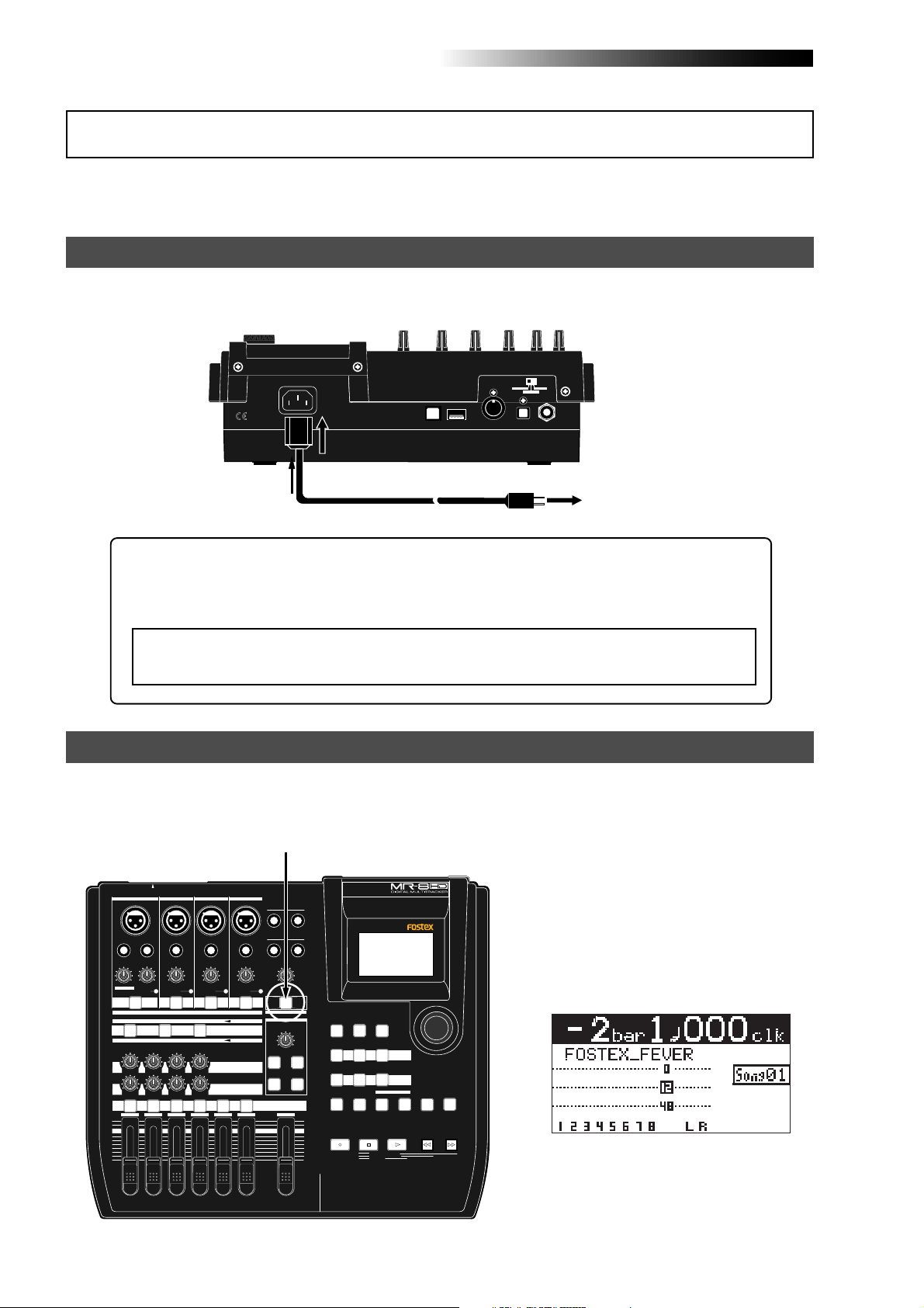
Power connection
Connect between the [AC IN] connector on the MR-8HD/CD rear panel and an AC outlet using the
supplied power cord. The MR-8HD/CD enters the standby mode when the power cord is connected.
INPUT A SEL
GTR CLEAN
MIC/LINE
GTR DIST
USB USB HOSTAC-IN
DIGITAL
OUT FOOT SWMIDI OUT
[AC IN] connector
AC outlet
Supplied power cord
About the standby mode
The standby mode is the condition when the power cord is connected and the [POWER]
switch is set to OFF. In the standby mode, a small amount of power is consumed and the
indicator of the [POWER] switch flashes slowly.
<Note>:
When you do not operate the MR-8HD/CD for a long period of time, we recom-
mend disconnecting the power cord.
Turning on the unit
You can turn on or off the MR-8HD/CD power using the [POWER] switch (pointed by an arrow below).
To turn off the power, press and hold down the [POWER] switch for a few seconds.
When you press the [POWER] switch to
turn on the power for the first time, the
MR-8HD/CD starts up and the display
shows the screen as below (note that it
takes some time until the screen as below is shown).
This screen shows that the demo song is
loaded and stopped at the beginning (ABS
0) of the song named "FOSTEX_FEVER".
Follow the procedure described on the
next page to play back the demo song.
INPUT A SELECT
INPUT A
INPUT B INPUT C INPUT D
BAL
UNBAL
/GUITAR
INSERT
UNBAL
TRIM
DISTORTION
MIN
GUITAR
DYNAMIC CONDENSER TUBE
BRIT STACK
010
MAX
MIN
TRIM
MAX
LINE MIC LINE MIC LINE MIC LINE MIC
PEAK
PEAK
ON/
ON/
OFF
OFF
TO STEREO BUSS
60'S COMBO
US METAL
100LR100
LR
LRRL
3
2
1
[POWER] switch
BALBAL
BAL
UNBAL
UNBAL
TRIM
TRIM
PEAK
PEAK
ON/
ON/
OFF
OFF
MIC
SIMULATION
INPUT A
SIMULATION
AMP
EFFECT SEND
100
PAN
4
5/6 MASTER
7/8
STEREO OUT
L
PHONES
1
PHONES VOL
MAXMIN
POWER
EFFECT
REVERB / DELAY TIME
MIN MAX
ROOM
PLATE DELAY
REC SELECT
R
2
RHYTHM
GUIDE
1-4 > 5/6 STEREO
1-6 > 7/8
HALL
ABC1 DEF2 GHI3
POWERFUL
JKL4 MNO5
PQR6 STU7 VWX8 YZ9 +-_0
MAX
RECORD
MIN
TIME BASE
SELECT
NEW
1-8 >
SONG
NATURAL BRIGHT
LOCATE REC END
LOCATE ABS ZERO
A-B PLAY
CONTRAST
7/8 >
A / IN
WAV FILE
LOCATE
BOUNCE
MASTERING
PLAYSTOP
B / OUT
MENU / ENTER
UNDO/REDO
STOREPLAY MODEAUTO PUNCH
DELETE
REWIND F FWD
28
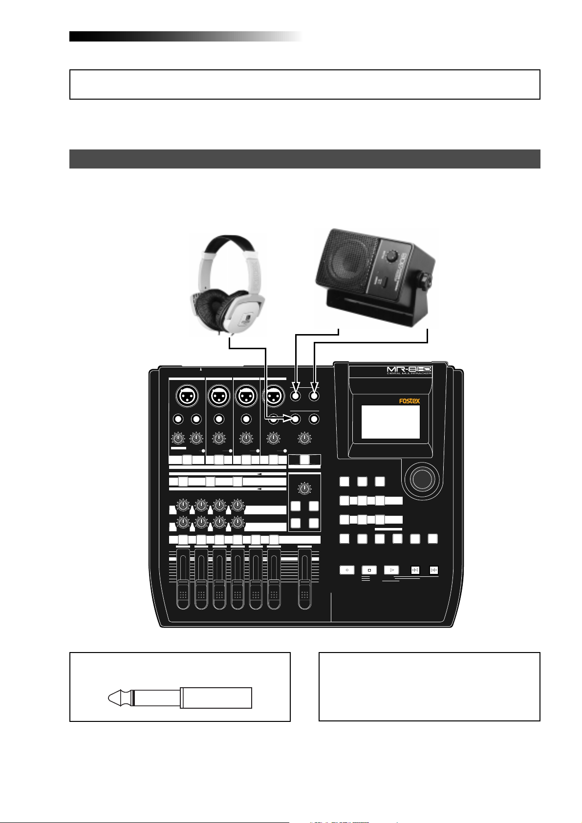
MR-8HD/CD Owner’s Manual (Basic operations)
Listening the demo song
A demo song is pre-recorded on the hard disk of the MR-8HD/CD when shipped.
Before you make recording, let's listen to the demo song via headphones (or a monitor speaker).
Connecting headphones (or a monitor speaker system)
Connect headphones to either of the two [PHONES] jacks of the MR-8HD/CD. Both jacks feed the same
signal so you may connect headphones whichever you like.
If you have a powered monitor speaker, you may connect it to the [STEREO OUT] L or R jacks of the
MR-8HD/CD.
Powered monitor
speaker
Headphones
INPUT A SELECT
INPUT A
UNBAL
/GUITAR
DISTORTION
MAX
MIN
GUITAR
DYNAMIC CONDENSER TUBE
BRIT STACK
010
1
MAX
MIN
INPUT B INPUT C INPUT D
BAL
INSERT
UNBAL
TRIM
TRIM
LINE MIC LINE MIC LINE MIC LINE MIC
PEAK
PEAK
ON/
OFF
LRRL
ON/
OFF
TO STEREO BUSS
US METAL
100LR100
3
2
BALBAL
UNBAL
TRIM
PEAK
ON/
OFF
60'S COMBO
100
LR
4
5/6 MASTER
UNBAL
TRIM
PEAK
MIC
SIMULATION
INPUT A
SIMULATION
AMP
EFFECT SEND
PAN
BAL
7/8
ON/
OFF
STEREO OUT
L
PHONES
1
PHONES VOL
MAXMIN
POWER
EFFECT
REVERB / DELAY TIME
MIN MAX
ROOM
HALL
PLATE DELAY
REC SELECT
R
2
RHYTHM
GUIDE
1-4 > 5/6 STEREO
1-6 > 7/8
ABC1 DEF2 GHI3
POWERFUL
JKL4 MNO5
PQR6 STU7 VWX8 YZ9 +-_0
MAX
RECORD
MIN
TIME BASE
CONTRAST
SELECT
NEW
1-8 >
7/8 >
SONG
NATURAL BRIGHT
LOCATE REC END
LOCATE ABS ZERO
A-B PLAY
A / IN
WAV FILE
MASTERING
LOCATE
BOUNCE
PLAYSTOP
B / OUT
MENU / ENTER
UNDO/REDO
STOREPLAY MODEAUTO PUNCH
DELETE
REWIND F FWD
<Note>:
[
STEREO OUT
You can plug a 1/4" phone plug to the
] L or R jack.
29
<Note>:
When you connect a powered monitor
speaker to the unit, turn down the volume of the
powered monitor speaker to minimum before you
turn on the MR-8HD/CD and the powered monitor speaker.
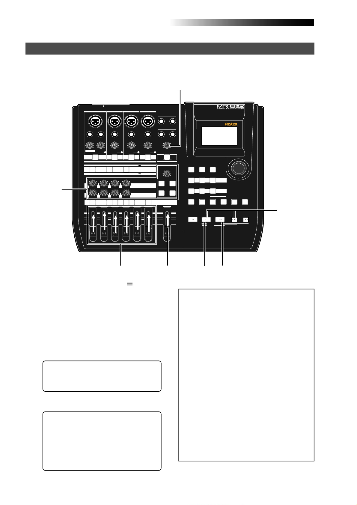
MR-8HD/CD Owner’s Manual (Basic operations)
Playing back the demo song
In the demo song, approximately 1-minute audio is recorded on all eight tracks. Follow the procedure
below for listening to the demo song. In the following procedure, it is assumed that the MR-8HD/CD
is turned on and a pair of headphones (or a monitor speaker system) is connected.
3
INPUT A SELECT
INPUT A
INPUT B INPUT C INPUT D
BAL
BALBAL
BAL
STEREO OUT
L
R
Hint-1
UNBAL
/GUITAR
INSERT
UNBAL
TRIM
DISTORTION
MAX
MIN
GUITAR
DYNAMIC CONDENSER TUBE
BRIT STACK
010
1
MAX
MIN
TRIM
LINE MIC LINE MIC LINE MIC LINE MIC
PEAK
PEAK
ON/
OFF
ON/
OFF
TO STEREO BUSS
60'S COMBO
US METAL
100LR100
LRRL
2
LR
3
4
UNBAL
UNBAL
TRIM
TRIM
PEAK
PEAK
ON/
OFF
MIC
SIMULATION
INPUT A
SIMULATION
AMP
EFFECT SEND
100
PAN
5/6 MASTER
ON/
OFF
7/8
1,3
1) Raise the [MASTER] fader to the " " position.
Set the track faders at the lowest position.
2) Press the [PLAY] key to start playback.
3) Raise the track faders (1 through 8) gradually to
adjust the playback level and balance.
Also raise the [PHONES VOL] control gradually
to adjust the headphones level. (If you are
using a powered monitor speaker for
monitoring, adjust the level control of the
powered speaker.)
<Hint-1>:
sound, adjust panning setting of tracks 1
through 4, as well as try to adjust the internal effects (reverb/delay) (see page 60).
4) When the demo song ends, press the [STOP] ke y
to stop the recorder .
While listening to the playback
PHONES
1
PHONES VOL
MAXMIN
POWER
EFFECT
REVERB / DELAY TIME
MIN MAX
ROOM
PLATE DELAY
REC SELECT
1
2
RHYTHM
TIME BASE
CONTRAST
SELECT
NEW
1-8 >
7/8 >
SONG
WAV FILE
BOUNCE
NATURAL BRIGHT
LOCATE REC END
LOCATE ABS ZERO
A-B PLAY
4
LOCATE
A / IN
MASTERING
PLAYSTOP
2
B / OUT
MENU / ENTER
UNDO/REDO
STOREPLAY MODEAUTO PUNCH
DELETE
REWIND F FWD
Hint-2
The demo song is protected and you can-
HALL
MAX
MIN
GUIDE
1-4 > 5/6 STEREO
1-6 > 7/8
ABC1 DEF2 GHI3
POWERFUL
JKL4 MNO5
PQR6 STU7 VWX8 YZ9 +-_0
RECORD
<Note>:
not overwrite or erase it. Therefore, you cannot
make recording in this condition.
If you want to make new recording while keeping the demo tape on the hard disk, see "Creating a song for recording" on the next page.
If you do not keep the demo song, carry out either of the following operations.
(1) Release the song protection (see page
101).
Then, start recording (overwrite
recording) from the beginning of the demo
song, or delete the demo song from the
hard disk. If you delete the demo song,
create a new song (see the next page) and
make recording to the new song.
<Hint-2>: To listen to the demo song again:
When the recorder is stopped after listening to the demo song, press the [REWIND]
key while holding down the [STOP] key.
The recorder instantly moves back to the
beginning of the demo song (see page 48).
Then pressing the [PLAY] key starts play-
back from the beginning of the demo song.
(2) Format the hard disk (see page 124) and
make recording.
Because a new song is automatically
created after formatting the disk, you can
start recording without the need of
creating a new song manually.
30
 Loading...