

Fostex MR-16-HD, MR-16-HDCD Service manual

Service Manual
DIGITAL MULTITRACKER
CAUTION
RISK OF ELECTRIC SHOCK
DO NOT OPEN
CAUTION: TO REDUCE THE RISK OF ELECTRIC SHOCK,
DO NOT REMOVE COVER (OR BACK).
NO USER - SERVICEABLE PARTS INSIDE.
REFER SERVICING TO QUALIFIED SERVICE PERSONNEL.
"WARNING"
"TO REDUCE THE RISK OF FIRE OR ELECTRIC
SHOCK, DO NOT EXPOSE THIS APPLIANCE TO RAIN
OR MOISTURE."
SAFETY INSTRUCTIONS
Read Instructions - All the safety and operating
1.
instructions should be read before the appliance is
operated.
Retain Instructions - The safety and operating
2.
instructions should be retained for future reference.
Heed Warnings - All warnings on the appliance and
3.
in the operating instructions should be adhered to.
Follow Instructions - All operating and use
4.
instructions should be followed.
Water and Moisture - The appliance should not be
5.
used near water - for example, near a bathtub,
washbowl, kitchen sink, laundry tub, in a wet
basement, or near a swimming pool, and the like.
Carts and Stands - The appliance should be used
6.
only with a cart or stand that is recommended by the
manufacturer.
An appliance and cart combination should be moved
with care. Quick stops, excessive force, and uneven
surfaces may cause the appliance and cart combination
to overturn.
Wall or Ceiling Mounting - The appliance should be
7.
mounted to a wall or ceiling only as recommended by
the manufacturer.
Ventilation - The appliance should be situated so that
8.
its location or position does not interfere with its
proper ventilation. For example, the appliance should
not be situated on a bed, sofa, rug, or similar surface
that may block the ventilation openings; or, place in a
built-in installation, such as a bookcase or cabinet
that may impede the flow of air through the
ventilation openings.
Heat - The appliance should be situated away from
9.
heat sources such as radiators, heat registers,
stoves, or other appliances (including amplifiers) that
produce heat.
Power Sources - The appliance should be connected
10.
to a power supply only of the type described in the
operating instructions or as marked on the appliance.
Grounding or Polarization - The precautions that
11.
should be taken so that the grounding or polarization
means of an appliance is not defeated.
Power Cord Protection - Power supply cords should
12.
be routed so that they are not likely to be walked on
CAUTION:
TO PREVENT ELECTRIC SHOCK, MATCH WIDE
BLADE OF PLUG TO WIDE SLOT, FULLY INSERT.
ATTENTION:
POUR EVITER LES CHOCS ELECTRIQUES,
INTRODUIRE LA LAME LA PLUS LARGE DE LA
FICHE DANS LA BORNE CORRESPONDANTE DE
LA PRISE ET POUSSER JUSQU AU FOND.
The lighting flash with arrowhead symbol, within an
equilateral triangle, is intended to alert the user to the
presence of uninsulated "dangerous voltage" within the
product's enclosure that may be of sufficient magnitude to
constitute a risk of electric shock to persons.
The exclamation point within an equilateral triangle is
intended to alert the user to the presence of important
operating and maintenance (servicing) instructions in the
literature accompanying the appliance.
or pinched by items placed upon or against them,
paying particular attention to cords at plugs,
convenience receptacles, and the point where they exit
from the appliance.
Cleaning - The appliance should be cleaned only as
13.
recommended by the manufacturer.
Nonuse Periods - The power cord of the appliance
14.
should be unplugged from the outlet when left unused
for a long period of time.
Object and Liquid Entry - Care should be taken so that
15.
objects do not fall and liquids are not spilled into the
enclosure through openings.
Damage Requiring Service - The appliance should be
16.
serviced by qualified service personnel when:
A.
The power supply cord or the plug has been damaged; or
B.
Objects have fallen, or liquid has been spilled into the
appliance;
or
C.
The appliance has been exposed to rain; or
D.
The appliance does not appear to operate normally or
exhibits a marked change in performance; or
E.
The appliance has been dropped, or the enclosure damaged.
Servicing - The user should not attempt to service
17.
the appliance beyond that described in the operating
instructions. All other servicing should be referred to
qualified service personnel.
The appliance should be situated away from drops
18.
of water or spray of water.
Objects containing liquid such as vase must not be
19.
put on the appliance.
The appliance is not completely isolated from the
power supply even if the power switch is at off
20.
position.
Apparatus shall not be exposed to dripping or
21.
splashing and no objects filled with liquids, such as
vases, shall be placed on the apparatus.
Only use attachments/accessories specified by the
22.
manufacturer.
An appliance with a protective earth terminal should
23.
be connected to mains outlet with a protective earth
connection.
An appliance should be placed in a position where
24.
an AC plug / inlet can be easily pulled out by hand.
Main plug is used as the disconnection device. It
25.
shall remain readily operable and should not be
obstructed during intended use. To be completely
disconnected the apparatus from supply mains, the
main plug of the apparatus shall be disconnected
from the mains socket outlet completely.

TABLE OF CONTENTS
&
Service Manual
1.
SPECIFICATIONS . . . . . . . . . . . . . . . . . . . . . . . . . . . . . . . . . . . . . . . . . . . . . . . . . . . . . . .
2.
CONTROLS, INDICATORS & CONNECTORS . . . . . . . . . . . . . . . . . . . . . . . . . . . . . . . .
3.
SOFTWARE UPDATE . . . . . . . . . . . . . . . . . . . . . . . . . . . . . . . . . . . . . . . . . . . . . . . . . . . .
4.
SERVICE MENU . . . . . . . . . . . . . . . . . . . . . . . . . . . . . . . . . . . . . . . . . . . . . . . . . . . . . . . .
5.
MR16HD & MR16HD/CD PCB CONNECTION . . . . . . . . . . . . . . . . . . . . . . . . . .
6.
EXPLODED VIEW, PCB ASSEMBLY & PARTS LIST . . . . . . . . . . . . . . . . . . . . . . . . . .
7.
CIRCUIT DIAGRAMS . . . . . . . . . . . . . . . . . . . . . . . . . . . . . . . . . . . . . . . . . . .
8.
ERROR CODE . . . . . . . . . . . . . . . . . . . . . . . . . . . . . . . . . . . . . . . . . . . . . . . . . . . . . . . . . .
4
7
10
16
22
24
49
66
NOTES
* PCB assembly, parts list and circuit diagrams are given in this manual to assist the service technician in
maintaining the Model MR16HD
just descried as "MR16" hereafter in this manual. If a distinction is required between the two, the model
number "MR16HD" and "MR16HD/CD" are described.
MR16HD/CD. To make it simple, MR16HD and MR16HD/CD are
and
* The following accessories are supplied with MR-16HD, MR-16HD/CD as the standard accessories.
Owner’s manual, MR-16HD, ENG : 8588088000 (452186)
Owner’s manual, MR-16HD, JPN : 8588089000 (452188)
Owner’s manual supplement, MR-16HD, ENG : 8588093000 (456636)
Owner’s manual supplement, MR-16HD/CD, ENG : 8588095000 (456638)
Owner’s manual supplement, MR-16HD, JPN : 8588094000 (456637)
Owner’s manual supplement, MR-16HD/CD, JPN : 8588096000 (456639)
* The following is the packing material for MR-16HD/CD.
Carton, inner, MR-16HD : 8528101000 (452153)
Poly, Form, L, MR-16HD : 8528099000 (452151)
Poly, Form, R, MR-16HD : 8528100000 (452152)
CAUTION
Parts marked with this sign are safety critical components. They must always be replaced with identical
components. Refer to the Fostex Parts List and ensure exact replacement.
3

&
Service Manual
1. SPECIFICATIONS
SPECIFICATION UNIT 0 dBV = 1.0 Vrms, 0 dBu = 0.775 Vrms
REFERENCE LEVEL 12 dB below full scale level
< INPUT & OUTPUT >
ANALOG IN (A ~ D)
Connector XLR-3-31 type (Pin-1: GND, Pin-2: Hot, Pin-3: COLD) / Ø 6 mm TRS
phone balanced (Inserting TRS phone jack breaks signal fed to XLR
connector.)
Input Level - 48 dBu (MIC) ~ + 4 dBu (LINE)
Input Impedance 1.5 kΩ or more
400 kΩ or more (INPUT SW: GTR)
Reference Input Level
LINE + 4 dBu
MIC - 48 dBu
Phantom - 48 V, On/Off switchable by MENU setting. Fed to XLR connector
only.
INSERT (A)
Connector Ø 6 mm TRS phone (Tip: output, Ring: Input, Sleeve: GND)
Load Impedance 10 kΩ or more
Reference Output Level - 10 dBV
Input Impedance 10 kΩ or more
Reference Input Level - 10 dBV
STEREO OUT (L, R)
Connector Ø 6 mm phone
Reference Output Level - 10 dBV (Unbalanced)
Load Impedance 10 kΩ or more
AUX OUT (x 2)
Connector Ø 6 mm phone
Reference Output Level - 10 dBV (Unbalanced)
Load Impedance 10 kΩ or more
PHONES (x 2)
Connector Ø 6 mm STEREO phone
Load Impedance 16 Ω or more
Maximum Output Level 50 mW or more at 32 Ω
MIDI OUT
Connector DIN 5-pin
Format MIDI Standard
FOOT SW
Connector Ø 6 mm phone
ON/OFF Level TTL Level
Type Unlatched type
S/P DIF OUT
Connector Optical
Format IEC60958 (S/P DIF)
4
&
Service Manual
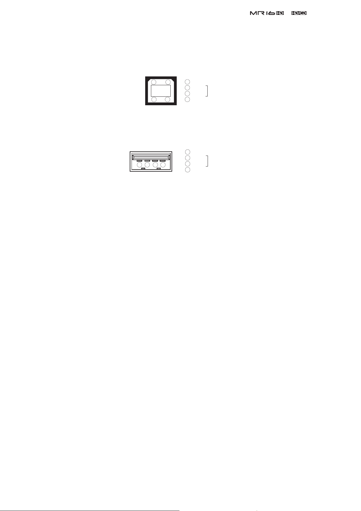
USB
Device USB 1.1. USB logo certifi cate not acquired. Connecting a USB key
board and a storage device for fi le transfer is possible.
Connector A type
1
2 1
3 4
2
3
4
VBUS
D D +
GND
DATA
USB
Device USB 2.0 high speed. USB logo certifi cate not acquired. File transfer be
tween PC and MR16 is possible.
Format B type
1
VBUS
2
D -
1 2 3 4
3
4
D +
GND
DATA
< MAJOR SPECS. >
Record & Playback
Medium Internal 3.5” HD
Sampling Frequency 44.1 kHz
Resolution 16 bits linear
File System FAT-32
Number of Track 16
A/D & D/A Converter
A/D 24 bits delta-sigma, Cirrus Logic CS5331
D/A 24 bits delta-sigma, Cirrus Logic CS4345
Fader 256 steps, 30 mm
CD-R/RW Drive Accession No. 0221205
< CHARACTERISTICS >
Maximum Output Level
ST OUT + 2 dBV ± 1 dB (full scale level)
AUX OUT + 2 dBV ± 1 dB (full scale level)
PHONES 50 mW or more (32 Ω load, 1 kHz)
Reference Output Level
ST OUT - 10 dBV ± 4 dB (Fader fi xed at standard position (0 dB), 1 kHz)
AUX OUT - 10 dBV ± 4 dB (Fader fi xed at standard position (0 dB), 1 kHz)
Frequency Response
ST OUT 20 Hz ~ 20 kHz + 2 dB, - 3 dB (MIC/LINE)
AUX OUT 20 Hz ~ 20 kHz + 2 dB, - 3 dB (MIC/LINE)
PHONES 50 Hz ~ 15 kHz + 2 dB, - 3 dB (50 mW, 32 Ω load)
T.H.D.
MIC -> ST OUT 0.1 % or less (Full scale level - 2 dB, 1 kHz)
LINE -> ST OUT 0.1 % or less (Full scale level - 2 dB, 1 kHz)
LINE -> PHONES 0.1 % or less (50 mW, 32 Ω load, 1 kHz)
Dynamic Range 89 dB or more
S/N
LINE 89 dB or more (IHF A, input terminated by 150 Ω resistor.)
MIC 80 dB or more (IHF A, input terminated by 150 Ω resistor.)
5

&
Residual Noise
LINE - 87 dBV or less (DIN, input terminated by 150 Ω resistor.)
MIC - 78 dBV or less (DIN, input terminated by 150 Ω resistor.)
PHONES - 85 dBV or less (DIN)
Crosstalk 65 dB or more (1 kHz)
LINE (TRIM : MIN) 85 dB or more (1 kHz, full scale level is input to adjacent channel.)
MIC (TRIM : MAX) 75 dB or more (1 kHz, full scale level is input to adjacent channel.)
Click Noise
Power On/Off - 20 dBVp-p or less (ST OUT)
Others - 30 dBVp-p or less (ST OUT)
Phantom
Voltage + 48 ± 2 V, On/Off on all channels at once by MENU setting.
Service Manual
< OTHERS >
Dimensions 400 (W) x 85 (H) x 265 (D) mm (including protruding portion)
Weight
Power
JPN 100 V AC
USA 120 V AC
EUR/UK
Power Consumption
Usage Condition
Environmental Condition
Standard Temperature
Standard humidity 65 ± 5 %
Characteristics Guaranteed
Temperature + 5 °C ~ + 40 °C
Humidity 30 % ~ 70 %
Voltage deviation ± 5 % or less
Operation Guaranteed
Temperature + 5 °C ~ + 45 °C
Humidity 85 % or less
Voltage deviation ± 10 % or less
3.3 kg
230 V AC
14 W
Horizontal, continuous operation
20 ± 2 °C
< STANDARDS >
Vibration & Drop Tests Comply to Fostex Company technical standards
Safety Standard
Others
EMI EN55011 Group 1 Class B
EN61000-3-2 & 3-3
EMS EN61000-6-1 (Year 2001 version)
Environment Response RoHS
IEC60065
directive
compliance
Specifi cations and physical appearance are subject to change without notice for product improvement.
6
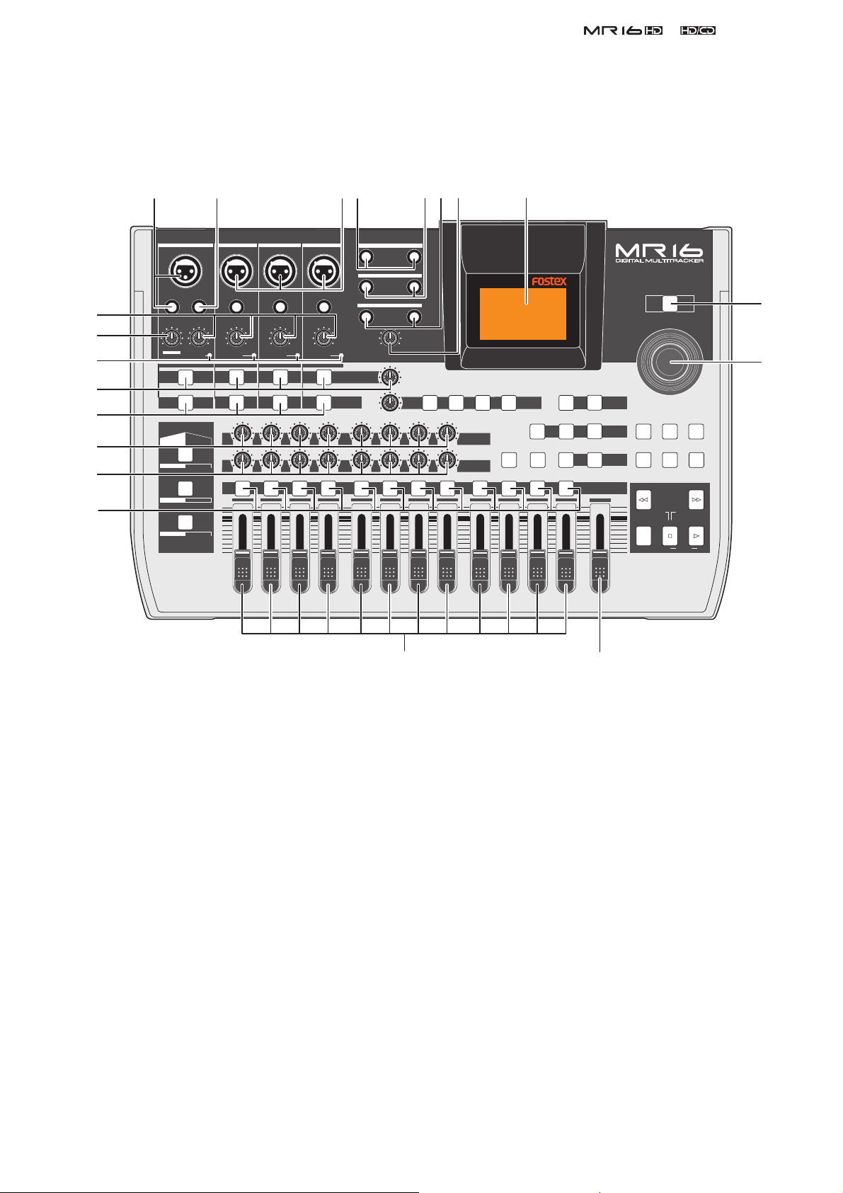
2. CONTROLS, INDICATORS & CONNECTORS
< Top Panel Section 1 >
1 2 34 567 8
&
Service Manual
20
19
18
17
16
15
14
13
INPUT A INPUT B INPUT C INPUT D
UNBAL
INSERT/GUITAR
UNBAL
TRIM
TRIM
PEAK
AMP
US METAL
PEAK
LINE
MAX
MIN
DISTORTION
MIN
LINE MIC
MAX
GUITAR
INPUT A INPUT B INPUT C INPUT D
MIC
SIMULATION
SIMULATION
DYNAMIC BRIT STACK
CONDENSER
TUBE
60'S COMBO
MIC
100
R
L
ABC1 DEF2
1
UNBAL
TRIM
PEAK
LINE
010
LR
2
BALBALBALBAL
UNBAL
TRIM
PEAK
MIC
MIC
LINE
TO STEREO BUSS LEVEL
INPUT EQ
010
LR
GHI3 JKL4
3
010
100
LR
RL
4 8
L
1
1
MNO5 YZ9PQR6 +-_0STU7 VWX8 DELETE
5
STEREO OUT
AUX OUT
PHONES
VOLUME
MIN
MAX
MIN
MIN MAX
REVERB / DELAY TIME
100
RL
6
R
2
2
MAX
EFFECT
POWERFUL
BOUNCE MODE
NATURAL
DELAYPLATEHALLROOM
EFFECT SEND
010
100
PAN
LR
RL
7
9/10 11/12 13/14 15/16
15/16 > STEREO WAV FILE
BOUNCE
BRIGHT
MASTERING
B / OUTA / INPLAY MODEAUTO PUNCH
LOCATE
REC SELECT
MASTER
MAX
MIN
POWER
MENU / ENTER
STORE
TIMEBASE SELECT
RHYTHM GUIDE DIRECT LOCATE
REWIND F FWD
LOCATE ABS ZERO
RECORD STOP PLAY
UNDO/REDO
CONTRAST
LOCATE REC END
A-B PLAY
9
10
1. [INPUT A] input connectors
2. [INSERT] connector
3. [INPUT B, C, D] input connectors
4. [STEREO OUT] jacks
5. [AUX OUT] jacks
6. [PHONES] jacks
7. [PHONES VOL] control
8. LCD display
9. [POWER] switch
10. [MENU/ENTER] rotary / push knob
11. [MASTER] fader
12. Track faders
13. [REC SELECT] keys
14. [PAN] controls
1112
15. [EFFECT SEND] controls
16. [INPUT EQ] keys
17. [TO STEREO BUSS] keys
[TO STEREO BUSS LEVEL] control
18. [PEAK] indicators
19. [DISTORTION] control
20. [TRIM] controls
7

&
Service Manual
< Top Panel Section 2 >
21 22
INPUT A INPUT B INPUT C INPUT D
UNBAL
INSERT/GUITAR
UNBAL
TRIM
PEAK
DISTORTION
MIN
LINE MIC
AMP
SIMULATION
US METAL
60'S COMBO
LINE
MAX
MIN
MAX
GUITAR
INPUT A INPUT B INPUT C INPUT D
MIC
SIMULATION
DYNAMIC BRIT STACK
CONDENSER
TUBE
TRIM
PEAK
MIC
100
R
L
ABC1 DEF2
1
UNBAL
TRIM
PEAK
LINE
010
LR
2
BALBALBALBAL
UNBAL
TRIM
PEAK
MIC
MIC
LINE
TO STEREO BUSS LEVEL
INPUT EQ
010
LR
GHI3 JKL4
3
010
100
LR
RL
4 8
L
1
1
MNO5 YZ9PQR6 +-_0STU7 VWX8 DELETE
5
STEREO OUT
AUX OUT
PHONES
VOLUME
MIN
MAX
MIN
MIN MAX
REVERB / DELAY TIME
100
RL
6
R
2
2
MAX
EFFECT
POWERFUL
BOUNCE MODE
NATURAL
DELAYPLATEHALLROOM
EFFECT SEND
010
100
PAN
LR
RL
7
9/10 11/12 13/14 15/16
15/16 > STEREO WAV FILE
BOUNCE
BRIGHT
MASTERING
B / OUTA / INPLAY MODEAUTO PUNCH
LOCATE
REC SELECT
MASTER
MAX
MIN
POWER
MENU / ENTER
STORE
TIMEBASE SELECT
RHYTHM GUIDE DIRECT LOCATE
REWIND F FWD
LOCATE ABS ZERO
RECORD STOP PLAY
UNDO/REDO
CONTRAST
LOCATE REC END
A-B PLAY
23
24
25
26
27
28
29
30
31
32
21. [REVERB/DELAY TIME] control
22. [EFFECT] keys
23. [BOUNCE MODE] key
24. [15/16 > STEREO WAV FILE] key
25. [MASTERING] keys
[POWERFUL] key
[NATURAL] key
[BRIGHT] key
26. [STORE] key
27. [UNDO/REDO] key
28. [TIME BASE SEL] key
29. [DIRECT LOCATE] key
30. [CONTRAST] key
3334353637
31. [RHYTHM GUIDE] key
32. Transport keys
[PLAY] key
[STOP] key
[RECORD] key
[F FWD] key
[REWIND] key
33. [LOCATE B/OUT] key
34. [LOCATE A/IN] key
35. [PLAY MODE] key
36. [AUTO PUNCH] key
37. Insert effect selection keys
8
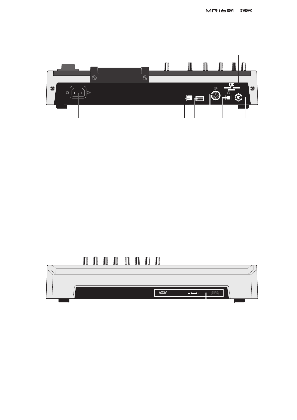
< Rear Panel Section >
INPUT A SEL
GTR CLEAN MIC/LINE
GTR DIST
&
Service Manual
1
1. [INPUT A SELECT] switch
2. [FOOT SW] jack
3. [DIGITAL OUT] connector
4. [MIDI OUT] jack
5. [USB HOST] connector
6. [USB] port
7. [AC IN] conector
< Side Panel Section >
USB HOST
USB
MIDI OUT
DIGITAL OUT
34567
FOOT SW
2
1. Internal CD-R/RW drive
COMPACT
R O M
ReWritable
Ultra Speed
1
9
&
Service Manual
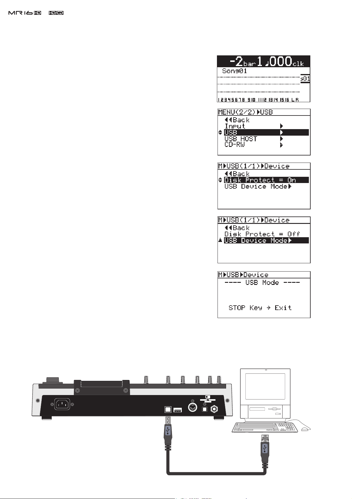
3. SOFTWARE UPDATE
1) Connect the AC power cable to the AC IN connector.
2) Press the MR16 power switch.
3) Press the [MENU/ENTER] dial to enter the MENU mode.
4) Rotate the [MENU/ENTER] dial and select the “USB” menu.
5) Press the [MENU/ENTER] dial.
6) Rotate the [MENU/ENTER] dial and select the “Disk Protect”
menu.
7) Press the [MENU/ENTER] dial and set “Disk Protect” to “Off” by
rotating the [MENU/ENTER] dial. Then, press the [MENU/EN-
TER] dial. With this setting, the Disk Protect mode is turned off
indicating the condition that the software update fi le can be copied
to the MR16 internal HDD.
8) Rotate the [MENU/ENTER] dial to select the “< < Back” menu and
press the [MENU/ENTER] dial.
9) Rotate the [MENU/ENTER] dial and select the “USB Device
Mode” menu.
10) Press the [MENU/ENTER] dial. If MR16 is correctly put into the
USB mode, the display on the right will appear on the LCD. Now
MR16 is ready to connect to PC or Macintosh.
11) Connect the USB cable from the MR16 USB port to PC on which
Windows XP/2000 is running or Macintosh on which OS X is run-
ning.
CAUTION:
MR16can be connected to PC on which Windows XP/2000 is running or Macintosh on which
OS X is running for software update as well as audio data transfer. Of course PC/Macintosh
has to be equipped with a USB port.
10
INPUT A SEL
MIC/LINE
GTR CLEAN
GTR DIST
USB USB HOST MIDI OUT DIGITAL OUT FOOT SW
USB port
USB port
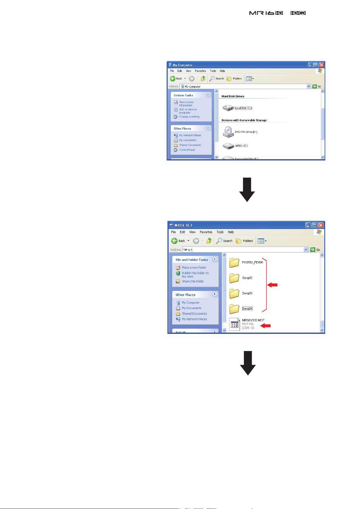
12) PC or Macintosh recognizes MR16 as an external removable disk.
(a) Windows XP/2000
The example on the right indicates that
MR16 is recognized as a removable disk
(E) in the My Computer on Windows XP
PC. Unzip the software update fi le with
“zip” extension (e.g. MR16_V102.zip)
normally sent together with a technical
bulletin. If you do so, a software update
fi le (e.g. MR16V102.MOT) will be cre-
ated. Place a newly created software up-
date fi le with “MOT” (motorola format)
extension in the root directory tree of the
Removable disk (E).
&
Service Manual
By double-clicking the removable drive
(E) (MR16), the window on the right will
appear. You can see that the software up-
date fi le (MR16V102.MOT) is placed in
the top directory tree of the Removable
Disk (E).
MR16
song folder
MR16 software
update file
Continue to the next page.
11
&
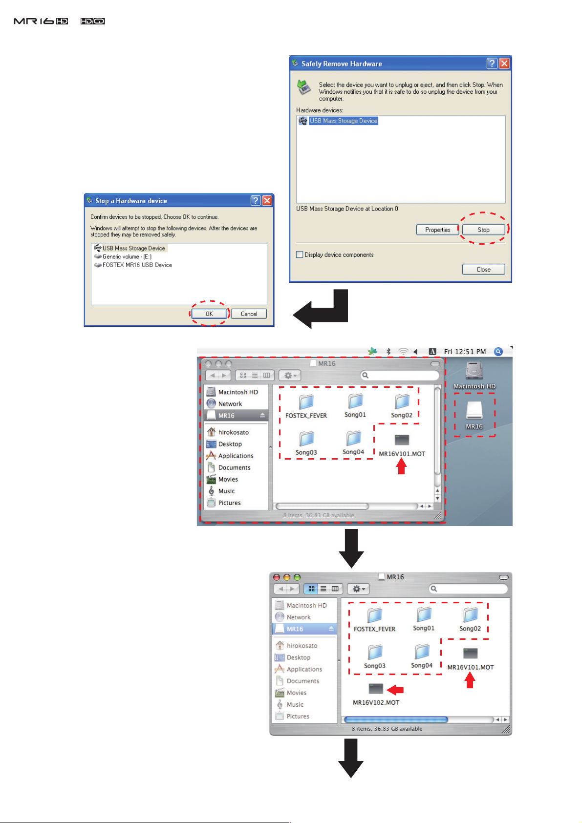
After transferring the software update fi le is com-
Service Manual
pleted,
pressing the MR16 STOP key. First, you need
to safely remove the MR16 from PC side by
opening the “Safety Removable Hardware” in
the tool bar and pressing the “Stop” button on
Windows XP/2000 PC.
USB connection from the MR16 side.
do not tun off the USB connection by
Then, you can turn off the
Press this OK butten befor turning off the
MR16 USB mode by pressing theOK key.
Press this STOP butten befor turning off
the MR16 USB mode by pressing
the STOP key.
(b) Macintosh OS X
MR16 is recognized as
“MR16” on the Macintosh
OS X desktop. By double-
clicking the MR16 icon, the
window on the right will
appear. There are fi ve song
folders and one software
update file “MR16V101.
MOT”.
Unzip the software update file with “zip”
extension (e.g. MR16_V102.zip) normally
sent together with a technical bulletin.
MR16 Song folder
MR16 Software
update file
12
Copy and paste a newly created software fi le
with “MOT” (motorola format) extension
(e.g. MR16V102.MOT) onto a root direc-
tory of MR16 HDD connected to Macintosh
(OS X).
MR16
Song folder
MR16
Softwareupdate file
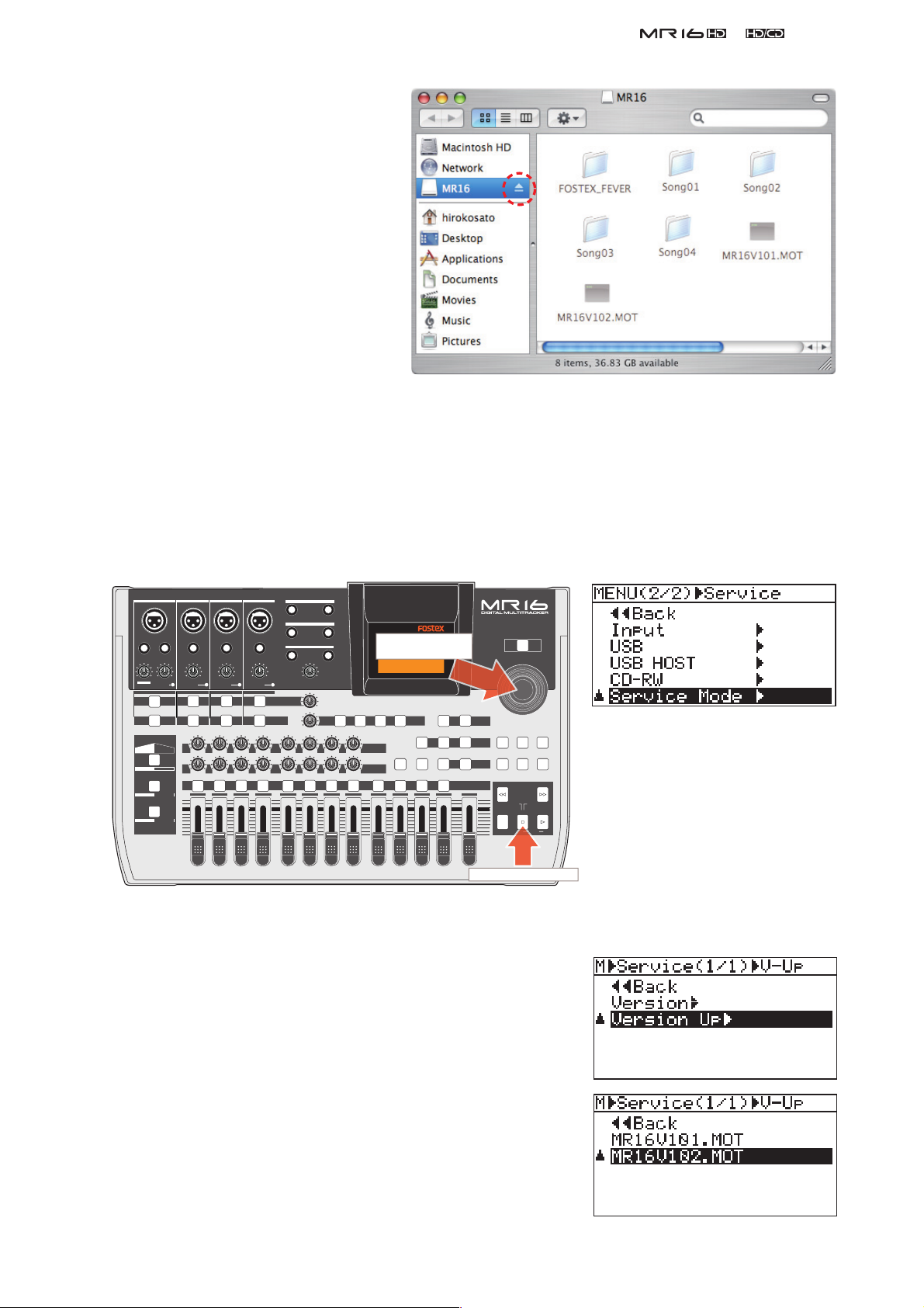
After transferring the software update
H
P
[MENU/ENTER] key.
file is completed,
do not tun off the
USB connection by pressing the
MR16 STOP key. First, as shown
on the right, you need to press the
EJECT button on Macintosh.
Then,
you can turn off the USB connection
from the MR16 side.
&
Press the EJECT button
before turning off the
MR16 USB mode by
pressing the STOP key.
Service Manual
CAUTION:
There is a case that it takes time for PC or Macintosh to recognize MR16 as an external device.
While the “ACC” (access) indication on the upper right of the MR16 LCD is fl ashing in the USB
mode, do not disconnect the USB cable between MR16 and PC / Macintosh.
13) Disconnect the USB cable between MR16 and PC / Macintosh.
14) On MR16 with the normal display appears, press the [MENU/ENTER] dial while holding down the [STOP]
key to access the Service Mode menu.
INPUT A INPUT B INPUT C INPUT D
UNBAL
INSERT/GUITAR
UNBAL
UNBAL
TRIM
PEAK
DISTORTION
LINE MIC
MIN
MAX
GUITAR
INPUT A INPUT B INPUT C INPUT D
AMP
MIC
SIMULATION
SIMULATION
DYNAMIC BRIT STACK
CONDENSER
US METAL
TUBE
60'S COMBO
TRIM
PEAK
LINE
MAX
MIN
MIC
100
R
L
ABC1 DEF2
1
LINE
010
LR
2
TRIM
PEAK
MIC
010
LR
GHI3 JKL4
3
L
R
STEREO OUT
BALBALBALBAL
1
2
UNBAL
TRIM
PEAK
LINE
AUX OUT
1
2
PHONES
VOLUME
MIN
MIC
TO STEREO BUSS LEVEL
100
RL
4 8
MAX
MAX
MIN
INPUT EQ
MIN MAX
REVERB / DELAY TIME
010
100
LR
RL
MNO5 YZ9PQR6 +-_0STU7 VWX8 DELETE
5
6
EFFECT SEND
010
100
LR
RL
7
ress the
DELAYPLATEHALLROOM
EFFECT
POWERFUL
PAN
9/10 11/12 13/14 15/16
BOUNCE MODE
NATURAL
15/16 > STEREO WAV FILE
BOUNCE
BRIGHT
MASTERING
B / OUTA / INPLAY MODEAUTO PUNCH
LOCATE
REC SELECT
MASTER
MENU / ENTER
TIMEBASE SELECT
RHYTHM GUIDE DIRECT LOCATE
REWIND F FWD
MAX
LOCATE ABS ZERO
RECORD STOP PLAY
MIN
CONTRAST
POWER
STORE
UNDO/REDO
NOTE:
Pressing the [MENU/ENTER]
dial while holding down the
[STOP] key allows to access
LOCATE REC END
A-B PLAY
the "Version" and "Version
Up" Service menu only. To
fully access all the Service
old down [STOP] key.
menus, as mentioned on page
16, press the [MENU/ENTER]
dial while holding down the
[STOP] and [POWER] keys.
15) Rotate the [MENU/ENTER] dial and select the “Service Mode”
menu.
16) Press the [MENU/ENTER] dial.
17) Rotate the [MENU/ENTER] dial and select the “Version Up” menu.
18) Press the [MENU/ENTER] dial.
19) Rotate the [MENU/ENTER] dial and select a software update fi le
with the version number you would like to update.
NOTE:
As long as the fi le name is different, up to fi ve software
update fi les can be placed in the root directory.
20) Press the [MENU/ENTER] dial.
13
&
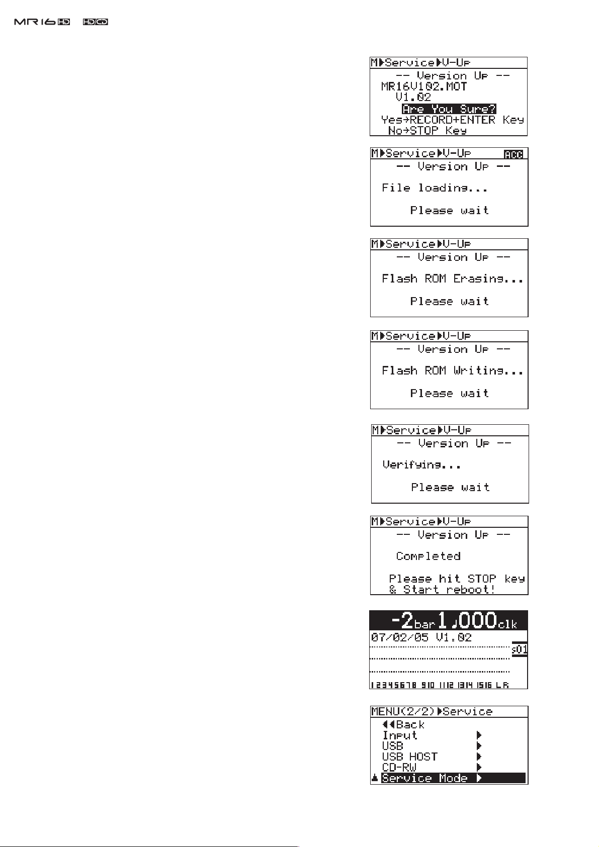
21) The selected software fi le is displayed together with the software
22) The software updating procedures begin. “File loading...”, “Flash
Service Manual
version number. To go on, press the [MENU/ENTER] dial while
holding down the [REC] key.
ROM Erasing...” and “Flash ROM Writing...” will appear in order.
It will take about one minute to complete the procedures.
23) Upon completion, “Completed” will appear on the LCD.
24) Turn off the power once and then back on to complete the software
update procedures. In the meantime, confi rm the software version
number and the programming date displayed for a short instance in
the boot-up process.
The software version can be checked by the “Version” Service
Mode menu. In the condition with normal display appears, press the
[MENU/ENTER] dial while holding down the [STOP] key to access
the Service Mode menu. If you do so, the display on the right will
appear on the LCD. Rotate the [MENU/ENTER] dial to select the
“Service Mode” menu and press the [MENU/ENTER] dial.
14
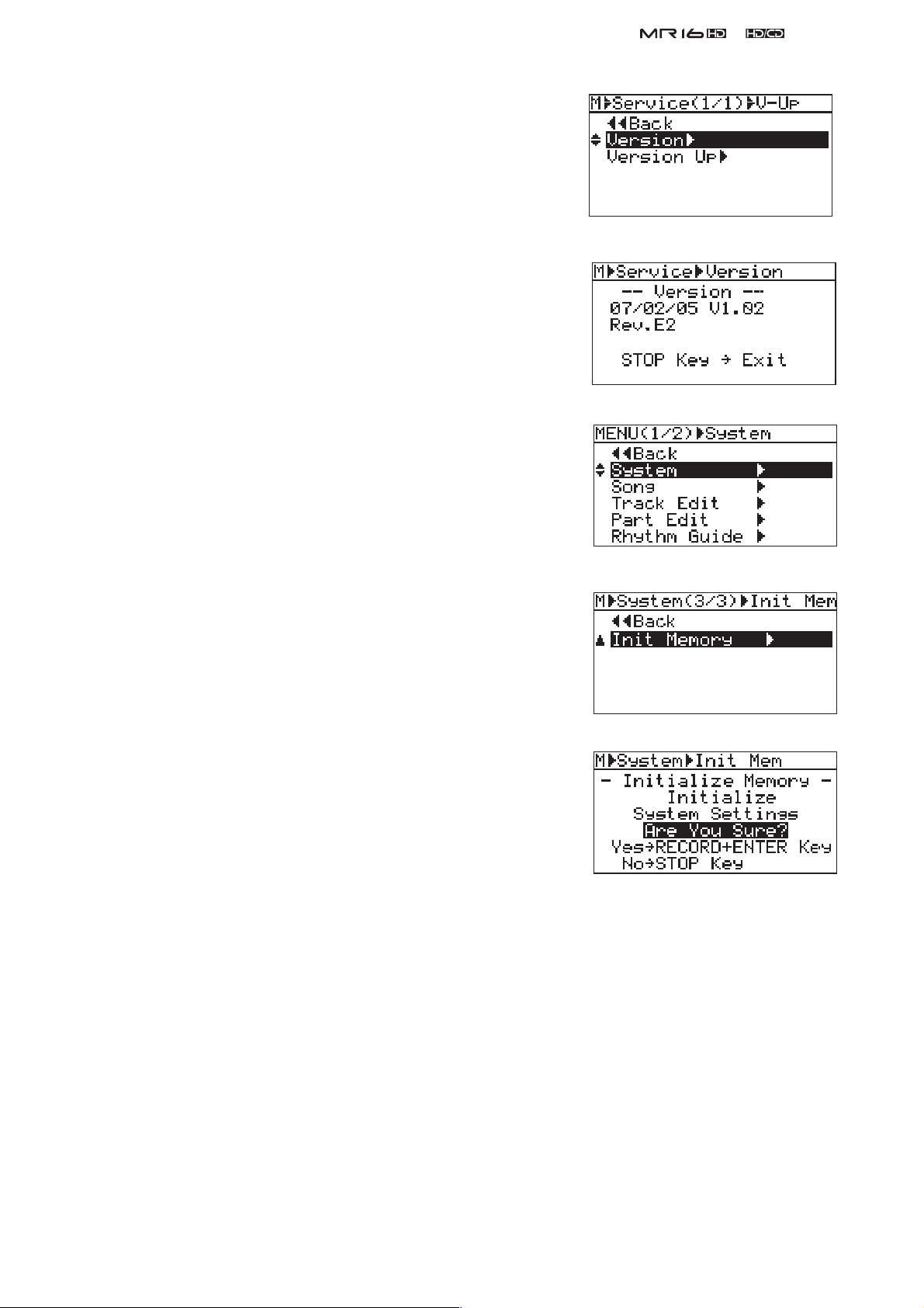
Select the “Version” menu and press the [MENU/ENTER] dial.
The display on the right will appear on the LCD. It indicates that
the programming date is
V1.02 and the CPU revision number is E2. To get back to the normal
display, press the [STOP] key.
25) Press the [STOP] key to return to the normal display mode. Then,
press the [MENU/ENTER] dial to enter the MENU mode.
26) Rotate the [MENU/ENTER] dial to select the "System" menu and
press the [MENU/ENTER] dial.
February 5th, 2007,
the version number is
&
Service Manual
27) Rotate the [MENU/ENTER] dial and select the “Init Memory”
menu.
28) Press the [MENU/ENTER] dial.
29) The display contents on the right appear on the LCD. Press the
[MENU/ENTER] dial while holding down the [RECORD] key. This
operation will initialize all the system settings to default.
CAUTION:
The “Initialize Memory” operation sets all the system
settings to the default values. For example, the “Disk Protect” setting in the USB menu is set to
“ON” after initializing the memory. If you would like to update the software in future, please re-
member that it has to be set to “OFF” again.
15
&
Service Manual
4. SERVICE MENU
In addition to various MENU modes, SERVICE menus are available to check and maintain the MR16 condition.
Please utilize them when servicing MR16.
4-1. Entering Service Menu
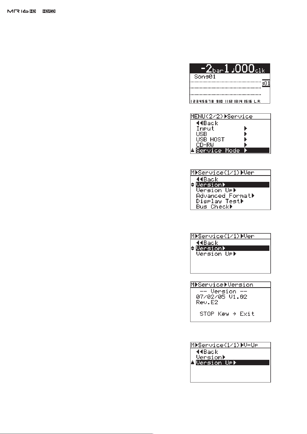
1) Connect the AC cable and power on MR16. After the bootup proce-
dure is completed, the display on the right will appear on the MR16
LCD.
2) Press the [MENU/ENTER] dial while holding down the [STOP]
and [POWER] keys. If you do so, "Service Mode" is displayed on
the MR16 LCD.
CAUTION:
3) Rotate the [MENU/ENTER] dial and select “Service Mode”. Then,
press the [MENU/ENTER] dial. You can see that the following ser-
vice menus will appear on the MR16 LCD.
Select one of the service menus you would like to execute and press
the [MENU/ENTER] dial.
If the [POWER] key is held down for more than three
seconds, MR16 turns off. Please be careful to expedite
the above manipulation 2).
4-2. Version
In the “Version” service menu, the current MR16 software version as well
as the corresponding software programming date can be checked.
1) After selecting the “Version” menu, press the [MENU/ENTER] dial
to check the current software version and the programming date.
The example on the right indicates that the software version is
“V1.02” the programming date is February 5th, 2007 and the CPU
revision number is E2.
16
By pressing the STOP key, MR16 returns to the service menu select
condition.
4-3. Version Up
The “Version Up” service menu allows you to update the MR16 software
by placing the software update fi le in the root directory tree of the MR16
3.5” internal hard disk. For the update procedures, refer to the previous
section “3. SOFTWARE UPDATE” on page 10 in detail.
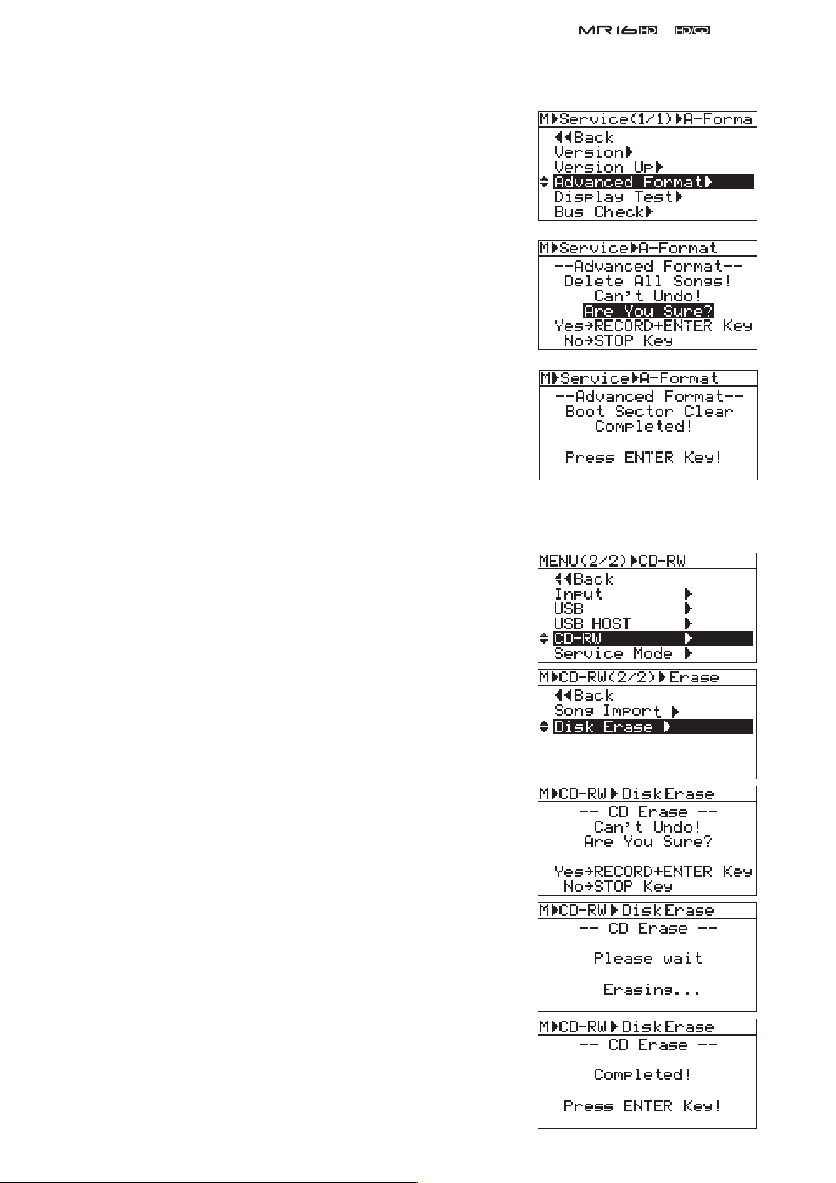
4-4. Advanced Format
MR16 checks the remaining capacity / partition information written on the
internal HD in the bootup process after powering on. In case this informa-
tion does not match the current HD condition, the “Advanced Format”
service menu can be used. For example, even if no song has been created
(recorded) but the remaining capacity indicates only 10MB, execute the
“Advanced Format” menu.
As indicated on the right, please remember that executing the “Advanced
Format” deletes all the songs recorded on the internal HD.
Upon completion of “Advanced Format”, the message “Boot Sector Clear”
appears on the LCD.
&
Service Manual
NOTE:
In case MR16 is not booted up correctly and displays an alert
message such as “Please Wait!” permanently, power if off once.
Then, while holding down the [STOP] key, power on MR16.
This mode allows to boot up without loading any recorded songs.
Next, execute the “Advanced Format” menu.
4-5. CD-RW Disk Erase
Executing the “Disk Erase” service menu erases all existing song data on
the CD-RW disk put into the MR16HD/CD internal CD-R/RW drive.
1) Rotate the [MENU/ENTER] dial and select “CD-RW”. Then, press
the [MENU/ENTER] dial.
2) Rotate the [MENU/ENTER] dial and select “Disk Erase”. Then,
press the [MENU/ENTER] dial.
To go on, press the [MENU/ENTER] dial while holding down the
3)
[REC] key.
The CD-RW disk erasing procedures begin. “Erasing...” will appear .
4)
It will take about one minute to complete the procedures.
Upon completion, “Completed!” will appear on the LCD.
5)
17
&
Service Manual
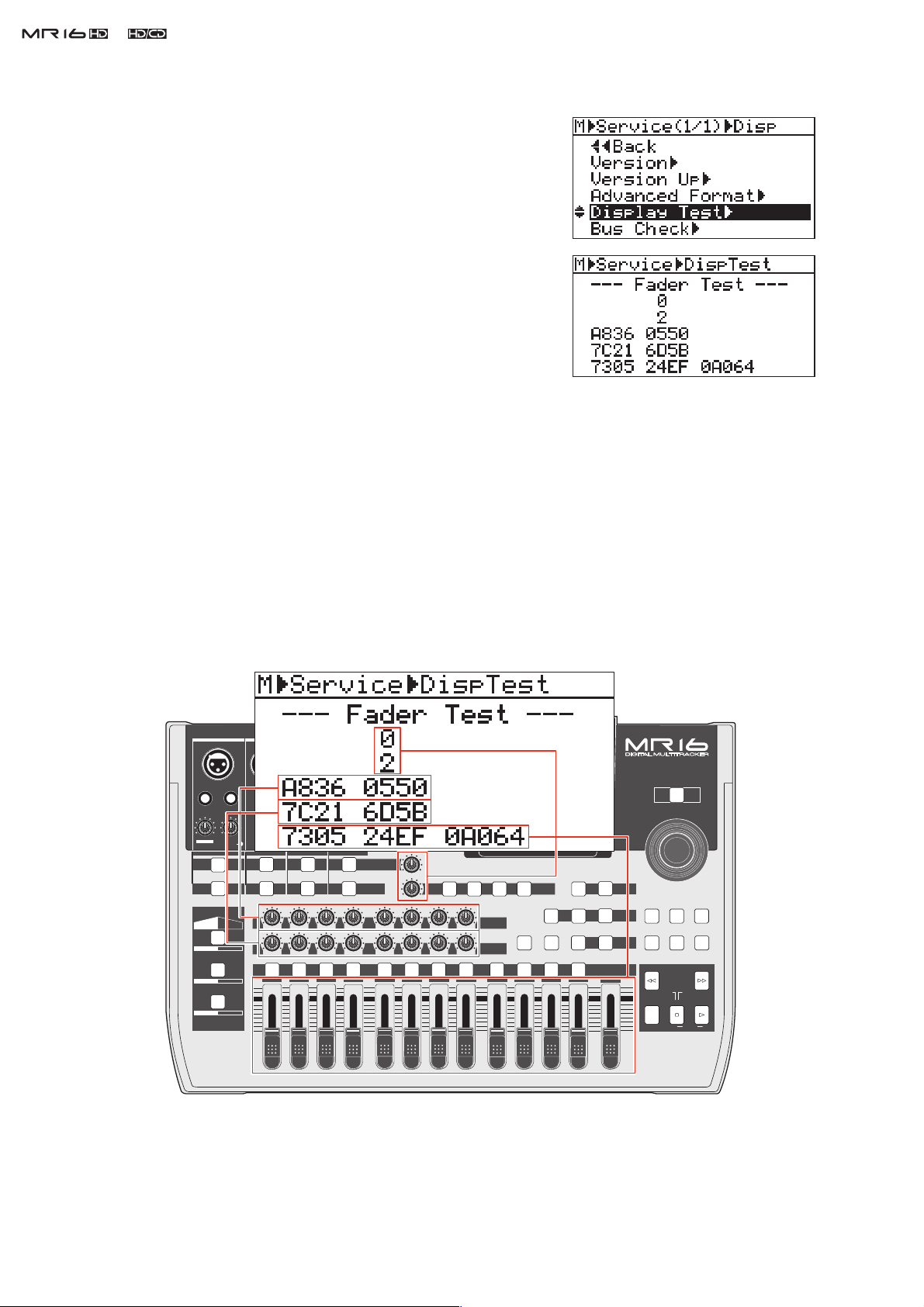
4-6. Display Test
This menu checks if the EFFECT SEND / PAN / REVERB/DELAY pots &
faders / self-illuminating tact switches are working properly.
1) After selecting the “Display Test” menu, press the [MENU/ENTER]
dial.
2) Press the [MENU/ENTER] dial again. If you do so, the display on
the right will appear on the MR16 LCD.
As shown in the drawing below, each value the EFFECT SEND /
PAN / TO STEREO BUSS LEVEL / REVERB/DELAY pots & fad-
ers position. Rotate the EFFECT SEND / PAN pots and move the
faders to check if the value changes from "0" to "F" in hexadecimal
depending on the pots / fades position as follow.
EFFECT SEND Pots 1 ~ 8: 0 (CCW) ~ F (CW)
PAN pots 1 ~ 8: 0 (CCW) ~ F (CW)
TO STEREO BUSS LEVEL pot: 0 (CCW) ~ F (CW)
REVERB/DELAY pot: 0 (CCW) ~ F (CW)
Channel faders (1 ~ 8, 9/10, 11/12, 13/14, 15/16): 0 (down) ~ F (up)
Master fader: 0 (down) ~ F (up)
INPUT A INPUT B INPUT C INPUT D
UNBAL
DISTORTION
MIN
MAX
GUITAR
INPUT A INPUT B INPUT C INPUT D
MIC
SIMULATION
DYNAMIC BRIT STACK
CONDENSER
TUBE
INSERT/GUITAR
TRIM
PEAK
LINE MIC
AMP
SIMULATION
US METAL
60'S COMBO
UNBAL
TRIM
PEAK
LINE
L
MAX
MIN
MIC
100
R
ABC1 DEF2
1
UNBAL
TRIM
PEAK
LINE
010
LR
2
BALBALBALBAL
UNBAL
TRIM
PEAK
MIC
MIC
LINE
TO STEREO BUSS LEVEL
INPUT EQ
010
100
LR
RL
GHI3 JKL4
3
4 8
L
R
STEREO OUT
1
2
AUX OUT
1
2
PHONES
VOLUME
MIN
MAX
MAX
MIN
MIN MAX
REVERB / DELAY TIME
010
LR
MNO5 YZ9PQR6 +-_0STU7 VWX8 DELETE
5
6
010
100
100
LR
RL
RL
7
DELAYPLATEHALLROOM
EFFECT
EFFECT SEND
PAN
9/10 11/12 13/14 15/16
POWERFUL
BOUNCE MODE
NATURAL
15/16 > STEREO WAV FILE
BOUNCE
BRIGHT
MASTERING
B / OUTA / INPLAY MODEAUTO PUNCH
LOCATE
REC SELECT
MASTER
POWER
MENU / ENTER
STORE
TIMEBASE SELECT
RHYTHM GUIDE DIRECT LOCATE
CONTRAST
REWIND F FWD
MAX
LOCATE ABS ZERO
RECORD STOP PLAY
MIN
UNDO/REDO
LOCATE REC END
A-B PLAY
18
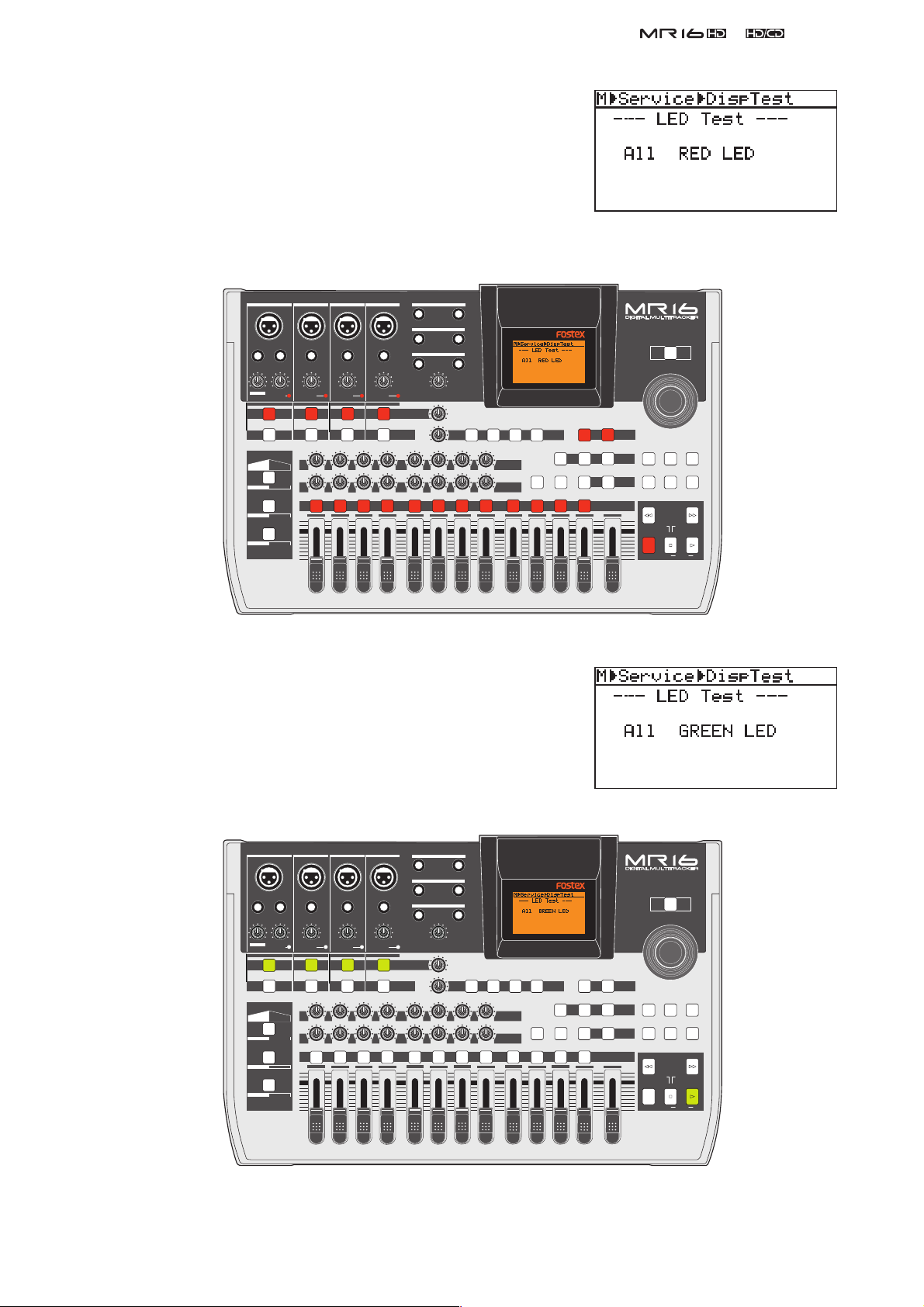
3) After checking, press the [MENU/ENTER] dial to proceed the next
Display Test. The next test is to check if the self-illuminating tact
switches are lit in red.
Check if the self-illuminating tact switches are properly lit in red as
indicated in the drawing below.
&
Service Manual
INPUT A INPUT B INPUT C INPUT D
UNBAL
INSERT/GUITAR
UNBAL
UNBAL
TRIM
PEAK
DISTORTION
LINE MIC
MIN
MAX
GUITAR
INPUT A INPUT B INPUT C INPUT D
AMP
MIC
SIMULATION
SIMULATION
DYNAMIC BRIT STACK
CONDENSER
US METAL
TUBE
60'S COMBO
LINE
MAX
MIN
TRIM
PEAK
MIC
L
ABC1 DEF2
1
TRIM
PEAK
LINE
010
100
LR
R
2
MIC
010
LR
GHI3 JKL4
3
L
R
STEREO OUT
BALBALBALBAL
1
2
AUX OUT
UNBAL
1
2
TRIM
PEAK
LINE
PHONES
VOLUME
MIN
MIC
TO STEREO BUSS LEVEL
INPUT EQ
100
RL
4 8
MAX
MAX
MIN
MIN MAX
REVERB / DELAY TIME
010
100
LR
RL
MNO5 YZ9PQR6 +-_0STU7 VWX8 DELETE
5
6
EFFECT SEND
010
100
LR
RL
7
DELAYPLATEHALLROOM
EFFECT
POWERFUL
PAN
9/10 11/12 13/14 15/16
4) After checking, press the [MENU/ENTER] dial to proceed the next
Display Test. The next test is to check if the self-illuminating tact
switches are lit in green.
BOUNCE MODE
NATURAL
15/16 > STEREO WAV FILE
BOUNCE
BRIGHT
MASTERING
B / OUTA / INPLAY MODEAUTO PUNCH
LOCATE
REC SELECT
MASTER
MENU / ENTER
TIMEBASE SELECT
RHYTHM GUIDE DIRECT LOCATE
REWIND F FWD
MAX
LOCATE ABS ZERO
RECORD STOP PLAY
MIN
POWER
STORE
CONTRAST
UNDO/REDO
LOCATE REC END
A-B PLAY
Check if the self-illuminating tact switches are properly lit in green
as indicated in the drawing below.
INPUT A INPUT B INPUT C INPUT D
UNBAL
DISTORTION
MIN
GUITAR
MIC
SIMULATION
DYNAMIC BRIT STACK
CONDENSER
TUBE
UNBAL
LINE
MAX
MIN
TRIM
PEAK
MIC
L
ABC1 DEF2
1
UNBAL
TRIM
PEAK
LINE
100
010
R
LR
2
INSERT/GUITAR
TRIM
PEAK
LINE MIC
MAX
INPUT A INPUT B INPUT C INPUT D
AMP
SIMULATION
US METAL
60'S COMBO
MIC
010
LR
GHI3 JKL4
3
L
R
STEREO OUT
BALBALBALBAL
1
2
AUX OUT
UNBAL
1
2
TRIM
PEAK
LINE
PHONES
VOLUME
MIN
MIC
TO STEREO BUSS LEVEL
INPUT EQ
100
RL
4 8
MAX
MAX
MIN
MIN MAX
REVERB / DELAY TIME
010
100
LR
RL
MNO5 YZ9PQR6 +-_0STU7 VWX8 DELETE
5
6
EFFECT SEND
010
100
LR
RL
7
DELAYPLATEHALLROOM
EFFECT
POWERFUL
PAN
9/10 11/12 13/14 15/16
BOUNCE MODE
NATURAL
15/16 > STEREO WAV FILE
BOUNCE
BRIGHT
MASTERING
B / OUTA / INPLAY MODEAUTO PUNCH
LOCATE
REC SELECT
MASTER
MENU / ENTER
TIMEBASE SELECT
RHYTHM GUIDE DIRECT LOCATE
REWIND F FWD
MAX
LOCATE ABS ZERO
RECORD STOP PLAY
MIN
POWER
STORE
CONTRAST
UNDO/REDO
LOCATE REC END
A-B PLAY
19
&
Service Manual
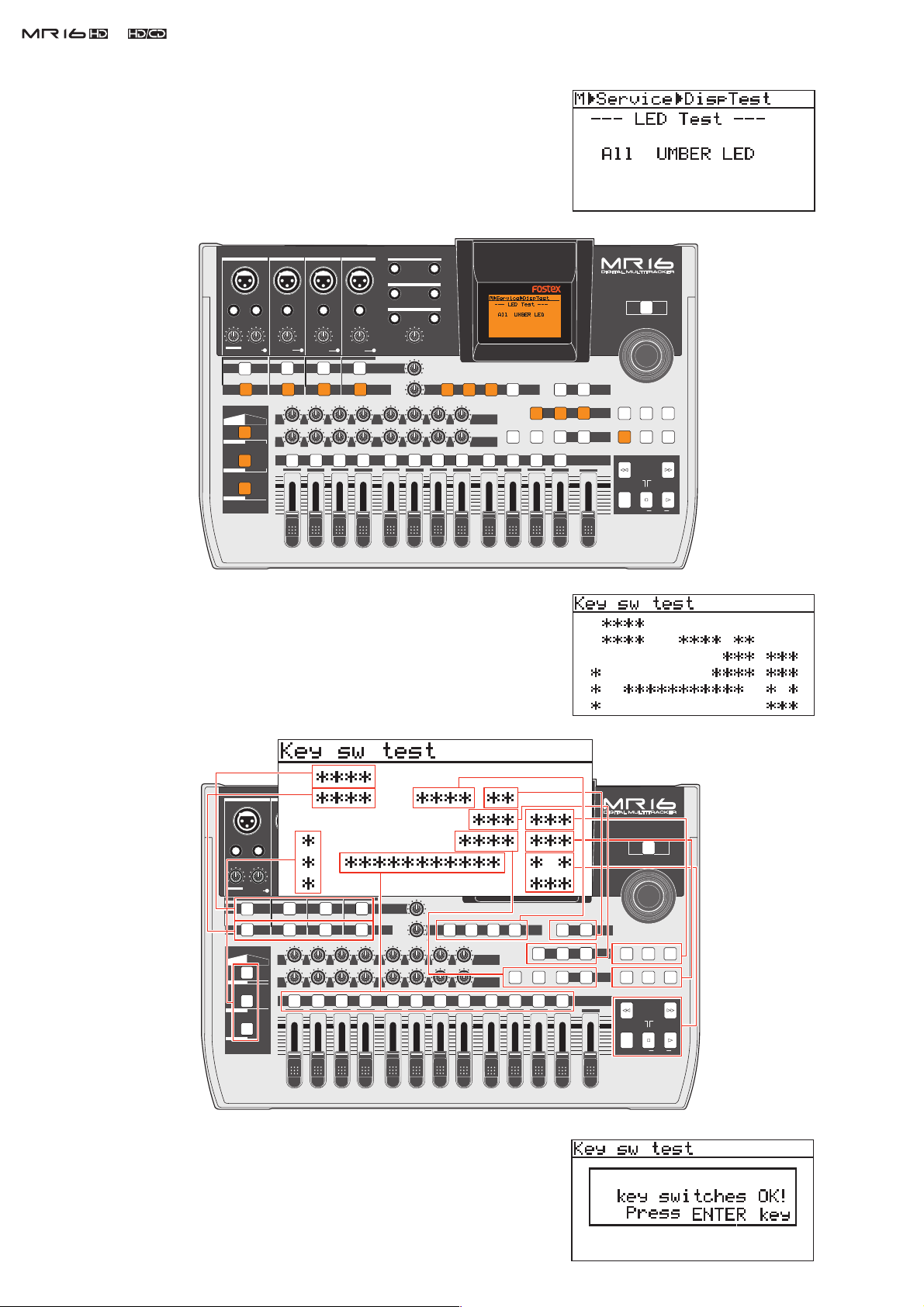
5) After checking, press the [MENU/ENTER] dial to proceed the next
Display Test. The next test is to check if the self-illuminating tact
switches are lit in umber.
Check if the self-illuminating tact switches are properly lit in orange
as indicated in the drawing below.
INPUT A INPUT B INPUT C INPUT D
UNBAL
DISTORTION
MIN
MAX
GUITAR
MIC
SIMULATION
DYNAMIC BRIT STACK
CONDENSER
TUBE
UNBAL
TRIM
PEAK
LINE
MAX
MIN
MIC
100
R
L
ABC1 DEF2
1
UNBAL
TRIM
PEAK
LINE
010
LR
2
INSERT/GUITAR
TRIM
PEAK
LINE MIC
INPUT A INPUT B INPUT C INPUT D
AMP
SIMULATION
US METAL
60'S COMBO
MIC
010
LR
GHI3 JKL4
3
L
R
BALBALBALBAL
UNBAL
TRIM
PEAK
LINE
STEREO OUT
1
2
AUX OUT
1
2
PHONES
VOLUME
MIN
MIC
TO STEREO BUSS LEVEL
INPUT EQ
100
RL
4 8
MAX
MAX
MIN
MIN MAX
REVERB / DELAY TIME
010
100
LR
RL
MNO5 YZ9PQR6 +-_0STU7 VWX8 DELETE
5
6
EFFECT SEND
010
100
LR
RL
7
DELAYPLATEHALLROOM
EFFECT
POWERFUL
PAN
9/10 11/12 13/14 15/16
BOUNCE MODE
NATURAL
15/16 > STEREO WAV FILE
BOUNCE
BRIGHT
MASTERING
B / OUTA / INPLAY MODEAUTO PUNCH
LOCATE
REC SELECT
MASTER
MENU / ENTER
TIMEBASE SELECT
RHYTHM GUIDE DIRECT LOCATE
REWIND F FWD
MAX
LOCATE ABS ZERO
RECORD STOP PLAY
MIN
POWER
CONTRAST
STORE
UNDO/REDO
LOCATE REC END
A-B PLAY
6) After checking, press the [MENU/ENTER] dial to proceed the next
Display Test. The next test is to check if the tact switches on the
MR16 top panel except the POWER SW is in good contact. If the tact
switch is pressed, the corresponding asterisk mark on the MR16 LCD
will go out. If not, the tact switch might be worn out and be replaced.
After all the tact switches are confi rmed to be in good contact, the
INPUT A INPUT B INPUT C INPUT D
UNBAL
DISTORTION
MIN
GUITAR
MIC
SIMULATION
DYNAMIC BRIT STACK
CONDENSER
TUBE
UNBAL
TRIM
PEAK
LINE
MAX
MIN
MIC
100
R
L
ABC1 DEF2
1
UNBAL
TRIM
PEAK
LINE
010
LR
2
INSERT/GUITAR
TRIM
PEAK
LINE MIC
MAX
INPUT A INPUT B INPUT C INPUT D
AMP
SIMULATION
US METAL
60'S COMBO
MIC
010
LR
GHI3 JKL4
3
L
R
STEREO OUT
BALBALBALBAL
1
2
AUX OUT
UNBAL
1
2
TRIM
PEAK
LINE
PHONES
VOLUME
MIN
MIC
TO STEREO BUSS LEVEL
INPUT EQ
100
RL
4 8
MAX
MAX
MIN
MIN MAX
REVERB / DELAY TIME
010
100
LR
RL
MNO5 YZ9PQR6 +-_0STU7 VWX8 DELETE
5
6
EFFECT SEND
010
100
LR
RL
7
DELAYPLATEHALLROOM
EFFECT
POWERFUL
PAN
9/10 11/12 13/14 15/16
BOUNCE MODE
POWER
15/16 > STEREO WAV FILE
BRIGHT
NATURAL
B / OUTA / INPLAY MODEAUTO PUNCH
REC SELECT
MASTER
BOUNCE
TIMEBASE SELECT
MASTERING
RHYTHM GUIDE DIRECT LOCATE
LOCATE
REWIND F FWD
MAX
LOCATE ABS ZERO
RECORD STOP PLAY
MIN
MENU / ENTER
STORE
CONTRAST
UNDO/REDO
LOCATE REC END
A-B PLAY
20
display on the right will appear on the MR16 LCD.
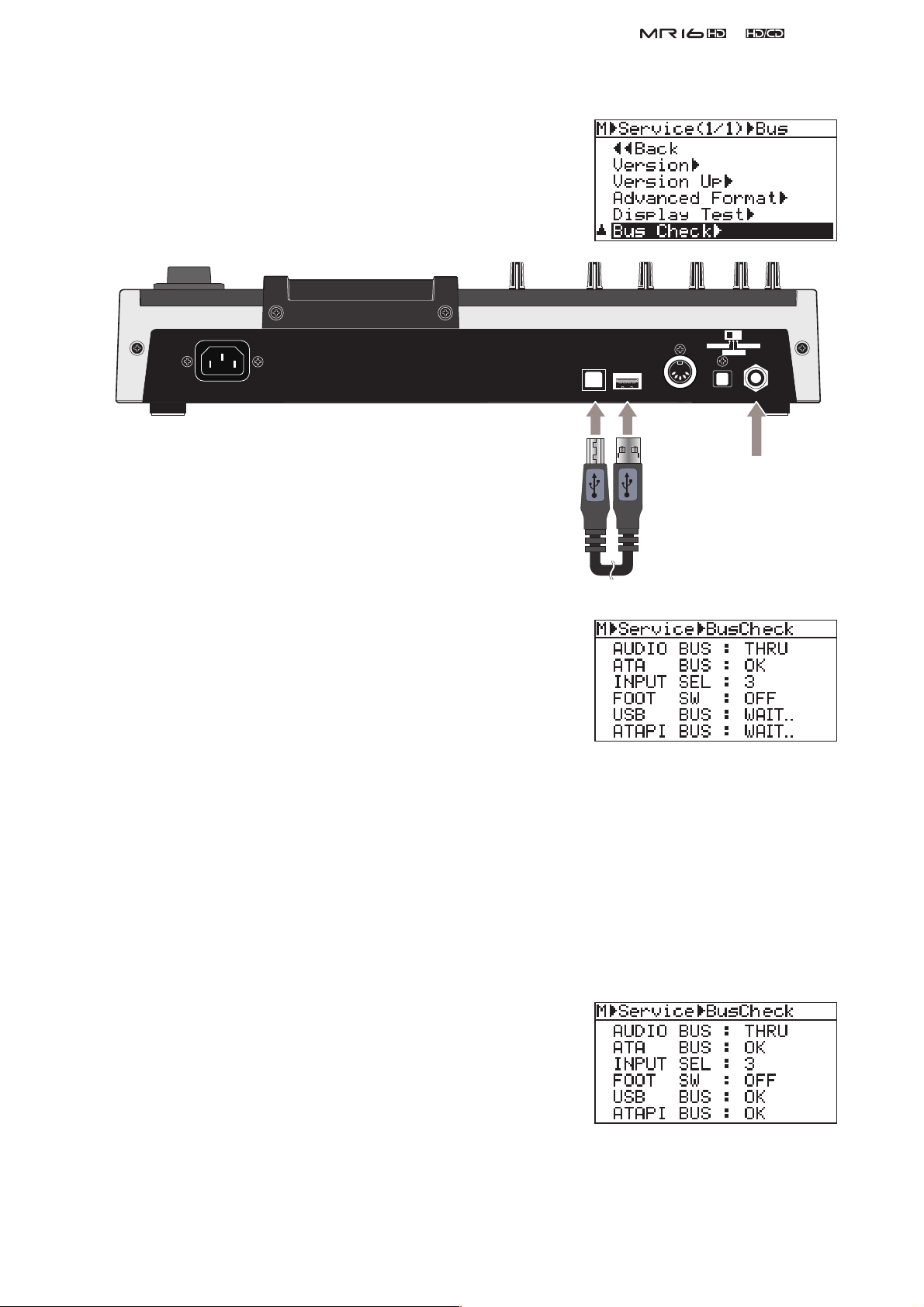
4-6. Bus Check
This menu checks if various bus signals connected to the CPU are cor-
rectly working or not.
1) After selecting the “Bus Check” menu, connect the foot SW to the
foot SW jack and the USB cable between the USB and USB HOST
ports.
2) Press the [MENU/ENTER] dial to initiate the Bus Check mode.
INPUT A SEL
GTR CLEAN MIC/LINE
GTR DIST
&
Service Manual
USB HOST
USB
MIDI OUT
DIGITAL OUT
FOOT SW
Foot SW
USB cable
(unlatched type)
• AUDIO BUS
The AUDIO BUS setting is fi xed at “THRU” in this menu. In the
“THRU” setting, the A/D and D/A converters are internally con-
nected. Also the CHAN A/C and B/D PAN setting are set to left
and right respectively. Thus, the signals fed to CHAN A and C are
summed and output from the STEREO OUT L and the signal fed to
CHAN B and D are summed and output from the STEREO OUT R.
This mode is convenient when checking the input circuit.
• ATA BUS
The “OK” sign indicates that the ATA bus communication between the internal HD and the CPU is properly
made. If the “NG” sign appears, something must be wrong with the ATA bus communication.
• INPUT SEL
The “INPUT SEL” indicates the number corresponding to the INPUT A SELECT switch setting as follow.
GTR CLEAR: 2
GTR DISTORTION: 1
MIC/LINE: 3
• FOOT SW
When an unlatched type foot switch is connected and it is pressed,
the “ON” indication will appear. If the foot switch is released or is
not connected, the “OFF” sign will appear.
• USB BUS
If the “USB BUS” section indicates the “OK” sign 3 ~ 5 seconds
after the “WAIT..” sign is displayed, the USB HOST function works
properly. If the “NG” sign is displayed, press the
[MENU/ENTER]
dial and then try to enter the Bus Check mode again by pressing the [MENU/ENTER] dial.
• ATAPI BUS
The “OK” sign indicates that the ATAPI bus communication between the CD-R/RW drive and the CPU is
properly made. If the “NG” sign appears, something must be wrong with the ATAPI bus communication.
21
 Loading...