

Page 1

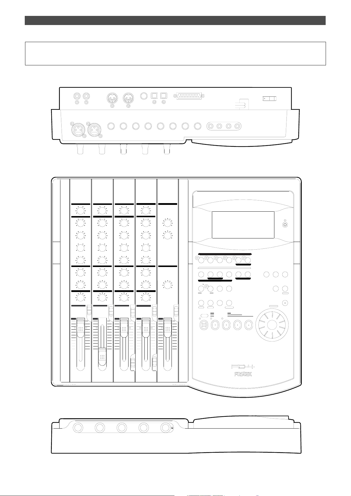
Owner’s Manual
Model
Digital Multitracker
AUX
AUX
AUX
0
00
AUX1
AUX1
AUX1
AUX1
AUX2
EQ
EQ
HIGH
HIGH
MID
GAIN
MID
SHIFT
300
200
LOW
-
PAN
L
1
10
5
0
0
0
-
+
MID
GAIN
0
0
-
+
MID
SHIFT
900
900
300
2k
200 5k
5k
LOW
0000
-
+
MON MON MON MON
0
000
TRK1INPUT
PAN
MON L MON RMON L MON R
PAN PAN PAN
L
R
INPUT SELINPUT SEL INPUT SEL
INPUT
OFF
TRK 1
2 3 4
10
5
0
AUX2
AUX2
EQ
HIGH
HIGH
0
-
+
+
+
2k
+
TRK2INPUT
R
INPUT
OFF
TRK 2
MID
GAIN
MID
SHIFT
300
LOW
PAN
200 5k
MON L MON R
10
5
0
0
-
+
900
2k
-
+
TRK3INPUT
L
R
INPUT
OFF
TRK 3
H
M
L
LEVEL LEVEL
MID
GAIN
MID
SHIFT
LOW
PAN
300
200 5k
MON L MON R
INPUT SEL
10
5
0
AUX
0
AUX2
EQ
0
-
+
0
+
-
900
2k
+
-
TRK4INPUT
PAN
L
R
INPUT
OFF
TRK 4
H
M
L
MASTER
SELECTOR
L/R
1
0
2
010
MON SECTION
010
10
5
0
AUX RTN
L/R+MON
10
RECORD TRACK
1/L
PREVIEW
START IN OUT
AUTO PUNCH
AUTO RTN
HOLD/ STORE
PGM SEL
AUTO RTN
VARI
AUTO PLAY
PITCH
SHIFT
L/R
MON
P. EDIT
CLIPBOARD PLAY
LOCATE ABS 0
AUTO
LOCATE REC END
PUNCH
RECORD
4/R3/L2/R
END IN OUT
CLIPBOARD
UNDO/
REDOEDIT
LOCATE
LOC MEM
DIGITAL MULTITRACKER
ADD. TRACK
RL
TIME BASE
SETUP
SELDISP SEL
EXIT
EXECUTE
/YES
/NO
ELECT
ACCESS
SHUTTLE
JOG
F FWDREWINDPLAYSTOP
Page 2
Safety Instructions
CAUTION
RISK OF ELECTRIC SHOCK
DO NOT OPEN
CAUTION: TO REDUCE THE RISK OF ELECTRIC SHOCK,
DO NOT REMOVE COVER (OR BACK).
NO USER - SERVICEABLE PARTS INSIDE.
REFER SERVICING TO QUALIFIED SERVICE PERSONNEL.
"WARNING"
"TO REDUCE THE RISK OF FIRE OR ELECTRIC SHOCK,
DO NOT EXPOSE THIS APPLIANCE TO RAIN OR
MOISTURE."
SAFETY INSTRUCTIONS
1. Read Instructions - All the safety and operating instructions
should be read before the appliance is operated.
2. Retain Instructions - The safety and operating instructions
should be retained for future reference.
3. Heed Warnings - All warnings on the appliance and in the
operating instructions should be adhered to.
4. Follow Instructions - All operating and use instructions should
be followed.
5. Water and Moisture - The appliance should not be used near
water - for example, near a bathtub, washbowl, kitchen sink,
laundry tub, in a wet basement, or near a swimming pool, and
the like.
6. Carts and Stands - The appliance should be used only with a
cart or stand that is recommended by the manufacturer.
An appliance and cart combination should be moved with care.
Quick stops, excessive force, and uneven surfaces may cause
the appliance and cart combination to overturn.
7. Wall or Ceiling Mounting - The appliance should be mounted to
a wall or ceiling only as recommended by the manufacturer.
8. Ventilation - The appliance should be situated so that its location
or position dose not interfere with its proper ventilation.
For example, the appliance should not be situated on a bed,
sofa, rug, or similar surface that may block the ventilation
openings; or, placed in a built-in installation, such as a bookcase
or cabinet that may impede the flow of air through the ventilation
openings.
CAUTION:
TO PREVENT ELECTRIC SHOCK, MATCH WIDE BLADE OF
PLUG TO WIDE SLOT, FULLY INSERT.
ATTENTION:
POUR EVITER LES CHOCS ELECTRIQUES, INTRODUIRE
LA LAME LA PLUS LARGE DE LA FICHE DANS LA BORNE
CORRESPONDANTE DE LA PRISE ET POUSSER JUSQU'
AU FOND.
The lightning flash with arrowhead symbol, within an equilateral
triangle, is intended to alert the user to the presence of uninsulated
"dangerous voltage" within the product's enclosure that may be
of sufficient magnitude to constitute a risk of electric shock to
persons.
The exclamation point within an equilateral triangle is intended to
alert the user to the presence of important operating and
maintenance (servicing) instructions in the literature
accompanying the appliance.
9. Heat - The appliance should be situated away from heat sources
such as radiators, heat registers, stoves, or other appliances
(including amplifiers) that produce heat.
10. Power Sources - The appliance should be connected to a power
supply only of the type described in the operating instructions
or as marked on the appliance.
11. Grounding or Polarization - The precautions that should be taken
so that the grounding or polarization means of an appliance is
not defeated.
12. Power Cord Protection - Power supply cords should be routed
so that they are not likely to be walked on or pinched by items
placed upon or against them, paying particular attention to cords
at plugs, convenience receptacles, and the point where they
exit from the appliance.
13. Cleaning - The appliance should be cleaned only as
recommended by the manufacturer.
14. Nonuse Periods - The power cord of the appliance should be
unplugged from the outlet when left unused for a long period of
time.
15. Object and Liquid Entry - Care should be taken so that objects
do not fall and liquids are not spilled into the enclosure through
openings.
16. Damage Requiring Service - The appliance should be serviced
by qualified service personnel when:
A. The power supply cord or the plug has been damaged; or
B. Objects have fallen, or liquid has been spilled into the
appliance; or
C. The appliance has been exposed to rain; or
D. The appliance does not appear to operate normally or
exhibits a marked change in performance; or
E. The appliance has been dropped, or the enclosure damaged.
17. Servicing - The user should not attempt to service the appliance
beyond that described in the operating instructions.
All other servicing should be referred to qualified service
personnel.
2
Page 3

Table of contents
Introduction.............................................................................4
Main features...........................................................................4
Recording Preparation
Connecting a SCSI drive......................................................5
Formatting a new disk........................................................6
Removing a disk from the SCSI drive...............................7
Formatting the disk again..................................................8
Names and Functions
Control Panel (Mixer section)...........................................10
Control Panel (Recorder section)....................................12
Front Panel (Input/output section)................................18
Rear Panel (Input/output section).................................18
Display Section...................................................................20
Before Starting
Time Base.............................................................................24
Recording method and REMAIN indicator...................25
Managing songs by Program Change function............25
Real track and Additional track.......................................26
Input monitoring and playback monitoring................26
PAN knob and Stereo bus................................................27
Basic Application
Basic Recording and Playback..........................................28
FD-4 initial settings........................................................28
Recording one sound source to one track...................28
Undo/Redo recording....................................................30
Recording onto the additional track...........................30
Checking the recording sound......................................31
Editing Tracks
Copy & Paste and Move & Paste......................................56
Erase..................................................................................58
Track Exchange.................................................................60
Cue & Review Function
Cue & Review function using
the REWIND and F FWD button............................62
Digital scrubbing using the JOG dial.............................62
Cue & Review function using the SHUTTLE feature......62
Storing a Locate Point (Edit Point)
Storing in real-time...........................................................63
Editing and storing locate data.......................................64
Editing and storing data..................................................64
Editing the data stored in the LOCATE key..................65
Locate Function
Direct Locate.......................................................................66
Auto Play............................................................................66
Auto Return........................................................................67
Auto Repeat........................................................................68
MIDI Synchronization
MIDI clock sync system....................................................71
MTC sync/Machine Control system...............................72
SYNC system in Slave mode..............................................74
Preview Function
Executing the Preview function.......................................69
Trimming the sound while previewing.........................70
Basic Multitrack Recording..............................................32
Recording a drum machine to track 1.........................32
Overdubbing the bass to track 2..............................32
Listening to the overdubbed sound..............................33
Undo/Redo overdubbing.............................................33
Mixdown........................................................................34
Handling Programs
Creating a new Program....................................................36
Using the Program Change function..............................37
Deleting a Program...........................................................38
Editing a Program title......................................................39
Special Application
Playback in Vari Pitch Mode............................................40
Recording to a Metronome Sound..................................41
Punch In/Out Recording..................................................43
Auto Punch In/Out....................................................43
Manual Punch In/Out................................................46
Ping-Pong Recording.........................................................49
Ping-Pong Recording to Additional Tracks..................51
Digital Recording................................................................52
Digital recording from an external digital device..52
Digital recording to an external device....................53
Digital mixdown..........................................................54
How to use the RECORDER IN jack.................................55
Saving and Loading Song Data
Saving song data................................................................77
Loading song data.............................................................79
Changing the Initial Settings (SETUP mode)
Selecting SETUP mode.....................................................81
Setting a time signature....................................................82
Setting a Tempo..................................................................83
Setting the Metronome function.....................................85
Setting a preroll value.......................................................85
Setting MIDI sync output signal......................................86
Setting an MTC frame rate..............................................87
Setting an MTC offset value............................................87
Setting Offset mode...........................................................88
Setting the Slave mode.....................................................88
Setting the Slave type.......................................................89
Setting the Record Protection function.........................90
Setting digital input tracks..............................................91
Setting digital output tracks............................................92
Setting BAR/BEAT resolution mode...............................92
Setting the MIDI device number.....................................93
MIDI Implementation Chart.....................................................94
MMC Command List/Inquiry Message List.....................95
Maintenance/Specifications...............................................96
Block Diagram.......................................................................97
3
Page 4

Introduction/Main features
Introduction
Thank you for choosing the Fostex FD-4. The FD-4 is a
four-track multitracker equipped with two additional
virtual tracks. It uses a SCSI removable disk, such as a
Zip cartridge or an MO disk, as a recording media to
perform six-track recording and four-track playback.
Main features
Mixer section
The FD-4 is equipped with a four-channel analog mixer
that achieves the high tonal quality required by stateof-the-art digital recording.
• The mixer section features four input channels. Inputs 1
and 2 supports line level input and Inputs 3 and 4 support
a wide range of input sources, from line level to mic level.
• Inputs 3 and 4 are equipped with a microphone amplifier, a
three-stage trim switch, and an insert jack, as well as a
balanced XLR connector.
• All input channels have a three-point equalizer (two channels:
shelving, one channel: parametric), that allow for a sharp
and high-responsive tone adjustment.
• Two AUX sends and returns allows for flexible sound
processing. You can connect two ambient-type signal
processors with stereo outputs.
• The mixer section also features an “All Stereo Mix function”
that facilitates producing a stereo masterpiece and allows
you to master all sources in stereo, including synchronizing
MIDI sound sources.
Recorder section
The FD-4’s recorder section uses a recording format called
FDMS-3 (Fostex Disk Management System-3). It uses an
external SCSI device (stationary disk or removable disk)
as the recording media.
• Two Additional tracks enable for stereo ping-pong recording
of four Real tracks.
• The FD-4 features non-destructive audio editing (a great
advantage of digital recording) such as Copy & Paste, Move
& Paste, Erase, etc. You can choose Time Base (ABS or MTC)
or MIDI bar/beat/clock as the unit.
• Three recording modes: Normal mode, Mastering mode 1,
and Mastering mode 2, to support various recording media.
• A “Preview function” allows for an intuitive fine-adjustment
of an editing point (locate point).
• An “Undo/Redo function” enables you to easily correct
recording and editing mistakes.
• A “Digital Input Track Setting function” is used to record
digital signals from CD or MD to any track on the FD-4.
(This function is available when recording mode is set to
Mastering mode 1 or 2.)
• A “Digital Output Track Setting function” enables you to
output digital signals by selecting any two output sources
from Real tracks 1-4 and the L/R outputs in the mixer section.
• You can also use the DATA IN/OUT jacks to mix down digital
signals to an external DAT, and to save and load song data
(audio data and SETUP mode settings) to and from the DAT.
• A “Digital Remix function” allows for digital output of all
twelve sources remixed in the mixer section.
• MIDI clock and Song Position Pointer can be transmitted
according to the internal programmable Tempo Map.
You can set up a synchronization system with a sequencer or
a rhythm machine without wasting a track.
• You can use the FD-4 as a sync slave machine by sending
MTC from a connected device.
• The FD-4 supports MTC, MMC, and Fostex System Exclusive
Message, which allows for advanced control and highprecision synchronization from external sequencing software.
You can set the device number and MTC frame rate for MMC
and Fostex System Exclusive Message. Also, “MTC Offset
function” and “Offset Mode function” are useful for setting
up a sync environment using an external sequencing software.
• Auto Punch In/Out and Manual Punch In/Out
functions offer two modes: “Take” for a real recording,
and “Rehearsal” for monitoring the part between the in
and out points.
• The “Program Select function” enables you to select a
song from up to 99 songs and name the songs.
• Recorder In jacks (L/R) are used to record audio
directly to the recorder section, bypassing the mixer
section.
• A “Bar/Beat Resolution function” is used to edit audio
at the beginning of the beat (round up or round off to
a beat).
• The “Metronome function” can be used as a rhythm
guide for recording.
• Various edit functions using an edit point (locate
point), such as Copy & Paste, Move & Paste, Erase, Auto
Punch In/Out, Auto Locate, are available. You can also
locate ABS 0 or REC END regardless of the edit point
(locate point).
• You can set a preroll time of 0 to 10 seconds.
• A “Disk Remain Display function” offers a clear
indication of available recording time and disk space
(in mono track recording). You can choose the Time
Base from ABS, MTC, and BAR/BEAT/CLK.
• A “Vari Pitch function” allows you to fine-tune the pitch.
4
Page 5
R MON OUT L R MIX OUT L
AUX RTN 2
R MONO/L2 AUX SEND 1
SCSI
OUTIN
DATADATA
POWER
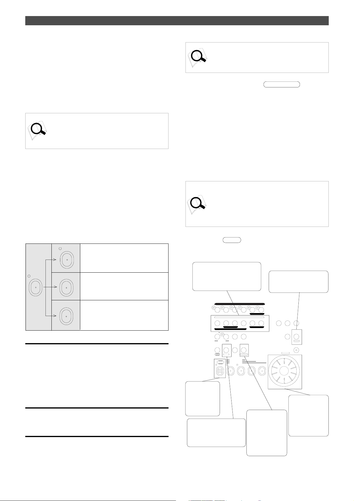
Recording Preparation
The FD-4 does not include recording/playback media.
First you need to connect a SCSI drive and format a disk
so that you can record, play back, and edit on the FD-4.
You may use a removable SCSI drive, such as an MO drive,
EZ drive or a Zip drive. For more information on removable
SCSI disks supported by the FD-4, refer to the “List of the
drives with operation guaranteed” attached to this manual.
FOSTEX does not guarantee data integrity recorded on the
FD-4 using an unlisted removable drive.
<About damages>
Fostex is not responsible for any “direct damage” or “ indirect damage” caused by using the FD-4.
<About copyrights>
It is prohibited law to use any part of a CD recording or video images or audio data for which a copyright is possessed by a third
party for commercial purpose such as contents, broadcasts, sales,
or distribution - any purpose other than for your personal pleasure.
Recording preparation
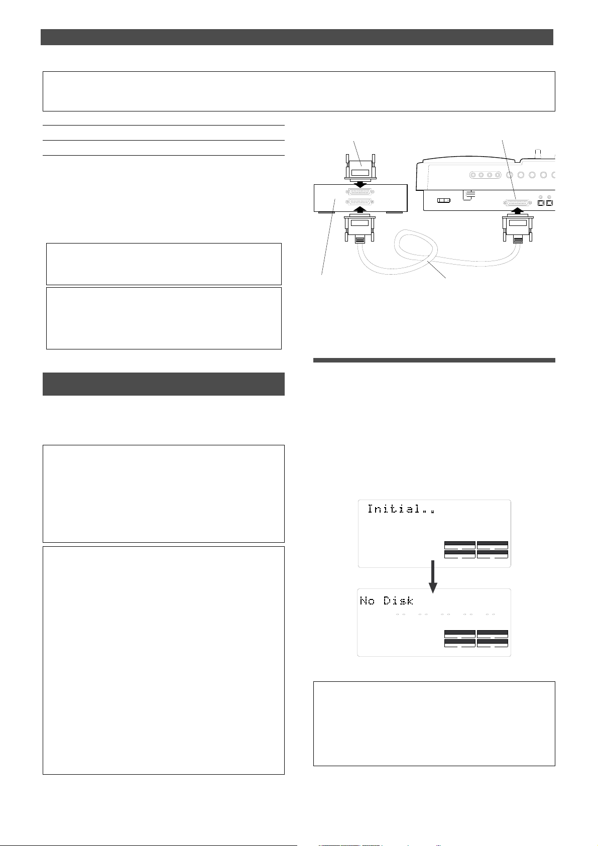
SCSI terminator
SCSI drive
SCSI cable
SCSI connector
• After making the connection, turn on the power
to the FD-4 and the SCSI drive.
Connecting a SCSI drive
Connect a SCSI drive to the SCSI terminal on the FD-4. Refer
to the figure on the right and read the notes and steps
described here to connect the drive.
• Handling a SCSI drive
A SCSI drive and its disk are made of precision parts that are susceptible to strong external impact and magnetic fields. Handle them
carefully . Do not drop them on the floor or place them near a device
that could generate a strong magnetic field (such as a large TV,
speakers, etc.). Read the instruction manual that comes with your
SCSI drive before you try to connect it to the FD-4.
• Notes on connection
1
.
You can connect only one SCSI drive to the FD-4’s SCSI
terminal. Do not “daisy-chain” multiple SCSI drives.
2
.
Install a SCSI terminator on the other connector on the connected
SCSI drive. (If it has a termination switch, be sure to turn the
switch to “terminate” or “on.”)
3
.
Before making the connection, be sure to turn off the power to all
devices.
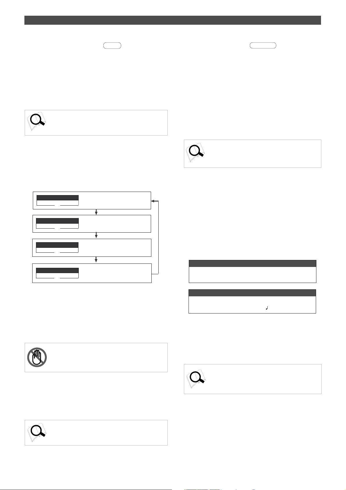
If the connection is made correctly, turning on the power
to both devices will display the “Initial..” message, then the
“No Disk” message. (The following example assumes that a
removable SCSI drive is connected. If a stationary disk is
connected, the [UnFormat ?] message (see the next page)
appears instead of the [No Disk] message.)
This message means that a disk has not been inserted into
the SCSI drive. Follow the steps on the next page to set up
and format the disk so that you can use it to record and
play back.
SYNC OUT
AUTO A.PUNCH
ABS
SMF
SYNC OUT
AUTO A.PUNCH
DRIVE
DRIVE
SCSI
PGM
SCSI
4
.
The FD-4 has a 25-pin female SCSI connector that supports the
Macintosh. Use an appropriate, standard SCSI cable.
Fix the connector of the cable with screws.
5
.
There is no restriction regarding the ID number for a connected
SCSI drive. The FD-4 will automatically recognize and display
the ID number that is set on the SCSI drive.
<Note>
If the “No Drive !” message and the “Initial..” message flash alternately on the display when you turn on the power, the FD-4 cannot
recognize the SCSI drive. Check to see whether all connections
are made correctly, that the power to the SCSI drive is turned on,
and that the cable is not defective.
5
Page 6

Recording preparation
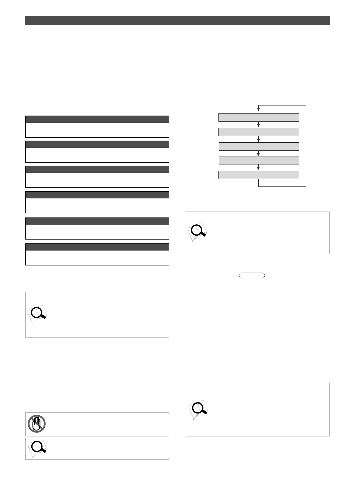
Formatting a new disk
Follow the procedure below to format a new disk.
1/L
START IN OUT
AUTO PUNCH
AUTO RTN
HOLD/ STORE
PGM SEL
VARI
PITCH
SHIFT
P. EDIT
AUTO
PUNCH
RECORD
RECORD TRACK
PREVIEW
AUTO RTN
AUTO PLAY
CLIPBOARD PLAY
LOCATE ABS 0
LOCATE REC END
UNDO/
REDOEDIT
LOCATE
LOC MEM
4/R3/L2/R
ADD. TRACK
END IN OUT
CLIPBOARD
RL
TIME BASE
SETUP
SELDISP SEL
EXIT
EXECUTE
/YES
/NO
ELECT
ACCESS
SHUTTLE
JOG
F FWDREWINDPLAYSTOP
4
5
2
3
5
1. Insert a disk into the SCSI drive.
If you insert an unformatted disk or a disk in an inappropriate formats, the FD-4 recognizes that the disk is
“unformatted,” displays the “Unformat!” message, then
automatically enters SETUP mode, and displays the “Format ?” menu.
At this time, the ID number of the connected SCSI drive will
appear and [SURE ?] will blink on the display. (In the following example, the FD-4 recognizes that the ID number of
the connected SCSI drive is set to [ID 2].)
SYNC OUT
DRIVE
AUTO A.PUNCH
44.1kHz
SETUP
SCSI
Flashing
SURE?
SYNC OUT
DRIVE
AUTO A.PUNCH
SCSI
There are three recording modes (see the following table).
In most cases, select [Normal] (Normal mode) ,which is currently displayed. If you prefer higher quality recording
(CD-level quality with a sampling rate of 44.1kHz), select
“Mastering mode 1” or “Mastering mode 2.” Note that available recording time is shorter in Mastering mode 1 and 2.
<Recording mode>
Recording
mode
Normal mode
Mastering
mode 1
Mastering
mode 2
Sampling
rate
32 kHz
44.1 kHz
44.1 kHz
Quantization
DAC *
16-bit linear
16-bit linear
Available recording
track in real-time
4 Real tracks
+
2 Additional tracks
4 Real tracks
+
2 Additional tracks
4 Real tracks
(See Notes below.)
SETUP
44.1kHz
DRIVE
DRIVE
SCSI
Flashing
SYNC OUT
AUTO A.PUNCH
SURE ?
SYNC OUT
AUTO A.PUNCH
2. Press the EXECUTE/YES key.
The FD-4 displays [Pls Wait !], then immediately displays
the recording mode menu, with [Normal] and [SURE ?] flashing as shown below.
6
(*) Digital Audio Acoustic Coding.
<Notes>
* Y ou can record only to Real tracks on a disk formatted in
Mastering mode 2.
However, you can perform operations other than recording, such
as “T rack Exchange,” using Additional tracks.
For more information, refer to the “Real track and Additional
track” section of the “Before Starting” chapter.
* After you record data on a disk formatted in Normal mode, if you
mix down the data digitally to DAT, copy the data, or save or
load the song data, select “32kHz/SP mode” as a recording mode
for the DAT recorder.
* The FD-4 employs a recording format called “FDMS-3” (Fostex
Disk Management System-3), which is also used on the Fostex
digital master recorder D-160.
Therefore, the D-160 can play back data that was recorded in
Mastering mode 1 or 2 on the FD-4. However, the D-160 can
not play back data recorded in Normal mode.
Page 7
Recording preparation
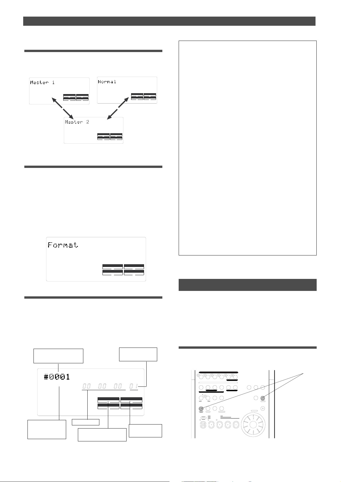
3. Turn the JOG dial to select a recording mode.
Turning the JOG dial counter-clockwise (to the left) will
display the recording mode indication in the order of [Normal] -> [Master 2] -> [Master 1].
SURE?
SYNC OUT
AUTO A.PUNCH
SETUP
44.1kHz
DRIVE
SCSI
44.1kHz
SETUP
SURE?
DRIVE
SYNC OUT
SCSI
AUTO A.PUNCH
SURE?
SYNC OUT
AUTO A.PUNCH
SETUP
44.1kHz
DRIVE
SCSI
4. Press the EXECUTE/YES key while holding
down the RECORD button.
The [Format ?] message lights up on the display, and a negative value of the unformatted disk area size (Megabytes)
will count down as the format operation progresses. All keys
will be disabled during the format operation. Please wait a
while.
When formatting is complete, [COMPLETED !] lights up on
the display, and the FD-4 stops accessing the SCSI disk. The
display looks something like below. (If you have selected
Mastering mode 1 or 2, [44.1kHz] lights up on the display.)
SETUP
<Note 1>
When you format a disk, a Program is named “temporary title.”
You can edit this title as you wish. For more information, refer to “Editing a Program title” of the “Handling Programs” chapter on page 39.
<Note 2>
Formatting will automatically create one Program on the disk. You can
create up to 99 Programs, depending on the available disk space.
You can also select a desired Program from multiple Programs.
For more information, refer to “Managing songs by Program Change
function” in the “Before Starting” chapter on page 25. For more information, refer to “Using a Program Change function” on page 37.
<Note 3>
If you format a disk in Master 1 or Master 2 recording mode, the sampling rate indicator [44.1kHz] lights up. If you select Normal mode,
nothing lights up.
<Note 4>
After formatting the disk, the FD-4 automatically selects ABS as Time
Base. You can select ABS, MTC time, or BAR/BEA T/CLK as the Time
Base. For more information, refer to the “Display Section” in the “Names
and Functions” chapter on page 21.
<Note 5>
The indicated “SYNC OUT” setting ([CLK]) means that clock signals
(MIDI clock signal and Song Position Pointer) are output as a sync
signal from the FD-4’s MIDI OUT connector to an external MIDI device. You may change this setting, if necessary, when you are using
the FD-4 to sync with an external MIDI device. For more information,
refer to “SYNC OUT setting” in the “Changing the Initial Settings” chapter on page 86.
COMPLETED
SYNC OUT
CLK
AUTO A.PUNCH
DRIVE
!
SCSI
5. Press the STOP button or the EXIT/NO key .
Press the STOP button or the EXIT/NO key to exit SETUP
mode. The Time Base will change to ABS (ABS 0 appears).
Formatting will automatically create one Program on the
disk (PGM 01), and display its title (#0001). (This title also
appears whenever you insert a formatted disk in the SCSI
drive.) The display indicators mean the following:
“T emporary title” for
Program 1 (See Note 1.)
ABS
ABS is selected as
Time Base. (See
Note 4.)
SYNC OUT
CLK
ABS time 0
The default setting of
SYNC OUT (See Note 5.)
Program number
(See Note 2.)
44.1kHz
SMF
AUTO A.PUNCH
DRIVE
PGM
SCSI
The current drive
is a SCSI drive.
Now that you completed connecting the SCSI drive and formatting the disk, you can start recording and playing back.
Removing a disk from the SCSI drive
If a removable disk is inside the SCSI drive, you cannot
eject it using the eject switch on the drive. Follow the procedure below using the key on the control panel of the FD-4
to eject the disk.
1. Press the EXIT/NO key while holding down
the SHIFT key.
The disk is ejected from the SCSI drive and [No Disk] appears on the display.
1/L
START IN OUT
AUTO PUNCH
AUTO RTN
HOLD/ STORE
PGM SEL
VARI
PITCH
SHIFT
P. EDIT
AUTO
PUNCH
RECORD
RECORD TRACK
AUTO RTN
AUTO PLAY
CLIPBOARD PLAY
LOCATE ABS 0
LOCATE REC END
PREVIEW
4/R3/L2/R
END IN OUT
CLIPBOARD
UNDO/
REDOEDIT
LOCATE
LOC MEM
ADD. TRACK
RL
TIME BASE
SETUP
SELDISP SEL
EXIT
EXECUTE
/YES
/NO
ELECT
ACCESS
SHUTTLE
JOG
F FWDREWINDPLAYSTOP
1
7
Page 8
Recording preparation
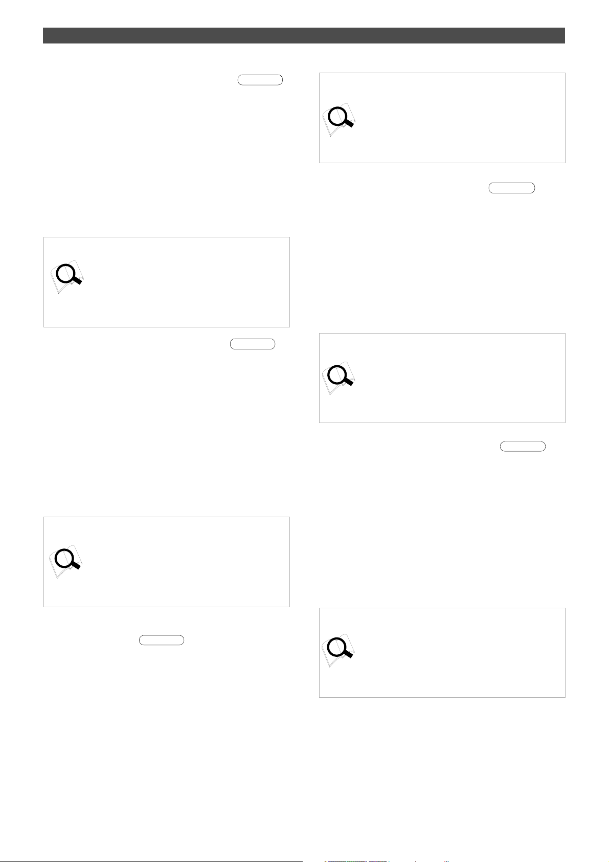
Formatting the disk again
If you wish to change the recording mode of a formatted
disk or to re-format a used disk, you need to set the FD-4 to
SETUP mode and use the [Format ?] menu.
In the following procedure, we assume that the power to
the FD-4 and the SCSI drive is already turned on.
1. Insert a disk into the SCSI drive.
When you insert a formatted disk into the SCSI drive, the
FD-4 displays the recording mode of the disk (Master 1,
Master 2, or Normal) and the type of Time Base that was
used previously.
1/L
START IN OUT
AUTO PUNCH
AUTO RTN
HOLD/ STORE
PGM SEL
VARI
PITCH
SHIFT
P. EDIT
AUTO
PUNCH
RECORD
RECORD TRACK
PREVIEW
AUTO RTN
AUTO PLAY
CLIPBOARD PLAY
LOCATE ABS 0
LOCATE REC END
LOC MEM
4/R3/L2/R
ADD. TRACK
END IN OUT
CLIPBOARD
UNDO/
REDOEDIT
LOCATE
RL
TIME BASE
SETUP
SELDISP SEL
EXIT
EXECUTE
/YES
/NO
ELECT
ACCESS
SHUTTLE
JOG
F FWDREWINDPLAYSTOP
2
8
4, 5, 7
3, 6
8
7
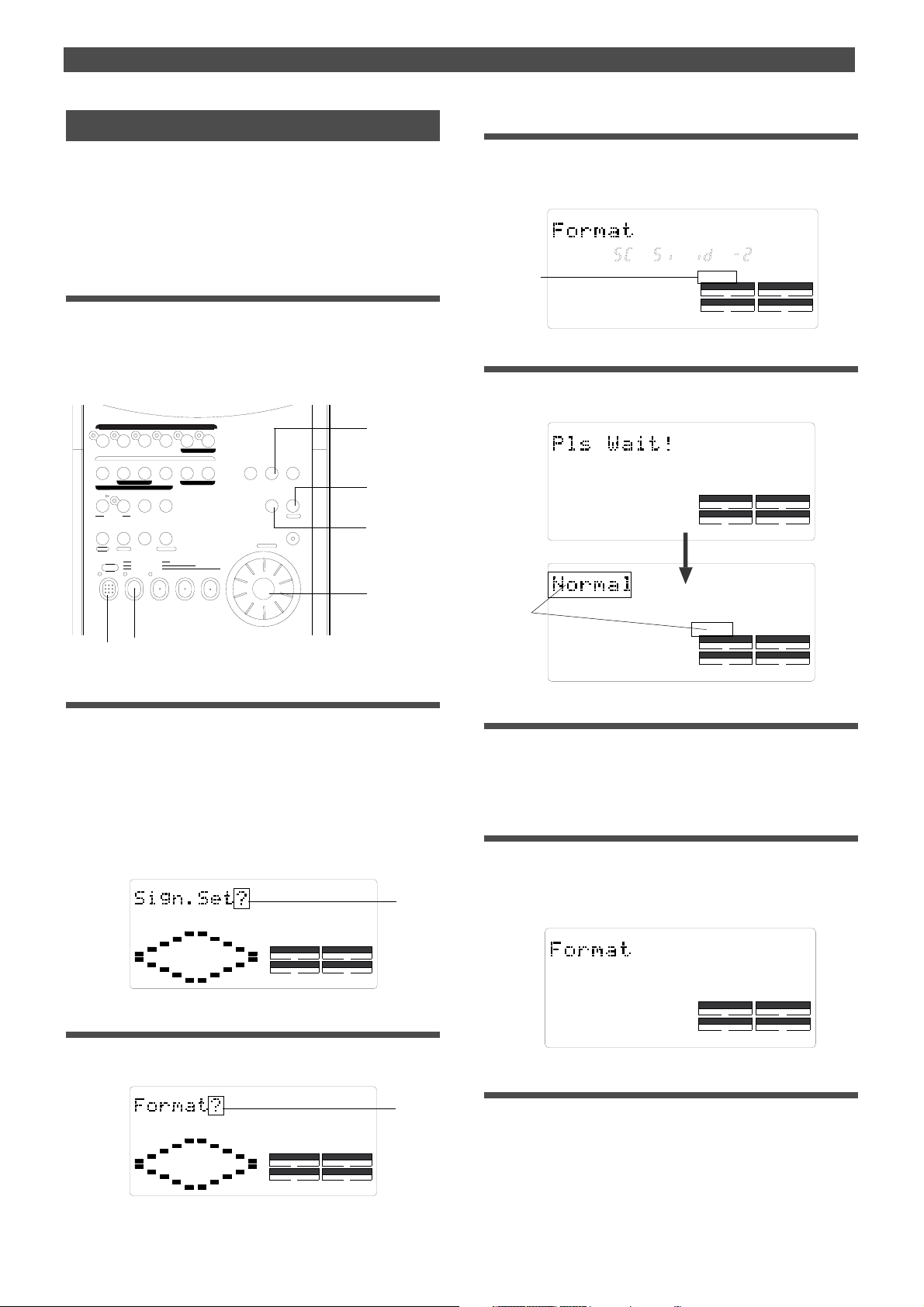
4. Press the EXECUTE/YES key.
As explained in the “Formatting a new disk” section, the ID
number of the connected SCSI drive appears and [SURE ?]
flashes on the display.
44.1kHz
SETUP
Flashing
SURE ?
SYNC OUT
CLK
AUTO A.PUNCH
DRIVE
SCSI
5. Press the EXECUTE/YES key again.
[Pls Wait !] appears momentarily, then the recording mode
selection display appears.
SETUP
44.1kHz
DRIVE
DRIVE
SCSI
SCSI
Flashing
SYNC OUT
AUTO A.PUNCH
SURE?
SYNC OUT
CLK
AUTO A.PUNCH
2. Press the SETUP key .
The FD-4 enters SETUP mode and displays the first layer, in
which you can select the desired SETUP menu.
If the FD-4 enters SETUP mode after you format a disk or
turn on the power and insert a disk, the FD-4 displays the
first layer of the [Sign. Set ?] (signature setting) menu as
shown below. (“?” flashes.)
Otherwise, the FD-4 displays the first layer of the menu
that was shown before the FD-4 exited SETUP mode.
44.1kHz
SETUP
SYNC OUT
CLK
AUTO A.PUNCH
DRIVE
Flashing
SCSI
3. Turn the JOG dial and select [Format ?].
You can also use the HOLD/> key, REWIND button, or F
FWD button to select the [Format ?] menu.
44.1kHz
SETUP
Flashing
6. Use the JOG dial to select a recording mode.
Refer to the “Formatting a new disk” section for more information on recording modes.
7. Press the EXECUTE/YES key while holding
down the RECORD button.
The FD-4 starts formatting the disk in selected recording
mode. Wait a while. When formatting is complete, [COMPLETED !] lights up on the display, and the FD-4 stops accessing the disk.
SETUP
COMPLETED
SYNC OUT
CLK
AUTO A.PUNCH
DRIVE
!
SCSI
8. Press the STOP button or the EXIT/NO key.
The FD-4 exits SETUP mode and displays ABS 0.
SYNC OUT
CLK
AUTO A.PUNCH
DRIVE
SCSI
8
Page 9
INPUT 3
R MON OUT L
R ST OUT L
AUX RTN 1
R MONO/L
AUX RTN 2
R MONO/L
2 AUX SEND 1
4 INSERT 3
INPUT 4
SCSI
OUTIN
DATA
R
RECORDER IN
LIN
MIDI
OUT
PUNCH
IN/OUT
DATA
MIDI
POWER
Rear panel
Control panel
Names and Functions
Names and Functions
AUX
AUX1
AUX2
EQ
HIGH
0
-
+
MID
GAIN
0
-
+
MID
SHIFT
900
300
200
5k
LOW
0000
-
+
MON MON MON MON
0
TRK1INPUT
PAN
PAN PAN PAN
L
R
INPUT
OFF
TRK 1
1
10
5
0
AUX
00
AUX1
AUX2
EQ
HIGH
0
-
+
MID
GAIN
0
-
+
MID
SHIFT
900
300
2k
200 5k
LOW
-
+
000
TRK2INPUT
PAN
MON L MON RMON L MON R
L
R
INPUT SELINPUT SEL INPUT SEL
INPUT
OFF
TRK 2
2 3 4
10
5
0
AUX
0
AUX1
AUX2
EQ
HIGH
0
-
+
MID
GAIN
0
-
+
MID
SHIFT
900
2k
300
200 5k
LOW
-
+
TRK3INPUT
PAN
MON L MON R
L
R
INPUT
OFF
TRK 3
10
5
0
AUX1
HIGH
MID
GAIN
MID
SHIFT
2k
300
200 5k
LOW
-
PAN
MON L MON R
L
INPUT SEL
10
5
0
H
M
L
LEVEL LEVEL
AUX
0
EQ
0
0
900
PAN
INPUT
TRK 4
AUX RTN
AUX2
1
+
0
10
2
+
010
2k
PGM SEL
AUTO
PUNCH
RECORD
P. EDIT
VARI
PITCH
AUTO PUNCH
AUTO RTN
CLIPBOARD PLAY
LOCATE ABS 0
LOCATE REC END
RECORD TRACK
AUTO RTN
AUTO PLAY
PREVIEW
4/R3/L2/R
ADD. TRACK
END IN OUT
CLIPBOARD
UNDO/
REDOEDIT
LOCATE
LOC MEM
DIGITAL MULTITRACKER
RL
TIME BASE
SETUP
SELDISP SEL
EXIT
EXECUTE
/YES
/NO
ELECT
ACCESS
SHUTTLE
JOG
F FWDREWINDPLAYSTOP
1/L
+
MON SECTION
TRK4INPUT
MASTER
010
R
SELECTOR
L/R
OFF
L/R+MON
MON
L/R
10
5
0
H
M
L
START IN OUT
HOLD/ STORE
SHIFT
Front panel
21
3
4
9
Page 10

Names and Functions
Control Panel (Mixer Section)
AUX
AUX
AUX1
AUX1
7
6
5
4
3
2
1
AUX2
EQ
HIGH
HIGH
0
-
-
+
MID
MID
GAIN
GAIN
0
-
-
+
MID
MID
SHIFT
SHIFT
300
200
LOW
-
PAN
L
1
10
5
0
900
900
300
2k
200 5k
5k
LOW
0000
-
+
MON MON MON MON
0
TRK1INPUT
PAN
MON L MON RMON L MON R
PAN PAN PAN
L
R
INPUT SELINPUT SEL INPUT SEL
INPUT
OFF
TRK 1
2 3 4
10
5
0
Letters in brackets ([ ]) are labels on the panel.
AUX RTN
AUX
AUX
00
AUX1
AUX2
EQ
HIGH
0
-
+
MID
GAIN
0
-
+
MID
SHIFT
900
2k
300
200 5k
LOW
-
+
000
TRK2INPUT
PAN
MON L MON R
L
R
INPUT
OFF
TRK 2
10
5
0
0
AUX2
EQ
HIGH
0
+
MID
GAIN
0
+
MID
SHIFT
2k
LOW
+
TRK3INPUT
PAN
R
INPUT
OFF
TRK 3
H
M
L
LEVEL LEVEL
AUX1
-
-
900
300
200 5k
-
MON L MON R
PAN
L
INPUT SEL
10
5
0
0
AUX2
EQ
0
1
+
0
0
INPUT
TRK 4
10
2
+
010
2k
+
MON SECTION
TRK4INPUT
MASTER
010
R
SELECTOR
L/R
L/R+MON
OFF
MON
L/R
10
5
0
H
M
L
1/L
START IN OUT
AUTO PUNCH
AUTO RTN
HOLD/ STORE
PGM SEL
VARI
PITCH
SHIFT
P. EDIT
CLIPBOARD PLAY
AUTO
LOCATE REC END
PUNCH
RECORD
RECORD TRACK
AUTO RTN
AUTO PLAY
LOCATE ABS 0
4/R3/L2/R
PREVIEW
END IN OUT
UNDO/
REDOEDIT
LOCATE
LOC MEM
ADD. TRACK
CLIPBOARD
DIGITAL MULTITRACKER
8
RL
TIME BASE
SETUP
SELDISP SEL
EXIT
EXECUTE
/YES
/NO
ELECT
ACCESS
SHUTTLE
JOG
F FWDREWINDPLAYSTOP
9
10
12
11
1. Input faders [1-4]
These faders allow you to control the input level of signals
selected via the INPUT SEL switch [2] (that is, the input
signals from the INPUT jacks or the recorder output signals).
Nominal level is obtained at fader position of 7-8, and the
fader achieves approximately 6dB of gain at the 10 position.
2. Input select switches [INPUT SEL (INPUT/OFF/TRK)]
These switches allow you to select signals to be routed to
the input faders. The following options are available:
“INPUT” Signals from instruments and microphones connected
to the INPUT jacks are routed to the channel faders.
“OFF” The switch is turned off. No signals are routed.
“TRK” Recorder output signals (TRK 1-4) are routed to the
channel faders, with Track 1 output routed to Channel 1,
Track 2 routed to channel 2, etc.
3. Panpot knobs [PAN (L/R)]
Panpot knobs have the following two functions:
During recording, you can use them to pan channel signals of the
sound sources connected to the INPUT jacks to Tracks 1-4 (or
Tracks 5 and 6). T urn the knobs all the way to L or R. If you turn the
1
knob to L, the corresponding channel signal is recorded to Tracks
1 and 3 (and 5). If you turn the knob to R, the corresponding channel
signal is recorded to Tracks 2 and 4 (and 6). (Tracks 5 and 6 are
available only in Mastering mode 1 and Normal mode.)
For mixdown, use these knobs to determine the stereo image of
2
the playback sound of Tracks 1-4. Turn the knobs to the desired
position.
4. Monitor panpot knobs [P AN (MON L/MON R)]
These knobs allow you to adjust the balance of the signals
that were level-adjusted for the level via the MON knob [5]
before you send them to the monitor section L and R. The
following options are available.
“MON L” The signal routed to the MON knob will be sent only to
monitor section “L.”
“Center” The signal routed to the MON knob will be sent to both
monitor section “R” and “L” at the same level.
“MON R” The signal routed to the MON knob will be sent only to
monitor section “R.”
10
Page 11
Names and Functions
5. Monitor level control knob [MON (INPUT/TRK)]
These knobs are used to select signals sent to monitor
sections L and R, and to adjust the level of those signals.
The following options are available.
“TRK” The recorder output signals are sent to the monitor
section. As you turn the knob to the right, the signal
level becomes higher.
“0” No signals are sent.
“INPUT” Pre-fader signals* from the INPUT jacks are sent to the
monitor section. As you turn the knob to the left, the signal
level becomes higher.
* Pre-fader signal: Input signals before reaching the input faders
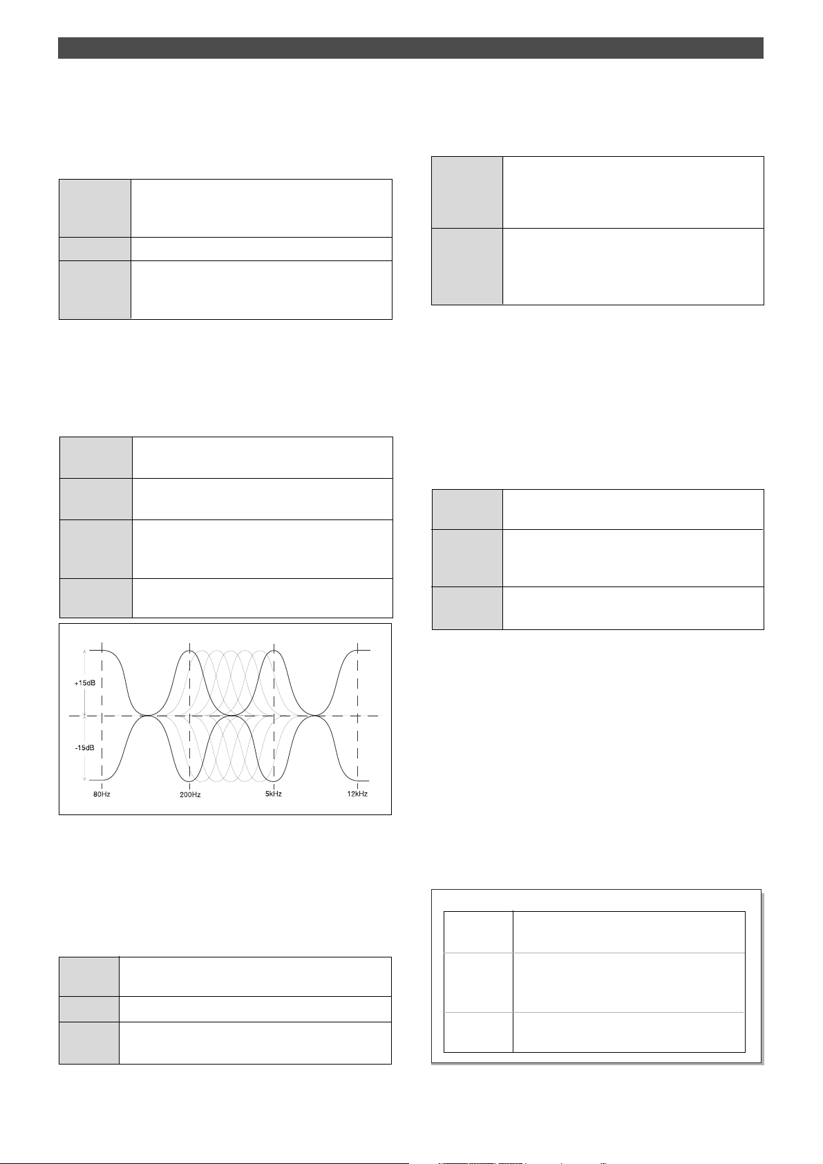
6. Equalizer control knobs [EQ (HIGH/MID/LOW)]
These knobs are used to adjust tonal quality of the signals
routed to the channel faders. The following settings are
available.
“HIGH” Signals with a frequency of 12kHz will be boosted/cut up
to +/-15dB.
“MID GAIN” The frequency range selected via the MID SHIFT knob
(200Hz-5kHz) will be boosted/cut up to +/-15dB.
“MID SHIFT” Use this setting to select a frequency range to boost or
cut using the MID GAIN knob. You can set the frequency
in the range of 200Hz-5kHz.
“LOW” Signals with a frequency of 80Hz will be boosted/cut up
to +/-15dB.
8. AUX return knobs [AUX RTN (1, 2)]
These knobs allow you to adjust the input level of processed
signals from a connected external effect unit.
AUX RTN 1 These knobs enable you to adjust the input level of
processed signals from an external effect unit connected
to the AUX RTN jack 1. The level of both signals input to
AUX RTN 1 L/MONO and R will be adjusted equally.
AUX RTN 2 These knobs enable you to adjust the input level of
processed signals from an external effect unit connected
to the AUX RTN jack 2. The level of both signals input to
AUX RTN 2 L/MONO and R will be adjusted equally.
9. Monitor master knob [MONITOR SECTION (MASTER)]
This knob allows you to adjust the final level of monitoring
signals, that is, the headphone volume and the level of signals
output from the MON OUT L/R jacks.
10. Monitor select switch
[SELECTOR (L/R, L/R+MON, MON)]
This switch allows you to select a signal to be routed to the
MON OUT L/R and PHONES jacks. The following options
are available.
“L/R” This selects signals output from the STEREO OUT L/R
jacks (stereo bus L/R signals).
“L/R+MON” This selects both signals output from the STEREO OUT
L/R jacks and signals routed to channel monitor buses
L/R.
“MON” This selects signals routed to channel monitor buses L/
R.
7. AUX send knobs [AUX (AUX 1/AUX 2)]
These knobs are used to select whether the channel fader
signals are output from the AUX SEND 1 jack or AUX SEND
2 jack, and to adjust the level of those signals. That is, the
signals selected and adjusted via these knobs will be sent
from the AUX SEND jack 1 or 2 to an external device, such
as an effect unit.
“AUX 1” Signals are sent to the AUX SEND jack 1. T urning the knob
to the left will increase the output level.
“0” No signals are sent.
“AUX 2” Signals are sent to the AUX SEND jack 2. T urning the knob
to the right will increase the output level.
1 1. Master fader [L/R]
The master fader allows you to adjust the level of signals
output from the STEREO OUT L/R jacks (stereo bus L/R
output signal). The fader setting will affect the level of
recorder input signals.
12. Input level switches [LEVEL (H/M/L)]
Set these switches to appropriate positions according to the
output level of the devices connected to input jacks 3 and 4
(the phone jacks on the front panel or the XLR connector
on the rear panel).
Connect a microphone or other low-output device to input
jacks 3 and 4 (on the front panel or rear panel) that have
the input level switch. Refer to the example below.
<Example>
“L (-50dB)” Set the switch to this position when you connect
a microphone.
“M (-30dB)” Set the switch to this position when you connect
a single-coil or humbucking type electric guitar or
bass.
“H (-10dB) Set the switch to this position when you connect
a keyboard or drum machine.
11
Page 12
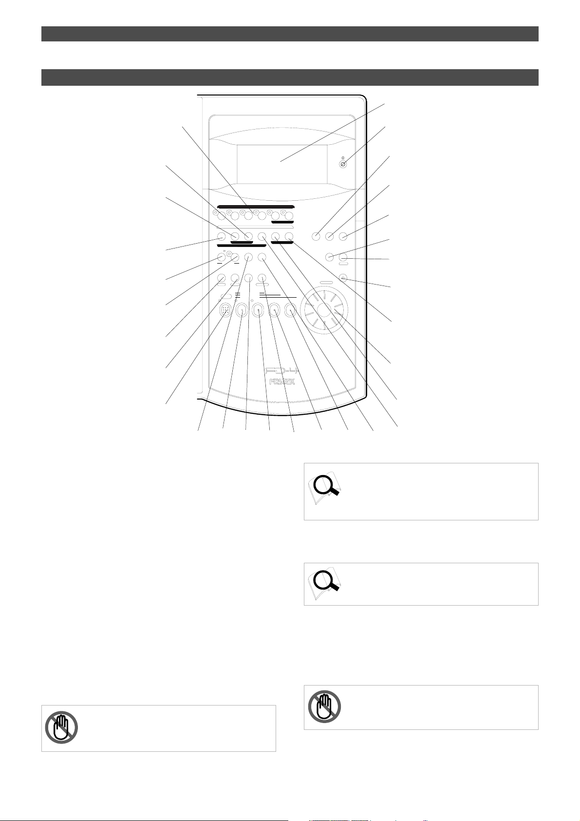
Names and Functions
Control panel (Recorder Section)
13
14
15
39
38
36
32
33
28
29
27
1/L
START IN OUT
AUTO PUNCH
AUTO RTN
HOLD/ STORE
PGM SEL
VARI
PITCH
SHIFT
P. EDIT
CLIPBOARD PLAY
AUTO
PUNCH
LOCATE REC END
RECORD
RECORD TRACK
AUTO RTN
AUTO PLAY
LOCATE ABS 0
4/R3/L2/R
PREVIEW
END IN OUT
UNDO/
REDOEDIT
LOCATE
LOC MEM
ADD. TRACK
CLIPBOARD
DIGITAL MULTITRACKER
16
17
RL
18
TIME BASE
SELDISP SEL
SETUP
EXIT
EXECUTE
/YES
/NO
ELECT
ACCESS
SHUTTLE
JOG
19
20
21
F FWDREWINDPLAYSTOP
41
22
40
35
26
30
25
13. Record track select keys
[RECORD TRACK (1/L, 2/R, 3/L, 4/R, L, R)]
These keys enable you to select “SAFE” or “READY” for a
recording track. Pressing the key once will cause the
corresponding track to enter READY mode, and the LED of
the key you pressed to flash. Pressing the key again will
cause the corresponding track to enter “SAFE” mode, and
the LED to turn off.
The indication; 1/L, 2/R, 3/L, 4/R are for Real tracks, and L
and R are for Additional tracks 5 and 6.
When you start recording on a track in READY mode, the
flashing LED remains lit steadily.
If you press only the RECORD button with a track in READY
mode, you can monitor the signal input to the READY track
so that you can adjust the recording level. To cancel this
input monitoring status, press the RECORD button again.
(This causes the FD-4 to enter playback monitoring mode.)
You can also use these select keys to select tracks to edit for
Copy & Paste, Move & Paste, Erase, etc.
<Note>
You can record on Additional tracks in real-time only when
recording mode is “Normal mode” or “Mastering mode 1.”
31
24
23
Refer to page 26 for more information on playback monitoring
and input monitoring.
Refer to page 28 for more information on using the RECORD
TRACK select keys.
34
37
14. LCD
The LCD indicates signal levels and various settings.
Refer to “Display Section” on page 20 for more information
on the display.
15. Contrast adjustment knob
Use this knob to adjust the contrast of the LCD. Turning
this knob clockwise will increase the contrast, and turning
it counter-clockwise will decrease the contrast.
<Note>
The display is not illegible if you leave the knob counterclockwise all the way.
12
Page 13
Names and Functions
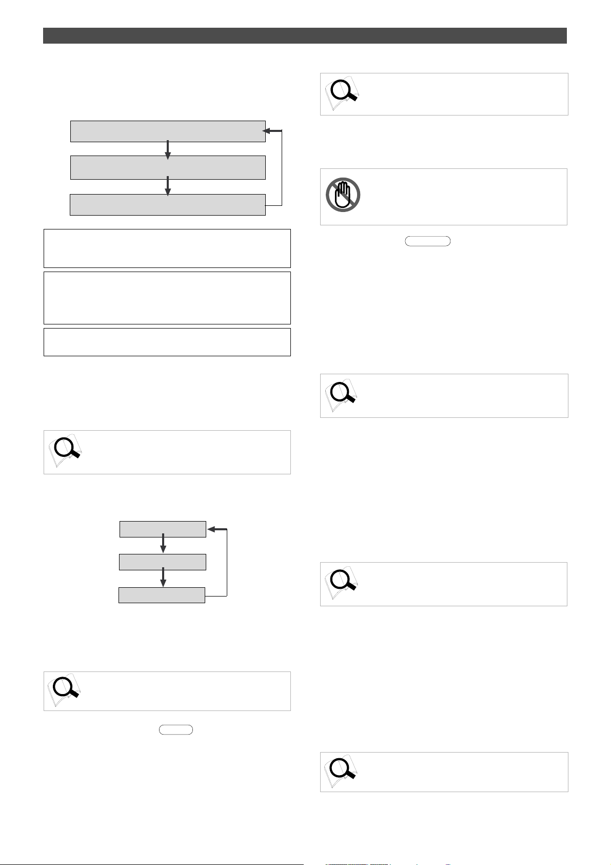
16. Display indication select key
Pressing this key each time will change the display indication
as follows:
Currently-selected Time Base indication *1
Currently-selected Time Base REMAIN indication *2
External MTC IN indication *3
*1 The current position in terms of Time Base selected via the TIME
BASE SEL key appears. ABS time, MTC time, or BAR/BEAT/CLK is
used.
*2 Available recording time and space on the current SCSI disk appears.
Time indication uses the currently-selected Time Base (ABS, MTC, or
BAR/BEAT/CLK). The space indication uses MB (Megabyte). (The
values are based on mono track recording.)
*3 MTC being input from an external MIDI device to the FD-4 appears.
If no MTC is input, the display shows “00H 00M 00S 00F.”
17. Setup key [SETUP]
Press this key to set the FD-4 in SETUP mode to execute
various menus. This key works only when the FD-4 is
stopped.
Refer to page 81 for more information on SETUP mode.
18. Time Base select key
Pressing this key repeatedly will switch Time Base as follows:
ABS time
BAR/BEA T/CLK
MTC time
Refer to pages 7, 56 and 81 for more information on the
operation of this key .
21. Access LED [ACCESS]
This LED lights up or flashes when data is being written to
or read from an external SCSI drive disk.
<Note>
Do not turn off the power to the unit when this LED lights up
or flashes. Otherwise you may lose data on the hard disk
connected to the unit.
22. JOG dial [JOG/
When the FD-4 is stopped, use the JOG dial to perform a jog
operation (forward or reverse) for audio scrubbing without
pitch change. You can also use this dial to increase and
decrease the numeric values or input alphabetical characters
in edit mode.
Rotating the JOG dial while holding down the SHIFT key
will enable you to perform the shuttle operation with
different speeds ranging from normal speed to 64-times
speed.
Refer to page 62 for more information on the cue/review
function and the shuttle function.
SHUTTLE
]
23. Fast forward button [F FWD]
Pressing this button while the FD-4 is stopped will start fast
forwarding at low speed at first, then gradually accelerate
to 30-times speed. If you press this button while the FD-4 is
playing, cueing (fast forwarding with sound) starts at threetime speed. Pressing this button while holding down the
STOP button will activate the “LOCATE REC END” operation,
which will locate the end point of the recording on the Real
track in the current Program. You can also use this button
to locate an edit point in edit mode.
Refer to the “STOP button” section and page 66 for more
information on the “LOCATE ABS 0” operation.
19. Execute/Yes key [EXECUTE/YES]
Press this key to confirm the edit operations, such as Copy
& Paste, Move & Paste, and Erase, and to set the parameters
of SETUP menus.
Refer to pages 56 and 81 for more information on the
operation of this key.
20. Exit/No key [EXIT/NO/
This key is the counterpart of the EXECUTE/YES key.
Press this key to cancel an operation. When you use a
removable SCSI disk, pressing this key while holding down
the SHIFT key will eject the disk.
EJECT
]
24. Rewind button [REWIND]
Pressing this button while the FD-4 is stopped will start
rewinding at low speed at first, then gradually increase the
speed up to 30-times speed. If you press this button while
the FD-4 is playing, cueing (rewinding with sound) starts at
three-times speed. Pressing this button while holding down
the STOP button will activate the “LOCATE ABS 0” operation,
which will locate the beginning of the current Program (ABS
time: 00m 00s 00f). You can also use this button to locate
an edit point in edit mode.
Refer to the “STOP button” section and page 66 for more
information on the “LOCATE ABS 0” operation.
13
Page 14
Names and Functions
25. Play button [PLA Y]
Pressing this button causes the recorder section to play back.
Pressing this button while holding down the RECORD button
when a track is in READY mode will cause the FD-4 to start
recording on the READY track.
Pressing only this button during the recording operation
will punch-out (cancel) recording. Pressing this button while
holding down the STOP button will cause the “CLIPBOARD
PLAY” operation to start.
* Refer to the “STOP button” section and page 57 for more
information on the “CLIPBOARD PLAY” operation.
* Refer to page 48 for more information on the Punch Out
operation using the PLAY button.
26. Stop button [ST OP]
Pressing this button during the playback, recording, fast
forward, or rewind operation will stop the recorder transport
operation. Pressing this button while the FD-4 is in SETUP
mode will cause the unit to exit SETUP mode.
Pressing the PLAY, REWIND, or F FWD button while holding
down the STOP button will cause the following operations
to start.
If you wish to rehearse the Manual Punch In/Out operation
using the foot switch, press the foot switch while holding
down this button to enter Rehearsal mode.
PLAY
“CLIPBOARD PLAY” operation starts. (See
below.) . During the operation, the STOP
LED flashes and the PLAY LED lights up.
STOP
REWIND
ABS 0 is located. (See below.)
* Refer to pages 57 and 66 for more information on these
operations.
* Refer to page 46 for more information on the Punch In/Out
operation using a foot switch.
27. Record button [RECORD/
AUTO PUNCH
]
Pressing the PLAY button while holding down this button
will cause the FD-4 to start recording on any READY tracks.
At this time, the flashing LED of the RECORD TRACK select
key for the corresponding READY track lights up steadily,
and the PLAY LED and the RECORD LED light up.
If you press only the RECORD button, a READY Real track
enters input monitoring mode (The RECORD LED flashes.).
At this time, pressing the RECORD button again will cancel
the input monitoring mode, and the track will return to
playback monitoring mode.
Pressing the RECORD button while holding down the SHIFT
key will toggle between AUTO PUNCH on and off.
* Refer to page 28 for more information on recording.
* Refer to page 43 for more information on AUTO PUNCH
mode.
* Refer to page 26 for more information on input monitoring
and playback monitoring.
28. Shift key [
SHIFT
]
Press a key, button, or turn the dial while holding down the
SHIFT key to activate the following “shift-invoked” functions.
You can audition the data at edit points
(locate points) stored in the memory
keys. (For more information, refer to
“Preview function” on page 69.)
The removable SCSI disk is
ejected. (Refer to “Recording
Preparation” on page 7.)
F FWD
REC END is located. (See below.)
* CLIPBOARD PLAY operation
The CLIPBOARD PLAY operation plays back data on the clipboard. (If the
clipboard does not contain any data, the display shows [Void Data !] and
nothing happens.). During this operation, the display indicates the type of
the data (“Copy Clip” for copy data, and “Move Clip” for move data), and the
duration. The indicator of the copy source or move source track flashes.
In this way, you will know which track the currently playing data comes from
and why the data is on the clipboard.
* ABS 0 locate operation
This operation locates the beginning of the current Program (ABS time:
00m 00s 00f).
* REC END locate operation
This operation locates the end of the audio recording (REC END) on the
Real track in the current Program.
14
RECORD TRACK
1/L
START IN OUT
AUTO PUNCH
AUTO RTN
HOLD/ STORE
PGM SEL
AUTO RTN
VARI
AUTO PLAY
PITCH
SHIFT
P. EDIT
CLIPBOARD PLAY
LOCATE ABS 0
AUTO
PUNCH
LOCATE REC END
RECORD
Auto Punch mode
is turned on and
off. (Refer to
“Punch In/Out” on
page 43.)
You can edit Vari Pitch data.
(Refer to “Playback in Vari Pitch
mode” on page 40 for more
information.)
4/R3/L2/R
ADD. TRACK
PREVIEW
END IN OUT
CLIPBOARD
UNDO/
REDOEDIT
LOCATE
LOC MEM
You can edit locate
data stored in the
LOCATE key. (Refer
to “Storing an edit
point (locate point)” on
page 63 for more
information.
RL
TIME BASE
SELDISP SEL
SETUP
EXIT
EXECUTE
/YES
/NO
ELECT
ACCESS
SHUTTLE
JOG
F FWDREWINDPLAYSTOP
The SHUTTLE dial
function is activated.
(Refer to “JOG dial/
SHUTTLE dial
cueing” on page 62 for
more information.)
Page 15
Names and Functions
AUTO
29.Vari Pitch key [VARI PITCH/
P.EDIT
]
This key toggles Vari Pitch mode on and off. When Vari Pitch
mode is on, the “VARI PITCH” indicator lights up on the
display, and the FD-4 plays using the current pitch data.
Pressing the VARI PITCH key while holding down the SHIFT
key will cause the FD-4 to enter edit mode, in which you can
change pitch data in real-time.
To exit edit mode, press the EXIT/NO key.
Refer to page 40 for more information on playing with Vari
Pitch and editing Vari Pitch data.
30.Auto Return/Auto Play mode on/off key
[AUTO RTN/AUTO PLAY]
Use this key to turn on and off Auto Return mode, Auto Play
mode, and Auto Repeat mode. Each time you press the key,
the mode will change and the following indication will be
displayed.
Auto Return/Play mode is OFF.
(No indication)
AUTO
PLAY
AUTO
RTN
Auto Play mode is ON.
(“PLAY” lights up.)
Auto Return mode is ON.
(“RTN” lights up.)
31. Locate key [LOCATE/
LOC MEM
]
Use this key to locate a point. Press a key that stores locate
points, such as the CLIPBOARD IN/OUT keys, AUTO PUNCH
IN/OUT keys, and AUTO RTN START/END keys, then press
the LOCATE key to locate a point stored in the
corresponding key.
The last locate data will replace the data stored in the
LOCATE key. Therefore, pressing only the LOCATE key will
locate the last locate point. If you have set Auto Play mode,
the FD-4 will start playing from the located point.
Pressing the LOCATE key while holding down the SHIFT
key will cause the FD-4 to enter edit mode, in which you
can edit data stored in the LOCATE key.
Refer to page 66 for more information on the Locate function.
Refer to page 63 for more information on editing data using
the LOCATE key.
32. Hold/> key [HOLD/>]
Pressing the HOLD/> key while the recorder is operating
will cause the FD-4 to capture the time at which you pressed
the key (or bar/beat/clock value), display it, then enter
edit mode. (If you press the HOLD/> key while the recorder
section is stopped, the FD-4 enters edit mode directly.)
To cancel edit mode, press the STOP button, DISP SEL key,
or the EXIT/NO key.
In edit mode, you can use this key to select a digit of the
value to edit (edit point). You can select a digit which flashes
on the display) in the following order.
AUTO
PLAY RTN
* Auto Play mode
The FD-4 locates a point and starts playing from the locate point.
* Auto Return mode
When the AUTO RTN END point is reached while the recorder section is
playing, the FD-4 automatically locates the AUTO RTN START point.
This mode is effective only if the AUTO RTN START point and the AUTO
RTN END point have already been specified.
<Note>
The Auto Return function is enabled only when the FD-4 is
playing. While the FD-4 is recording, the FD-4 will not locate
the STAR T point after it reaches the AUTO R TN END point.
*Auto Repeat mode
This mode is effective only when Auto Play mode and Auto Return mode are
turned on. The FD-4 will play the part between the AUTO RTN ST AR T point
and the AUTO RTN END point repeatedly. This mode is also effective only if
the AUTO RTN START point and the AUTO RTN END point have already
been specified.
Auto Repeat mode is ON.
(Both “PLAY” and “R TN” light up.)
ABS or MTC is used as Time Base:
First, “S” (second) flashes. Each time you press the HOLD/> key,
the flashing characters change in this order: F -> SF -> H -> M-> S.
BAR/BEAT/CLK is used as T ime Base:
First, “BAR” flashes. Each time you press the HOLD/> key, the
flashing indicator changes in this order: -> CLK -> BAR.
If you press the HOLD/> key and the STORE key simultaneously
while the recorder is stopped, the FD-4 enters Program Select
mode, in which you can select a Program or set up a new
Program.
Refer to page 63 for more information on editing memory.
Refer to page 37 for more information on the Program Select
function.
Refer to page 66 for more information on each mode.
15
Page 16
Names and Functions
33. Store key [STORE]
This key is used to store time values (or bar/beat/clock
values) in the memory keys. Press this key, then one of the
following keys to store data indicated on the display
(including edit data) in the corresponding memory key. If
you press the STORE key and the HOLD/> key
simultaneously while the recorder is stopped, the FD-4 enters
Program Select mode, in which you can select a Program or
set up a new Program.
Press the STORE key, and press the CLIPBOARD IN key .
The CLIPBOARD IN point is stored.
This data can be used as locate data.
Press the STORE key, and press the CLIPBOARD OUT key .
The CLIPBOARD OUT point is stored.
This data can be used as locate data.
Press the STORE key, and press the AUT O PUNCH IN key.
The AUTO PUNCH IN point is stored.
This data can be used as locate data.
Press the STORE key, and press the AUTO PUNCH OUT key .
The AUTO PUNCH OUT point is stored.
This data can be used as locate data.
Press the STORE key, and press the AUTO R TN START key.
The AUTO RTN START point is stored.
This data can be used as locate data.
35. Edit key [EDIT]
Pressing this key causes the FD-4 to enter menu selection
mode for editing tracks, and displays the title of the menu
you used last time. Press this key repeatedly or turn the
JOG dial to select a menu. The edit menus appear in the
following order. To execute a desired menu, select the menu,
then press the EXECUTE/YES key.
To exit selection mode, press the EXIT/NO key.
Copy Clip
Move Clip
Copy Paste (or Move Paste *)
Erase
TRK Exchange
(*) After you execute Copy Clip, “Copy Paste” appears. After you execute
Move Clip, “Move Paste” appears.
* Refer to page 56 for more information on Copy & Paste and
Move & Paste.
* Refer to page 58 for more information on Erase.
Press the STORE key, and press the AUTO R TN END key .
The AUTO RTN END point is stored.
This data can be used as locate data.
To cancel the store operation after you have pressed this
key, press the EXIT/NO key.
* Refer to page 66 for more information on the Locate function.
* Refer to page 63 for more information on storing edit points
(locate points).
* Refer to page 37 for more information on the Program Select
function.
34. Undo/Redo key [UNDO/REDO]
If you wish to restore the status prior to editing, recording,
or performing a punch in/out take, press the UNDO/REDO
key. Pressing the UNDO/REDO key again will restore the
status obtained before you pressed the [UNDO/REDO] key
the first time.
When you undo the operation, [Undo!] appears. When you
redo the operation, [Redo!] appears on the display for a
short moment.
<Note>
The Undo/Redo function is enabled only when the FD-4 is
stopped.
* Refer to page 60 for more information on Track Exchange.
36. Auto Return Start key
[AUTO RTN ST AR T/
Use this key to store the start point (AUTO RTN START point)
for the Auto Return function and the Auto Repeat function.
When you press this key, the FD-4 displays the currentlystored data, which you can edit. After editing the data, press
the STORE key, then the AUTO RTN START/PREVIEW key
to store the edited data in this key. The stored data can be
used as locate data.
This memory is reset to the factory default value when you
turn off the power to the FD-4.
If you press the AUTO RTN START/PREVIEW key while
holding down the SHIFT key when the recorder is stopped,
you can preview the fade-in part at the stored AUTO RTN
START point.
* Refer to page 63 for more information on setting and editing
the AUTO RTN START point.
* Refer to page 66 for more information on the Auto Return
and Auto Repeat functions.
* Refer to page 69 for more information on previewing data
at the AUTO RTN START point.
PREVIEW
]
16
Refer to pages 30, 31, 33, 46, 48, 50, 58 and 60 for more
information on the Undo/Redo function.
Page 17
Names and Functions
37. Auto Return End key [AUTO R TN END/
Use this key to store the start point (AUTO RTN END point)
for the Auto Return function and the Auto Repeat function.
When you press this key, the FD-4 displays currently-stored
data, which you can edit. After editing the data, press the
STORE key, then press the AUTO RTN END/PREVIEW key to
store the edited data in this key. The stored data can be
used as locate data.
If you press the AUTO RTN END/PREVIEW key while holding
down the SHIFT key when the recorder is stopped, you can
preview the fade-out part at the stored AUTO RTN END
point.
* Refer to page 63 for more information on setting and editing
the locate point.
* Refer to page 66 for more information on the Auto Return
and Auto Repeat functions.
* Refer to page 69 for more information on previewing data
at the AUTO RTN END point.
38. Auto Punch In key [AUTO PUNCH IN/
Use this key to store the punch in (recording start) point
for the Auto Punch In/Out function The stored data is also
used as a paste start point (for Copy & Paste, Move & Paste)
and as an erase start point.
When you press this key, the FD-4 displays currently-stored
data, which you can edit. After editing the data, press the
STORE key, then press the AUTO PUNCH IN/PREVIEW key
to store the edited data in this key. The stored data can be
used as locate data.
If you press the AUTO PUNCH IN/PREVIEW key while holding
down the SHIFT key when the recorder is stopped, you can
preview the fade-out part at the stored AUTO PUNCH IN point.
* Refer to page 63 for more information on setting and editing
the locate point.
* Refer to page 43 for more information on the Auto Punch In/
Out functions.
* Refer to page 69 for more information on previewing data at
the AUTO PUNCH IN point.
PREVIEW
PREVIEW
]
]
39. Auto Punch Out key
[AUTO PUNCH OUT/
Use this key to store the punch out (recording end) point
for the Auto Punch In/Out function The stored data is also
used as an erase end point.
When you press this key, the FD-4 displays currently-stored
data, which you can edit. After editing the data, press the
STORE key, then press the AUTO PUNCH OUT/PREVIEW
key to store the edited data in this key.
The stored data can be used as locate data.
If you press the AUTO PUNCH OUT/PREVIEW key while holding
down the SHIFT key when the recorder is stopped, you can
preview the fade-in part at the stored AUTO PUNCH OUT point.
PREVIEW
]
* Refer to page 63 for more information on setting and editing
the locate point.
* Refer to page 43 for more information on the Auto Punch In/
Out functions.
* Refer to page 69 for more information on previewing data at
the AUTO PUNCH OUT point.
40. Clipboard In key [CLIPBOARD IN/
Use this key to store the start point of audio data to be
copied or moved.
When you press this key, the FD-4 displays data currently
stored, and you can edit the data. After editing the data,
press the STORE key, then press the CLIPBOARD IN/PREVIEW
key to store the edited data in this key. The stored data can
be used as locate data.
If you press the CLIPBOARD IN/PREVIEW key while holding
down the SHIFT key when the recorder is stopped, you can
preview the fade-in part at the stored CLIPBOARD IN point.
* Refer to page 63 for more information on setting and editing
the locate point.
* Refer to page 56 for more information on the Copy & Paste/
Move & Paste functions.
* Refer to page 69 for more information on previewing data at
the CLIPBOARD IN point
41. Clipboard In key [CLIPBOARD OUT/
Use this key to store the end point of audio data to be copied
or moved.
When you press this key, the FD-4 displays currently-stored
data, which you can edit. After editing the data, press the
STORE key, then press the CLIPBOARD OUT/PREVIEW key
to store the edited data in this key. The stored data can be
used as locate data.
If you press the CLIPBOARD OUT/PREVIEW key while holding
down the SHIFT key when the recorder is stopped, you can
preview the fade-out part at the stored CLIPBOARD OUT
point.
* Refer to page 63 for more information on setting and editing
the locate point.
* Refer to page 56 for more information on the Copy & Paste/
Move & Paste functions.
* Refer to page 69 for more information on previewing data at
the CLIPBOARD OUT point
PREVIEW
PREVIEW
]
]
17
Page 18
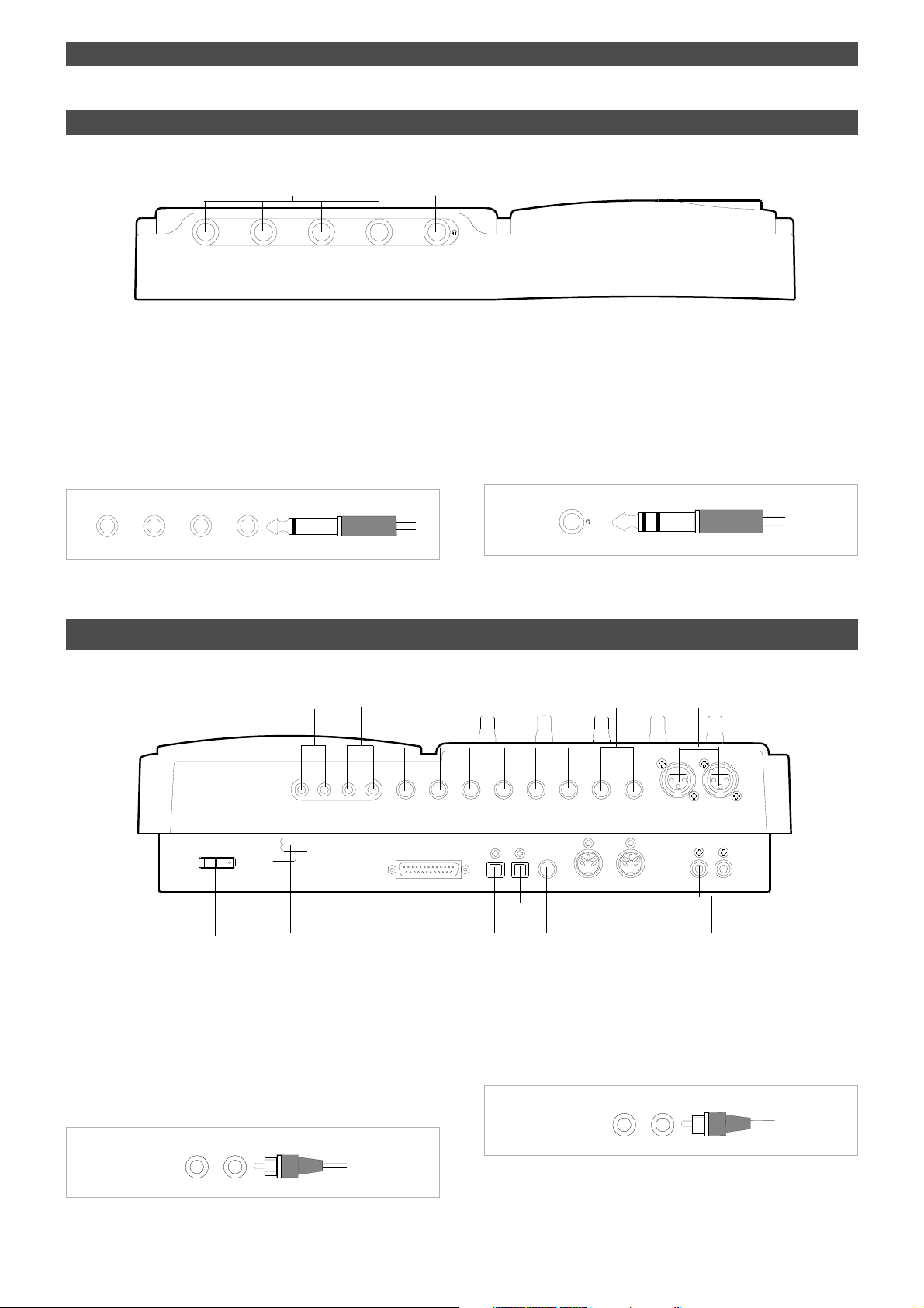
Names and Functions
Front Panel (Input/Output Section)
1.Input jacks [1, 2, 3, 4]
1
21
(Connector: phone)
3
2
4
Connect sound sources, such as musical instruments and
microphones, here.
Connect a microphone to input jacks 3 and 4, which are
equipped with TRIM switches that allow you to switch
according to the connected microphone output level. Input
channels 3 and 4 also support balanced XLR connectors on
the rear panel.
21
3
4
Rear Panel (Input/Output Section)
The phone jacks for input channels 3 and 4 on the front
panel have priority. If you connect sound sources to these
jacks, the balanced XLR jacks for input channels 3 and 4 on
the rear panel will be disabled.
2.Headphone jack [PHONES]
(Connector: stereo TRS phone)
Connect headphones here. You can adjust the headphone
volume using the MASTER knob in the monitor section.
1
R MON OUT L
POWER
15
1. Monitor Out jacks [MON OUT L, R]
14
2
R ST OUT L
3
2 AUX SEND 1
13
(Connector: RCA pin)
SCSI
Connect monitoring speakers and amplifier or powered
speakers here. These jacks output signals selected by the
SELECTOR in the monitor section (L/R, L/R+MON, or MON).
Use the MASTER knob in the monitor section to adjust the
output level.
R MON OUT L
AUX RTN 2
R MONO/L
DATA
4
DATA
OUTIN
AUX RTN 1
R MONO/L
PUNCH
IN/OUT
56
INPUT 3
INPUT 4
4 INSERT 3
MIDI
MIDI
OUT
RECORDER IN
R
LIN
11
12
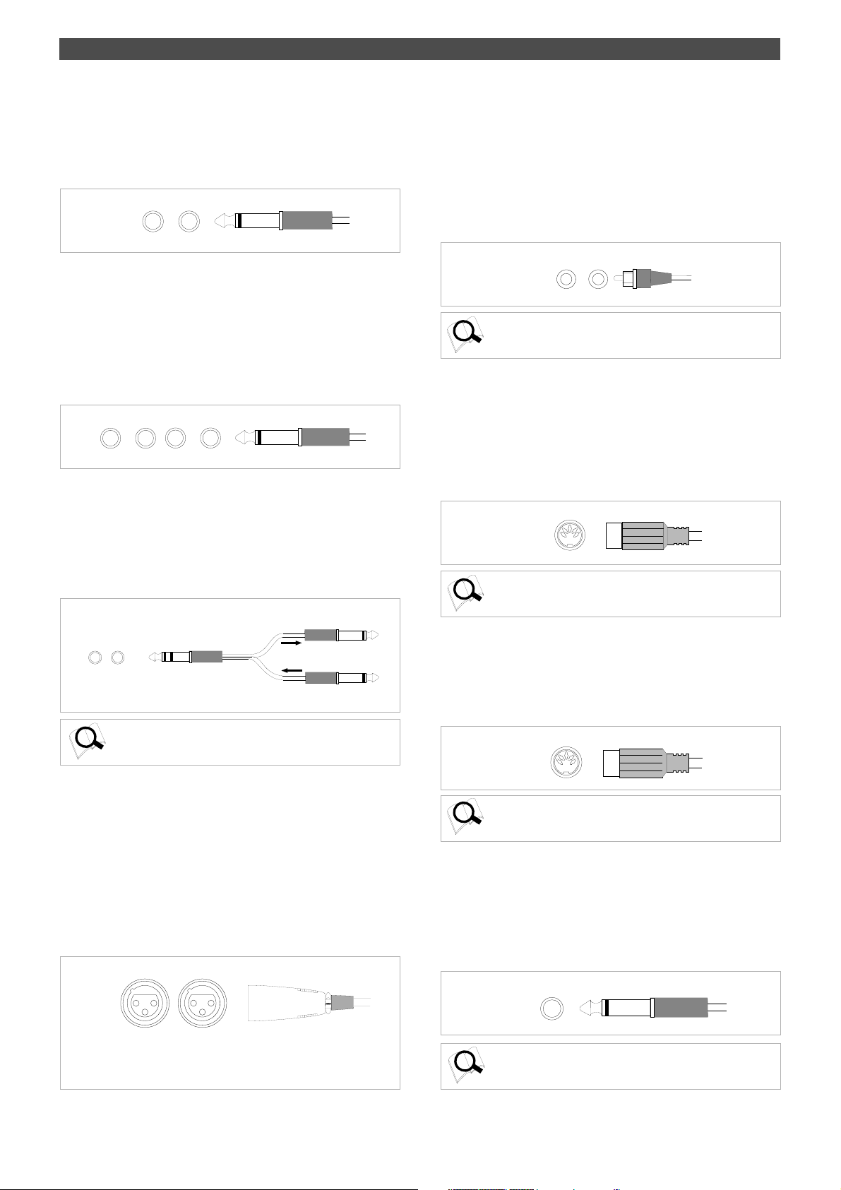
2. Stereo Out jacks [ST . OUT L, R]
These jacks output stereo bus L/R signals. Connect these
jacks to the input jacks of a master recorder. You can adjust
the output level using the master fader L/R.
R ST OUT L
78910
(Connector: RCA pin)
18
Page 19
Names and Functions
RECORDER IN
R
L
3. AUX Send jacks 1, 2 [AUX SEND 1, 2]
(Connector: phone)
Connect these jacks to the input of an effect unit.
The AUX SEND jacks send out signals selected and adjusted
by the AUX send knobs to the connected effect unit.
2 AUX SEND 1
4. AUX Return jacks 1, 2 [AUX RTN 1, 2]
(Connector: phone)
Connect these jacks to the output of an effect unit.
You can also use these jacks as auxiliary inputs.
If a connected effect unit has a mono output, connect the
output to the L/MONO jack of the FD-4. The right channel
will also receive the same signal. Adjust the level of processed
signals using AUX RTN knobs 1 and 2.
AUX RTN 1
MONO/L
R
R
AUX RTN 2
MONO/L
5. Insert jacks 3, 4 [INSERT 3, 4]
(Connector: stereo TRS phone)
Use these jacks when you wish to apply an effect to the
signal input at input jacks 3 and 4 (unbalanced inputs on
the front panel or balanced inputs on the rear panel).
In particular, use them when you wish to apply a
compressor/limiter.
7. Recorder in jacks L, R [RECORDER IN L, R]
(Connector: RCA pin)
These jacks are used to route analog signals input from an
external device directly to the recorder section. Using these
jacks enables you to use only the recorder section, bypassing
the mixer section.
Signals input from these jacks are recorded to the tracks
selected by the RECORD TRACK select keys.
Refer to page 55 for more information on using the
RECORDER IN jacks.
8. MIDI OUT jack [MIDI OUT]
Connect this jack to the MIDI OUT jack of an external MIDI
device.
This jack transmits MTC (MIDI timecode), MIDI clock & Song
Position Pointer, MMC (MIDI Machine Control) command,
response, and FEX (Fostex System Exclusive Message)
response.
MIDI
OUT
Refer to page 71 for more information on the example of using
the MIDI OUT jack.
(Connector: DIN 5-pin)
4 INSERT 3
Refer to page 41 for more information on examples of using
the INSERT jacks.
6. Balanced input connectors 3, 4 [INPUT 3, 4]
(Connector: balanced XLR)
Connect sound sources that have balanced outputs, such
as musical instruments and microphones.
Input channels 3 and 4 also support phone jacks on the
front panel.
The phone jacks for input channels 3 and 4 on the front
panel have priority. If you connect sound sources to these
jacks, the balanced XLR jacks for input channels 3 and 4 on
the rear panel will be disabled.
INPUT 3INPUT 4
Pin 1: GND
Pin 2: HOT
Pin 3: COLD
9. MIDI IN jack [MIDI IN]
(Connector: DIN 5-pin)
Connect this jack to the MIDI IN jack of an external MIDI
device. You can control the FD-4 remotely by inputting
MMC (MIDI Machine Control) command or FEX (Fostex
System Exclusive Message) here.
MIDI
IN
Refer to page 71 for more information on using the MIDI IN
jack.
10. Punch in/out jack [PUNCH IN/OUT]
(Connector: phone)
Using an optional foot switch connected to this jack enables
you to perform the Manual Punch In/Out operation
(including rehearsal) using your foot. Connect an optional
Fostex foot switch, Model 8051.
PUNCH
IN/OUT
Refer to page 46 for more information on using the PUNCH
IN/OUT jack.
19
Page 20
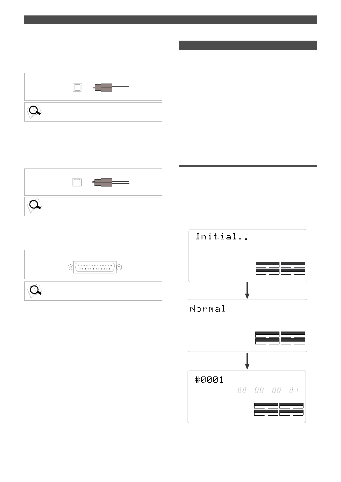
Names and Functions
1 1. Data output jack [DA TA OUT]
(Connector: OPTICAL)
Connect this jack to the OPTICAL digital input of an external
digital device to save song data to a DAT or to record digitally
to a digital device (MD, DAT, CD-R, etc.).
DATA
OUT
Refer to pages 52 and 76 for more information on using the
DATA OUT jack.
12. Data input jack [DA T A IN]
(Connector: OPTICAL)
Connect this jack to the OPTICAL digital output of an external
digital device to load song data from a DAT or to record
data digitally from a digital device (MD, DAT, CD-R, etc.) to
the FD-4.
DATA
IN
Refer to pages 52 and 76 for more information on using the
DATA IN jack.
13. SCSI connector [SCSI]
(Connector: D-SUB 25-pin)
Connect an external SCSI drive as the recording media for
the FD-4.
Display Section
The FD-4 uses a liquid crystal display which integrates a 9digit/35-dot message section, 7-segment display section,
and level meters.
The level meters indicate the output level of tracks 1-4 and
stereo out L/R.
The time display shows various temporal information in
different units, such as ABS time (absolute time), MTC (MIDI
timecode), BAR/BEAT/CLK (bar/beat/clock), and makes it
easy to check the recorder’s current time.
The message display shows various messages required to
operate the FD-4, and offers interactive operation.
This section describes display functions along with examples.
Display when the power is turned on
When you turn the power on to the FD-4 and the connected
external SCSI drive (with a formatted removable disk
inserted), the display shows the [Initial...] message, then
Recording mode (Normal, Master 1 or Master 2), and finally
the Time Base of the last Program that was used before you
turned the power off.
The following example shows that the FD-4 started with the
ABS Time Base used in Program 1.
44.1kHz
SCSI
Refer to page 5 for more information on connecting an external
SCSI drive.
14. Power cable
Connect the power cable to an AC outlet.
15. Power switch [POWER]
This switch turns power on and off to the FD-4.
ABS
SETUP
DRIVE
44.1kHz
DRIVE
44.1kHz
DRIVE
SYNC OUT
CLK
AUTO A.PUNCH
SURE?
SYNC OUT
AUTO A.PUNCH
SMF
SYNC OUT
CLK
AUTO A.PUNCH
SCSI
SCSI
PGM
SCSI
20
Page 21
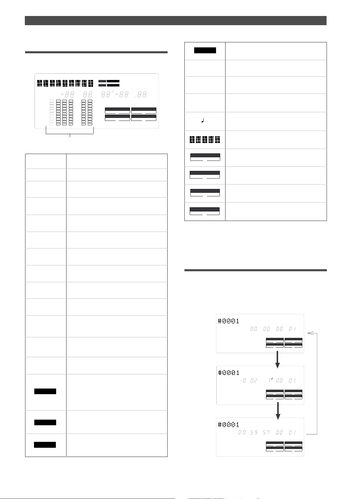
Names and Functions
SYNC OUT
AUTO
A.PUNCH
Preset display
The display below shows all preset items for explanation
purposes.
DIGITAL
REMAIN ABS
LOC MTC IN
The level meter shows the recorder output level and the
recording level for tracks 1~4 and stereo bus L, R.
ABS
MTC
REMAIN
SETUP
COMPLETED !
SURE ?
MTC OFFSET
PGM
TEMPO
VARI PITCH
44.1kHz
MTC IN
MTC
SLAVE
MIDI
BAR
SMH
VARI PITCH TEMPO PGM
SURE
SYNC OUT
Lights up when ABS is selected as Time Base.
Lights up when MTC is selected as Time Base.
Lights up to indicate available recording time and
space on the disk.
Lights up when the FD-4 enters SETUP mode.
Lights up when an edit operation (copy, move,
paste, or erase) is completed.
Lights up to confirm or cancel the operation when
you are making settings or edits.
Lights up when the MTC Offset menu is selected
in SETUP mode.
Lights up to indicate the current Program number.
Lights up when the tempo setting menu is selected
in SETUP mode.
Lights up when Vari Pitch mode is turned on.
Indicates a sampling rate of the corresponding
Recording mode. It does not light up when the disk
is formatted in Normal mode.
Lights up to indicate that MTC is input from an
external MIDI device to the FD-4.
44.1kHz
SETUP MTC OFFSET
CLK
DF
?
COMPLETED
DRIVE
AUTO A.PUNCH
MB
SF
!
MTC
%
MB
H, M, S, F , SF
BAR,
, CLK
Lights up when the FD-4 receives MTC (MIDI Time
Code) from an external device.
Lights up when the FD-4 enters Vari Pitch data edit
mode.
Indicates available disk space on the disk in
megabytes when the REMAIN indicator appears.
Lights up to indicate a time value when ABS or MTC
is used as Time Base.
Lights up to indicate a bar/beat/clock value when
BAR/BEAT/CLK is selected as T ime Base.
Indicates a Program title, edit parameters, and
SETUP mode parameters.
Indicates the “SYNC OUT settings” in SETUP
mode.
Indicates the AUTO PLAY/AUTO RTN mode
settings.
DRIVE
Indicates the current drive. Usually, [SCSI] lights
up.(*)
Indicates the AUTO PUNCH mode settings.
(*) When the FD-4 has the optional 2.5 inch internal IDE hard disk installed, and an
external SCSI drive is not connected, [IDE] will be lit. However, even though an
internal hard disk has been installed, if the external SCSI drive is connected, the SCSI
drive will have priority and [SCSI] will be lit.
Display examples for Time Base selected via the
TIME BASE SEL key
You can use the TIME BASE SEL key to select ABS, BAR/
BEAT/CLK, or MTC as Time Base. The following examples
show the displays when you select a Time Base at the
beginning of the disk of Program 1.
Time Base is ABS.
44.1kHz
ABS
SM
F
PGM
SYNC OUT
CLK SCSI
AUTO A.PUNCH
DRIVE
LOC
DIGITAL
SLAVE
MIDI
Lights up when the FD-4 enters locate point (edit
point) edit mode.
Lights up when the digital input track settings are
made in SETUP mode and the FD-4 is receiving
digital signals correctly. However , if the FD-4 is not
receiving digital signals correctly, or if there is a
connection problem, this indicator flashes.
Flashes when Slave mode in SETUP mode is turned
on. When a signal is locked, the flashing indicator
lights up steadily.
Lights up when the FD-4 is receiving effective MIDI
messages (MMC or FEX) from an external device.
Time Base is BAR/BEAT/CLK.
Time Base is MTC.
MTC
H
BAR
SYNC OUT
CLK SCSI
AUTO A.PUNCH
M
S
SYNC OUT
CLK SCSI
AUTO A.PUNCH
44.1kHz
CLK
44.1kHz
F
PGM
DRIVE
PGM
DRIVE
21
Page 22
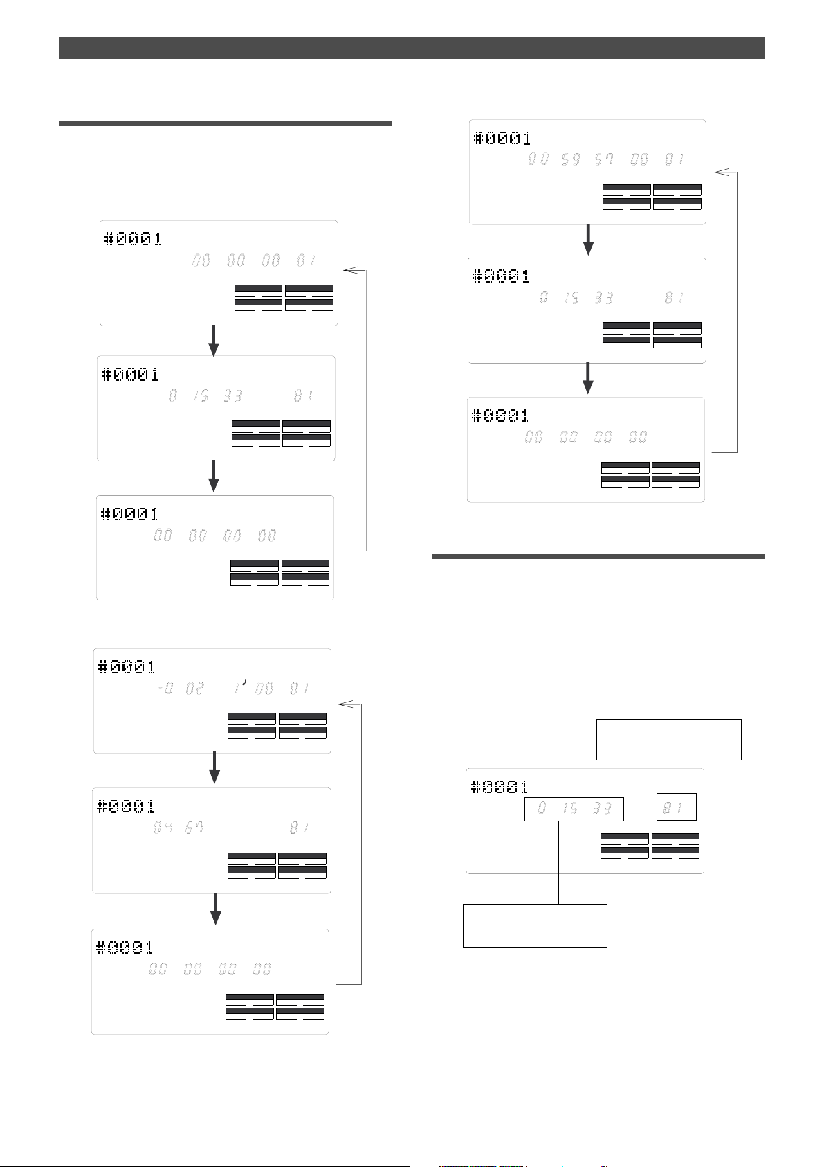
Names and Functions
Selecting Time Base using the DISP SEL key
When you press the DISP SEL key after you select a Time
Base using the TIME BASE SEL key, the display changes as
follows:
Time Base is ABS.
44.1kHz
REMAIN
ABS
H
SM
SYNC OUT
CLK SCSI
AUTO A.PUNCH
M
S
SYNC OUT
CLK SCSI
AUTO A.PUNCH
F
44.1kHz
44.1kHz
PGM
DRIVE
MB
DRIVE
Time Base is MTC.
MTC
REMAIN
MTC IN
M
H
H
H
S
SYNC OUT
CLK SCSI
AUTO A.PUNCH
M
S
SYNC OUT
CLK SCSI
AUTO A.PUNCH
S
MF
SYNC OUT
CLK SCSI
AUTO A.PUNCH
44.1kHz
F
44.1kHz
44.1kHz
PGM
DRIVE
MB
DRIVE
DRIVE
H
MTC IN
MF
Time Base is BAR/BEA T/CLK.
BAR
REMAIN
BAR
S
SYNC OUT
CLK SCSI
AUTO A.PUNCH
DRIVE
44.1kHz
CLK
PGM
SYNC OUT
CLK SCSI
AUTO A.PUNCH
DRIVE
44.1kHz
SYNC OUT
CLK SCSI
AUTO A.PUNCH
DRIVE
44.1kHz
The REMAIN display
The REMAIN display always indicates the figure converted to
mono track.
In other words, the remaining disk capacity for one track in
which a recording can be made and the remaining time are
displayed. The figure displayed here applies to all of the real
tracks and additional tracks.
For details on the REMAIN display, please refer to “FD-4
recording type and the REMAIN indicator” in “Before starting”
on page 25.
Disk recordable remaining
capacity is displayed.
44.1kHz
REMAIN
MB
M
H
S
SYNC OUT
CLK SCSI
AUTO A.PUNCH
Disk recordable remaining
time is displayed.
MB
DRIVE
22
MTC IN
H
S
MF
SYNC OUT
CLK SCSI
AUTO A.PUNCH
DRIVE
Page 23
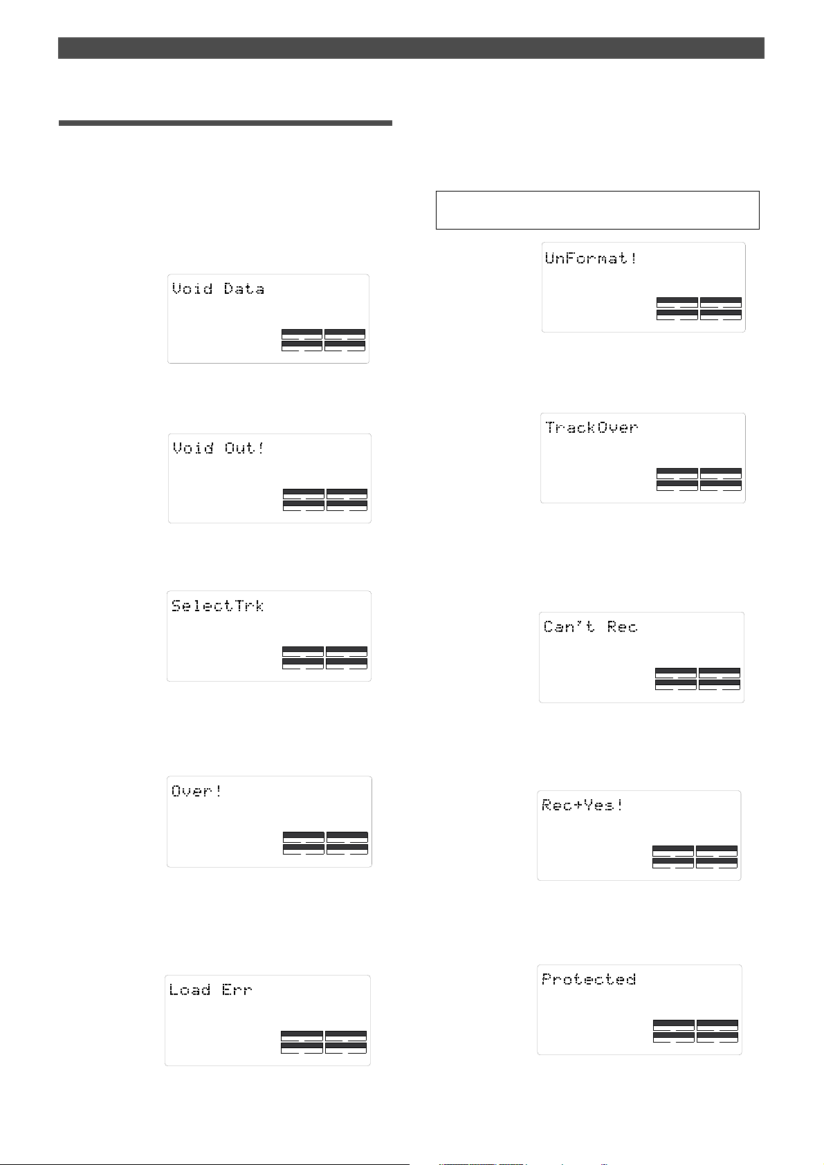
Names and Functions
Warning messages
The following warnings are shown operating mistakes are
made, an unsuitable editing point (= locate point) is input,
or when errors occur. If any of these warnings appear,
refer to information detailed below.
<Void Data> message
This means registered data necessary for the selected operation
is incorrect.
Action to take:
Re-register the correct data.
SYNC OUT
CLK
AUTO A.PUNCH
<Void Out> message
This means the registered in/out point is wrong.
Action to take:
Re-register the correct data.
SYNC OUT
CLK
AUTO A.PUNCH
<Track unselected> message
This means a track has not been specified.
Action to take:
Select any one track with the RECORD TRACK select key.
DRIVE
DRIVE
SCSI
SCSI
<Unformat !> message
An unformatted or crashed SCSI disk.
After a few seconds of this display, the FD-4 automatically enters
the SETUP mode [Format ?] menu.
Action to take:
Press the EXECUTE/YES key while pressing the RECORD button.
<Note>
Any sound data recorded up to this point on the disk will be lost.
SYNC OUT
AUTO A.PUNCH
DRIVE
<Track Over> message
This means the number of recording tracks has been exceeded.
Action to take:
Simultaneous recording is possible on only two tracks. Setup
the recording track again.
SYNC OUT
CLK
AUTO A.PUNCH
DRIVE
SCSI
<Can’t Rec> message
This means the specified additional track cannot be recorded.
This is displayed when recording is attempted on the additional
track by using the [Mastering mode 2] disk.
Action to take:
If recording is to be make on the additional track, format in the
[Normal mode] or [Mastering mode 1].
SYNC OUT
CLK
AUTO A.PUNCH
DRIVE
SCSI
<Over> message
This means that disk space necessary for recording and editing
is insufficient.
Action to take:
Before proceeding to the next operation, temporarily data in
order to source empty space necessary for the next operation.
SYNC OUT
CLK
AUTO A.PUNCH
DRIVE
SCSI
<Load Err > message
This means that loading is impossible because there is an error
in data applied to the DATA IN connector from the external
DAT.
Action to take:
Check the external DAT connected to the DATA IN connector
and be sure there is no problem with the DAT tape. Then, try
loading again.
SYNC OUT
CLK
AUTO A.PUNCH
DRIVE
SCSI
SYNC OUT
CLK
AUTO A.PUNCH
DRIVE
SCSI
<Rec + Yes !> message
This means press the EXECUTE/YES key while pressing the
RECORD button (This is displayed when formatting).
Action to take:
Press the EXECUTE/YES key while pressing the RECORD button.
SETUP
?
SURE
SYNC OUT
CLK
AUTO A.PUNCH
DRIVE
SCSI
<Protected> message
This means the disk inserted in the drive cannot be used because
it is write-protected. The disk will be ejected automatically.
Action to take:
Release the write-protect and re-insert it.
SYNC OUT
CLK
AUTO A.PUNCH
DRIVE
SCSI
23
Page 24
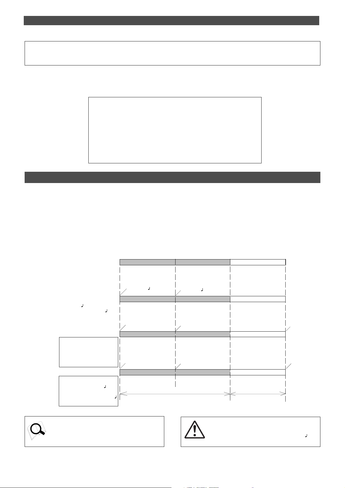
Before Starting
Before Starting
This chapter describes some basic items that you need to know before you start operating the FD-4.
All users, including those who are familiar with using tape-based multitrackers and those who are new to multitrackers,
should read this chapter thoroughly to understand the functions of the FD-4.
1. Time Base
2. Recording method and REMAIN display
3. Managing songs by Program Change function
4. Real tracks and Additional tracks
5. Input monitoring and playback monitoring
6. P AN knobs and stereo bus
Time Base
The word “Time Base” appears frequently in this manual. The concept of Time Base is similar to a “tape counter” on a
conventional tape-based multitracker in that it indicates the precise position of the recorder transport section (the current
position).
The FD-4 offers three types of Time Base: ABS (Absolute type), MTC (MIDI time code), and BAR/BEAT/CLK (bar/beat/clock).
ABS indicates an absolute time on the disk. MTC indicates a relative time that is obtained by adding a certain value (MTC
offset value) to the ABS value. BAR/BEAT/CLK indicates the position in a song created in the internal Tempo Map according
to MIDI clock and Song Position Pointer. The following diagrams depict the relationship among these three types of the Time
Base.
ABS 0
00M, 00S, 00F
00M, 08S, 00F REC END
DISK END
23H, 59M, 59S
ABS
-002BAR, 1 , 00CLK
001BAR, 1 , 00CLK
BAR/BEAT/CLK
BAR =001BAR, 0404
TEMPO=001BAR, 1 , 60
01H, 00M, 00S, 00F
01H, 00M, 08S, 00F
00H, 59M, 59S
MTC
MTC OFFSET=01H, 00M, 00S, 00F
MTC OFFSET MODE=ABS
(This shall be assumed to be the
MTC OFFSET time set for the ABS
00M, 00S and 00F positions.)
00H, 59M, 52S, 00F
01H, 00M, 00S, 00F
00H, 59M, 51S
MTC
MTC OFFSET=01H, 00M, 00S, 00F
MTC OFFSET MODE=BAR
(This shall be assumed to be the MTC
OFFSET time set for the 00 BAR, 1
and 00 CLK positions.)
Recorded area
Non recorded area
24
You can switch between these three types of Time Base to
suit your purpose. (Refer to the explanation in “Display Section” on page 21 for more information on switching Time
Base.)
<Note>
When BAR/BEAT/CLK is selected as T ime Base, the position for ABS 0 (top of the disk) is always “- 2 BAR, 1 , 00
CLK” and you cannot modify this value.
Page 25
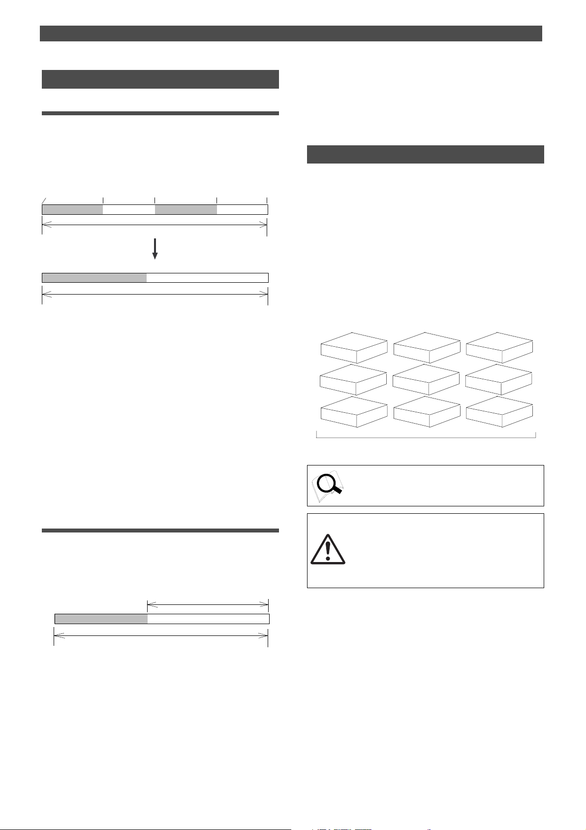
Before Starting
Recording method and REMAIN indicator
Recording method
The FD-4 uses a SCSI removable disk (such as an MO disk or
Zip disk) instead of a cassette tape. You can start recording
sound sources from any point on a formatted disk as long
as the point is within the range of 24 hours in ABS time.
(Refer to the following diagram.)
ABS 0
recorded area (3 min.) unrecorded area
03M 00S 00F
You can record at any point within 24 hours in ABS Time.
10M 00S 00F 12M 00S 00F
recorded area (2 min.)
REC END
unrecorded area
The area actually used on the disk
recorded area (5 min.) unrecorded area
Recordable disk area.
For example, if you record three minutes of data starting
from ABS 0 (top of the disk) as shown in the diagram, then
record two minutes starting at the 10-minute point in ABS
time, the recording end point is 12 minutes in ABS time.
However, this does not mean that the entire recording duration is 12 minutes. The disk space actually used for recording is five minutes (3 minutes + 2 minutes). That is,
the area between three minutes and ten minutes in terms
of ABS time is still unrecorded.
When you try to play or fast forward this unrecorded area,
the time counter on the display will count, but the FD-4 will
not access the disk. However, MTC will be output when you
try to play this area.
On the FD-4, the top of the disk is called “ABS 0” and the
recording end point is called “REC END.”
DISK END
23H, 59M, 59S
If you wish to know how much you can record on four
tracks, you need to divide the current REMAIN value by
four.
Managing songs by Program Change function
The FD-4 features Program Select function, which enables
you to set up to 99 Programs on the disk.
When you format a disk, one Program will be automatically
created on the disk. You may create more Programs, if necessary. You may also delete unnecessary Programs.
The FD-4 also features Program Change function that enables you to select one of the Programs set on the disk.
Programs on the disk are something like independent containers. You can record, play, and edit each container without affecting other containers.
You can also name Programs, which is useful for managing
songs.
Program 1
Program 4 Program 5 Program 6
Program 7
You can set up to 99 Programs (independent containers).
Refer to page 36 for more information on the Program Select
function.
Program 2 Program 3
Program 8
Program 9
REMAIN indicator
The REMAIN indicator displays available recording time expressed in time value or bar/beat/clock value, depending
on the currently selected Time Base. It also indicates the
available disk space.
recorded area (5 min.)
recordable disk area
Right after you format the disk, the REMAIN indicator will
show the maximum recordable time and space on the disk.
The values will decrease as the actual recorded area expands. The REMAIN value is calculated by deducting the
time and space of all data on the Real tracks and Additional
tracks from the original available recording time and space
in mono-track base. That is, the value indicates available
recording time and space if you record on one mono track.
The REMAIN indicator displays the
amount of unrecorded area.
unrecorded area
<Note>
T otal available recording time is always the maximum available recording time on the disk, regardless of the number of
Programs you set on the disk. That is, if you use up the
maximum recording time for one Program, you will not be
able to record any data in other Programs.
25
Page 26
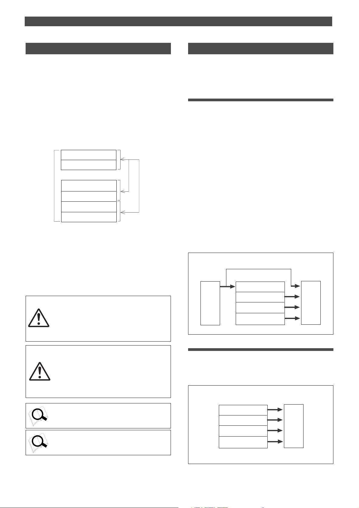
Before Starting
Real track and Additional track
The FD-4 features four Real tracks (1–4) and two Additional
tracks (L and R), for a total of six tracks.
Real tracks are used to record sound sources in real-time.
Additional tracks are used to temporarily store the sound
recorded in the Real tracks.
This is useful since you can move data from Real tracks to
Additional tracks to obtain empty tracks for recording.
The Track Exchange function of the FD-4 handles this operation. This function allows you to swap data freely between six mono tracks. You can also swap Real tracks 1–2
or 3–4 with Additional tracks L and R.
Track R
Track L
You can swap
data between
six mono tracks.
Additional tracks
Track 4
Track 3
Track 2
Track 1
Real tracks
If the disk is formatted in Normal mode or Matering mode
1, you can record to Additional tracks in real-time.
This feature allows you to perform ping-pong recording
from Real tracks 1–4 to Additional tracks L and R.
You cannot use this feature with a disk in Mastering mode
2, although you can still use the Track Exchange function.
<Note>
You cannot play back data on Additional tracks in all
recording modes. If you wish to play data on an Additional track, first use the Track Exchange function to
move the data to a Real track.
<Note>
Data on the Additional tracks also affects the REMAIN value. If Real tracks contain no data, but Additional tracks contain data, the amount of the data
(time and space) will be reflected in the REMAIN
value.
You can also
swap Real tracks
1–2 or 3–4 with
Additional tracks
L and R.
Input monitoring and playback monitoring
There are two methods for monitoring track sound (only
on the Real tracks): input monitoring and playback monitoring. They are defined as follows:
Input monitoring
Input monitoring means to monitor via track output the
recording signal sent to the Real tracks of the recorder.
That is, you are monitoring a post-recorder signal, not a
pre-recorder signal. The FD-4 enters input monitoring status when you perform one of the following operations.
• When you set a track to recording mode
To set a track to recording mode, press the RECORD TRACK
select key to set the track READY, then press the PLAY button
while holding down the RECORD button.
When recording starts on the READY track, the FD-4 auto
matically enters input monitoring status.
• When you set a track to recording stand-by mode
To set a track to recording stand-by mode, press the RECORD
TRACK select key to set the track READY, then press only the
RECORD button. (Pressing the RECORD button again will cause
the FD-4 to enter playback monitoring mode.)
Under this condition, only the READY track enters input moni
toring mode, on stand-by for recording.
Track 4: INPUT monitor , Tracks 1~3: REPRO monitor
Track 4
INPUT
Track 3
Track 2
Track 1
Monitor
section
Playback monitoring
“Playback monitoring” means to monitor the playback
sound of the tracks (only Real tracks). That is, you are monitoring the playback sound on the track, not the sound being recorded to the track.
All tracks: REPRO monitor
26
Refer to page 60 for more information on the Track Exchange
function.
Refer to page 51 for more information on the Ping-pong recording to additional track.
Track 4
Track 3
Track 2
Track 1
Monitor
section
Page 27
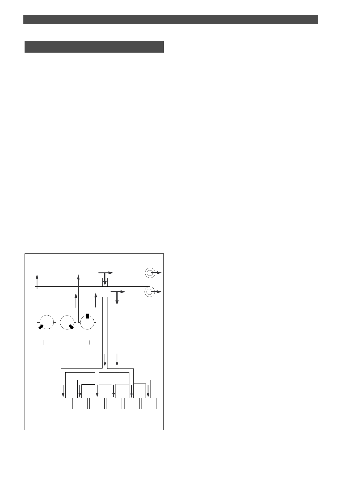
P AN knobs and stereo bus
The FD-4 features a four-channel mixer function that enables you to mix four sound sources into a stereo mix.
Since the mixer functions and signal flow are not visible,
the following diagram will help you understand them.
The diagram shows the flow of signals from the inputs
through the mixer section to the recorder.
The thick line in the diagram is called the “stereo bus”,
which collects the channel signals that are panned and processed by the EQ. The signals are adjusted for the final
level by the master faders L/R, then routed to the STEREO
OUT L/R jacks. The same signals are routed to the recorder
(external SCSI disk) and recorded in the specified tracks.
In this case, the PAN knobs function like a turn signal to
stereo buses L and R. As shown in the diagram, rotating the
PAN knob toward L will cause signals to be sent to stereo
bus L. Rotating the PAN knob toward R will cause signals to
be sent to the stereo bus R. Stereo bus L signals are then
routed to Real tracks 1 and 3 and Additional track L.
Stereo bus R signals are routed to Real tracks 2 and 4 and
Additional track R. You can select a recording track using
the RECORD TRACK select keys. (You can record to Additional tracks in real-time only on the disk in Mastering mode
1 or Normal mode.)
For example, to record all sound sources input to channels
1–4, turn all channel PAN knobs completely to L, and press
the RECORD RACK select key 1/L to set the track READY.
Before Starting
STEREO BUS L
STEREO BUS R
LRLRLR
PAN knob
1/L
2/R 3/L 4/R
REC SEL switch
ST OUT L, R
LR
27
Page 28
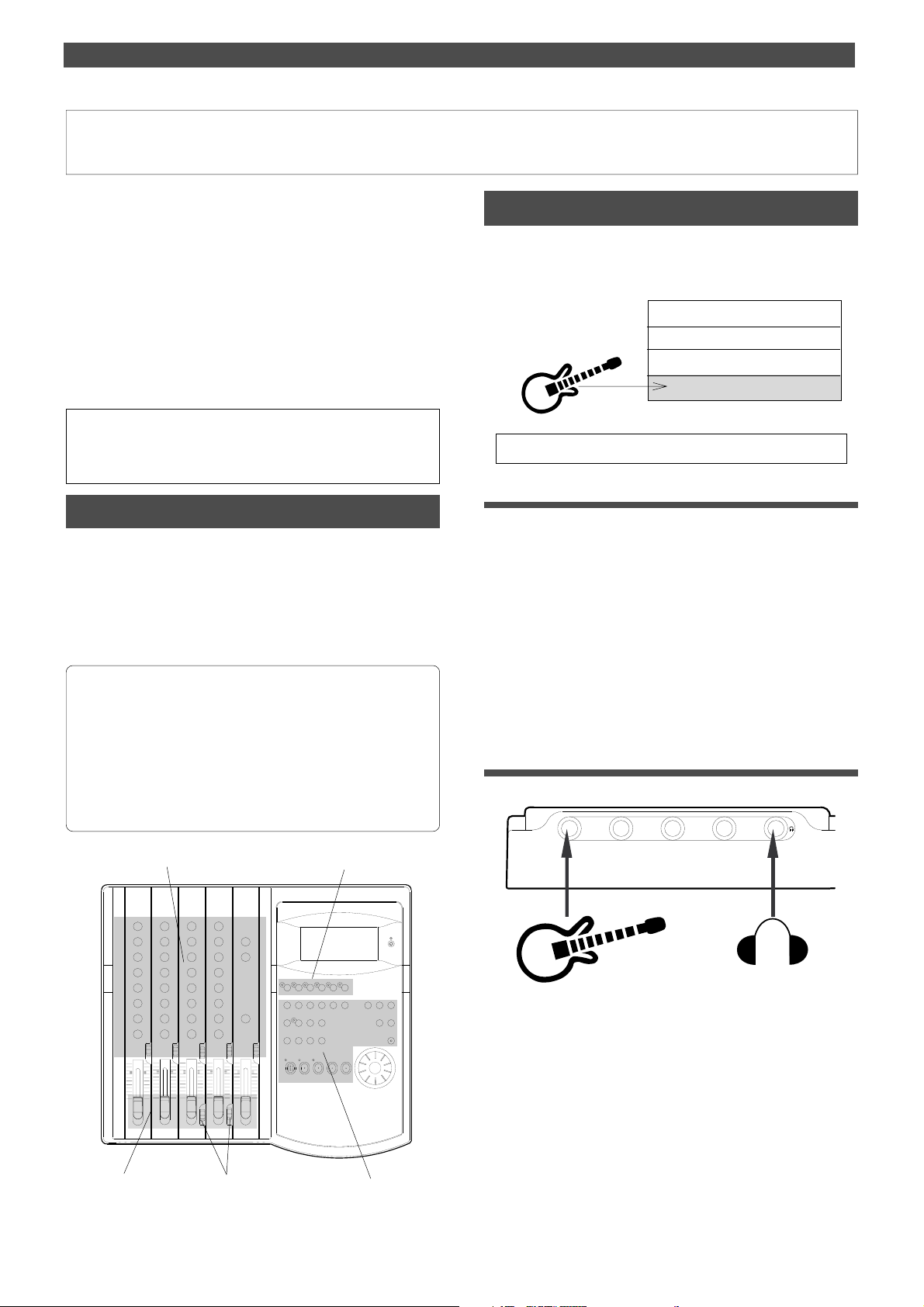
Basic Application (Basic Recording and Playback)
Basic Recording and Playback
This chapter explains how to perform basic recording and
playback so that you can get used to operating the FD-4.
This chapter will be helpful not only for those who are new
to a multitracking, but also to those who are used to handling a tape-based multitracker to master the basic operation of the FD-4.
After you master this basic chapter, proceed to the next
“advanced” chapter to try multitrack recording using advanced techniques.
The explanations here assume that a SCSI drive is connected
as described in the “Recording Preparation” chapter and
the disk is formatted in “Normal” recording mode.
<Note>
You can record up to two tracks simultaneously. If you try to set more
than two tracks to READY mode, [Track Over] appears on the display
and recording mode will be canceled.
FD-4 initial settings
Before you start operating the FD-4, or when you wish to
proceed to the next step, you need to reset the knobs and
switches on the FD-4. This is called “initializing the FD-4” in
this document. Set the knob and switch settings to the following positions. Always remember to “initialize the FD-4”
before you proceed to the next step.
Recording one sound source to one track
To get used to basic recording, record one sound source to
one Real track. We will use electric guitar as the sound source
in this example.
Real track 4
Real track 3
Real track 2
Real track 1
* Initialize the FD-4 before recording.
Setting the disk
1.Turn on the power to the FD-4 and the SCSI drive, and insert
the disk.
The FD-4 displays [Normal] (recording mode), then
displays the start of ABS time (ABS 00M 00S 00F).
2.Press the DISP SEL key to display the REMAIN indicator.
The REMAIN indicator shows the available recording
duration and free disk space for mono track recording.
<Initial settings>
1. Lower the input channel faders and master faders L/R.
2. Set the LEVEL switch for channels 3 and 4 to H (–10dB).
3. Set the knobs and switches to the center position or “0” position.
4. T urn all the RECORD RACK select keys to OFF (SAFE).
5. Set all control keys to off (LEDs will turn off).
Point 1
Point 3
EQ
EQ
Point 2
Point 4
Point 5
3.After you check the REMAIN time, press the DISP SEL key
to display the ABS time.
Connecting the guitar and the monitoring headphones
21
3
1.Connect the guitar to input jack 1, and connect the
monitoring headphones to the PHONES jack.
You can connect the guitar to any input jack.
If you wish to connect a sound source that requires the
adjustment of the input level, such as a microphone,
connect it to input jack 3 or 4. The input jacks support
either the mic level or line level, and have LEVEL switches
that allow for input level adjustment.
You can also use the balanced inputs (INPUTs 3 and 4) on
the rear panel to connect a balanced output from the
sound source (XLR connector).
4
28
Page 29
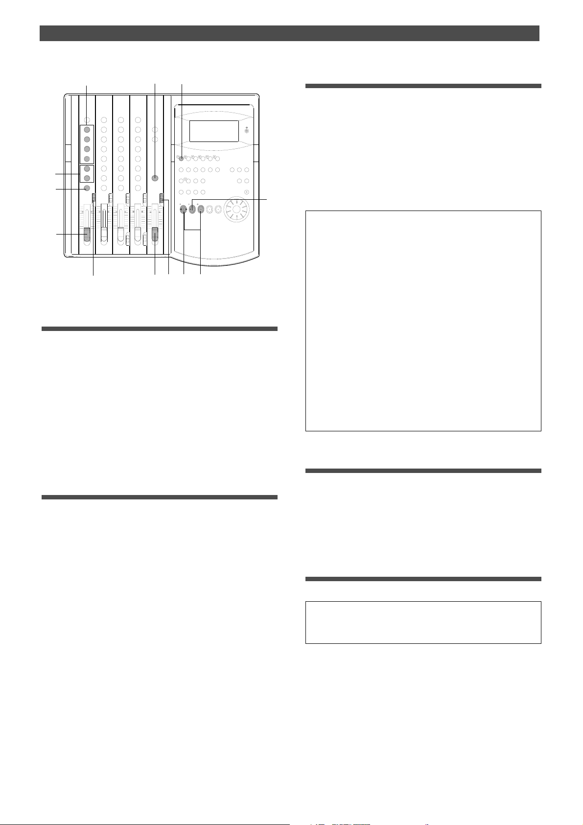
Basic Application (Basic Recording and Playback)
3
9
EQ
EQ
8
8
2
7
1
4
6
10
5
Setting the switch and knob
1.Set the channel 1 INPUT SEL switch to [INPUT].
The electric guitar signal is routed to the input channel 1
fader. If you connect the instrument to another input
jack, set the INPUT SEL switch of the corresponding
channel to [INPUT].
11
Monitoring the recording signal
8.Turn the MON knob in the MON mix section of channel 1
toward [TRK] and turn the MASTER knob in the monitor
section to adjust the monitoring level
Use the MON PAN knob in the MON mix section to adjust
the stereo image of the monitoring sound.
9.Adjust the equalizer for channel 1 if necessary.
If equalizing changes the level and the [OL] section of the
meter lights up, lower the level using the input channel 1
fader.
<Using the SELECTOR switch while monitoring>
* You can select the type of monitoring sound using the SELECTOR in the monitor section. Set the SELECTOR to [MON] to monitor the recording sound, and turn the MON knob in the MON mix
section for the channel that corresponds to the real track toward
[TRK]. Since we are now monitoring the track 1 recorder output,
use the MON mix section of channel 1. At this time, by turning the
MON knob toward [INPUT], you can monitor the pre-fader signal
routed from the input jack (the signal that is unaffected by the input
fader and equalizer).
* If you set the SELECTOR to [L/R], you can monitor the signal
routed to the recorder (the signal that is going to be recorded). Since
the level of the monitoring sound changes with the input fader position, regardless of the MON mix section setting, you need to use the
MASTER knob in the monitor section to adjust the monitoring level.
2.Turn the channel 1 PAN knob to [L] all the way .
The electric guitar signal is routed to the stereo bus L.
3.Press the RECORD RACK select key [1/L] so that the [1/L]
LED will flash.
Track 1 becomes READY mode.
Adjusting the recording level
4.Raise the master fader L/R to the [7–8] position.
5.Set the SELECTOR in the monitor section to [MON].
6.Press the RECORD button.
The RECORD LED flashes and track 1 enters input
monitoring mode.
In this mode, the electric guitar signal routed to track 1 is
output through the recorder track 1 output.
7.While playing the guitar, raise the input channel 1 fader to
[7–8], and adjust the recording level while checking the level
meter 1.
When you raise the input fader, the level meter L also
moves. This meter indicates the output level of the
stereo bus L.
Adjust the input fader so that the level meter will
occasionally reach the [0] point of the meter at
maximum volume. (Make sure that the meter at the [OL]
section will not light up.)
* If you set the SELECTOR to [L/R+MON], you can monitor both
signals with the [MON] and [L/R] settings.
Starting recording
10. Press the PLA Y button while holding down the RECORD
button.
The flashing RECORD LED and the LED of the READY track
remain lit, indicating that the track is now recording.
At this time, the recording Real track is in input
monitoring mode.
Stopping recording
1 1. T o stop recording, press the STOP button.
<Note>
After you finish recording, press the STOP button immediately. If
you keep recording silence, you will waste disk space.
Now you have recorded the guitar sound in Real track 1 via
the input jack 1. We can use the same method to record
other sound sources to other tracks.
The next table shows guideline settings for track 2–4 recording. You can connect any sound sources to any input
jacks.
29
Page 30
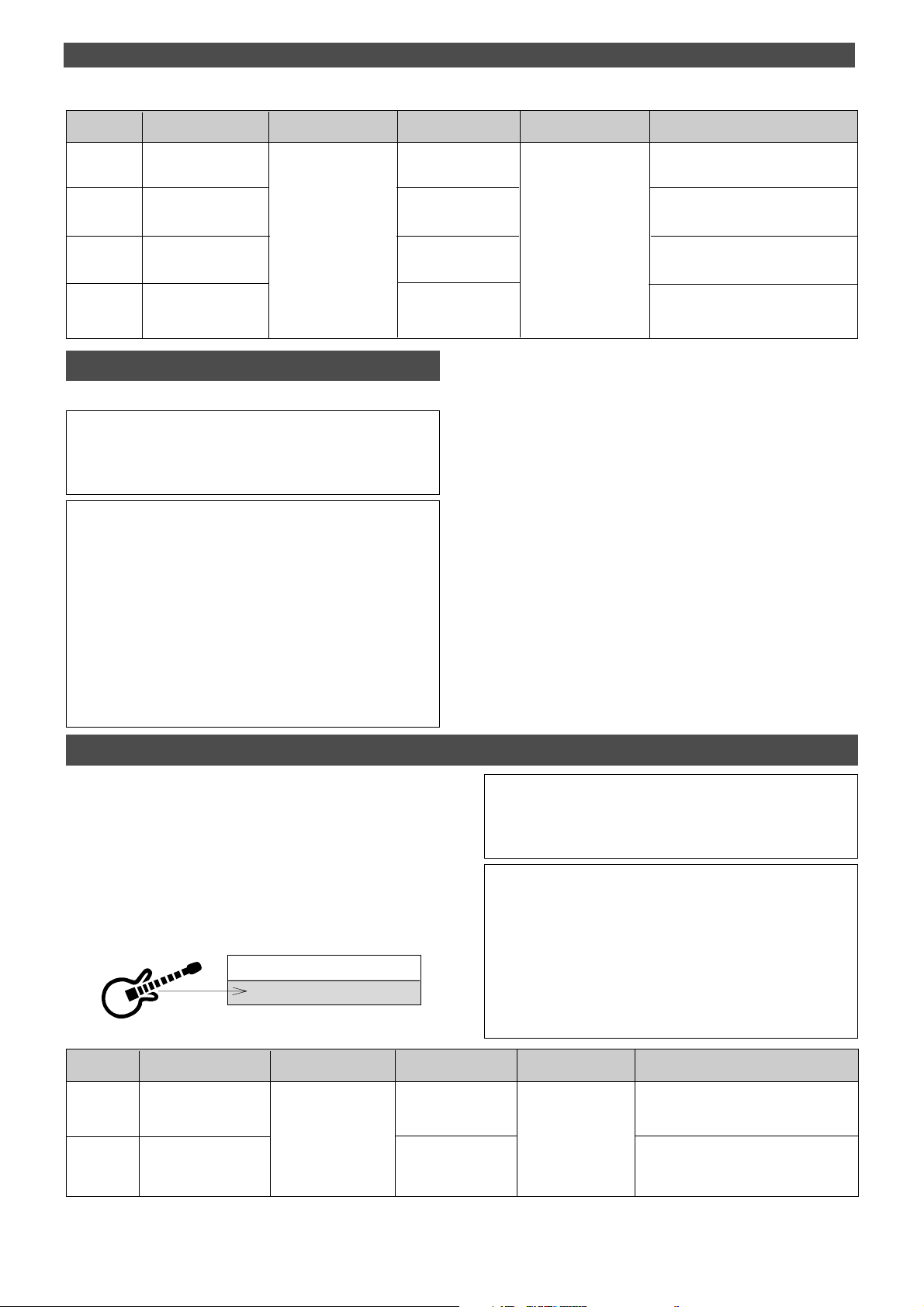
Basic Application (Basic Recording and Playback)
Recording
track
Track 1
Track 2
Track 3
Track 4
REC TRACK select key
for track READY
1/L is READY.
2/R is READY.
3/L is READY.
4/R is READY.
INPUT SEL switch
position
Set to INPUT
PAN knob adjustment
Turn all the way to R.
Turn all the way to R.
Undo/Redo recording
You can undo or redo a real-time recording.
• Press the UNDO/REDO key after recording is complete to restore
the conditions that existed prior to the recording.
• Press the UNDO/REDO key again to restore the conditions that
existed after the recording.
<Note>
The Undo/Redo is effective only in the stop mode of the FD-4.
Undo/Redo will not effective if the following is executed prior to carrying
out UNDO/REDO.
Turn all the way to L.
Turn all the way to L.
Monitor section’s
SELECTOR position
Set to MON
Adjusting the monitor sound of
the recording track
Use the channel 1 MON mix section to
adjust the monitoring sound for track 1.
Use the channel 2 MON mix section to
adjust the monitoring sound for track 2.
Use the channel 3 MON mix section to
adjust the monitoring sound for track 3.
Use the channel 4 MON mix section to
adjust the monitoring sound for track 4.
1. When a new recording made.
2. When a new editing is executed.
3. While in the Auto Punch On mode, when the AUTO PUNCH IN point
is passed in the PLAY (or RECORD) mode.
4. When the power is momentarily switched off.
5. When the program is changed.
6. When the disk is ejected.
Recording onto the additional track
On a disk formatted in the [Normal mode] or the [Mastering mode 1], real time recording is possible on the additional track L and R.
However, when real time recording onto the additional track,
unlike recording onto a real track, the additional track cannot be entered in the input monitor mode.
As shown in the chart below, the stereo bus L, R output
sound is directly monitored by switching the monitor section SELECTOR to [L/R].
Additional Track R
Additional Track L
<Note>
When recording is attempted on the additional track on a disk formatted in “Mastering mode 2,” [Can’t Rec] will be displayed and the
recording mode canceled.
* When recording on the additional track, if the monitor section SELECTOR is set to [L/R] as shown in the chart below, the stereo bus L,
R signal sound quality processed such as with an equalizer for example, can be monitored.
Also, if the SELECTOR is switched to [MON], and MON knob of the
channel to which the sound source is input is rotated to the [INPUT]
side, the pre-fader signal can be monitored. In other words, signals
which have not been affected by the INPUT fader and equalizer, can
be monitored.
Recording
track
Track L
Track R
30
REC TRACK select key
for track READY
L is READY.
R is READY .
INPUT SEL switch
position
Set to INPUT
PAN knob adjustment
Turn all the way to L.
Turn all the way to R.
Monitor section’s
SELECTOR position
Set to L/R
Adjusting the monitor sound of
the recording track
For the purpose of monitoring the stereo bus
L output, the monitor sound is adjusted only
with the monitor section MASTER knob.
For the purpose of monitoring the stereo bus
R output, the monitor sound is adjusted only
with the monitor section MASTER knob.
Page 31
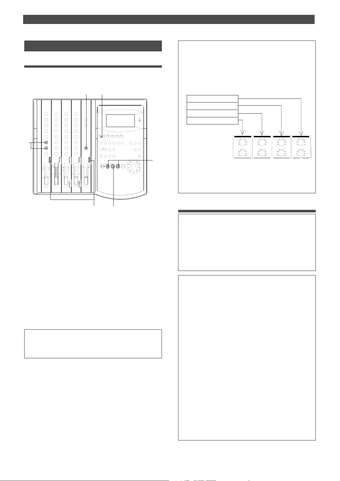
Basic Application (Basic Recording and Playback)
M
+
+
+
+
Checking the recording sound
Playing track 1
When you finish recording, play back the data if the recording is acceptable.
5
2
EQ
EQ
5
1
3 4
1.Press the REWIND button while holding down the STOP
button.
The FD-4 locates the beginning of the Program (ABS 0)
(LOCATE ABS 0).
2.Turn the RECORD TRACK select key off so that you will not
record data accidentally.
3.Leave the INPUT SEL switch and the SELECTOR in the
monitor section as they are.
4.Press the PLAY button to start playback.
5.Turn the channel 1 MON knob toward [TRK], and gradually
raise the MASTER knob in the monitor section. Use the MON
PAN knob to adjust the stereo image of the monitoring sound.
You can monitor the recorded sound on track 1.
<Note>
Do not raise the MASTER knob too high if you are monitoring through
headphones for a long period of time.
<Notes on playback>
When tracks 1–4 are played, the track signals are routed to the
MON mix section of the channels with the corresponding track numbers. That is, track 1 signal is routed to channel 1 MON mix section,
track 2 signal is routed to channel 2 MON mix section, etc.
T o monitor the track playback sound, use the corresponding channel’s
MON knob to adjust the level, and use the MON PAN knob to adjust
the stereo image.
Real track 4
Real track 3
Real track 2
Real track 1
MON MON MON MON
0
PAN
000
TRK1INPUT
TRK2INPUT
PAN
PAN
MON L MON RMON L MON R
MON L MON R
PAN
MON L MON R
TRK4INPUT
TRK3INPUT
Channel MON mix section
You can also route the track playback sound to the input faders. T o
do so, set the INPUT SEL switch to TRK.
Playback of the additional track sound
<Notes in playback on the Additional track>
Sound recorded on the additional track cannot be played back in
real time while it is located there. In order to playback the additional track’s sound, the recorded data must be temporarily exchanged with one of the real tracks. For explanations on mutually
replacing tracks, please refer to “Track Exchange Function” on page
60. The sound on the additional track exchanged to a real track
can be played back using the same procedures explained in the
left column.
<Undo/redo subsequent to exchange>
Even after temporarily exchanging onto a real track, “undo/redo”
can be executed for the purpose of checking the sound recorded
on the additional track, in the same way as at real track recording.
However, “undo/redo” subsequent to track exchange is permissible only once for each function. A second try will be ignored.
* If the UNDO/REDO key is pressed after checking the sound
transferred to the real track, it can be returned to the state
prior to recording onto the additional track.
* If the UNDO/REDO key is pressed subsequent to executing
UNDO, it can be returned to the state prior to exchange of the
additional track and the real track.
<Note>
The Undo/Redo is effective only in the stop mode of the FD-4, the same
as when recording onto a real track..
Undo/Redo will not effective if the following is executed prior to carrying
out UNDO/REDO.
1. When a new recording made.
2. When a new editing is executed.
3. While in the Auto Punch On mode, when the AUTO PUNCH IN point
is passed in the PLAY (or RECORD) mode.
4. When the power is momentarily switched off.
5. When the program is changed.
6. When the disk is ejected.
31
Page 32
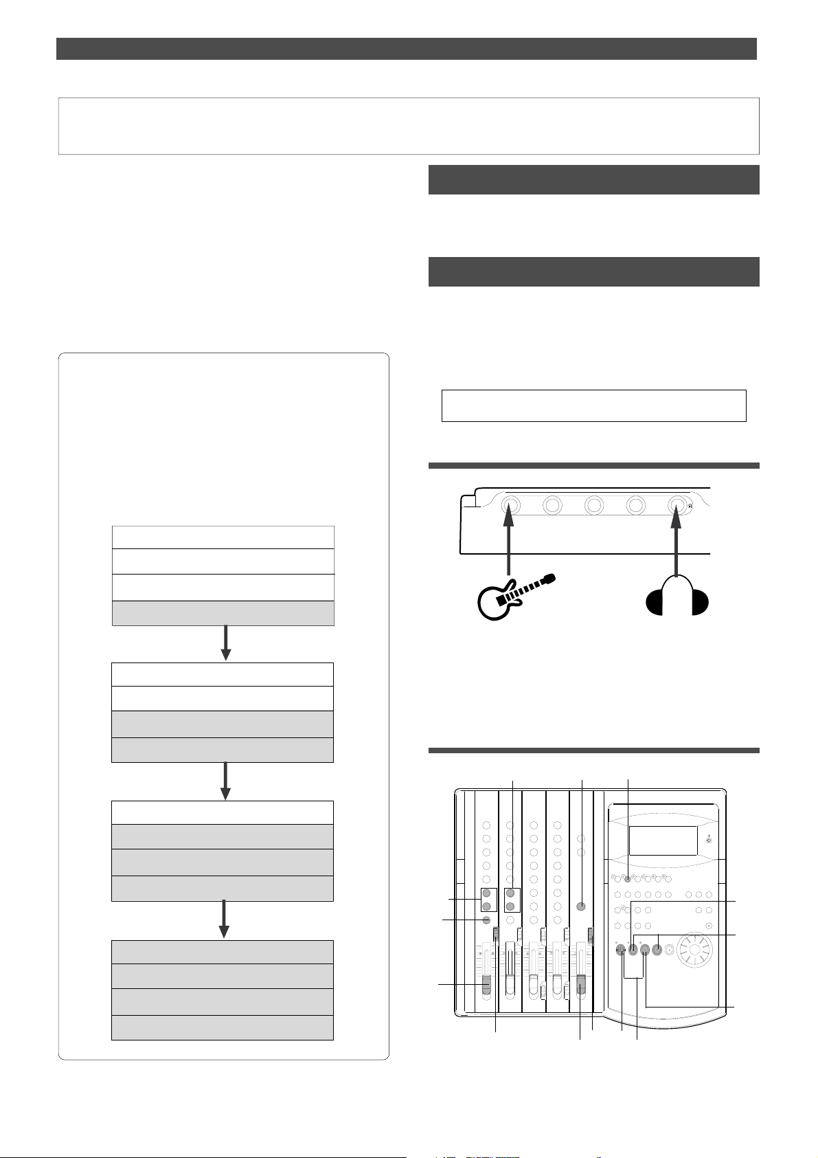
Basic Application (Basic Multitrack Recording)
Basic Multitrack Recording
You learned how to record one sound source to one track
in the “Basic Recording and Playback” chapter.
This chapter explains how to perform multitrack recording, which is, of course, the primary application of a
multitracker.
Multitrack recording is the term for a series of processes in
which you record various sound sources to different tracks
and combine them into two mixes (L and R).
This recording involves one important process called “overdubbing,” in which you record an additional sound source
to a different track while monitoring the input sound and
listening to the already-recorded sound play back.
As an example of the steps involved in overdubbing, we record the
following instruments to tracks 1–4.
1. Record a drum machine to track 1.
2. Record an electric bass to track 2 while listening to track 1
playback.
3. Record an electric guitar to track 3 while listening to tracks 1
and 2 playback.
4. Record the vocal to track 4 while listening to tracks 1–3
playback.
Recording a drum machine to track 1
Record the drum machine sound to track 1 as per to the
“Basic Recording and Playback” chapter.
Overdubbing the bass to track 2
This step assumes that only one Program has been set up.
If multiple Programs have already been set up, first select
the desired Program. Do not select another Program until
you finish a series of overdub operations.
Refer to “Using the Program Change function” on page 37
for more information on changing the Programs.
* Initialize the FD-4.
Connecting a sound source
21
3
4
Track 1 -> Drum machine
Track 2
->
Electric Bass
Track 1
->
Drum machine
Track 3
->
Electric Guitar
Track 2
->
Electric Bass
Track 1
->
Drum machine
->
Track 4
Track 3
Track 2
Track 1
Vocal
->
Electric Guitar
->
Electric Bass
->
Drum machine
1.Connect the electric bass to input jack 1.
You may connect the bass to any input jack.
If you connect it to input jack 3 or 4, set the LEVEL switch
to [H].
Setting the switch and knob
8
EQ
EQ
8
3
10
2
7
4
1
5
6
12
13
11
9
32
Page 33
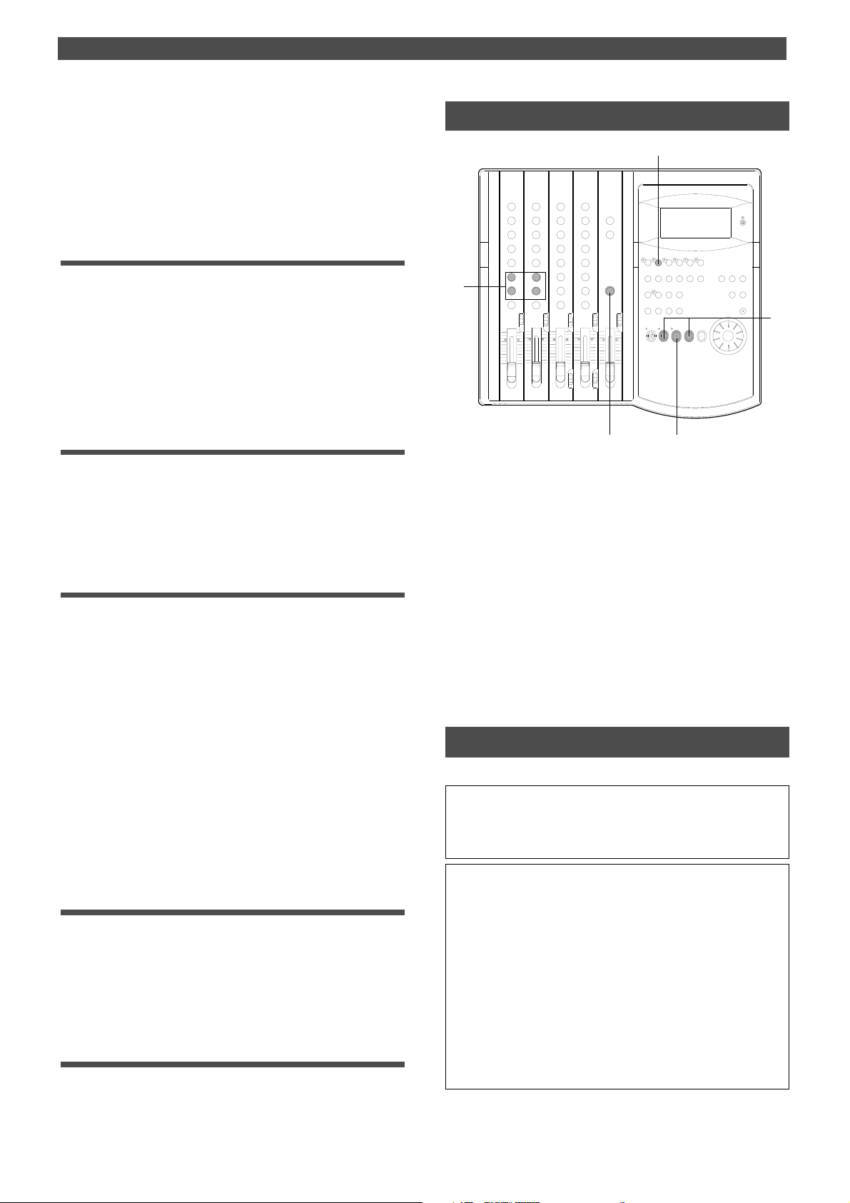
Basic Application (Basic Multitrack Recording)
1.Set the channel 1 INPUT SEL switch to [INPUT].
2.Turn the channel 1 PAN knob all the way to [R].
3.Press the RECORD RACK select key [2/R] to set track 2 to
READY mode.
The 2/R LED flashes.
4.Set the SELECTOR in the monitor section to [MON].
Adjusting the recording level
5.Raise the master fader L/R to [7–8].
6.Press the RECORD button.
The RECORD LED flashes, and the READY track 2 enters
input monitoring mode.
7.Raise the channel 1 input fader to [7–8] and play the bass.
While observing level meter 2, use the input fader and
equalizer to obtain the optimum tonal color and
recording level.
Monitoring the electric bass sound
8.Use the channel 2 MON mix section to adjust the monitoring
level of the electric bass sound.
Turn the MON knob toward [TRK 2] and turn the
MASTER knob in the monitor section.
Use the MON PAN knob to adjust the stereo image of the
monitoring sound.
Practicing overdubbing
Monitor the electric bass sound while listening to the playback of the drum machine sound on track 1.
9.Press the PLAY button to play the recorder .
At this time, the LED of the READY track and the RECORD
LED keep flashing.
10. Use the channel 1 MON mix section to adjust the track 1
playback sound.
Play the electric bass while monitoring the drum machine
sound on track 1.
You can monitor the drum machine sound (playback
monitoring) and the electric bass sound (input
monitoring) at the same time.
Use the MON knobs and MON PAN knobs of channels 1
and 2 to adjust the volume level and balance.
At this stage, the bass sound is not recorded. Practice
your performance until you are satisfied.
Starting overdubbing
1 1. Press the REWIND button while pressing the STOP button
to locate the beginning of the Program.
12. Press the PLAY button while pressing the RECORD
button.
Play the electric bass while listening to the drum machine
sound on track 1.
Quitting overdubbing
13. Press the STOP button to stop recording.
Listening to the overdubbed sound
2
EQ
EQ
4
1
4
1.Press the REWIND button while holding down the STOP
button to locate the beginning of the Program.
2.To avoid accidental recording, turn the RECORD TRACK
select key 2/R off.
3.Press the PLAY button to play back from the beginning.
4.Adjust the playback sound of tracks 1 and 2 in the channels
1 and 2 MON mix section.
The following table shows the switch settings for overdubbing on tracks 3 and 4. (Refer to next page.)
In this example session, we record the electric guitar to track
3 and the vocal to track 4 in the same way as we overdubbed track 2.
3
Undo/redo overdubbing
You can undo or redo overdubbing.
• Press the UNDO/REDO key after recording is completed to
restore the conditions that existed prior to the overdubbing.
• Press the UNDO/REDO key again to restore the conditions that
existed after the overdubbing.
<Note>
The Undo/Redo function is effective only when the FD-4 is stopped.
The Undo/Redo is ineffective if you perform one of the following
operations after you finish recording.
1. When a new recording is made.
2. When a new editing is executed (such as Copy & Paste, Move &
Paste, Erase).
3. While in the AUTO PUNCH ON mode, when the AUTO PUNCH
IN point is passed in the PLA Y (or RECORD) mode.
4. When the power is momentarily switched off.
5. When the program is changed.
6. When the disk is ejected.
33
Page 34
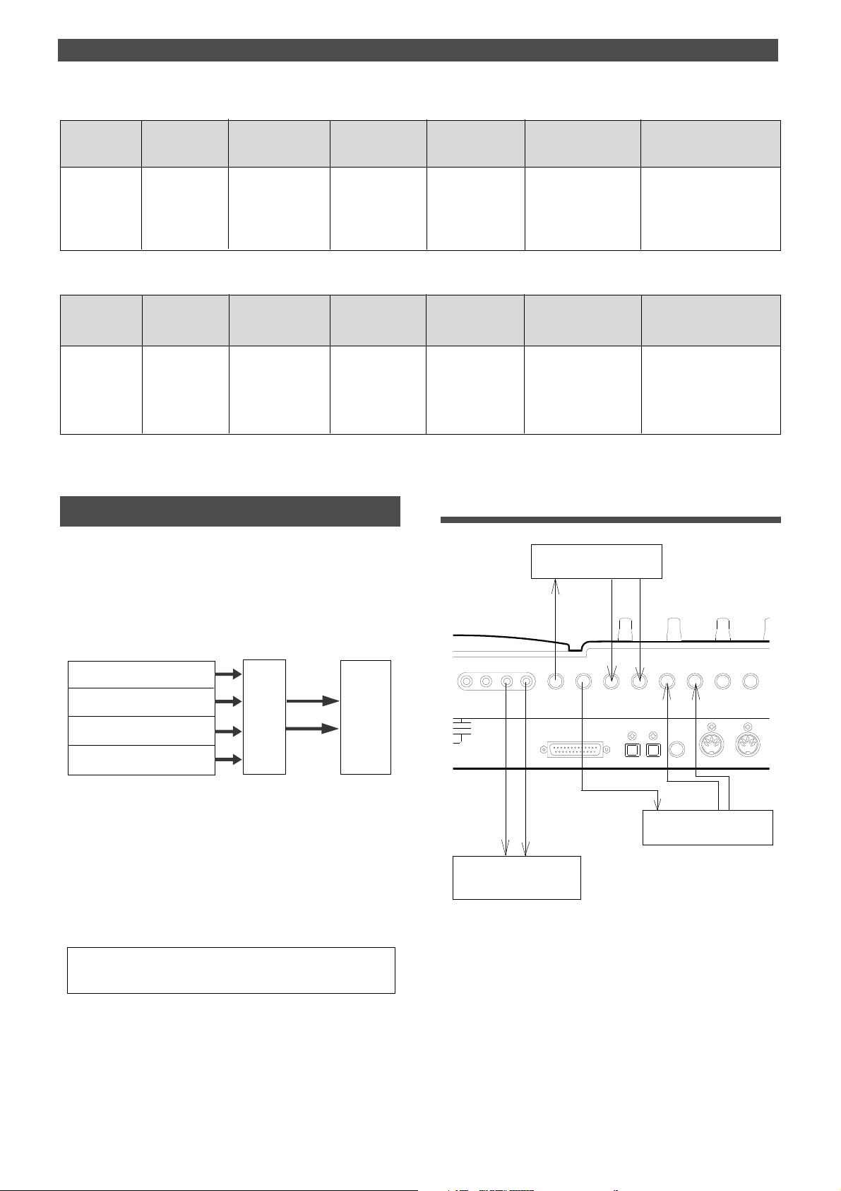
Basic Application (Basic Multitrack Recording)
R MON OUT L
R ST OUT L
AUX RTN 1
R MONO/L
AUX RTN 2
R MONO/L
2 AUX SEND 1
4 INSERT 3
SCSI
OUTIN
DATA
IN
MIDI
OUT
PUNCH
IN/OUT
DATA
MIDI
Settings for overdubbing the electric guitar to track 3
INPUT jack
Any INPUT jack
REC TRACK
select key for
track READY
3/L
Settings for overdubbing the vocal to track 4
INPUT jack
Input jack 3 or 4
(on the front
panel or the rear
panel), with the
LEVEL switch
set to [L]
REC TRACK
select key for
track READY
4/R
INPUT SEL switch
position
Set the switch of the
channel to which the
sound source is
connected to INPUT.
INPUT SEL switch
position
Set the switch of the
channel to which the
sound source is
connected to INPUT.
Turn the knob of the
channel to which the
channel to which the
PAN knob
adjustment
sound source is
connected all the
way to L.
PAN knob
adjustment
Turn the knob of the
sound source is
connected all the
way to R.
Monitor section’s
SELECTOR
position
Set to MON.
Monitor section’s
SELECTOR
position
Set to MON.
Adjusting the
monitoring level of the
recording track.
Use the MON mix section
of channel 3 to adjust the
monitoring level of the
sound being recorded to
track 3.
Adjusting the
monitoring level of the
recording track.
Use the MON mix section
of channel 4 to adjust the
monitoring level of the
sound being recorded to
track 4.
Adjusting the monitor level
of track 1 and 2.
Use the MON mix section of
channels 1 and 2 to adjust
the monitoring level of
tracks 1 and 2 respectively.
Adjusting the monitor level
of track 1 and 2.
Use the MON mix section of
channels 1, 2 and 3 to adjust
the monitoring level of
tracks 1, 2 and 3 respectively.
Mixdown
Mixdown is the final process in multitrack recording, in
which you combine multiple recorded track data into stereo L and R (2 mixes) and copy (dub) to the master recorder.
You can apply effects to the recordings on tracks 1–4 via
Aux send/return, equalize the signals, and adjust the overall volume level and stereo image before mixdown.
Track 4
Track 3
Mix
Track 2
Track 1
To output signals for mixdown (stereo bus L/R output), the
FD-4 is equipped with DATA OUT jacks that output digital
signals (S/P DIF format), as well as the STEREO OUT L/R
jacks for analog output.
This makes it possible to perform high-quality digital
mixdown without tonal deterioration onto an external DAT
machine with optical inputs.
Refer to “Advanced Operation” for more information on
digital mixdown and other mixes using advanced techniques.
• Initialize the FD-4.
• Use two effect units, reverb and chorus, for effects.
Master
Recorder
Connecting external devices
Effect unit (Chorus)
2
Effect unit (Reverb)
1
3
Master Recorder
1.Connect the input and output jacks of the reverb unit to the
AUX SEND1 and AUX RTN1 of the FD-4 respectively .
2.Connect the input and output jacks of the chorus unit to the
AUX SEND2 and AUX RTN2 of the FD-4 respectively .
3.Connect the input jacks of the master recorder (DAT or
analog recorder) to the STEREO OUT L/R of the FD-4.
34
Page 35
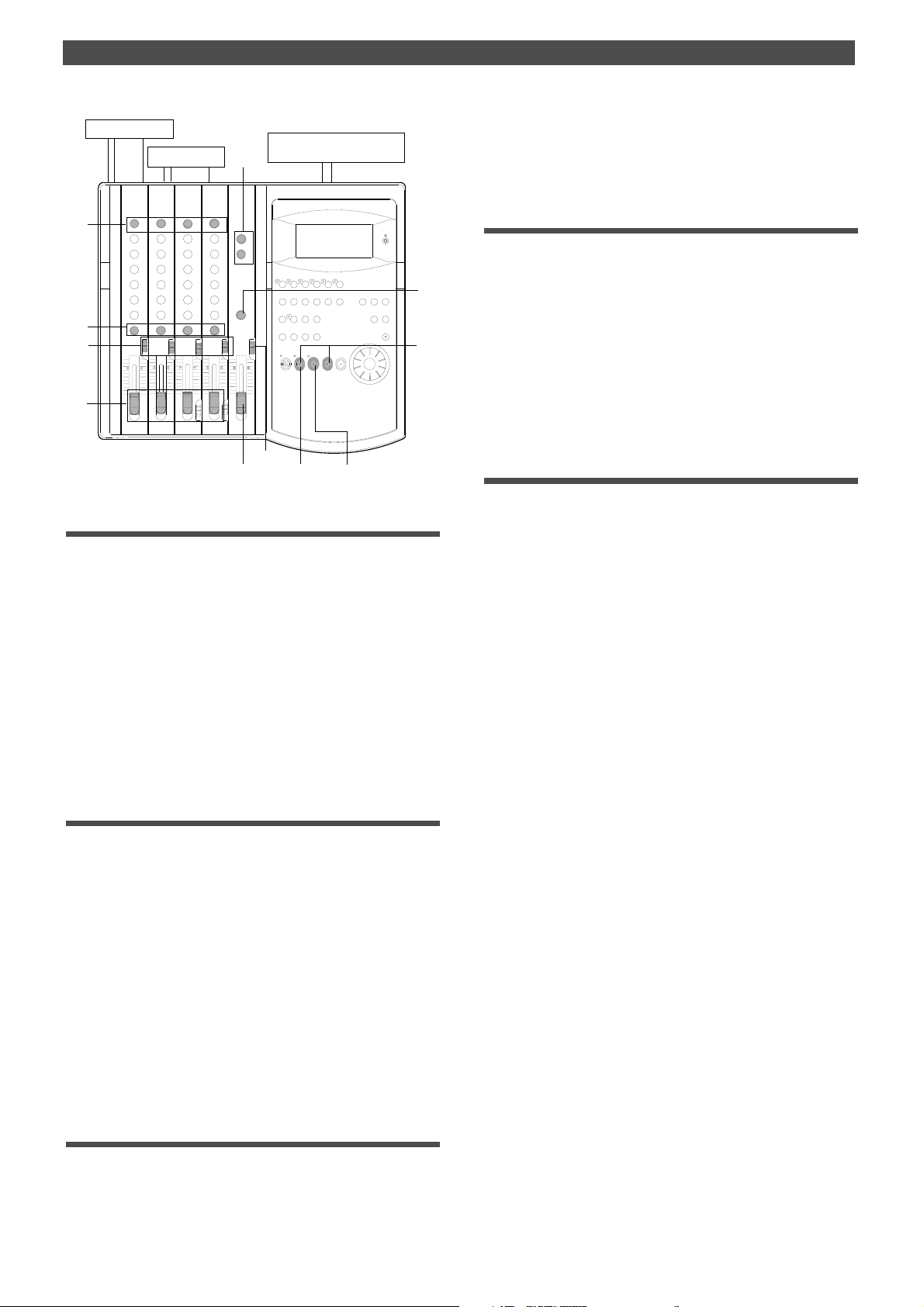
Basic Application (Basic Multitrack Recording)
10
5, 12
Master Recorder
Effect unit 1
9
Effect unit 2
EQ
EQ
2
1
7
3
4, 8
14
6, 13
Setting the switch and knob on the FD-4
1.Set the INPUT SEL switches of channels 1–4 to [TRK].
In this way, the output from recorded tracks 1–4 will be
routed to the corresponding input channel faders for
equalization and effect processing.
2.Set the channel PAN knobs accordingly.
There is no rule on the position of the PAN knobs.
The settings would differ depending on the type of the
instrument you recorded or the feel of your song.
You can, for example, pan a given instrument to the left
and the vocal to right. Follow your intuition.
3.Set the SELECTOR in the monitor section to [L/R].
4.Raise the master fader L/R to [7–8].
11
Turn the knob toward [AUX 1] to apply reverberation;
turn it toward [AUX 2] to apply chorus.
10. Use the AUX RTN 1 and AUX R TN 2 knobs to adjust the
input level from the effect units to the stereo bus L/R.
Mixdown
1 1. Press the REWIND button while holding down the STOP
button to locate the beginning of the Program.
7
12. Start recording on the master recorder.
Adjust the input level on the master recorder so that its
level meters indicate almost the same level as the FD-4’s
level meters L/R.
13. Press the FD-4’s PLA Y button to play the Program from the
beginning.
Operate the master faders L/R to fade the mixdown sound
in and out.
Quitting mixdown
14. Stop the master recorder and the FD-4.
Setting the output level and the master recorder
5.Set the master recorder to recording standby mode.
You should be able to check the recording level.
6.Press the PLAY button to play back the Program from the
beginning.
7.Raise the channel faders and turn the MASTER knob in the
monitor section gradually to monitor the sound.
Use the channel faders to adjust the track playback levels
while monitoring the sound.
At this time, check the level meters L and R and adjust
the faders so that the [OL] section of the meter will not
light up with the maximum level.
8.When you obtain a satisfactory balance, use the master
fader L/R to adjust the final output level.
Also adjust the input level on the master recorder.
Settings for the effect units
9.Turn the AUX knob for the channel signal to which you wish
to apply effects toward [AUX 1] or [AUX 2].
35
Page 36
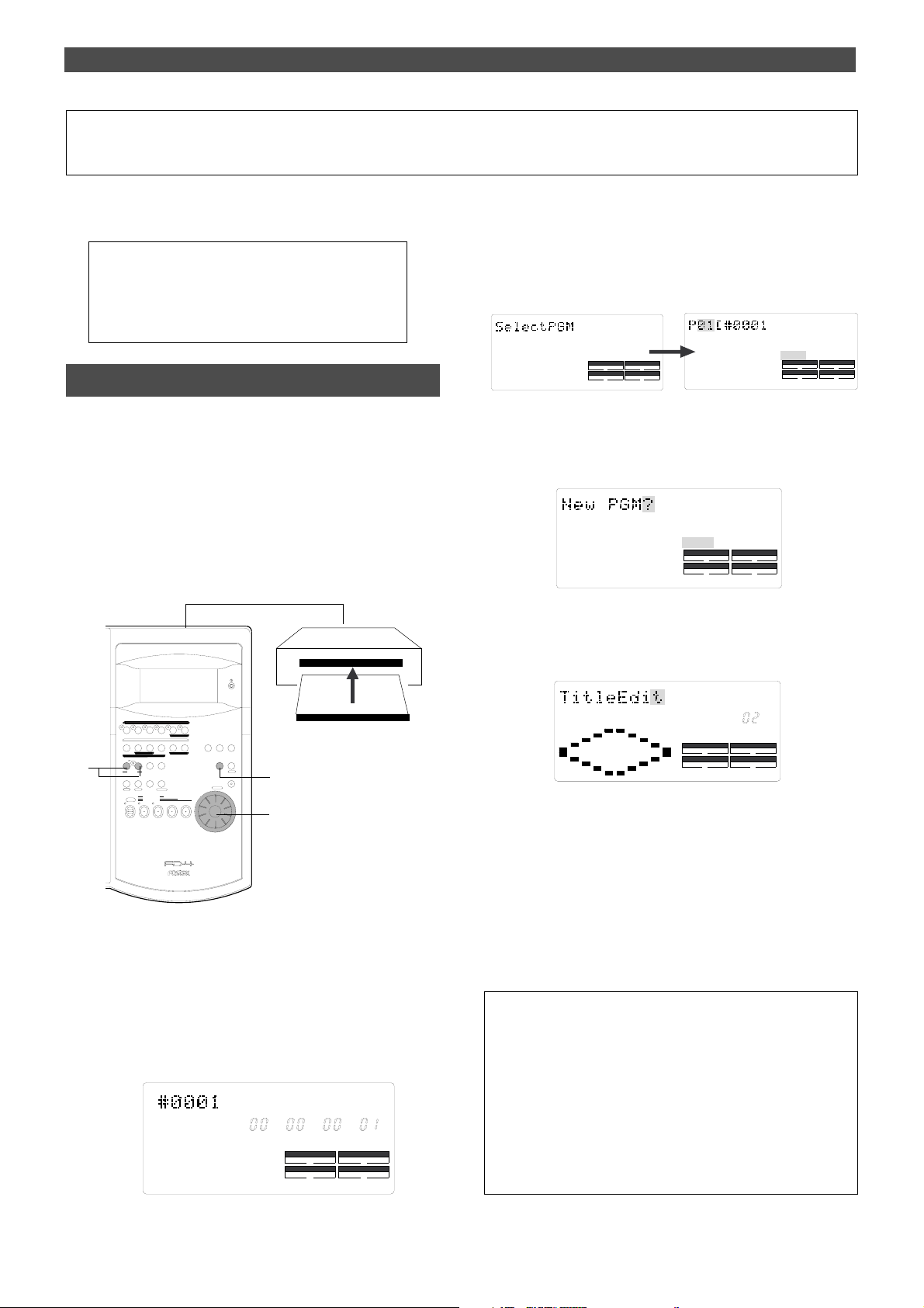
Handling Programs
DRIVE
AUTO A.PUNCH
SYNC OUT
CLK
SCSI
Handling Programs
This chapter explains how to handle Programs.
It covers the following topics:
1. Creating a new Program
2. Using a Program Change function
3. Deleting a Program
4. Editing a Program title
Creating a new Program
You can manage individual songs by setting multiple Programs on the disk as explained in the “Managing songs by
Program Change function” section of the “Before Starting”
chapter. You can create up to 99 Programs can be created
as long as the disk space allows.
When you format a disk, one Program will be automatically
created. Follow the steps below to create a new Program (in
addition to the Program created on the disk during the
format operation).
1
1
3.While holding down the HOLD/> key, press the STORE key.
(Alternatively, while holding down the STORE key , press the
HOLD/> key.)
[Select PGM] appears on the display briefly, then changes
to a flashing “01” ([#0001 of PGM 01) and [SURE?] flash.
([#0001] is the default name of PGM 01.)
?
SURE
SYNC OUT
CLK
AUTO A.PUNCH
DRIVE
SCSI
4.Turn the JOG dial clockwise.
The question marks “?” of [New PGM ?] and [SURE?] flash.
This indication asks you if you wish to set a new Program
(Program 2).
?
SURE
SYNC OUT
CLK
AUTO A.PUNCH
DRIVE
SCSI
5.Press the EXECUTE/YES key.
The FD-4 automatically enters [Title Edit ?] menu in SETUP
mode. You can enter a title for Program 2. ([t] and [?]
flash alternately.)
RECORD TRACK
RL
4/R3/L2/R
3
1/L
START IN OUT
HOLD/ STORE
SHIFT
PUNCH
RECORD
ADD. TRACK
PREVIEW
END IN OUT
AUTO PUNCH
CLIPBOARD
AUTO RTN
UNDO/
REDOEDIT
PGM SEL
AUTO RTN
VARI
AUTO PLAY
PITCH
LOCATE
P. EDIT
LOC MEM
CLIPBOARD PLAY
LOCATE ABS 0
AUTO
LOCATE REC END
TIME BASE
SELDISP SEL
SETUP
EXIT
EXECUTE
/YES
/NO
ELECT
ACCESS
SHUTTLE
JOG
F FWDREWINDPLAYSTOP
5, 6, 7
2
4
DIGITAL MULTITRACKER
1.Turn on the power to the FD-4 and a connected SCSI drive.
2.Insert a formatted disk into the SCSI drive.
The FD-4 displays [Initial..], [(SCSI drive name and ID
number)], [(Recording mode, such as [Normal])], then
the top of ABS Time Base (ABS 0).
The current Program is [PGM 01]. [#0001] is the default
name of PGM 01.
44.1kHz
ABS
SMF
SYNC OUT
CLK
AUTO A.PUNCH
DRIVE
PGM
SCSI
SETUP
PGM
SYNC OUT
CLK
AUTO A.PUNCH
DRIVE
SCSI
6.Press the EXECUTE/YES key again.
A default title (#0002) appears on the display, with “#”
and [SURE?] flashing. This means that you can enter a
name for the new Program.
If you prefer the default name, press the EXECUTE/YES
key again. If you wish to name the Program with a unique
title, continue the steps below. In either case, you can
change the title later, as explained in “Editing a Program
title.”
To enter a title:
• Turning the JOG dial will enter a character or number at the
location of the flashing cursor. Y ou can enter up to 16 characters,
nine of which will appear on the display.
• T o move the flashing cursor, press the HOLD/> key , the REWIND
button, or the F FWD button. The F FWD button is the most
convenient.
• You can enter the following characters and numbers:
36
Page 37
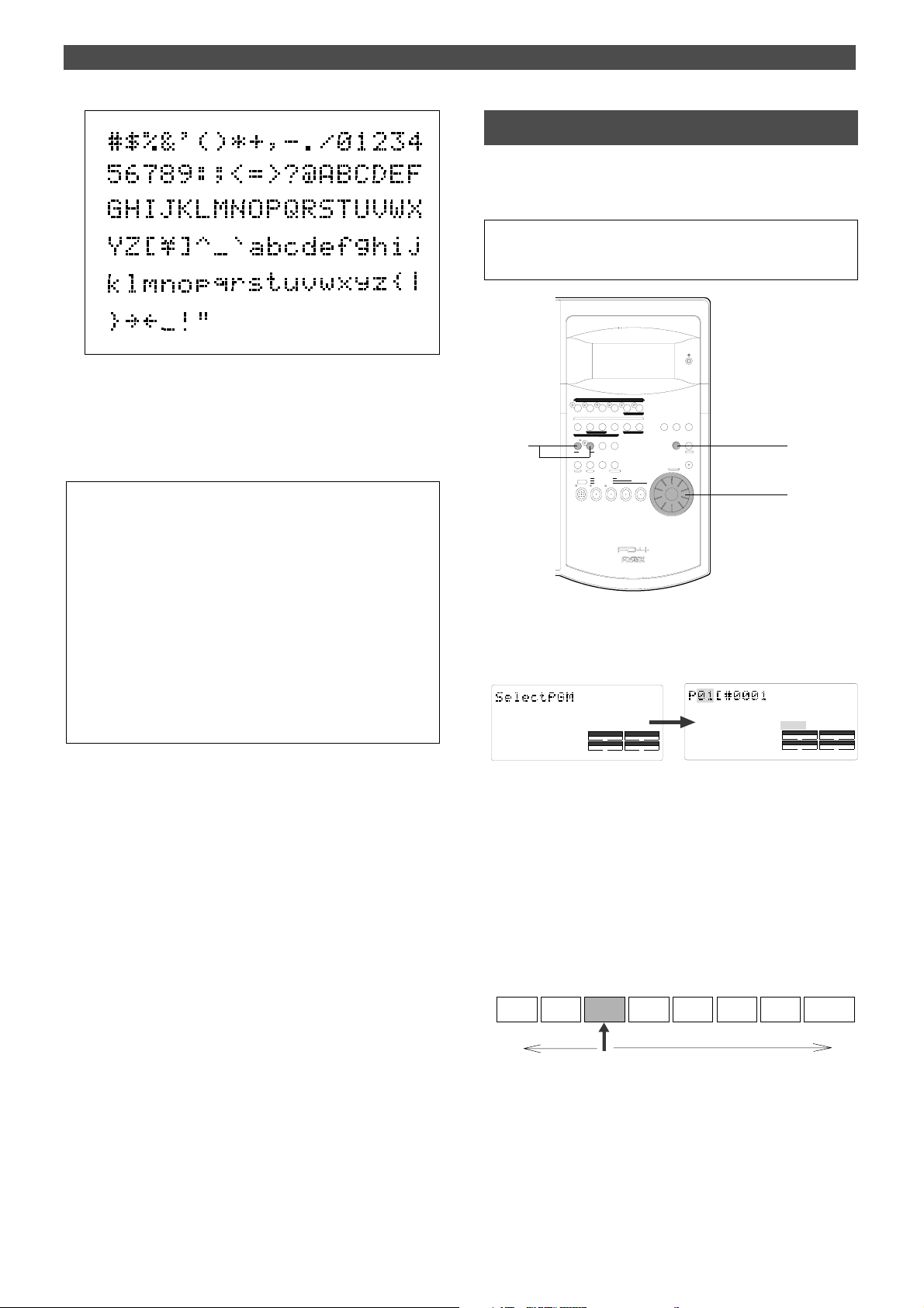
7.When you finish entering the title, press the EXECUTE/YES
key.
Program 2 (PGM 02) and its title are set.
The display shows the ABS Time Base indication of the
Program.
<Important!>
• When you create a new Program by selecting the [New PGM
?] menu, a new Program is created with an increment
number.
That is, if only one Program exists and when you create a
new Program, it will be named Program 2.
If Programs 1–5 already exist, a new Program number will be
6.
• If there is insufficient recording space on the disk, you cannot
create the new Program. Each time you create a new
Program, the recordable area on the disk will decrease.
Handling Programs
Using the Program Change function
If multiple Programs exist on the disk, you need to select a
Program to record, play, or edit. This section describes
how to select a Program.
<Note>
You cannot use the Program Change function when the FD-4 is in SETUP
mode.
RECORD TRACK
RL
4/R3/L2/R
1
1/L
START IN OUT
HOLD/ STORE
PGM SEL
SHIFT
AUTO
PUNCH
RECORD
ADD. TRACK
PREVIEW
END IN OUT
AUTO PUNCH
CLIPBOARD
AUTO RTN
UNDO/
REDOEDIT
AUTO RTN
VARI
AUTO PLAY
PITCH
LOCATE
P. EDIT
LOC MEM
CLIPBOARD PLAY
LOCATE ABS 0
LOCATE REC END
F FWDREWINDPLAYSTOP
TIME BASE
SELDISP SEL
SETUP
EXIT
EXECUTE
/YES
/NO
ELECT
ACCESS
SHUTTLE
JOG
3
2
DIGITAL MULTITRACKER
1.When the FD-4 is stopped, press the STORE key while
holding down the HOLD/> key. (Or press the HOLD/> key
while holding down the STORE key.)
?
SYNC OUT
CLK
AUTO A.PUNCH
DRIVE
SCSI
SURE
SYNC OUT
CLK
AUTO A.PUNCH
DRIVE
SCSI
2.Turn the JOG dial to select the desired Program number
(flashing).
Rotating the JOG dial counter-clockwise decreases the
number, and rotating it clockwise increases the number.
If you turn the JOG dial clockwise all the way, [New PGM
?] will be selected.
Select [New PGM ?] to create a new Program as mentioned
in the previous section “Creating a new Program.”
For example, you can select one of seven Programs as
follows:
PGM 01
PGM 02
You can select up to PGM
01 in this direction.
PGM 03 PGM 04 PGM 05 PGM 06 PGM 07
You can select from PGM 03 up to New
PGM in this direction.
New PGM
3.Press the EXECUTE/YES key.
The ABS Time Base indication for the selected Program
appears.
In this way, you can be sure to select a Program before
you start working.
37
Page 38

Handling Programs
Deleting a Program
This section explains how to delete an unnecessary
Program.
Deleting an unnecessary Program will expand the recordable area, making your work flow more smoothly, since
recording or editing requires sufficient recordable area (free
space on the disk). Use the [Del. PGM ?] menu in SETUP
mode to delete a Program.
<Notes on deleting a Program>
• You can delete only the currently-selected Program. Refer to
the previous section, “Using a Program Change function,” for
information on how to select the desired Program before you
proceed to delete the Program.
• If only one Program exists and you try to delete it, data
contained in the Program will be deleted, but the Program itself
will remain.
For example, assume that PGM 01 –07 exist and you try to
delete PGM 05. Program number 05 will remain, but the data
inside PGM 05 will be replaced with the data of PGM 06.
The subsequent Programs’ data will move in the same way.
Therefore, it will appear that PGM 07 has been deleted.
If you delete the last Program (PGM 07 in this example), PGM
07 will be completely deleted.
PGM 02 PGM 03 PGM 04
PGM 01
PGM 05
PGM 06 PGM 07
1.Press the SETUP key while the FD-4 is stopped.
The FD-4 enters SETUP mode, and displays the first
hierarchy of the SETUP menu that was displayed before
youturned off the power.
The default setting is [Sign. Set ?] menu (setting a time
signature).
44.1kHz
SETUP
SYNC OUT
CLK
AUTO A.PUNCH
DRIVE
SCSI
2.Turn the JOG dial to select the first hierarchy of the [Del.
PGM ?] (deleting a Program) menu.
Alternatively, you can use the HOLD/> key, the REWIND
button, or the F FWD button.
44.1kHz
SETUP
PGM
SYNC OUT
CLK
AUTO A.PUNCH
DRIVE
SCSI
3.Press the EXECUTE/YES key.
The number of the Program to be deleted appears and
[SURE ?] flashes.
If you try to delete PGM 05, only the data of
PGM 05 will be deleted and the data of PGM
After deleted
PGM 02 PGM 03 PGM 04
PGM 01
06 will move into PGM 05.
PGM 05
PGM 06
• You cannot use the Undo/Redo function to delete Programs.
Make sure that you delete the correct Program.
RECORD TRACK
1/L
START IN OUT
AUTO PUNCH
AUTO RTN
HOLD/ STORE
PGM SEL
VARI
PITCH
SHIFT
P. EDIT
AUTO
PUNCH
RECORD
AUTO RTN
AUTO PLAY
CLIPBOARD PLAY
LOCATE ABS 0
LOCATE REC END
4/R3/L2/R
PREVIEW
END IN OUT
UNDO/
REDOEDIT
LOCATE
LOC MEM
ADD. TRACK
CLIPBOARD
RL
TIME BASE
SETUP
SELDISP SEL
EXIT
EXECUTE
/YES
/NO
ELECT
ACCESS
SHUTTLE
JOG
F FWDREWINDPLAYSTOP
1
3, 4
2
44.1kHz
SETUP
SURE ?
SYNC OUT
CLK
AUTO A.PUNCH
DRIVE
PGM
SCSI
T o cancel the delete operation, press the EXIT/NO key while [SURE ?]
is flashing. Each time you press the button or key, the FD-4 will return to
a higher level in the hierarchy, and finally exit SETUP mode.
4.Press the EXECUTE/YES key again.
When the FD-4 displays [Deleting...] and finishes
deleting the Program, the data of the next Program
number moves in, and its ABS time appears.
• To check the REMAIN time and free space, press the DISP SEL key
to display the [REMAIN] indication after the Program is deleted.
38
DIGITAL MULTITRACKER
Page 39
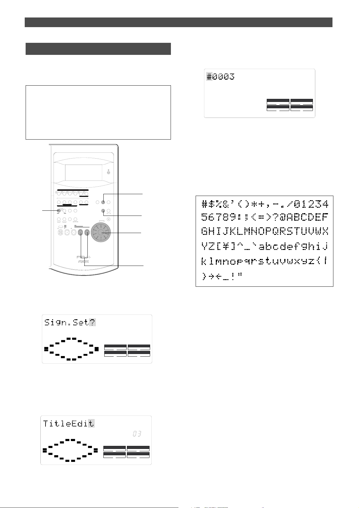
Handling Programs
Editing a Program title
You can name the Program as explained in the “Creating a
new Program” section. You can also change the title later
by using the [Title Edit ?] menu in SETUP mode.
<Note>
You can edit the title of the selected Program before you select
SETUP mode. You cannot select a Program after the FD-4
enters SETUP mode. Be sure to select the desired Program
using the steps explained in the “Using the Program Change
function” section.
RECORD TRACK
4
1/L
START IN OUT
AUTO PUNCH
HOLD/ STORE
PGM SEL
VARI
PITCH
SHIFT
P. EDIT
AUTO
PUNCH
RECORD
AUTO RTN
CLIPBOARD PLAY
LOCATE REC END
AUTO RTN
AUTO PLAY
LOCATE ABS 0
4/R3/L2/R
PREVIEW
END IN OUT
UNDO/
REDOEDIT
LOCATE
LOC MEM
ADD. TRACK
CLIPBOARD
RL
TIME BASE
SETUP
SELDISP SEL
EXIT
EXECUTE
/YES
/NO
ELECT
ACCESS
SHUTTLE
JOG
F FWDREWINDPLAYSTOP
1
3, 5
1, 4
3.Press the EXECUTE/YES key.
The currently-selected Program title appears with the leftmost character flashing.
44.1kHz
SETUP
SYNC OUT
CLK
AUTO A.PUNCH
DRIVE
SCSI
4.Press the HOLD/> key, the REWIND button, or the F FWD
button to move the flashing cursor, and use the JOG dial to
enter characters or numbers.
To move the flashing cursor, press the HOLD/> key, the
REWIND button, or the F FWD button. The F FWD button
is the most convenient.
You can enter up to 16 characters, nine of which will
appear on the display.
You may enter the following characters and numbers:
DIGITAL MULTITRACKER
4
1.Press the SETUP key while the FD-4 is stopped.
The FD-4 enters SETUP mode and displays the first
hierarchy level of the SETUP menu that was selected
before you turned off the power.
44.1kHz
SETUP
SETUP
DRIVE
44.1kHz
SCSI
SYNC OUT
CLK
AUTO A.PUNCH
2.Turn the JOG dial to select the first hierarchy level of the
[Title Edit ?] (title edit) menu.
The currently-selected Program number also appears.
You can also use the HOLD/> key, the REWIND button, or
the F FWD button to select the first hierarchy level
display.
5. After you enter the title, press the EXECUTE/YES key .
The new title is confirmed, and the ABS time value of the
Program appears.
SYNC OUT
CLK
AUTO A.PUNCH
DRIVE
PGM
SCSI
39
Page 40
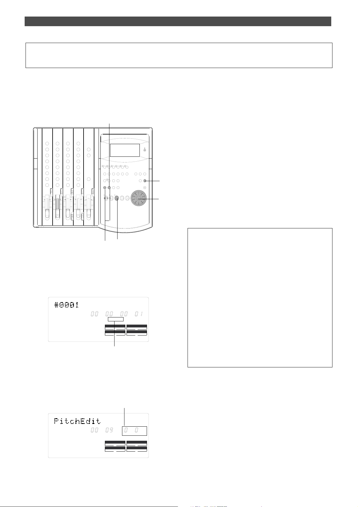
Special Application (Playback in Vari pitch mode)
Playback in Vari Pitch Mode
This chapter explains how to change the playback speed of
the recorder using the Vari Pitch function. You can set Vari
Pitch in the range of +6.0% to –6.0% in 0.1% steps.
The VARI PITCH key turns Vari Pitch mode on and off.
2, 6, 7
EQ
EQ
5
4
13
1.Press the PLAY button to play the FD-4.
4.Set the desired pitch data using the JOG dial.
You can hear the changes in playback speed.
5.After you set the pitch data, press the EXIT/NO key.
The FD-4 exits from Vari Pitch data edit mode and
continues playing with the Vari Pitch you just set.
6.To turn off Vari Pitch mode, press the VARI PITCH key. (The
[VARI PITCH] indicator turns of f.)
Vari Pitch mode is cancelled, and the FD-4 resumes
playback at normal speed.
7.If you wish to play back data at the current Vari Pitch again,
press the V ARI PITCH key to turn the mode on.
You can turn the Vari Pitch function on and off and edit the
pitch data while the FD-4 is playing or stopped, but not
during recording.
However, if the Vari Pitch function has already been turned
on and the pitch data was specified before you start
recording, the FD-4 will record using the current Vari Pitch.
<Note>
Even if the pitch data is 0.0% (no speed change), pressing the
VARI PITCH key will turn on the [VARI PITCH] indicator on the
display . In other words, the [VARI PITCH] display indicates that the
Vari Pitch function is turned on.
2.Press the VARI PITCH key.
The [VARI PITCH] indicator lights up on the display,
indicating that Vari Pitch mode is turned on.
44.1kHz
ABS
VARI PITCH lights up to indicate Vari
Pitch mode is turned on.
SMF
VARI PITCH
SYNC OUT
CLK
AUTO A.PUNCH
DRIVE
PGM
SCSI
3.Press the VARI PITCH key again while holding down the
SHIFT key.
The FD-4 enters Vari Pitch data edit mode, and the
current pitch data flashes on the display.
The current pitch data flashes.
44.1kHz
ABS
SM
VARI PITCH
SYNC OUT
CLK
AUTO A.PUNCH
%
.
PGM
DRIVE
SCSI
<Note>
The Vari Pitch function is automatically turned off and the [VARI
PITCH] indicator is turned off under the following conditions:
• You have turned on the power to the FD-4. (The pitch data will
be reset to 0.0%.)
• You have set “Slave mode setting” in SETUP mode to ON. (The
pitch data previously set will be maintained.
• You have specified a track for “Digital input track setting” in SETUP
mode, and [DIGITAL] lights up on the display. (The pitch data
previously set is retained.)
40
Page 41
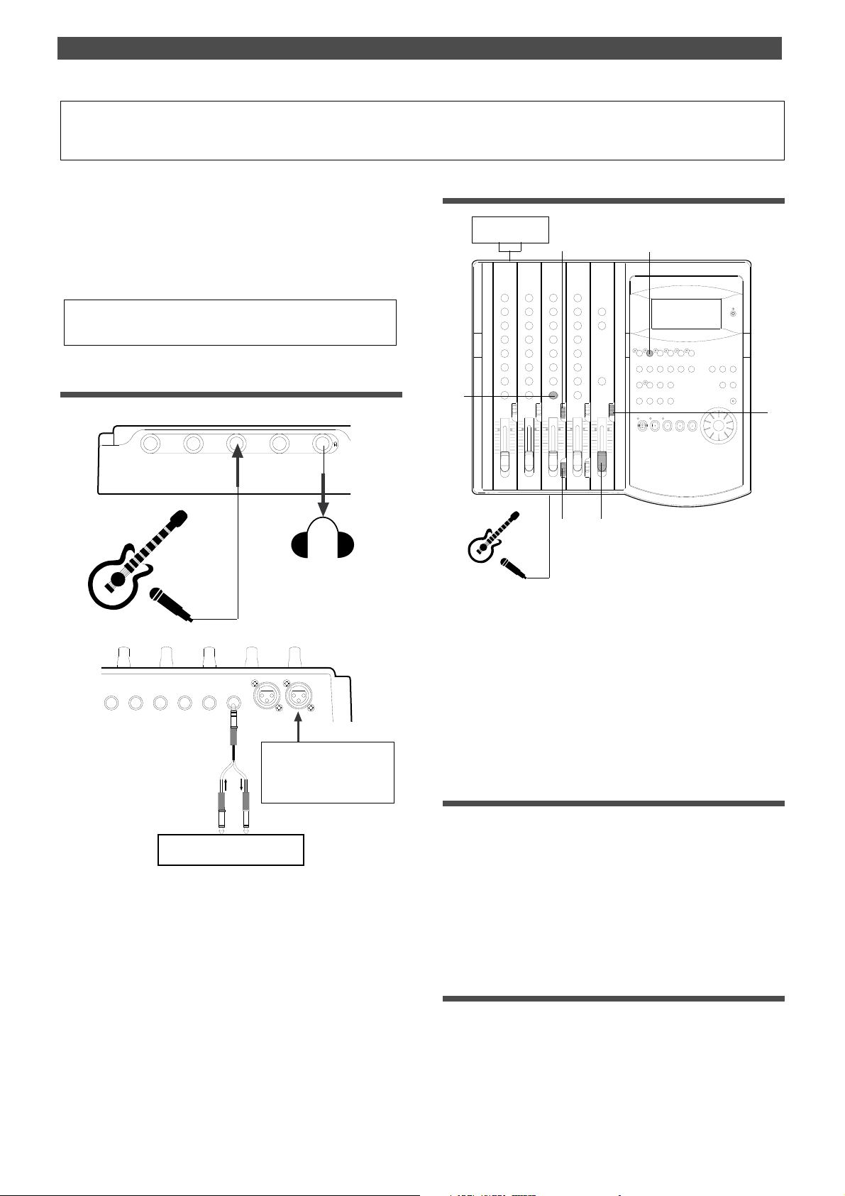
Special Application (Recording to a Metronome Sound)
Recording to a Metronome Sound
This chapter explains how to record your performance while
you are playing an instrument accompanied by a metronome based on the time signature and tempo specified in
the Tempo Map. The metronome sound is output from track
4.
For example, record the acoustic guitar using a microphone
to track 2 while using a compressor/limiter.
• Initialize the FD-4 before the operation.
• If multiple Programs exist, first select the desired Program.
Connecting a sound source and a effect unit
21
3
4
Setting the switch and knob
Compressor/limiter
2
EQ
EQ
5
6
1
4
3
INPUT 3
AUX RTN 2
R MONO/L
AUX RTN 1
R MONO/L
4 INSERT 3
INPUT 4
If the microphone has a balanced (XLR) connector, use
INPUT 3 (XLR) jack on the
rear panel.
Compressor/limiter
1.Connect a microphone to input jack 3.
If the microphone has a balanced (XLR) connector, use
INPUT 3 (XLR) jack on the rear panel.
2.Connect a compressor/limiter to INSERT jack 3 on the rear
panel.
The compressor/limiter will be applied to channel 3
signal.
1.Set channel 3 LEVEL switch to [L].
2.Set channel 3 INPUT SEL switch to [INPUT].
3.Set the SELECTOR in the monitor section to [MON].
4.Set the RECORD TRACK select key 2/R to READY.
5.Turn channel 3 PAN knob all the way to R.
6.Raise the master fader L/R to [7–8].
Creating a Tempo Map
1.Set the time signature using the “Setting a time signature”
menu in SETUP mode.
Refer to the “Setting a time signature” section on page
82.
2.Set a tempo for a given point using the “Setting a tempo” in
SETUP mode.
Refer to the “Setting a tempo” section on page 83.
Turning the Metronome function on
1.Turn the Metronome function on using the “Setting the
Metronome function” menu in SETUP mode.
Refer to the “Setting the Metronome function” section on
page 85.
41
Page 42
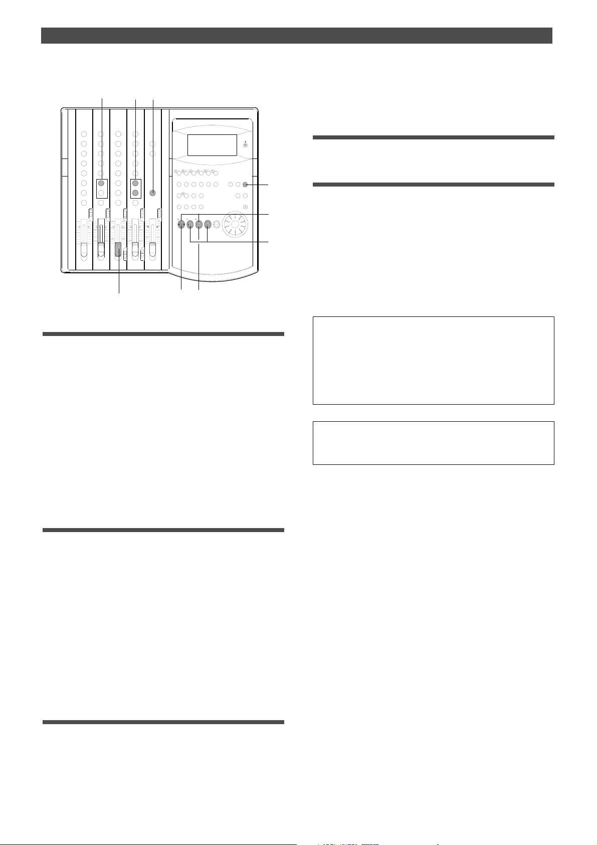
Special Application (Recording to a Metronome Sound)
8
3
3
1 1. Play the guitar in time with the metronome.
The guitar sound is recorded at the recording level
adjusted in step 6.
EQ
EQ
1
10
9
2
6
4
Checking the metronome sound
1.Select the BAR/BEAT/CLK Time Base using the TIME BASE
SEL switch.
2.Start playback from the beginning of the Program.
Even if the selected Program does not have any recorded
data, track 4 outputs the metronome sound and the FD-4
counts time.
Quitting recording
1.Press the STOP button to stop the recorder.
Checking the recorded sound
1.Set the RECORD TRACK select key 2/R to off.
2.Lower channel 3 input fader.
3.Locate the top of the Program and start playback.
4.Turn the channel 2 MON knob to the left to check the
recorded guitar sound.
Since the Metronome function still remains on, you can
hear the metronome sound during playback as you turn
the channel 4 MON knob.
<Note>
When you finish using the Metronome function, turn the function off
in SETUP mode.
<Note>
When the Metronome function is on, you cannot record data on
track 4, nor can you play data recorded on track 4.
3.Turn the MON knob of channel 4 MON mix section toward
TRK, and turn the MASTER knob in the monitor section
gradually.
You will hear the metronome output from track 4 using
the tempo and time signature set in the Tempo Map.
Monitoring the guitar sound and adjusting the
recording level
4.Press the RECORD button.
Track 2 enters input monitoring mode.
5.Play the guitar.
6.Adjust the recording level of the guitar sound using the
channel 3 input fader.
As you raise the input fader, level meter 2 will respond.
7.Adjust the output level on the compressor/limiter.
8.Adjust the guitar monitoring level using the channel 2 MON
mix section.
Use the channel 2 MON knob to adjust the level, and use
the MON PAN knob to adjust the stereo image.
Starting recording
If you wish to re-record the sound, use the Undo/Redo function to
re-start recording as explained in the “Basic Recording and Playback” chapter.
9.Locate the top of the Program.
10. Hold down the RECORD button and press the PLAY
button to start recording.
42
Page 43

Special Application (Punch In/Out Recording)
Punch In/Out Recording
What is Punch In/Out recording?
Punch In/Out recording enables you to record over previously-recorded parts. See the diagram below. For example,
using the Punch In/Out function allows you to change an
unsatisfactory guitar solo.
The FD-4 offers two types of Punch In/Out functions. One
is called Auto Punch In/Out, in which you automatically rerecord a specified part. The other is called Manual Punch
In/Out, in which you record data manually (using your
foot to operate an optional foot switch, model 8051).
Both functions feature “Rehearsal mode” to enable you to
practice repeatedly until you are ready.
Punch In point
Track 4
Track 3
Track 2
Track 1
This part is changed.
• Select a Program for Punch In/Out recording.
• Initialize the FD-4.
<Note>
You can use the Punch In/Out recording only for Real tracks 1–4.
If you wish to use Punch In/Out recording for data on an Additional
track, first move the data to the Real tracks.
Punch Out point
Auto Punch In/Out
To perform Auto Punch In/Out recording, you need to
specify the Auto Punch In point (recording start point) and
the Auto Punch Out point (recording end point).
Storing the edit points
1.Refer to “Storing the edit points” on page 63 to set the Auto
Punch In/Out points.
Store the Auto Punch In point to the AUTO PUNCH IN
key, and the Auto Punch Out point to the AUTO PUNCH
OUT key.
• Refer to page 63 for more information on storing the edit points.
Auto Punch In point
(Strat point)
Track 4
Track 3
Track 2
Track 1
This part is changed.
<Note>
Make sure that you specify an Auto Punch In point that precedes the
Auto Punch Out point. If the Auto Punch Out point precedes the Auto
Punch In point, [Void Out !] appears and you will be unable to perform Auto Punch In/Out recording.
Auto Punch Out point
(End point)
Previewing and trimming the edit points
You can check the stored edit points by pressing the corresponding memory keys to display them on the LCD. You
can also change the points if necessary.
In this example, use the Preview function to fine-tune the
point while previewing.
1.While the FD-4 is stopped, hold down the SHIFT key and
press the memory key.
Pressing the AUTO PUNCH IN key enables you to listen to
the sound at the AUTO PUNCH IN point (“previewing the
sound rise [fade-out]”). Pressing the AUTO PUNCH OUT
key enables you to listen to the sound at the AUTO PUNCH
OUT point (“previewing the sound fall [fade-in]”).
2.Trim the edit point while auditioning the sound.
• Refer to page 69 for more information on the Preview function.
43
Page 44

Special Application (Punch In/Out Recording)
When you finish storing and adjusting the edit points, you
can proceed to the Auto Punch In/Out operation.
In this example, we re-record part of the guitar phrase that
was already recorded on track 3. First follow the “Preparation” below, then rehearse, and record a take.
Preparation
EQ
EQ
2
2
2
2
2
-E
-C
-A
-B
2
2
2
-D
-F
-G
-H
Rehearsing Auto Punch In/Out recording
In Rehearsal mode, the READY track assumes input monitoring mode between the Auto Punch In and Out points,
and the sound is not recorded. You can practice Auto Punch
In/Out operation repeatedly before you proceed to actual
recording.
Locate the recording start position slightly before the Auto
Punch In point.
<Tips for rehearsal>
Set the preroll value while referring to the “Changing the Initial Settings (SETUP Mode)” chapter. In this way, the FD-4 can locate a
point that precedes the Auto Punch In point by the specified preroll
value. This enables you to start playback slightly before the Punch
In point. (Refer to page 85 for more information on “Changing the
Initial Settings.”)
The FD-4 will repeat playback data between the AUTO RTN ST ART
point and the AUTO RTN END point if you set the AUTO RTN ST ART
point before the Auto Punch In point and the AUT O RTN END point
after the Auto Punch Out point. This allows you to repeat rehearsal.
See the “Hints” on page 45.
1. Press the RECORD button while holding down the SHIFT key.
The [RHSL] indicator flashes in the A.PUNCH mode
indication area of the display. This means that Auto Punch
mode is turned on.
1
Connecting the instrument
1.Connect the guitar to input jack 1.
Microphones and some instruments require an input level
adjustment.
Connect these to input jacks 3 and 4 (unbalanced jacks
on the front panel or balanced connectors on the rear
panel) that are equipped with the LEVEL switches.
Setting the mixer section
2.Set up the mixer section as follows:
INPUT SEL switch
A
B
C
D
E
F
G
H
Input fader
Channel 1 PAN knob
MON knob
MON P AN knob
MON MASTER knob
MON SELECTOR
Master fader L/R
Channel 1~4 -> Adjust for easier monitoring.
Channel 1 -> [INPUT]
Channel 2 -> [OFF]
Channel 1 -> as you wish
Channel 2~4 -> [0]
[L] (Turn all the way to left.)
Channel 1~4 -> Turn toward [TRK].
Adjust the track monitor level.
Adjust for easier monitoring.
Switch to [MON]
Raise up to [7~8].
2.Set the track for Auto Punch In/Out to READY .
Press the RECORD RACK select key [3/L] to set track 3 to
READY.
3.Start playback on the FD-4 from a point slightly before the
Auto Punch In point.
Rehearsal starts, and the FD-4 operates as follows:
Playback
start point
All tracks are in playback
monitoring mode.
The LED of the REC TRACK select key 3/L remains flashing.
Auto Punch In point
(Rehearsal in)
Track 4
Track 3
Track 2
Track 1
The sound is not recorded at
The RECORD LED flashes.
The FD-4 punches in
automatically at the
Punch In point.
This part is changed.
Only track 3 in input
Auto Punch Out point
(Rehearsal out)
monitoring.
this time.
The FD-4 punches out
automatically at the
Punch Out point.
All tracks are in playback
monitoring mode.
Playback
end point
4. Play the guitar accompanying the playback sound from tracks
1 and 2 for rehearsal, while adjusting the recording level.
You will hear the guitar performance between the Auto
Punch In and Out points. Otherwise, you will hear the
recorded guitar sound.
Use the channel 1 input fader to adjust the recording
level of the guitar. Turn the channel MON knobs toward
[TRK] to adjust the playback level of tracks 1–3.
44
Page 45
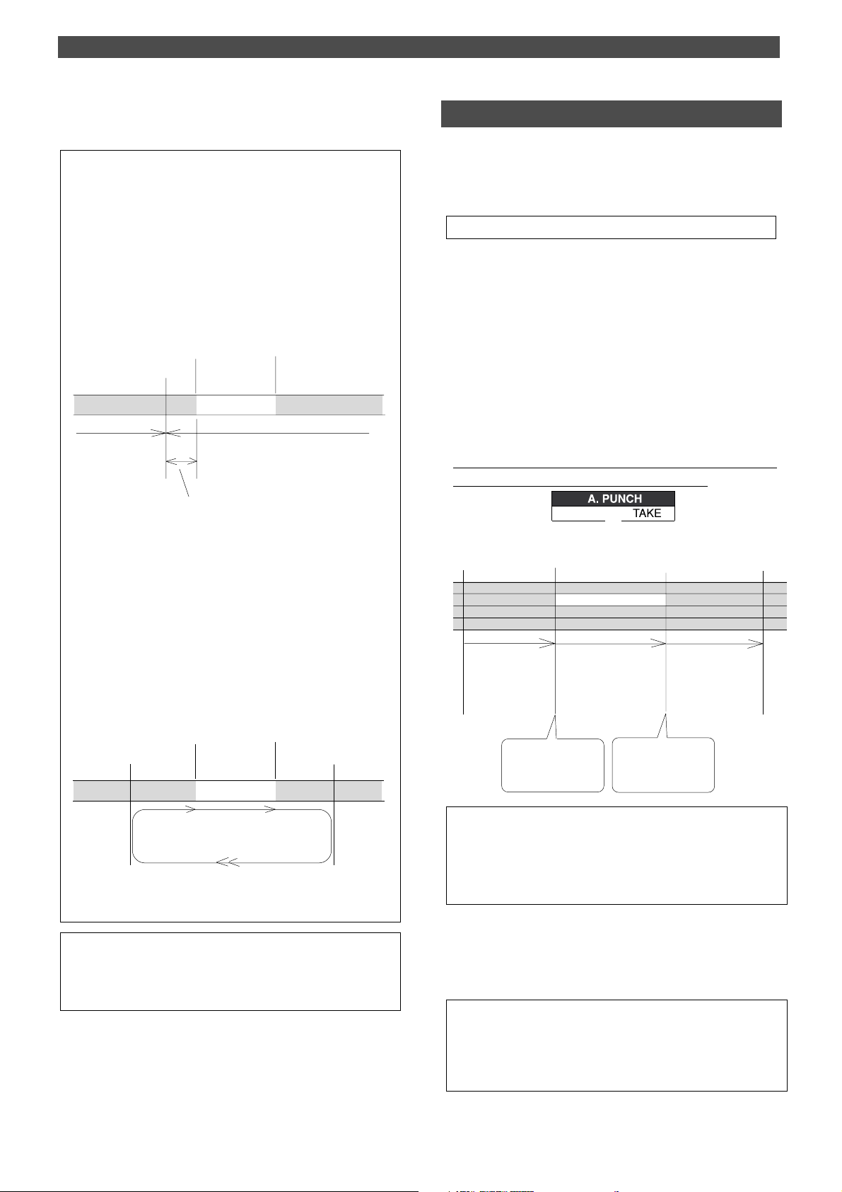
Special Application (Punch In/Out Recording)
5.When you are satisfied with your rehearsal, press the STOP
button.
<Hint 1>
Locating a point slightly before the Auto Punch In point
To locate the playback start point for rehearsal, press the AUTO
PUNCH IN key , then press the LOCATE key .
The FD-4 displays the time (position) stored in the AUTO PUNCH
IN key , and locates the point and stops.
Press the REWIND button to go backward. If you have set the preroll
time as described on page 85, you can locate a point that precedes
the Auto Punch In point by the specified preroll value. For more
information, see “Setting a preroll time” on page 85.
Auto Punch In point
Stop here.
Locate
The FD-4 stops at a point that precedes the Auto
Punch In point by the specified preroll time. (0~10
seconds)
Auto Punch Out point
Locate
Auto Punch In/Out T ake
After you are satisfied with your rehearsal, you can proceed to an actual take of Auto Punch In/Out. You can undo
or redo Auto Punch In/Out recording if you change your
mind.
• The control panel settings are the same as those for rehearsal.
1.Locate a point slightly before the Auto Punch In point.
2.Confirm that Auto Punch mode is turned on.
If it is not on, press the RECORD button while holding
down the SHIFT key.
3.Press the RECORD TRACK select key [3/L] to set track 3 to
READY .
4.Press the RECORD button while holding down the PLAY
button.
The flashing [RHSL] on the display changes to an
illuminated [TAKE], and recording starts.
The FD-4 operates as follows. To record, hold down the
PLAY button and press the RECORD button.
<Hint 2>
Quick and easy operation for repeated rehearsal
Using the Auto Return function and the Auto Play function enables
you to rehearse repeatedly.
As shown below, set the AUTO RTN START and END points for
Auto Return and Auto Play. In this way, you can repeat rehearsal
easily , while checking the recording level and concentrating on your
performance.
Refer to page 63 for more information on setting the AUTO RTN
ST ART/END points.
Auto Punch In point
AUTO RTN ST ART point
Rehearsal area
Playback starts from the AUTO RTN START point,
and you can rehearse Auto Punch In/Out.
When the AUTO RTN END point is reached, the FD-4 locates
the AUTO RTN START point.
Auto Punch Out point
AUTO RTN END point
<Note>
If the FD-4 display [Over] when you turn on Auto Punch mode, the
disk does not have enough free space for Auto Punch In/Out. You
need to erase part of the Program data, then try again.
Playback
start point
Track 4
Track 3
Track 2
Track 1
All tracks are in playback
monitoring mode.
Auto Punch In point
(Rehearsal in)
This part is changed.
Only track 3 is in input
monitoring mode, and data
will be recorded.
The Record button LED
flashes in this area.
The FD-4 punches in
automatically at the
Punch In point.
Auto Punch Out point
(Rehearsal out)
All tracks are in playback
monitoring mode.
The FD-4 punches out
automatically at the
Punch Out point.
Playback
end point
• The LED of the REC RACK select key 3/L remains steadily lit
between the Punch In and Out points. Otherwise, it flashes.
• When the Auto Punch Out point is passed, the FD-4 cancels
Auto Punch mode automatically, and nothing appears in the
A. PUNCH display area.
5.Hold down the PLAY button and press the RECORD button.
6.When you finish recording, press the STOP button.
7.Play track 3 to check the result of the Auto Punch In/Out
operation.
<Caution after Punch Out>
At “T ake” of punch out, the punch-in recording track will not immediately enter the repro monitor mode from the input monitor mode
enter the repro monitor mode about two seconds after mute playback. This is a functional feature of FD-4 and not a malfunction.
45
Page 46
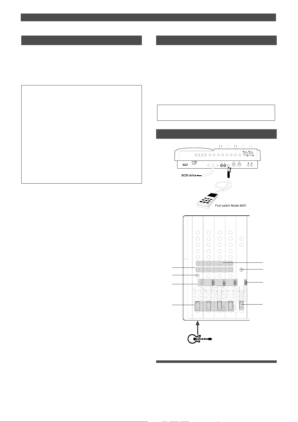
Special Application (Punch In/Out Recording)
Undo/Redo Auto Punch In/Out recording
You can undo or redo Auto Punch In/Out recording.
Press the UNDO/REDO key after recording is complete to
restore the conditions that existed prior to the recording.
Press the UNDO/REDO key again to restore the conditions
that existed after the recording. Follow the notes below:
<Note-1>
The Undo/Redo function is effective only when the FD-4 is stopped.
<Note-2>
The Undo/Redo is not effective if you perform one of the following
operations after you finish recording:
• When a new recording is made.
• While a new editing is executed (such as Copy & Paste, Move &
Paste, or Erase).
• When in the AUTO PUNCH ON mode, when the AUTO PUNCH
IN point is passed in the PLA Y (or RECORD) mode.
• When the power is momentarily switched off.
• When the program is changed.
• When the disk is ejected.
Manual Punch In/Out
This section explains how to perform Manual Punch In/
Out using a foot switch (optional Model 8051).
You do not need to specify the Punch In/Out points.
Instead, you press the foot switch at the Punch In/Out point.
Manual Punch In/Out also offers rehearsal and actual takes.
You can repeat rehearsal until you are ready.
As an example, replace a part of the recorded guitar solo on
track 3.
• Initialize the FD-4.
• Select a desired Program for Punch In/Out.
Preparation
INPUT 3
AUX RTN 1
R MON OUT L R MIX OUT L
POWER
AUX RTN 2
R MONO/L2 AUX SEND 1 4 INSERT 3
DATA MIDI
SCSI
R MONO/L
DATA
PUNCH
OUTIN
IN/OUT
INPUT 4
RECORDER IN
MIDI
R
LIN
OUT
2
EQ
EQ
3
3
3
3
3
3
3
3
1
Connecting the instrument and a foot switch
1.Connect the guitar to input jack 1.
2.Connect an optional foot switch (Model 8051) to the PUNCH
IN/OUT jack on the rear panel.
46
Page 47
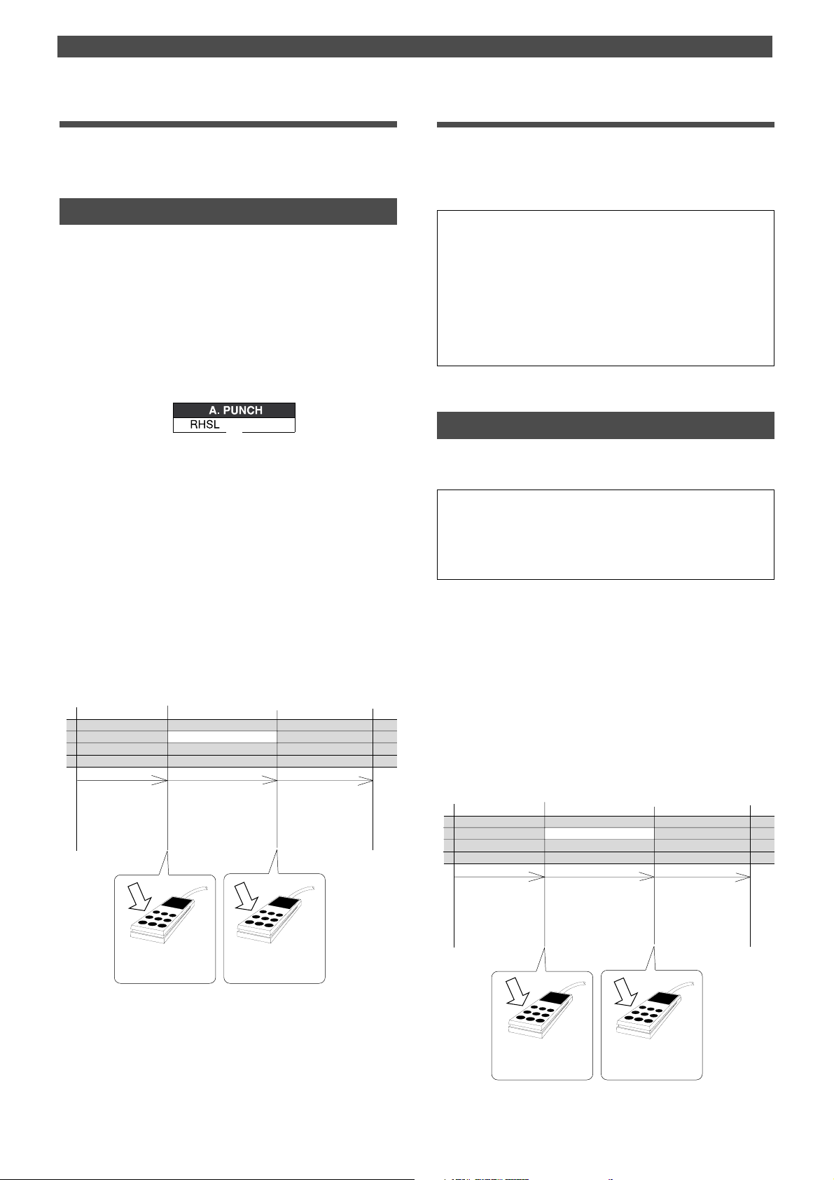
Special Application (Punch In/Out Recording)
Setting the mixer section.
3.Set up the mixer control section as explained in the “Auto
Punch In/Out” section.
Rehearsing Punch In/Out recording
In Rehearsal mode, the READY track enters input monitoring mode between the Punch In and Out points (the points
at which you press the foot switch), and the sound is not
recorded. You can practice the Punch In/Out operation repeatedly before you proceed to actual recording.
1.Press the foot switch while holding down the STOP button.
The FD-4 displays [Rehsl On] for a second and enters
Rehearsal mode.
[RHSL] flashes in the A.PUNCH display area.
2.Press the RECORD TRACK select key [3/L] to set track 3 to
READY .
3.Press the PLAY button to play back from a point slightly
before the Punch In point.
4. Play the guitar accompanying the playback of tracks 1 and 2.
Follow the instructions in the “Auto Punch In/Out”
section to adjust the recording level and the monitor level.
5.Press the foot switch once at the desired Punch In point,
then press the foot switch again at the desired Punch Out
point.
The FD-4 operates as follows. You will hear your
performance between the Punch In/Out points.
Otherwise, you will hear the previously-recorded guitar.
Playback
start point
Track 4
Track 3
Track 2
Track 1
All tracks are in playback
monitoring mode.
Punch In point
(Rehearsal in)
This part is changed.
Only track 3 is in input
monitoring mode.
The sound is not recorded at
The Record button LED
flashes in this area.
this time.
Punch Out point
(Rehearsal out)
All tracks are in playback
monitoring mode.
Playback
end point
Cancelling Rehearsal mode
1.While holding down the STOP button, press the foot switch.
[Rehsl Off] appears for a second, the flashing [RHSL]
indicator in the A. PUNCH display area disappears, and
Rehearsal mode is cancelled.
<Hint>
To rehearse repeatedly, set the AUTO RTN START point slightly
before the Punch In point, and the AUTO RTN END point slightly
before the Punch Out point.
This will help you concentrate on your performance or check the
recording level easily (especially since Manual Punch In/Out involves operating the foot switch operation as well as the FD-4).
(See <Hint-2> in the “Rehearsing Auto Punch In/Out recording” for
more information.)
Manual Punch In/Out take
You can proceed to record if you are satisfied with the recording level, foot switch timing, and rehearsal.
<Note>
You cannot record a second take during the Manual Punch In/Out
operation without stopping the FD-4. That is, the FD-4 will continue
playing after you finish recording a take, but you cannot record another take by pressing the foot switch.
1.Confirm that Rehearsal mode is cancelled, and start playing
the FD-4 from a point slightly before the desired Punch In
point.
2. Play the guitar, accompanying the playback of tracks 1 and 2.
3.Press the foot switch at the desired Punch In point. Press
the foot switch again at the desired Punch Out point.
The FD-4 will operate as follows. The FD-4 enters
recording mode at the Punch In point, and cancels
recording mode at the Punch Out point.
Playback
start point
Track 4
Track 3
Track 2
Track 1
Punch In point
(Take in)
Punch Out point
This part is changed.
(Take out)
Playback
end point
Press the foot switch at
the Punch In point.
Press the foot switch at
the Punch Out point.
6.When you finish rehearsing, press the STOP button.
If you are still unsatisfied, repeat steps 3–5.
All tracks are in playback
monitoring mode.
Press the foot switch at
the Punch In point.
Only track 3 is in input
monitoring mode, and data
will be recorded.
Press the foot switch at
the Punch Out point.
All tracks are in playback
monitoring mode.
47
Page 48

Special Application (Punch In/Out Recording)
4.Press the STOP button.
5.Play track 3 and check the result of Punch In/Out.
<Caution after Punch Out>
At “T ake” of punch out, the punch-in recording track will not immediately enter the repro monitor mode from the input monitor mode
enter the repro monitor mode about two seconds after mute playback. This is a functional feature of FD-4 and not a malfunction.
<Hint>
You can use the PLA Y button and the RECORD button, instead of
using the foot switch. Follow the steps below.
This method also does not allow you to record another take unless you stop the FD-4 first.
Procedure:
1
.Press the PLAY button to start playback from a point slightly
before the Punch In point.
2
.Press the RECORD button while holding down the PLAY
button at the desired Punch In point. (Punch In recording starts.)
3
.Press the PLAY button at the desired Punch Out point.
(Recording is punched out.)
• If you press only the RECORD button in both steps 2 and 3,
you can rehearse Punch In/Out.
Undo/Redo Manual Punch In/Out recording
You can undo or redo Manual Punch In/Out recording.
Press the UNDO/REDO key after recording is complete to
restore the conditions that existed prior to the recording.
Press the UNDO/REDO key again to restore the conditions
that existed after the recording. Follow the notes below:
<Note-1>
The Undo/Redo function is effective only when the FD-4 is stopped.
<Note-2>
The Undo/Redo is ineffective if you perform one of the following
operations after you finish recording.
• When a new recording is made.
• While a new editing is executed (such as Copy & Paste, Move
& Paste, or Erase).
• When in the AUTO PUNCH ON mode, when the AUT O PUNCH
IN point is passed in the PLAY (or RECORD) mode.
• When the power is momentarily switched off.
• When the program is changed.
• When the disk is ejected.
48
Page 49
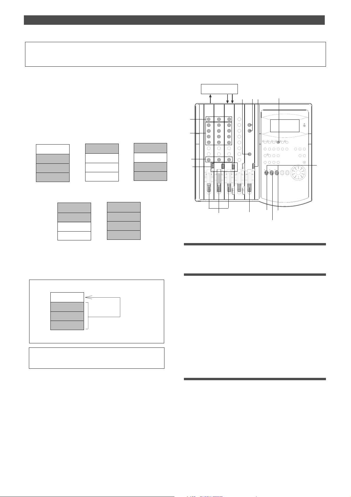
Ping-Pong Recording
Ping-pong recording is a recording process in which you
mix the playback sound of multiple tracks and record the
mix on an empty track. Ping-pong recording enables you to
use previously-recorded tracks in a new recording.
In this way, you can overdub more sound sources using a
limited number of tracks.
<Example of ping-pong recording>
1. Record A, B and
C on tracks 1~3.
TRK 4
TRK 3
TRK 2
TRK 1
Sound source C
Sound source B
Sound source A
2. Ping pong record
Sound source A,B,C
TRK 4
TRK 3
TRK 2
TRK 1
on track 4.
3. Record D and E
on tracks 1 and 2.
Sound source A,B,C
TRK 4
TRK 3
TRK 2
TRK 1
Sound source E
Sound source D
11
10
3
Special Application (Ping Pong Recording)
Effect Unit
1
11
12
4
EQ
EQ
2
5
13
4. Ping pong record
D and E on track 3.
TRK 4
Sound source A,B,C
TRK 3
Sound source D,E
TRK 2
TRK 1
Result: a total of 7 recorded parts A~D.
5. Record F and G
TRK 4
Sound source A,B,C
TRK 3
Sound source D,E
TRK 2
TRK 1
tracks 1 and 2.
Sound source G
Sound source F
In this example session, ping-pong record the sound sources
recorded on tracks 1–3 to track 4. At this time, apply effects
to tracks 1–3 signals.
TRK 4
TRK 3
Sound source C
Sound source B
TRK 2
TRK 1
Sound source A
• Initialize the FD-4.
• If multiple Programs exist, select the desired Program first.
Ping pong recording
(Original sound and
effected sound)
9
6
8
7
14
Connecting effect units
1.Connect effect units to Aux send/return.
Setting the switch and knob
2.Set the channels 1–3 INPUT SEL switches to TRK.
Tracks 1–3 playback signals are routed to the
corresponding input channel faders.
3.Turn the channels 1–3 PAN knobs all the way to [R].
4.Set the monitor SELECTOR to L/R.
You can monitor the stereo bus L/R output signals.
5.Press the RECORD TRACK select key 4/R to set track 4 to
READY .
6.Raise the master fader L/R to 7–8.
Adjusting the recording level/rehearsal
7.Press the RECORD button to set track 4 to input monitoring
mode.
8.Start playing the Program from the beginning.
9.Use the channels 1–3 input faders to adjust the track output
levels.
The level meters 4 and R respond. Tracks 1–3 level meters
indicate the corresponding track output levels.
10. Adjust the channel equalizers, if necessary.
49
Page 50

Special Application (Ping Pong Recording)
11.T urn the AUX knob of the channel signal to which you wish
to apply effects toward AUX 1. Use the AUX RTN 1 knob to
adjust the return signal level.
At this time, make sure that the [OL] section of level meters
4 and R do not light up continuously.
12. Raise the MASTER knob in the monitor section gradually
to listen to the mix to be ping-pong recorded.
When you finish adjusting the level, effects, and balance,
stop the recorder section and locate the top of the
Program.
Performing ping-pong recording
13. Hold down the RECORD button and press the PLA Y button
to start recording.
Quitting ping-pong recording
14. Stop the recorder section, and initialize the FD-4.
Checking the ping-pong recording results
1.Set the monitor SELECTOR to MON.
Now you have applied effects to tracks 1–3, mixed them,
and recorded to track 4.
After this ping-pong recording, you can erase data on tracks
1–3 and overdub other sound sources.
In this way, you can record numerous sound sources with a
limited number of tracks.
You can also use the Additional tracks of the FD-4 for pingpong recording (excluding disks formatted in Mastering
mode 2).
Refer to the next page for more information on ping-pong
recording on the Additional tracks.
2.Play the Program from the beginning.
3.Turn the channel 4 MON knob toward [TRK] and turn the
MASTER knob in the monitor section gradually to audition
the sound on track 4.
If the result is not satisfactory, you can undo/redo the
recording as described below.
Undo/Redo ping-pong recording
You can undo or redo ping-pong recording.
• Press the UNDO/REDO key after ping-pong recording is complete to
restore the conditions that existed prior to the recording.
• Press the UNDO/REDO key again to restore the conditions that
existed after the recording.
When you perform Undo or Redo, [Undo !] or [Redo !], then
[COMPLETED !] appear, and the FD-4 displays the previous
Time Base.
<Note>
The Undo/Redo function is effective only when the FD-4 is stopped.
The Undo/Redo is ineffective if you perform one of the following
operations after you finish ping-pong recording.
1. When a new recording is made.
2. When a new editing is executed (such as Copy & Paste, Move &
Paste, Erase).
3. While in the AUTO PUNCH ON mode, when the AUTO PUNCH
IN point is passed in the PLAY (or RECORD) mode.
4. When the power is momentarily switched off.
5. When the program is changed.
6. When the disk is ejected.
50
Page 51

Special Application (Ping Pong Recording)
Ping-pong Recording to Additional Tracks
This chapter explains how to perform ping-pong recording
using Additional tracks L and R.
In this example session, we ping-pong record tracks 1–4 to
the Additional tracks.
ADD. TRK R
ADD. TRK L
TRK 4
TRK 3
TRK 2
TRK 1
Sound source D
Sound source C
Sound source B
Sound source A
Ping pong recording
(Original sound and
effected sound)
<Notes>
*
This function is available only when you are using a disk
formatted in Normal mode or Mastering mode 1.
You cannot use a disk formatted in Mastering mode 2, which
allows for normal ping-pong recording.
*
You cannot play back data recorded on Additional tracks. T o play
back the data, move it to Real tracks 1–2 or 3–4.
• Initialize the FD-4 before you start the operation.
• If multiple Programs exist, select the desired Program first.
At this time, check the recording level of the Additional
tracks via the level meters L and R. Adjust the input
channel faders so that the [OL] section of the level meters
L and R will not light up continuously.
8.Adjust the channel equalizers, if necessary.
9.Turn the AUX knob of the channel signal to which you wish
to apply effects toward AUX 1. Use the AUX R TN 1 knob to
adjust the return signal level.
At this time, make sure that the [OL] section of level meters
4 and R do not light up continuously.
10. Raise the MASTER knob in the monitor section gradually
to listen to the mix sound to be ping-pong recorded.
When you finish adjusting the level, effects, and balance,
stop the recorder section and locate the top of the
Program.
Performing ping-pong recording
1 1. Holding down the RECORD button and press the PLA Y
button to start recording.
Quitting ping-pong recording
12. Stop the recorder section, and initialize the FD-4.
Checking the result of ping-pong recording
Connecting effect units
1.Connect effect units to Aux sends/returns.
Setting the switch and knob
1.Set the channel 1–4 INPUT SEL switches to TRK.
Tracks 1–4 playback signals are routed to the
corresponding input channel faders.
2.Turn the channel 1–4 PAN knobs all the way [L] or [R]
depending on the sound sources so that they will be
recorded to Additional tracks L and R.
3.Set the monitor SELECTOR to L/R.
You can monitor the stereo bus L/R output signals.
4.Press the RECORD TRACK select keys L and R.
5.Raise the master fader L/R to 7–8.
Adjusting the recording level/rehearsal
6.Start playing the Program from the beginning.
Since Additional tracks cannot be set to input
monitoring mode, you do not have to press the RECORD
button at this time.
7.Use the channel 1–4 input faders to adjust the track output
levels.
Because any sound that has been ping ponged onto the
additional track cannot be checked directly, the additional
track and a real track must be temporarily exchanged.
1.Use the Track Exchange function to swap data between the
Additional and Real tracks.
• See “Track Exchange” on page 60 for more information on moving
data between tracks.
2.Set the monitor SELECTOR to MON.
3.Play the Program from the beginning.
4.Turn the MON knob of the channel (to which you moved the
data) toward [TRK] and turn the MASTER knob in the
monitor section gradually to audition the sound.
After exchanging the additional track with the real track and checking it. UNDO/REDO can be executed in the same way as with
the previous “ping pong recording” if you are not satisfied after
checking it.
If UNDO is executed after checking the sound, it can be returned to the state prior to executing ping pong.
If REDO is executed after execution of UNDO, it can be returned to the state prior to the second execution of UNDO (The
state upon moving to the real track).
51
Page 52
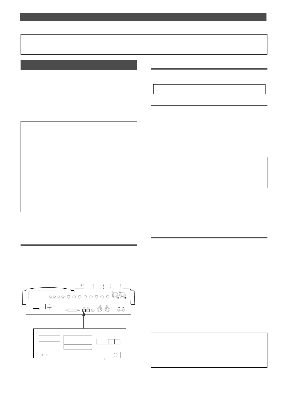
Special Application (Digital Recording)
Digital Recording
Digital recording from an external digital device
This chapter describes how to digitally record data from a
connected digital device (CD, MD, DAT, etc.) to tracks on
the FD-4.
Selecting a Program to record
1.If multiple Programs exist, first select the desired Program
using the Program Change function.
• See page 36 for more information on Program Change.
Use the “Setting digital input tracks” menu in SETUP mode
to assign incoming digital signals (L, R) to a track.
Setting a recording track
The currently-selected Program will be used for digital recording. The digital input track assignment is shared by all
existing Programs.
<Note>
The “Setting digital input tracks” menu has Real tracks 1–4 and
Additional tracks L (indicated as 5) and R (indicated as 6) as options. However, you can record digital data to Additional tracks if the
disk’s recording mode is Normal or Mastering 1. If the disk is format-
2. Select the desired track using the “Setting digital input tracks”
menu in SETUP mode.
When a track is assigned and a correct digital signal is
input, the FD-4 displays [DIGITAL] on the display.
If incoming digital signal is abnormal, the [DIGITAL]
indicator flashes. Refer to “Setting digital input tracks” in
the “Changing the Initial Settings (SETUP Mode)” chapter
on page 91.
ted in Mastering mode 2, you cannot record data on the Additional
tracks. If you try to record data on the Additional tracks using the
disk in Mastering mode 2, an error message [Can’t Rec!] appears
and the operation is ignored.
<Caution>
Do not connect or disconnect an optical cable to or from the DA TA IN
jack of the FD-4 while a track is assigned as digital input. Otherwise,
noise may be induced to the FD-4, affecting the connected digital
<Note>
device.
When you are using a disk in Normal mode, input a digital source
with a sampling rate of 32kHz. When you are using a disk in Mastering mode 1 or Mastering mode 2, input a digital source with a
sampling rate of 44.1kHz.
When you finish setting the parameters in SETUP mode,
be sure to press the EXIT/NO key or the STOP key to exit
SETUP mode.
Connecting an external digital device
1.Connect the DAT A IN jack of the FD-4 with the OPTICAL OUT
jack of an external digital device using an optical cable.
If the digital device has only the COAXIAL (RCA pin) jack
as a digital output, use a Fostex COP-1 (an optional
optical/coaxial converter).
INPUT 3
AUX RTN 2
R MON OUT L
R ST OUT L
2 AUX SEND 1
POWER
SCSI
R MONO/L
DATA
DATA
OUTIN
DATA IN
OPTICAL OUT
AUX RTN 1
R MONO/L
PUNCH
IN/OUT
MIDI
4 INSERT 3
INPUT 4
RECORDER IN
MIDI
R
OUT
LIN
3.Press the RECORD RACK select key of the assigned track
to set the track to READY .
Starting and quitting recording
1.Locate the top of the Program.
2.Make sure that [DIGITAL] lights up on the display. Hold down
the RECORD button and press the PLA Y button to start
recording on the FD-4.
3.Start playback on the external digital device.
You do not need to adjust the recording level during
digital recording. If you are recording data on one of tracks
1–4, set the monitor SELECTOR to [MON] so that you can
monitor the recorded signal via the MON mix section of
the channel that corresponds to the track.
You cannot monitor the signal while you are recording
data on an Additional track.
4.When recording is complete, stop the FD-4 and the digital
device.
<Note>
While a track is assigned for digital input, you cannot use the same
track for analog recording via the corresponding input jack. When
you finish digital recording, set the “Setting digital input tracks” menu
to [L-, r-] (no assign).
52
Page 53

Special Application (Digital Recording)
Digital recording to an external device
This section explains how to record digital data from the
FD-4 to an external digital device, such as an MD, DAT, or
CD-R.
You can select any pair combination from Real tracks 1–4
and S-T (STEREO OUT L/R output in the mixer section) for
digital output L and R.
The current Program is used for digital recording.
The digital output track assignment is shared by all existing Programs.
<Note>
When you are using a disk in Normal mode, digital signal will be
output with a sampling rate of 32kHz. When you are using a disk in
Mastering mode 1 or Mastering mode 2, digital signal will be output
with a sampling rate of 44.1kHz.
<Note>
You cannot output data on the Additional tracks as it is. Y ou need to
move the data to the Real tracks using the T rack Exchange function.
Connecting an external digital device
which enables you to perform digital mixdown as
described later.
Refer to “Setting digital output tracks” in the “Changing
the Initial Settings (SETUP Mode)” chapter on page 92 for
more information on setting a digital output track.
<Note>
You cannot assign the same track to L and R.
When you finish setting the parameters in SETUP mode, be sure to
press the EXIT/NO key or the STOP key to exit SETUP mode.
Starting and quitting recording
1.Locate the top of the Program.
2.Start recording on the external digital device.
3.Press the PLAY button on the FD-4 to start playback.
Digital data is output from the selected track and recorded
on the external digital device.
4.When recording is complete, stop the FD-4 and the digital
device.
1.Connect the DAT A OUT jack of the FD-4 with the OPTICAL
IN jack of an external digital device using an optical cable.
If the digital device has only the COAXIAL (RCA pin) jack
as a digital output, use an optional COP-1 (optical coaxial converter).
AUX RTN 2
R MON OUT L
R ST OUT L
2 AUX SEND 1
POWER
SCSI
R MONO/L
DATA
DATA
OUTIN
AUX RTN 1
R MONO/L
PUNCH
MIDI
IN/OUT
DATA OUT
OPTICAL IN
4 INSERT 3
INPUT 4
RECORDER IN
MIDI
R
OUT
LIN
INPUT 3
Selecting a Program to record
1.If multiple Programs exist, first select the desired Program
using the Program Change function.
Setting a digital output track
2.Select the desired track using the “Setting digital output
tracks” menu in SETUP mode.
If you assign [L- , r- ] (STEREO OUT L and R), the
STEREO OUT L/R output of the FD-4 will have priority,
53
Page 54
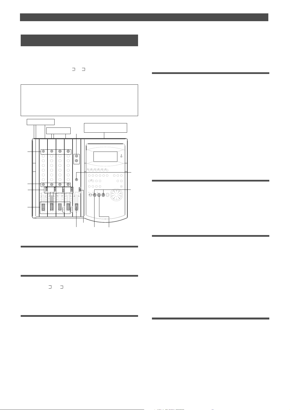
Special Application (Digital Recording)
Digital mixdown
As described in the previous section, you may mix down
digital signals from tracks 1–4 to an external digital device
using the procedure described in the basic mixdown section, in which you set [L- , r- ] for digital output tracks.
Refer to the “Basic Multitrack Recording” chapter for information on how to connect effect units.
<Note>
When you are using a disk in Normal mode, digital signal will be
output with a sampling rate of 32kHz. When you are using a disk in
Mastering mode 1 or Mastering mode 2, digital signal will be output
with a sampling rate of 44.1kHz.
10
4, 8
5, 12
3
14
DAT
7
11
6, 13
9
2
1
7
Effect unit 1
Effect unit 2
EQ
EQ
and the vocal to right. Follow your intuition.
3.Set the SELECTOR in the monitor section to [L/R].
4.Raise the master fader L/R to [7–8].
Setting the output level and the master recorder
5.Set the master recorder to recording standby mode.
You should be able to check the recording level.
6.Press the PLAY button to play back the Program from the
beginning.
7.Raise the channel faders and gradually turn the MASTER
knob in the monitor section to monitor the sound.
Use the channel faders to adjust the track playback levels
while monitoring the sound. At this time, check the level
meters L and R and adjust the faders so that the [OL]
section of the meter will not light up with the maximum
level.
8.When you obtain a satisfactory balance, use the master
fader L/R to adjust the final output level.
Also adjust the input level on the master recorder.
Settings for the effect units
9.Turn the AUX knob for the channel signal to which you wish
to apply effects toward [AUX 1] or [AUX 2].
Turn the knob toward [AUX 1] to apply reverberation;
turn it toward [AUX 2] to apply chorus.
10. Use the AUX RTN 1 and AUX RTN 2 knobs to adjust the
input level from the effect units to the stereo bus L/R.
Mixdown
Connecting an external digital device
1.Connect the DAT A OUT jack of the FD-4 with the OPTICAL
IN jack of an external digital device using an optical cable.
Assigning output tracks
2.Use the “Setting digital output tracks” menu in SETUP mode
to select [L- , R- ] as output tracks.
Refer to “Setting digital output tracks” of the “Changing
the Initial Settings (SETUP Mode)” chapter.
Setting the switch and knob on the FD-4
1.Set the INPUT SEL switches of channels 1–4 to [TRK].
In this way, the output from recorded tracks 1–4 will be
routed to the corresponding input channel faders for
equalization and effect processing.
2.Set the channel PAN knobs accordingly.
There is no rule on the position of the PAN knobs.
The settings will vary depending on the type of
instrument you recorded or the feel of your song.
You can, for example, pan a given instrument to the left
1 1. Hold down the STOP button and press the REWIND button
to locate the beginning of the Program.
12. Start recording on the master recorder.
Adjust the input level on the master recorder so that its
level meters indicate almost the same level as the FD-4’s
level meters L/R.
13. Press the FD-4’s PLA Y button to play the Program from the
beginning.
Operate the master faders L/R to fade the mixdown sound
in and out.
Quitting mixdown
14. Stop the master recorder and the FD-4.
54
Page 55
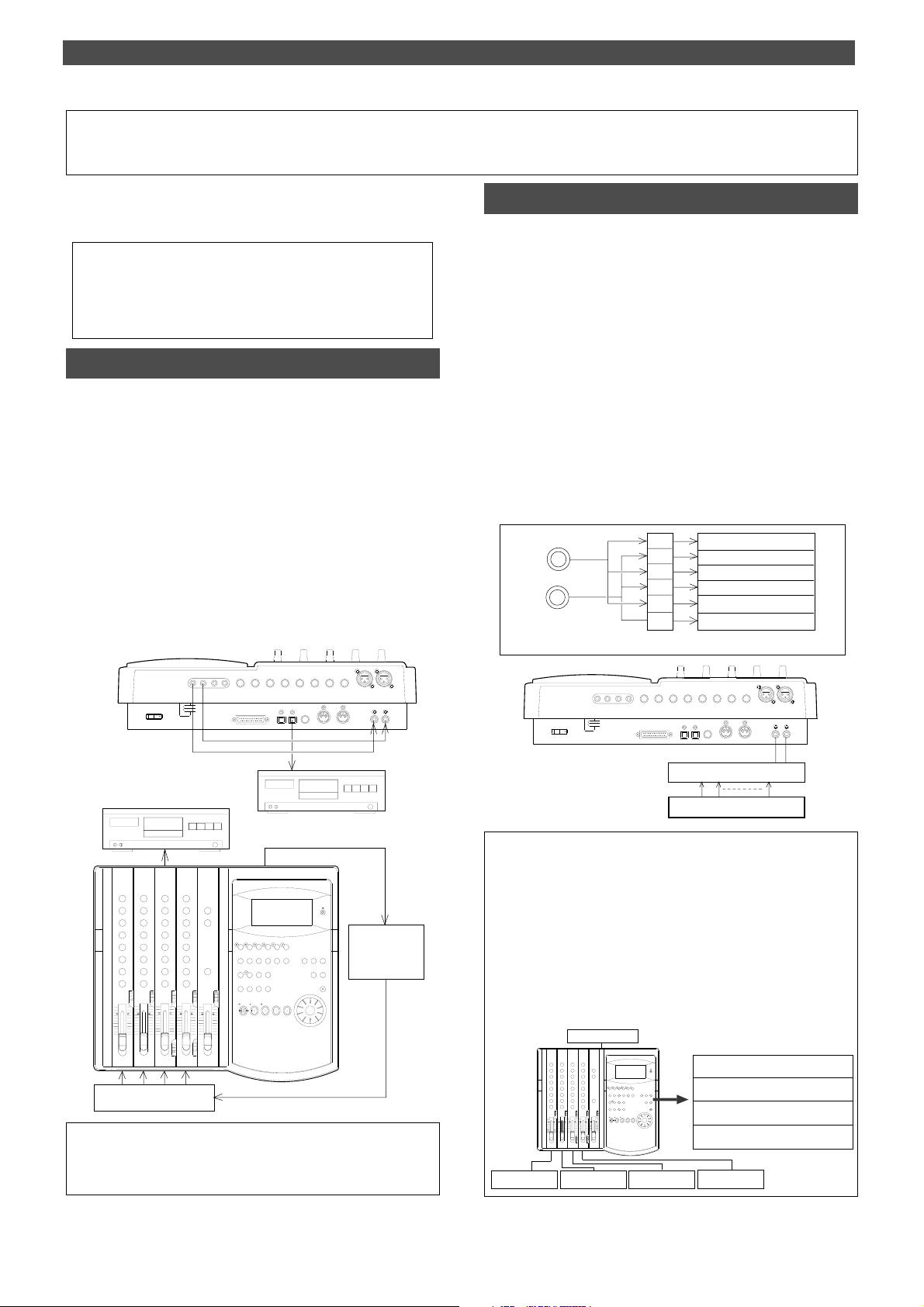
Å@Special Application (How to use the RECORDER IN jack)
EQ
EQ
How to use the RECORDER IN jack
The following explains the various functions of the RECORDER IN jack.
There are two ways to use the RECORDER IN jack.
1. Synchronizing an external MIDI sound source with the performances
recorded on tracks 1 ~ 4 and digitally mixing down a maximum of
eight channels of sound sources.
2. Directly recording external sound sources without routing them
through a mixer.
Eight channels of digital mixdown
In this method, the RECORDER IN (L, R) jacks of the FD-4 are
directly connected to the MON OUT (L, R) jacks and the monitor SELECTOR switched to [L/R+MON]. Then, the monitor bus
L, R signal and the stereo bus L, R signals are both simultaneously output from MON OUT L, R and input to RECORDER IN
L, R. As shown in the drawing below, an external MIDI sound
source is input to INPUT jacks 1~4, and then each channel
INPUT fader is raised, and performances recorded on tracks
1~4 are applied to each channel MON mix section, and played
back using MIDI sync of both performances. With this method,
a maximum of eight channels (Tracks 1~4 and MIDI sound) of
sound sources are mixed and sent to the RECORDER IN L, R
from MON OUT L, R, and digitally mixed down in an outboard
digital device (DAT).
INPUT 3
AUX RTN 2
R MON OUT L
R ST OUT L
2 AUX SEND 1
POWER
SCSI
R MONO/L
AUX RTN 1
R MONO/L
DATA
DATA
PUNCH
OUTIN
IN/OUT
INPUT 4
4 INSERT 3
RECORDER IN
MIDI
MIDI
R
LIN
OUT
Direct recording of an external sound source
Here, an external sound source is directly input to the RECORDER
IN jack of the FD-4 and recorded in the recorder section without
passing through a mixer.
In this case, if an external input is connected to L and R of the
RECORDER IN jack, it will not be possible to record through the
mixer section.
In the illustration below, the signal input to L of RECORDER IN is
sent to tracks 1, 3 and L, and the signal input to R of RECORDER IN
is sent to tracks 2, 4 and R. Any two tracks are selected for recording. If the connection is made from the mixer group out, using a
patch bay will faciliate connections from the front panel as shown
in drawing below. The recording level is adjusted at the external
equipment side and, by setting the monitor section SELECTOR to
[MON] at the FD-4 side, sound can be monitored using the MON
mix section of the channel corresponding to each track. Recording
onto the additional track is possible only in the normal mode and
mastering mode 1.
RECORDER IN
L
R
R MON OUT L
POWER
1/L
2/R
3/L
4/R
L
R
REC SEL switch
R ST OUT L
2 AUX SEND 1
SCSI
AUX RTN 2
R MONO/L
AUX RTN 1
R MONO/L
DATA
DATA
PUNCH
OUTIN
IN/OUT
Real track 1
Real track 2
Real track 3
Real track 4
Additional track L
Additional track R
Recorder section
INPUT 4
4 INSERT 3
RECORDER IN
MIDI
MIDI
R
OUT
INPUT 3
LIN
DAT
External mixer etc.
Patch bay
DAT
<More applications for using RECORDER IN>
If an external sound source is connected to both L and R of RECORDER IN,
recording cannot be done via the INPUT fader. If only one jack (L or R) is con-
EQ
EQ
nected, the track corresponding to the jack not connected can be recorded simultaneously via the INPUT fader. For example, if sound source E is connected to
only L of RECORDER IN, another sound source applied via the INPUT fader can
MIDI
Sequencer
be recorded on any one of tracks, 2, 4, R corresponding to R of RECORDER IN to
which nothing is connected. In other words, because the FD-4 can simultaneously
record two tracks, a sound source from RECORDER IN can be recorded on one
track and sound source routed via the INPUT fader can be simultaneously recorded on the other track.
Sound source E
MIDI sound sources
For details on digital mixdown by synchronizing with a MIDI sound
Track 2 (sound source E)
Track 1 (sound sources A, B, C and D)
source, please refer to “MIDI clock sync system” of “MIDI synchronization” on page 71.
Sound source A
Sound source B Sound source C
Sound source D
55
Page 56
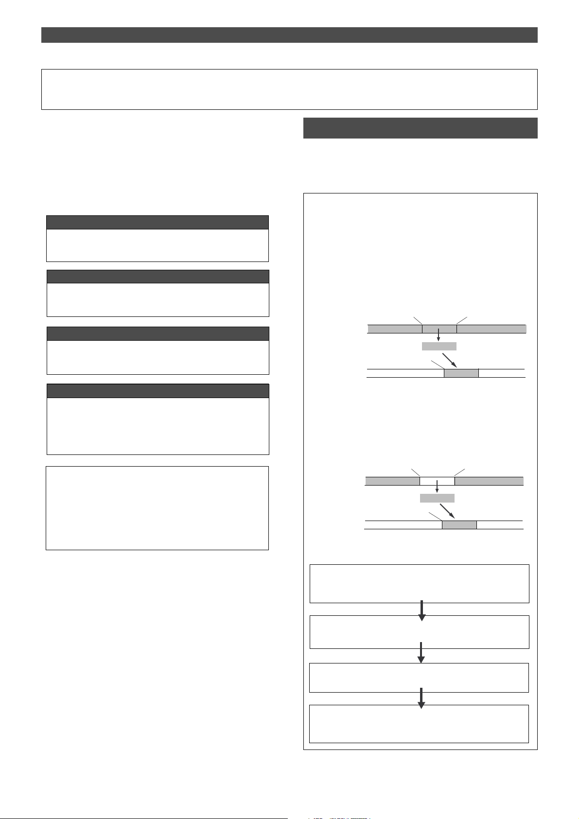
Editing Tracks
Editing Tracks
The FD-4 features speedy, non-linear, non-destructive editing of independent audio tracks and uses a Zip, EZ or MO
disk as the recording media.
The following edit functions enable you to edit tracks. Press
the EDIT key on the control panel to access the edit menu.
<Edit functions>
Copy & Paste
You can copy a specific range of data from a specific track and
paste it to the same or a different track.
Move & Paste
You can move a specific range of data from a specific track and
paste it to the same or a different track.
Erase
You can erase a specific range of data from a specific track or
from all tracks.
Track Exchange
You can swap data between tracks.
Monaural track data can be swapped between Real tracks 1–4
and Additional tracks L/R. Two-track data can be swapped between Real tracks 1–2, 3–4, and Additional tracks L–R.
<Note>
These edit functions are available for the currently-selected Program. If the disk contains multiple Programs, you need to select
the desired Program first to perform the track edit operation.
Do not select another Program until you finish the edit operation.
Otherwise, you may lose or incorrectly edit another Program.
Copy & Paste and Move & Paste
Copy & Paste and Move & Paste might seem like the same
function. However, they are different, as shown in the diagram. Remember this difference when you start using these
functions.
• Copy & Paste
Using the Copy & Paste function enables you to copy a specific range of
data from a specific track to the clipboard as shown below (this is called
[Copy Clip] operation on the FD-4), then paste the data at a specific
point in a specific track. The number of copy source tracks and the
number of destination tracks are the same. That is, if you copy mono
track data, you can paste it to a mono track. If you copy adjacent odd/
even tracks (e.g., track 1 and track 2), you can paste it to adjacent odd/
even tracks. The data on the clipboard remains as it is. You can paste it
as many times as you wish.
Copy source track
Paste destination track
CLIPBOARD IN point
AUTO PUNCH IN point
• Move & Paste
Move & Paste is almost the same as Copy & Paste. It allows you to
move a specific range of data from a specific track to the clipboard (this
is called [Move Clip] on the FD-4), and paste it to a destination track.
The difference from Copy & Paste is that the data on the source track
and the clipboard will be erased when you paste the data to the destination.
Move source track
Paste destination track
Follow the steps below to perform the Copy & Paste or Move & Paste
operation.
Store the copy (move) start point (CLIPBOARD IN point), end
point (CLIPBOARD OUT point), and the paste start point (AUTO
PUNCH IN point).
CLIPBOARD IN point
AUTO PUNCH IN point
CLIPBOARD OUT point
Copy Clip
Paste
CLIPBOARD OUT point
Move Clip
Paste
56
Check the stored edit points using the Preview function and make
adjustments if necessary.
Specify the copy (or move) source track, and copy (or move)
the data to the clipboard.
Specify the destination track and the number of times for the
paste operation (repeated paste), and execute the paste operation.
Page 57

DRIVE
AUTO A.PUNCH
SYNC OUT
CLK
SCSI
Storing the edit points
1.Refer to the “Storing and editing the locate points to the
memory keys” section for information on storing the copy
(or move) start and end points, and the paste start point.
Store the copy (or move) start point to the CLIPBOARD IN
key, the end point to the CLIPBOARD OUT key, and store
the paste start point to the AUTO PUNCH IN key.
• See “Storing and editing the locate points to the memory keys” on
page 63
.
Checking and adjusting the edit points
After you store the edit points, you can check them on the
display by pressing the corresponding keys. You may also
adjust the points. This section explains how to preview and
fine-tune the edit points using the Preview function.
1.While the recorder section is stopped, press and hold down
the SHIFT key and press the memory key for which you wish
to check the edit point.
You can preview “fade in” at the CLIPBOARD IN point,
“fade out” at the CLIPBOARD OUT point, and “fade out”
at AUTO PUNCH IN point.
2.Trim the edit point while previewing.
• Refer to “Preview Function” on page 69 for more information.
Editing Tracks
DRIVE
SYNC OUT
CLK
AUTO A.PUNCH
SCSI
<Note>
Pressing the EXECUTE/YES key without selecting a track in Step 1
will cause the display to indicate an alarm message [Select TRK !].
Select a track, then press the EXECUTE/YES key .
Now the sound data to be pasted has been copied (or
moved) to the clipboard, you can check the data on the
clipboard by following the steps below. If there is no
problem with the data, you can proceed to the paste
operation.
Checking the clipboard data
* Hold down the STOP button and press the PLA Y button.
The FD-4 indicates whether the sound data on the
clipboard is a copied data or moved data ([Copy Clip] or
[Move Clip]) and plays the data (this is called clipboard
playback). To listen to the clipboard playback, rotate the
channel 1 MON knob toward [TRK] and raise the
MASTER knob in the monitor section.
* Press the EDIT key again to get ready for the paste operation.
[Copy Paste] or [Move Paste] flashes on the display.
Executing Copy (or Move)
1.Press the RECORD TRACK select key of the copy (or move)
source track to set it READY .
Select from mono tracks or adjacent odd-even tracks (1–
2, 3–4, L–R).
<Note>
If you select non-adjacent tracks, such as tracks 1 and 3, or tracks 1,
2, and 4, the copied (or moved) data will be pasted back to the copy
(or move) source tracks.
2.Press the EDIT key repeatedly until [Copy Clip (or [Move
Clip]) flashes on the display.
Select [Copy Clip] to execute Copy & Paste.
Select [Move Clip] to execute Move & Paste.
DRIVE
DRIVE
SYNC OUT
CLK
AUTO A.PUNCH
SCSI
3.Press the EXECUTE/YES key.
The copy or move operation will complete immediately.
The display briefly indicates [COMPLETED !], then flashes
the [Copy Paste] message (or the [Move Paste] message).
The FD-4 enters standby mode for the paste operation.
The LEDs of the selected RECORD TRACK select keys
continue to flash.
SYNC OUT
CLK
AUTO A.PUNCH
SCSI
Executing Paste
4.Press the EXECUTE/YES key again.
The display indication enables you to set the number of
the paste operations. The number and [SURE ?] flash.
At this time, the flashing RECORD TRACK select key LED
becomes continuously lit.
?
SURE
SYNC OUT
CLK
AUTO A.PUNCH
5.Select a destination track to paste data.
All selected tracks’ LEDs light up.
You can select only mono tracks as the destination of a
copied or moved mono track. If you copied or moved
adjacent odd-even tracks, you can select only adjacent
odd-even tracks as the destination.
If you do not select any tracks, the data will be pasted
back to the copy or move source track.
6.Turn the JOG dial to enter the number of repeats (Repeat=**).
You can enter up to 99. However, this is automatically
limited by the available recording space on the disk.
That is, if the disk has enough free space, you can set up
to 99 repeats. If the disk has only a small amount of free
space, the JOG dial allows you to set a lower number of
repeats.
DRIVE
SCSI
57
Page 58
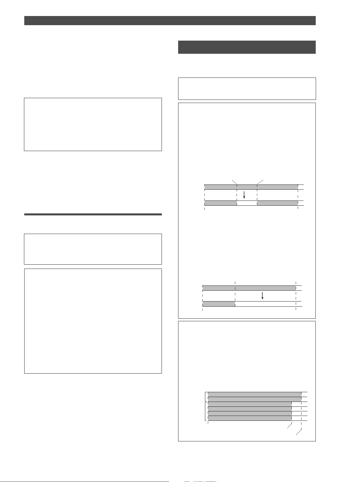
Editing Tracks
7.Press the EXECUTE/YES key.
[Copy Paste] (or [Move Paste]) flashes and the duration
of the pasted data appears as a negative number on the
display. This number will count down as the paste
operation proceeds.
When the paste operation is complete, the flashing [Copy
Paste] (or [Move Paste]) lights up continuously, and
[COMPLETED !] is displayed.
<Note>
If you try to execute the paste operation by pressing the EXECUTE/
YES key when the disk has insufficient free space, [Over !] appears
on the display and edit mode is cancelled. In this case, you need to
delete unnecessary data or Programs. Refer to the following section, “Erase,” and to “Erasing a Program” on page 38 for more information on erasing.
8.Press the STOP button or the EXIT/NO key.
The FD-4 exits edit mode and displays the previous Time
Base indication.
9. Turn off the RECORD TRACK select key of the copy (or move)
source track.
Undo/Redo Paste
Erase
There are two methods for erasing data. Understand the
difference between these methods before you use the Erase
function.
* If multiple Programs are set on the disk, first select the desired
Program. Do not select another Program until you finish the erase
operation.
• Erasing a specified part of the data between ABS 0 and
REC END
You may erase a specified part of the data between ABS 0 and REC
END (the end point of the recording) in the currently-selected Program. (The erased part is replaced with silence.)
You can erase data on a mono track and multiple tracks (including
Real tracks and Additional tracks).
As shown below, the REC END point (the end point of recording) is
not affected. The erased area is replaced with silence. As a result,
the REMAIN time and space will increase. (You will have more recordable space on the disk.)
AUTO PUNCH IN point
Any track
Any track
ABS 0
Erase
Silence
AUTO PUNCH OUT point
REC END
You can undo or redo a Copy & Paste and Move & Paste
operation.
• T o restore the data that existed prior to the paste operation, press
the UNDO/REDO key.
• T o restore the pasted data after you undo the paste operation,
press the UNDO/REDO key again.
<Note>
The Undo/Redo function is effective only when the FD-4 is stopped.
<Note>
If you perform one of the following operations after you use the
Copy & Paste or Move and Paste operation, the Undo/Redo function will no longer be effective.
1. When a new recording is made.
2. When a new editing is executed (such as Copy & Paste, Move &
Paste, Erase).
3. While in the AUTO PUNCH ON mode, when the AUTO PUNCH
IN point is passed in the PLAY (or RECORD) mode.
4. When the power is momentarily switched off.
5. When the program is changed.
6. When the disk is ejected. Erase
• Erasing data from a specified point to REC END
You may erase all data in the range from a specified point to REC
END in the currently-selected Program. You can erase data on a
mono track and multiple tracks (including Real tracks and Additional
tracks). When you erase all the tracks’ data, the REC END point will
move backward. However, if you erase data on a mono track or
multiple tracks (but not all tracks), the REC END point may not be
affected. (Refer to the note below.) After the erase operation, the
REMAIN time and space will increase.
AUTO PUNCH IN point
Any track
Any track
ABS 0
AUTO PUNCH OUT point
Erase
Silence
REC END
<Note>
The REC END point is the end point for recording on the Real tracks.
The Erase function uses the REC END point on the Real tracks,
even if the recording end point on an Additional track is located later.
If all tracks contain data as shown below, you need to specify the
recording end point of the Additional track (or later point) as an erase
end point in order to erase the data from the specified point. You
need to move the Additional track data to a Real track to find out
where the REC END point is.
58
Additional
track
Real track
ABS 0
Real track REC END
Additional track REC END
Page 59
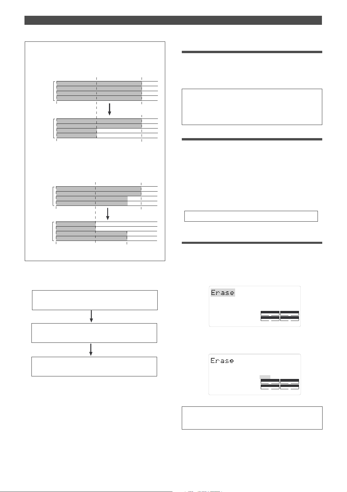
Editing Tracks
<Note>
If all Real tracks contain data as shown below, erasing data on
tracks 1 and 2 will not affect the position of REC END.
AUTO PUNCH IN point
4
ABS 0
ABS 0
3
2
1
4
3
2
1
Real track
Real track
On the other hand, if all Real tracks contain data as shown below,
erasing data on tracks 3 and 4 will move up REC END to the end
point of tracks 1 and 2.
AUTO PUNCH IN point
4
Real track
Real track
3
2
1
ABS 0
4
3
2
1
ABS 0
AUTO PUNCH OUT point
(REC END)
REC END
AUTO PUNCH OUT point
(REC END)
REC END
REC END
Storing the edit points
1.Refer to the “Storing and editing the locate points to the
memory keys” section for information on storing the erase
start and end points.
Store the erase start point to the CLIPBOARD IN key, and
the end point to the CLIPBOARD OUT key.
• If you wish to erase the data from a specific point, store the REC
END or later point as the erase end point. Refer to the note above
for information on storing the REC END point.
• See “Storing and editing the locate points to the memory keys” on
page 63.
Checking and adjusting the edit points
After you store the edit points, you can check them on the
display by pressing the corresponding keys.
You may also adjust the points.
1.While the recorder section is stopped, press and hold down
the SHIFT key and press the memory key for which you wish
to check the edit point.
You can preview “fade-out” at the AUTO PUNCH IN point
and “fade-in” at AUTO PUNCH OUT point.
2.Trim the edit point while previewing.
• Refer to “Preview Function” on page 69 for more information.
Executing Erase
1.Press the RECORD TRACK select key of the track to erase
to set it READY .
You can select a mono track, multiple tracks, or all tracks.
Follow the steps below to erase data:
Store the erase start point (AUTO PUNCH IN point) and
the erase end point (AUTO PUNCH OUT point).
Use the Preview function to check the stored edit points
and adjust them if necessary .
Specify a track to erase and execute the function.
2.Press the EDIT key repeatedly until [Erase] flashes on the
display.
SYNC OUT
CLK
AUTO A.PUNCH
DRIVE
SCSI
3.Press the EXECUTE/YES key.
The flashing [Erase] message lights up steadily, and
[SURE ?] flashes.
SURE ?
SYNC OUT
CLK
AUTO A.PUNCH
DRIVE
SCSI
• To cancel the erase operation, press the STOP button or the
EXIT/NO key while [SURE ?] flashes on the display.
59
Page 60
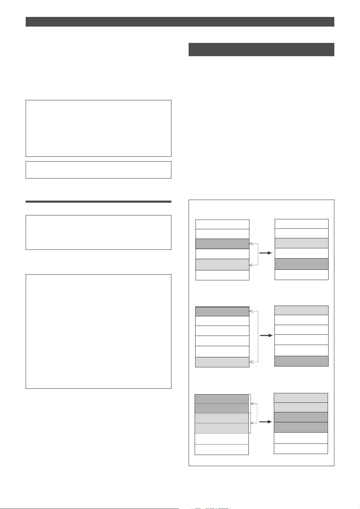
Editing Tracks
4.Press the EXECUTE/YES key again.
The FD-4 starts erasing the data and [Erase ....] flashes.
When the erase operation is completed, [COMPLETED !]
lights up.
5.Press the STOP button or the EXIT/NO key.
The FD-4 exits edit mode and displays the previous Time
Base indication.
• T o erase the data in its entirety from the tracks, you can also use
the Program Delete function to erase the entire Program.
In either case, you can expand the recordable area on the disk.
Use either one of the erase operations to erase unnecessary
data if the FD-4 displays an alarm message indicating insufficient
recordable space for Auto Punch In/Out, Copy & Paste, or Move
& Paste.
• Refer to “Deleting a Program” on page 38 for more information
on the Program Delete function.
Undo/Redo Erase
You can undo or redo the Erase operation.
• T o restore the data that existed before you erased it, press the
UNDO/REDO key .
• T o restore the data after you undo the Erase operation, press the
UNDO/REDO key again.
When you press the UNDO/REDO key, the FD-4 will undo or redo the
operation immediately, and display [Undo!] or [Redo !] and [COMPLETED !].
<Note>
The Undo/Redo function is effective only when the FD-4 is stopped.
<Note>
If you perform one of the following operations after you use the
Copy & Paste or Move and Paste operation, the Undo/Redo function will no longer be effective.
1. When a new recording is made.
2. When a new editing is executed (such as Copy & Paste, Move &
Paste, Erase).
3. While in the AUTO PUNCH ON mode, when the AUTO PUNCH
IN point is passed in the PLA Y (or RECORD) mode.
4. When the power is momentarily switched off.
5. When the program is changed.
6. When the disk is ejected.
Track Exchange
The Track Exchange function enables you to swap mono
track data or multiple track data of the current Program.
You can swap mono track data between Real tracks and
Additional tracks. You can swap multiple track data between
two Real tracks (1–2, or 3–4) and Additional tracks (L and
R).
Refer to the diagrams below for information on how data
on the tracks can be moved using this function.
The Track Exchange function also enables you to move Real
track data to an empty Additional track (to empty the original Real track) so that you can use the Real track for a new
recording. This application adds flexibility to the usage of
tracks. You can move data on the Additional track back to
the Real track to audition the data, since data in an Additional track cannot be played in real-time.
You can also use this function when you wish to check the
REC END point of the Additional track, as described in the
“Erase” section.
Swapping data between Real tracks (mono track data)
<After swap><Before swap>
Additional track R
Additional track L
Real track 4
Real track 3
Real track 2
Real track 1
Swapping data between a Real track and an Additional track (mono
track data)
Additional track R
Additional track L
Real track 4
Real track 3
Real track 2
Real track 1
Swapping data between Real tracks and Additional tracks (multiple track data)
Additional track R
Additional track L
Real track 4
Real track 3
Real track 2
Real track 1
Additional track R
Additional track L
data on Real track 2
Real track 3
data on Real track 4
Real track 1
data on Real track 1
Additional track L
Real track 4
Real track 3
Real track 2
data on Additional track R
data on Real track 4
data on Real track 3
Additional track R
Additional track L
Real track 2
Real track 1
60
Page 61
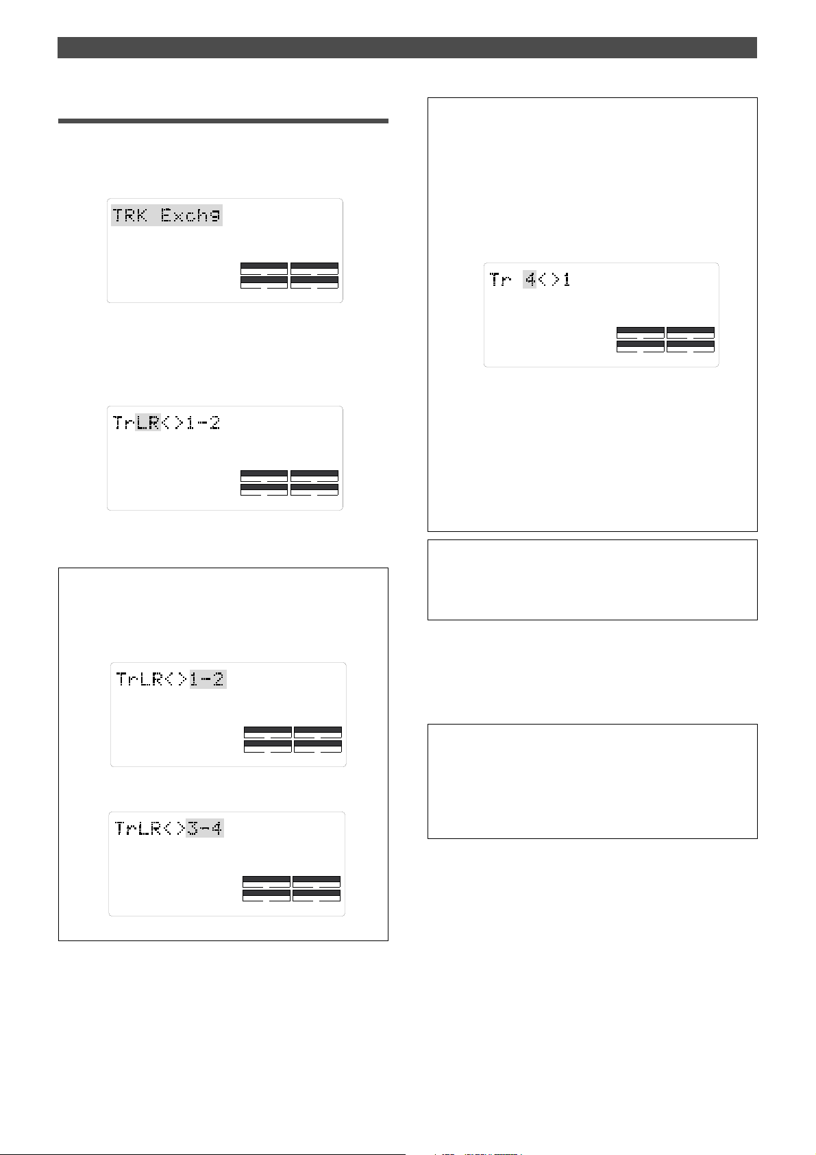
Editing Tracks
Executing Track Exchange
1.While the FD-4 is stopped, press the EDIT key repeatedly
until [TRK Exchg] flashes on the display.
Alternatively, you can press the EDIT key, then use the
JOG dial.
SYNC OUT
CLK
AUTO A.PUNCH
2.Press the EXECUTE/YES key.
The display shows the track selection.
The current display shows that you can swap two-track
data between Additional tracks L/R and rear tracks 1–2.
If you wish to select other tracks, follow the steps below.
SYNC OUT
CLK
AUTO A.PUNCH
DRIVE
DRIVE
SCSI
SCSI
• Swapping mono track data
1.When [L–R] is flashing, turn the JOG dial.
Turning the JOG dial allows you to select a mono track
from [1], [2], [3], [4], [L], and [R] in the left column.
The right column continues to indicate [1].
For example, if you select [4] in the left column, the
display indicates [4<>1], meaning you can swap data
between tracks 4 and 1.
SYNC OUT
CLK
AUTO A.PUNCH
DRIVE
SCSI
2. To select a number in the right column, press the
HOLD/> key, the REWIND button, or the F FWD button
to move the flashing cursor to the right column, then
use the JOG dial to select the desired number.
* When you swap data between mono tracks, the indications [4<>1]
and [1<>4], for example, mean the same thing — swapping data
between tracks 1 and 4.
3.Select the tracks to swap data.
• Selecting Additional tracks L–R and Real tracks 3–4:
1.Press the HOLD/> key, the REWIND button, or the F FWD
button to move a flashing cursor on [L–R] (left) to
[1–2](right).
SYNC OUT
CLK
AUTO A.PUNCH
DRIVE
SCSI
2.Turn the JOG dial to change flashing [1–2] to flashing
[3–4].
SYNC OUT
CLK
AUTO A.PUNCH
DRIVE
SCSI
<Note>
If you select the same tracks for swapping mono track data, the
setting is ignored. The FD-4 will indicate [Select Err] for a short moment, then return to the previous display.
4.Press the EXECUTE/YES key.
[Exchange] lights up and the swapping operation is
completed immediately.
The FD-4 indicates [COMPLETED !], then returns to the
previous Time Base display.
* Y ou cannot play data or check the REC END point on the
Additional tracks. T o do so, you need to move the data to a
Real track.
If you load back-up data from an external DA T recorder , the
data maintains the same condition as when you previously
saved it to DA T.
61
Page 62

Cue & Review Function
ABS
PGM
SMF
DRIVE
AUTO A.PUNCH
SYNC OUT
CLK
SCSI
Cue & Review Function
This chapter explains how to use the “Cue & Review function” with the REWIND button, the F FWD button, and the
JOG/SHUTTLE feature. Using this function enables you to
fast forward or rewind at different speeds while the recorder
section is playing or stopped.
During the Cue & Review operation, you will hear the sound
recorded on the disk, which makes it easy for you to locate
the desired point.
Cue & Review function using the REWIND and
F FWD buttons
You may cue & review the audio data at three-times speed
while the recorder is playing.
1.Press the PLAY button to play the audio data.
2.Press the F FWD button during playback.
[FWD>] appears on the display, and the FD-4 cues in the
forward direction at three-times speed.
ABS
3.Press the PLAY button again to restore the original play
back speed.
4.Press the REWIND button instead of the F FWD button.
[<RWD] appears on the display, and the FD-4 cues in the
reverse direction at three-times speed.
ABS
SMF
SYNC OUT
CLK
AUTO A.PUNCH
SMF
SYNC OUT
CLK
AUTO A.PUNCH
PGM
DRIVE
PGM
DRIVE
SCSI
SCSI
Cue & Review function using the SHUTTLE feature
You may cue and review data at a speed from normal to 64times speed, using the SHUTTLE feature while the recorder
is playing.
EQ
EQ
2
13
1.Press the PLAY button to start playback.
2.Hold down the SHIFT key and turn the JOG dial clockwise or
counter-clockwise.
Turning the JOG dial clockwise will change the cueing
speed. Turning the JOG dial counter-clockwise will change
the reviewing speed.
The FD-4 displays the selected cue or review speed, which
you can select from normal, two-times, four-times, eighttimes, 16-times, 32-times, and 64-times speed.
As long as you are holding down the SHIFT key, playback
continues at the selected speed.
ABS
SMF
PGM
DRIVE
SYNC OUT
CLK
AUTO A.PUNCH
SCSI
<Display of 16-times review>
<Display of 32-times cue>
5. Press the PLAY button to restore the original playback speed.
3.Release the SHIFT key to cancel the cue and review
Digital scrubbing using the JOG dial
operation.
The recorder resumes playback at the original speed.
You may perform digital scrubbing while the recorder section is stopped.
1.Turn the JOG dial clockwise or counter-clockwise while the
recorder section is stopped.
You can perform digital scrubbing in the forward or
reverse direction.
[FWD>] or [<REW] appears on the display.
When you release the JOG dial, [STILL] appears, and the
transport section stops.
2.Press the STOP button to cancel digital scrubbing.
<Note>
The cue and review operation does not affect pitch. Because the
FD-4 performs this function by skipping part of data during playback.
<Note>
When the beginning of the disk is reached during the review operation, the FD-4 starts normal playback, even if you are still holding
down the SHIFT key . When the end of the disk (ABS time: 23H 59M
59S) is reached during the cue operation, the FD-4 stops and the
PLA Y button LED flashes.
62
Page 63
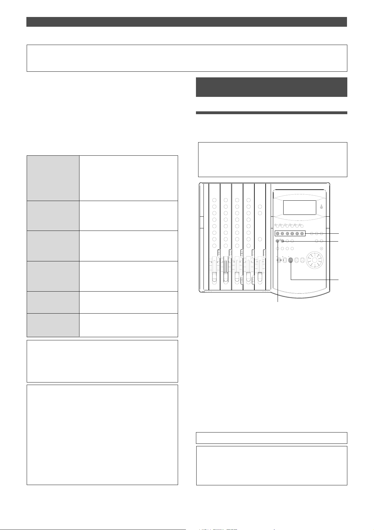
Storing a Locate Point (Edit Point)
Storing a Locate Point (Edit Point)
You can store time information (time or bar/beat/clock) in
each memory key. The stored time information will be used
to locate a point in data in the recorder section, or as an
edit point to perform the Auto Punch In/Out, Copy & Paste,
Move & Paste, or Erase function.
This chapter describes how to store data in the memory
keys and edit the stored data.
Data stored in the memory keys is used in the following
operations:
Locating the AUTO PUNCH IN point
Recording start point for the Auto Punch In/
AUTO PUNCH IN key
AUTO PUNCH OUT
key
CLIPBOARD IN key
CLIPBOARD OUT key
AUTO RTN ST AR T key
AUTO RTN END key
Out operation
Paste start point for the Copy & Paste or Move
& Paste operation
Erase start point for the Erase operation
Locating the AUTO PUNCH OUT point
Recording end point for the Auto Punch In/Out
operation
Erase end point for the Erase operation
Locating the CLIPBOARD IN point
Copy start point for copying or moving data to
the clipboard during the Copy & Paste or Move
& Paste operation
Locating the CLIPBOARD OUT point
Copy end point for copying or moving data to
the clipboard during the Copy & Paste or Move
& Paste operation
Locating the AUTO RTN START point
Locate end point from AUTO RTN END in Auto
Return or Auto Repeat modes
Locating the AUTO RTN END point
Locate start point to AUTO RTN ST ART in Auto
Return or Auto Repeat modes
<Note on storing the locate point>
When you set the IN/OUT points for Auto Punch In/Out, IN/OUT
points for Copy & Clip/Move & Clip, and START/END points for
Auto Return/Auto Repeat, make sure that IN points precede the
OUT points and STAR T points precede the END points.
• You can store locate points for each Program. (Y ou need to
select a Program first.)
• The data can be also saved or loaded even after the Song data is
saved or loaded.
• All locate points stored in the memory keys will be maintained
after you turn off the FD-4.
In addition to the memory keys, you can store data in the
LOCATE key in real-time. The LOCATE key always stores the
point most recently located by the FD-4. That is, data in the
LOCATE key is overwritten by new data each time the FD-4
locates a point. You can also edit the data in the LOCATE key .
Refer to the following pages for more information on how to edit
data.
Storing and editing the locate points to the
memory keys
Storing in real-time
You can store the locate point (in the ABS, MTC, or BAR/
BEAT/CLK Time Base) in real-time while the FD-4 is
playing.
• Select the desired Time Base using the TIME BASE SEL key
if you wish to use a Time Base other than ABS.
• The stored or edited locate points are used only in the currentlyselected Program.
EQ
EQ
4
3
1
2
1.Press the PLAY button to play back data.
2.When the point you wish to store is reached, press the
HOLD/> key.
The time value or bar/beat/clock value of the point is
captured. The FD-4 enters data edit mode.
3.Press the STORE key.
The STORE LED lights up.
4.Press the desired memory key.
The STORE LED turns off.
The captured time value (or bar/beat/clock value) is
stored in the memory key. After the data is stored, the
FD-4 displays the previous Time Base and continues
playback.
• You can omit Step 2 above to speed operation.
• If you set “BAR/BEAT Resolution mode” in SETUP mode to ON,
the FD-4 will round off the CLK value of the captured bar/beat/
clock value. That is, the locate point will be at the beginning of the
beat (00). Refer to page 92 for more information.
63
Page 64
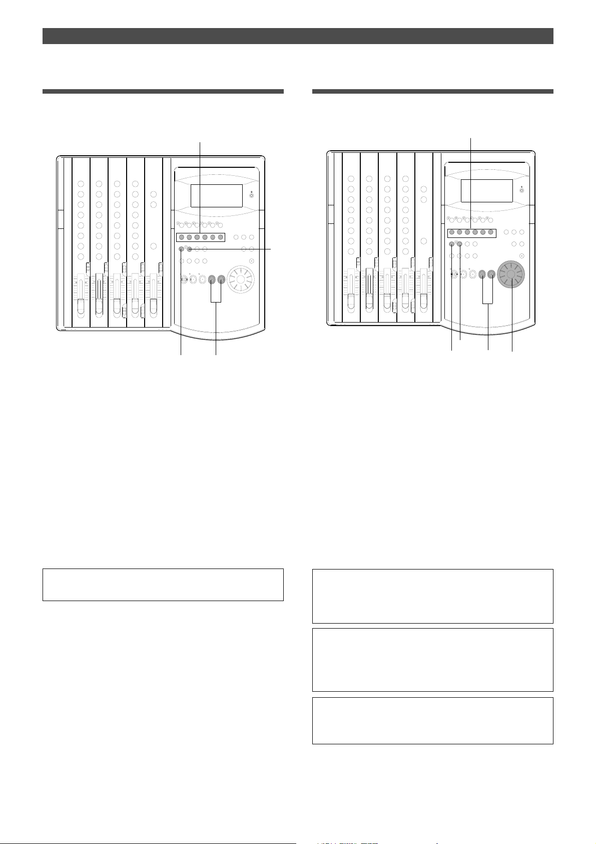
Storing a Locate Point (Edit Point)
Editing and storing locate data
If you know the position of the desired locate point, follow
the steps below.
4
EQ
EQ
3
1, 2
2
Editing and storing data
You can recall data stored in the memory key, edit it, and
store it. again
1, 4
EQ
EQ
3
2
2
2
1.Press the HOLD/> key while the FD-4 is stopped.
The currently-displayed time value (or bar/beat/clock
value) is captured and the FD-4 enters data edit mode.
2.Press the HOLD/> key, REWIND button, or the F FWD button
to move the flashing cursor on the time value digit, and use
the JOG dial to increase or decrease the value.
3.Press the STORE key.
The STORE LED lights up.
4.Press the desired memory key.
The STORE LED turns off.
The input time value (or bar/beat/clock value) is stored
in the corresponding memory key.
• Press the STORE key instead of the HOLD/> key in Step 1 above
and omit Step 3 to speed operation.
1.While the FD-4 is stopped, press the memory key that stores
the data you wish to edit.
The stored data appears on the display and the FD-4
enters data edit mode.
2.Press the HOLD/> key, REWIND button, or the F FWD button
to move the flashing cursor to the time value digit, and use
the JOG dial to increase or decrease the value.
3.Press the STORE key.
The STORE LED lights up.
4.Press the memory key that you pressed in Step 1 again.
The STORE LED will turn off.
The edited data is stored, and the FD-4 displays the
previous Time Base indication.
• You can store the edited data in a memory key other than the one
you pressed when you recalled the data. For example, you can
recall the AUTO PUNCH IN point data, edit it, and store it to the
AUTO PUNCH OUT key .
• Refer to page 43 for more information on Auto Punch In/Out.
• Refer to page 56 for more information on Copy & Paste, Move &
Paste, and Erase.
• Refer to page 66 for more information on Auto Return and Auto
Repeat.
64
• You can also use the Preview function to edit the stored locate
points (edit points). Refer to “Preview Function” on page 69 for
more information.
Page 65

Editing the data stored in the LOCA TE key
You can recall the last located point and edit the value.
You can use the edited value to locate the point later or
store it to another memory key.
4
EQ
EQ
2
3
1
Storing a Locate Point (Edit Point)
2
2
1.Press the SHIFT and LOCATE keys simultaneously while
the FD-4 is stopped.
The last located point stored in the LOCATE key appears
on the display and the FD-4 enters data edit mode.
If no data is stored (that is, if the FD-4 has not located any
point since the power was turned on), 00H 00M 00S 00F
00SF appears and “00” of the digits “00S” flashes.
2.Press the HOLD/> key, REWIND button, or the F FWD button
to move the flashing cursor to the time value digit, and use
the JOG dial to increase or decrease the number to the
desired value.
3.To located the edited point, press the LOCATE key .
When you execute the Locate function, the locate point is
stored as locate data in the LOCATE key.
4.To store the edited data to another memory key, input the
desired value, press the STORE key, then press the desired
memory key.
The data is stored to the corresponding memory key.
The data stored in the LOCATE key will not change.
<Note>
You cannot preview the data stored in the LOCA TE key , unlike other
memory keys.
65
Page 66
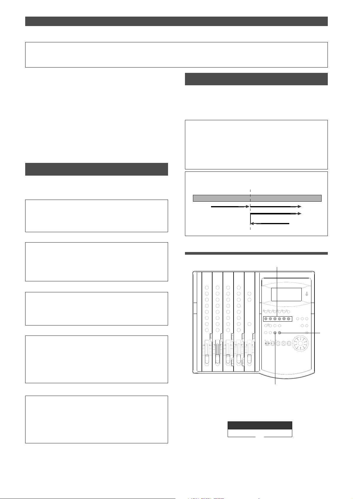
Locate Function
Locate Function
The FD-4 locates the desired edit point immediately (that
is, it moves the current position of the data in the recorder
section).
Locate points include edit points (in ABS time, MTC time, or
in bar/beat/clock) that are stored for the Copy, Move, Paste,
Erase, and Auto Punch In/Out operations.
They also include the top of a Program (ABS 0), the
recording end point in a Program (REC END), and a direct
locate point for which you can specify the time.
You can also use the Auto functions, such as Auto Play,
Auto Return, and Auto Repeat, with the Locate function.
Direct Locate
The Direct Locate function enables you to locate the following points:
• Locate the beginning of the Program (LOCA TE ABS 0)
Press the REWIND button while holding down the STOP button. The
FD-4 will immediately locate the beginning of the currently-selected
Program.
• Locate the recording end point of the Program (LOCA TE
REC END)
Press the F FWD button while holding down the STOP button. The FD4 will immediately locate the end point of the currently-selected Program.
Auto Play
The Auto Play function allows the FD-4 to start play back
automatically from the located point. AUTO PLAY mode
should be turned on before you execute the Direct Locate
function described above.
<Note>
This function is effective within 24 ABS hours. Therefore, if playback
continues over the recording end point, the FD-4 will still continue counting the time. Also, when the FD-4 locates ABS REC END, it will continue
counting the time from the recording end point. (However, the FD-4 does
not access the disk after reaching the recording end point.)
(Example) Locating the AUTO PUNCH IN point
AUTO PUNCH IN point
Locate
Playback
Locate
Executing the Auto Play function
2
• Locate the position stored in one of the memory keys
Press the desired memory key, then press the LOCA TE key . The FD-4
will locate the point (edit point) stored in the corresponding memory key
immediately.
• Locate a specified point
Refer to “Editing and storing locate data” in the chapter “Storing a Locate Point (Edit Point)” for information on how to edit the data and on
pressing the LOCATE key instead of the STORE key. The point at
specified time value (or bar/beat/clock value) will be located immediately.
• Locate the last-located point
Press the LOCATE key.
Since the LOCATE key always stores the last-located point (excluding
LOCATE ABS 0 and LOCA TE REC END), just press the LOCA TE key
to locate the last-located point again.
EQ
EQ
3
1
1.Press the AUTO RTN/AUTO PLA Y key to turn on the [PLA Y]
indicator on the bottom of the display.
AUTO
PLAY
2.Press the desired memory key.
66
Page 67
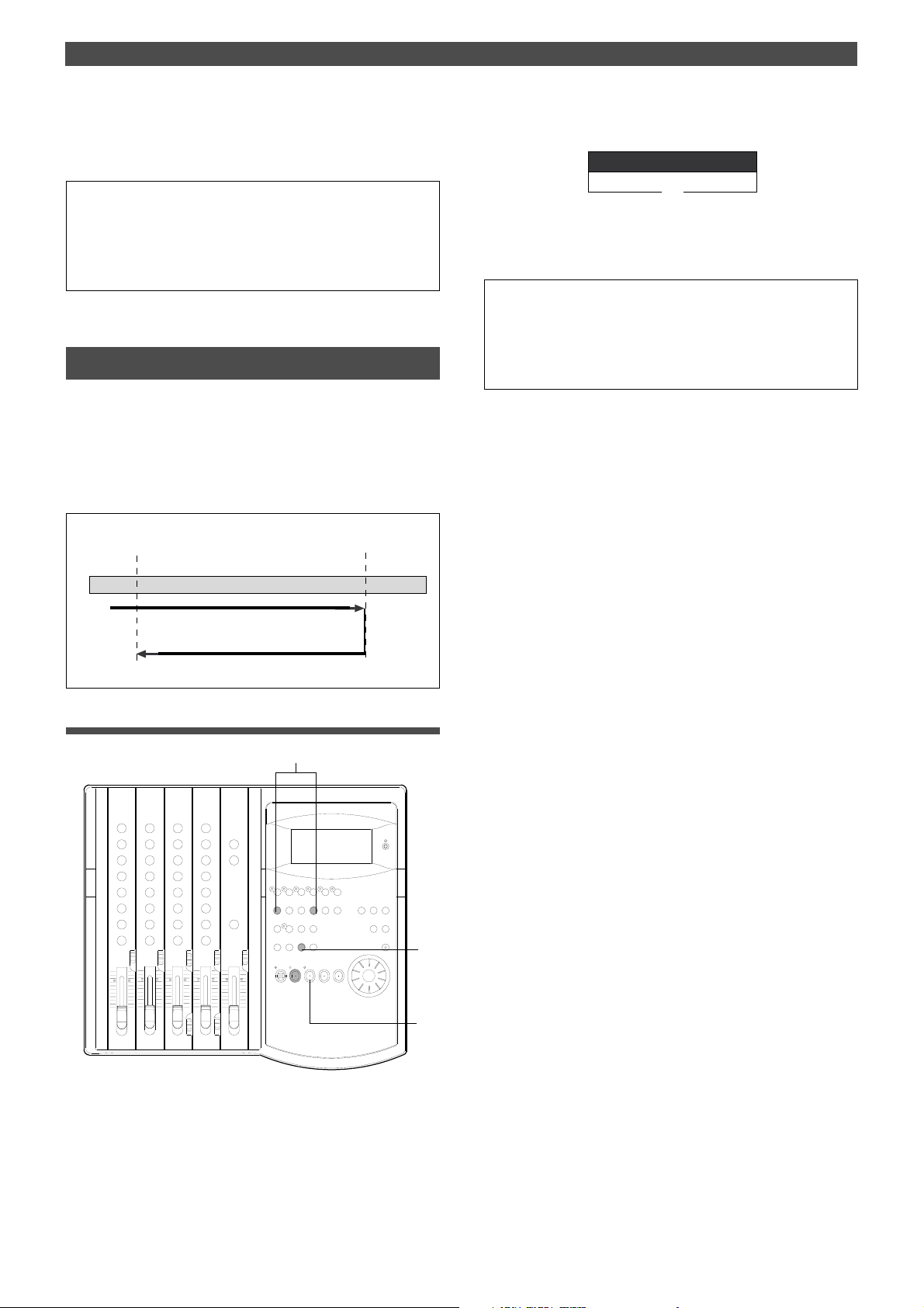
Locate Function
RTN
AUTO
3.Press the LOCATE key.
The FD-4 locates the point and plays as shown in the
diagram.
• You can set a preroll time in the [Preroll ?] menu in SETUP mode
so that the FD-4 will start playback preroll time before the locate
point. You can set the preroll time from 0 to 10 seconds. Refer to
the chapter “Changing the Initial Settings (SETUP Mode)” on page
85.
Auto Return
This function allows the FD-4 to play data up to the AUTO
RTN END point, then automatically locate the AUTO RTN
START point as shown in the diagram below.
To enable this function, AUTO RTN mode should be on and
the AUTO RTN START point and AUTO RTN END point
should already be set.
<Auto Return operation>
AUTO RTN START point
AUTO RTN END point
2.Press the AUTO RTN/AUTO PLAY key to turn on the [RTN]
indicator at the bottom of the display.
3.Start playback a little before the AUTO RTN END point.
The FD-4 operates as shown in the diagram and stops at
the AUTO RTN START point.
• You can set a preroll time in the [Preroll ?] menu in SETUP mode
so that the FD-4 will start playback preroll time before the locate
point. Y ou can set the preroll time from 0 to 10 seconds. Refer to
the chapter “Changing the Initial Settings (SETUP Mode)” on page
85.
Playback
Stop
Locate
Executing the Auto Return function
1
EQ
EQ
2
3
1.Store the AUTO RTN ST AR T and AUTO R TN END points.
Refer to the chapter “Storing a Locate Point (Edit Point)”
on page 63 for information on storing the desired points
in the AUTO RTN START key and the AUTO RTN END
key.
67
Page 68
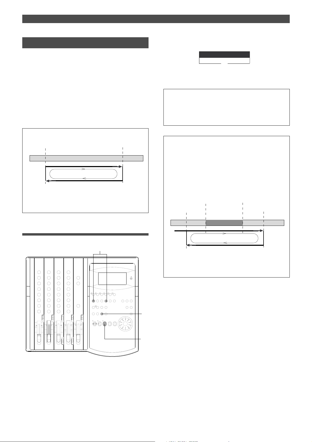
Locate Function
PLAY RTN
AUTO
Auto Repeat
The Auto Repeat function allows the FD-4 to repeat playback up to the AUTO RTN END point, automatically locate
the AUTO RTN START point, then play up to the AUTO RTN
END point until you cancel the function by pressing the
STOP button. To enable this function, both AUTO PLAY
mode and AUTO RTN mode should be turned on, and the
AUTO RTN START point and the AUTO RTN END point
should already be set.
Using this function will facilitate the Auto Punch In/Out
and Manual Punch In/Out rehearsal. See “Hint” after the
following section.
<Auto Repeat operation>
AUTO RTN START point
Playback
Locate
When the AUTO RTN END point is reached, the
FD-4 will locate the AUTO RTN START point, then
start playback from that point. The FD-4 will repeat
this operation until you stop it.
AUTO RTN END point
2.Press the AUTO RTN/AUTO PLAY key to turn on the [PLA Y
RTN] indicator on the bottom of the display.
3.Start playback a little before the AUTO RTN START point.
The FD-4 operates as shown in the diagram, and stops at
the AUTO RTN START point.
• You can set a preroll time in the [Preroll ?] menu in SETUP mode
so that the FD-4 will start playback preroll time before the locate
point. You can set the preroll time from 0 to 10 seconds. Refer to
the chapter “Changing the Initial Settings (SETUP Mode)” on page
85.
<Hint>
You can make repeated Auto Punch In/Out rehearsal much easier
and quicker by using the Auto Repeat function. Set the AUT O RTN
ST ART point prior to the AUTO PUNCH IN point, and set the AUT O
RTN END point after the AUTO PUNCH OUT point. The recorder
will repeat the operation automatically so you can concentrate on
your rehearsal.
Cancel Auto Repeat mode before you record a take.
AUTO PUNCH IN point
AUTO RTN STAR T point
AUTO PUNCH OUT point
AUTO RTN END point
Rehearsal range
Executing the Auto Repeat function
1
EQ
EQ
1.Store the AUTO RTN ST AR T and AUTO R TN END points.
Refer to the chapter “Storing a Locate Point (Edit Point)”
on page 63 for information on storing the desired points
in the AUTO RTN START key and the AUTO RTN END
key.
Playback
Locate
The FD-4 will play this range repeatedly for rehearsal, which
makes it easy for you to check the recording level and practice
your performance.
2
3
68
Page 69
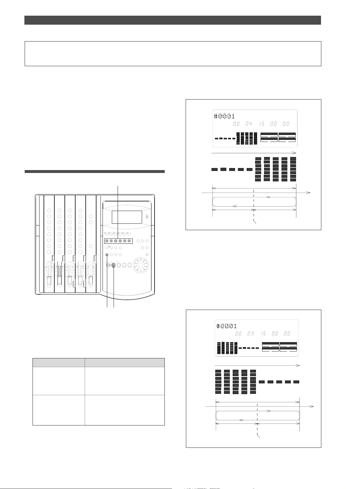
Preview Function
Preview Function
The preview function enables you to repeatedly audition
the rise (fade in) or the fall (fade out) of the sound data at
a locate point (edit point) that is stored in the AUTO PUNCH
IN/OUT, AUTO RTN START/END, or CLIPBOARD IN/OUT
key. This is also called “point rehearsal.”
With this function, you can check the locate points in realtime.
You can also use this function to fine-tune the position of
the locate points while previewing the sound.
This function is effective only when the FD-4 is stopped.
Executing the Preview function
EQ
EQ
• Previewing the rise of the sound (fade in)
While holding down the SHIFT key, press the AUTO RTN
START key, the AUTO PUNCH OUT key, or CLIPBOARD IN
key.
<Display indication during the Preview operation>
ABS
LOC SMH
Approx. 2 sec.
Approx, 1 sec.
(mute playback)
The sound rises at the memory point.
The FD-4 repeats playback the “rise sound” at the locate point (edit
point). As shown in the diagram, one-second of data prior to the
locate point is muted during playback. The mute is off (fade in) at the
locate point and the sound is played back for one second.
The FD-4 will repeat this operation until you quit the Preview
function.
F
SYNC OUT
CLK SCSI
AUTO A.PUNCH
Approx, 1 sec.
(normal playback)
DRIVE
SF
112
1.Press the desired memory key while holding down the SHIFT
key when the FD-4 is stopped.
Pressing the desired memory key will enable you to
preview the sound at the locate point (edit point) stored
in the corresponding memory key.
Memory key
AUTO PUNCH IN key
AUTO RTN END key
CLIPBOARD OUT key
AUTO PUNCH OUT key
AUTO RTN ST AR T key
CLIPBOARD IN key
The FD-4 plays the fall (fade out) of the
sound at the locate point stored in the
keys.
The FD-4 plays the rise (fade in) of the
sound at the locate point stored in the
keys.
Refer to the following diagram for the display indication
during the Preview operation.
Operation
• Previewing the fall of the sound (fade out)
While holding down the SHIFT key, press the AUTO END
START key, the AUTO PUNCH IN key, or the CLIPBOARD OUT
key.
<Display indication during the Preview operation>
ABS
LOC SMH
Approx, 1 sec.
(normal playback)
Approx. 2 sec.
The sound falls at the memory point.
F
SYNC OUT
CLK SCSI
AUTO A.PUNCH
Approx, 1 sec.
(mute playback)
DRIVE
SF
69
Page 70
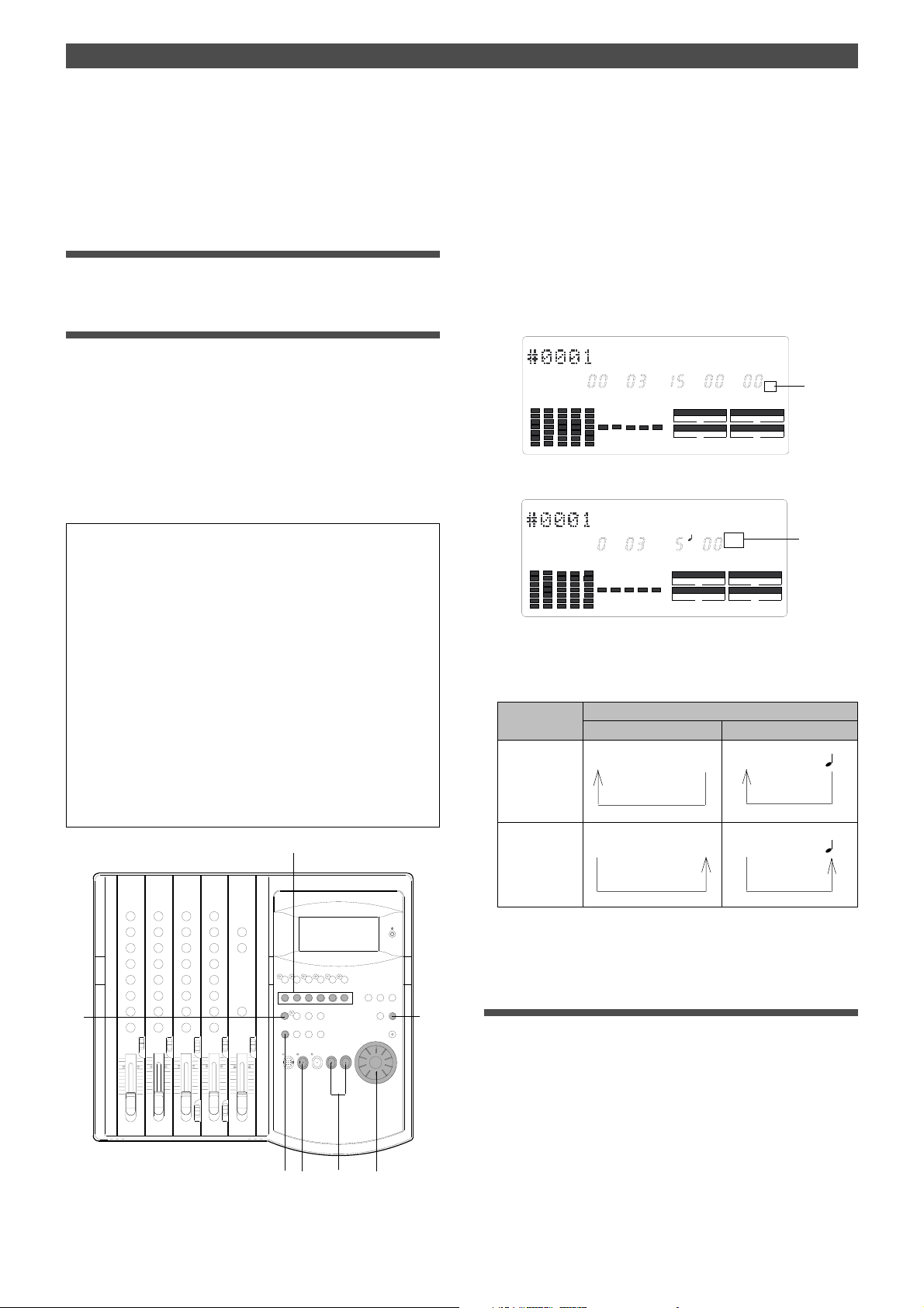
Preview Function
The FD-4 repeats playback of the “fall sound” at the locate point (edit
point). As shown in the diagram, one-second of data prior to the
locate point is played back, then muted (fade out) at the locate point.
The muted playback continues for one second. The FD-4 will repeat
this operation until you quit the Preview function.
Quitting the Preview function
2.Press the STOP button or the EXIT/NO key.
Trimming the sound while previewing
You can trim the position of the locate point (edit point)
using the JOG dial while you preview the sound.
At this time, you can also adjust the size of the trimming
steps (the amount of offset controlled by the JOG dial).
Trimming allows you to fine-tune the position of the locate
point stored in the memory keys while previewing the sound.
Use this function to change the Auto Punch In/Out points,
the start point of Copy & Paste and Move & Paste, and the
start and end points of the Erase function.
<Notes>
• You can audition the result of trimming during the next preview .
That is, if you trim the position while previewing the sound for the
first time, you can check the result when you preview the sound
next time.
1.Start previewing the sound by following the steps described
on the previous page.
2.Use the JOG dial to trim the position.
When previewing starts, the unit of JOG trimming flashes
on the screen. For example, SF (sub-frame) flashes if ABS
Time Base or MTC Time Base is selected. CLK (clock)
flashes if BAR/BEAT/CLK is selected.
The flashing value also indicates the position you can
trim.
(Example) Time Base is ABS: (SF flashes.)
ABS
LOC SMH
CLK SCSI
(Example) Time Base is BAR/BEAT/CLK (CLK flashes.)
LOC
BAR
CLK SCSI
F
SYNC OUT
AUTO A.PUNCH
CLK
SYNC OUT
AUTO A.PUNCH
DRIVE
DRIVE
SF
Flashing
Flashing
• If the locate point is shifted outside the range of the preview
playback as a result of trimming, [Void Data!] and the locate
point indication appear alternately. In this case, you cannot use
the Preview function. Trim the position again so that it will be
within the playback range.
• When Auto Punch mode is turned on and you trim the Auto
Punch In or Auto Punch Out point while previewing the sound
with [Void Data!] indicated on the display , Auto Punch mode will
be cancelled.
1
EQ
EQ
3
3.To change the unit of trimming, press the HOLD/> key, the
REWIND button, or the F FWD button.
These buttons will change the trimming unit as follows:
Time Base
ABS or MTC BAR/BEAT/CLK
HOLD/> key
or
F FWD button
REWIND
button
SF
->H ->M -> S ->
SF <-H
<- M <- S <-
CLK
->
CLK
<-
BAR ->
BAR
<-
F
F
4.Trim the position at the selected unit (digit).
Quitting the trimming function
5
5.Press the STOP button or the EXIT/NO key.
The trimmed locate point (edit point) data will be stored
in the corresponding memory key.
70
2, 4
1
3
5
Page 71
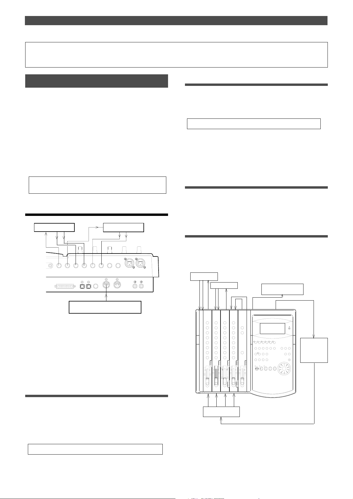
MIDI Synchronization
MIDI Synchronization
MIDI clock sync system
You can configure the sync system to use a stand-alone
sequencer synchronizing as a MIDI clock slave by inserting
time signature settings and tempo settings at any position
in a song using a programmable Tempo Map of the FD-4.
In this system, the recorder output of the FD-4 is routed to
the input channel faders, and up to four MIDI sound sources
connected to the input jacks are routed to the MON mix
section. In this way, you can mix down up to eight channel
sound sources without using an external mixing console.
You can also mix down digital signals to an external digital
master recorder by connecting MON OUT (L/R) of the FD-4
to RECORDER IN.
• Initialize the FD-4 before the operation.
• If multiple Programs exist, select the desired Program first.
Connecting and setting an external device
Effect unit 2
T OUT L
2 AUX SEND 1
AUX RTN 2
R MONO/L
SCSI
AUX RTN 1
R MONO/L
DATA
DATA
PUNCH
OUTIN
IN/OUT
Effect unit 1
4 INSERT 3
MIDI
INPUT 3
INPUT 4
MIDI
OUT
RECORDER IN
R
LIN
Creating a Tempo Map
1.Specify time signatures for the measures using the “Setting
a time signature” menu in SETUP mode. Then, specify the
tempo for given measures and beats using the “Setting a
tempo” menu in SETUP mode.
• See pages 82 and 83 for more information.
2.Play the FD-4 in play mode to see if the MIDI sequencer
synchronizes to the FD-4 according to the Tempo Map.
At this time, select the BAR/BEAT/CLK Time Base to see if
the MIDI sequencer synchronizes correctly.
Overdubbing
1.Overdub the syncing MIDI sound sources to tracks 1–4 as
described in the “Basic Recording and Playback” chapter.
You can also record a MIDI sound source as a guide.
Mixing down while syncing MIDI sound sources
When you finish overdubbing, proceed to mixdown.
As shown in the diagram, use the connected MIDI sound
sources as virtual tracks, synchronize them to the FD-4,
and mix down digital signals while applying effects.
Effect unit 1
Effect unit 2
Digital Master Recorder
MIDI sequencer
1.Connect the MIDI OUT jack of the FD-4 to the MIDI IN jack of
the MIDI sequencer.
2.Set the MIDI sequencer to “MIDI clock slave” mode, and
connect the MIDI sound source (played automatically) to the
input jack of the FD-4.
3.Connect the effect units, if desired.
Setting MIDI SYNC OUT
1.In the “Setting MIDI sync output signal” menu in SETUP
mode, select “MIDI clock (Clk)” for the MIDI sync signal
output.
If you wish to use the Metronome function, turn the
“Setting the Metronome function” menu in SETUP mode
to ON.
• See pages 85 and 86 for more information.
EQ
EQ
MIDI
Sequencer
MIDI sound sources
1.Set the channel 1–4 INPUT SEL switches to [TRK].
2.Set the SELECTOR in the monitor section to [L/R+MON].
71
Page 72
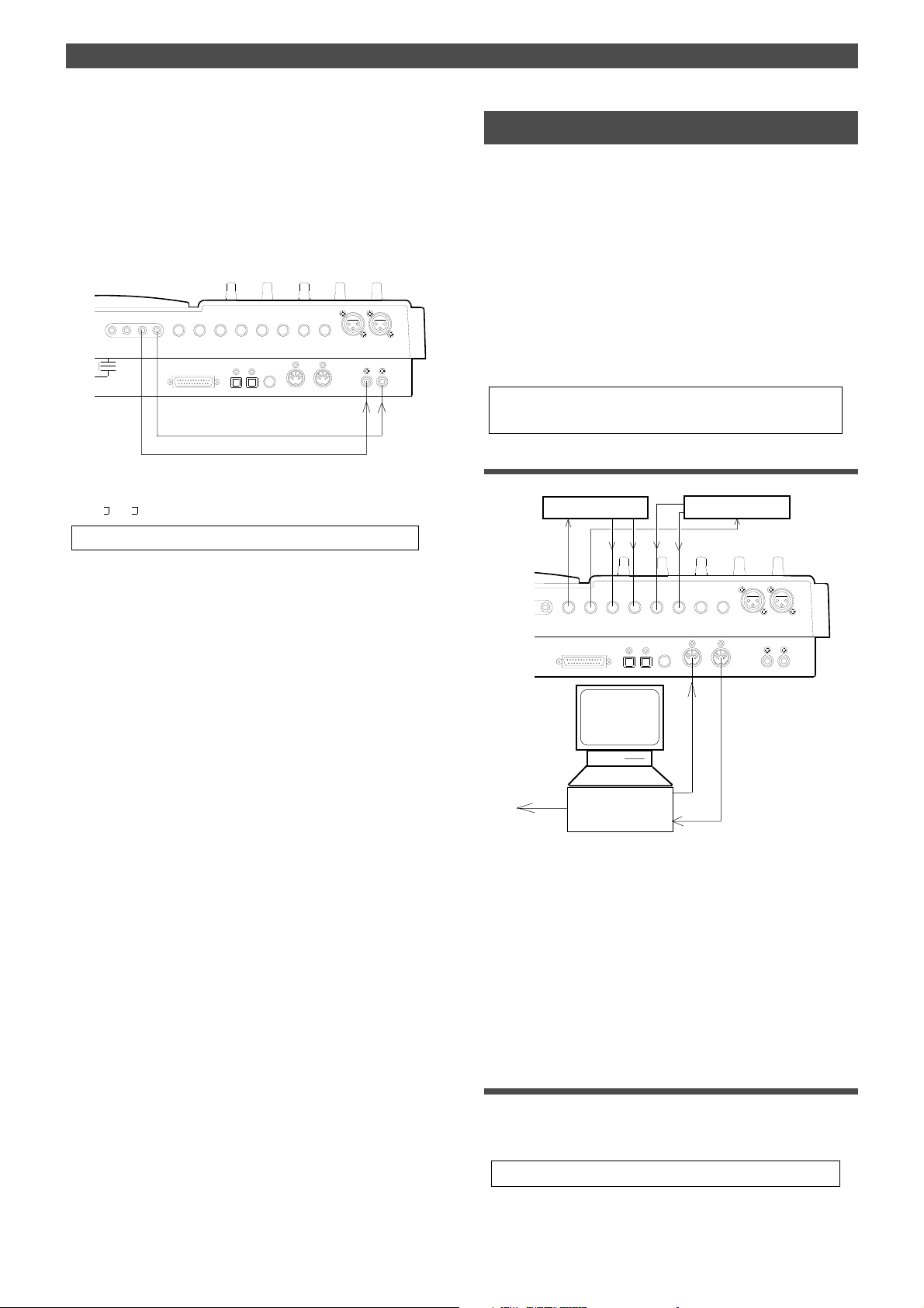
MIDI Synchronization
3.Raise the master faders L/R to [7–8].
4.Connect the MON OUT (L/R) jacks and the RECORDER IN
jacks directly.
This connection will route the L/R+MON signals output
from MON OUT (L/R) to the DATA OUT jacks via the
RECORDER IN jacks for mixdown. (The L/R+MON signals
included the playback signals from tracks 1-4 and four
MIDI sound sources.)
R MON OUT L
R ST OUT L
2 AUX SEND 1
AUX RTN 2
R MONO/L
SCSI
AUX RTN 1
R MONO/L
DATA
DATA
PUNCH
MIDI
OUTIN
IN/OUT
4 INSERT 3
INPUT 4
RECORDER IN
MIDI
R
OUT
LIN
INPUT 3
5.Set the “Setting digital output tracks” in SETUP mode to
[L– , r- ].
• See page 92 for more information.
MTC sync/Machine Control system
This section explains a synchronization system controlled
by a computer using MMC (MIDI Machine Control) and
controlled by MTC (MIDI time code) output from the FD-4.
The FD-4 adds a given offset value to the ABS time on the
disk and outputs the information as MTC of a given frame
rate. In addition, the FD-4 can receive external MMC and
Fostex System Exclusive Message (FEX) to perform certain
operations. Changing the device ID number included in the
messages transmitted from the computer allows you to control various operations on the FD-4 individually. Use the
“Setting the MIDI device number” menu in SETUP mode to
set the device ID number.
• Initialize the FD-4.
• If multiple Programs exist, select the desired Program first.
Connecting an external device
Effect unit 2 Effect unit 1
6.Use the input channel faders and the PAN knobs to adjust
the playback levels and stereo image of tracks 1–4.
Turn the MON knob in the MON mix section of the
corresponding channels toward [INPUT] to adjust the
input level of the MIDI sound sources, and use the MON
PAN knob to adjust the stereo image.
7.Use the MASTER knob in the monitor section to adjust the
final output level for mixdown.
8.If you wish to apply effects to a track, turn the AUX knob and
AUX RTN knob of the corresponding channel to adjust the
effect amount and balance.
INPUT 3
AUX RTN 2
T OUT L
2 AUX SEND 1
R MONO/L
SCSI
AUX RTN 1
4 INSERT 3
R MONO/L
DATA
DATA
PUNCH
OUTIN
MIDI
IN/OUT
MMC
INPUT 4
MIDI
OUT
RECORDER IN
R
LIN
MTC
Computer
MIDI
with MMC/MTC
compatible software
1.Connect the MIDI IN jack and MIDI out jack to the MIDI OUT/
IN jacks of the computer (using a MIDI interface).
The computer should be running sequence software that
supports MMC and MTC.
2.Set the sequence software to MTC slave mode and MMC
output mode, and select the desired MTC frame rate.
3.Connect the MIDI sound sources and effect units
accordingly, in the manner as explained in the “MIDI clock
sync system” section.
72
Setting MIDI SYNC OUT
1.Set the MIDI sync signal to be output to “MTC (Mtc)” in the
“Setting MIDI sync output signal” menu in SETUP mode.
At this time, select [MTC] for Time Base for convenience.
• Refer to page 86 for more information on SETUP mode.
Page 73

MIDI Synchronization
Setting MTC OFFSET
1.Set the time offset from the ABS time (less than six hours) in
the “Setting an MTC offset value” menu in SETUP mode.
• See page 88 for more information.
Setting a frame rate
1.Select the same MTC frame rate as that for the sequence
software in the “Setting an MTC frame rate” in SETUP mode.
• See page 87 for more information.
Setting the device ID number
1.Set the same device ID number as the MMC device number
for the sequence software and the FEX device number in
the “Setting the device ID number” menu in SETUP mode.
You do not set a number if the sequence software
transmits [7Fh], which means [ALL DEVICE].
• See page 93 for more information.
Checking synchronization and Machine Control
1.Operate the FD-4 in play mode, and check to see if the
sequence software synchronizes to the MTC output from
the FD-4.
Check to see if the FD-4 plays, stops, and locates points
correctly when it is controlled from the computer.
Overdubbing
1.Overdub on tracks 1 – 4 as explained in “Overdubbing” of
the “MIDI clock sync system” section.
Mixing down while syncing the MIDI sound sources
1.Synchronize the output from tracks 1–4 with four MIDI sound
sources, and mix down while applying the effects, as
explained in “Mixing down while syncing MIDI sound
sources” in the “MIDI clock sync system” section.
Effect unit 1
Effect unit 2
EQ
EQ
MIDI sound sources
Digital Master
Recorder
MIDI
MTC MMC
Computer
with MMC/MTC
compatible software
<Please read this>
About MMC REC Out function
If you use the MMC REC Out function, operating the FD-4 will cause the
MIDI OUT connector to output the MMC command that corresponds to
the operation.
For example, pressing the PLAY button while pressing the RECORD
button will output the MMC REC command from the MIDI OUT connector. The following commands are output:
Operation on the FD-4
PLAY + RECORD buttons
Punch In operation in TAKE mode
of Auto Punch In/Out.
Punch In operation via a footswitch.
RECORD button ON/OFF .
Rehearsal In in rehearsal mode of Auto
Punch In/Out.
Rehearsal In via a footswitch.
PLAY button
Punch out in TAKE mode
of Auto Punch In/Out
Punch out via a footswitch.
STOP button
Output MMC command
(Device No. = 7F fixed)
REC command
Input monitor ON/OFF command
REC EXIT command
STOP command
These MMC commands are output only when you operate the buttons
on the FD-4. They are not output when the FD-4 receives external MMC
commands.
You cannot turn off the MMC REC Out function. Whenever you perform
any of the operations described above, the corresponding command is
output. This is something you should note. If the sequencer connected
to the FD-4’s MIDI OUT is in record mode and you operate the FD-4,
the corresponding MMC command will be recorded in a track on the
sequencer. Then, if MIDI data is sent from the sequencer to the FD-4,
the MMC command recorded in the sequence data will cause the FD-4
to enter record mode.
73
Page 74
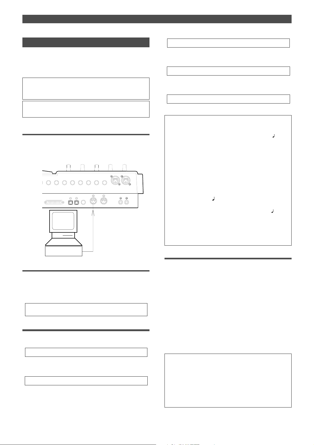
MIDI Synchronization
Sync system in Slave mode
You can set up the system in which the FD-4 in Slave mode
synchronizes to an external master MIDI device.
In this example, a master device is a computer running
sequence software.
<Note>
Make sure to use an external MIDI device that is able to output
MTC as a master device.
• Initialize the FD-4 before you start the operation.
• If multiple Programs exist, select the desired Program first.
Connecting an external device
1.Connect the MIDI OUT jack of a computer running sequence
software to the MIDI IN jack of the FD-4.
The connected computer should be running sequence
software that supports MMC/MTC.
INPUT 3
2 AUX SEND 1
AUX RTN 2
R MONO/L
SCSI
AUX RTN 1
R MONO/L
DATA
DATA
OUTIN
4 INSERT 3
PUNCH
MIDI
IN/OUT
MTC
INPUT 4
MIDI
OUT
RECORDER IN
R
LIN
* See “Setting Offset mode” on page 88 for more information.
4.Turn Slave mode ON in the “Setting the Slave mode” menu
in SETUP mode.
* See “Setting the Slave mode” on page 88 for more information.
5.Set the slave type to [Vari] in the “Setting the Slave type”
menu in SETUP mode.
* See “Setting the Slave type” on page 89 for more information.
6.Press the TIME BASE SEL key to display the MTC Time Base.
<Notes on setting MTC-related parameters>
The MTC offset time and MTC offset mode determines whether or
not MTC (MTC offset time) is output at ABS 0 or 001BAR 1
Follow the guide below, according to the start time of the song of the
sequence software.
• Offset mode = ABS:
Set the MTC offset time to three seconds prior to the start time of
the song of the sequence software. The FD-4 does not chase and
lock to incoming MTC immediately. To synchronize the FD-4 from
the beginning of the song, you need to set a preroll time and play
the song a little before the top of the song of the sequence software.
• Offset mode = BAR
:
You can set the MTC offset time to the start time of the song.
As explained previously , the ABS 0 position is [-002BAR 1
which allows for synchronization from the top of the song. The duration of two measures changes depending on the setting of the time
signature and the tempo of the first measure. (Example: slow tempo
= longer duration)
00CLK.
00CLK],
with Sequence
Software
Setting up the external device
1.Set the following items on the sequence software.
• Set up the sequence software to output MTC.
• Set a frame rate of MTC.
• Check the start time of the song.
* Refer to the instruction manual that comes with the external device
for more information.
Setting the FD-4
1.Set the frame rate of the sequence software, as described in
the “Setting an MTC frame rate” menu in SETUP mode.
* See “Setting an MTC frame rate” on page 87 for more information.
2.Set an offset time value in the “Setting an MTC offset value”
menu in SETUP mode.
* See “Setting an MTC offset value” on page 87 for more information.
3.Set the desired mode in the “Setting Offset mode” menu in
SETUP mode.
Checking the chase and lock operation
1.When you play the sequence software, the [MTC IN]
indicator on the display lights up, and the flashing [SLA VE]
lights up continuously, which indicates that chase and lock
is complete.
At this time, make sure that MTC output from the
sequence software is being displayed on the FD-4.
2.When you stop the sequence software, MTC transmission
is interrupted and the FD-4 stops.
The [SLAVE] indicator on the display starts flashing.
3.While the sequence software is fast forwarding or
rewinding, the FD-4 remains stopped. As soon as you start
play back or record, the FD-4 immediately performs the chase
and lock operation.
<Note>
The FD-4 can chase and lock to MTC only when the speed variation of
MTC sent from the master device (computer) is within +/-5.6%.
Within this range, the FD-4 will use the Vari Pitch function internally to
chase MTC. If this range is exceeded, the FD-4 cannot chase and lock.
If the speed variation of the master device is large, play the sequencer
before recording so that the FD-4 will learn the speed of the master
device. In this way , the FD-4 will lock to time code quicker next time.
74
Page 75

• If the FD-4 does not chase and lock correctly, check the connecting
cables and settings.
Recording
You can record data on the FD-4 while the FD-4 is chasing
and locking to the sequence software signals.
<Hint>
About the option “Vari” in the “Setting the Slave type” in SETUP
mode:
If the FD-4 chases and locks to only an incoming MTC, Vari Pitch is
applied all the time. Under this condition, if the FD-4 outputs digital
signals to a connected digital device, the device may not be able to
accommodate the FD-4’s speed variation (MTC speed variation of
the master device), resulting in interrupted signal input at the digital
device.
To solve this problem, set the “Setting the Slave type” menu to
“Free.” This will cause the FD-4 to follow its internal clock after it
finishes the chase and lock operation, supplying stable digital signals to the external digital device.
With the “Free” setting, if the MTC offset between the master and
slave devices exceeds “10 frames,” the slave device interprets this
as out of lock, and tries to chase and lock again (re-chase operation). During the re-chase operation, the audio output will be muted
and digital signal transmission is also interrupted. If the offset is
within 10 frames, the slave device will continue running while recognizing the offset.
MIDI Synchronization
<Note>
If you set the “Setting the Slave type” menu to “Vari,” the FD-4
applies Vari Pitch all the time to chase MTC.
However, if a digital input track is assigned in the “Setting digital
input tracks” in SETUP mode, the FD-4 will sync to incoming digital
signals (external wordclock sync). This means that the FD-4 will not
apply Vari Pitch during chasing even with the “Vari” setting.
The FD-4 will sync to incoming digital signals after it locks MTC.
75
Page 76
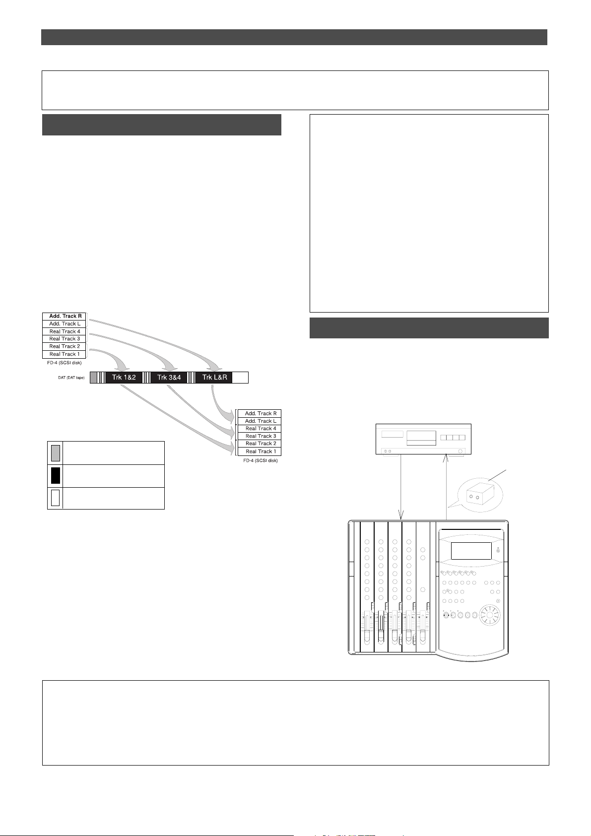
Saving and Loading Song Data
Saving and Loading Song Data
Outline of the save/load operation
The FD-4 enables you to save the recorded song data (including SETUP data) to a connected DAT machine and load
the saved data as is from DAT to the SCSI disk in the FD-4.
This function allows you to work on different projects
using the same SCSI disk.
You can save and load one Program at a time, and select
any Program if multiple Programs exist.
You can also specify whether to save only four-Real tracks
data, or both Real tracks and Additional tracks.
The following diagram shows how the data is saved to a
DAT tape and loaded to the FD-4. (In this example, fourReal tracks and two-Additional tracks are saved and loaded.)
Saving from FD-4 to DAT
Loading from DAT to FD-4
<Notes on DA T machines and the save and load operations>
You may use a DA T machine that can record digital data in S/P DIF
format without compression in 16bit/44.1kHz or 32kHz/SP mode.
You cannot use media that uses a compression recording
technique, such as an MD or DCC, media that automatically adjust
the space between songs, such as a CD-R, media that converts
sampling rate, or via Adat optical connectors. You can use media
that features SCMS (Serial Copy Management System) if it
satisfies the requirements described above.
The following DA T models have been confirmed to operate with the
FD-4. Basically , any DAT machine that has digital in/out connectors
in S/P DIF format will work for the save and load operation.
However, some models (except those listed below) may cause
errors.
FOSTEX: D-5 PIONEER: D-05
Connecting a DA T machine
Connect the FD-4 to a DAT machine using optical cables, as
shown below.
Use an optional Fostex COP-1 (optical coaxial converter) if
the DAT machine has only COAXIAL connectors (RCA pin
jacks) for digital I/O.
has only COAXIAL connectors for digital I/O.
Use an optional Fostex COP-1 if the DAT
Gray: setting data
(Beep sound is heard.)
Black: audio data
(Recorded content is heard.)
White: no data (silence)
As shown in the diagram above, tracks 1 and 2, 3 and 4,
and L and R are paired respectively when they are saved to
the DAT tape. If the duration of each track data is “n”
minutes, it takes three times “n” minutes to save all four
Real tracks and two Additional tracks. (It takes twice “n”
minutes to save only Real tracks.)
When the data is loaded, two tracks are paired in the same
way. The data loaded into the FD-4 remains in the same
exact condition as when you previously saved it to a DAT
tape. Therefore, if you save unfinished data and then load
it, you can pick up where you left off.
T o make the DAT connection clearer , other devices are omitted in the example above.
OPTICAL OUT
DATA IN
EQ
OPTICAL IN
DATA OUT
EQ
COP-1
<Notes on connection>
If the connected DAT (preferably a professional model) features sync operation with external clock and its “INPUT (or EXTERNAL SYNC)” sync
mode switch is set to OPTICAL, trying to load data with both digital I/Os connected as shown in the diagram may cause a digital clock loop to form
and loading may fail.
In this case, set the sync mode of the DAT to INTERNAL, or disconnect the optical cable from the DA T A OUT of the FD-4 before loading data. This
type of problem will not occur during the save operation since the DATA IN connector of the FD-4 is not effective.
76
Page 77
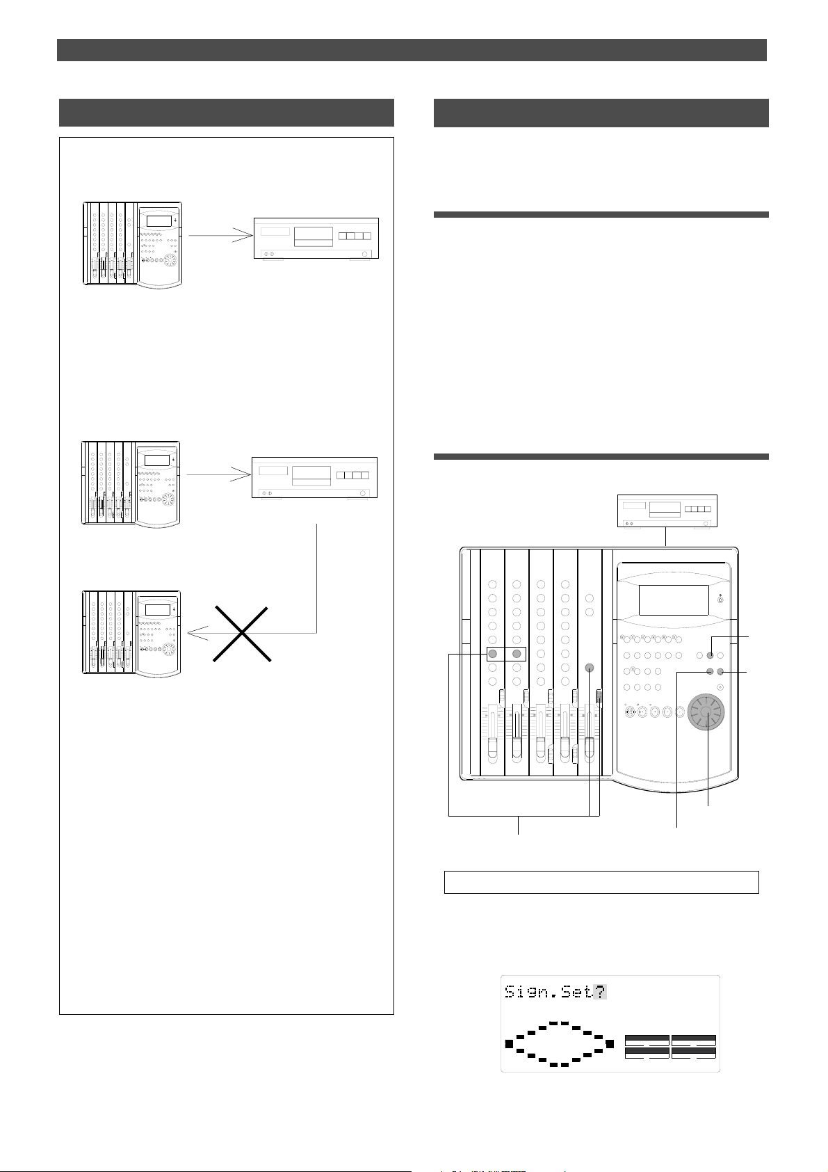
Saving and Loading Song Data
Remember this!
• Set the DAT recording mode to 32kHz/SP mode to save data
recorded on a disk formatted in Normal mode.
FD-4
EQ
EQ
Save
Data recorded on a disk in
Normal mode
• You cannot load data with a different sampling rate.
For example, if you save data recorded in Normal mode to a
DAT tape, then load it back to the FD-4, you will be unable to load
the data if the load destination disk has been formatted in
Mastering mode 1 or 2 (sampling rate: 44.1kHz), and vice versa.
FD-4
EQ
EQ
Save
Record mode: 32kHz/SP mode
DA T
Record mode: 32kHz/SP mode
DA T
Saving song data
In this example, song data on all tracks (4 Real tracks + 2
Additional tracks) of Program 1 is saved to a DAT tape.
Preparing a DA T machine
• Turn the power on to the DAT machine and insert a DAT
tape into the DAT.
• Check to see if the write-protect tab is closed on the DAT
tape so the machine can record.
• Rewind the tape to the beginning, if necessary.
• Set the recording mode of the DAT so that it will record
digital signal via the optical connector. If the data has been
recorded on the disk in Normal mode, set the recording mode
of the DAT to 32kHz/SP mode. Refer to the instruction manual
that comes with the DAT machine for other settings.
Operation on the FD-4
Use the “Save PGM ?” menu in SETUP mode to execute the
save operation.
Data recorded on a disk in
Normal mode
FD-4
EQ
EQ
Load
Disk in Mastering 1 or Mastering 2
• Even with the same sampling rate...
Assume that you recorded Real tracks and Additional tracks on the
disk in Mastering mode 1, saved them to a DA T tape, then loaded
them back to a disk in Mastering mode 2.
The FD-4 will load the data normally since Mastering mode 1 and
Mastering mode 2 use the same sampling rate. However, since
the load destination is a disk in Mastering mode 2, you cannot record
data to Additional tracks. That is, you were formerly able to record
Additional tracks in real-time on the disk in Mastering mode 1, but
now you cannot. If the original disk is in Mastering mode 2 and the
load destination disk is in Mastering mode 1, the situation will be
reversed. You could not record data on Additional tracks, but now
you can.
Remember that whether you can record Additional tracks depends
on the disk recording mode. Refer to the notes on recording mode
in the “Recording Preparation” chapter.
EQ
EQ
2, 5
Knobs and switches for monitoring
The gray area in the display illustration indicates it is flashing.
1.Press the SETUP key while the FD-4 is stopped.
The FD-4 enters SETUP mode and displays the first
hierarchy of the menu previously selected.
The [Sign. Set ?] menu appears in default.
3, 4, 6, 7
SETUP
1
8
SYNC OUT
CLK
AUTO A.PUNCH
DRIVE
SCSI
77
Page 78
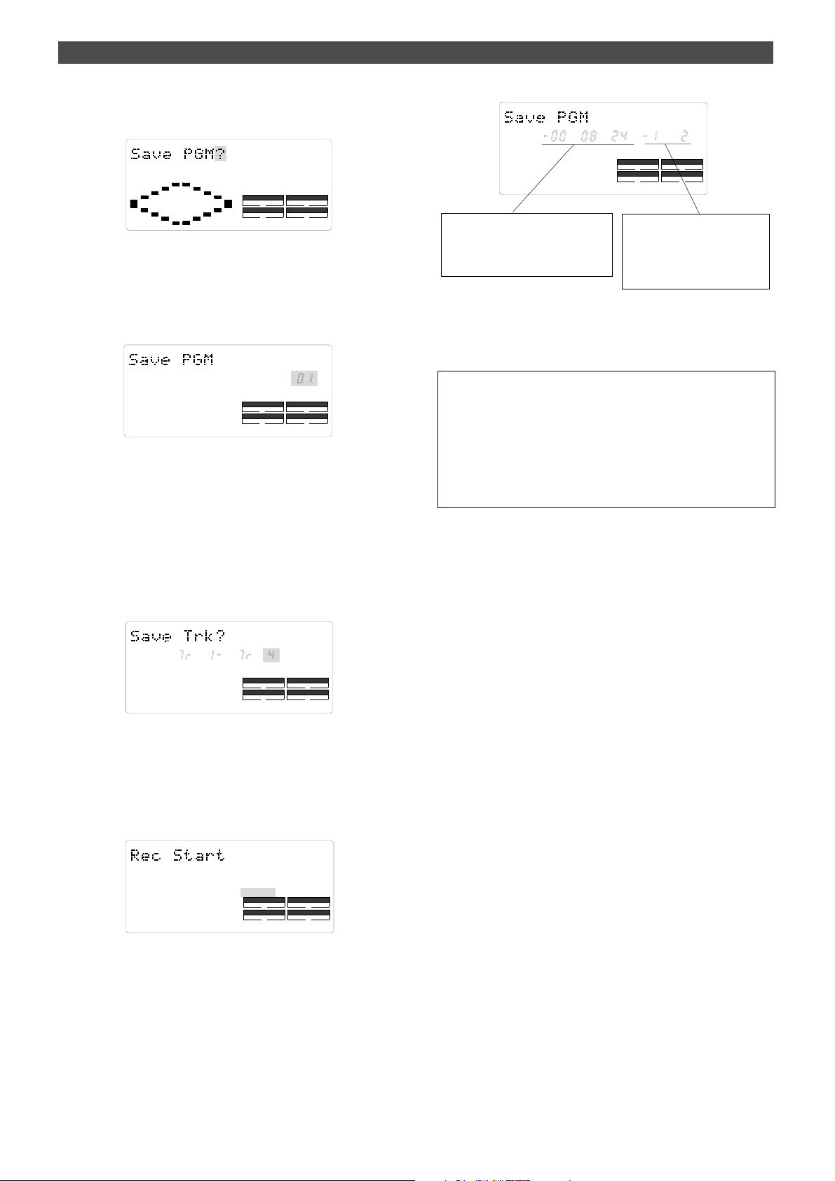
Saving and Loading Song Data
2.Use the JOG dial to display [Save PGM ?].
[?] flashes in the first hierarchy of the [Save PGM ?] menu.
SETUP
SYNC OUT
CLK
AUTO A.PUNCH
DRIVE
SCSI
3.Press the EXECUTE/YES key.
[?] stops flashing, and the Program number flashes.
This number indicates the program that was selected
before the FD-4 entered SETUP mode.
If multiple Programs exist, you can select the desired
Program in the next step.
SETUP
PGM
SYNC OUT
CLK
AUTO A.PUNCH
DRIVE
SCSI
4.Use the JOG dial to select the desired Program.
Select [01] (Program number 1) in this example.
You cannot select other numbers if only one Program
exists.
REMAIN
This area indicates a negative value of
total duration taken to save data (tracks
1–6), which increments as the save operation progresses.
SETUP
SMH
SYNC OUT
CLK
AUTO A.PUNCH
DRIVE
SCSI
This area indicates the tracks of
data currently saved. In this example, tracks 1 and 2 are being
saved. This will change to 3 and 4,
then 5 and 6.
When the save operation is complete, [COMPLETED !] lights
up on the display, and FD-4 stops. Stop recording on the
DAT machine.
You can monitor the data using the following methods, in addition to using the headphones connected to the DA T machine.
• Monitor selector [MON]
• T urning the MON knobs for channels 1 and 2 toward [TRK 1]
and [TRK 2] respectively
• T urning the MASTER knob in the monitor section
5.Press the EXECUTE/YES key.
The FD-4 displays the track selection for the save
operation, and [4] flashes. The next step allows you to
select whether you wish to save tracks 1–4 or 1–6. (The
following figure indicates tracks 1–4.)
SETUP
SYNC OUT
CLK
AUTO A.PUNCH
DRIVE
SCSI
6.Select the tracks to save using the JOG dial.
Rotating the JOG dial causes [4] and [6] to flash
alternately. In this example, select [6] to save data on all
tracks including the Additional tracks.
7.Press the EXECUTE/YES key.
[Rec Start] appears and [SURE ?] flashes.
SETUP
?
SURE
SYNC OUT
CLK
AUTO A.PUNCH
DRIVE
SCSI
9.Press the STOP button or the EXIT/NO key.
[COMPLETED !] disappears, the Program of the data you
saved to the DAT is selected, and the ABS Time Base
appears.
8.Start recording on the DAT machine, then press the
EXECUTE/YES key.
The display changes as follows, and the save operation is
in progress.
The pilot signal (beep sound), tracks 1 and 2, 3 and 4,
and 5 and 6 will be saved to the DAT tape sequentially, in
this order. During the save operation, the level meters 1
and 2, and L and R on the FD-4 indicate the output levels.
78
Page 79
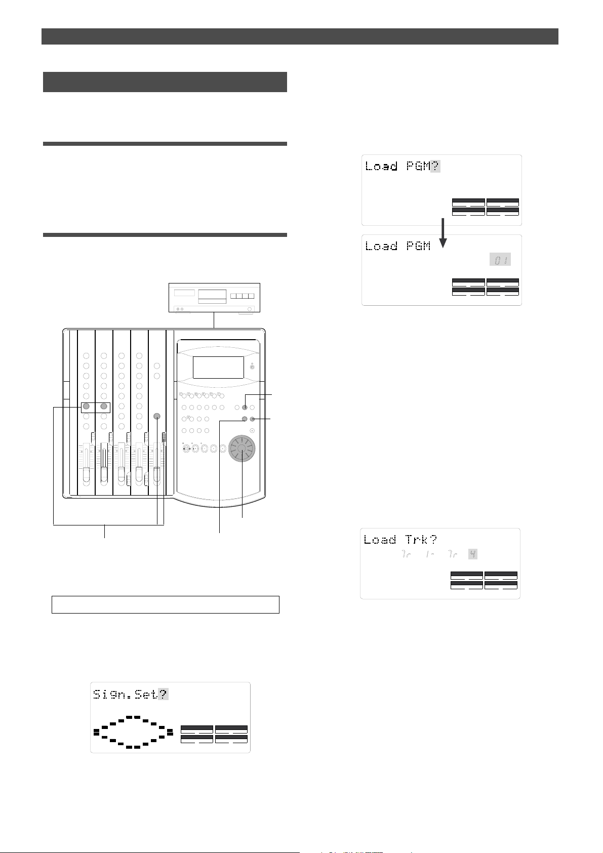
Saving and Loading Song Data
Loading song data
You can load the data from DAT to the SCSI disk of the FD-4.
Preparing a DA T machine
• Turn on the power to the DAT machine, and insert the tape
that includes the data you wish to load.
• Locate a point slightly before the pilot signal recorded at the
beginning of the data.
Operation on the FD-4
Use the “Load PGM ?” menu in SETUP mode to execute the
load operation. This menu can be found before the “Save
PGM ?” menu.
EQ
EQ
1
8
2.Turn the JOG dial to display [Load PGM ?], then press the
EXECUTE/YES key.
[?] stops flashing, and the Program number flashes.
This number indicates the program that is selected on
the load destination disk. If multiple Programs exist, you
can select the desired Program in the next step.
SETUP
SETUP
DRIVE
DRIVE
SCSI
PGM
SCSI
SYNC OUT
CLK
AUTO A.PUNCH
SYNC OUT
CLK
AUTO A.PUNCH
3.Use the JOG dial to select the desired Program.
You can select [01] or [02] if only one Program exists on
the disk.
If you select [02], [PGM] and [New] flash alternately.
This means that you can set up a new Program. If you do
not wish to lead data to Program 1, select [02] to
automatically create a new Program 2 on the disk, and
Program 2 will be selected as the destination. (In the same
way, if Programs 1–4 exist and you select [05], [New]
flashes. That is, if you select the next largest Program
number, [New] flashes.)
2, 5
Knobs and switches for monitoring
The gray area in the display illustration indicates it is flashing.
1.Press the SETUP key when the FD-4 is stopped.
The FD-4 enters SETUP mode, and the first hierarchy of
the menu previously selected appears on the display.
The [Sign Set ?] menu appears in default.
3, 4, 6, 7
SETUP
SYNC OUT
CLK
AUTO A.PUNCH
DRIVE
SCSI
4.Press the EXECUTE/YES key.
The FD-4 displays the track selection for the load
operation, and [4] flashes. The next step allows you to
select whether you wish to save tracks 1–4 or 1–6. (The
following figure indicates tracks 1–4.)
SETUP
SYNC OUT
CLK
AUTO A.PUNCH
DRIVE
SCSI
5.Select tracks to load using the JOG dial.
Rotating the JOG dial causes [4] and [6] to flash
alternately. In this example, select [6] to load data on all
tracks, including the Additional tracks.
If you select [4], data from tracks 1–4 will be loaded.
6.Press the EXECUTE/YES key.
The load destination Program and track data to be loaded
will be confirmed. The FD-4 displays an illuminated
DIGITAL indicator and a flashing [SURE ?] message.
A flashing DIGITAL indicates that the FD-4 is not
receiving digital signals from the DAT correctly.
Check the DAT setting and cable connections.
79
Page 80
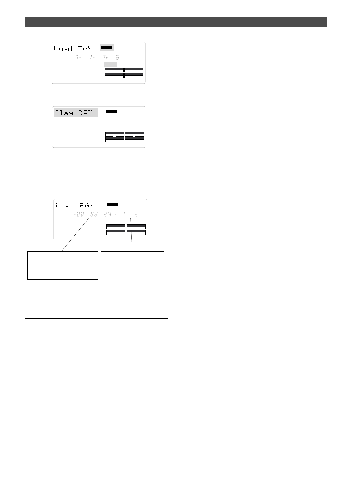
Saving and Loading Song Data
DIGITAL
SETUP
SURE ?
SYNC OUT
CLK
AUTO A.PUNCH
DRIVE
SCSI
7.Press the EXECUTE/YES key again.
[Play DAT !] appears on the display.
DIGITAL
SETUP
SYNC OUT
CLK
AUTO A.PUNCH
DRIVE
SCSI
8.Start playing the DAT machine.
When the saved pilot signal is played, the load operation
starts automatically. The duration for the load operation
appears as a negative value and increments as the opera
tion progresses. The tracks being loaded also appear on
the display.
DIGITAL
REMAIN
SETUP
SMH
SYNC OUT
CLK
AUTO A.PUNCH
DRIVE
SCSI
This area indicates a negative value of
the total duration required to load data,
which counts up as the load operation
progresses.
This area indicates the tracks of
currently-loaded data. In this example, tracks 1 and 2 are being
loaded. This will change to 3 and 4,
then 5 and 6.
During the load operation, the LEDs of the RECORD TRK
select keys 1/L and 2/R flash, and the level meters for
tracks 1 and 2, and L and R reflect the levels.
You can monitor the data using the following methods:
• Using the monitor selector [MON]
• Turning the MON knobs for channels 1 and 2 toward [TRK 1] and
[TRK 2] respectively
• Turning the MASTER knob in the monitor section
When the save operation is complete, [COMPLETED !] lights
up on the display, and FD-4 stops. Stop playing the DAT
machine.
9.Press the STOP button or the EXIT/NO key.
[COMPLETED !] disappears, the Program for the data you
loaded is selected, and the ABS Time Base appears.
80
Page 81
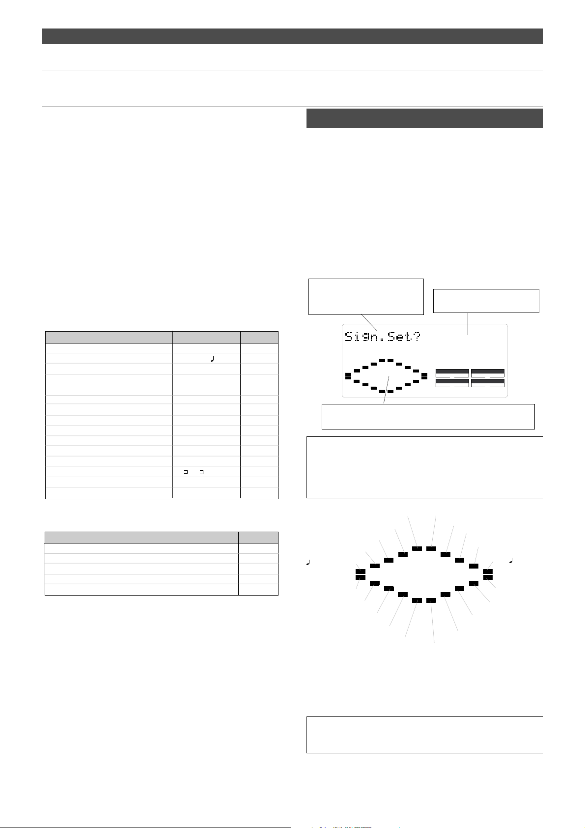
Changing the Initial setting (SETUP mode)
Changing the Initial Settings
SETUP mode of the FD-4 offers the “Changing the initial
settings” menus that configure the operating environment
of the FD-4, and the “Execution” menus that execute certain operations, such as save and load.
The “Changing the initial settings” menus include 16 parameters as shown in Table-1 below. These parameters were
set before the unit was shipped from the factory (These
values are called “initial settings.”). Modifying these settings allows you to change the operating environment of
the FD-4.
Also, as shown in Table-2, the “Execution” menus include
five items: Title Edit?, Del. PGM?, Load PGM?, Save PGM?,
and Format?, which you can execute by selecting the corresponding SETUP menu. This chapter explains how to use
the “Changing the initial settings” menus shown in Table-
1. For more information on the “Execution” menus, refer to
the corresponding pages in the “Reference page” column
in Table-2.
<Table-1> “Changing the initial settings” menus
Parameters Default setting
“Setting a time signature” 001 BAR 4/4 82
“Setting a tempo” 001 BAR1 120 83
“Setting the Metronome function” OFF 85
“Setting a preroll value” 00 85
“Setting MIDI sync output signal” CLK (Clock) 86
“Setting an MTC frame rate” 25 frame 87
“Setting an MTC offset value” 00h59m57s00f00sf 87
“Setting Offset mode” ABS 88
“Setting the Slave mode” OFF 88
“Setting the Slave type” Vari 89
“Setting the Record Protect function” OFF 90
“Setting digital input tracks” L-, r- (no assign) 91
“Setting digital output tracks” L- , r- (
“Setting BAR/BEAT resolution mode” OFF 92
“Setting the MIDI device number” 00 93
<Table-2> “Execution” menu
Items
Editing a Program title 38
Deleting a Program 39
Saving song data to an external DAT 77
Loading song data from an external DAT 79
Formatting an external SCSI disk 6-8
ST OUT)
Refer page
92
Refer page
Selecting SETUP mode
Follow the steps below to select the desired SETUP menu in
SETUP mode.
1.While the FD-4 is stopped, press the SETUP key on the
control panel.
Pressing the SETUP key causes the FD-4 to enter SETUP
mode. The FD-4 displays the first hierarchy level of the
SETUP menu you selected before you turned off the power.
At this time, the menu graphics appear as shown below.
The flashing menu indicator is the currently-selected
menu. Turning the JOG dial will select a different menu
and the corresponding menu indicator will flash.
The following diagram shows the position of each menu.
The title of the SETUP menu appears. You can select a different
menu via the JOG dial.
This indicates the position of the SETUP menu. Selecting a menu
via the JOG dial will move the flashing cursor.
<Note>
With the factory initial settings, or when you turn on the power again after
you format an external SCSI disk, “Sign. Set? (Setting a time signature)”
appears. Otherwise, the first hierarchy level of the previously-selected
SETUP menu appears.
Load PGM ? menu
Device ID ? menu
Resolu ? menu
Digi. out ? menu
Digi. in ? menu
Rec Protect ? menu
2.Select the desired menu using the JOG dial, then press the
EXECUTE/YES key.
The FD-4 displays the second hierarchy level of the
selected SETUP menu, where you can set parameters.
(Refer to the next page for more information.)
(SETUP Mode)
Format ? menu
Save PGM ? menu
Slave Type? menu
Slave Mode? menu
This lights up when the FD-4
enters SETUP mode.
SETUP
SYNC OUT
CLK
AUTO A.PUNCH
Sign. Set ? menu
Tempo Set ? menu
Ofset Mode ? menu
DRIVE
SCSI
Title Edit ? menu
Del PGM ? menu
Click ? menu
Sync Out? menu
Frame Rate ? menu
Mtc Offset ? menu
Preroll ? menu
T o exit SETUP mode, press the STOP button or the EXIT/NO key . Each
time you press one of these keys, the FD-4 returns to the previous hierarchy level of the menu, and finally exits SETUP mode.
81
Page 82

Changing the Initial setting (SETUP mode)
Setting a time signature
Using the “Setting a time signature” menu, you can set a
time signature of a given measure on the internal programmable Tempo Map. For example, you can specify “4/4 for
the first and second measures, and 2/4 from the third measure.” Setting a time signature and tempo will create a
Tempo Map, which allows the FD-4 to manage a song using
the BAR/BEAT/CLK Time Base. You can also use the Metronome function. The time signature and tempo setting are
required when MIDI clock & Song Position Pointer are output to an external sequencer.
• Initial setting: 4/4 for bar 001 (not specified for 002 and later.)
• Setting range of measures: 001 – 999
• Setting range of time signatures: 1/4, 2/4, 3/4, 4/4, 5/4, 1/8, 3/8, 5/8,
6/8, 7/8, 8/8, -/- (delete)
• Max. setting points: 64 points
* You can set time signatures for each Program individually.
* The settings can be saved and loaded as part of the song data.
* The settings are maintained after you turn off the power to the unit.
Storing a time signature
1.Select a Program for which to set a time signature.
Refer to “Using the Program Change function” on page
37 for information on selecting a Program.
2.Press the SETUP key, use the JOG dial to select the
“Sign. Set?” menu, then press the EXECUTE/YES key.
The indication changes to “Sign. Chk” and the current
time signature appears. The initial setting is “001BAR 4
4” (4/4 for the first measure).
SETUP
SYNC OUT
CLK
BAR
SYNC OUT
CLK
At this time, rotating the JOG dial clockwise enables you
to check the current time signatures in sequence.
With the initial setting, time signatures after the first
measure are all “---BAR-
-.” This means that a time
signature of 4/4 applies to all measures.
3.Press the EXECUTE/YES key.
The indication changes to “Sign.Edit” and “001 (measure)”
of “001BAR”4
4” flashes. You can enter any time
signature here.
DRIVE
AUTO A.PUNCH
SETUP
DRIVE
AUTO A.PUNCH
SCSI
SCSI
• Rotate the JOG dial to enter the desired measure number.
If you wish to keep the initial setting for the first measure, enter 002. If you
try to enter any number other than 001, the time signature indicator shows
“- -..” This means that no time signature is set for any measures other
than the first measure. T o change the time signature for the first
measure, follow the steps below, without entering any other measure
number.
• Press the HOLD/> key, the REWIND button, or the F FWD
button to display flashing “--” of “-
-” and enter the time
signature using the JOG dial.
The following measure numbers and time signatures can
be entered via the JOG dial.
Measures 001–999, selection of All Clear? indication
“All Clear?” means that data in its entirety will be
cleared. This is used to initialize the parameter. (Re
fer to “Clearing stored time signature/tempo data.”)
Time signatures 1/4, 2/4, 3/4, 4/4, 5/4, 1/8, 3/8, 5/8, 6/8, 7/8, 8/8, --
“--” means no time signature assigned, and is used
to delete time signature data. (Refer to “Modifying
(or deleting) stored time signatures” for more
information.)
<Note>
You cannot assign “- -” to measure 001.
4. Press the EXECUTE/YES key whenever you enter a pair of
measure/time signature values.
Repeat this step to specify the necessary time signature
for the measures.
T o cancel the setting operation, or to exit SETUP mode after storing
data, press the STOP button or the EXIT/NO key. Each time you
press one of these keys, the FD-4 returns to the previous hierarchy
level of the menu, and finally exits SETUP mode.
Modifying (or deleting) stored time signatures
1.Repeat steps 1–3 described in the “Storing a time
signature” section to display “Sign.Edit.”
2.Press the HOLD/> key, the REWIND button, or the F FWD
button so that the flashing cursor is on the time signature
value.
3.Use the JOG dial to enter a new value.
Entering “--” deletes the existing data. Note that you
cannot enter “--” for measure 001.
4.Press the EXECUTE/YES key.
T o cancel the setting operation, or to exit SETUP mode after storing
data, press the STOP button or the EXIT/NO key. Each time you
press one of these keys, the FD-4 returns to the previous hierarchy
level of the menu, and finally exits SETUP mode.
82
BAR
SETUP
SYNC OUT
CLK
AUTO A.PUNCH
<Caution>
DRIVE
SCSI
If modifying or deleting the stored time signature causes the bar/beat
setting for the tempo specified in the “Setting a tempo” menu to disappear, the tempo setting will also be automatically erased.
Page 83
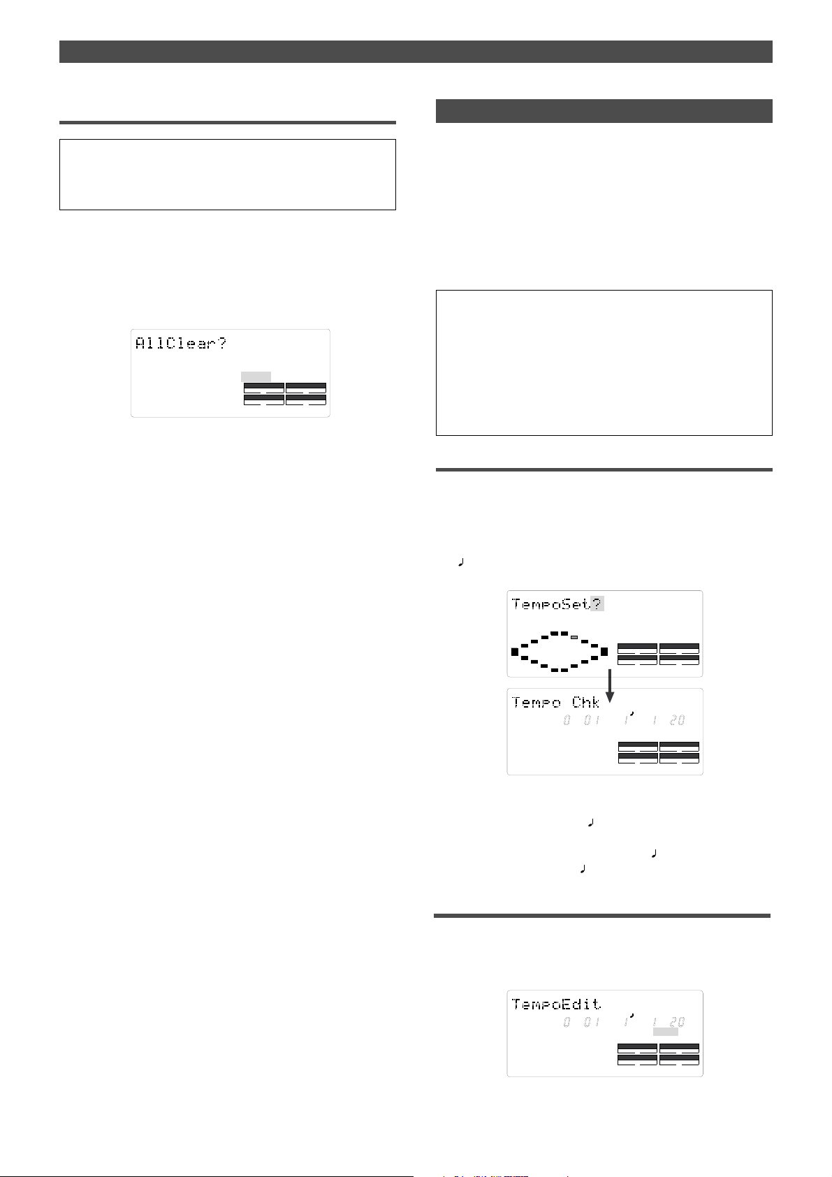
Changing the Initial setting (SETUP mode)
Clearing all time signature and tempo settings
<Caution>
Using this function will erase not only the time signature setting but
also the tempo data specified in the “Setting a tempo” menu described in the next section.
1.Repeat steps 1–3 described in the “Storing a time
signature” section to display “Sign.Edit.”
2.While the measure number is flashing, turn the JOG dial
counter-clockwise to select “All Clear?.”
When “All Clear?” appears, “SURE?” flashes, and you can
clear the time signature and tempo data in the next step.
SETUP
?
SURE
SYNC OUT
CLK
AUTO A.PUNCH
To cancel the All Clear operation, press the STOP button
or the EXIT/NO key now. Each time you press one of these
keys, the FD-4 returns to the previous hierarchy level of
the menu, and finally exits SETUP mode.
3.Press the EXECUTE/YES key.
The stored time signature and tempo data in its entirety
are cleared, and the initial settings are restored.
DRIVE
SCSI
Setting a tempo
The “Setting a tempo” menu enables you to specify a tempo
at a given point in a song that already has a time signature
setting. For example, you can specify a tempo of 150 to the
third beat of the 12th measure.
Time signature and tempo settings make a Tempo Map,
which is used by the FD-4 to manage the song using the
BAR/BEAT/CLK Time Base, and enable the Metronome function. Tempo settings as well as time signature settings are
required when you wish to output MIDI clock and Song
Position Pointer to an external sequencer.
• Initial setting: bar 001, beat 1: 120
• Setting range of measures: Determined by the time signature
setting.
• Setting range of beats: Determined by the time signature setting.
• Setting range of tempo: 30–250/quarter note, --- (delete)
• Max. setting points: 64 points
* You can set the tempo for each Program individually.
* The settings can be saved and loaded as part of song data.
* The settings are maintained after you turn off the power to the unit.
Checking the stored tempo setting
1.Select a Program to check the tempo setting for.
Press the SETUP key , use the JOG dial to select the “Tempo
Set?” menu, then press the EXECUTE/YES key.
Indication on the display changes as shown below, and
the current tempo appears. The initial setting is [001 BAR
1
TEMPO 120]. This means that a tempo for the first
beat of the first measure is set to 120.
SETUP
DRIVE
SETUP
TEMPO
DRIVE
AUTO A.PUNCH
SCSI
SCSI
BAR
SYNC OUT
CLK
AUTO A.PUNCH
SYNC OUT
CLK
2.Rotate the JOG dial clockwise.
You can view the current tempo values in sequence.
Tempo value [- - - BAR -
TEMPO - - -] means that no
tempo values are specified after the current setting.
With the initial setting, [001 BAR 1
followed by [- - - BAR -
TEMPO - - -].
TEMPO 120] is
Storing a tempo value
3.Press the EXECUTE/YES key.
The display indicates “Tempo Edit” and “TEMPO” flashes.
(See the figure below.) This means that you can enter a
value now.
BAR
SETUP
SYNC OUT
CLK
AUTO A.PUNCH
TEMPO
DRIVE
SCSI
83
Page 84

Changing the Initial setting (SETUP mode)
4.Press the HOLD/> key, the REWIND button, or the F FWD
button to move the flashing cursor to the desired edit
location, and use the JOG dial to enter the bar/beat/tempo
information to be stored.
Pressing the HOLD/> key or the F FWD button repeatedly
will move the flashing cursor from TEMPO to BAR and to
, then returns to TEMPO.
Pressing the REWIND button repeatedly will move the
cursor in the opposite direction.
The bar and beat settings for the time signatures deter
mine the setting range of bar and beat settings for the
tempo. You can specify a tempo between 30 and 250 per
quarter note.
The indication [---] means “no tempo,” which is used to
delete a tempo setting.
When you turn the JOG dial, [---] appears for the bars and
beats for which no tempo has been set.
5.Press the EXECUTE/YES key.
The display shows the stored bar/beat/tempo, then
returns to the Tempo Edit indication (as shown in step 3).
6.Repeat steps 3-5 to store necessary tempo data.
For example, if you specify tempo values in the song with
[001 BAR 4
Map includes the settings shown in the table below.
4] and [005 BAR 3 4] settings, the Tempo
Modifying (or deleting) stored tempo settings
1.Repeat steps 1–3 described in the “Storing a tempo value”
section to display “Tempo Edit?”
2.Press the HOLD/> key, the REWIND button, or the F FWD
button so that the flashing cursor is on the measure
num ber. T urn the JOG dial to select bar/beat to edit or
delete.
3.Press the HOLD/> key, the REWIND button, or the F FWD
button so that the flashing cursor is on the TEMPO number.
4.Use the JOG dial to enter a new value.
Entering “--” deletes the data at the selected bar/beat.
5.Press the EXECUTE/YES key.
6.Press the STOP button or the EXIT/NO key repeatedly to
exit SETUP mode.
4
4
Tempo=120
3
4
T empo=60
Time signature setting
001 BAR 4 4
005 BAR 3
4
T empo=90
Tempo Map
001 BAR 1
003 BAR 1
005 BAR 3
007 BAR 2
T empo=120
Tempo setting
TEMPO 120
TEMPO 90
TEMPO 60
TEMPO 120
84
Page 85

Changing the Initial setting (SETUP mode)
Setting the Metronome function
“Setting the Metronome function” menu allows you to determine whether or not the FD-4 outputs a metronome
sound from Real track 4 during playback or recording.
Turning the Metronome function on enables you to record
your performance while playing the instrument accompanying the metronome sound.
<Note>
Since Real track 4 outputs the metronome sound when this function
is turned on, you cannot play the audio recorded on this track. Also,
do not record any data on track 4.
The FD-4 can output the metronome sound even from an unrecorded area (outside of the range from ABS 0 to ABS REC END) on
track 4.
• Initial setting: oFF
• Option: oFF, on
* You can turn the function on and off for each Program individually.
* The settings can be saved and loaded as part of the song data.
* The settings are maintained after you turn off the power to the unit.
Setting the Metronome function
1.While the FD-4 is stopped, press the SETUP key to enter
SETUP mode.
2.Turn the JOG dial to select [Click
the EXECUTE/YES key.
The current setting (oFF or on) appears on the display.
Pressing the EXECUTE/YES key lights up the flashing [?]
character steadily; the current setting flashes. The initial
setting is [oFF] as shown below.
?] (? flashes.), then press
SETUP
CLK
SYNC OUT
DRIVE
AUTO A.PUNCH
SETUP
SCSI
Setting a preroll value
The FD-4 features the Preroll function that enables you to
locate a position a few seconds prior to a specified locate
point. The “Setting a preroll value” menu allows you to set
the preroll time (in seconds).
The Preroll function is convenient when you wish to monitor the audio data from a point slightly before the locate
point.
• Initial setting: 00 second
• Setting range of preroll time: 00-10 seconds in one second steps
* You can set the value for each Program individually.
* The settings can be saved and loaded as part of the song data.
* The settings are maintained after you turn off the power to the unit.
Locate point (stored in the
This point is actually located.
This point is located if the
current position is before
the locate point.
Preroll time (before the locate point)
can be set between 00 and 10 seconds.
Setting a preroll time
1.While the FD-4 is stopped, press the SETUP key to enter
SETUP mode.
2.Turn the JOG dial to select [Preroll ?] (? flashes.), then press
the EXECUTE/YES key.
The current preroll time setting appears on the display.
Pressing the EXECUTE/YES key lights up the flashing [?]
character steadily; the current setting flashes. The initial
setting is [00] as shown below.
memory key)
This point is located if the current position is after the locate
point.
SETUP
S
SYNC OUT
CLK
AUTO A.PUNCH
DRIVE
SCSI
SYNC OUT
CLK
AUTO A.PUNCH
DRIVE
SCSI
3.Turn the JOG dial to select on or oFF .
Selecting [on] will enable the output of the metronome
sound. Selecting [oFF] (initial setting) will disable the
metronome output.
4.Press the EXECUTE/YES key.
The display shows the selection (on or oFF), then returns
to the indication in step 2.
T o cancel the setting operation, or to restore a setting obtained prior
to the EXECUTE/YES key press, press the STOP button or the
EXIT/NO key. Each time you press one of these keys, the FD-4
returns to the previous hierarchy level of the menu, and finally exits
SETUP mode and displays the previous Time Base.
SETUP
S
SYNC OUT
CLK
AUTO A.PUNCH
DRIVE
SCSI
3.Turn the JOG dial to enter a desired preroll time value.
You can set a value in one-second increments. Rotating
the JOG dial clockwise increases the value, and rotating it
counter-clockwise decreases the value.
4.Press the EXECUTE/YES key.
The display shows the value, then returns to the
indication that appeared in step 2.
T o cancel the setting operation, or to restore the setting obtained prior to
the EXECUTE/YES key press, press the STOP button or the EXIT/NO
key. Each time you press one of these keys, the FD-4 returns to the
previous hierarchy level of the menu, and finally exits SETUP mode and
displays the previous Time Base.
85
Page 86
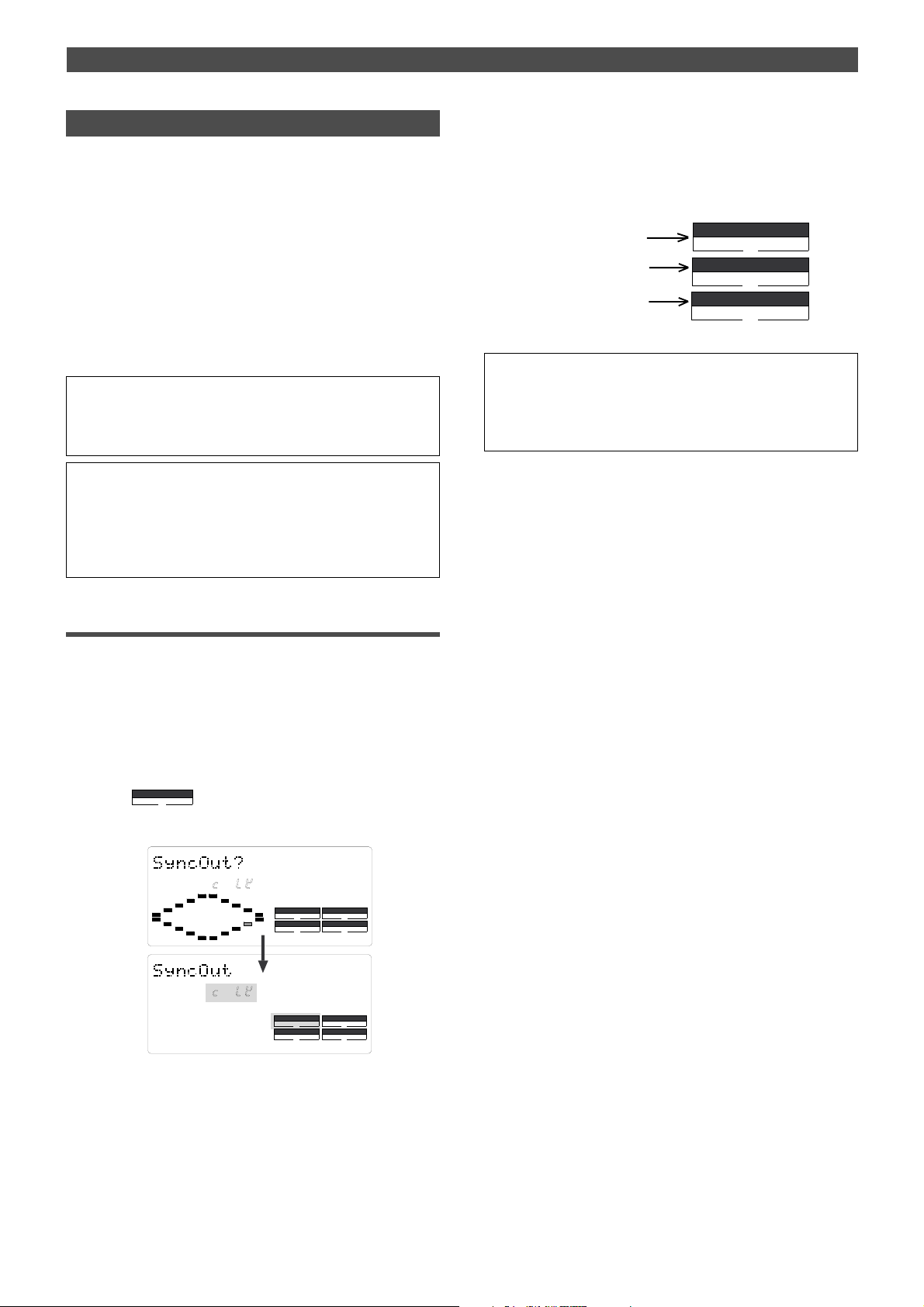
Changing the Initial setting (SETUP mode)
Setting MIDI sync output signal
The “Setting MIDI sync output signal” menu enables you to
select the type of MIDI sync signals output from the MIDI
OUT connector on the rear panel of the FD-4 to an external
MIDI device.
The options are MIDI clock & Song Position Pointer, or MTC
(MIDI time code). Select an appropriate option depending
on the type of signal supported by the connected MIDI device.
If you select MIDI clock & Song Position Pointer, first you
need to set the time signatures and tempo as described
previously. If you select MTC, you first need to set the MTC
frame rate, the MTC offset time, and the MTC offset mode
as described later.
<Note>
The FD-4 can output MIDI clock & Song Position Pointer, and MTC
even from an unrecorded area (outside of the range of ABS 0 to
ABS REC END).
• Initial setting: CLK (clock & Song Position Pointer)
• Option: CLK (clock & Song Position Pointer),
MIDI (MIDI time code), OFF (no output)
* You can set the parameters for each Program individually.
* The settings can be saved and loaded as part of the song data.
* The settings are maintained after you turn off the power to the unit.
4.Press the EXECUTE/YES key.
The selected MIDI sync signal type is stored, and the FD4 returns to the display with the flashing [?] indicator as
shown in step 2.
Each option appears on the display as follows.
When CLK is selected:
When MTC is selected:
When OFF is selected:
SYNC OUT
CLK
SYNC OUT
MTC
SYNC OUT
T o cancel the setting operation, or to restore a setting obtained prior
to the EXECUTE/YES key press, press the STOP button or the
EXIT/NO key. Each time you press one of these keys, the FD-4
returns to the previous hierarchy level of the menu, and finally exits
SETUP mode and displays the previous Time Base.
Setting MIDI sync signal
1.While the FD-4 is stopped, press the SETUP key to enter
SETUP mode.
2.Rotate the JOG dial to select [Sync Out ?] (? flashes.), then
press the EXECUTE/YES key.
The currently-selected MIDI sync signal type appears on
the display.
Press the EXECUTE/YES key to turn off the flashing [?]
indication. The MIDI sync signal type indication flashes,
and the indicator flashes indicating the SYNC
OUT setting.
The initial setting is [cLk] as shown below.
SYNC OUT
CLK
SETUP
SYNC OUT
CLK
AUTO A.PUNCH
SETUP
SYNC OUT
CLK
AUTO A.PUNCH
DRIVE
DRIVE
SCSI
SCSI
3.Turn the JOG dial to select the desired MIDI sync signal.
Setting this parameter to [cLK] (initial setting) will select
MIDI clock & Song Position Pointer.
Setting the parameter to [MTC] will select MIDI time code.
With the [oFF] setting, no MIDI sync signal will be output.
86
Page 87

Changing the Initial setting (SETUP mode)
Setting an MTC frame rate
The “Setting an MTC frame rate” menu enables you to set
the frame rate for MTC output from the MIDI OUT connector of the FD-4 to an external MIDI device. If you have already set the type of MIDI sync output signal to [MTC], you
need to set the frame rate. Use the frame rate of MTC received by the external MIDI device (or sequence software).
• Initial setting: 25 frames
• Setting range of frame rate: 24, 25, 30df, 30nd
* You can set the value for each Program individually.
* The settings can be saved and loaded as part of the song data.
* The settings are maintained after you turn off the power to the unit.
Setting an MTC frame rate
1.While the FD-4 is stopped, press the SETUP key to enter
SETUP mode.
2.Turn the JOG dial to select [Frame Rate (?)] (“e” and “?”
flash alternately.), then press the EXECUTE/YES key.
The current frame rate setting appears on the display.
Press the EXECUTE/YES key to turn off the flashing [?]
character; the current setting flashes. The initial setting
of [25] flashes as shown below.
SETUP
F
SYNC OUT
CLK
AUTO A.PUNCH
DRIVE
SCSI
Setting an MTC offset value
The “Setting an MTC offset value” menu enables you to
specify an offset time value – the difference between the
time of MTC output from the FD-4 and the ABS 00m 00s
00f 00sf time. You need to specify this value if you have
selected [MTC] for the “Setting MIDI sync output signal”
menu.
With the initial setting of 00h 59m 57s 00f 00sf, for example, MTC of 59m 57s 00f 00sf is output at the ABS time
00m 00s 00f 00sf. You can also set an offset value from the
001 BAR 1
Refer to the next section for information on MTC Offset
mode.
• Initial setting: 00h 59m 57s 00f 00sf
• Setting range of offset time: 00h 00m 00s 00f 00sf – 23h 59m 59s
29f 99sf
* You can set the value for each Program individually.
* The settings can be saved and loaded as part of the song data.
* The settings are maintained after you turn off the power to the unit.
Setting an MTC offset
1.While the FD-4 is stopped, press the SETUP key to enter
SETUP mode.
2.Turn the JOG dial to select [Mtc Offset (?)] (“t” and “?”
flash alternately.), then press the EXECUTE/YES key .
The current offset value appears on the display. Pressing
the EXECUTE/YES key turns off the flashing [?] character,
and the value in seconds flashes.
You can enter a value at the flashing digit. The number
“57” of the initial setting [57s] flashes as shown below.
00 CLK value (bar/beat) on the Tempo Map.
SETUP
F
SYNC OUT
CLK
AUTO A.PUNCH
DRIVE
SCSI
3.Turn the JOG dial to enter the desired frame rate.
Rotating the JOG dial clockwise or counter-clockwise
displays available frame rates as an alternative.
4.Press the EXECUTE/YES key.
The selected frame rate is stored and the display returns
to the indication with a flashing [?] that appeared in step
2.
To cancel the operation, or to restore the setting obtained prior to
the EXECUTE/YES key press, press the STOP button or the EXIT/
NO key. Each time you press one of these keys, the FD-4 returns to
the previous hierarchy level of the menu, and finally exits SETUP
mode and displays the previous Time Base.
MTC OFFSET
SETUP
SMHFSF
SETUP
DRIVE
SCSI
MTC OFFSET
DRIVE
SCSI
SYNC OUT
CLK
AUTO A.PUNCH
SMHFSF
SYNC OUT
CLK
AUTO A.PUNCH
3.Use the HOLD/> key, the REWIND button, or the F FWD
button to move the flashing cursor, and turn the JOG dial to
enter the desired offset value.
Press the HOLD/> key or the F FWD button to move the
flashing cursor to the right, and press the REWIND
button to move it to the left. Turning the JOG dial
continuously will round up the number to the next digit.
For example, if you rotate the JOG dial on the seconds
digit up 59, turning the dial further will increase the
number on the digit of minute by one.
4.Press the EXECUTE/YES key.
The selected offset value is stored and the display
returns to the indication with the flashing [?] that
appeared in step 2.
87
Page 88

Changing the Initial setting (SETUP mode)
SETUP
DRIVE
AUTO A.PUNCH
SYNC OUT
CLK
SCSI
BAR
T o cancel the operation, or to restore the setting obtained prior to the
EXECUTE/YES key press, press the STOP button or the EXIT/NO
key . Each time you press one of these keys, the FD-4 returns to the
previous hierarchy level of the menu, and finally exits SETUP mode
and displays the previous Time Base.
<Note>
For example, if you set MTC Offset mode to [ABS] (see the next
section) and you wish to start the song from MTC’s 1h 00m 00s 00f,
you may wish to set a preroll of three seconds with an MTC offset of
00h 59m 57s 00f.
Setting Offset mode
If you have selected [MTC] in the “Setting Offset mode”
menu, you need to select MTC Offset mode. This menu enables you to determine whether the specified MTC is output at ABS 00h 00m 00s 00f or at 001 BAR 1
beat) of the Tempo Map.
<Note>
As an example, if you set MTC Offset mode to [ABS] and you wish to
start the song from MTC’s 1h 00m 00s 00f, you may want to set a
preroll of three seconds with MTC offset of 00h 59m 57s 00f.
If you select [BAR
] as the MTC Offset mode, a preroll of two measures is automatically set. Use 01h 00m 00s 00f; do not set a preroll
value.
<Note>
If you set Offset mode to [BAR ] and use MTC to synchronize
sequence software on the computer, the tempo of the sequencer
may sometimes slip gradually. This is because the tempo of the FD4 and the tempo of the software are slightly different even if both use
the same tempo. Some sequence software can read the tempo output from the FD-4 correctly. W e recommend that you use the tempo
of the FD-4 on the sequence software.
No such problems will occur if the sequence software synchronizes
the FD-4 via MIDI clock, instead of MTC.
• Initial setting: ABS 00h 00m 00s 00f
• Offset mode option: ABS (00h 00m 00s 00f), BAR
(001 BAR 1 )
* You can set the mode for each Program individually.
* The settings can be saved and loaded as part of the song data.
* The settings are maintained after you turn off the power to the unit.
Setting MTC Offset mode
1.While the FD-4 is stopped, press the SETUP key to enter
SETUP mode.
2.Turn the JOG dial to select [Offset Mode (?)] (“e” and “?”
flash alternately.), then press the EXECUTE/YES key .
The current offset mode appears on the display.
Pressing the EXECUTE/YES key to turn off the flashing [?]
character.
The Offset mode indicator flashes.
With the initial setting, [ABS 00h 00m 00s 00f] flashes as
shown below.
00 CLK (bar/
ABS
ABS
SETUP
SMHF
SETUP
DRIVE
DRIVE
SCSI
SCSI
SYNC OUT
CLK
AUTO A.PUNCH
SMHF
SYNC OUT
CLK
AUTO A.PUNCH
3.Use the JOG dial to select the desired Offset mode.
Rotating the JOG dial clockwise or counter-clockwise will
alternately show a flashing “AS 00h 00m 00s 00f” and
“001BAR 1
”.
If you select [ABS 00h 00m 00s 00f], the specified MTC
offset time is output at ABS 00h 00m 00s 00f.
If you select [001BAR 1
output at 001 BAR 1
ABS
SMHF
SYNC OUT
CLK
], the specified MTC offset time is
00 CLK of the Tempo Map.
SETUP
DRIVE
SCSI
AUTO A.PUNCH
4.Press the EXECUTE/YES key.
The selected offset mode is stored and the display
returns to the indication with flashing [e] and [?].
To cancel the operation, or to restore the setting obtained prior to
the EXECUTE/YES key press, press the STOP button or the EXIT/
NO key . Each time you press one of these keys, the FD-4 returns to
the previous hierarchy level of the menu, and finally exits SETUP
mode and displays the previous Time Base.
Setting the Slave mode
The “Setting the Slave mode” menu allows you to set Slave
mode of the FD-4 to on and off.
When Slave mode is turned on, the FD-4 will lock to MTC
input from the master device. The FD-4 can also sync to the
selected external sync signal if you select an appropriate
Slave type.
With this menu setting, you can set up a system in which
multiple FD-4s operate in sync or an FD-4 synchronizes to
a Fostex digital multitrack recorder, as well as the FD-4 locking to MTC output from the sequence software.
• Initial setting: oFF
• Option: on or oFF
* You can set the mode for each Program individually.
* The settings can be saved and loaded as part of song data.
* The settings are maintained after you turn off the power to the unit.
* The Program is automatically checked before the operation.
* The sampling rate is automatically checked before the operation.
88
Page 89
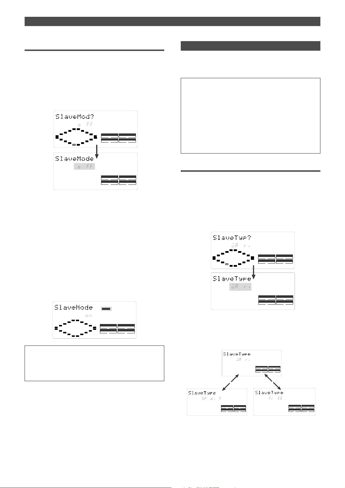
Changing the Initial setting (SETUP mode)
SETUP
DRIVE
AUTO A.PUNCH
SYNC OUT
CLK
SCSI
SETUP
DRIVE
AUTO A.PUNCH
SYNC OUT
CLK
SCSI
Turning Slave mode on and off
1.While the FD-4 is stopped, press the SETUP key to enter
SETUP mode.
2.Turn the JOG dial to select [Slave Mode (?)] (“e” and “?”
flash alternately), then press the EXECUTE/YES key.
The current slave mode appears on the display.
Pressing the EXECUTE/YES key turns off the flashing [?]
character, and the Slave mode indicator flashes.
With the initial setting, [oFF] flashes as shown below.
SETUP
SETUP
SETUP
DRIVE
DRIVE
SCSI
SCSI
SYNC OUT
CLK
AUTO A.PUNCH
SYNC OUT
CLK
AUTO A.PUNCH
3.Use the JOG dial to turn Slave mode on and off.
Rotating the JOG dial clockwise and counter-clockwise
alternates flashing [on] and [oFF].
Selecting [on] turns Slave mode on, and selecting [oFF]
turns Slave mode off.
4.Press the EXECUTE/YES key.
If you select [oFF], “e” and “?” flash alternately.
If you select [on], “e” and “?” flash alternately and [SLAVE]
flashes as shown below.
This means that the FD-4 has not locked to the sync
signal.
When the FD-4 locks to the sync signal from the master
device, [SLAVE] lights up steadily.
After you set Slave mode to [on], you need to select the
Slave type (type of sync signal) described in the next
section.
SLAVE
Setting the Slave type
The “Setting the Slave type” menu enables you to select the
type of external sync signal used when the FD-4 is set as a
slave to sync to an external device.
• Initial setting: VAri
• Option: VAri: The FD-4 synchronizes only to external MTC.
• SPdiF: The FD-4 locks to MTC, then synchronizes to incoming
S/PDIF digital signals.
• FrEE: The FD-4 locks to MTC, then synchronizes to the internal
clock.
* You can set the parameter for each Program individually.
* The settings can be saved and loaded as part of the song data.
* The settings are maintained after you turn off the power to the unit.
* The Program is automatically checked before the operation.
* The sampling rate is automatically checked before the operation.
Setting the Slave type (external sync signal)
1.While the FD-4 is stopped, press the SETUP key to enter
SETUP mode.
2.Turn the JOG dial to select [Slave Type (?)] (“e” and “?”
flash alternately), then press the EXECUTE/YES key.
The current Slave type appears on the display.
Pressing the EXECUTE/YES key turns off the flashing [?]
character, and the Slave type indicator flashes.
With the initial setting, [VAri] flashes as shown below.
SETUP
SETUP
DRIVE
DRIVE
SCSI
SCSI
SYNC OUT
CLK
AUTO A.PUNCH
SYNC OUT
CLK
AUTO A.PUNCH
SYNC OUT
CLK
AUTO A.PUNCH
DRIVE
SCSI
To cancel the operation, or to restore the setting obtained prior to
the EXECUTE/YES key press, press the STOP button or the EXIT/
NO key . Each time you press one of these keys, the FD-4 returns to
the previous hierarchy level of the menu, and finally exits SETUP
mode and displays the previous Time Base.
3.Use the JOG dial to select the desired Slave type.
Rotating the JOG dial clockwise and counter-clockwise
will cause the [VAri], [SPdiF], and [FrEE] indicators to flash
in sequence.
SETUP
DRIVE
SYNC OUT
CLK
AUTO A.PUNCH
SCSI
89
Page 90
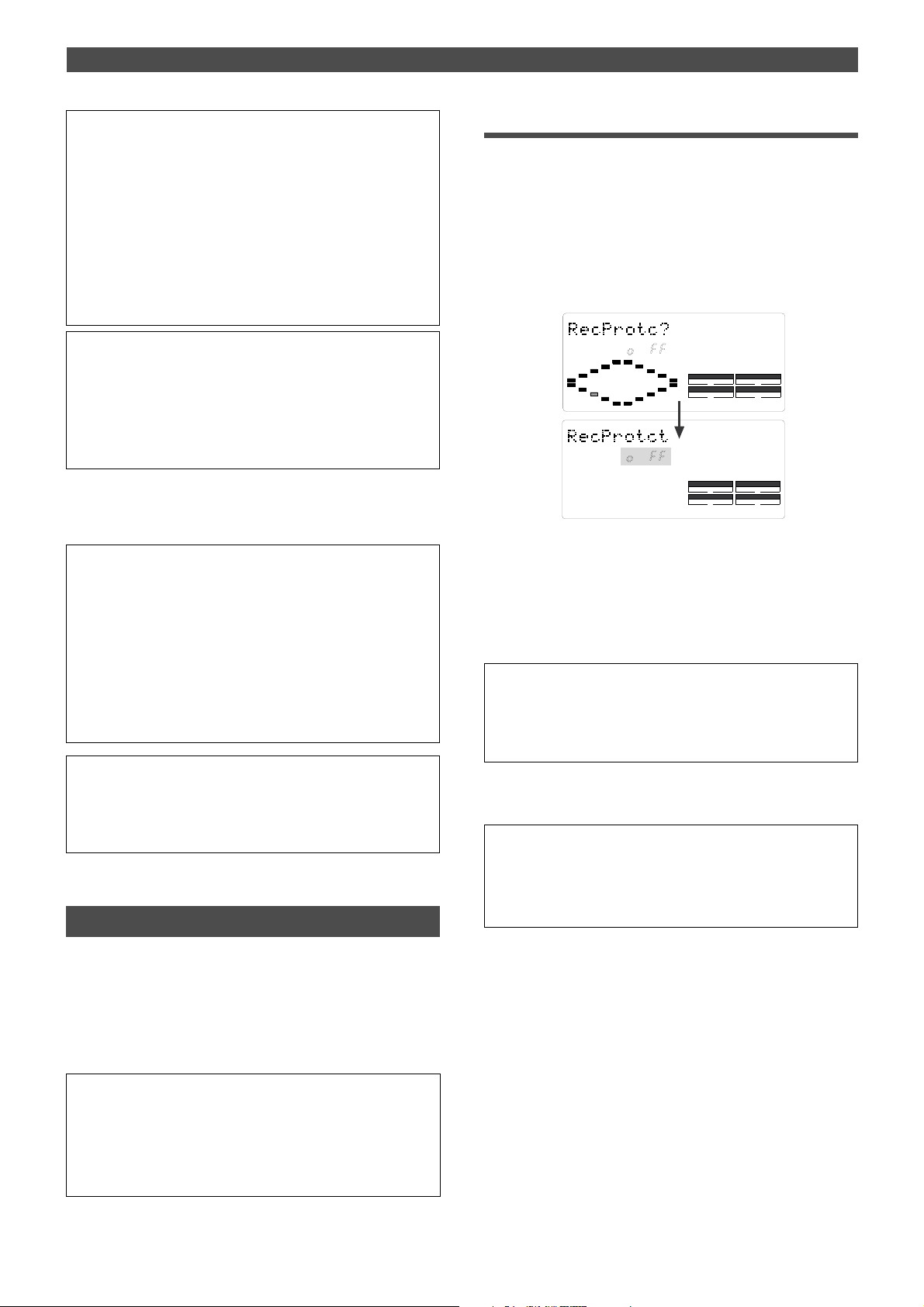
Changing the Initial setting (SETUP mode)
<Note>
• You need to input MTC from an external device to the FD-4 with
any Slave type (external sync signal).
• The FD-4 re-chase window is fixed to ten frames. That is, if an
offset between the master device and slave device exceeds ten
frames, the FD-4 interprets that as out of sync, and tries to chase
and lock to MTC sent from the master device. (This operation is
called “re-chasing.”) During the re-chase operation, audio output
is muted. If the slave machine slips with MTC from the master
device by less than ten frames, the slave machine continues
running while recognizing the slippage.
<Note>
• This menu is used to select a digital signal used for external syn
chronization when Slave mode is turned on. If you wish to specify
the type of digital signals to record, you need to use the “Setting
digital input tracks” menu.
• When you set the Slave type, the Vari Pitch function is
automatically disabled. (The [VARI PITCH] indicator turns off.)
4.Press the EXECUTE/YES key.
The selected Slave type is stored, and “e” and “?” flash
alternately.
<Note>
• If you set the Slave type to [SP diF] (S/P DIF digital signal),
[DIGITAL] lights up on the display when the FD-4 receives a
normal digital signal from the external device. If the signal is
abnormal, the [DIGITAL] and FS (sampling rate) indicators flash
to give you an alarm.
• If you set the Slave type to [SP diF] (S/P DIF digital signal),
approximately two seconds of the sound in the entire system will
be muted when the FD-4 locks or unlocks to clock. Make sure to
input a stable digital signal source.
To cancel the operation, or to restore the setting obtained prior to
the EXECUTE/YES key press, press the STOP button or the EXIT/
NO key. Each time you press one of these keys, the FD-4 returns to
the previous hierarchy level of the menu, and finally exits SETUP
mode and displays the previous Time Base.
Setting the Record Protect function
Recording enabled/disabled
1.While the FD-4 is stopped, press the SETUP key to enter
SETUP mode.
2.Turn the JOG dial to select [Rec Protct (?)] (“t” and “?” flash
alternately), then press the EXECUTE/YES key.
The current setting appears on the display.
Pressing the EXECUTE/YES key turns off the flashing [?]
character, and the recording enabled/disabled indicator
flashes.
With the initial setting, [oFF] flashes as shown below.
SETUP
SETUP
DRIVE
DRIVE
SCSI
SCSI
SYNC OUT
CLK
AUTO A.PUNCH
SYNC OUT
CLK
AUTO A.PUNCH
3.Use the JOG dial to enable or disable recording.
Rotating the JOG dial clockwise and counter-clockwise
will flash [on] and [oFF] alternately.
Selecting [oFF] enables recording; you can record, paste,
and erase data.
Selecting [on] disables recording; and you cannot record,
paste, or erase data.
<Note>
When recording is disabled (on) and you try to record, paste, or
erase data, the FD-4 displays [Protected] for a second, indicating
that you cannot perform the operation. To perform the operation,
you need to enable recording (oFF).
4.Press the EXECUTE/YES key.
“t” and “?” flash alternately.
To cancel the operation, or to restore the setting obtained prior to
the EXECUTE/YES key press, press the STOP button or the EXIT/
NO key . Each time you press one of these keys, the FD-4 returns to
the previous hierarchy level of the menu, and finally exits SETUP
mode and displays the previous Time Base.
The FD-4 features the Record Protect function, which is similar to the function of record-protect tabs on cassette tapes.
The “Setting the Record Protect function” menu allows you
to turn the Record Protect function on and off.
When this function is turned on, you cannot record, paste,
or erase data. Use this function to protect your precious
data from being erased accidentally.
• Initial setting: oFF
• Option: on or oFF
* You can turn the function on and off for each Program individually.
* The settings can be saved and loaded as part of the song data.
* The settings are maintained after you turn off the power to the unit.
* The Program is automatically checked before the operation.
90
Page 91
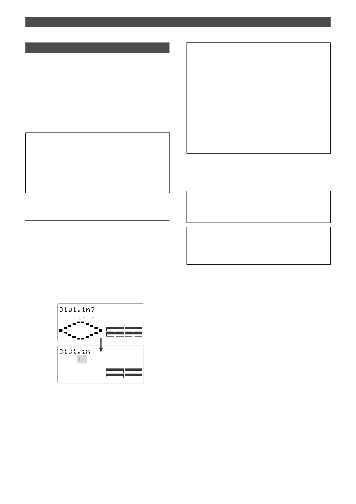
Changing the Initial setting (SETUP mode)
Setting digital input tracks
The “Setting digital input tracks” menu allows you to assign digital signals input at the DATA IN connector of the
FD-4 to the tracks. You can perform digital recording from
an external digital device (CD, MD, DAT, digital mixer, etc.)
using this function.
The number of assignable tracks varies depending on the
recording mode of the connected SCSI disk. If the disk is
formatted in Master 1 mode or Normal mode, you can assign signals to tracks 1–6 (including two Additional tracks).
If the disk is formatted in Master 2 mode, you can assign
signals to tracks 1–4.
• Initial setting: L-, R- (No assign for L and R)
• Assignable tracks: L channel = 1–6, -- (no assign)
R channel = 1–6, -- (no assign)
* If the SCSI disk has been formatted in Master 2, assignable tracks
are 1–4 for L and R.
* This setting is shared by all Programs in the same disk.
* The settings cannot be saved and loaded as part of the song data.
* The settings are maintained after you turn off the power to the unit.
Setting digital input tracks
1.While the FD-4 is stopped, press the SETUP key to enter
SETUP mode.
2.Turn the JOG dial to select [Digi. in ?] (“?” flash alternately),
then press the EXECUTE/YES key.
The current digital input track assignment appears on
the display. Pressing the EXECUTE/YES key turns off the
flashing [?] character, and the L channel setting of the
digital input track flashes.
With the initial setting, L- and r- appear and [L-] flashes
as shown below. You can select a flashing channel to
assign a track.
<Note>
• You cannot assign L channel and R channel to the same track.
If you assign the same track and press the EXECUTE/YES key ,
the last channel you set will have priority, and the first channel will
be automatically set to [-].
For example, if you assign L channel to [2], then assign R
channel to [2], and press the EXECUTE/YES key , L channel will
be set to [L-], and R channel will be set to [r2].
• If the SCSI disk has been formatted in Master 1 or Normal
recording mode, you can assign tracks 5 and 6 (Additional tracks).
If the disk has been formatted in Master 2 mode, and if you try to
assign the channel to track 5 and 6 and record data, record
stand-by mode will be cancelled, and the RECORD TRACK LED
(L,R) will flash quickly . Refer to “Digital Recording” on page 52 for
more information.
4.Press the EXECUTE/YES key.
The selected track assignment is stored, and “?” flashes.
When the FD-4 receives a correct digital signal,
[DIGITAL] lights up on the display.
<Note>
• If [DIGITAL] flashes on the display, check the connection with the
external device, and the settings on the FD-4 and the external
device.
To cancel the operation, or to restore the setting obtained prior to
the EXECUTE/YES key press, press the STOP button or the EXIT/
NO key. Each time you press one of these keys, the FD-4 returns to
the previous hierarchy level of the menu, and finally exits SETUP
mode and displays the previous Time Base.
SETUP
SETUP
DRIVE
DRIVE
SCSI
SCSI
SYNC OUT
CLK
AUTO A.PUNCH
SYNC OUT
CLK
AUTO A.PUNCH
3.Press the HOLD/> key, the REWIND button, or the F FWD
button to select a channel (L or r) and use the JOG dial to
specify a track.
91
Page 92
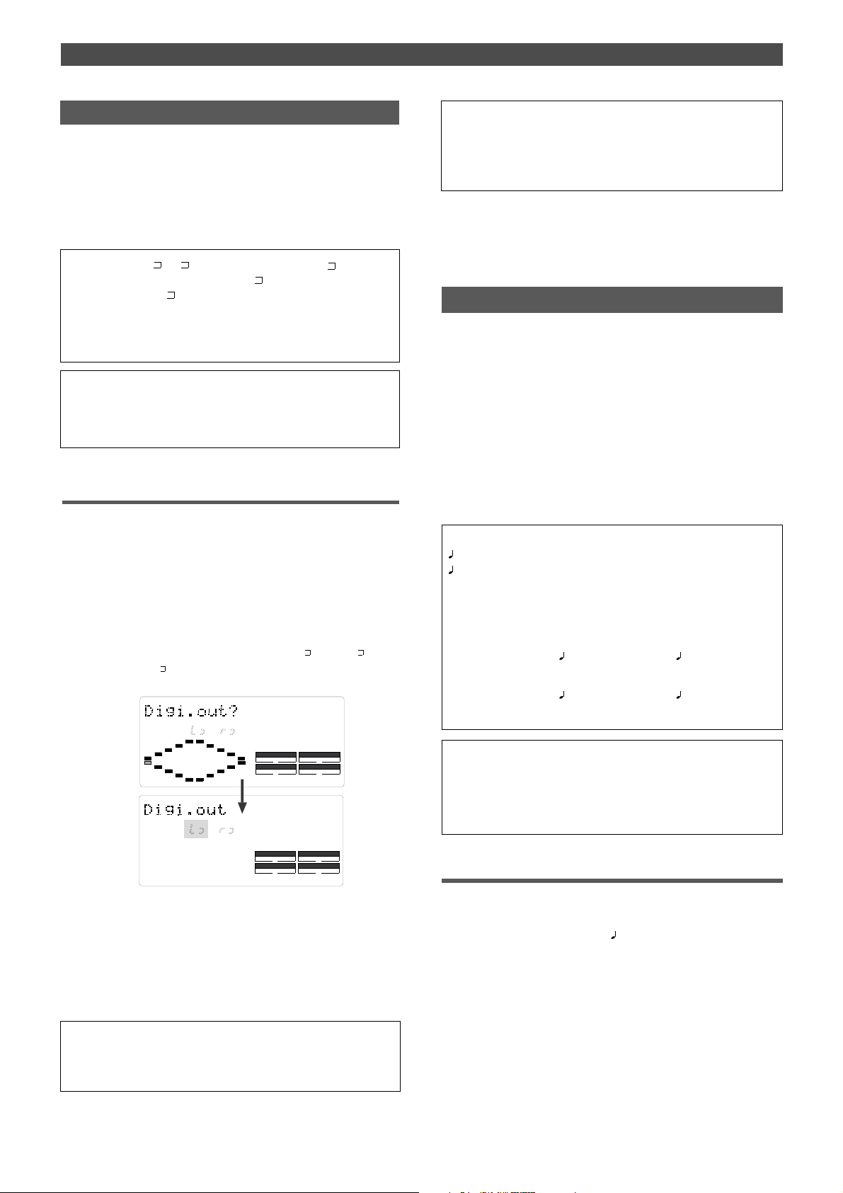
Changing the Initial setting (SETUP mode)
Setting digital output tracks
The “Setting digital output tracks” menu enables you to
assign the track that outputs digital signals from the DATA
OUT connector of the FD-4 to an external digital device.
You can send the recorded audio data on the FD-4 to an
external digital device (MD, DAT, digital mixer, etc.) in the
digital format. Assignable tracks are tracks 1–4 and s-t (STEREO OUT L, R outputs).
• Initial setting: L , r (STEREO OUT L, R output) = s
• Assignable tracks: L channel = 1–4, (STEREO OUT L)
R channel = 1–4, (STEREO OUT R)
* This setting is shared by all Programs in the same disk.
* The settings cannot be saved and loaded as part of the song data.
* The settings are maintained after you turn off the power to the unit.
<IMPORT ANT>
Match the sampling rate of the digital input on the external device
with the sampling rate of the FD-4 to send digital signals from the
FD-4 to the external device.
Setting digital output tracks
1.While the FD-4 is stopped, press the SETUP key to enter
SETUP mode.
2.Turn the JOG dial to select [Digi. out ?] (“?” flashes), then
press the EXECUTE/YES key.
The current digital output track assignment appears on
the display.
Pressing the EXECUTE/YES key turns off the flashing [?]
character, and the L channel setting of the digital output
track flashes. With the initial setting, L
appear, and [L
] flashes as shown below. You can select
a flashing channel to assign a track.
and r
SETUP
To cancel the operation, or to restore the setting obtained prior to
the EXECUTE/YES key press, press the STOP button or the EXIT/
NO key . Each time you press one of these keys, the FD-4 returns to
the previous hierarchy level of the menu, and finally exits SETUP
mode and displays the previous Time Base.
Setting BAR/BEA T resolution mode
The “Setting BAR/BEAT resolution mode” menu enables you
to turn BAR/BEAT resolution mode on and off. The initial
setting is “off.” When you turn this mode on, the CLK (clock)
digits will be always round off to 00 and be stored in the
memory key while the FD-4 is using the BAR/BEAT/CLK
Time Base. That is, beat resolution is used.
Using this function allows you to automatically store a beatresolution value of the CLIPBOARD IN/OUT points and other
points in real-time. (Press the STORE key, then the corresponding memory key while playing the FD-4.)
Therefore, it is very convenient when you perform the Copy
& Paste or Move & Paste operation in beat-resolution.
For example, assume that you have stored the value for 001BAR1
46 CLK as the CLIPBOARD IN point, and the value for 002BAR 4
51 CLK as the CLIPBOARD OUT point.
These values will be used as they are if BAR/BEA T resolution mode
is turned off. However, the mode is turned on, the following values
will be stored instead. The following example has a time signature
setting of 4/4.
001 BAR 1
(A CLK value of 46 will be rounded off.)
002 BAR 4
(A CLK value of 51 will be rounded up.)
46 CLK -> 001 BAR 1 00 CLK
51 CLK -> 003 BAR 1 00 CLK
SYNC OUT
CLK
SYNC OUT
CLK
AUTO A.PUNCH
DRIVE
AUTO A.PUNCH
SETUP
DRIVE
SCSI
SCSI
3.Press the HOLD/> key, the REWIND button, or the F FWD
button to select a channel (L or r) and use the JOG dial to
specify a track.
4.Press the EXECUTE/YES key.
The selected track assignment is stored, and “?” flashes.
When the FD-4 receives a correct digital signal,
[DIGITAL] lights up on the display.
<Note>
If [DIGITAL] flashes on the display, check the connection with the
external device, and the settings on the FD-4 and the external device.
92
• Initial setting: oFF
• Options: on, oFF
* This setting is shared by all Programs in the same disk.
* The settings cannot be saved and loaded as part of the song data.
* The settings are maintained after you turn off the power to the unit.
Setting BAR/BEA T resolution mode
1.While the FD-4 is stopped, press the SETUP key to enter
SETUP mode.
2.Turn the JOG dial to select [
press the EXECUTE/YES key.
The current BAR/BEAT resolution mode setting appears
on the display.
Pressing the EXECUTE/YES key turns off the flashing [?]
character, and the BAR/BEAT resolution mode setting
flashes.
With the initial setting, [oFF] flashes as shown below.
Resolu ?] (“?” flashes), then
Page 93
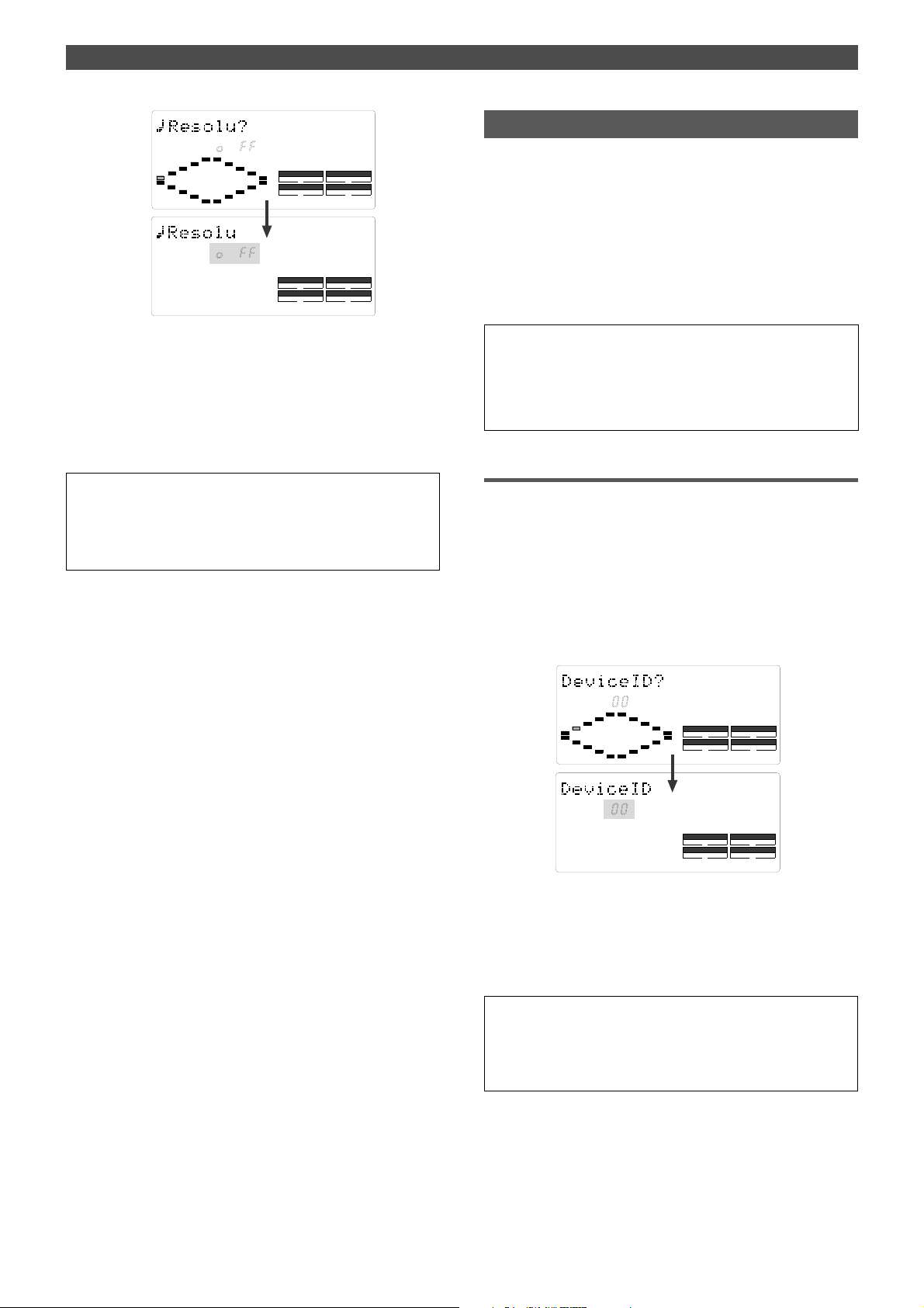
Changing the Initial setting (SETUP mode)
SETUP
SETUP
DRIVE
DRIVE
SCSI
SCSI
SYNC OUT
CLK
AUTO A.PUNCH
SYNC OUT
CLK
AUTO A.PUNCH
3.Use the JOG dial to turn the mode on or off.
When you turn the JOG dial clockwise and counter-clock
wise, [on] and [oFF] flash alternately.
Selecting [on] turns BAR/BEAT resolution mode on, and
selecting [oFF] turns BAR/BEAT resolution mode off.
4.Press the EXECUTE/YES key.
The selected mode setting is stored, and “?” flashes.
To cancel the operation, or to restore the setting obtained prior to
the EXECUTE/YES key press, press the STOP button or the EXIT/
NO key. Each time you press one of these keys, the FD-4 returns to
the previous hierarchy level of the menu, and finally exits SETUP
mode and displays the previous Time Base.
Setting the MIDI device number
The “Setting the MIDI device number” menu enables you
to set the FD-4 device ID number required to control the
unit from a sequence software using MMC (MIDI Machine
Control) or FEX (Fostex System Exclusive Message).
The transmit device ID links to this setting.
You can set the device ID from 00 to 99.
However, if the device ID number of the message the FD-4
receives is [7F], the FD-4 will recognizes it to perform the
corresponding operation, regardless of its device ID setting.
• Initial setting: 00
• Device ID: 00–99
* This setting is shared by all Programs in the same disk.
* The settings cannot be saved and loaded as part of the song data.
* The settings are maintained after you turn off the power to the unit.
Setting the MIDI device ID
1.While the FD-4 is stopped, press the SETUP key to enter
SETUP mode.
2.Turn the JOG dial to select [Device ID?] (“?” flashes), then
press the EXECUTE/YES key.
The current MIDI device ID number appears on the
display.
Pressing the EXECUTE/YES key turns off the flashing [?]
character, and the MIDI device ID number flashes.
With the initial setting, [00] flashes as shown below.
SETUP
SETUP
DRIVE
DRIVE
SCSI
SCSI
SYNC OUT
CLK
AUTO A.PUNCH
SYNC OUT
CLK
AUTO A.PUNCH
3.Use the JOG dial to set the desired MIDI device ID number.
Turning the JOG dial clockwise increments the value, and
turning it counter-clockwise decrements the value.
4.Press the EXECUTE/YES key.
The MIDI device ID number is stored, and “?” flashes.
To cancel the operation, or to restore the setting obtained prior to
the EXECUTE/YES key press, press the STOP button or the EXIT/
NO key. Each time you press one of these keys, the FD-4 returns to
the previous hierarchy level of the menu, and finally exits SETUP
mode and displays the previous Time Base.
93
Page 94

MIDI Implementation Chart/MMC List/Maintenance/Specifications
(Digital Multitracker)
Model FD-4
Function.....................
Basic
Channel
Mode
Note
Number:
Velocity Note ON
After
Touch
Pitch Bend
Control
Change
Default
Changed
Default
Message
Altered
True voice
Note OFF
Key’s
Channel’s
MIDI Implementation Chart
Transmitted
X
X
X
X
*******************************
X
*******************************
X
X
X
X
X
X
X
X
X
X
X
X
X
X
X
X
X
X
X
Recognized
Date:
Version: V1.00
Remarks
Program
Change
:
System Exclusive
: Quarter frame
Common
System
Real Time
Aux.
Message
Notes
: Song Position
: Song Select
: Tune
: Clock
: Commands
: Local ON/OFF
: All Notes OFF
: Active Sense
: Reset
True #
X
*******************************
(rem. 1) (rem. 2)
X
X
(rem. 3)
X
X
X
X
rem. 1: MMC (Device ID=00~99, 127), MTC, Identity reply, FOSTEX Exclusive
rem. 2: MMC (Device ID=00~99, 127), MTC, Inquiry, FOSTEX Exclusive
rem. 3: START, STOP, CONTINUE
X
X
X
X
X
X
X
X
X
X
X
Mode 1: OMNI ON, POLY Mode 2: OMNI ON, MONO
Mode 3: OMNI OFF, POLY Mode 4: OMNI OFF, MONO
94
X:
: Yes
No
Page 95
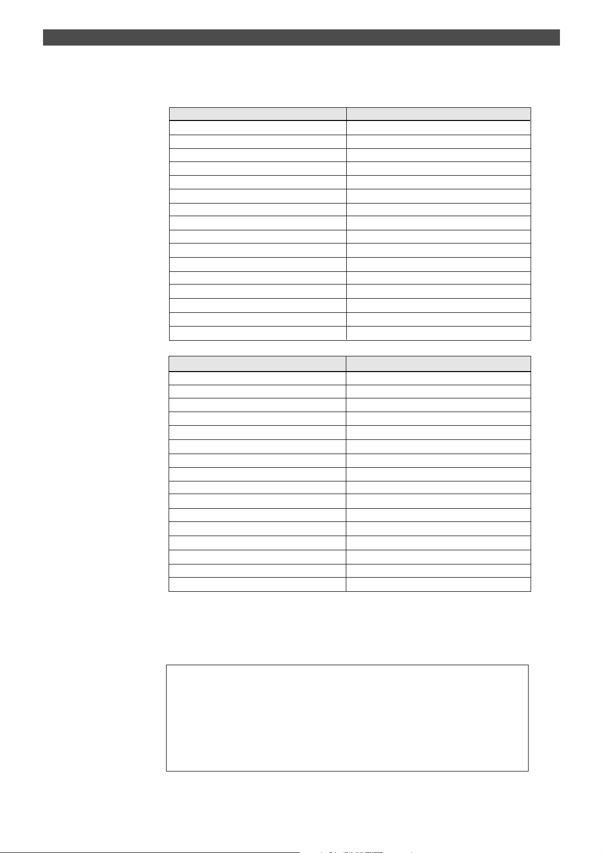
MMC Command List
Command List Movement (Recorder)
01: STOP STOP
02: PLAY PLAY
03: DEFERRED PLAY DEFERRED PLAY
04: FAST FORWARD F FWD
05: REWIND REWIND
06: RECORD STROBE REC
07: RECORD EXIT PUNCH OUT
09: PAUSE STOP
40: WRITE
41: MASKED WRITE
42: READ
44: LOCATE LOCATE to Setting Data
47: SHUTTLE CUE/REVIEW (+/- 1~60 times)
4C: MOVE
4D: ADD
4E: SUBTRACT
MIDI Implementation Chart/MMC List/Maintenance/Specifications
Refer to MMC Response/Information Field List
Refer to MMC Response/Information Field List
Refer to MMC Response/Information Field List
Refer to MMC Response/Information Field List
Refer to MMC Response/Information Field List
Refer to MMC Response/Information Field List
MMC Response/Information Field List Command
01: SELECTED TIME CODE READ/WRITE/MOVE/ADD/SUBTRACT
03: REQUESTED OFFSET READ/WRITE
04: ACTUAL OFFSET READ
08: GP 0 READ/WRITE/MOVE/ADD/SUBTRACT
09: GP 1 READ/WRITE/MOVE/ADD/SUBTRACT
0A: GP 2 READ/WRITE/MOVE/ADD/SUBTRACT
0B: GP 3 READ/WRITE/MOVE/ADD/SUBTRACT
0C: GP 4 READ/WRITE/MOVE/ADD/SUBTRACT
0D: GP 5 READ/WRITE/MOVE/ADD/SUBTRACT
0E: GP 6 READ/WRITE/MOVE/ADD/SUBTRACT
0F: GP 7 READ/WRITE/MOVE/ADD/SUBTRACT
48: MOTION CONTROL TALLY READ
4C: RECORD MODE READ/WRITE
4E: TRACK RECORD STATUS READ
4F: TRACK RECORD READY READ/WRITE/MASKED WRITE
51: RECORD MONITOR READ/WRITE
Inquiry Message List
IDENTITY REQUEST: F0, 7E, <channel>, 06, 01, F7
IDENTITY REPLY: F0, 7E, <channel>, 06, 02, 51, 01, 00, 0F, 00, 01, 00, 7F, 7F, F7
51: Fostex ID
01, 00: Device family code
0F, 00: Device family number FD-4
01, 00, 7F, 7F: Software version
95
Page 96

MIDI Implementation Chart/MMC List/Maintenance/Specifications
Maintenance
Cleaning the exterior
* For normal cleaning, use a soft dry cloth
For stubborn dirt, moisten a cloth in diluted detergent, wring it out firmly, and wipe the dirt off.
Then polish with a dry cloth.
Never use solvents such as alcohol, thinner or benzene, since these will damage the printing and finish of the exterior.
Specifications
* Mixer section
<INPUT 1, 2>
Connector : 6mm Phone jack (x 2)
Input Impedance : 20k ohm or higher
Reference Input Level : -10dBV
<INPUT 3, 4>
Connector : 6mm Phone jack (x 2)
: XLR-3-31 type (x 2)
Input Impedance : 20k ohm or higher
Reference Input Level : L: -50dBV, M: -30dBV,
L: -10dBV
<INSERT 3, 4>
Connector : 6mm Phone jack (x 2)
Load Impedance : 10k ohm or higher
Reference Output Level : -10dBV
Input Impedance : 10k ohm or higher
Reference Input Level : -10dBV
<AUX SEND 1, 2>
Connector : 6mm Phone jack (x 2)
Load Impedance : 10k ohm or higher
Reference Output Level : -10dBV
<AUX RTN 1, 2>
Connector : 6mm Phone jack (x 4)
Input Impedance : 8k ohm or higher
Reference Input Level : -20dBV
<STEREO OUT L, R>
Connector : RCA pin jack (x 2)
Load Impedance : 10k ohm or higher
Reference Output Level : -10dBV
<MONITOR OUT L, R>
Connector : 6mm Phone jack (x 2)
Load Impedance : 10k ohm or higher
Reference Output Level : -10dBV
<PHONES OUT>
Connector : 6mm Stereo Phone jack
Load Impedance : 16 ohm or higher
<RECORDER IN L, R>
Connector : RCA Pin jack (x 2)
Input Impedance : 20k ohm or higher
Reference Input Level : -10dBV
<DATA IN/OUT>
Connector : Optical (x 2)
Format : IEC 958 Part 3 (S/P DIF)
<MIDI IN/OUT>
Connector : DIN 5 pin
Format : MIDI
<PUNCH IN/OUT>
Connector : 6mm Phone jack (x 1)
(An optional FOOT SW Model 8051 can be connected.)
<Equalizer>
HI : 12kHz +/-15dB (Shelving Type)
MID : 200Hz ~ 5kHz +/- 15dB (Parametric Type)
LO : 80Hz +/- 15dB (Shelving Type)
<Frequency Response>
: 20Hz ~ 20kHz
* Recorder section
<Recording/Reproducing>
Recording Medium : External SCSI device
(SCSI-2, asymmetrical transfer)
: Internal 2.5 inch hard disk (EIDE type)
: Connectable SCSI device: One
<Recording Format>
<Recording Mode>
Normal Mode : 4 Real track + 2 Additional
: FDMS-3*
(* Fostex Disk Management
System-3)
track (Sampling Rate: 32kHz/
DAC*)
(*) Digital Audio Acoustic
Coding)
96
Page 97

MIDI Implementation Chart/MMC List/Maintenance/Specifications
Mastering Mode 1 : 4 Real track + 2 Additional
track (Sampling Rate: 44.1kHz/
16-bit linear)
Mastering Mode 2 : 4 Real track (Sampling Rate:
44.1kHz/16-bit linear)
<Digital Input/Output>
* 32kHz/16-bit linear (Normal mode), Corresponds to
DAT 32kHz/SP mode.
* 44.1kHz/16-bit linear (Mastering mode 1, 2)
<Save/Load>
: FDIO-1*
(*) Fostex Data Input /Output-1)
<Recording Track>
<Playback Track>
<Program No.>
<Vari pitch.>
<Crossfade>
: 2 tracks (Analog x 2, or Digital x 2)
: 4 tracks
: Maximum 99 tunes
: +/-6%
: 10msec.
<Recording/reproducing frequency>
: 20Hz ~ 15.5kHz (Normal mode)
: 20Hz ~ 20kHz (Mastering mode 1, 2)
<Total harmonic distortion>
: 0.008% (Mastering mode 1, 2)
<Tempo map>
Signature : 1/4, 2/4, 3/4, 4/4, 5/4, 1/8, 3/8,
5/8, 6/8, 7/8, 8/8
Tempo : quarter note (1/4 note) = 30 ~ 250
* General
<Dimensions (mm)>
<Weight>
<Power supply>
<Power Consumption>
* Specifications and appearance are subject to change
without notice for product improvement.
: 402 (W) x 110 (H) x 355 (D)
: Approx. 4kg
: AC 120V, 60Hz
: AC 230V ~ , 50/60Hz
: 15W
<Dynamic Range>
: 90dB
Block Diagram
INPUT SEL
INPUT
AUX RTN
INPUT SEL
INPUT
OFF
TRK 3
OFF
TRK 1
INSERT3
INPUT 1
-10dBV
INPUT 1
INPUT 2
INPUT 3
-50dBV
BAL
INPUT 3
INPUT 4
L/MONO
-20dBV
R
-10dBV
TRIM
INPUT
FADER
INPUT MON
TRK 1
INPUT
FADER
MON
INPUT
TRK 3
GAIN
GAIN
PAN
L
EQ
GAIN
SHIFT
HI
MID
GAIN
LO
EQ
LO
GAIN
SHIFT
HI
MID
GAIN
AUX 1
AUX 2
MON L
MON R
TRK 1
REC MUTE 1
TRK 2
REC MUTE 2
PAN
AUX 1
AUX 2
MON L
MON R
TRK 3
REC MUTE 3
TRK 4
REC MUTE 4
L
R
R
L
R
ADC
ADC
DATA IN
MASTER
STEREO OUT
L
R
AUX SEND
1
2
MON OUT
L
PHONES
R
1/3/L
RECORDER IN
2/4/R
MON SEL
L/R
L/R +MON
MON
MON
RECORD TRACK
1
2
3
4
L
R
HARD DISK
TRK.1
TRK.2
TRK.3
TRK.4
TRK.L
TRK.R
L
R
DG OUT SETUP
L
R
DAC
DAC
DAC
DAC
DATA OUT
DIGI IN SETUP
L
R
AUX RTN 1
AUX RTN 2
L
R
97
Page 98
Declaration of EC Directive
This equipment is compatible with the EMC Directive (89/336/EEC) - Directive on approximation of member nation's ordinance concerning the electromagnetic compatibility and with the Low Voltage Directive
(73/23/EEC) - Directive on approximation of member nation's ordinance concerning electric equipment
designed to be used within the specified voltage range.
The Affect of Immunity on This Equipment
The affect of the European specification EN50082-1 (coexistence of electromagnetic waves - common immunity specification) on this equipment are as shown below.
* In the electrical fast transient / burst requirements, radiated electromagnetic field requirements and static electricity discharging environment, this could be affected by generation of noise in some cases.
FOSTEX DISTRIBUTORS LIST IN EUROPE
* Including non - EU countries. * underlined: contracted distributors (as of November, 1997)
<AUSTRIA>
NAME: ATEC Audio-u. Videogeraete VertriebsgesmbH.
ADD: Im Winkel 5, A-2325 Velm, Austria
TEL: (+43) 2234-74004, FAX: (+43) 2234-74074
<BELGIUM>
NAME: EML N. V.
ADD: Bijvennestraat 1A, B3500 Hasselt, Belgium
TEL: (+32) 11-232355, FAX: (+32) 11-232172
<DENMARK>
NAME: SC Sound ApS
ADD: Malervej 2, DK-2630 Taastrup, Denmark
TEL: (+45) 4399-8877, FAX: (+45) 4399-8077
<FINLAND>
NAME: Noretron Audio
ADD: Tonttumuorinkuja 4, FIN-02200 Espoo, Finland
TEL: (+358) 0-5259330, FAX: (+358) 0-52593352
<FRANCE>
NAME: Musikengro
ADD: ZAC de Folliouses, B. P. 609, 01706 Les Echets, France
TEL: (+33) 72 26 27 00, FAX: (+33) 72 26 27 01
<GERMANY>
NAME: Studiosound & Music GmbH
ADD: Scheppe Gewissegasse 8, D-35039 Marburg, Germany
TEL: (+49) 6421-12071, FAX: (+49) 6421-15522
<GREECE>
NAME: Bon Studio S. A.
ADD: 6 Zaimi Street, Exarchia, 106.83 Athens, Greece
TEL: (+30) 1-3809605-8, 3302059, FAX: (+30) 1-3845755
<ICELAND>
NAME: I. D. elrf. electronic Ltd.
ADD: Armula 38 108 Reykjavik, Iceland
TEL: (+354) 588 5010, FAX: (+354) 588 5011
<IT ALY>
NAME: Recoton Italia Srl.
ADD:V. 1 Maggio, N 18, 40050 Quarto Inferiore, (BO) Italy
TEL: (+39) 51-768576, FAX: (+39) 51-768336
<THE NETHERLANDS>
NAME: IEMKE ROOS AUDIO B. V.
ADD: Kuiperbergweg 20, 1101 AG Amsterdam, The Netherlands
TEL: (+31) 20-697-2121, FAX: (+31) 20-697-4201
<NORWAY>
NAME: Siv. Ing. Benum A/S
ADD: P. O. Box 145 Vinderen, 0319 Oslo 3, Norway
TEL: (+47) 22-139900, FAX: (+47) 22-148259
<PORTUGAL>
NAME: Caius - Tecnologias Audio e Musica, Lda.
ADD: Rua de Santa Catarina, 131 4000 Porto, Portugal
TEL: (+351) 2-2084456/325400, FAX: (+351) 1-5930716
<SPAIN>
NAME: Multitracker. S. A.
ADD: C/Garcilaso No. 9, Madrid 28010, Spain
TEL: (+34) 1-4470700, 1-4470898, FAX: (+34) 1-5930716
<SWEDEN>
NAME: TTS Tal & Ton Studioteknik AB
ADD: Gelbgjutarevagen 4, S-171 48 Solna, Sweden
TEL: (+46) 8-7340750, FAX: (+46) 8-824476
<SWITZERLAND>
NAME: Audio Bauer Pro AG
ADD: Bernerstrasse-Nord 182, CH-8064 Zurich, Switzerland
TEL: (+41) 1-4323230, FAX: (+41) 1-4326558
<UK>
NAME: SCV London
ADD: 3A 6-24 Southgate Road, London N1 3JJ, England, UK
TEL: (+44) 171-923-1892, FAX: (+44) 171-241-3644
Page 99

INDEX
[A]
ABS time......................................24
Additional track...................26,
30
Analog recording......................28
Auto punch in/out....................43
Auto play....................................66
Auto return.................................67
Auto repeat.................................68
[B]
Backup..............................................76
Bar/beat resolution
setting......92
[C]
Clipboard play....................14, 57
Copy paste..................................56
Cue/review function................62
Can’t Rec display.......................23
[D]
Display............................................20
Disk remain.........................22, 25
Disk error....................................23
Default setting...........................28
Deleting program......................38
Direct locate...............................66
Digital recording.......................52
Digital mixdown........................54
[E]
Erase.................................................58
Entering Setup mode................81
[F]
Formatting the hard disk...........6
Frame rate setting.....................87
[H]
Handling operation..................24
[I]
Input monitor............................26
Inquiry message list..................95
[L]
Load error display.....................23
Locate function..........................66
Locate point................................63
Locate ABS 0...............................66
Locate Rec End...........................66
Loading the data........................79
[M]
Mastering mode 1........................6
Mastering mode 2........................6
MTC.......................................21, 24
Mixdown......................................34
Manual punch in/out...............46
Move and paste.........................56
Metronome function........41, 85
MIDI sync function...................71
MIDI SYNC OUT setting............86
MIDI device setting...................93
MTC frame rate setting............87
MTC OFFSET time......................87
MTC OFFSET MODE..................88
MIDI implementation chart....94
MMC command list...................95
Maintenance...............................96
[N]
Normal mode...............................6
No disk display..........................23
[O]
Over display...............................23
Overdubbing....................................32
[P]
Preset display............................21
Program change........................37
Program delete..........................38
Program title..............................39
Punch in/out..............................43
Ping pong recording.................49
Punch in/out take..............45, 47
Punch in/out rehearsal.....44, 47
Paste..............................................57
Preview function.......................69
Preroll time..........................67, 85
[R]
Recording mode..........................6
Rec+Yes! display........................23
Remain.........................................25
Real track....................................26
Repro monitor...........................26
RECORDER IN jack.....................55
Record protect setting............90
[S]
Shift function.............................14
Shuttle function.........................62
SCSI connector...........................5
Select track display...................23
Stereo bus...................................27
Setting a program.....................36
Storing memory data..............63
Saving data.................................76
Slave mode setting....................88
Slave type setting......................89
Song data...................................76
SETUP mode..............................81
Specifications...............................96
[T]
Time base....................................24
Track exchange.........................60
Time signature setting.............82
Tempo setting............................83
Track over display....................23
[U]
Undo/redo.......30, 33, 46, 48,
58, 60
Unformat display......................22
[V]
Vari pitch function....................40
Void out display........................22
Void data display......................22
[W]
Warning message......................22
Page 100

FOSTEX CORPORA TION
3-2-35, Musashino, Akishima-shi, Tokyo, Japan 196-0021
FOSTEX CORPORA TION OF AMERICA
15431, Blackburn Ave., Norwalk, CA 90650, U. S. A.
C PRINTED IN JAPAN APR. 1998 8288 414 100 FX
 Loading...