

Page 1
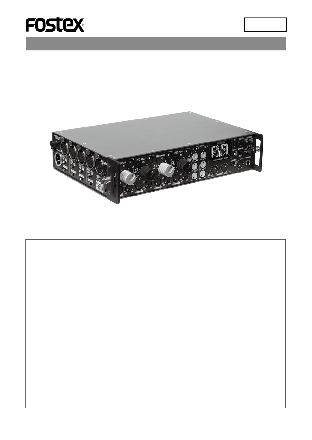
Owner’s Manual
FM-4
PORTABLE MIXER
8289670000
(505068)
Thank you very much for purchasing the Fostex FM-4 portable mixer.
To ensure the best performance, read this manual thoroughly before using the unit. Keep this
manual handy for future reference.
Table of contents
Safety Instructions . . . . . . . . . . . . . . . . . . . . . . .2
Precautions . . . . . . . . . . . . . . . . . . . . . . . . . . . . . 4
Precautions before using . . . . . . . . . . . . . . . . . . 4
Precautions on installation . . . . . . . . . . . . . . . . .
Main features . . . . . . . . . . . . . . . . . . . . . . . . . . .5
Basic operations . . . . . . . . . . . . . . . . . . . . . . . .6
Preparation of power supply . . . . . . . . . . . . . . . 6
Prepararion of input channels . . . . . . . . . . . . . .
Preparation of output channels . . . . . . . . . . . . .
Preparation of metering . . . . . . . . . . . . . . . . . . .
Preparation of monitoring . . . . . . . . . . . . . . . . . .
Master fader reference setting . . . . . . . . . . . . . .
Master fader reference setting . . . . . . . . . . . . . .
Audio setting . . . . . . . . . . . . . . . . . . . . . . . . . . . .
Block diagram . . . . . . . . . . . . . . . . . . . . . . . . .10
Names and functions . . . . . . . . . . . . . . . . . . .11
Front panel . . . . . . . . . . . . . . . . . . . . . . . . . . . . . 11
Left side panel . . . . . . . . . . . . . . . . . . . . . . . . . .
Right side panel . . . . . . . . . . . . . . . . . . . . . . . . .
14
15
4
7
7
7
8
8
9
9
Display . . . . . . . . . . . . . . . . . . . . . . . . . . . . 17
Adjusting the display brightness . . . . . . . . . . . 17
Selecting the meter mode . . . . . . . . . . . . . . . .
Selecting the status display . . . . . . . . . . . . . . .
Input status display . . . . . . . . . . . . . . . . . . . . . .
T12 power supply mode setting . . . . . . . .
Output status display . . . . . . . . . . . . . . . . . . . .
Status information details . . . . . . . . . . . . .
Limiter parameter setting . . . . . . . . . . . . . .
Meter status display . . . . . . . . . . . . . . . . . . . . .
Parameter setting procedure . . . . . . . . . . .
Parameter details . . . . . . . . . . . . . . . . . . . .
Peak meter on/off . . . . . . . . . . . . . . . .
VU meter reference level . . . . . . . . . . .
Lighting level of peak over indicator . .
Internal battery selection . . . . . . . . . . .
System status display . . . . . . . . . . . . . . . . . . . .
Initializing the flash memory
Specifications . . . . . . . . . . . . . . . . . . . . . . . . . .25
External dimensions . . . . . . . . . . . . . . . . . . . .27
. . . . . . . . . . . . 24
18
18
19
19
20
21
21
22
22
23
23
23
23
23
24
Page 2
CAUTION
RISK OF ELECTRIC SHOCK
DO NOT OPEN
CAUTION: TO REDUCE THE RISK OF ELECTRIC SHOCK,
DO NOT REMOVE COVER (OR BACK).
NO USER - SERVICEABLE PARTS INSIDE.
REFER SERVICING TO QUALIFIED SERVICE PERSONNEL.
"WARNING"
"TO REDUCE THE RISK OF FIRE OR ELECTRIC SHOCK, DO NOT
EXPOSE THIS APPLIANCE TO RAIN OR MOISTURE."
SAFETY INSTRUCTIONS
1. Read Instructions - All the safety and operating instructions should be read before the appliance is operated.
2. Retain Instructions - The safety and operating instruc
tions should be retained for future reference.
3. Heed Warnings - All warnings on the appliance and in
the operating instructions should be adhered to.
4. Follow Instructions - All operating and use instructions
should be followed.
5. Water and Moisture - The appliance should not be used
near water - for example, near a bathtub, washbowl,
kitchen sink, laundry tub, in a wet basement, or near a
swimming pool, and the like.
6. Carts and Stands - The appliance should be used only
with a cart or stand that is recommended by the manu
facturer.
An appliance and cart combination should be moved
with care. Quick stops, excessive force, and uneven sur
faces may cause the appliance and cart combination to
overturn.
7. Wall or Ceiling Mounti ng - The appli ance s hould be
mounted to a wall or ceiling only as recommended by
the manufacturer.
8. Ventilation - The appliance should be situated so that
its location or position dose not interfere with its proper
ventilation.
For example, the appliance should not be situated on a
bed,sofa, rug, or similar surface that may block the ven
tilation openings; or, placed in a built-in installation, such
as a bookcase or cabinet that may impede the flow of air
through the ventilation openings.
9. Heat - The appliance should be situated away from heat
sources such as radiators, h eat registers, stoves, or
other appliances (including amplifiers) that produce heat.
10. Power Sources - The appliance should be connected to
a power supply only of the type described in the operat
ing instructions or as marked on the appliance.
11. Grounding or Polarization - The precautions that should
be taken so that the grounding or polarization means of
an appliance is not defeated.
12. Power Cord Protection - Power supply cords should
be routed so that they are not likely to be walked on or
pinched by items placed upon or against them, paying
particular attention to cords at plugs, convenience re
ceptacles, and the point where they exit from the appli
ance.
CAUTION:
TO PREVENT ELECTRIC SHOCK, MATCH WIDE BLADE OF
PLUG TO WIDE SLOT, FULLY INSERT.
ATTENTION:
POUR EVITER LES CHOCS ELECTRIQUES, INTRODUIRE
LA LAME LA PLUS LARGE DE LA FICHE DANS LA BORNE
CORRESPONDANTE DE LA PRISE ET POUSSER JUSQU'
AU FOND.
The lightning flash with arrowhead symbol, within an
equilateral triangle, is intended to alert the user to the presence
of uninsulated "dangerous voltage" within the product's
enclosure that may be of sufficient magnitude to constitute a
risk of electric shock to persons.
The exclamation point within an equilateral triangle is intended
to alert the user to the presence of important operating
and maintenance (servicing) instructions in the literature
accompanying the appliance.
-
13. Cleaning - The appliance should be cleaned only as recommended by the manufacturer.
14. N onu se Periods - The power cord of the appliance
should be unplugged from the outlet when left unused
for a long period of time.
15. Object and Liquid Entry - Care should be taken so that
objects do not fall and liquids are not spilled into the en
closure through openings.
16. Damage Requiring Service - The appliance should be
-
-
-
-
-
-
serviced by qualified service personnel when:
A. The power supply cord or the plug has been dam
aged; or
B. Objects have fallen, or liquid has been spilled into
the appliance; or
C. The appliance has been exposed to rain; or
D.
E. The appliance has been dropped, or the enclosure
17. Servicing - The user should not attempt to service the
18. The appliance should be situated away from drops of
19. Objects containing liquid such as vase must not be put
20. The appliance is not completely isolated from the power
21. Apparatus shall not be exposed to dripping or splashing
22. O nly use attach men ts/accessorie s specified by the
23. An appliance with a protective earth terminal should be
24. An appliance should be placed in a position where an
25. Main plug is used as the disconnection device. It shall
The appliance does not appear to operate normally
or exhibits a marked change in performance; or
damaged.
appliance beyond that described in the operating in
structions. All other servicing should be referred to quali
fied service personnel.
water or spray of water.
on the appliance.
supply even if the power switch is at off position.
and no objects filled with liquids, such as vases, shall be
placed on the apparatus.
manufacturer.
connected to a mains outlet with a protective earth con
nection.
AC plug / inlet can be easily pulled out by hand.
remain readily operable and should not be obstructed
during intended use. To be completely disconnected
the apparatus from supply mains, the mains plug of the
apparatus shall be disconnected from the mains socket
outlet completely.
-
-
-
-
-
2
Page 3

Important Safety Instructions
1) Read these instructions.
2) Keep these instructions.
3) Heed all warnings.
4) Follow all instructions.
5) Do not use this apparatus near water.
6) Clean only with dry cloth.
7) Do not block any ventilation openings.
Install in accordance with the manufacturer's
instructions.
8) Do not install near any heat sources such as
radiators, heat registers, stoves, or other
apparatus (including amplifiers) that produce
heat.
9) Do not defeat the safety purpose of the
polarized or grounding-type plug. A polarized
plug has two blades with one wider than the
other. A grounding type plug has two blades
and a third grounding prong. The wide blade
or the third prong are provided for your safety.
If the provided plug does not fit into your
outlet, consult an electrician for replacement
of the obsolete outlet.
11) Only use attachments/accessories specified
by the manufacturer.
12) Use only with the cart, stand, tripod, bracket,
or table specified by the manufacturer, or
sold with the apparatus. When a cart is
used, use caution when moving the cart /
apparatus combination to avoid injury from
tip-over.
13) Unplug this apparatus during lightning
storms or when unused for long periods
of time.
14) Refer all servicing to qualified service
personnel. Servicing is required when the
apparatus has been damaged in any way,
such as power-supply cord or plug is
damaged, liquid has been spilled or objects
have fallen into the apparatus, the apparatus
has been exposed to rain or moisture, does
not operate normally, or has been dropped.
15) Excessive sound pressure from earphones
and headphones can cause hearing loss.
10) Protect the power cord from being walked
on or pinched particularly at plugs,
convenience receptacles, and the point
where they exit from the apparatus.
3
Page 4
Precautions
FM-4
FM-4
Precautions before using
• Do not supply the voltage that does not match the
voltage requirement of the unit.
• If you operate the unit on battery power, use alkaline
or nickel hydride batteries.
• If you supply the power to the unit from the AC power
outlet, only use the optional dedicated Fostex AC
adaptor.
If you use any other AC adaptor, the unit may not work
correctly and there is a serious risk of damage to the
unit.
• If you wish to use the unit in a country where the volt
age of the AC power outlet does not match your AC
adaptor, ask your local Fostex dealer or service station
for purchasing an appropriate AC adaptor. Note that
the AC adaptor can be used both in 50 Hz and 60 Hz
areas.
• Do not let water or other liquid, or metal objects such
as pins, accidentally enter the inside of the unit.
Should water enter the inside of the unit, turn off
the power, unplug the AC adaptor and remove
batteries,and consult your dealer or the nearest
FOSTEX service station.
• Do not drop the unit or give it a strong shock.The in
ternal circuits, display or panels may be damaged.
Precautions on installation
Do not install the unit in the following conditions.
* In an extremely hot or cold place
* In a moist place
* In a strong magnetic field or near a device which
generates a magnetic field
* In the direct rain or water
<Note>: The unit is designed for outdoor use, however, it is not waterproof. Do not use the unit in the direct
-
-
water.
Notes on moisture condensation
When you bring the unit from a cold place to a warm
place, moisture may condense on the display, pan
els, etc. In such a case, turn off the power and leave
the unit for a while until it warms up and evaporates
any moisture.
-
• To prevent possible electric shock and damage to the
unit, do not remove the cover or reach the inside of
the unit.
<Important!>
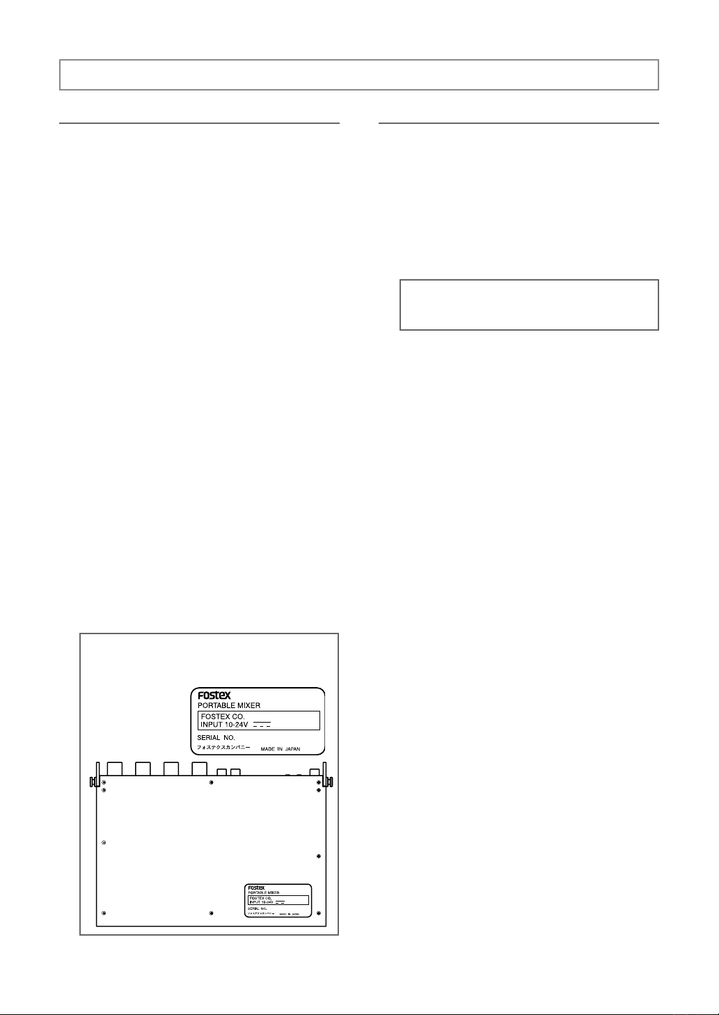
Equipment name, electrical ratings, serial number and other information for the FM-4, are writ
ten on bottom side.
-
4
Page 5

Main features
Mixer section features
• Four input channels and two output channels.
These are transformer-balanced.
• The analog VCA limiter is provided on each of left and
right stereo output channels. You can select the de
sired threshold level and compression ratio using the
output status display.
• In addition to the [MAIN OUT] (L/1, R/2) outputs, [SUB
OUT] (L/3, R/4), [TAPE OUT] and [AUX OUT] (1, 2)
outputs are also provided, allowing comprehensive
connection to external audio equipment.
• You can monitor signals from the [AUX IN] input, as
well as you can mix them with the main input signals.
By connecting the [AUX OUT] output to the [AUX IN]
input of another FM-4 (or FM-3), you can cascade two
FM mixers.
• You can connect a microphone or line-level source to
each of the [INPUT] 1 through 4 inputs.
The unit can provide P48 or T12 power to a condenser
microphone connected to each input.
• Each input signal can be positioned anywhere in the
stereo field using the pan pot provided on each input
channel.
• Two 2-band EQ channels are provided. You can
equalize up to two input signals.
• Both 1/4-inch phone and stereo mini jacks are provid
ed for headphone monitoring. You can use two stereo
headphones simultaneously.
• AR (anti-reflection) coating is applied to the protection
plate for the display to reduce reflection.
• Each input channels provides the trim control and twocolor peak indicator for optimum level adjustment.
• Frequently used controls such as the input trim con
-
trols, channel faders, monitor-related switches, etc.,
are placed on the front panel for central
• Pop up knobs are used for the input trim, panpot,
HPF, EQ, [PHONES] and [MASTER] controls to avoid
inadvertent operation.
• You can view the positions of all switches on the side
panel from the input status and output status displays.
control.
-
Power supply features
• The unit can be operated on battery or AC power.
You can fit the battery box with eight AA alkaline or
nickel hydride batteries inside the unit or connect the
optional AC adaptor (or external battery).
*Note that no battery is supplied with the unit.
• Up to five-hour continuous operation is possible us
ing alkaline batteries. (Note that the actual continuous
operation time depends on the circumstance.)
• The battery box is supplied with the unit, however, it is
also available in option. For long continuous use, it is
recommended to purchase the optional battery box
as a spare.
-
• The [DC-OUT] connector is provided for supplying DC
power to an external wireless receiver, etc.
-
• The monitor select switch allows you to select the
signal for headphone monitoring. In addition, the [PFL
(Pre Fader Listen)] switch allows you to directly moni
tor each of [INPUT] 1 through 4 signals.
• The output level of the [MAIN OUT] (L/1, R/2) and [SUB
OUT] (L/3, R/4) connectors can be independently se
lected from +4 dBu, 0 dBu, -10 dBu and -60 dBu.
Display and control features
• The 128 x 64 dot-matrix display using organic LED
devices shows the VU (needle) and peak (bar-graph)
meters simultaneously.
• You can select the meter display mode from stereo,
mono left and mono right.
• The battery indicator on the display always shows
battery remaining, while the [EMPTY] indicator and
-
alert display warn you when the battery voltage is
low.
Other features
-
• For lightweight and rigidity, aluminum is used for panels, etc.
• Compact size design, a great advantage for outside
use.
• The shoulder belt and soft protection case are avail
able in option. Ask your local Fostex dealer or service
station for details about optional products.
-
5
Page 6
Basic operations
Preparation of power supply
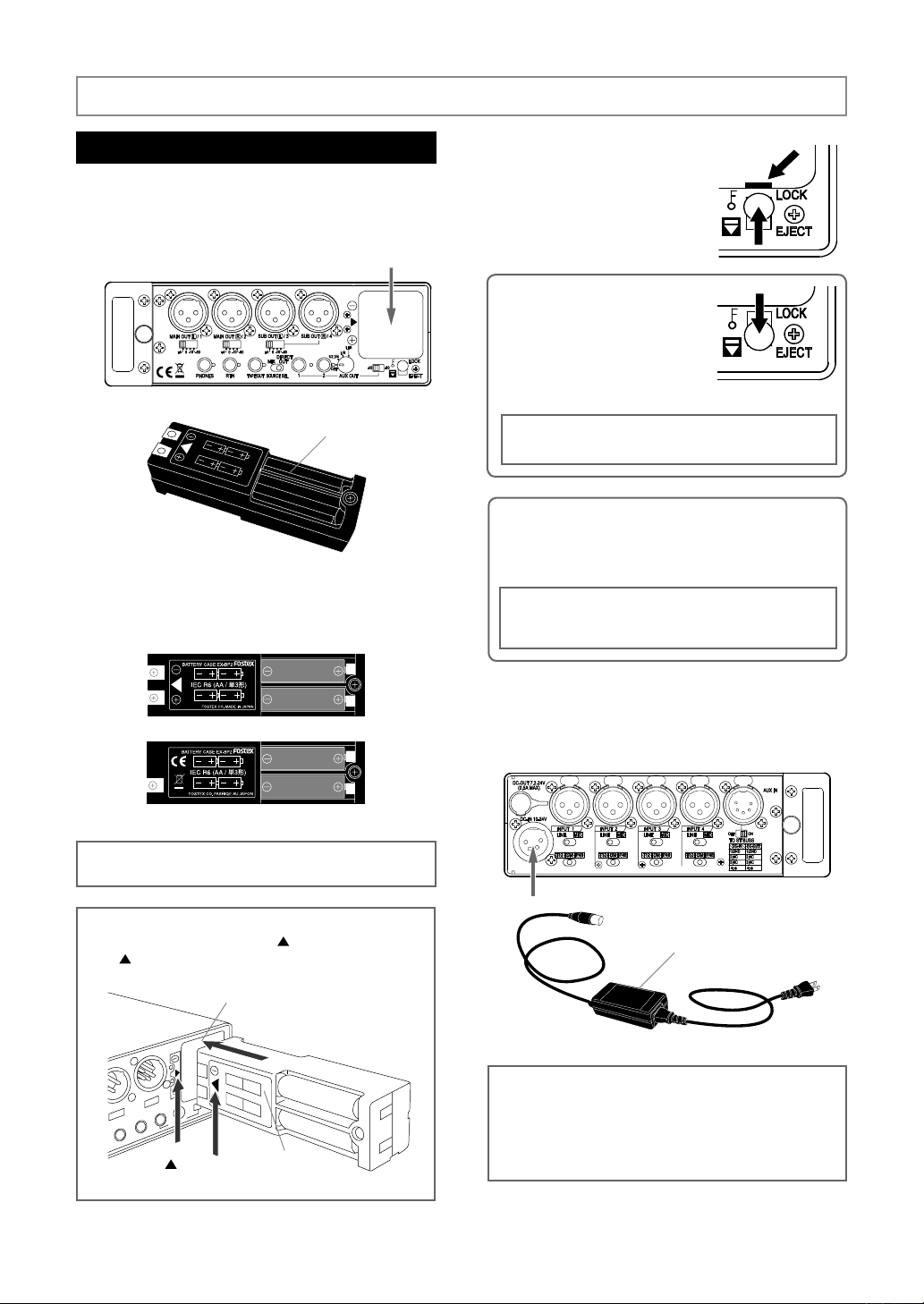
To operate the unit on internal battery power, set AA
alkaline or nickel hydride batteries to the supplied
battery box and fit the box to the battery compart
ment on the right side panel.
Battery box compartment
Battery box
Make sure to set alkaline or nickel hydride batteries
to the battery box in correct direction as marked on
the box. Set four batteries on each side of the bat
tery box.
After fully inserting the battery
Tab
box, slide up the [EJECT/LOCK]
lever to the LOCK position.
A tab appears as shown on the
-
-
right figure and the battery box
is locked.
<Memo>: To remove the battery
box, slide down the [EJECT/LOCK]
lever to unlock the battery box.
The battery box is slid to the front a
few millimeters and you can pull it
out by hand.
<Note>: Before you remove the battery box, turn off the
power or set the [POWER] switch to the “EXT position.
<Memo>: You can set the battery type (alkaline or nickel
hydride) to be used from the meter display. By default, it is
set for alkaline batteries. If you use nickel hydride batteries,
change the battery type setting (see page 23).
<Note>: If the battery type setting do not match the batteries currently used, the EMPTY indicator, battery indica
tor and alert display do not work correctly.
-
<Note>: Always use eight new alkaline or fully charged nickel
hydride batteries of the same model and same capacity.
<Note>: Insert the battery box to the battery box compartment in
the correct direction by matching the
to the
symbol on the panel of the unit.
Battery box compartment
Symbol
symbol on the battery box
Battery box
To operate the unit on external power, connect the
optional dedicated AC adaptor or an external battery
to the [DC-IN] connector on the left side panel.
Optional AC adaptor or
external battery
<Note>: The rated voltage of the [DC IN] connector is DC 10
V to 24 V. When you connect an external power source to
the [DC IN] connector, use the appropriate power source that
matches the rated voltage of the [DC IN] connector.
For the detail information on the pin assignment of the [DC IN]
connector, see page 14 of “Features and controls”.
6
Page 7
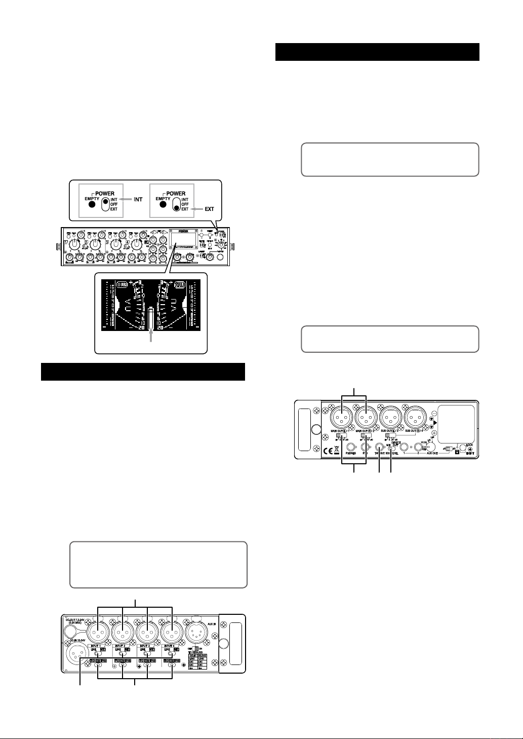
1
32
You can turn on the unit by setting the [POWER]
Batteryindicator
13
2
4
switch on the front panel to “INT” (upper position) or
“EXT” (lower position). When you operate the unit on
internal battery power, set the switch to “INT”.
When you operate the unit on external power, set it
to “EXT”. When you turn on the unit for the first time,
the display shows the stereo VU meters as shown
below. Wh en y ou operate th e unit on (inte rnal
on external) battery power, confirm that the battery
power is sufficient by checking the battery indicator
on the meter display.
You can check the power voltage of the battery pow
er source from the system status display (see page
23).
Preparation of output channels
• To send the stereo output signals to an external
audio device
You can send the stereo mixed signals to an external audio
device from the [MAIN OUT] (L/1, R/2) connectors.
(1) Set the [SOURCE SEL] switch to “MIX”.
-
(2) Connect an external audio device such as a
<Memo>: The [SUB OUT] (L/3, R/4) connectors
also send the same signals as the [MAIN OUT] (L/1,
R/2) connectors.
recorder to the [MAIN OUT] (L/1, R/2) connectors.
Preparation of input channels
(1) Connect a microphone or line level source to
each of the [INPUT] connectors (1 through 4).
(2) When you connect a microphone, set the
input select switch to “MIC”. When you con
nect a line level source, set the input select
switch to “LINE”.
(3) When you connect a microphone, set the mi
crophone power supply switch appropriately.
When you connect a condenser microphone that
requires +48 V phantom power, set the switch to
“P 48” . Whe n you con nec t a con den ser micro
phone that requires T-12 power (A-B 12 V) such as
Sennheiser 416T, set the switch to “P48”. When
you connect a dynamic microphone, set the switch
to “DM”.
<M em o>: I f you d o no t nee d T12 (A- B 12 V)
power supply capability, you can disable this ca
pability from the input status display. By default, it
is enabled. See page 19 for details.
-
(3) Set the output level switch appropriately de
pending on the device connected.
You can set the nominal output level to +4
dBu, 0 dBu, -10 dBu or -60 dBu.
(4) To connect a -10 dBV unbalanced line level
device, use the [TAPE OUT] jack (stereo mini
jack). The nominal output level of this jack is
fixed to -10 dBV.
<Memo>: The stereo buss signal is output from
the [TAPE OUT] jack.
-
-
-
• To output each input signal directly
You can send “post-fader” input signals of the INPUT 1
through 4 from the [MAIN OUT] (L/1, R/2) and [SUB OUT]
(L/3, R/4) connectors respectively.
(1) Set the [SOURCE SEL] switch to “DIRECT
OUT”.
(2) Connect the external device(s) to the [MAIN
OUT] and/or [SUB OUT] connectors.
-
(3) Set the output level switch appropriately to
match the external device.
You can set the nominal output level to +4
dBu, 0 dBu, -10 dBu or -60 dBu.
7
Page 8
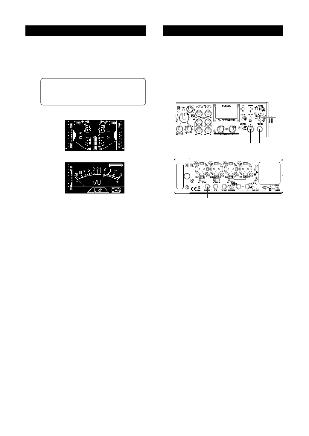
1
12
2
Preparation of monitoringPreparation of metering
(1) Select stereo or mono metering.
When the unit is shipped, the display is set to ste-
reo VU and peak metering.
You can change it to L or R channel mono metering
(see page 18 for details).
<Memo>: Using the meter status display, you can
disable or enable the peak meter function, select the
VU meter reference level, and select the “OVR” indi
cator lighting level (see page 22 for details).
Stereo metering
Mono metering (L)
-
(2) Adjust the display brightness if required.
When the unit is shipped, the display brightness is
set to “Level 3”.
You can change it to the optimum brightness ac
cording to the circumstance. See page 17 for de
tails.
(1) C onne c t h eadp h o n es to t h e 1/4 - i n ch
[PHONES] jack on the front panel or the miniphone [PHONES] jack on the right side panel.
You can use both the 1/4-inch a nd min i-phone
jacks simultaneously.
(2) Set the monitor select switch to “ST” and
adjust the monitor level using the [PHONE]
control.
-
-
8
Page 9
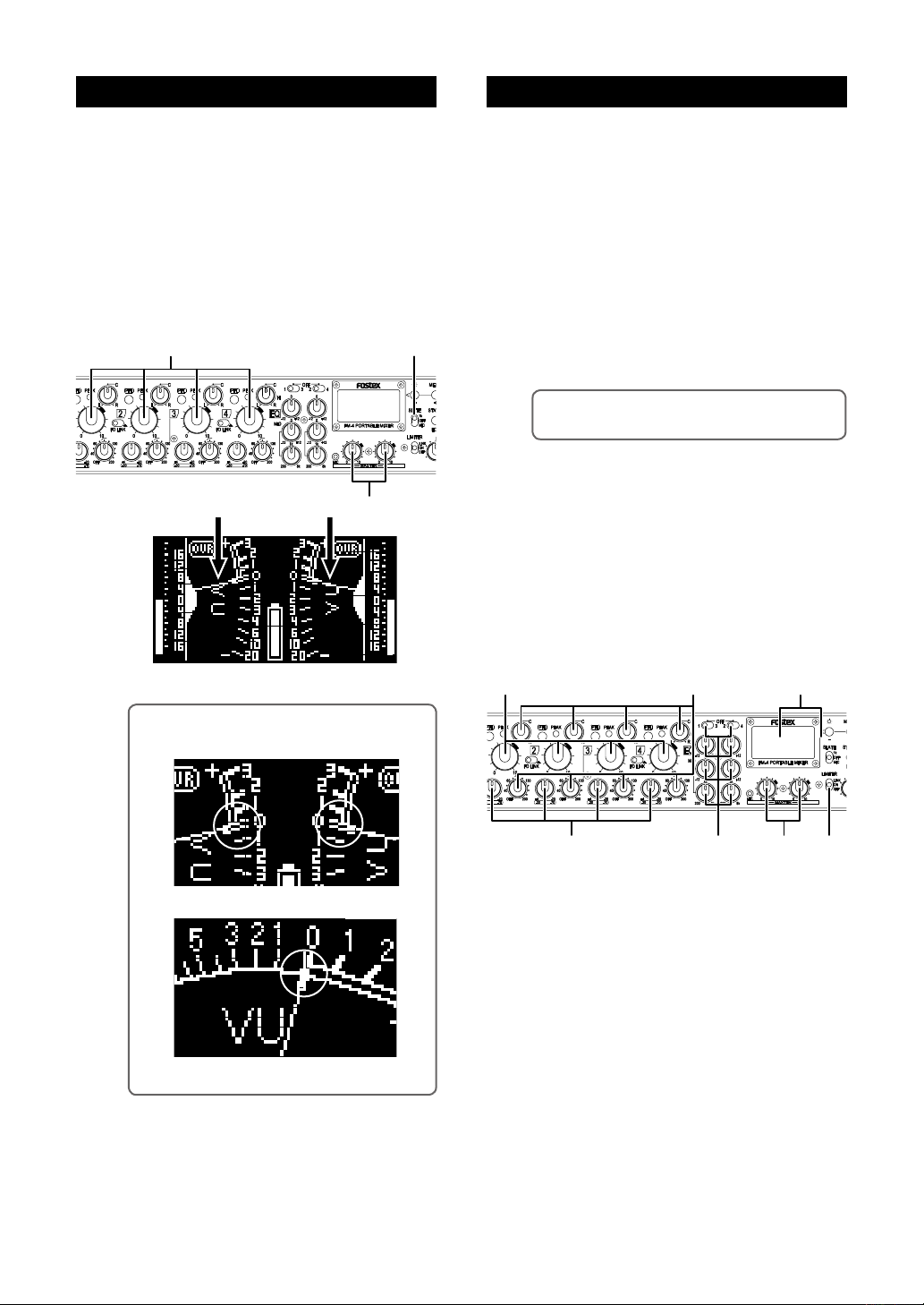
1,4
3
2
6
1
3
2
2 4
5
Audio settingMaster fader reference setting
(1) Turn down the rotary faders on input chan-
nels 1 through 4.
(2) Set the [SLATE] switch on the front panel to
“1k” (upper position).
(3) Se t th e [MASTER] L and R faders t o th e
two-o’clock position (marked in orange) so
that the meter needles point to 0 VU (see the
figure below).
Normally this is the reference output position.
(1) Set the [MASTER] faders to the reference po-
sition.
(2) Receive input si gna ls an d adjust the trim
control of each channel.
Adjust the trim control appropriately so that the
peak indicator does not light in red at the maximum
sound level.
(3) Raise up the channel fader of each channel
gradually until the meter shows the proper
level.
(4) Set the pan and HPF controls of each input
channel appropriately if required.
<Memo>: The HPF cuts the unnecessary low fre-
quency range, such as wind blowing.
(5) If you want to apply the EQ to input channels,
set the EQ switches and controls appropriately.
To use the EQ, select the input channels you apply
the EQ to using the EQ switches and make EQ set
ting using the EQ controls. If you do not apply the
EQ to an input channel, set the EQ switch to OFF.
(6) If you want to apply the limiter to the main
output, set the [LIMITER] switch to “ON” (or
“LINK”).
-
<Memo>: In the following figures, the meter needles point the reference (0 VU).
(4) After adjusting the reference level, switch the
[SLATE] switch to “OFF”.
Stereo metering
Mono metering
9
Page 10
P
P
P
BAL
BAL
P
BAL
BAL
P
P
P
MINI-JACK
BA
BA
BAL
BAL
MIX
MIX
MIX
MINI-JACK
BA
BA
HA
HA
HA
HPF
HPF
HPF
BA
BA
BA
MINI-JACK
BA
BA
HA
MINI-JACK
STD-JACK(6.3)
HA
MIX
HA
HPF
P
BA
P
P
LCR
LCR
LCR
LCR
MIX
MIC
AGC
BA
RMS
VCA
BA
RMS
BA
BA
VCA
P.EQ
P.EQ
1
2
3
1
2
3
1
2
3
1
2
3
PBAP
MINI-JACK
BA
RTN_L
RTN_L
RTN_R
RTN_R
POST[1]
POST[2]
POST[3]
POST[4]
MIX_BUS_R MIX_BUS_R
MIX_BUS_L MIX_BUS_L
PFL_ON
PFL_ON
POST[1]
POST[2]
POST[3]
POST[4]
TONE
MIC
PFL
PFL_BUSPFL_BUS
HA_OUT[4]
HA_OUT[3]
HA_OUT[2]
HA_OUT[1]
POST[1]
POST[2]
POST[3]
POST[4]
POST[1-4]
L+R
MON_L
MON_L
MON_L
MON_L
MON_L
MON_L
MON_R
MON_R
MON_R
MON_R
MON_R
MON_R
MON_R
AUX_IN_R
AUX_IN_R
AUX_IN_L
AUX_IN_L
AUX1_L
AUX1_R
AUX2_L
AUX2_R
AUX2_R
AUX2_L
AUX1_R
AUX1_L
AUX1_L
AUX1_R
AUX2_L
AUX2_R
D_OUT_L
D_OUT_R
D_OUT_R
D_OUT_L
T12P48
MIC POWER
LINE
MIC
LINE MIC
MIC POWER
MIC
MIC
P48
LINE
T12
LINE
MIC POWER
MIC
MIC
P48
LINE
T12
LINE
+4/0/-10/-60dBu
+4/0/-10/-60dBu
+4/0/-10/-60dBu
TAPE OUT
MAIN OUT L
MAIN OUT R
SUB OUT L
AUX MIX SW
AUX IN
CH1 IN
CH2 IN
CH3 IN
AUX OUT1
-10/-60dBV
LINE:(+ 4 ~ -20dBu)
MIC :(-30 ~ -70dBu)
LINE:(+ 4 ~ -20dBu)
MIC :(-30 ~ -70dBu)
LINE:(+ 4 ~ -20dBu)
MIC :(-30 ~ -70dBu)
PAN
PEAK
DET.
+4dBu
RTN
R
HP.VOL.
L+R
L+R
AUXRRTN
L
L/R
PHONE1
L
L/R
AUX
PHONE2
RTN
L-R
MS
MS
L-R
L-R
MON_SEL
AUX_SEL
P48
LINE:(+ 4 ~ -20dBu)
MIC :(-30 ~ -70dBu)
LINE
MIC POWER
CH4 IN
T12
MICLINE
MIC
MIX DIRECT
SOURCE SEL
PAN
PAN
PFL2
PFL3
PFL4
PFL1
LINK
OFF ON
LINK
OFF ON
PAN
MIC
OSC:1kHz
OFF
1kHz
ON
OFF
LIMITER
LINK
LINK
OFF
ON
OFF
ON
MPU
OLED METER
VU&PEAK
INTEGRAL
CH2
EQ
EQ
CH1
OFF
ON
ON
EQ
OFF
OFF
CH4
EQ SEL
EQ SEL
OFF
EQ
OFFONCH3
ON
OFF
PEAK
DET.
PEAK
DET.
PEAK
DET.
SUB OUT R
AUX OUT2
-10/-60dBV
1/2
OFF
L+R
L/R
1/2
OFF
L+R
L/R
OFF
L+R
L+R
L/R
3/4
L/R
3/4
OFF
O.P.
Port
-10/-60dBV
GAINGAINFRQ
GAINFRQ GAIN
DIGITAL OUT
OPTION
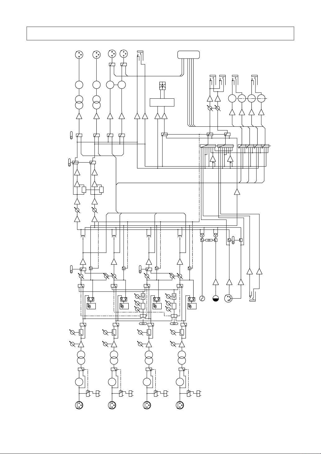
Block diagram
10
Page 11
1 2 3 6 7 8 9101154
212019 18 13 1215
14
17 16
Names and functions
Front panel
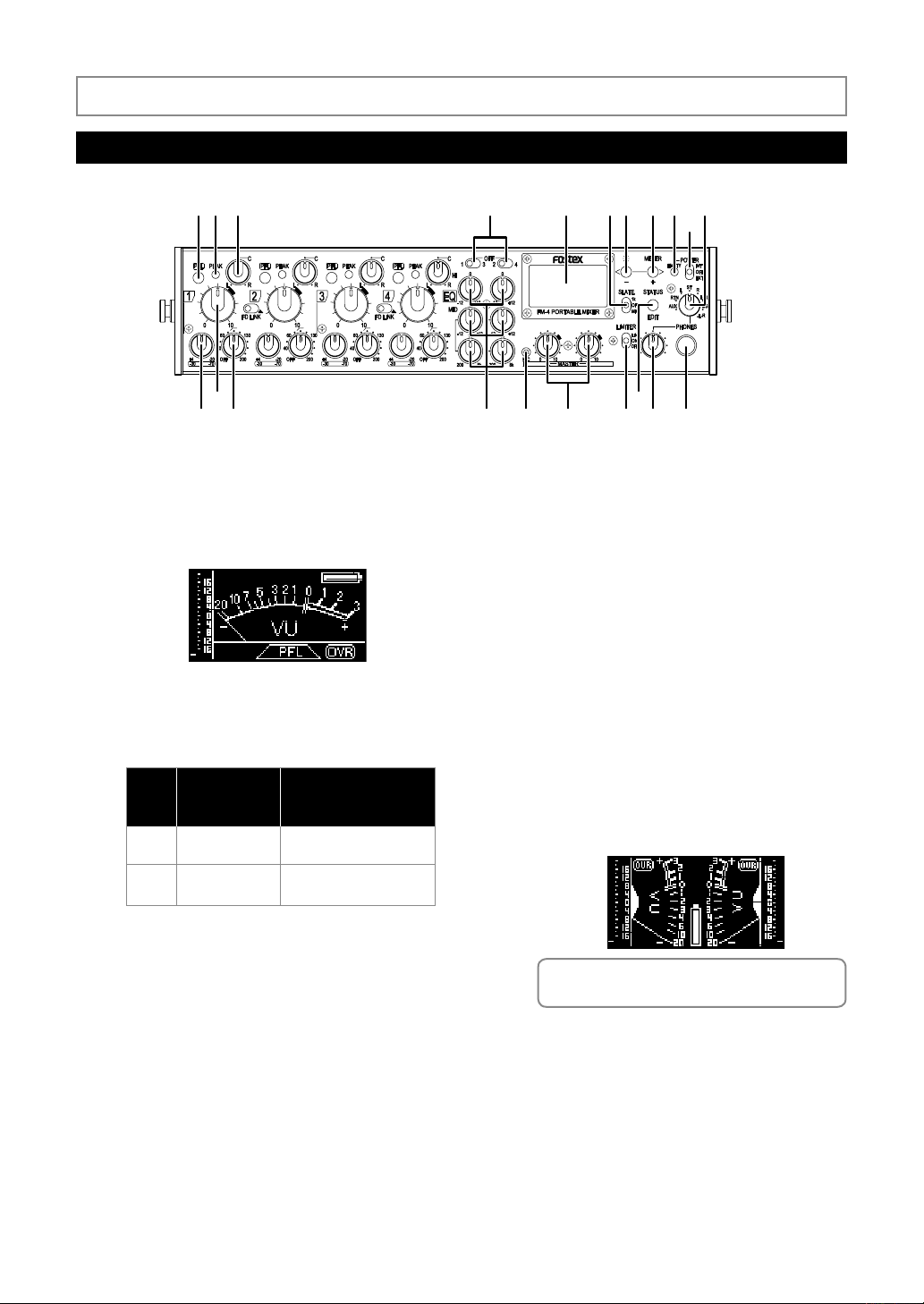
1. [PFL] (Pre Fader Listen) keys (1 through 4)
While pressing down the key, the pre-fader signal
(before the inpu t channel f ade r) is outp ut fro m
the [PHONES] jacks. In this condition, the display
shows the PFL signal
level metering as below.
2. PEAK indicators (1 through 4)
Each indicator lights according to the signal level of
the corresponding input channel as follows.
Color
(compared with the
Green
Red
Lighting level
reference level)
+8dB
+17dB
Approximately -12dB below
the internal maximum level
Approximately -3dB below
the internal maximum level
Details
3. Pan controls (1 through 4)
Each pan control determines the position of the
corresponding input signal in the stereo image.
A pop-up type knob is used for each pan control.
It pops up when you push it once. Pushing it again
makes it locked on the same level as the panel.
4. EQ switches (1-3, 2-4)
The unit features a couple of EQ channels. Each EQ
switch selects the input channel to which the cor
responding EQ is to be applied.
• 1-3 switch: By setting it to the left position, you can
apply EQ to input channel 1. By setting it to the
right position, you can apply EQ to input channel 3.
By setting it to the center position, this EQ channel
is disabled.
• 2-4 switch: By setting it to the left position, you can
apply EQ to input channel 2. By setting it to the
right position, you can apply EQ to input channel 4.
By setting it to the center position, this EQ channel
is disabled.
5. Display
The 128 x 64 dot-matrix display using organic LED
devices shows the VU (needle) and peak (bar-graph)
meters, battery status, etc. When you first turn on
the unit after purchasing, the stereo VU and peak
meters are shown.
<Memo>: For details about the contents of the
display, see “Display details” on page 17.
-
11
Page 12

6. [SLATE] switch (1k / OFF / MIC)
When it is set to “1k”, a 1-kHz slate tone is gener-
ated and sent to the stereo L and R busses. While
you hold it down to “MIC”, the internal slate micro
phone signal is sent to the stereo L and R busses.
12. [PHONES] jack
You can con nect st er eo he ad ph ones wi th the
1/4-inch plug for monitoring.
Connector: 1/4” stereo phone jack
7. [ ] / [-] key
Holding down this key for a second or more enters
the brightness adjustment mode.
In the brightness adjustment mode, meter selection
mode or status display mode, this key acts as the [-]
key (see page 17).
8. [METER] / [+] key
Holding down this key for a second or more enters
the meter selection mode. In the brightness adjust
ment mode, meter selection mode or status display
mode, this key acts as the [+] key (see page 18).
9. EMPTY indicator
This indicator flashes when the battery voltage falls
below the threshold while you operate the unit on
battery power (see page 23).
In normal condition, this indicator is unlit.
10. [POWER] switch (INT / OFF / EXT)
This switch turns the unit on or off.
When you operate the unit on external power (using
the optional AC adaptor or external battery), set it
to EXT.
When you operate the unit on internal battery pow
er, set it to INT.
11. Monitor select switch
This switch selects the signals monitored from the
[PHONE] jacks on the front and right side panels.
You can monitor signals received from the [AUX
AUX
IN] in stereo.
You can monitor signals received from the [RTN]
RTN
in stereo.
You can monitor the left channel signal of the
L
stereo buss in mono.
You can monitor the stereo buss signal in stereo.
ST
You can monitor the right channel signal of the
R
stereo buss in mono.
You can monitor the L+R signal (i.e. the L com
L+R
ponent of MS matrix) in mono.
You can monitor the MS decoded signals (i.e.
MS
L+R from the left, L-R from the right).
You can monitor the L-R signal (i.e. the R com-
L-R
ponent of MS matrix) in mono.
-
13. Headphones level control
This control is used to adjust the output level of
both the 1/4-inch and mini [PHONES] jacks.
14. [STATUS] / [EDIT] key
Holding down this key for a second or more enters
the s tatus mod e. In this mode , you can swit ch
among status display pages as well as you can edit
parameters (see page 18).
-
In the status display mode, this key acts as the
[EDIT] key (see page 18). Pressing this key briefly
exits the current mode while pressing the key for a
second or more enters or exits the parameter edit
-
ing mode.
In the brightness adjustment mode or meter selec
-
tion mode, this key acts as the enter key.
15. [LIMITER] switch (ON, OFF, LINK)
This switch enables or disables the limiter function.
The limiter can work individually or in link, as de
-
scribed below.
The limiter circuit is inserted after the [MASTER]
fader.
The limiter function is enabled with the left and
-
right channels linked. If either of left and right
LINK
channel signals exceeds the threshold, both the
left and right channel limiters work in the same
way.
The limiter function is enabled. Each of the left
ON
and right limiters works independently.
The limiter function is disabled (the limiter circuit
OFF
is bypassed).
The limiter parameters are factory-preset as shown
below.
You can change the threshold level and ratio from
the output status display (see page 21).
<Factory preset values>
• Attack time:
Approximately 5 milliseconds (fixed)
• Release time:
Approximately 200 milliseconds (fixed)
• Threshold: +12 dB (can be changed to +9 dB
or +6 dB)
• Ratio: 5:1 (can be changed to 3:1)
12
Page 13
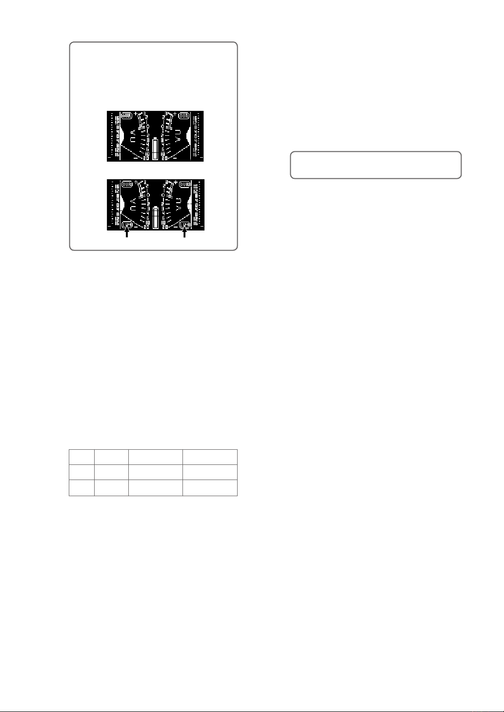
<M em o>: When yo u se le ct the [LIM IT ER ]
switch to ON or LINK, the meter display shows
“LIM” (p ointed by arro ws below). When the
limiter is working, “LIM” flashes. The following
shows display examples of the stereo meter
display.
When the switch is set to OFF
When the switch is set to ON or LINK
“LIM” icon
“LIM” icon
16. [MASTER] faders (L and R)
These faders con trol s tereo lef t and ri ght buss
output levels. The scale position in orange shows
the reference position. A pop-up type knob is used
for each fader. It pops up when you push it once.
Pushing it again makes it locked on the same level
as the panel.
17. [MIC] (Slate microphone)
A slate microphone is built in. While holding down
the [SLATE] switch to the “MIC” position , the
slate microphone is active and the signal from the
microphone is sent to the stereo buss.
19. HPF controls (1 through 4)
Each control sets the high pass filter function.
At the left-most position (OFF position), the HPF
ci rcu it is bypass ed. R otati ng th e con tro l kno b
clockwise switches on the HPF (with a click). De
pending on the position, you can set the HPF cutoff frequency between 40 Hz and 200 Hz (at -12
dB/oct.).
A pop-up type knob is used for each HPF control.
It pops up when you push it once. Pushing it again
makes it locked on the same level as the panel.
<Memo>: The HPF cuts the unnecessary low fre-
quency range, such as wind blowing.
20. Channel faders (1 through 4)
Each fader controls the signal level sent to the ste-
reo buss.
The scale position in orange shows the reference
position.
21. Input trim controls (1 through 4)
Ea ch contro l adjusts the in put gain o f the cor-
responding input channel. When the input select
switch is set to MIC, you can adjust the gain be
tween -70 dBu and -30 dBu.
When the input select switch is set to LINE, you
can adjust the gain between -20 dBu and +4 dBu.
It is recommended to adjust the control so that the
PEAK indicator does not light in red at the maxi
mum input level.
A pop-up type knob is use d for each control. It
pops up when you push it once. Pushing it again
makes it locked on the same level as the panel.
-
-
-
18. EQ controls
These cotrols adjust EQ setting.
The FM-4 provides two EQ channels featuring the
HI and sweepable MID bands.
Band Type
HI
Shelving
Sweepable
MID
The three controls on the left side adjust the EQ for
the input channel selected by the EQ 1-3 switch,
while the three controls on the right side adjust the
EQ for the input channel selected by the EQ 2-4
switch.
From the top row, these are the HI gain, MID gain
and MID frequency controls.
A pop-up type knob is used for each EQ control. It
pops up when you push it once. Pushing it again
makes it locked on the same level as the panel.
Frequency
10 kHz
200 Hz to 8 kHz
Gain range
-12 dB to +12 dB
-12 dB to +12 dB
13
Page 14
1 2
5 4 36
7
Left side panel
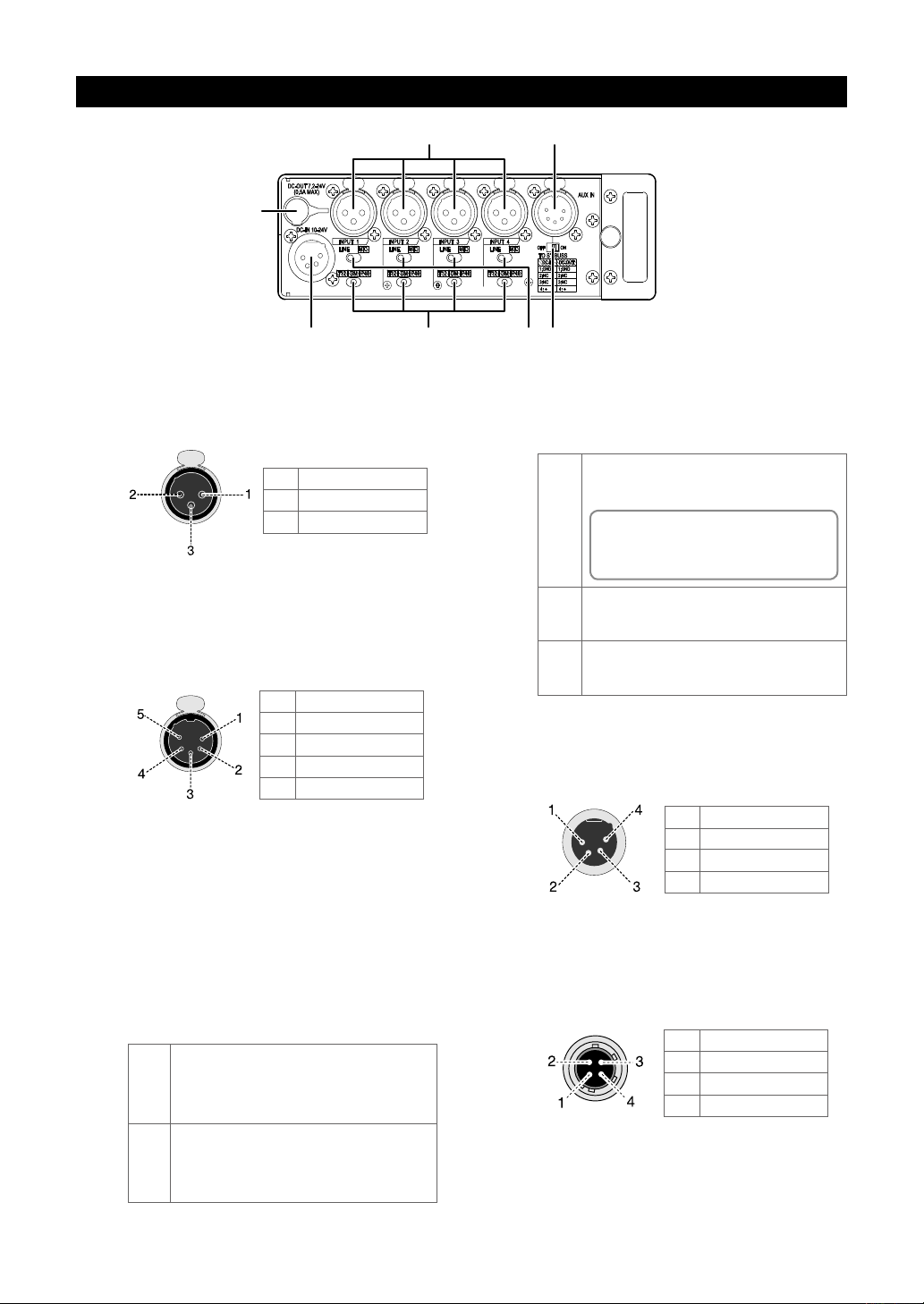
1. [INPUT] connector (1 through 4)
Each connector is used to connect an external au-
dio
device or microphone.
Connector: XLR-3-31 type
1
2
3
GND
HOT
COLD
2. [AUX IN] connector
Used to connect a mixer or audio device.
Not only you can monitor the input signal of this
connector, you can send the signal to the stereo
buss to mix with the main input signals (selectable
with the [TO ST BUSS] switch).
Connector: XLR-5-51 type
1
2
3
4
5 Rch COLD
GND
Lch HOT
Lch COLD
Rch HOT
3. [TO ST BUSS] switch (ON / OFF)
This switch selects whether or not the input signal
from the [AUX IN] jack is sent to the stereo buss.
To send the [AUX IN] signal to the stereo buss, set
the switch to ON. When the switch is set to OFF,
5. Microphone power supply switches
(T12 / DM /P48)
Each switch sets whether or not supplying the
mi-
crophone power.
T12 or AB power supply mode. A 12 V power is
supplied to the hot terminal of the [INPUT] connector.
T12
<Me mo> : I f y ou do not need T12 powe r
suppl y, you can disabl e th e power supply
via the input status display (see page 19 for
details).
No microphone power is supplied. When you
DM
connect a dynamic microphone, set the switch
to DM.
48-volt phantom power supply mode.
P48
A 48 V po wer is s upplied to the hot and cold
terminals of the [INPUT] connector.
6. [DC IN 10-24V] connector
Used to connect the supplied AC adaptor (or an
external battery).
Connector: XLR-4-32 type (male)
1
2
3
4
GND
NC
NC
DC 10 V to 24 V
the [AUX IN] signal is not sent to the stereo buss.
Regardless of the switch setting, you can monitor
the
[AUX IN] signal via headphones.
4. Input select switches (LINE / MIC)
Each switch should be set appropriately according
to
the input signal source of the corresponding [IN-
7. [DC OUT 7.2-24V] connector
This connector outputs power at DC 7.2 to 24 V / 0.5 A
for a wireless receiver, etc.
It outputs power when the unit is powered on.
Connector: Hirose 4-pin HR10A-7R-4S
PUT] connector.
You should set the switch to LINE when a linelevel source is connected to the [INPUT] connector. When it is set to LINE, the microphone power
LINE
supply is automatically turned off regardless of
its setting.
You should set the switch to MIC when a microphone is connected to the [INPUT] connect or.
MIC
You can sup ply the microphone powe r w hen
connecting a condenser microphone (see “ Microphone power supply switch” below).
Applicable plug: HR10A-7R-4P
1
2
3
4
GND
NC
NC
DC 7.2 V to 24 V
14
Page 15
10111213 6
2
1 4
5
789
3
Right side panel
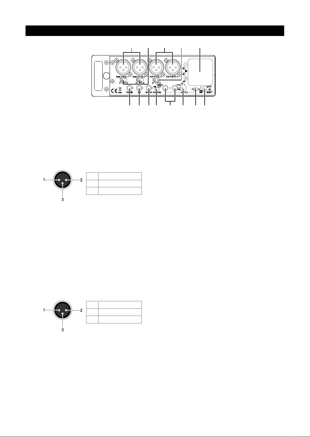
1. [MAIN OUT (L/1, R/2)] connectors
These connectors output the stereo buss (L, R) sig-
nals or input channel 1 and 2 signals. You can se
lect the output signals by using the SOURCE SEL
switch. You can select the reference output level
using the MIAIN OUT level select switches.
Connector: XLR-3-32 type
1
2
3
GND
HOT
COLD
2. MAIN OUT level select switches
Each switch selects the output level of the [MAIN
OUT] L/1 or R/2 conn ect or. You ca n select th e
reference level of these connectors independently
from +4 dBu, 0 dBu, -10 dBu and -60 dBu.
3. [SUB OUT (L/3, R/4)] connectors
These connectors output the stereo buss (L, R) sig
nals or input channel 3 and 4 signals. You can select
the output signals by using the SOURCE SEL switch.
You can select the reference output level using the
SUB OUT level select switch.
Connector: XLR-3-32 type
5. Battery compartment
You can set the battery box that houses eight AA
-
alkaline or nickel hydride batteries (see page 6).
When you u se int er na l ba tt ery pow er, set the
[POWER]
switch to “INT”.
6. [EJECT/LOCK] lever
This lever locks or unlocks the battery box.
When you remove the battery box, slide down this
lever to unlock the battery box (see page 6).
7. AUX OUT level select switch
This switch selects the output reference level of the
[AUX OUT (1, 2)] jacks between -10 dBV and -60
dBV.
8. AUX OUT select switch
This switch selects the output signal sources of the
[AUX OUT (1 and 2)] jacks.
-
• OFF: No signal is output from AUX 1 and 2.
• L/R: Stereo (L and R) buss signals are output from
AUX 1 and 2.
• L+R: Stereo (L and R) buss signals are mixed and
output from AUX 1 and 2 in mono.
• 1/2 3/4: The post-fader signals of input channels 1
and 2 are output from AUX 1, while the post-fader
signals of input channels 3 and 4 are output from
AUX 2.
1
2
3
GND
HOT
COLD
4. SUB OUT level select switches
This switch selects the output level of the [SUB
OUT] (L/1 and R/2) connectors. You can select the
reference level of these connectors from +4 dBu, 0
dBu, -10 dBu and -60 dBu.
9. [AUX OUT (1, 2)] jacks
These jacks output the signals selected by the AUX
OUT select switch described above.
Connector: 3.5 mm stereo mini-phone jack
15
Page 16

10 [SOURCE SEL] switch
Selects the source signal of the [MAIN OUT] and
[SUB OUT] connectors. You can select the mas
ter stereo signal or the post-fader signals of input
channels 1 through 4.
-
Switch
position
MIX
DIRECT Inputs (1, 2) Inputs (3, 4)
MAIN OUT
(L/1, R/2)
St er eo buss
(L, R)
SUB OUT
(L/3, R/4)
St er eo buss
(L, R)
Notes
The stereo buss
signal is output.
The post-fa der
sig na ls o f th e
input chan nel s
are output.
<Note>: When you select the DIRECT position,
you cannot apply the limiter to the output signals
of the [MAIN OUT] connectors.
11. [TAPE OUT] jack
This jack outputs the unbalanced stereo buss sig-
nal. The reference level is fixed to -10 dBV.
Connector: 3.5 mm stereo mini-phone jack
12. [RTN] jack
This jack accepts a -10 dBV stereo signal.
Connector: 3.5 mm stereo mini-phone jack
13. [PHONES] jack
You can connect stereo headphones with the 3.5 mm
plug for monitoring.
You can monitor the same signal as the [PHONES]
jack in the front panel simultaneously.
Connector: 3.5 mm stereo mini-phone jack
16
Page 17
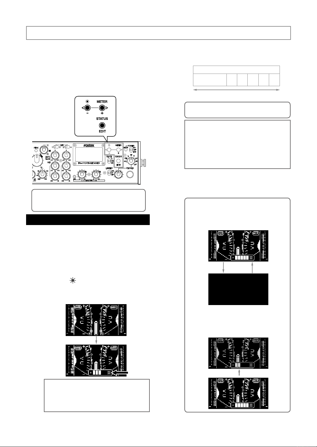
Display
The display on the front panel of the unit normally
shows the VU and peak meters. You can select
stereo or mono metering. The display also can
show the status of inputs, outputs, etc., which you
can edit. You can also adjust the display bright
ness to match the circumstance.
For display-related operation, the following three
keys are used.
<Memo>: In the following description, “press the key
long enough” means “hold down the key for more than
one second”.
Adjusting the display brightness
You can set the display brightness to match the
circumstance (by default, it is set to level 3).
(2) Press the [-] key to lower the brightness or
press the [+] key to increase the brightness.
You can select from OFF and 1 through 5.
-
(3) By pressing the [EDIT] key immediately after
Turning off the
display
[-] key (darker)
<M em o> : If yo u press t he [+] key w he n the
brightness is set to OFF, the display gets brighter.
<Note>: If you set the brightness level to any
level between 1 through 5, the setting is stored to
the flash memory. However, if you set it to OFF,
the setting is not stored to the flash memory, and
when you turn on the unit the next time, the dis
play is shown at the brightness level that was set
before entering the brightness setting mode last
time.
adjusting the brightness level, the brightness
adjustment bar disappears and the unit exits
the display brightness adjustment mode.
<Memo>: When the brightness adjustment bar
is shown, pressing the [-] key long enough sets
the brightness to OFF, while pressing the [+] key
returns the brightness to the previous level be
fore entering the brightness adjustment mode.
Brightness
2 3 4 5
1
[+] key (brighter)
-
-
The display brightness setting remains even af
ter you turn off the unit. If you initialize the flash
memory using the system status display, it is reset
to the default setting (see page 24).
(1) Press the [ ] key long enough to enter the
display brightness adjustment mode.
The brightness adjustment bar appears, showing
the current brightness level.
<Memo>: If you do not press any key for approximately five seconds while the brightness
adjustment bar is shown, the bar automatically
disappears and the unit exits the display bright
ness adjustment mode.
-
-
Turning off the display
When the brightness is set to any level lower
than the maximum level, pressing the [+] key
long enough directly sets the brightness to the
maximum level.
17
Page 18
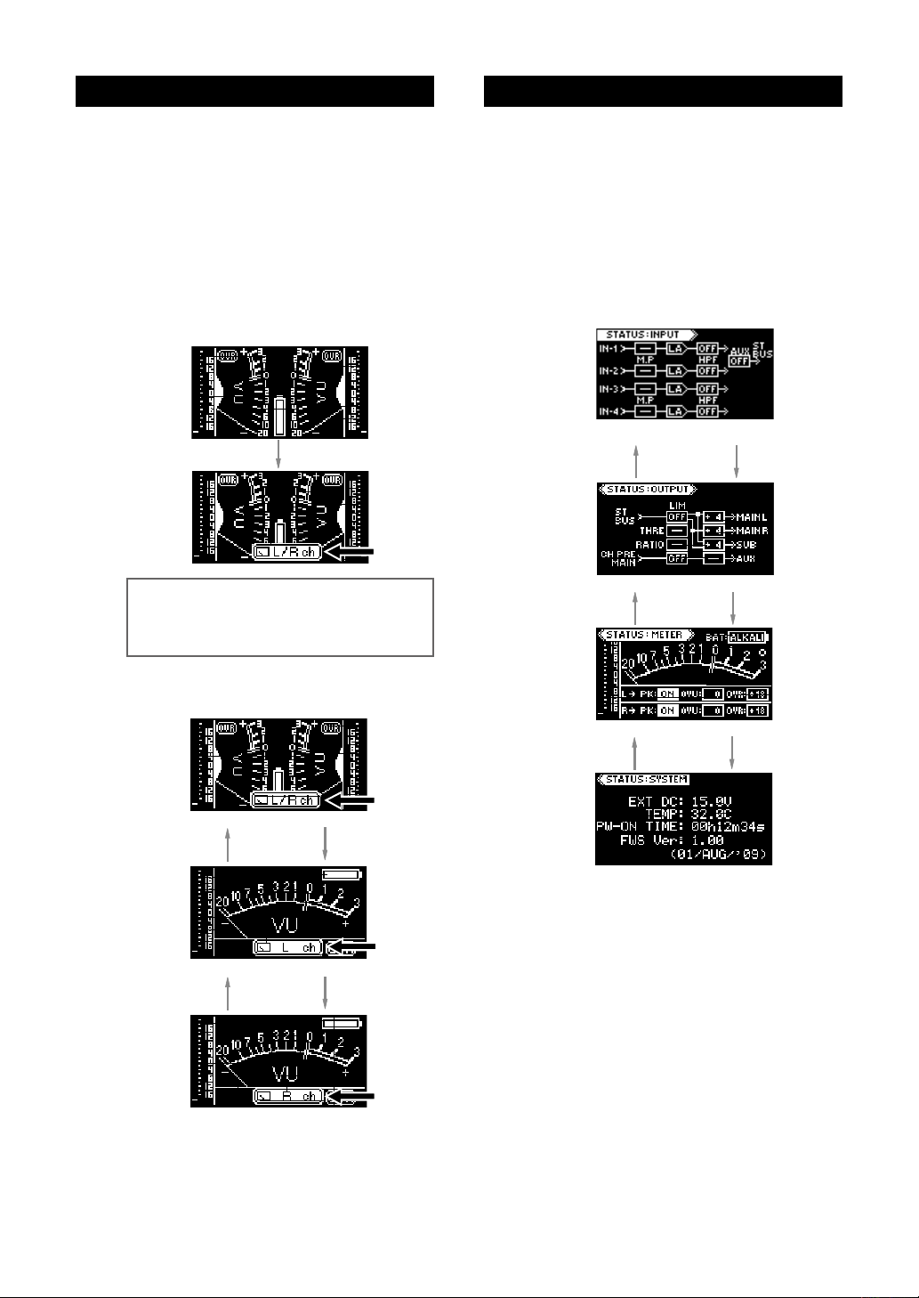
Selecting the meter mode
Selecting the status display
You can select the meter mode from stereo, mono
L and mono R. By default, it is set to the stereo
mode.
The meter mode setting remains even after you
turn off the unit. If you initialize the flash memory
using the system status display, it is reset to the
default setting (see page 24).
(1) Press the [METER] key long enough to enter
the meter select mode.
The meter mode icon is shown at the bottom of the
display.
<Memo>: If you do not press any key for approximately five seconds while the meter mode
icon is shown, the icon automatica lly disap
pears and the unit exits the meter select mode.
-
In the status display mode, not only you can check
the status for the input, output, meter and system,
but also you can edit setting.
(1) Press the [STATUS] key long enough to enter
the status display mode.
The display shows the input status display.
(2) Press the [+] or [-] key to select the desired
status display.
Input status display
Press the [-] key
Output status display
Press the [-] key
Press the [+] key
Press the [+] key
(2) Press the [+] or [-] key to select the desired
meter mode.
Stereo meter mode
Press the [-] key
Mono meter (L) mode
Press the [-] key
Mono meter (R) mode
Press the [+] key
Press the [+] key
(3) Immediately after selecting the desired meter
mode, press the [EDIT] key to exit the meter
select mode.
Meter status display
Press the [-] key
System status display
Press the [+] key
(3) Press the [EDIT] key to exit the status display
mode.
For details about the contents of each status dis-
play and parameter setting, see the next page.
18
Page 19
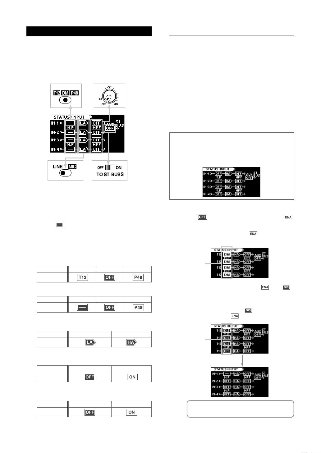
Input status display
130
60
On the input status display, not only you can see the
current status of the following switches, but also you
can disable or enable the T12 power supply function.
The following shows the default setting when the unit
is shipped.
Left side panel
Front panel
T12 disabled/enabled setting
Some condenser microphones used for video field
recording, such as the Sennheiser 416T, require
T12 (AB-12V) power. The FM-4 can supply the T12
power.
Unlike the phantom power (P48), connecting a
dynamic microphone to the input channel where
the T12 power is supplied may destroy the mi
crophone. To prevent such an accident, you can
disable the T12 power supply function. If you do
not use the T12 power supply function in your cir
cumstance, it is recommended to disable the T12
power by following the procedure below. When
shipped, the T12 power supply function is en
abled.
<Note>: In the following description, it is assumed that
the input select switches (LINE / MIC) are set to “MIC”
and the Microphone power supply switches are set to
“DM” on the left side panel. In this condition, the input
status display looks as below.
-
-
-
Left side panel
Left side panel
The fol lowing ico ns are shown acco rdi ng to the
switch setting.
• Microphone power supply switch status
When the input select switch (LINE / MIC) is set to
“LINE”, “ ” is shown. When it is set to “MIC”, the
microphone power supply status is shown.
For the T12 status, depending on whether the T12
power supply function is enabled or disabled, the icon
looks differently as below.
When the T12 power supply function is enabled (default)
Switch setting
Icon
When the T12 power supply function is disabled
Switch setting
Icon
T12 DM P48
T12 DM P48
• Input select switch status
Switch setting
Icon
• [HPF] switch status
Switch setting
Icon
LINE
OFF
MIC
ON (40 Hz - 200 Hz)
(1) While the input status display is shown, press
the [EDIT] key long enough.
The “ ” icons change to the fast flashing “ ”
icons.
You can now edit enabled/disabled setting of the
T12 power supply function. (“
setting, which is the default.)
Flashing
” shows “Enable”
(2) Press the [+] key to change “ ” to “ ”,
and press the [EDIT] key long enough.
The T12 power supply function is now disabled.
The display returns to the previous condition. (If you
press the [-] key while the “
they are changed to “
Flashing
” icons are flashing,
”.)
• [TO ST BUSS] switch status
Switch setting
Icon
OFF
ON
<Memo>: The T12 disabled/enabled setting re-
mains even after you turn off the unit.
19
Page 20
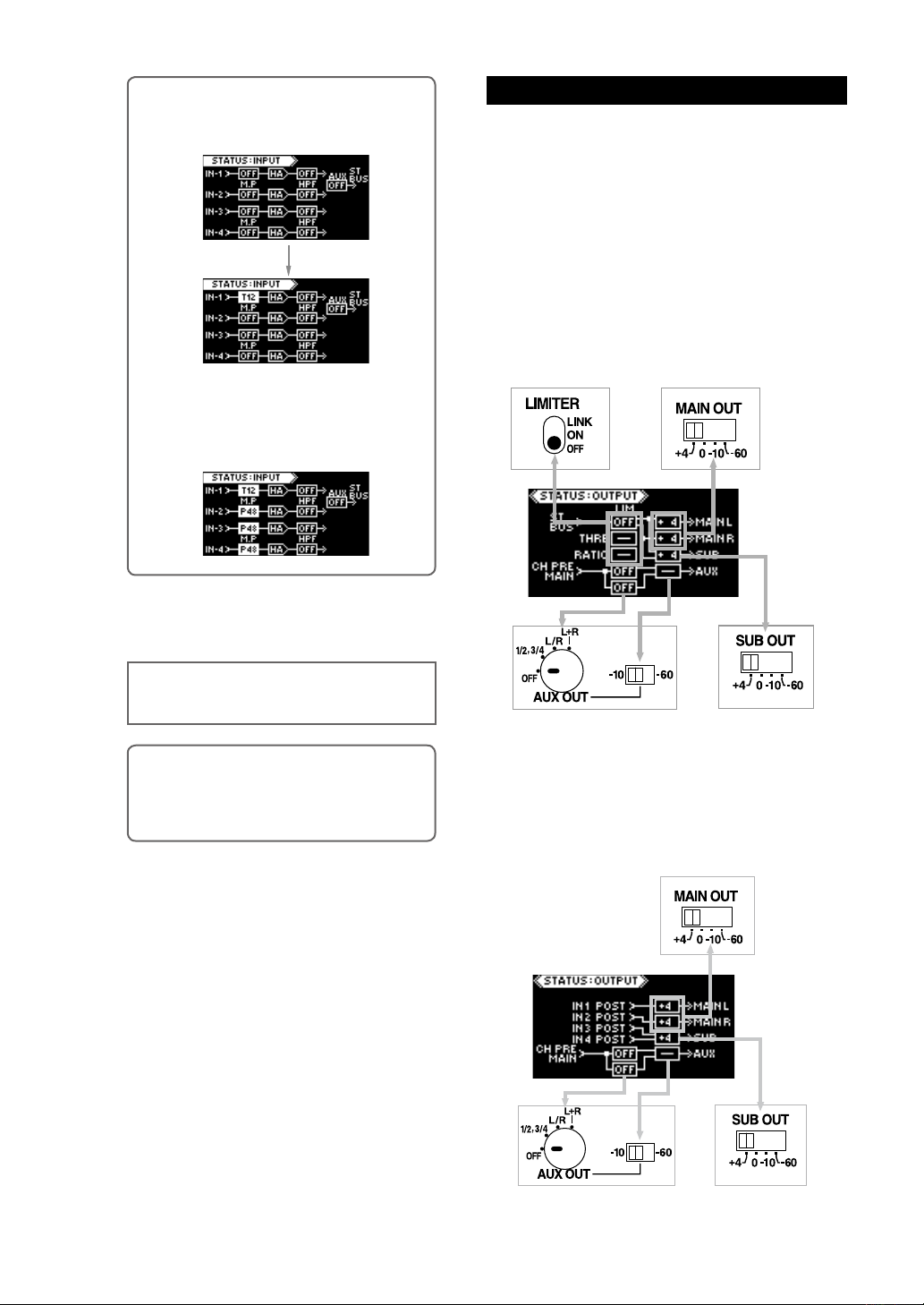
<Memo>: If you switch the microphone power
supply switch of INPUT 1 to “T12”, the input
status display changes as below.
If you set the microphone power supply switch
of INPUT 1 to “T12” and set the microphone
power supply switches of INPUT 2 through IN
PUT 4 to “P48”, the input status display looks
as follows.
-
(3) Press the [EDIT] key to exit the status display
mode.
The display changes to the meter display.
Output status display
On the output status display, you can see the current
status of the switches related to the outputs as well
as the output sources.
Depending on the [SOURCE SEL] switch setting, the
display looks as below.
When the [SOURCE SEL] switch is set to “MIX”
The display shows the status of the switches shown
below, as well as the output sources. The following
shows the default setting when the unit is shipped.
You can set the threshold and ratio of the limiter from
this display.
Front panel
Right side panel
<Note>: If you need to supply the T12 power,
set the T12 power supply function to “ENA” by
the similar procedure as above.
<Memo>: The T12 disabled/enabled setting remains even after you turn off the unit. However,
if you initialize the flash memory using the sys
tem status display, it is reset to the default “ENA”
setting (see page 24).
Right side panel
Right side panel
When the [SOURCE SEL] switch is set to “DIRECT
OUT”
-
The display shows the status of the switches shown
below, as well as the output sources. The following
shows the default setting when the unit is shipped.
Right side panel
Right side panel
Right side panel
20
Page 21
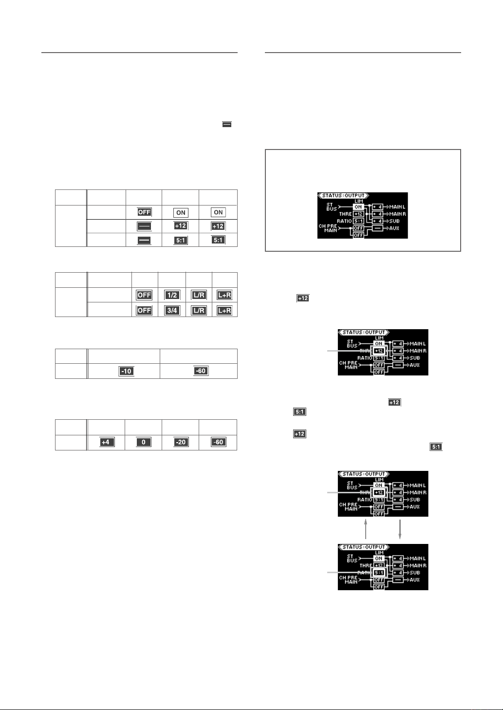
Status information details
Limiter parameter setting
The following icons are shown according to the switch setting.
• [LIMITER] switch status
When the [LIMITER] switch is set to “OFF”, the parameter boxes for the threshold and ratio show “
When the [LIMITER] switch is set to “ON” or “LINK”,
the paramete r boxes for the threshold and ratio
show the current parameter values.
You can edit the parameter values by following the
procedure described in the next page.
Switch
setting
Icon
THRE
RATIO
OFF
ON
LINK
• AUX OUT switch status
Switch
setting
Icon
Upper (AUX 1)
Lower (AUX 2)
OFF
1/2 , 3/4 L/R L+R
• AUX OUT level switch
Switch
setting
Icon
-10
-60
By setting the [LIMITER] switch to “ON” (or “LINK”),
the limiter function is enabled and you can apply
the limiter to the stereo L/R buss.
The threshold level and ratio (compression ratio) of
”.
the limiter are set to “+12” and “5.1” respectively
by default.
<Note>: In the following description, it is assumed
that the [LIMITER] switch on the front panel is set to
“ON” and the input status display looks as below.
(1) While th e output status displa y is shown,
press the [EDIT] key long enough.
“ ”, the cu rre nt TH RE va lue, start s fla shing
quickly.
You can now edit the threshold level.
Flashing
• SUB OUT level switch
• MAIN OUT (L, R) level switches
Switch
setting
Icon
+4
0
-10 -60
(2) By pressing the [EDIT] key, you c an alt er
nately flash the THRE (“ ”) and RATIO (“
To edit the threshold level, flash the THRE value (“
”) values.
”).
To edit the ratio, flash the RATIO value (“ ”).
Flashing
Flashing
-
21
Page 22
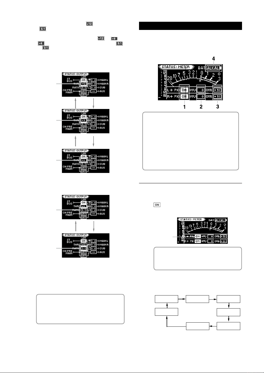
(3) While the THRE value (“ ”) or the RATIO
(“ ”) is flashing, use the [+] or [-] key to
select the desired value.
You can set the THRE value to “ ”, “ ” or
“ ”, while you can set the RATIO value to “ ”
or “
”.
To select the threshold value:
Flashing
Press the [-] keyPress the [+] key
Meter status display
On the meter status display, not only you can see the
current status of the metering, but also you can set
parameters. The following shows the default setting
when the unit is shipped.
Flashing
Press the [-] keyPress the [+] key
Flashing
To select the ratio:
Flashing
Press the [-] keyPress the [+] key
Flashing
(4) After selecting the desired value, press the
[EDIT] long enough to stop flashing.
(5) Press the [EDIT] key to exit the status display
mode.
(1) Peak meter ON/OFF
You can enable or disable the peak meter function for the left and right
channels independently.
(2) VU meter reference (0 VU) level
You can set the reference level for the left and right channels independently.
(3) Threshold level of the peak over indicator
You can set the peak threshold level for the left and right channels
independently.
(4) Internal battery type
You can set the battery type between alkaline or nickel hydride.
Parameter setting procedure
(1) Wh ile the meter st atus di splay is sh own,
press the [EDIT] key long enough.
The peak meter on/off setting of the left channel (“
”) starts flashing. You can now edit the peak
meter on/off setting of the left channel.
Flashing
<Memo>: By bringing up the meter status
display while the unit is receiving a signal, you
can edit parameters while checking movement of the VU and peak meters.
(2) While any parameter is flashing, press the
[EDIT] key to select the flashing parameter.
Pressing the [EDIT] key selects the flashing pa-
rameter in the following order.
<Memo>: The limiter parameter setting remains even after you turn off the unit. If you
initialize the flash memory using the system
status display, it is reset to the default setting
(see page 24).
22
Lch “PK”
BAT TYPE
Lch “0VU” Lch “OVR”
Rch “PK”
Rch “0VU”Rch “OVR”
Page 23
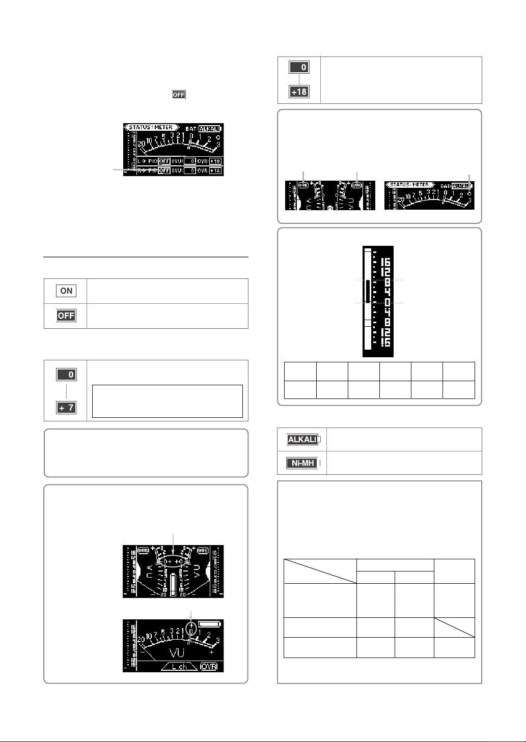
(3) While the desired parameter to be edited is
flashing, you can select a desired value using
the [+] or [-] key.
In the following display example, both the left a
right peak meters are set to “
”.
See “Parameter details” below for the available op
tions of each parameter.
Flashing
(4) After editing parameters, press the [EDIT] key long
enough to stop flashing.
(5) Press the [EDIT] key to exit the status display mode.
Parameter details
Lighting level of peak over indicator
The default is “+18 dB”. You can select between “0
dB” and “+18 dB” in 1 dB steps.
-
<Memo>: When peak level exceeds the lighting level,
“OVER” is lit on the stereo meter display, as pointed
by an arrow in the stereo meter display example below
left. On the meter status display, “0” is lit as pointed by
an arrow in the display example below right.
Lit Lit
Stereo meter display
Meter status display
Lit
<Memo>: The details of the peak meter is as below.
Peak meter on/off
The meter display shows both VU and peak metering (default).
The meter display shows only VU metering. The peak me
tering is not shown.
VU meter reference level
The default value is “0 dB”. You can select between “0
dB” and “+7 dB” in 1 dB steps.
<Example>: If you set the reference level to “+5”,
the level at 0 VU is +5 dB higher than the refer
ence level.
<Memo>: It is recommended to change the reference level appropriately when an external audio device connected to the outputs of the unit has enough
headroom. Normally, set it to “0”.
<Memo>: If you set the reference level other than
“0”, “+” is lit beside the “0” position of the VU meter,
showing that the 0 VU level is not the reference level.
+
Stereo VU meter
+
Left channel VU meter
Permitted Level
-
Alignment Level (AL)
Scale
-16 to +16
(Reference)
AL
Level
@
PML
Level
@+9dB
-
+13dBu (+9dB)
+4dBu (reference level)
Attack
Time
0.1msec.
Fall
Time
1.7sec/
20dB
Peak Hold
Time
2sec.
Internal battery selection
When you use alkaline batteries, select this option.
When you use nickel hydride batteries, select this
option.
<Note>: This setting allows the EMPTY indicator and the
alert for battery exchange work correctly according to the
battery type. When you operate the unit on internal battery
power, this item should be set correctly. Battery life depends
on the battery type, battery condition and usage environment. It is recommended to exchange batteries when the
EMPTY indicator starts flashing.
EMPTY indicator flashing
condition (approximately 30
minutes before batteries are
completely exhausted)
Alert for battery exchange*
Audio mute
Alkaline
Less than
8.1 V
Less than
7.5 V
Less than
6.1 V
INT DC
Ni-MH
Less than
9.2 V
Less than
8.6 V
Less than
6.1 V
EXT DC
Less than
7.0 V
Less than
6.1 V
23
* “Please change battery!” is shown as alert for battery exchange.
Page 24
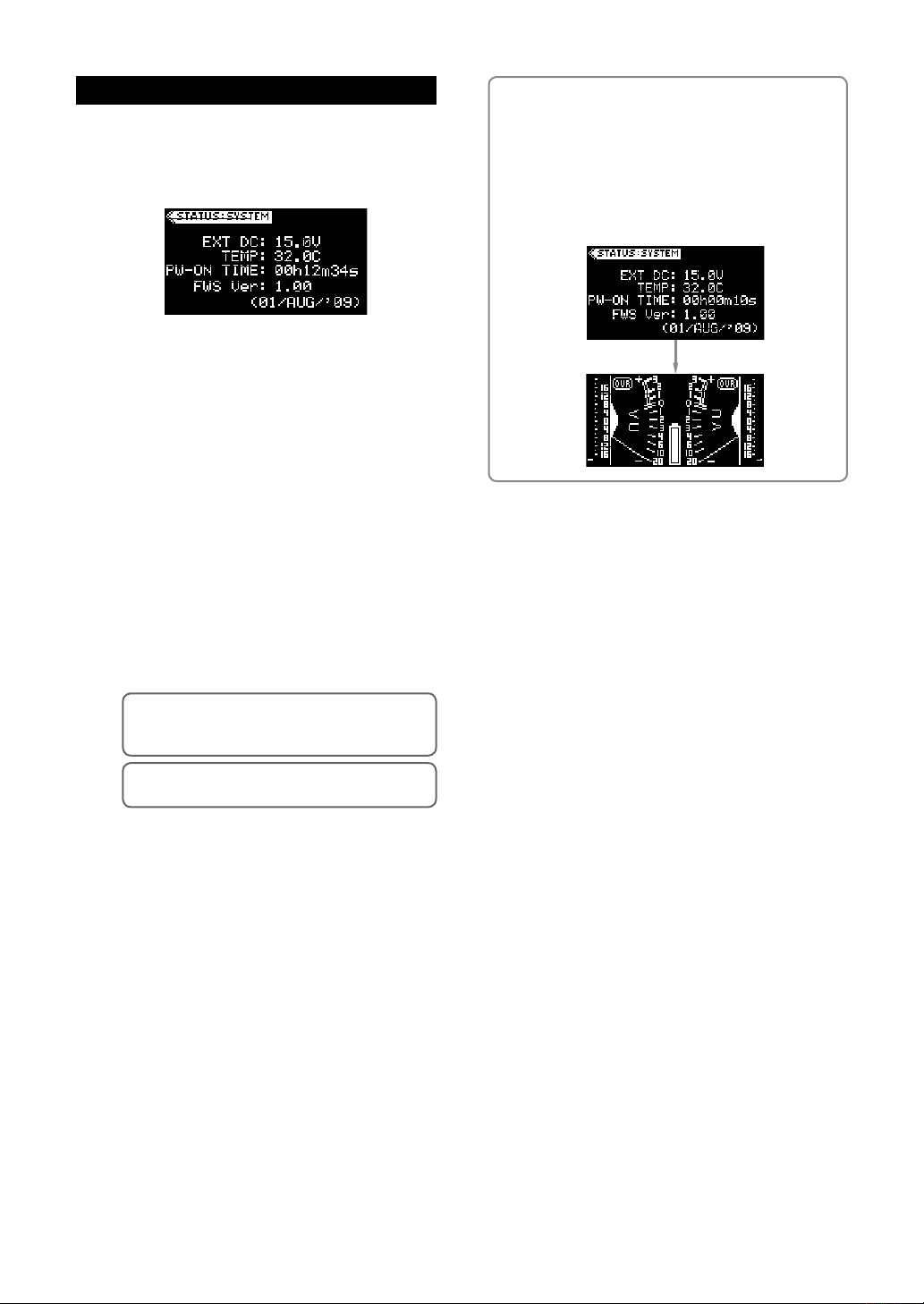
System status display
On the system status display, not only you can see
the following information, but also you can reset the
time display and initialize the flash memory.
(1) Power voltage (EXT DC or INT DC)
This item shows the voltage of the current power
source.
When the [POWER] switch is set to “INT”, this item
shows “INT DC” and the voltage of the internal bat
teries.
When the [POWER] switch is set to “EXT”, it shows
“EXT DC” and the voltage of the exter nal power
source.
(2) Temperature inside the unit (TEMP)
This item shows the temperature inside the unit.
The temperature significantly affects the battery
performance.
Generally, in a low temperature environment, the
battery life of primary battery (e.g. alkaline) gets
shorter.
Initializing the flash memory
You can initialize the flash memory to the condition when
the unit is shipped from the factory. To initialize the flash
memory, press and hold down the [EDIT] key for 10 seconds or more while the system status display is shown.
When the memory initialization is completed, the system
status display is dismissed and the display shows the
stereo VU meter display.
-
(3) Power-on time
This item shows the elapsed time since the unit is
powered on. The time display is running in realtime.
<Memo>:
while the system status display is shown, you can
reset this item to “00h00m00s”.
<Memo>:
“00h00m00s” after powering off the unit.
By pressing the [EDIT] key long enough
The time display is automatically reset to
(4) Firmware version
This item shows the firmware version of the unit.
24
Page 25

Specifications
Inputs/Outputs
* 0dBu = 0.775Vrms
<Analog Inputs>
[INPUT] 1 through [INPUT] 4
• Connector: XLR-3-31 type (transformer balanced)
<LINE input>
• Input impedance: 10 k
• Nominal input level: -20 dBu to +4 dBu
• Maximum input level: +29 dBu
<MIC input>
• Input impedance: 2 k
• Nominal input level: -70 dBu to -30 dBu
• Maximum input level: -5 dBu
[AUX IN]
• Connector: XLR-5-51 type (electronically balanced)
• Input impedance: 20 k
• Nominal input level: +4 dBu
• Maximum input level: +29 dBu
[RTN]
• Connector: 3.5mm stereo mini-phone jack (unbalanced)
• Input impedance: 10 k
• Nominal input level: -10 dBV
• Maximum input level: +15 dBV
or more
Ω
or more
Ω
or more
Ω
or more
Ω
[PHONES]
• Connectors:
1/4” stereo phone jack and 3.5 mm stereo
mini-phone jack
• Applicable load impedance: 8
• Maximum output power:
50 mW (at 32
load, THD: 0.1 % or less)
Ω
or more
Ω
<Others>
[DC IN]
• Connector: XLR-4-32 type (male)
• Input voltage: DC 10 V to DC 24 V
[DC OUT]
• Connector: Hirose 4 pin (female)
* Applicable plug: Hirose HR10A-7P-4P
• Output voltage: DC 7.2 V - 24 V (Max. 0.5 A)
Performance
Frequency response
• LINE IN - MAIN OUT:
20 Hz to 20 kHz +/- 1 dB (reference level)
• MIC IN - MAIN OUT:
40 Hz to 20 kHz +/- 1 dB (reference level)
<Analog Outputs>
[MAIN OUT] (L/1, R/2)
• Connector: XLR-3-32 type (transformer balanced)
• Applicable load impedance: 600
• Nominal output level: +4, 0, -10 or -60 dBu (switchable)
• Max imu m output leve l: +24, +20, +10 or -40 dBu
(switchable)
[SUB OUT] (L/3, R/4)
• Connector: XLR-3-32 type (electronically balanced)
• Applicable load impedance: 10 k
• Nominal output level: +4, 0, -10 or -60 dBu (switchable)
• Maximum output level: +24, +20, +10 or -40 dBu (switchable)
[TAPE OUT]
• Connector: 3.5mm stereo mini-phone jack (unbalanced)
• Applicable load impedance: 10 k
• Nominal output level: -10 dBV
• Maximum output level: +10 dBV
[AUX OUT] (1, 2)
• Connector: 3.5mm stereo mini-phone jack (unbalanced)
• Applicable load impedance: 10 k
• Nominal output level: -10 dBV or -60 dBV (switchable)
• Maximum output level: +10 dBV or -40 dBV (switchable)
or more
Ω
or more
Ω
or more
Ω
or more
Ω
• HEADPHONES (32
20 Hz to 20 kHz +/- 3 dB
load, 25 mW output power):
Ω
S/N ratio (A-weighted)
• LINE (INPUT GAIN: +4 dBu): 80 dB or better
• MIC (INPUT GAIN: -70 dBu: 55 dB or better
(equivalent input noise: -125 dBu)
Total harmonic distortion
0.1% or less at 1 kHz
Headphones residual noise
-72 dBV or less (A-weighted)
(PHONES level control at minimum)
Crosstalk:
-70 dB or less at 1kHz
25
Page 26
Others
Phantom power:
P48 (phantom 48 V) and T12 (A-B 12 V) power supply
circuit for each input channel.
* T12 power supply can be disabled or enabled using
the status mode.
HPF (High pass filter)
40 Hz to 200 Hz, -12 dB/oct.
The cutoff frequency is continuously sweepable.
EQ (equalizer):
• HI:
Type: Shelving
Cutoff frequency: 10 kHz (fixed)
Boost/cut range: -12 dB to +12 dB
• MID:
Type: Sweepable
Center frequency: 200 Hz to 8 kHz (sweepable)
Boost/cut range: -12 dB to +12 dB
Slate microphone / slate tone
Slate tone: 1kHz
Slate microphone: built in the unit
Level meter
VU and peak level meters
Stereo/mono metering selectable
Limiter
Attack time: approximately 5 msec.
Release time: approximately 200 msec.
Threshold level: +6 dB, +9 dB or +12 dB
Ratio: 3:1 or 5:1
* Threshold level and ratio can be selected using the
status mode.
General
External dimensions:
274 (W) x 57 (H) x 180 (D) mm (Including protrusions)
Weight:
Approximately 1.5 kg (not including battery box)
Approximately 1.7 kg (includi ng the battery box and
eight AA alkaline batteries)
Power:
Int ernal batteries: Eight AA batte ries ( alka line: 12 V,
nickel hydride: 9.6 V)Power requirement: DC 7.2 to 12 V
External power supply: Optional AC adaptor
Recommended external battery voltage: DC12 to 24V
Power requirement: DC10 to 24 V
Power consumption:
Approximately 4.0 W
Operation condition:
Temperature: -10 ºC to +50 ºC
Humidity: 85% or less (no moisture condensation)
Supplied accessories:
Battery box, Owner’s manual
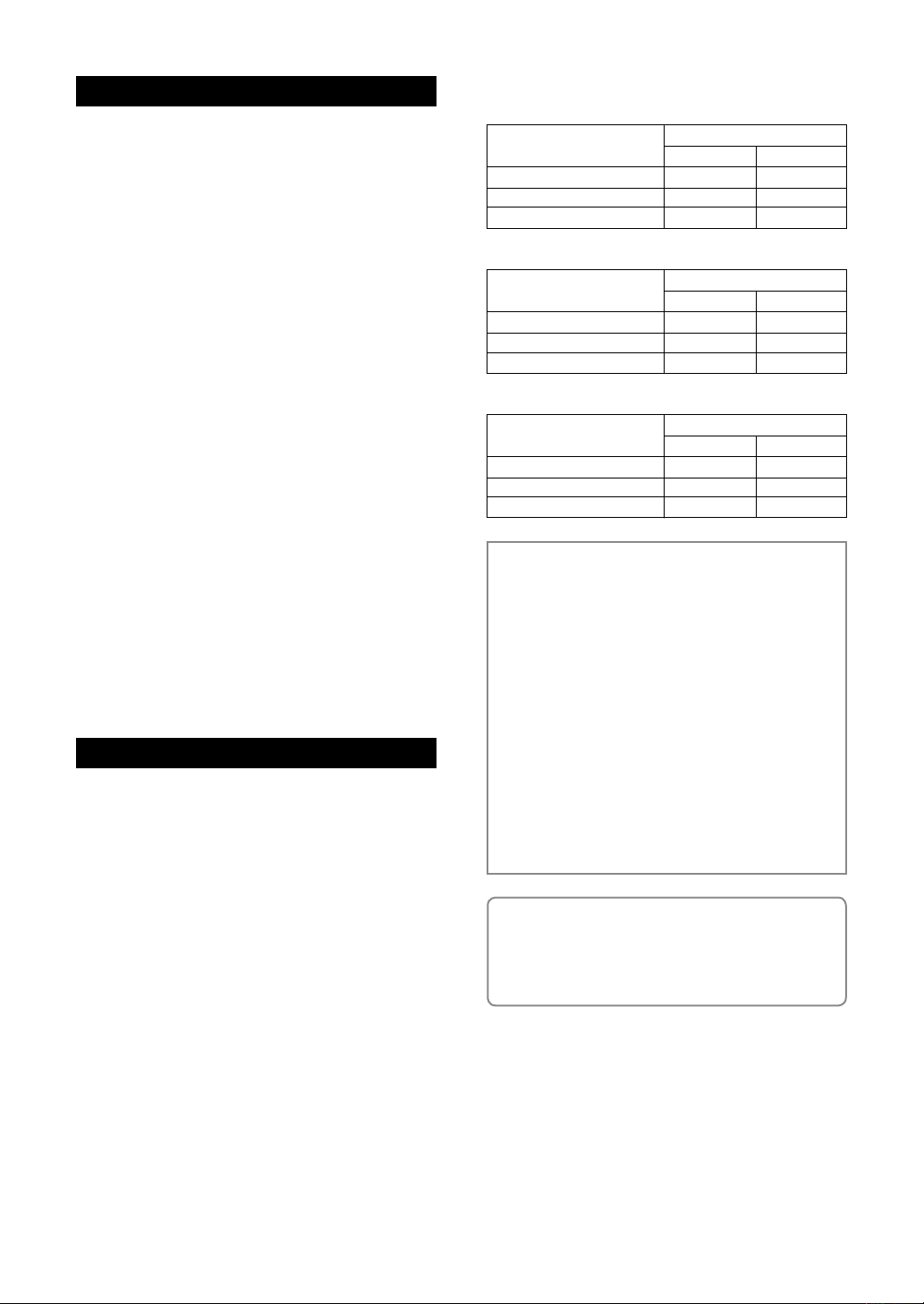
Operation time with batteries (for reference)
Measurement condition: 20º C temperature, 60% humidity
Battery type
Alkakine (LR6)
Ni-MH (SANYO eneloop)
Ni-MH (SANYO 2700mAh)
Measurement condition: 0º C temperature, saturated humidity
Battery type
Alkakine (LR6)
Ni-MH (SANYO eneloop)
Ni-MH (SANYO 2700mAh)
Measurement condition: +45º C temperature, 60% humidity
Battery type
Alkakine (LR6)
Ni-MH (SANYO eneloop)
Ni-MH (SANYO 2700mAh)
<Note 1>: The operation time data shown above is
for reference only. The actual operation time depends
on the operational condition or circumstance.
<Note 2>: The more time the nickel hydride battery
is charged or discharged, the maximum capacity decreases.
<Note 3>: The data shown above is measured using
nickel hydride batteries that has been fully charged
just before. Because a nickel hydride battery self-discharges, it is recommended to charge nickel hydride
batteries just before using. Also it is recommended to
use batteries whose self-discharge rate is low (e.g.,
SANYO eneloop).
<Note 4>: Use eight batteries of the same type and
same capacity.
<Memo>: Lower the operation temperature is, shorter the life of a primary battery (e.g alkaline) is.
When you use the unit in a place where temperature
is low, it is recommended to use nickel hydride batteries.
* Spe cifi cations and app eara nce are subj ect to change
without notice for product improvement.
Microphone power supply
OFF (DM)
Approx. 5.5 hours
Approx. 6.5 hours
Approx. 7.5 hours
Microphone power supply
OFF (DM)
Approx. 2.5 hours
Approx. 6.5 hours
Approx. 7.5 hours
Microphone power supply
OFF (DM)
Approx. 7.0 hours
Approx. 7.0 hours
Approx. 8.0 hours
ON (P48 x 3)
Approx. 4.5 hours
Approx. 5.5 hours
Approx. 7.0 hours
ON (P48 x 3)
Approx. 2.0 hours
Approx. 5.5 hours
Approx. 6.5 hours
ON (P48 x 3)
Approx. 5.5 hours
Approx. 5.5 hours
Approx. 7.0 hours
26
Page 27
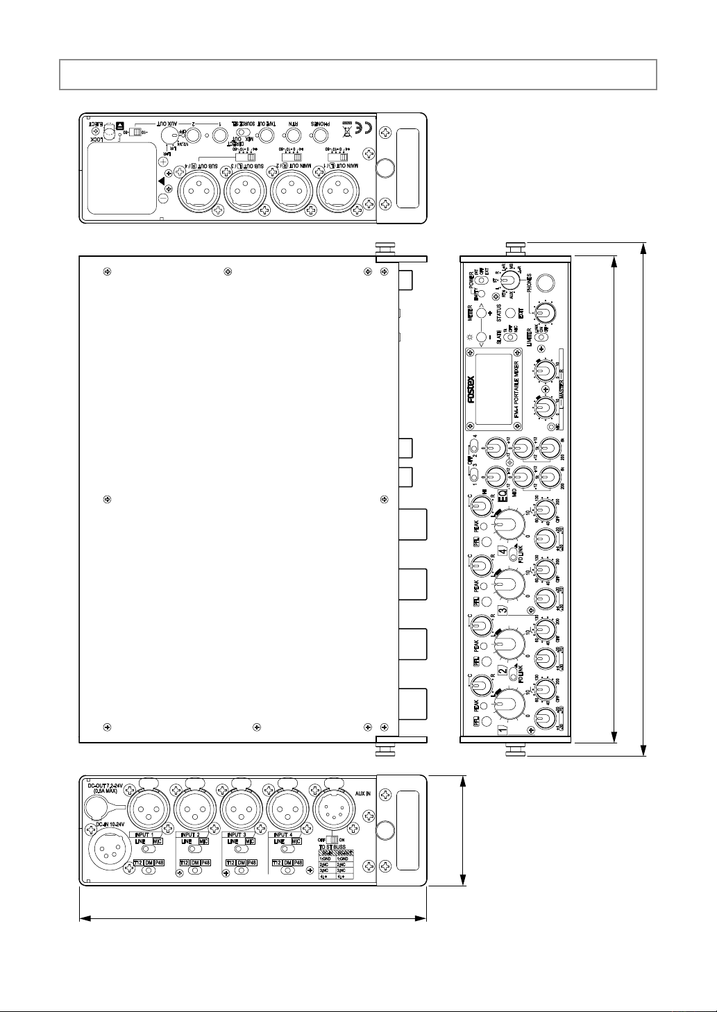
External dimensions
274
252
180
57
27
Page 28

Memo
28
Page 29

Declaration of EC Directive
This equipment is compatible with the EMC Directive (2004/108/EC) - Directive on approximation of member
nation's ordinance concerning the electromagnetic compatibility and with the Low Voltage Directive (73/23/
EEC) - Directive on approximation of member nation's ordinance concerning electric equipment designed to be
used within the specified voltage range.
The Affect of Immunity on This Equipment
The affect of the European Specification EN61000-6-1 (coexistence of electromagnetic waves - common immunity
specification) on this equipment are as shown below.
In the electrical fast transient/burst requirements, surge, conducted disturbances by radio-frequency fields, power
frequency magnetic field, radiate electromagnetic field requirements and static electricity discharging environment, this
could be affected by generation of noise in some cases.
FOSTEX DISTRIBUTORS LIST IN EUROPE
* Including non-EU countries (as of June 2009)
<AUSTRIA>
NAME: ATEC Audio-u. Videogeraete VertriebsgesmbH.
ADD: Im Winkel 5, A-2325 Velm, Austria
TEL: (+43) 2234-74004, FAX: (+43) 2234-74074
<BELGIUM>
NAME: General Audio
ADD: Raymond Pelgrimslaan 101, B-1702 GrootBijgaarden, Belgium
TEL: (+32) 2-4630650, FAX: (+32) 2-4661500
<DENMARK>
NAME: Benum Nordic A/S
ADD: Meterbuen 18, Skovlunde, 2740 Denmark
TEL: (+45) 4451-8900, FAX: (+45) 4451-8911
<FINLAND>
NAME: Noretron Oy Audio
ADD: P. O. Box 22, FIN-02631 Espoo, Finland
TEL: (+358) 9-5259330, FAX: (+358) 9-52593352
<FRANCE>
NAME: Sennheiser France
ADD: 128 bis, avenue Jean-Jaures, 94851 Ivry-sur-Seine
Cedex, France
TEL: (+33) 1 4987 0300, FAX: (+33) 1 4987 0324
<GERMANY>
NAME: Mega Audio GmbH
ADD: Stromberger Str. 32, D-55411 Bingen, Germany
TEL: (+49) 6721-94330, FAX: (+49) 6721-32046
<GREECE>
NAME: Bon Studio S. A.
ADD: 6 Zaimi Street, Exarchia, 106.83 Athens, Greece
TEL: (+30) 210-3809-605, 606, 607, 608
FAX: (+30) 210-3845-755, 210-3827-868
<ICELAND>
NAME: I. D. elrf. electronic Ltd.
ADD: ARMULA 38 108 REYKJAVIK, ICELAND
TEL: (+354) 588 5010, FAX: (+354) 588 5011
<ITALY>
NAME: Proel S. p. A.
ADD: Zona Via Alla Ruenia, 37/43 64027 - Sant’Omero
(Teramo), Italy
TEL: (+39) 0861-81241, FAX: (+39) 0861-887862
<THE NETHERLANDS>
NAME: IEMKE ROOS AUDIO B. V.
ADD: Kuiperbergweg 20, 1101 AG Amsterdam, The
Netherlands
TEL: (+31) 20-697-2121, FAX: (+31) 20-697-4201
<NORWAY>
NAME: Siv. Ing. Benum AS
ADD: P. O. Box 145, Vinderen, 0319 Oslo, Norway
TEL: (+47) 2213 9900, FAX: (+47) 2214 8259
<SPAIN>
NAME: Letusa S. A.
ADD: C/Laguna 10, 28923 Alcorcon, Madrid, Spain
TEL: (+34) 91-4862800, 91-4470898, FAX: (+34)
91-6414597
<SWEDEN>
NAME: Benum Nordic A/S
ADD: Aldermansvagen 17, 171 48 Solna, Sweden
TEL: (+46) 8 207710
<SWITZERLAND>
NAME: Audio Bauer Pro AG
ADD: Bernerstrasse-Nord 182, CH-8064 Zurich,
Switzerland
TEL: (+41) 1-4323230, FAX: (+41) 1-4326558
<UK>
NAME: SCV London
ADD: 40 Chigwell Lane, Oakwood Hill Industrial Estate,
Loughton, Essex IG10 3NY U. K.
TEL: (+44) 20-8418-0778, FAX: (+44) 20-8418-0624
29
Page 30

FOR THE US CUSTOMERS ONLY
FOSTEX AMERICA LIMITED WARRANTY
The following statement denes specic legal rights. You may also have additional rights depending on
the state in which the Fostex product was purchased.
WARRANTY PROTECTION
All Fostex parts are warranted for one (1) year from the date of original purchase, except for recording
media, such as hard disc drives and compact ash cards, heads, lamps and fuses, which are warranted,
for one hundred-eighty (180) days. Fostex America will repair and / or replace parts during the term of
this warranty. Labor costs are also covered by Fostex America for one (1) year from the date of original
purchase. Except as specied below, this warranty covers all defects in material and workmanship in this
product.
The following are not covered by this warranty:
1. Batteries.
2. Damage to any product that has been altered.
3. Damage to any product on which the original serial number has been defaced, modied or
removed.
4. Damage to or deterioration of the external cabinet.
5. Damage occurring during shipment of the product. (NOTE: Shipping claims must be
presented to the carrier.)
6. Damage resulting from accident, misuse, abuse or neglect.
7. Damage resulting from failure to perform routine maintenance and / or calibration
procedures.
8. Damage resulting from failure to follow instruction in the owner's manual.
9. Damage resulting from repair or attempted repair or by someone other than a Fostex America
Service technician or a technician at an authorized Fostex America service station.
10. Damage resulting from causes other than product defects, including lack of technical skill,
competence or experience on the part of the user.
11. External appearance items such as cosmetic parts, knobs, liquid crystal displays, buttons, etc.
12. Replacements or repairs necessitated by loss or damages resulting from any cause beyond the
control of Fostex America.
13. Damage resulting from misuse or abuse on rental units.
NOTE: FOSTEX AMERICA IS NOT RESPONSIBLE FOR DATA LOST OR DAMAGED DURING
OPERATION OF THIS PRODUCT.
CALIBRATION AND MAINTENANCE PROCEDURES ARE NOT COVERED BY THIS WARRANTY.
Fostex America reserves the right to inspect all products submitted pursuant to this warranty.
If such an inspection shows reasonable cause to believe that any of the above exclusions to the above
warranty are applicable, then Fostex America or the authorized service station will charge prevailing service rates and parts, costs for any repairs.
30
Page 31

FOSTEX AMERICA LIMITED WARRANTY
To claim all warranty service, rst access www.fostex.com to receive service authorization (RMA number).
Then present the authorization together with the bill of sale, which shows the date of original purchase to
Fostex America. This warranty is not transferable.
SHIPPING
If this product needs service, you must take it, or package it carefully, using ample packaging materials to
prevent damage during shipment and mail it to the distributor from whom you have purchased this product, postage pre-paid and insured.
occurred in transit, but will reasonably assist the sender in processing any claims whenever possible (such as
submitting statements to the carriers when applicable).
Any collect or C.O.D. shipments will be refused. In order to obtain warranty repairs, you must include the
following:
1. Date proof of original purchase (copy of bill of sale or charge slip).
2. A note describing the problem with sufcient particularity to allow Fostex America to inspect
or adjust the problem.
3. All accessory items appurtenant to that problem.
LIMITATIONS OF IMPLIED WARRANTIES AND EXCLUSIONS OF CERTAIN DAMAGES
NOTE:
Fostex America will not assume responsibility for damages or losses
Unless considered unenforceable or unlawful under applicable law:
A. All implied warranties - including warranties of merchantability and tness for a particular
purpose -are limited in duration to term of this warranty and to the express coverage of this
warranty;
B. Fostex America's liability for any defect product is expressly limited to repair or replacement
of the product, at the sole discretion and / or option of Fostex America.
Fostex America shall not under any circumstances be liable for:
1. Damaged based on inconvenience, loss of use of the product, loss of time,
interrupted operation or commercial loss, OR;
2. Any damages, whether incidental, consequential or otherwise, except damages
which may not be excluded by under applicable law.
C. Fostex America makes no other warranties, express or implied, above and / or beyond the
representations made herein.
WARRANTY APPLIES ONLY TO THOSE PRODUCTS SOLD AND DISTRIBUTED BY FOSTEX AMERICA
Service Department
FOSTEX AMERICA
Please visit www.fostex.com for the latest contact information.
31
Page 32

FOSTEX CO.
3-2-35, Musashino, Akishima-shi, Tokyo Japan, 196-0021
32
© PRINTED IN JAPAN JULY 2009 8289670000
505068
 Loading...