

Page 1

Service Manual
Model
FD-8
DIGITAL MULTITRACKER
Page 2
CAUTION
RISK OF ELECTRIC SHOCK
DO NOT OPEN
CAUTION:
TO PREVENT ELECTRIC SHOCK, MATCH
WIDE BLADE OF PLUG TO WIDE SLOT,
FULLY INSERT.
CAUTION: TO REDUCE THE RISK OF ELECTRIC SHOCK,
DO NOT REMOVE COVER (OR BACK).
NO USER-SERVICEABLE PARTS INSIDE.
REFER SERVICING TO QUALIFIED SERVICE PERSONNEL.
The lightening flash with arrowhead symbol,
within an equilateral triangle, is intended to
alert the user to the presence of uninsulated
“dangerous voltage” within the product's enclosure that may be of sufficient magnitude to
constitute a risk of electric shock to persons.
“WARNING”
“TO REDUCE THE RISK OF FIRE OR ELECTRIC SHOCK,
DO NOT EXPOSE THIS APPLIANCE TO RAIN OR MOISTURE.”
SAFETY INSTRUCTIONS
Read instructions - All the safety and operating instruc-
1.
tions should be read before the appliance is operated.
Retain instructions - The safety and operating instructions
2.
should be retained for future reference.
Heed warnings - All warnings on the appliance and in the
3.
operating instructions should be adhered to.
Follow instructions - All operating and use instructions
4.
should be followed.
Water and Moisture - The appliance should not be used
5.
near water - for example, near a bathtub, washbowl,
kitchen sink, laundry tub, in a wet basement, or near a
swimming pool, and the like.
Carts and Stands - The appliance should be used only
6.
with a cart or stand that is recommended by the manufacturer.
An appliance and cart combination should be moved with
care. Quick stops, excessive force, and uneven surfaces
may cause the appliance and cart combination to overturn.
Wall or Ceiling Mounting - The appliance should be
7.
mounted to a wall or ceiling only as recommended by the
manufacturer.
Ventilation - The appliance should be situated so that its
8.
location or position does not interfere with its proper ventilation. For example, the appliance should not be situated on a bed, sofa, rug, or similar surface that may block
the ventilation openings; or, placed in a built-in installation, such as a bookcase or cabinet that may impede the
flow of air through the ventilation openings.
ATTENTION:
POUR ÉVITER LES CHOCS ÉLECTRIQUES,
INTRODUIRE LA LAME LA PLUS LARGE DE
LA FICHE DANS LA BORNE CORRESPONDANTE DE LA PRISE ET POUSSER
JUSQU' AU FOND.
The exclamation point within an equilateral
triangle is intended to alert the user to the
presence of important operating and maintenance (servicing) instructions in the literature
accompanying the appliance.
Heat - The appliance should be situated away from heat
9.
sources such as radiators, heat registers, stoves, or other
appliances (including amplifiers) that produce heat.
Power Sources - The appliance should be connected to a
10.
power supply only of the type described in the operating
instructions or as marked on the appliance.
Grounding or Polarization - The precautions that should
11.
be taken so that the grounding or polarization means of
an appliance is not defeated.
Power Cord Protection - Power supply cords should be
12.
routed so that they are not likely to be walked on or
pinched by items placed upon or against them, paying
particular attention to cords at plugs, convenience receptacles, and the point where they exit from the appliance.
Cleaning - The appliance should be cleaned only as rec-
13.
ommended by the manufacturer.
Nonuse Periods - The power cord of the appliance should
14.
be unplugged from the outlet when left unused for a long
period of time.
Object and Liquid Entry - Care should be taken so that
15.
objects do not fall and liquids are not spilled into the enclosure through openings.
Damage requiring Service - The appliance should be ser-
16.
viced by qualified service personnel when:
The power supply cord or the plug has been damaged;
A.
or
Objects have fallen, or liquid has been spilled into the
B.
appliance; or
The appliance has been exposed to rain; or
C.
The appliance does not appear to operate normally or
D.
exhibits a marked changed in performance; or
The appliance has been dropped, or the enclosure
E.
damaged.
Servicing - The user should not attempt to service the ap-
17.
pliance beyond that described in the operating instructions. All other servicing should be referred to qualified
service personnel.
Page 3

TABLE OF CONTENTS
FD-8
1. SPECIFICATIONS . . . . . . . . . . . . . . . . . . . . . . . . . . . . . . . . . .
2. CONTROLS, INDICATORS AND CONNECTORS . . . . . . . . . . .
3. SOFTWARE UPDATE . . . . . . . . . . . . . . . . . . . . . . . . . . . .
4. SERVICE MODE . . . . . . . . . . . . . . . . . . . . . . . . . . . . . . . . . . .
5. ERROR CODE LIST . . . . . . . . . . . . . . . . . . . . . . . . . . . . . . . .
6. INSTALLING 2.5" INTERNAL HARD DISK DRIVE . . . . . . . . .
7. EXPLODED VIEW, PCB ASSEMBLY AND PARTS LIST . . . . .
8. CIRCUIT DIAGRAMS . . . . . . . . . . . . . . . . . . . . . . . . . . . . .
4
7
11
12
19
20
23
37
NOTES
Service mode, error code list, exploded view, PCB assembly, parts list and circuit diagrams are given in this
*
manual to assist the service technician in maintaining the Model FD-8.
The following accessories are supplied with FD-8 as the standard accessories.
*
Owner's manual : 8288419100 (for export model)
: 8288420000 (for domestic model)
Quick manual : 8288423100 (for export model)
: 8288424000 (for domestic model)
Following is the packing material for the Model FD-8.
*
Carton, inner, FD-8 : 8228719000
Packing, side, L, FD-4/8 : 8228440000
Packing, side, R, FD-4/8 : 8228441000
CAUTION
Parts marked with this sign are safety critical components. They must always be replaced with identical
components. Refer to the Fostex Parts List and ensure exact replacement.
3
Page 4

FD-8
1. SPECIFICATIONS
RECORD & REPRODUCE
Recording Medium External fixed / removable hard disk drive
Standard SCSI-2 or better
Sampling Frequency 44.1 kHz
Quantization 16-bit linear
Emphasis Not available
Compression / Expansion Method A.D.A.C. (Advanced Digital Audio Acoustic Coding)
Recording Time (mono track min.)
MASTERING mode About 18 min. / 100 MB at maximum
NORMAL mode About 72 min. / 100 MB at maximum
Number of Tracks 24 tracks (8 + 16 additional tracks)
Number of recording tracks 2 (8 when ADAT digital signal is input to DATA IN port)
Number of simultaneous recording tracks Depending on characteristics of recording medium
Number of simultaneous playback tracks 8
Recording Format FDMS-3
Recording Mode NORMAL mode (A.D.A.C., 8 + 16 tracks, default)
ELECTRICAL (0 dBV = 1 V)
• MIXER SECTION
Reference Input Level
MIC -50, -30 dBV
Impedance 20 kΩ or more
LINE -10 dBV
Impedance 20 kΩ or more
RECORDER IN -10 dBV
Impedance 20 kΩ or more
AUX RTN -20 dBV
Impedance 8 kΩ or more
DATA IN
Connector Square shape optical
Format IEC consumer optical standard IEC 958 Part 3
Reference Output Level
STEREO -10 dBV
Load impedance 10 kΩ or more
AUX SEND -10 dBV
Load Impedance 10 kΩ or more
MONITOR -10 dBV
Load impedance 10 kΩ or more
HEADPHONE 20 mW at maximum (Load: 16 Ω)
Internal 2.5” E-IDE hard disk drive (option)
Recording time will be limited up to 24 hours.
MASTERING mode (linear recording, 8 + 16 tracks)
BACKUP mode (for data archiving)
ALESIS Proprietary Multi Channel Optical Digital Interface
50 mW at maximum (Load: 50 Ω)
4
Page 5

ELECTRICAL (continued)
DATA OUT
Connector Square shape optical
Format IEC consumer optical standard IEC 958 Part 3
ALESIS Proprietary Multi Channel Optical Digital Interface
SCSI DATA input / output
Connector D-SUB 25-pin
Protocol SCSI-2, unbalanced transfer method
Transfer type Asynchronous
Number of device to be connected 2
SCSI ID: 0 ~ 5 Recording / reproducing
SCSI ID: 6 Data backup
Fader / Knob Position at Reference Input / Output
MASTER fader
At 8 ~ 9 position (AUX RTN : -20 dBV / 1 kHz, AUX RTN
VR: MAX. Adjust master fader for -10 dBV output at
STEREO OUT.)
MONITOR knob
At 2 ~ 5 position (AUX RTN : -20 dBV / 1 kHz, MON
SEL: ST+MON, ST. Adjust MONITOR knob for -10 dBV
output at MONITOR OUTPUT.)
INPUT fader
At 7 ~ 8 position (INPUT: -10 dBV / 1 kHz, EQ GAIN: 0,
PAN: L (R). Adjust input fader for -10 dBV output at
STEREO OUT.)
Output Level
INPUT (1 ~ 8)
→→
→ AUX SEND
→→
-10 dBV +0, -2 dB (INPUT: -10 dBV / 1 kHz, EQ GAIN: 0,
PAN: L (R), AUX1, 2 VR: CH MAX, input fader: at 7 ~ 8
position.)
INPUT (1 ~ 8)
→→
→ MONITOR
→→
-10 dBV +1, -2 dB (INPUT: -10 dBV / 1 kHz, EQ GAIN: 0,
PAN: L (R), MON VR: MON MAX, MON PAN: L (R),
input fader: at 7 ~ 8 position.)
Frequency Response
INPUT (1 ~ 8)
→→
→ MONITOR 20 ~ 20 kHz +1, -3 dB (INPUT: -50 dBV)
→→
20 ~ 20 kHz +1, -2 dB (INPUT: -10 dBV)
INPUT (1 ~ 8)
AUX RTN
AUX RTN
→→
→ AUX SEND 20 ~ 20 kHz +1, -2 dB (INPUT: -10 dBV)
→→
→→
→ MONITOR OUT 20 ~ 20 kHz +1, -2 dB (AUX RTN: -20 dBV)
→→
→→
→ PHONES 80 ~ 20 kHz +1, -2 dB (AUX RTN: -20 dBV, at 20 mW /
→→
16 Ω output)
EQ Characteristics
High (12 kHz) & Low (80 Hz) +15 dB ± 3 dB at “+15” position
-15 dB ± 3 dB at “-15” position
Mid (200 Hz ~ 5 kHz) +15 dB ± 3 dB at “+15” position
-15 dB ± 3 dB at “-15” position
FD-8
5
Page 6
FD-8
ELECTRICAL (continued)
S / N
INPUT OUTPUT S / N
LEVEL LEVEL UNWTD. AWTD.
INPUT
-50 dBV
-38 dBV
-10 dBV
+2 dBV
INPUT Σ8
-50 dBV
-38 dBV
-10 dBV
+2 dBV
Residual Noise
VR: MIN
Distortion
AUX SEND
AUX SEND
AUX SEND
AUX SEND
MONITOR
MONITOR
MONITOR
MONITOR
PHONES
-10 dBV
+2 dBV
-10 dBV
+2 dBV
-10 dBV
+2 dBV
-10 dBV
+2 dBV
66 dB or more
78 dB or more
77 dB or more
89 dB or more
63 dB or more
75 dB or more
70 dB or more
82 dB or more
68 dB or more
80 dB or more
79 dB or more
91 dB or more
65 dB or more
77 dB or more
72 dB or more
84 dB or more
-75 dBV or less
INPUT OUTPUT
DISTORTIONFREQ. RANGE
LEVEL LEVEL
INPUT
AUX RTN
-40 dBV
0 dBV
0 dBV
-10 dBV
-10 dBV
MONITOR
MONITOR
AUX SEND
MONITOR
PHONES
0 dBV
0 dBV
0 dBV
0 dBV
20 mW
100 ~ 10 kHz
100 ~ 10 kHz
100 ~ 10 kHz
100 ~ 10 kHz
1 kHz
0.05 % or less
0.05 % or less
0.05 % or less
0.05 % or less
0.10 % or less
Crosstalk 60 dB or more / 1 kHz
Click Noise
Power on / off -20 dBV
Other switching -50 dBV
p-p or less
p-p or less
MIDI Controlling Operation check should be executed using the test mode
with connecting the MIDI IN and OUT terminal.
• RECORDER SECTION
Frequency Response 20 ~ 20 kHz +1, -2 dB
Full Scale Output Level (Ref: -12 dB) +2 dBV ± 1 dB
Dynamic Range 88 dB or more
Total Harmonic Distortion 0.02 % or less (1 kHz, +2 dBV)
Channel Separation 80 dB or more (1 kHz, max. recording level)
S / N 88 dB or more (A-WTD.)
Power Consumption
JPN 15 W
Others 17 W
Specifications and appearance are subject to change without notice for product improvement.
6
Page 7
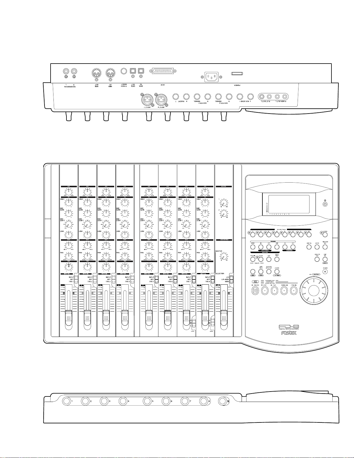
2. CONTROLS, INDICATORS & CONNECTORS
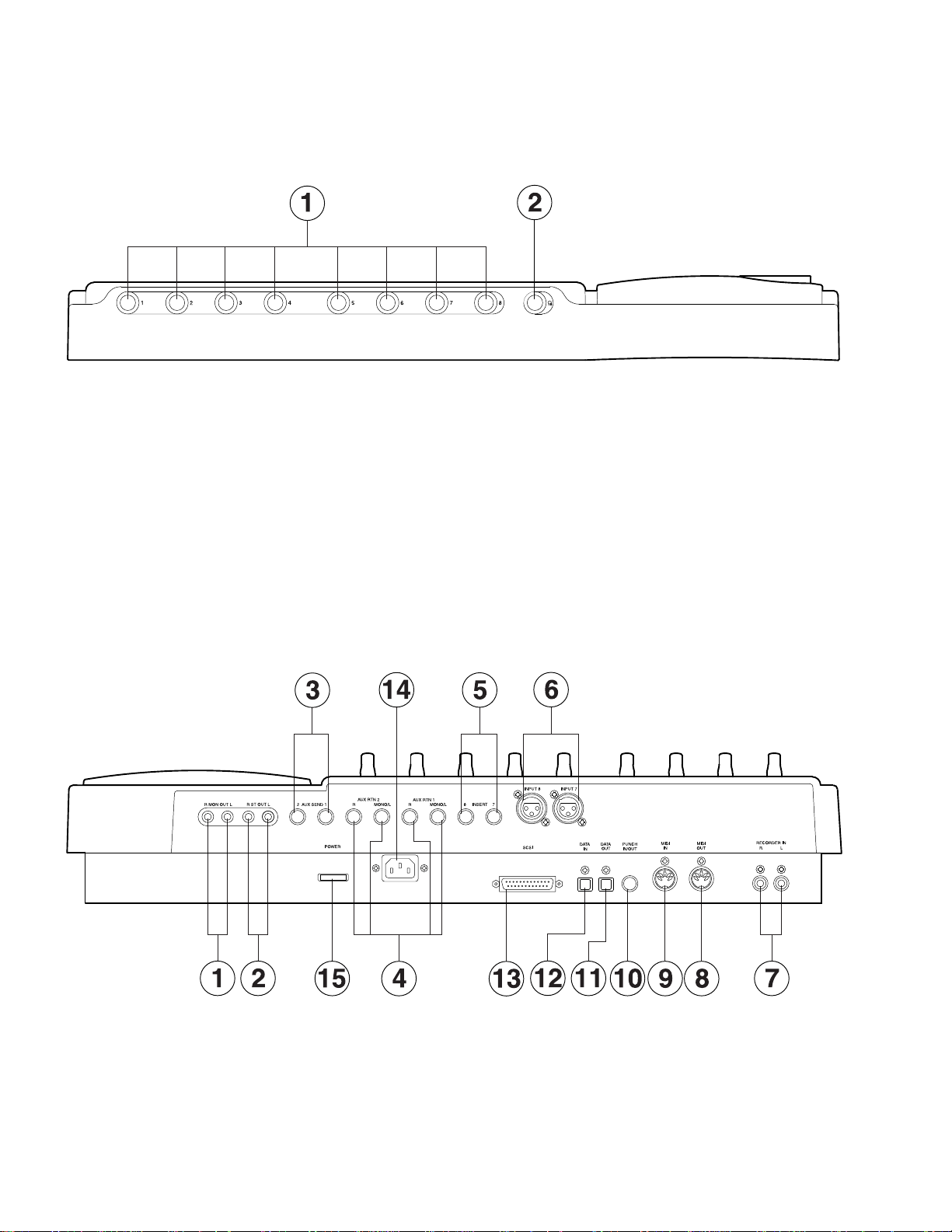
Rear Panel
Control Panel
FD-8
0
PAN
1
Front Panel
7
Page 8
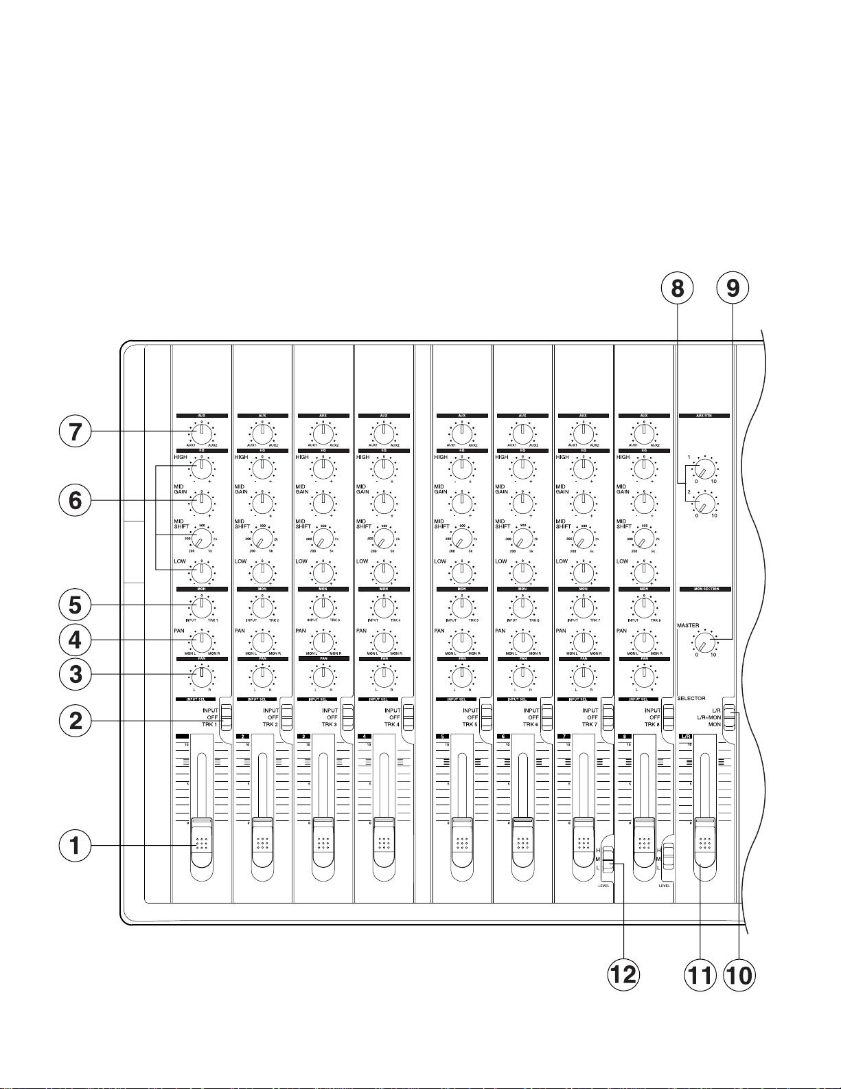
FD-8
Control Panel (Mixer Section)
1. Input faders [
2. Input select switches
[
INPUT SEL (INPUT/OFF/TRK)
3. Panpot knobs [
4. Monitor panpot knobs [
5. Monitor level control knob [
6. Equalizer control knobs
[
EQ (HIGH/MID GAIN & SHIFT/LOW)
]
1-8
PAN (L/R)
]
]
PAN (MON L/MON R)
MON (INPUT/TRK)
]
7. AUX send knobs [
8. AUX return knobs [
AUX (AUX 1/AUX 2)
AUX RTN (1, 2)
]
]
9. Monitor master knob
[
MONITOR SECTION (MASTER)
]
10. Monitor select switch
]
[
SELECTOR (L/R, L/R+MON, MON)
11. Master fader [
12. Input level switches [
]
L/R
LEVEL (H/M/L)
0
]
]
]
1
8
Page 9
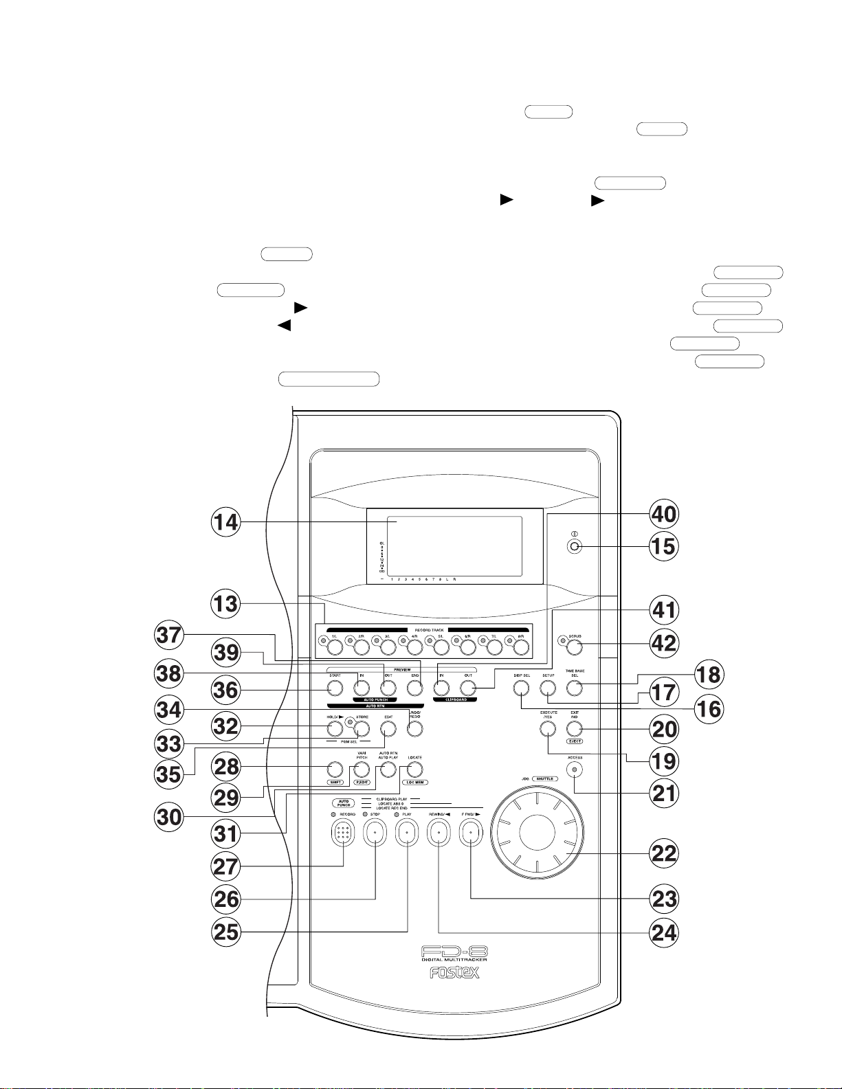
Control Panel (Recorder Section)
13. Record track select keys [
2/R, 3/L, 4/R, 5/L, 6/R, 7/L, 8/R)
14. LCD
15. Contrast adjustment knob
16. Display indication select key [
17. Setup key [
18. Time Base select key [
19. Execute/Yes key [
20. Exit/No key [
21. Access LED [
22. JOG dial [
23. Fast forward button [
24. Rewind button [
25. Play button [
26. Stop button [
27. Record button [
SETUP
EXECUTE/YES
EXIT/NO/ EJECT
ACCESS
JOG/ SHUTTLE
REWIND/
PLAY
STOP
RECORD/ AUTO PUNCH
RECORD TRACK (1/L,
]
DISP SEL
]
TIME BASE SEL
]
]
]
]
F FWD/
]
]
]
]
FD-8
28. Shift key [
29. Vari Pitch key [
30. Auto Return/Auto Play mode on/off key
[
AUTO RTN/AUTO PLAY
]
]
]
31. Locate key [
32. Hold/ key [
33. Store key [
34. Undo/Redo key [
35. Edit key [
36. Auto Return Start key [
37. Auto Return End key [
38. Auto Punch In key [
39. Auto Punch Out key [
40. Clipboard In key [
41. Clipboard Out key [
42. Scrub key [
SHIFT
STORE
EDIT
SCRUB
]
VARI PITCH/ P.EDIT
]
LOCATE/ LOC MEM
HOLD/
UNDO/REDO
]
]
]
]
AUTO RTN START/ PREVIEW
AUTO RTN END/ PREVIEW
AUTO PUNCH IN/ PREVIEW
AUTO PUNCH OUT/ PREVIEW
CLIPBOARD IN/ PREVIEW
CLIPBOARD OUT/ PREVIEW
]
]
]
]
]
]
]
]
]
9
Page 10
FD-8
Front Panel
1. Input jacks [
2. Headphone jack [
1, 2, 3, 4, 5, 6, 7, 8
PHONES
] (
Rear Panel
1. Monitor Out jacks [
2. Stereo Out jacks [
3. AUX Send jacks 1, 2 [
4. AUX Return jacks 1, 2 [
5. Insert jacks 7, 8 [
6. Balanced input connectors 7, 8 [
(
Balanced XLR
7. Recorder in jacks L, R [
(
RCA pin
)
MON OUT L, R
ST. OUT L, R
AUX SEND 1, 2
AUX RTN 1, 2
INSERT 7, 8
)
RECORDER IN L, R
] (
Phone
TRS Phone
] (
RCA pin
] (
RCA pin
] (
] (
] (
TRS Phone
INPUT 7, 8
)
)
)
Phone
Phone
)
]
]
)
)
)
8. MIDI OUT jack [
9. MIDI IN jack [
10. Punch in/out jack [
11. Data output jack [
12. Data input jack [
13. SCSI connector [
14. AC IN connector
15. Power switch [
MIDI IN
DATA IN
POWER
MIDI OUT
PUNCH IN/OUT
DATA OUT
SCSI
] (
DIN 5-pin
] (
DIN 5-pin
] (
] (
OPTICAL
] (
D-SUB 25-pin
]
)
] (
Phone
OPTICAL
)
)
)
)
)
10
Page 11
3. SOFTWARE UPDATE
Same as the FD-4, the FD-8 software can be updated through the SCSI port. This means that unscrewing and opening up the
FD-8 top panel is not necessary to change the EPROMs. Please refer to the following explanation for correct software
updating procedures.
3-1. Method of Sending Software from Fostex Japan
There are two ways of sending the FD-8 updated software.
1.
Updated software in a removable medium (e.g. floppy disk, zip disk, etc.) to be sent via airmail
2.
Updated software as an attachment file to be sent via E-mail
3-2. Required Tools
The following tools/equipment are required to update the FD-8 software.
1.
IBM PC/AT compatible computer with SCSI board
2.
Removable type SCSI drive
3.
Cable between the removable type SCSI drive and the SCSI board
4.
Cable between the removable type SCSI drive and the FD-8 (D-SUB 25-pin)
FD-8
3-3. Software Updating Procedures
Presuming that the updated software is correctly sent and is copied into your computer.
Connect the removable type SCSI drive to the IBM PC/AT compatible computer SCSI port.
1.
Insert the diskette to the removable type SCSI drive and format it by the computer on which Windows 95/98 is running.
2.
Copy the updated software file to the removable type SCSI drive (diskette).
3.
Set the removable type SCSI drive ID to 0 ~ 5 and connect to the FD-8 SCSI port.
4.
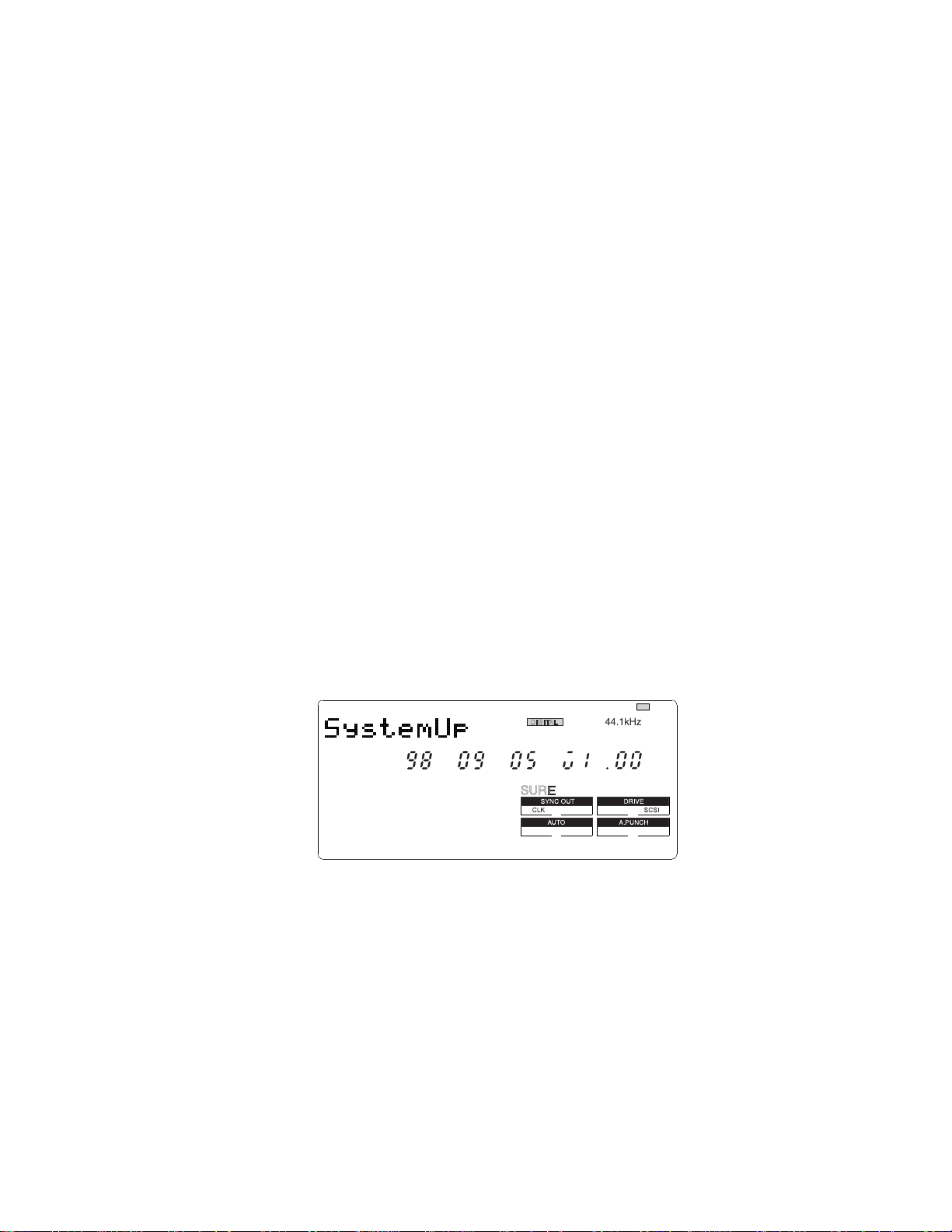
Insert the diskette with updated software file. The FD-8 LCD display shows “No Disk”, “Initial..”, “name of drive (e.g.
5.
ZIP 100)” and “FD8MOT” in order and comes to a standstill at the display below. Memorize the displayed ROM version
and date before updating the software.
: blinking
?
Pressing the EXECUTE/YES key would start updating the software. The display shows “Loading!”, “Writing!” and
6.
“Initial..” in order and automatically returns to the above condition again. Check the displayed ROM version and date if
the software is correctly updated by comparing to the ones displayed in the above procedure 7.
7.
Eject the diskette with updated software file by the press of STOP or EXIT/NO key and insert the diskette formatted by
the FD-8.
8.
Confirm the software version by the Service Mode. For details, please refer to the section “4-2. Flash ROM/CPU version”.
CAUTION:
The diskette in which the updated software file is copied must be formatted by IBM PC/AT computer, not by Macintosh.
1.
If something wrong happens while updating the software (e.g. A blackout occurred while updating the software.), the
2.
FD-8 might not be able to boot up the system software inside the Flash ROM. In such a case, please refer to the section
“4-8. Flash ROM” (page 17).
The SCSI ID to be connected to the FD-8 must be selected to 0 ~ 5. The SCSI ID “6” is used for backing up purpose
3.
exclusively. The SCSI ID “7” cannot be used by technical reasons.
11
Page 12
FD-8
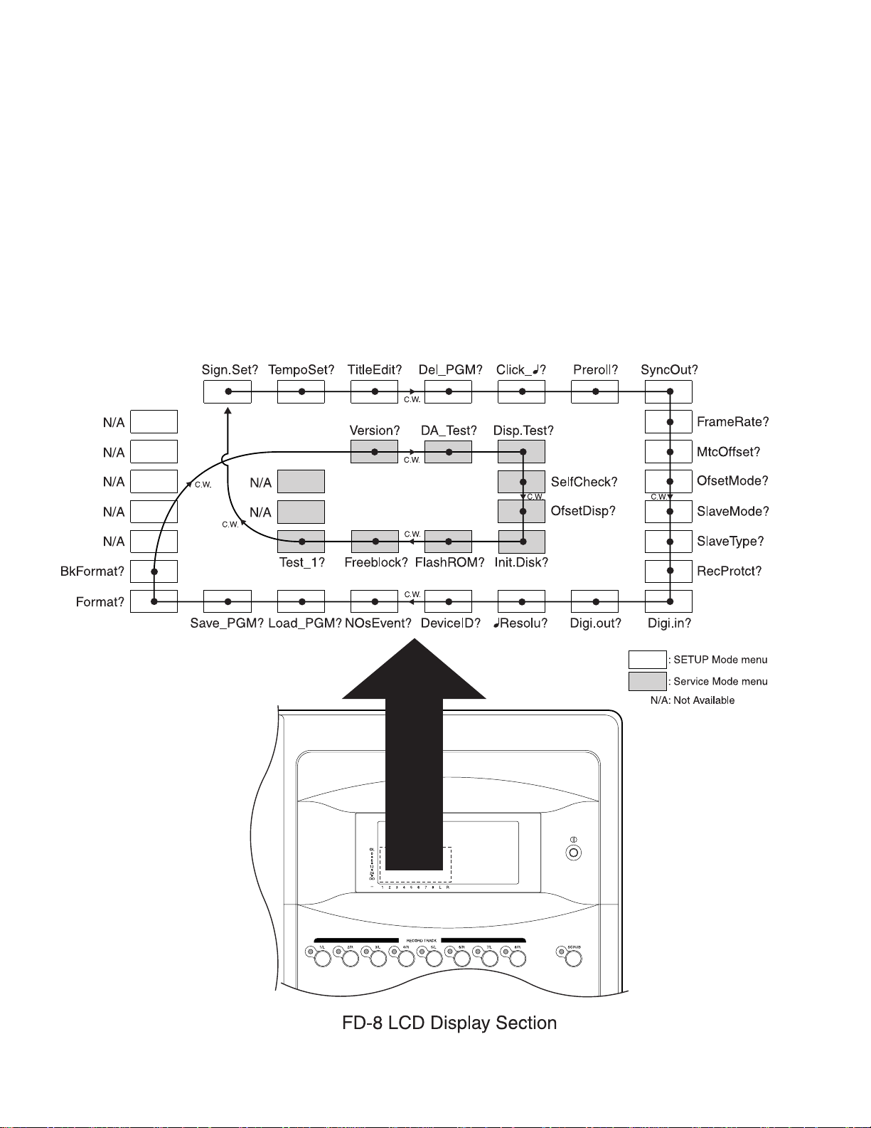
4. SERVICE MODE
There are various optional modes available in the FD-8 Service Mode. Please utilize them when servicing the unit.
4-1. Putting FD-8 into Service Mode
The way of putting the FD-8 into Service Mode is as follow.
1)
Connect a SCSI device, insert the diskette formatted by the FD-8 and turn the power of SCSI device on.
2)
After confirming that the access LED on the SCSI device is lit and then goes out, turn on the power of FD-8.
3)
While holding down the STOP button and SHIFT key, press the SETUP key.
As shown below, by rotating the jog dial C.W. or C.C.W., various optional modes will be displayed in addition to the
general SETUP menus. In order to select a certain optional mode, press the EXECUTE/YES key while its menu is
displayed.
12
Page 13
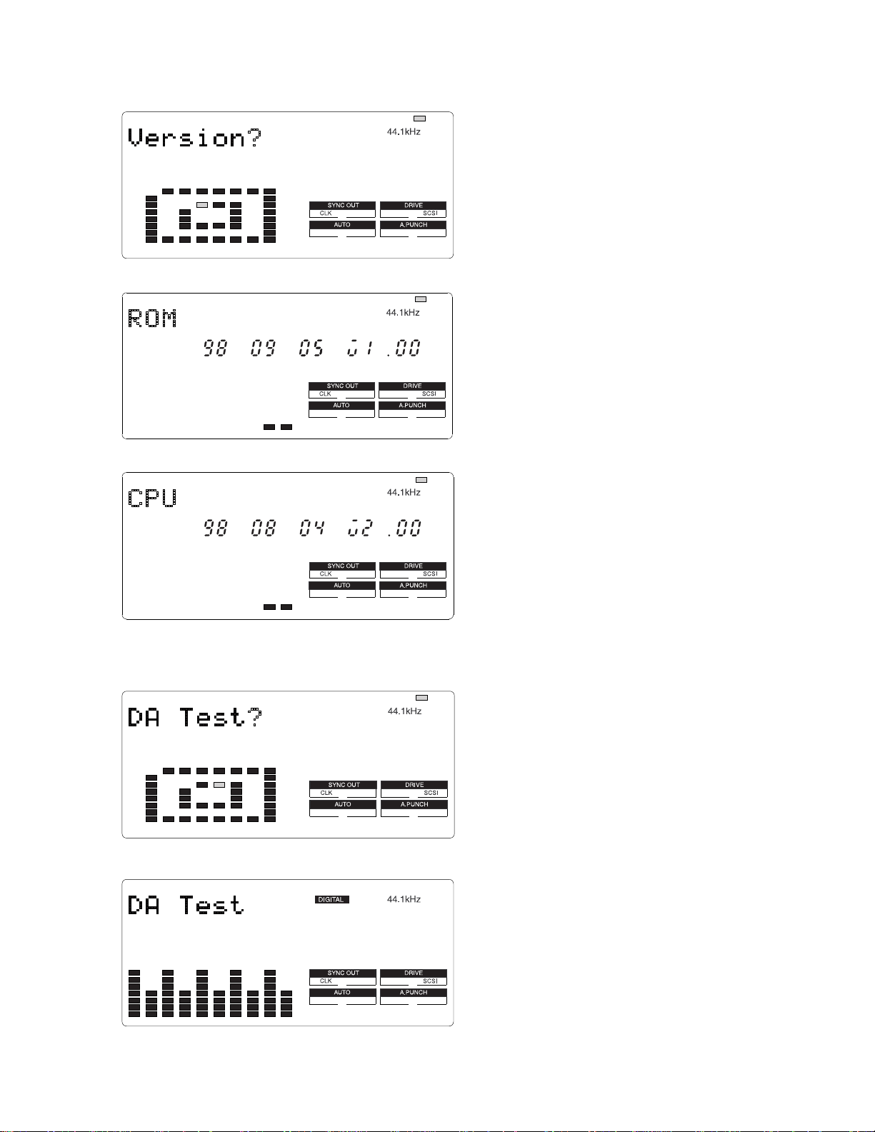
4-2. Flash ROM & CPU version
: blinking
FD-8
This mode is used to check the Flash ROM and CPU versions
currently installed in the unit.
In order to check the version number, press the “EXECUTE/
YES” key while “?” is blinking as shown in the left.
4-3. DA Test
: blinking
: blinking
: blinking
The example on the left indicates that the Flash ROM version
is V1.00 and its programming date is September 5, 1998.
In this condition, by turning the jog dial C.W. or C.C. W.,
the CPU version can be checked.
The example on the left indicates that the CPU version is
V2.00 and its programming date is August 4, 1998.
This mode tests the signal flow from the DATA INPUT jack
to the D/A converter. A S/P DIF digital signal (Fs: 44.1kHz)
must be input to the DATA INPUT jack to execute this test.
Then, press the EXECUTE/YES key while “?” is blinking.
If the FD-8 is in a normal condition, “44.1kHz” and
“DIGITAL” will be lit solid. The odd (1, 3, 5, 7 and L) and
even (2, 4, 6, 8 and R) channels indicate the left and right
input level of S/P DIF digital signal fed to the DATA INPUT
jack respectively.
If the FD-8 is not in a normal condition, “DIGITAL” will
blink and the bargraph meter will not indicate any level.
13
Page 14
FD-8
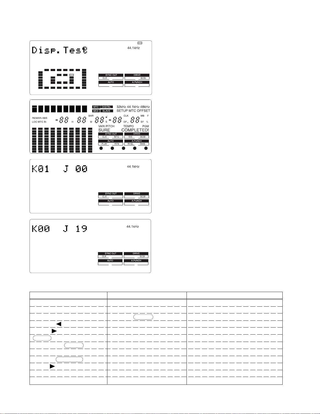
4-4. Display/Button Test
: blinking
This mode tests if all the segments on the LCD display, LEDs
and buttons (switches) on the FD-8 top panel are correctly
working or not.
To execute this test, press the EXECUTE/YES key while
“?” is blinking.
If the FD-8 is in a normal condition, all the segments on the
LCD display will be lit solid and all the LEDs on the top
panel will start blinking.
?
If the FD-8 is not in a normal condition, faulty segments on
the LCD display and/or LEDs on the top panel will remain
unlit.
In this condition, if the EXECUTE/YES key is pressed one
more time, the Button Test can be executed.
The Button Test checks if each key/button and jog dial are
working properly or not. The display on the left indicates
that the RECORD button is pressed and held down. (“K”
stands for the Key and “J” the Jog dial.)
The display on the left indicates the condition when the jog
dial is turned C.W.
The table below shows the relationship between the key/
button/jog dial and the corresponding numbers appear on
the LCD display.
In order to quit the Button Test, turn the jog dial C.W. or
C.C.W. further after “J_20” or “J-19” is displayed
respectively.
14
Key/Button/Jog Dial No.
RECORD K01
STOP K02
PLAY K03
REWIND/ K04
F FWD/ K05
SHIFT K06
VARI PITCH/ P.EDIT K07
AUTO RTN/PLAY K08
LOCATE/ LOC MEM K09
HOLD/ K10
STORE K11
EDIT K12
Key/Button/Jog Dial No.
UNDO/REDO K13
EXECUTE/YES K14
EXIT/NO/ EJECT K15
AUTO RTN START K16
AUTO PUNCH IN K17
AUTO PUNCH OUT K18
AUTO RTN END K19
CLIPBOARD IN K20
CLIPBOARD OUT K21
DISP SEL K22
SETUP K23
TIME BASE SEL K24
Key/Button/Jog Dial No.
RECORD TRACK 1/L K25
RECORD TRACK 2/R K26
RECORD TRACK 3/L K27
RECORD TRACK 4/R K28
RECORD TRACK 5/L K29
RECORD TRACK 6/R K30
RECORD TRACK 7/L K31
RECORD TRACK 8/R K32
SCRUB K34
JOG DIAL (C.W.) J 00 ~ 20
JOG DIAL (C.C.W.) J -00 ~ -19
Page 15
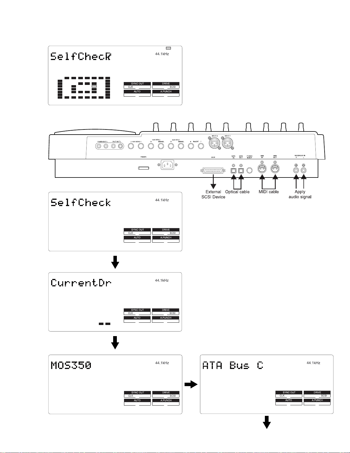
4-5. Self Check
<Cable Connection in “Self Check” Mode>
: blinking
This mode automatically tests the following points in order.
• SCSI bus
• ATA (E-IDE) bus
• MIDI in/out circuit
• S/P DIF digital signal (44.1kHz)
• Vari-pitch circuit
• A/D and D/A circuit (Input Monitor)
FD-8
CAUTION:
In order not to form a MIDI signal loop,
connect the MIDI cable after putting the FD8 into the Service Mode.
To start the Self Check mode, press the EXECUTE/YES
key when “?” is blinking.
As shown in the left, “SelfCheck”, “CurrentDr”, name of
connected SCSI drive (The example on the left shows that
the Magneto Optical drive MOS350 is connected to the FD8 SCSI port.) and “ATA Bus C (check)” appear on the FD8 LCD display in order.
If a 2.5" internal E-IDE hard disk drive is not installed in
the FD-8, the Self Check mode comes to a standstill at “ATA
Bus C (check)” test.
In order to continue the Self Check mode, press the
EXECUTE/YES key again.
Continue to next page
15
Page 16
FD-8
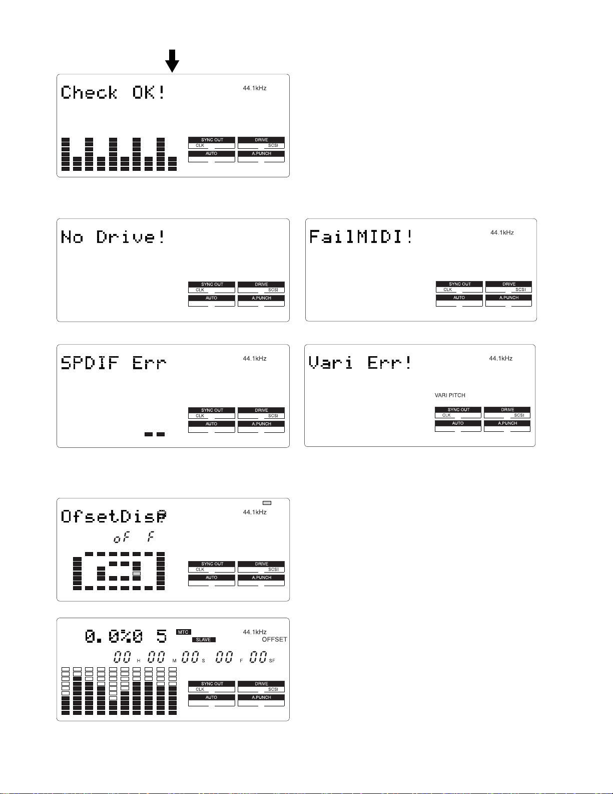
From previous page
If the FD-8 is in a good condition, “Check OK!” will be
displayed and the FD-8 is automatically put into Input
Monitor mode with all the RECORD TRACK LEDs and
RECORD LED flashing. In this condition, if a signal is
applied to the FD-8 RECORDER IN (L, R) jacks, its level
can be monitored on the bargraph level meter.
To quit the Self Check mode, press the EXIT/NO key when
“Check OK!” is displayed.
The followings are examples of error message when the FD-8 is not working properly.
• SCSI function • MIDI function
• Digital Signal in/out (Fs: 44.1kHz)
4-6. Offset Display
• Vari-pitch function
: blinking
This mode determines if the offset value against a master
machine should be displayed or not when the FD-8 is
working as a slave machine.
If you would like to turn ON the offset display, press the
EXECUTE/YES key while “?” is blinking. (The default
setting is “off”.) Then, turn the jog dial C.W. to change the
display to “ON” and press the EXECUTE/YES key.
In order to display the offset value, select the “MTC” time
base and the “REMAINING TIME” as DISP SEL key.
16
CAUTION:
There might be a case that the percentage display does
1.
not indicate “0.0%” exactly. This is caused by the
difference of internal clock between master and slave
machines, which is running independently.
The two-digit numbers displayed in the right of percentage
2.
display (“05” in the left example) is only for software
programming purpose.
Page 17
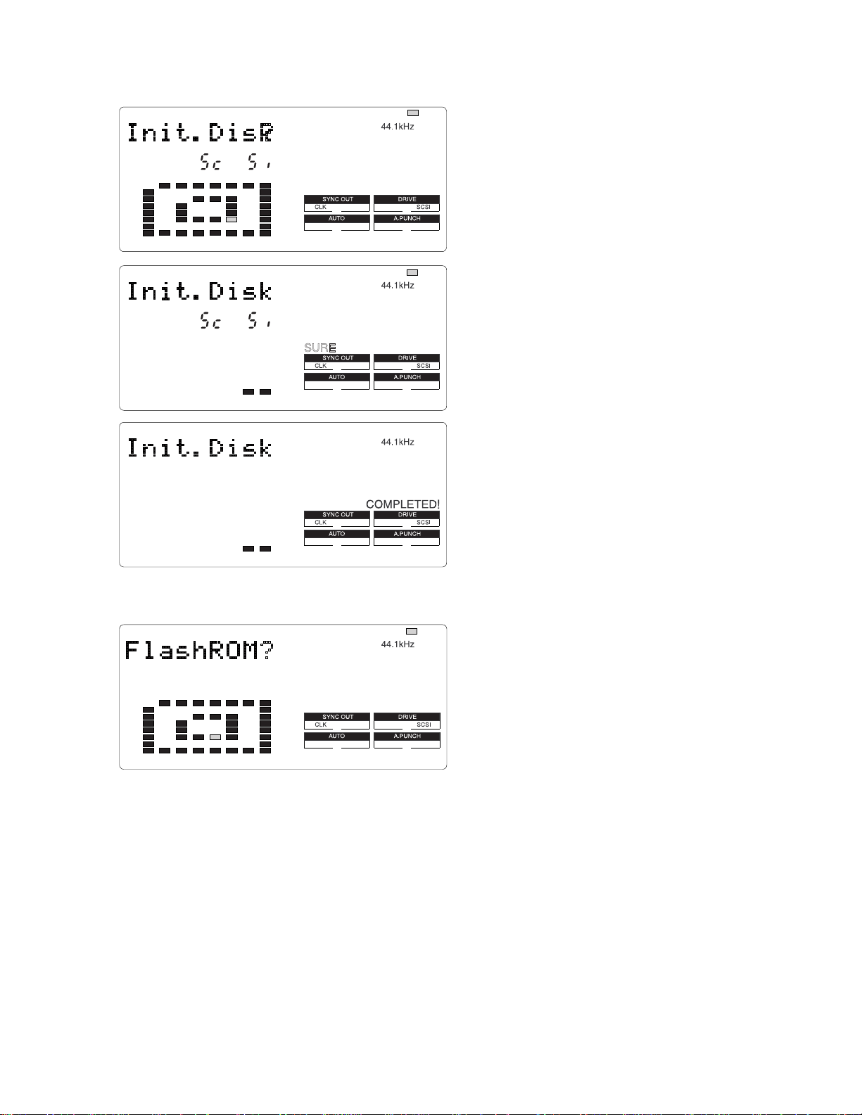
4-7. Initializing Disk
FD-8
: blinking
This mode initializes an external SCSI device connected to
the SCSI port or a 2.5" E-IDE hard disk drive internally
installed. The disk drive currently connected can be
initialized.
CAUTION:
1.
If both the external SCSI drive and the internal 2.5” EIDE hard disk drive are connected at the same time, the
: blinking
SCSI drive is given priority over the 2.5” E-IDE hard
disk drive and is recognized by the FD-8.
2.
Up to 2 x SCSI drives can be connected to the FD-8. One
is for recording / reproducing (SCSI ID: 0 ~ 5) and the
?
other for exclusive backing up (SCSI ID: 6). Initializing
is possible on the SCSI drive (ID: 0 ~ 5) used for recording
/ reproducing only.
After pressing the EXECUTE/YES key, “SURE?” will start
blinking in the LCD display. In this condition, pressing the
EXECUTE/YES key one more time would initialize the
recognized disk drive.
This mode puts the disk back to the condition originally
formatted.
4-8. Flash ROM
: blinking
In this case, the following procedures must be taken.
1.
Turn the switch S1 on the MAIN PCB assy to “EPROM” side.
2.
Mount and solder the EPROM sockets to “U31” and “U32” on the MAIN PCB assy.
3.
Plug the EPROMs into the sockets.
4.
Turn on the power of FD-8.
In this condition, the FD-8 is booted up using the system software inside the EPROMs. The next procedures to take are as
follows.
1.
Put the FD-8 into the Service Mode, select “FlashROM” and press EXECUTE/YES key. (“SURE?” is blinking.)
2.
Press the EXECUTE/YES key one more time to copy the system software from EPROMs to Flash ROM.
3.
Turn the switch S1 to “FLMEM” side.
4.
In order to confirm that the FD-8 is booted up using the system software inside the Flash ROM, turn off the power,
disconnect the EPROMs and turn the power back on again.
5.
After the confirmation, update the system software inside the Flash ROM through SCSI port again.
This mode is used when copying the system software from
EPROMs to Flash ROM.
As mentioned in the section “SOFTWARE UPDATE”, the
FD-8 software inside the Flash ROM can be updated through
the SCSI port. However, if something wrong happens when
updating the software (e.g. A blackout occurred while
updating the software.), the FD-8 might not be able to boot
up by the system software inside the Flash ROM.
17
Page 18
FD-8
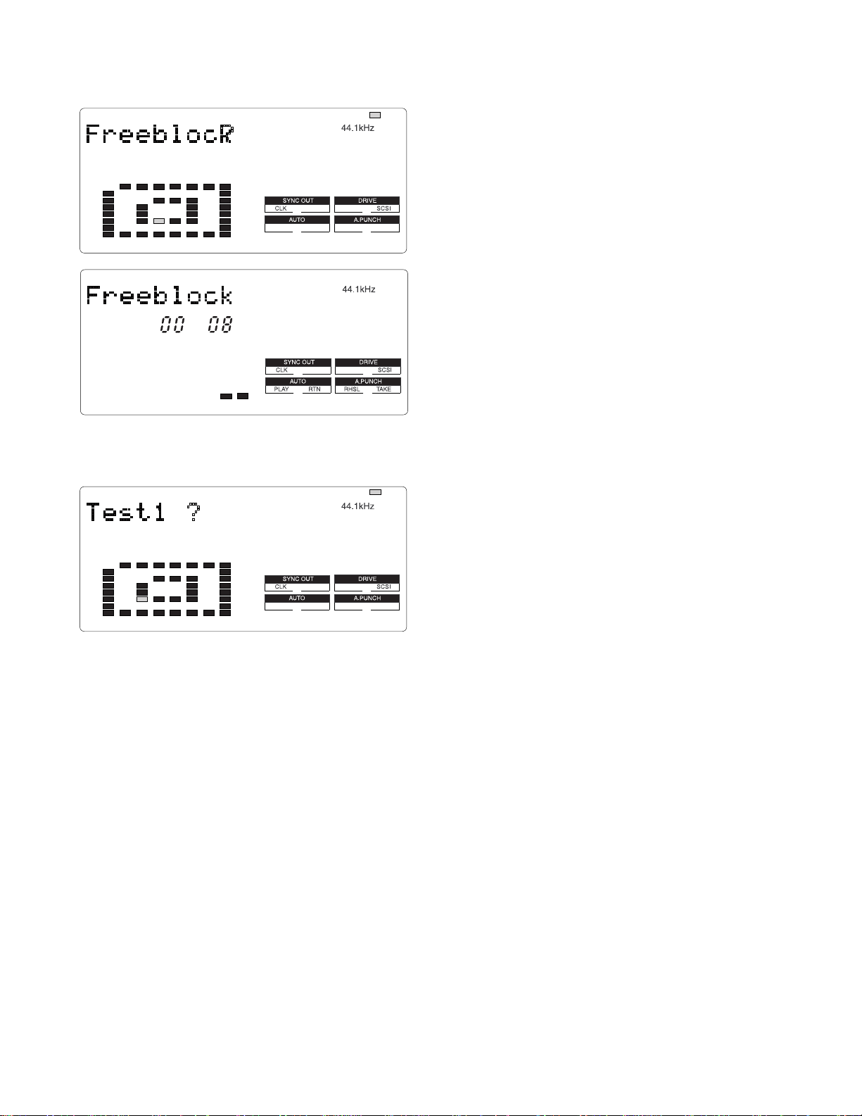
4-10. Free Block Check
: blinking
This mode is used to check the condition of the diskette
inserted into an external SCSI drive connected to the FD-8
or the internal E-IDE hard disk drive. (As mentioned before,
the SCSI drive has a priority unless the SCSI ID is set to
“6”.)
If the Free Block indicates a large number even after
formatting and no signal is recorded or recorded signals are
frequently skipped, the diskette / hard disk drive can be
judged to be in a bad condition.
4-11. Test 1
: blinking
This Service Mode is exclusively designed for software
programming purpose. There is nothing to do with servicing
/ repairing the FD-8.
18
Page 19

5. ERROR CODE LIST
The chart below indicates the error code number and corresponding description. Since the error code list is basically
designed for our engineers to improve the software, the description is quite technical. If you find the FD-8 with one of the
error codes displayed, we encourage you to update the software first. In case updating the software does not solve the
problem, we would like you to inform us about details.
FD-8 ERROR CODE LIST
ERROR
CODE
1 The FD-8 tries to access the address which does not exist.
3 SCSI drive does not boot up correctly when in SCSI access operation.
9
10
11 Link_pointer indicates larger address (out of region) than Link_File address region in RAM.
12 “Pointer_addre” calculation of Link_Pointer is not correct.
14
15
16 “Pointer_addre” calculation of Link_Pointer during recording/reproducing is not correct.
20 src_cash_load: Improper access of link address occurred while PASTE editing.
21 bak_cash_load: Program link during PASTE/MOVE editing is incorrect.
22 bak_cash_load: Imcompatibility problem occurred on program link during PASTE/MOVE editing.
30 Error when executing MOVE editing. Improper Link Pointer. Error in “bak_cash_load” function.
31 Error when executing MOVE editing. Improper Link Pointer. Error in “bak_cash_load” function.
32 Error when executing MOVE editing. Improper Link Pointer. Error in “bak_cash_load” function.
35 Backup_Save:Error occurred when saving data to SCSI device.
36 Backup_Load: Error occurred when loading data from SCSI device.
38 Displayed in Test Mode only. SCSI device cannot be recognized during initial test.
40 dis_cah_load: Improper access occurred when recording/reproducing.
41 dis_cah_load: Improper access occurred when recording/reproducing.
42 dis_cah_load: Improper access occurred when recording/reproducing.
45 get_non_des_block: Remaining disk capacity is insufficient.
52 non_des_cash_save_sub: Improper access occurred when recording/reproducing.
60 remake_free_block: There was improper access to program management region.
61 remake_free_block: There was improper access to program management region.
62 remake_free_block: Number of manageable events exceeds limit.
63 remake_free_block: There was improper access to program management region.
64 remake_free_block: There is an overlapping section in program management region.
96 There was improper access to program management region.
97 There was improper access to program management region when saving System File.
99 There was improper access when fading in/out.
When saving system region sector, its address is registered in Free_block File during Free block File
checking procedure.
Link_pointer which links Audio File indicates smaller address (out of region) than Link_File address region
in RAM.
Link_Pointer during recording/reproducing indicates smaller address (out of region) than actual Link_File
address region.
Link_Pointer during recording/reproducing indicates larger address (out of region) than actual Link_File
address region.
DESCRIPTION
FD-8
19
Page 20
FD-8
6. INSTALLING 2.5" INTERNAL HARD DISK DRIVE
The Model 9045 and a 2.5" E-IDE hard disk drive installing procedures are explained below.
Model 9045 Contents
• Bracket, HD, FD-4/8 (P/N: 8221234000) x 2
• Connector, PI, header, 50P, P2.0, A3E-50PA (P/N: 8245314000) x 1
• Cable, flat, 2P, L150 (P/N: 8276292015) x 1
• Cable assy, flat, 50P, P1.0, L180 (P/N: 8277465018) x 1
• 8 x screws (P 3 x 5 CZn)
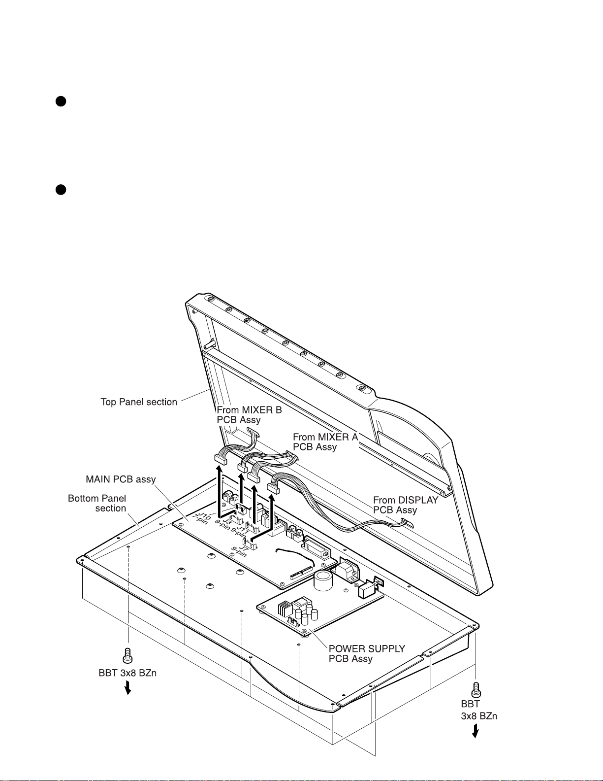
Installing Procedures
Loosen 17 x screws (BBT 3 x 8 BZn) fixing the FD-8 Top Panel section to the Bottom Panel section.
1)
Remove the following cables from the connectors on the MAIN PCB assy.
2)
• 7-pin cable to the J10 (from MIXER A PCB assy)
• 9-pin cable to the J11 (from MIXER A PCB assy)
• 9-pin cable to the J3 (from MIXER B PCB assy)
• 9-pin cable to the J7 (from DISPLAY PCB assy)
20
Page 21

FD-8
NOTE:
3)
4)
Not like the FD-4 MAIN PCB assy, the E-IDE 50-pin connector J12 and 2-pin cable between W1 and W5 have
already been mounted and soldered. So, it is not necessary to remove the FD-8 MAIN PCB assy when installing
a 2.5” E-IDE hard disk drive.
Using 4 x screws (P 3 x 5 CZn), fix the HD Bracket to a 2.5" E-IDE hard disk drive.
Using 4 x screws (P 3 x 5 CZn), fix the 2.5" E-IDE hard disk drive/HD bracket to the Bottom Panel section.
(During the above procedures 6) and 7), adjust the tightening position of screws to the HDD and to the bottom panel
so that screws are not bothered from each other.)
21
Page 22

FD-8
Connect the 50-pin flat cable between J12 of MAIN PCB assy and the HDD connectors. In order to connect pins
8)
straight, twist the cable as shown below. (Pin-1 of J12 (RED) must go to Pin-1 (RED) of HDD connectors.)
Connect the following cables from the connectors on the MAIN PCB assy.
9)
• 7-pin cable to the J10 (from MIXER A PCB assy)
• 9-pin cable to the J11 (from MIXER A PCB assy)
• 9-pin cable to the J3 (from MIXER B PCB assy)
• 9-pin cable to the J7 (from DISPLAY PCB assy)
Tighten 17 x screws (BBT 3 x 8 BZn) fixing the FD-8 Top Panel section to the Bottom Panel section.
10)
22
Page 23

7. EXPLODED VIEW, PCB ASSEMBLY AND PARTS LIST
FD-8 OVERALL EXPLODED VIEW
Ref. No. Part No. Description
1 8212 6501 00 Window, LCD, FD-8
2 8212 6490 00 Panel, top, FD-8
3 8221 2581 00 Panel, bottom, FD-8
4 8274 1240 00 PCB assy, XLR, FD-4/8
5 8216 6841 00 Shield, mixer, FD-8
6 8226 2370 00 Button assy, control, FD-4/8
7 8274 1260 00 PCB assy, Mixer B, FD-8
8 8226 2230 01 Knob, volume, C
9 8274 1560 00 PCB assy, Display, FD-8
10 8274 1570 00 PCB assy, Main, FD-8
11 8274 1580 00 PCB assy, Power, FD-8
Ref. No. Part No. Description
12 8204 0820 00 Plate, mounting, B
13 8221 2571 00 Bracket, jack, FD-8
14 8274 1230 00 PCB assy, Jack, FD-4/8
15 8226 2380 00 Knob, jog, FD-4/8
16 8216 6670 00 Sheet, jog, FD-4/8
17 8226 1601 03 Knob, slide, N4.5
18 8226 2390 01 Knob, fader, N4.5
19 8207 0117 01 Holder, cord, CS-1
20 8207 0120 00 Foot, FF-822
21 8276 8010 00 Cord, power, UL/CSA, VM0033-0089,
USA/CND
8276 8021 00 Cord, power, CEE, 0309B-0310B, EUR
8276 8000 00 Cord, power, VM1292-1298, DM
22 8221 2610 00 Bracket, AC-IN, FD-8
23 8226 0130 04 Button, push, B, N08
24 8216 6860 00 Sheet, isolation, power, FD-8
25 8216 6361 01 Cushion, button, FD-4/8
26 8274 1220 00 PCB assy, Mixer A, FD-4/8
27 8216 6361 00 Cushion, battery, PD-4/FD-8
28 8276 3750 09 Cable assy, earth lug, D3, L90
29 8277 3530 20 Cable assy, earth lug, D3-D3, #20, L200
30 8277 3530 15 Cable assy, earth lug, D3-D3, #20, L150
31 8239 0007 08 Fuse, 20, TDLY, 0.8A, 250V
32 8242 2340 13 Filter, EMI, ferrite, core,
HF70RH16x28x10
33 8212 2700 00 Shield, power, FD-8
FD-8
23
Page 24

24
FD-8
FD-8 PCB PATTERN DRAWING
• Parts Side of MAIN PCB assy
4
C906
3
C156
2
1
J101
C101
5
2115
U101
C103 C203
C102
C151
C152
U151
AK5351
C157
13
C99
1
J201 J9
RCH INLCH IN
L101
L201
C201
5
2115
U201
1
C154
R152
R91
R92
1
C202
C153
1
C155
C166
13
S1
U31
C162
1
C167
FLMEMEPROM
7
R909
C904
C113
C111
C114
C161
U152
AK4321
TO MIXER
J10
1
L7
TO MIXER 1-4CH
L14
L13
L11
1
J3 J11
R908
L102
L202
L302
L402
L103
L203
C116
1
13
U153
C163
C164
C216
4565
C266
17
C316
C213
1
4565
5
C211
U253
C311
C214
C261
C263
C264
C262 C262 C262
13
U252
AK4321
1
C267
R45
R67
C366
C98
1
L19
99
L303
L403
C416
C313
5
C511
C314
C411
C361
U352
AK4321
1
C367
8251521 100 PCB MAIN FD-8
AB C
L20 L17 L18
1
L502
L602
L702
L802
L503
C516
C616
1
C363
13
U32
C413
4565
U353
5
C711
C414
C611
C461
C364 C464
U452
AK4321
1
C467
C466
L603
C716
1
C463
13
L703
U453
17
4565
TO MIXER
5-8CH
L803
C816
5
C811
8
C91
TP6
TEST
L1
U902
C6
D7
U901
C913
D6
1
U452
HC04
R87
U30
25 48
C100
C76
L21
C905
R49
1
124
J8
U1
C3
C4
U27 U25U26U28
J7
TO DISPLAY
29
56
J4
OUT
1
C18
U11
4
C7
C2
C1
C10
C13
W3
POWER
TO
18
U22 U20U21
U23
9
C79
28
U15
SH7040
57
X3
C71
C8
TP5
MNI
LOCK VARI
C63
L6
C61
U2
1
112
85
84
R71
J5
IN
C26
C60
C68
U10
C66
C15
U16
RESET
R48
C96
R72
R73
R78
C19
TP4
U33
C72
9
1
L4
C49
L3
W1
TO HDD
1
C92
TP2
C62
TC9246
1
U9
U14
L2
U17
4
22
C29
R12
C28
TP1
LOCK PLL
C59
C21
C50
U9
TC9246
C57
1
X2
R7
109
144
136
C912
21
22
42
43 63
J6
9
W2
C46
X4
X1
73108
U5
GA2
12
1
U3
ADAC
DE FG
D1
75
72
37
84
64
14
C47
U8
BH9595FP
1
50 26
U7
MB86604L
76 100
C30
21
22
U4
ADAC
42
43 63
H
C48
4
2551
1
R96
R27
W8
W7
W6
12
W5
49
3
R8
R9
R28
R96
R95
2
250
1
1
84
J12
1
64
Page 25

• Foil Side of MAIN PCB assy
J5 J4
C33
C26
R41
TP2
R36
1
8
R37
C65
R39
C17
5
U24
HC32
R40
R36
4
U13
21035
L4
R42
1
C72
C41
C91
R19
R25
C42
R97
R24
C86
C58
C39
C43
R23
C44
J6
D1
C46
C25
R22
C55
C45
X4
C34
R21
25
13
C48
1
2
C38
R20
R26
C80
C82
C81
R29
C40
C87
W5
50
4939291991
C37
403020102
C83
C51
C54
R1
C56
C22
R98
R34
C36
HCU04
1
C31
R2
TP1
C910
C24
R5
C53
R32
U6
R4R6R3
R31
14
1
C59
C52
C67
R17
R18
R30
L3
C35
8
R15
R14
C32
TP4
R13
C27
C23
C21
C84
C85
C14
R10
C73
R70
1
R11
C64R35
C9
L2
C70
R16
R69
R68
C94
C93
C63
TP5
C20
L6
R77
C909
1
C12
D5
C11
R46
U12
HC14
14
13
10
9118
12
J11 J3
9191
R813
R812
R912
R902
C812
R906
R901
C6
C913
R904
R903
R814
R811
C91
C816
C811
R714
C815
C465
C715
C463
C612
C716
R713
R711
R612
R712
C711
R80
R43
C3
R79
R64
R74
R83
R79
R63
R907
U903
1
R62
R66
TP6
L1
C5
R905
D4 D3
J8
U11
C7
C10
C13
9
C88
C77
8
C69
X3
R47
R76
R75
R50
U14
8
J1
R35
C1
R84
R85
R86
1
R81
R82
J7
R44
R65
C95
C78
R52
R51
C74
C75
R613
C712
C461
R461
R614
R611
3
C616
C611
R466
76
5
R514
C516
C615
C515
C363
C365
2
C412
R513
R511
R413
R412
C512
R512
C511
C361
4
R361
1
R414
R411
C411
R366
C416
C415
J10
1
J9
R213
R212
C212
R314
C265
R214
C312
R312
C311
C261
1
R88
R261
HC157
1717
R211
C211
R266
U29
C216
C215
R114
C115
C165
9
C316
R313
C315
R311
C263
C97
11
7
C163
C116
R111
C904
R112
R113
3
C112
C111
C161
R161
S1
1
C903
J201
1
2
C208
R204
W201
R201
R205
R166
1
U31U32
3
C201
R203
C153
R206
R111
R209
C207
R202
J101
1
J6
2
R101
C108
R104
R105
1
C101
C151
3
W101
R103
R109
R106
C156
C107
R102
R151
25
FD-8
Page 26

26
• MIXER A, JACK and XLR PCB assys
C703
S801
L6
R513
R613
R703
R803
W3
R503
C530
R603
C532
R809
C804
R160
C511
R514
C611
R709
C805
C803
L/MONO
C503
C603
R614
C705
C806
C146
R153
J35
C706
C141
R151
U301
U302
R710
R515
R615
U401
C807
C142
C531
C533
R810
R150
AUX RTN 1
C512
C612
C707
C731
C730
R813
U1
C144
R164
C166
C165
R165
L2
C504
C604
R713
R814
C145
INSERT3/7
1
6
R801
C801
R167
R168
C9
J39
W12
C167
C501
R501
R166
R701
C601
R601
C701
R802
C802
L5
C702
R702
INSERT4/8
R266
J40
PCB MIXA
8251967 201
J501
R502
C510
J601
R602
C610
J701
R705
R707
S701
R708
R706
J801
R807
R808
R806
J1
R267
R268
C267
R805
C502
C602
R704
R804
R253
R260
C704
C246
R504
R604
R714
R152
R163
C264
FD-8
L
LR
J31
OUT
L3
J37
L/MONO
9
J36
R
J21
R540
AUX RTN 2 R
J11 TO MIXER
AGND
1
MON L
MON R
STEREO R
STEREO L
J38
1
5
J33
AUX
SEND1
R5
Q5
R11
R512
R12
R545
J34
AUX
SEND2
Q6
R6
W2
1
MUTE8
MUTE7
MUTE6
MUTE5
REPRO8
REPRO7
REPRO6
REPRO5
L4
R546
R640
U510
S502
R528
R526
R527
R612
R525
R535
R645
R533
R534
R532
R646
U610
R740
R628
S602
C708
R626
R627
R712
R625
R635
R745
R633
R634
R632
R746
C710
C733
C711
U402
C811
C810
C143
C241
C4
C242
R250
C245
R252
C3
R251
C244
U2
R263
C164
U6
R264
C265
R715
R815
R265
C712
C812
C732
C266
R840
C243
R10
R811
R711
C808
C240
C140
U710
U810
R161
C809
S702
S802
R728
C260
R261
R726
R733
R734
R828
R826
R727
R827
R735
R725
R812
R835
R825
R845
R732
R846
R833
R832
R834
R11
C163
S1
C263
C160
C161
C261
R2
C8
C7
STEREO
R7
R1
Q1
1
J10
9
AGND
R548
C518
R523
R648
C618
C619
R8
TO MIXER
C517
C519
R522
C617
R2
Q2
8
J22
C514
C520
C614
R622
R9
PCB JACK
8251967 202
1
3
AGND
AUX2
AUX1
R519
R544
C521
R619
R644
C621
R623
C6
R157
R723
R823
C152
C718
C818
R824
R155
C717
C719
R724
C817
C819
C620
C714
R719
R744
C721
R722
C720
C814
R819
R844
C821
R822
C820
R255
C252
C151
U3
U4
R256
C153
C254
R257
C5
C155
C162
C262
R748
R848
C709
R162
U5
R156
R262
C154
R1
R
J32
OUT
MONITOR
Q4
R3
Q3
R10
J23
3
AGND
A-12
R542
C534
C535
R642
C634
C635
R742
C734
C735 C715
R842
C834
C835
R258
C251
R173
R172
C255
R272
R158
R4
A+12
R273
C513
C613
C713
C813
R518
C515
R618
C615
R718
R818
J1
3/7/L
1
L2
TO MIXER
R541
L1
1
J3
REC R
REC L
MUTE
A-12
W1
R543
U503
R516
R517
C516
R520
R641
R521
R537
R536
C522
R530
R529
R630
R643
R629
U603
R616
R617
C616
R741
R620
C622
R621
R637
R636
R743
U703
R820
R716
R717
C716
R720
R841
R821
R721
R737
R736
R729
C722
R830
R843
R829
C822
U803
R816
C815
C816
R817
R837
R836
R13
J2
4/8/R
L4
L3
6
PCB XLR
8251967 203
H GND
AGND
A+12
17
C1
R547
C2
R531
R647
R631
R747
R730
R831
C250
R731
C150
R847
9
AGND
IN8 RTN
IN8 SEND
IN7 RTN
W11
W10
IN7 SEND
AUX 2R
AUX 2L
AUX 1R
C171
AUX 1L
1
1
R12
C170
C270
R270
C253
C273
R271
C271
R171
C173
C272
C172
R170
8
Page 27

• MIXER B PCB assy
C102
R102
C101
R101
C110
C202
R202
C201
R201
C210
C302
R302
C301
R301
C310
C402
R402
C401
R401
J401J301J201J101
8251516 000
PCB MIXB
C410
R114
R214
R314
R414
R113
R313
R313
R413
R103
C130
R203
R303
R403
C230
C330
C430
C103
C111
C203
C211
C303
C311
C411
C403
U101
U201
R215
U301
R315
U401
R415
C131
C231
C212
C331
C312
R115
C431
C412
C112
C204
C304
C404
C104
R204
R304
R404
R104
R340R240R140 R440
R112
U110
R212
U210
R312
U310
R412
U410
S102
S202
S302
S402
R127
R227
R327
R427
R125
R225
R325
R425
R128
R145
R228
R345
R328
R345
R428
R445
1
R126
R226
R326
R426
W3
91
R135
R132
R134
R234
R334
R434
W21
5
R232
R332
R432
R133
R146
R235
R233
R346
R335
R333
R346
R435
R433
R446
R323R223
R423
R123
R148
R248
R348
R448
C117
C217
C317
C417
C119
C219
C319
C419
R122
R222
R422R322
C118
C218
C318
C418
C116
C216
C316
C416
R117
R116
R320
R420
1220
R217
R216
R220
R317
R316
R417
R416
R321
R421
1221
R221
R137
R136
R143
R237
R236
R243
R337
R336
R343
R437
R436
R443
C122
C222
C322
C422
R129
R229
R329
R429
R130
R131
R230
R231
R330
R331
R430
R431
R147
R247
R347
R447
R142
R242
R342
R442
3
C135
C235
C335
C435
W23
R118
R218
R318
R418
C115
U102
R141
C113
C215
U202
R241
C213
C315
U302
R341
C313
C415
U402
R441
C413
1
C120
C234
C221
R144
R119
C113
C220
C234
C221
R244
R219
C213
C320
C334
C321
R344
R319
C413
C420
C434
C421
R444
R419
C414
W22
1
3
27
FD-8
Page 28

28
• DISPLAY PCB assy
C19
R10
U5
R11
R12
R13
C14
R9
R14
R15
FD-8
TO MAIN
R41
C9
R37
W1
1
R42
R7
R6
5
REW
PLAY
GREEN
STOP
GREEN
REC
1
3
4
C10
C11
FF
S28
C8
S32
D32
S31
D31
S30
D30
S29
D29
R4
R5
R22
R19
X1
R8
C7
R34
R36
R35
R33
D51
R32
D50
R31
RED
D49
F
R20
R21
C16
E
U6
C15
R18
R17
D
D28
C
B
A
1
R39
R40
GREEN
9
D53
C1
C2
R2
R1 ACCESS
C4
C6
U2
C12
Q1
Q2
VARI
S36
S27
RTN/PL
AUTO
LOCATE
S26
D25
S25
SHIFT
R3
R38
R26
D36
R25
D27
R24
D26
R23
2
R16
R43
R
RED
D56
L
RED
D55
RED
D48
RED
D47
(R)
RED
D46
U4
(L)
RED
D45
RED
D44
41
6
8251518 100
PCB DISPLAY FD-4/8
RED
D43
RED
D42
RED
D41
5
D16
S16
D15
S15
8/R7/L
D8
S8
D7
S7
6/R
D6
S6
5/L
D5
S5
4/R
D4
S4
3/L
D3
S3
2/R
D2
S2
1/L
S1
TIME
D34
S34
D35
SETUP
S35
D33
S33
DISP SEL
OUT
S14
D14
IN
S13
END
S12
D12
OUT
S11
IN
S10
D1
START
S9
4
D13
D11
D10
D9
GREEN
D54
EXIT
S18
EXEC
S17
S24
UNDO/REDO
EDIT
S23
R28
STORE
S22
D22
R27
S21
HOLD
R30
R29
D18
C3
D17
C5
D24
D23
D21
3
4
3
1
5
L1
40
1
L2
7
Page 29

• POWER PCB assy
COUT2
D+5
D+5
DGND
DGND
A+12
AGND
AGND
A–12
L5
R5
R7
4
R6
C8
R8
R4
C7
L2
C16
COUT1
18
J1
C19
C20
C11
C12
R9
C15
U3
U4
1
U2
3
2
U5
6
D4
11
D6
C9
C17
C10
C18
D5
R3
R2
C4
D2
T1
C14
5
1
8251523 000
PCB POWER FD-8
C3
CS
U1
D3
C5C5
C2
CSB
C24
D
IPD
DSB
RSB
R1
C13
D1
L3
3
4
2
1
F1
C22
C1
1
2
4
3
L1
C21
W1
N
L4
L
S1
T800mA 250V
CAUTION
RISK OF ELECTRIC SHOCK ZONE
J2
29
FD-8
Page 30

FD-8
FD-8 Parts List
• MAIN PCB assy
Ref. No. Part No. Description
8274 1570 00 PCB Assy, Main, FD-8
B001 8251 5211 00 Plain PCB, Main, FD-8
ICs
Ref. No. Part No. Description
U001, 002 8236 5403 01 ST, analog, regulator,
NJM78M05DLA
U003, 004 8236 0843 00 QFP, digital, gate array, A.D.A.C.
U005 8236 0818 00 QFP, digital, gate array, ASPI
U006 8236 5610 04 ST, digital, 74HCU04
U007 8236 0828 00 QFP, digital, SCSI, M86604L
U008 8236 0829 00 SOP, digital, SCSI, terminate,
BH9595FP-Y
U009, 010 8236 5034 00 ST, digital, VCO, TC9246F
U011 8234 0199 00 Opt., photo coupler, PC900
U012 8236 5600 14 ST, digital, 74HC14
U013 8236 5025 00 ST, analog, reset, NJM2103M
U014 8236 5701 01 ST, digital, driver, DTC114EK
U015 8236 0838 02 QFP, digital, CPU, main, FD-8,
mask, SH7042, F28
U016~019 N/A
U020~023 8236 5704 01 ST, digital, driver, DTA114EK
U024 8236 5600 32 ST, digital, 74HC32
U025~028 8236 5704 01 ST, digital, driver, DTA114EK
U029 8236 5601 57 ST, digital, 74HC157
U030 8236 0840 11 TSOP, digital, Flash ROM,
M29F400T90, SGS
U031, 032 N/A
U033 8236 0831 00 SOJ, digital, DRAM,
HM5118160AJ-7
U034, 035 N/A
U101, 201 8236 5050 11 ST, analog, op amp,
NJM2115M (TEI)
U151 8236 5407 00 ST, digital, AD, AK5351
U152~452 8236 5053 00 ST, digital, DA, AK4320
U153~453 8236 5412 00 ST, analog, NJM4565M
U901, 902 8236 5701 01 ST, digital, driver, DTC114EK
U903 8236 5704 01 ST, digital, driver, DTA114EK
U904 8236 5600 04 ST, digital, 74HC04
DIODEs
Ref. No. Part No. Description
D001 8234 1050 00 VF, SCHOTTKY, EK13
D002 N/A
D003~006 8234 5028 00 ST, DAN202K
D007 8234 7506 00 ST, RB400D
RESISTORs
Ref. No. Part No. Description
R001~007 8230 5001 01 ST, carbon, 1/10W, 100Ω, 5%
R008 8230 5001 03 ST, carbon, 1/10W, 10kΩ, 5%
R009 8230 5005 62 ST, carbon, 1/10W, 5.6kΩ, 5%
Ref. No. Part No. Description
R010 8230 5003 32 ST, carbon, 1/10W, 3.3kΩ, 5%
R011 8230 5002 22 ST, carbon, 1/10W, 2.2kΩ, 5%
R012 8230 5001 01 ST, carbon, 1/10W, 100Ω, 5%
R013 8230 5003 31 ST, carbon, 1/10W, 330Ω, 5%
R014 8230 5001 05 ST, carbon, 1/10W, 1MΩ, 5%
R015 8230 5000 00 ST, carbon, 1/10W, 0Ω, 5%
R016 8230 5003 31 ST, carbon, 1/10W, 330Ω, 5%
R017 8230 5001 05 ST, carbon, 1/10W, 1MΩ, 5%
R018 N/A
R019 8230 5004 72 ST, carbon, 1/10W, 4.7kΩ, 5%
R020 N/A
R021~25 8230 5001 01 ST, carbon, 1/10W, 100Ω, 5%
R026, 027 8230 5000 00 ST, carbon, 1/10W, 0Ω, 5%
R028 N/A
R029 8230 5004 72 ST, carbon, 1/10W, 4.7kΩ, 5%
R030 8230 5001 52 ST, carbon, 1/10W, 1.5kΩ, 5%
R031 8230 5001 01 ST, carbon, 1/10W, 100Ω, 5%
R032 8230 5002 24 ST, carbon, 1/10W, 220kΩ, 5%
R033 N/A
R034 8230 5003 31 ST, carbon, 1/10W, 330Ω, 5%
R035 8230 5007 51 ST, carbon, 1/10W, 750Ω, 5%
R036 8230 5008 22 ST, carbon, 1/10W, 8.2kΩ, 5%
R037 N/A
R038 8230 5003 31 ST, carbon, 1/10W, 330Ω, 5%
R039 8230 5001 03 ST, carbon, 1/10W, 10kΩ, 5%
R040 8230 5001 01 ST, carbon, 1/10W, 100Ω, 5%
R041 8230 5005 61 ST, carbon, 1/10W, 560Ω, 5%
R042 8230 5002 23 ST, carbon, 1/10W, 22kΩ, 5%
R043, 044 8230 5001 01 ST, carbon, 1/10W, 100Ω, 5%
R045~048 8230 5001 03 ST, carbon, 1/10W, 10kΩ, 5%
R049 8230 5003 31 ST, carbon, 1/10W, 330Ω, 5%
R050 8230 5001 02 ST, carbon, 1/10W, 1kΩ, 5%
R051 8230 5001 03 ST, carbon, 1/10W, 10kΩ, 5%
R052 8230 5001 01 ST, carbon, 1/10W, 100Ω, 5%
R053, 054 N/A
R061 N/A
R062~065 8230 5001 01 ST, carbon, 1/10W, 100Ω, 5%
R066 8230 5001 52 ST, carbon, 1/10W, 1.5kΩ, 5%
R067 N/A
R068 8230 5003 31 ST, carbon, 1/10W, 330Ω, 5%
R069 8230 5002 22 ST, carbon, 1/10W, 2.2kΩ, 5%
R070 8230 5003 31 ST, carbon, 1/10W, 330Ω, 5%
R071 8230 5001 03 ST, carbon, 1/10W, 10kΩ, 5%
R072 N/A
R073 8230 5000 00 ST, carbon, 1/10W, 0Ω, 5%
R074~076 8230 5002 21 ST, carbon, 1/10W, 220Ω, 5%
R077 8230 5001 03 ST, carbon, 1/10W, 10kΩ, 5%
R078 8230 5001 01 ST, carbon, 1/10W, 100Ω, 5%
R079~087 8230 5001 03 ST, carbon, 1/10W, 10kΩ, 5%
R088~090 N/A
R091 8230 5001 03 ST, carbon, 1/10W, 10kΩ, 5%
R092~094 N/A
R095, 096 8230 5001 02 ST, carbon, 1/10W, 1kΩ, 5%
30
Page 31

FD-8
Ref. No. Part No. Description
R097 8230 5001 05 ST, carbon, 1/10W, 1MΩ, 5%
R098 8230 5001 01 ST, carbon, 1/10W, 100Ω, 5%
R099 N/A
R151 8230 5001 00 ST, carbon, 1/10W, 10Ω, 5%
R152 8230 5001 01 ST, carbon, 1/10W, 100Ω, 5%
R101, 201 8230 5002 03 ST, carbon, 1/10W, 20kΩ, 5%
R102, 202 8230 5001 23 ST, carbon, 1/10W, 12kΩ, 5%
R103, 203 8230 5001 03 ST, carbon, 1/10W, 10kΩ, 5%
R104, 204 8230 5001 03 ST, carbon, 1/10W, 10kΩ, 5%
R105, 205 8230 5003 31 ST, carbon, 1/10W, 330Ω, 5%
R106, 206 8230 5003 31 ST, carbon, 1/10W, 330Ω, 5%
R107, 207 N/A
R108, 208 N/A
R109, 209 8230 5001 04 ST, carbon, 1/10W, 100kΩ, 5%
R111~811 8230 5001 03 ST, carbon, 1/10W, 10kΩ, 5%
R112~812 8230 5001 03 ST, carbon, 1/10W, 10kΩ, 5%
R113~813 8230 5002 72 ST, carbon, 1/10W, 2.7kΩ, 5%
R114~814 8230 5001 04 ST, carbon, 1/10W, 100kΩ, 5%
R161~461 8230 5001 00 ST, carbon, 1/10W, 10Ω, 5%
R901 N/A
R902 8230 5001 01 ST, carbon, 1/10W, 100Ω, 5%
R903 8230 5002 21 ST, carbon, 1/10W, 220Ω, 5%
R904, 905 8230 5001 01 ST, carbon, 1/10W, 100Ω, 5%
R906, 907 8230 5001 03 ST, carbon, 1/10W, 10kΩ, 5%
R908, 909 8230 5001 02 ST, carbon, 1/10W, 1kΩ, 5%
R910, 911 N/A
R912 8230 5001 03 ST, carbon, 1/10W, 10kΩ, 5%
R913 N/A
CAPACITORs
ALU = Electrolytic type
CER = Ceramic type
Ref. No. Part No. Description
C001 N/A
C002 8233 5021 04 ST, CER, 50V, 0.1µF, +80-20%, CC20F
C003 8232 1431 06 VT, ALU, 16V, 10µF, 20%, SME-VB
C004 8233 5021 04 ST, CER, 50V, 0.1µF, +80-20%, CC20F
C005~007 N/A
C008 8233 5021 04 ST, CER, 50V, 0.1µF, +80-20%, CC20F
C009, 010 8232 1431 06 VT, ALU, 16V, 10µF, 20%, SME-VB
C011 8233 5021 04 ST, CER, 50V, 0.1µF, +80-20%, CC20F
C012, 013 N/A
C014 8232 1431 06 VT, ALU, 16V, 10µF, 20%, SME-VB
C015 8233 5021 04 ST, CER, 50V, 0.1µF, +80-20%, CC20F
C016, 017 N/A
C018 8233 5021 04 ST, CER, 50V, 0.1µF, +80-20%, CC20F
C019, 020 8233 5041 03 ST, CER, 25V, 0.01µF, 10%, CC20R
C021 8232 1431 06 VT, ALU, 16V, 10µF, 20%, SME-VB
C022~025 8233 5041 03 ST, CER, 25V, 0.01µF, 10%, CC20R
C026 8232 1431 06 VT, ALU, 16V, 10µF, 20%, SME-VB
C027 8233 5004 71 ST, CER, 50V, 470pF, 5%, CC20SL
C028 8233 5001 01 ST, CER, 50V, 100pF, 5%, CC20SL
C029 N/A
Ref. No. Part No. Description
C030 8233 5004 71 ST, CER, 50V, 470pF, 5%, CC20SL
C031, 032 8233 5002 20 ST, CER, 50V, 22pF, 5%, CC20SL
C033, 034 8233 5041 03 ST, CER, 25V, 0.01µF, 10%, CC20R
C035, 036 N/A
C037~040 8233 5041 03 ST, CER, 25V, 0.01µF, 10%, CC20R
C041~045 N/A
C046 8232 1431 06 VT, ALU, 16V, 10µF, 20%, SME-VB
C047 8233 5021 04 ST, CER, 50V, 0.1µF, +80-20%, CC20F
C048 8232 1431 06 VT, ALU, 16V, 10µF, 20%, SME-VB
C049~051 8233 5041 03 ST, CER, 25V, 0.01µF, 10%, CC20R
C052 8233 5001 50 ST, CER, 50V, 15pF, 5%, CC20SL
C053~057 8233 5041 03 ST, CER, 25V, 0.01µF, 10%, CC20R
C058 8233 5094 74 ST, CER, 25V, 0.47µF, 20%, KC30E
C059 8232 1431 06 VT, ALU, 16V, 10µF, 20%, SME-VB
C060 8233 5021 04 ST, CER, 50V, 0.1µF, +80-20%, CC20F
C061, 062 8233 5041 03 ST, CER, 25V, 0.01µF, 10%, CC20R
C063 8232 1431 06 VT, ALU, 16V, 10µF, 20%, SME-VB
C064 8233 5001 50 ST, CER, 50V, 15pF, 5%, CC20SL
C065 8233 5094 74 ST, CER, 25V, 0.47µF, 20%, KC30F
C066, 067 8233 5041 03 ST, CER, 25V, 0.01µF, 10%, CC20R
C068~070 8233 5021 04 ST, CER, 50V, 0.1µF, +80-20%, CC20F
C071 8233 5041 03 ST, CER, 25V, 0.01µF, 10%, CC20R
C072 8232 1461 05 VT, ALU, 50V, 1µF, 20%, SME-VB
C073 8233 5041 03 ST, CER, 25V, 0.01µF, 10%, CC20R
C074, 075 8233 5003 30 ST, CER, 50V, 33pF, 5%, CC20SL
C076 8233 5041 03 ST, CER, 25V, 0.01µF, 10%, CC20R
C077 8233 5001 01 ST, CER, 50V, 100pF, 5%, CC20SL
C078 8233 5004 71 ST, CER, 50V, 470pF, 5%, CC20SL
C079 N/A
C080~083 8233 5041 03 ST, CER, 25V, 0.01µF, 10%, CC20R
C084~087 N/A
C088 8233 5021 04 ST, CER, 50V, 0.1µF, +80-20%, CC20F
C089, 090 N/A
C091 8232 1431 06 VT, ALU, 16V, 10µF, 20%, SME-VB
C092 N/A
C093, 094 8233 5041 03 ST, CER, 25V, 0.01µF, 10%, CC20R
C095 8233 5001 01 ST, CER, 50V, 100pF, 5%, CC20SL
C096~097 8233 5041 03 ST, CER, 25V, 0.01µF, 10%, CC20R
C098, 099 N/A
C100 8233 5041 03 ST, CER, 25V, 0.01µF, 10%, CC20R
C101, 201 8232 1431 06 VT, ALU, 16V, 10µF, 20%, SME-VB
C102, 202 8233 5001 52 ST, CER, 50V, 0.0015µF, 5%, CC20R
C103, 203 8233 5041 03 ST, CER, 25V, 0.01µF, 10%, CC20R
C104, 204 8233 5041 03 ST, CER, 25V, 0.01µF, 10%, CC20R
C105, 205 N/A
C106, 206 N/A
C107, 207 N/A
C108, 208 N/A
C111~811 8232 1431 06 VT, ALU, 16V, 10µF, 20%, SME-VB
C112~812 8233 5006 81 ST, CER, 50V, 680pF, 5%, CC20SL
C113~413 8233 5041 03 ST, CER, 25V, 0.01µF, 10%, CC20R
C114~414 8233 5041 03 ST, CER, 25V, 0.01µF, 10%, CC20R
C115~815 N/A
31
Page 32

FD-8
Ref. No. Part No. Description
C116~816 8232 1434 76 VT, ALU, 16V, 47µF, 20%, SME-VB
C151 N/A
C152 8233 5041 03 ST, CER, 25V, 0.01µF, 10%, CC20R
C153 8232 1431 06 VT, ALU, 16V, 10µF, 20%, SME-VB
C154 8233 5041 03 ST, CER, 25V, 0.01µF, 10%, CC20R
C155 8233 5021 04 ST, CER, 50V, 0.1µF, +80-20%, CC20F
C156 8232 1431 06 VT, ALU, 16V, 10µF, 20%, SME-VB
C157 8233 5041 03 ST, CER, 25V, 0.01µF, 10%, CC20R
C158, 159 N/A
C161~461 N/A
C162~462 8233 5041 03 ST, CER, 25V, 0.01µF, 10%, CC20R
C163~463 8232 1434 76 VT, ALU, 16V, 47µF, 20%, SME-VB
C164~464 8233 5041 03 ST, CER, 25V, 0.01µF, 10%, CC20R
C165~465 N/A
C166~466 8232 1431 06 VT, ALU, 16V, 10µF, 20%, SME-VB
C167~467 8233 5041 03 ST, CER, 25V, 0.01µF, 10%, CC20R
C901, 902 N/A
C903 8233 5041 03 ST, CER, 25V, 0.01µF, 10%, CC20R
C904 8232 1431 06 VT, ALU, 16V, 10µF, 20%, SME-VB
C905 8233 5041 03 ST, CER, 25V, 0.01µF, 10%, CC20R
C906 8233 5021 04 ST, CER, 50V, 0.1µF, +80-20%, CC20F
C907, 908 N/A
C909 8233 5041 03 ST, CER, 25V, 0.01µF, 10%, CC20R
C910 N/A
C911 8230 5000 00 Resistor, ST, carbon, 1/10W, 0Ω, 5%
C912 8233 5003 30 ST, CER, 50V, 33pF, 5%, CC20SL
C913 8232 1441 07 VT, ALU, 25V, 100µF, 20%,
SME-VB
MISCELLANEOUS
Ref. No. Part No. Description
E1401 N/A
E1402 N/A
J001, 002 N/A
J003 8245 1714 09 Connector, PI, jack, 8283, 9P, YEL
J004 8245 5520 00 Connector, opt., GPIF32T
J005 8245 5530 00 Connector, opt., GPIF32R
J006 8245 3120 05 Connector, PL, jack, D-SUB, 25P,
70057-025, EMIFIL
J007 8245 1711 09 Connector, PI, jack, 8283, 9P, WHT
J008 8245 2980 00 Connector, PL, jack, phone,
LGR4609-7000
J009 8245 4200 00 Connector, jack, DIN5P,
YKF51-5053
J010 8245 1711 07 Connector, PI, jack, 8283, 7P, WHT
J011 8245 1711 09 Connector, PI, jack, 8283, 9P, WHT
J012 8245 3140 00 Connector, PI, header, 50P,
PITCH2.0
J101, 201 8245 2850 00 Connector, PL, jack, RCA, 1P,
YKB11-0923, W/S
L001~003 8276 9130 00 Wire, jumper, isolation, 1/4 type
L004 8242 1962 23 Coil, PVT, 22µH, LF5.0S
L005 N/A
L006 8242 1962 23 Coil, PVT, 22µH, LF5.0S
L007 8242 5011 21 Filter, ST, EMI, 120, 25%,
MMZ2012S
Ref. No. Part No. Description
L008~010 N/A
L011 8242 5011 21 Filter, ST, EMI, 120, 25%,
MMZ2012S
L012 N/A
L013, 014 8242 5011 21 Filter, ST, EMI, 120, 25%,
MMZ2012S
L015, 016 N/A
L017~021 8242 5011 21 Filter, ST, EMI, 120, 25%,
MMZ2012S
L022 N/A
L101, 201 8242 5011 21 Filter, ST, EMI, 120, 25%,
MMZ2012S
L102~802 8242 5011 21 Filter, ST, EMI, 120, 25%,
MMZ2012S
L103~803 8242 5011 21 Filter, ST, EMI, 120, 25%,
MMZ2012S
S001 N/A
X001 8256 1700 01 Resonator, ST, XTL, 22.579MHZ,
FUP-FBB3AFUJICOM
X002 N/A
X003 8256 1790 01 Resonator, PT, CER, 7.000MHz,
F5, EFOEN
X004 N/A
Y3301 82165950 00 Shield, RCA
Y3302 82166680 00 Shield, phone, FD-4/8
W001, 002 N/A
W003 8276 7320 30 Cable assy, 8P, 8263WHT-5395,
#22, L300
W004 N/A
W005 8276 2920 15 Cable, flat, 2P, L150
W006~008 N/A
W101, 201 N/A
W102~402 N/A
• MIXER A PCB assy
Ref. No. Part No. Description
8274 1220 00 PCB Assy, Mixer A, FD-4/8
B001 8251 9672 01 Plain PCB, Mixer A, FD-4/8
ICs
Ref. No. Part No. Description
U001, 002 8236 0366 00 SIP, analog, NJM2068LD
U003, 004 8236 0342 02 SIP, analog, NJM4558L
U005 8236 0366 00 SIP, analog, NJM2068LD
U006 8236 0352 03 SIP, analog, NJM4556AL
U301 8236 0342 02 SIP, analog, NJM4558L
U401 8236 0366 00 SIP, analog, NJM2068LD
U302, 402 8236 0342 02 SIP, analog, NJM4558L
U503~803 8236 0342 02 SIP, analog, NJM4558L
U510~810 8236 0781 07 PT, digital, driver, DTC143TS
32
Page 33

FD-8
RESISTORs
Ref. No. Part No. Description
R001, 002 8230 1504 79 VT, carbon, 1/2W, 4.7Ω, 5%
R010 8240 2540 00 Pot, PI, SL45, 50kΩAA,
NS-4502GVP, L20
R011~013 8240 2530 00 Pot, PI, RT12, 30kΩAA,
EVJY00, L20
R150, 250 8230 1388 23 HT, carbon, 1/4W, 82k Ω, 5%
R151, 251 8230 1382 03 HT, carbon, 1/4W, 20kΩ, 5%
R152, 252 8230 1384 73 HT, carbon, 1/4W, 47kΩ, 5%
R153, 253 8230 1381 04 HT, carbon, 1/4W, 100kΩ, 5%
R155, 255 8230 1388 23 HT, carbon, 1/4W, 82kΩ, 5%
R156, 256 8230 1381 03 HT, carbon, 1/4W, 10kΩ, 5%
R157, 257 8230 1381 03 HT, carbon, 1/4W, 10kΩ, 5%
R158, 258 8230 1381 03 HT, carbon, 1/4W, 10kΩ, 5%
R160, 260 8230 1388 23 HT, carbon, 1/4W, 82kΩ, 5%
R161, 261 8230 1381 04 HT, carbon, 1/4W, 100kΩ, 5%
R162, 262 8230 1388 23 HT, carbon, 1/4W, 82kΩ, 5%
R163, 263 8230 1382 03 HT, carbon, 1/4W, 20kΩ, 5%
R164, 264 8230 1382 04 HT, carbon, 1/4W, 200kΩ, 5%
R165, 265 8230 1381 03 HT, carbon, 1/4W, 10kΩ, 5%
R166, 266 8230 1381 03 HT, carbon, 1/4W, 10kΩ, 5%
R167, 267 8230 1382 00 HT, carbon, 1/4W, 20Ω, 5%
R168, 268 N/A
R170, 270 8230 1381 01 HT, carbon, 1/4W, 100 Ω, 5%
R171, 271 8230 1381 01 HT, carbon, 1/4W, 100Ω, 5%
R172, 272 8230 1382 73 HT, carbon, 1/4W, 27kΩ, 5%
R173, 273 8230 1382 73 HT, carbon, 1/4W, 27kΩ, 5%
R501, 601 8230 1381 04 HT, carbon, 1/4W, 100kΩ, 5%
R502, 602 8230 1381 01 HT, carbon, 1/4W, 100Ω, 5%
R503, 603 8230 1381 04 HT, carbon, 1/4W, 100kΩ, 5%
R504, 604 8230 1381 01 HT, carbon, 1/4W, 100Ω, 5%
R701, 801 8230 1381 04 HT, carbon, 1/4W, 100kΩ, 5%
R702, 802 8230 1381 04 HT, carbon, 1/4W, 100kΩ, 5%
R703, 803 8230 1382 04 HT, carbon, 1/4W, 200kΩ, 5%
R704, 804 8230 1382 04 HT, carbon, 1/4W, 200kΩ, 5%
R705, 805 8230 1382 03 HT, carbon, 1/4W, 20kΩ, 5%
R706, 806 8230 1382 03 HT, carbon, 1/4W, 20kΩ, 5%
R707, 807 8230 1382 02 HT, carbon, 1/4W, 2kΩ, 5%
R708, 808 8230 1382 02 HT, carbon, 1/4W, 2kΩ, 5%
R709, 809 8230 1382 04 HT, carbon, 1/4W, 200kΩ, 5%
R710, 810 8230 1382 04 HT, carbon, 1/4W, 200kΩ, 5%
R711, 811 8230 1381 01 HT, carbon, 1/4W, 100Ω, 5%
R512~812 8230 1382 02 HT, carbon, 1/4W, 2kΩ, 5%
R513~813 8230 1382 04 HT, carbon, 1/4W, 200kΩ, 5%
R514~814 8230 1389 12 HT, carbon, 1/4W, 9.1kΩ, 5%
R515~815 8230 1381 03 HT, carbon, 1/4W, 10kΩ, 5%
R516~816 8230 1381 03 HT, carbon, 1/4W, 10kΩ, 5%
R517~817 8230 1381 03 HT, carbon, 1/4W, 10kΩ, 5%
R518~818 8230 1382 02 HT, carbon, 1/4W, 2kΩ, 5%
R519~819 8230 1382 02 HT, carbon, 1/4W, 2kΩ, 5%
R520~820 8230 1381 32 HT, carbon, 1/4W, 1.3kΩ, 5%
R521~821 8230 1381 32 HT, carbon, 1/4W, 1.3kΩ, 5%
R522~822 8230 1389 12 HT, carbon, 1/4W, 9.1kΩ, 5%
R523~823 8230 1389 12 HT, carbon, 1/4W, 9.1kΩ, 5%
R524~824 N/A
Ref. No. Part No. Description
R525~825 8230 1382 73 HT, carbon, 1/4W, 27kΩ, 5%
R526~826 8230 1382 73 HT, carbon, 1/4W, 27kΩ, 5%
R527~827 8230 1383 63 HT, carbon, 1/4W, 36kΩ, 5%
R528~828 8230 1383 63 HT, carbon, 1/4W, 36kΩ, 5%
R529~829 8230 1382 73 HT, carbon, 1/4W, 27kΩ, 5%
R530~830 8230 1383 63 HT, carbon, 1/4W, 36kΩ, 5%
R531~831 8230 1383 63 HT, carbon, 1/4W, 36kΩ, 5%
R532~832 8230 1382 73 HT, carbon, 1/4W, 27kΩ, 5%
R533~833 8230 1382 73 HT, carbon, 1/4W, 27kΩ, 5%
R534~834 8230 1383 63 HT, carbon, 1/4W, 36kΩ, 5%
R535~835 8230 1383 63 HT, carbon, 1/4W, 36kΩ, 5%
R536~836 8230 1382 20 HT, carbon, 1/4W, 22Ω, 5%
R537~837 8230 1382 20 HT, carbon, 1/4W, 22Ω, 5%
R540~840 8240 2500 00 Pot., PI, SL45, 50kΩA,
NS-4502VP, L20
R541~841 8240 2680 00 Pot., PI, RT09, 10kΩB, CC,
EVUF3A, L20
R542~842 8240 2700 00 Pot., PI, RT12, 50kΩCC,
EVJY00, L20
R543~843 8240 2510 00 Pot., PI, RT09, 50kΩB, CC,
EVUF3A, L20
R544~844 8240 2510 00 Pot., PI, RT09, 50kΩB, CC,
EVUF3A, L20
R545~845 8240 2510 00 Pot., PI, RT09, 50kΩB, CC,
EVUF3A, L20
R546~846 8240 2510 00 Pot., PI, RT09, 50kΩB, CC,
EVUF3A, L20
R547~847 8240 2490 00 Pot., PI, RT12, 100kΩB, CC CT,
EVJ02J, L20
R548~848 8240 2830 00 Pot., PI, RT12, 20kΩB, CC CT,
EVJ02J, L20
CAPACITORs
ALU = Electrolytic type
CER = Ceramic type
PES = Mylar type
Ref. No. Part No. Description
C001, 002 8232 1431 07 VT, ALU, 16V, 100µF, 20%, SME-VB
C003~006 8232 8181 04 VT, CER, 25V, 0.1µF, 20%, YF
C007, 008 8232 1432 27 VT, ALU, 16V, 220µF, 20%, SME-VB
C009 8232 8181 04 VT, CER, 25V, 0.1µF, 20%, YF
C140, 240 8232 1424 76 VT, ALU, 10V, 47µF, 20%, SME-VB
C141, 241 8232 8011 00 VT, CER, 50V, 10pF, 5%, SL
C142, 242 8232 8011 00 VT, CER, 50V, 10pF, 5%, SL
C143, 243 8232 1431 06 VT, ALU, 16V, 10µF, 20%, SME-VB
C144, 244 8232 8011 00 VT, CER, 50V, 10pF, 5%, SL
C145, 245 8232 8012 20 VT, CER, 50V, 22pF, 5%, SL
C146, 246 8232 1424 76 VT, ALU, 10V, 47µF, 20%, SME-VB
C150, 250 8232 1424 76 VT, ALU, 10V, 47µF, 20%, SME-VB
C151, 251 8232 8011 00 VT, CER, 50V, 10pF, 5%, SL
C152, 252 8232 8011 00 VT, CER, 50V, 10pF, 5%, SL
C153, 253 8232 8011 01 VT, CER, 50V, 100pF, 5%, SL
C154, 254 8232 8011 01 VT, CER, 50V, 100pF, 5%, SL
C155, 255 8232 1431 06 VT, ALU, 16V, 10µF, 20%, SME-VB
C160, 260 8232 1424 76 VT, ALU, 10V, 47µF, 20%, SME-VB
33
Page 34

FD-8
Ref. No. Part No. Description
C161, 261 8232 8011 00 VT, CER, 50V, 10pF, 5%, SL
C162, 262 8232 8011 00 VT, CER, 50V, 10pF, 5%, SL
C163, 263 8232 1424 76 VT, ALU, 10V, 47µF, 20%, SME-VB
C164, 264 8232 8011 00 VT, CER, 50V, 10pF, 5%, SL
C165, 265 8232 8011 00 VT, CER, 50V, 10pF, 5%, SL
C166, 266 8232 1431 06 VT, ALU, 16V, 10µF, 20%, SME-VB
C167, 267 8232 1422 27 VT, ALU, 10V, 220µF, 20%, SME-VB
C170, 270 8232 1424 76 VT, ALU, 10V, 47µF, 20%, SME-VB
C171, 271 8232 1424 76 VT, ALU, 10V, 47µF, 20%, SME-VB
C172, 272 8232 8014 71 VT, CER, 50V, 470pF, 5%, SL
C172, 273 8232 8014 71 VT, CER, 50V, 470pF, 5%, SL
C501, 601 8232 8011 01 VT, CER, 50V, 100pF, 5%, SL
C502, 602 8232 1431 06 VT, ALU, 16V, 10µF, 20%, SME-VB
C503, 603 8232 8011 01 VT, CER, 50V, 100pF, 5%, SL
C504, 604 8232 1424 76 VT, ALU, 10V, 47µF, 20%, SME-VB
C510~810 8232 1424 76 VT, ALU, 10V, 47µF, 20%, SME-VB
C511~811 8232 8011 01 VT, CER, 50V, 100pF, 5%, SL
C512~812 8232 8011 01 VT, CER, 50V, 100pF, 5%, SL
C513~813 8232 9012 23 VT, PES, 50V, 0.022µF, 5%, AMZ
C514~814 8232 9011 03 VT, PES, 50V, 0.01µF, 5%, AMZ
C515~815 8232 8011 01 VT, CER, 50V, 100pF, 5%, SL
C516~816 8232 8011 01 VT, CER, 50V, 100pF, 5%, SL
C517~817 8232 9016 82 VT, PES, 50V, 0.0068µF, 5%, AMZ
C518~818 8232 9016 82 VT, PES, 50V, 0.0068µF, 5%, AMZ
C519~819 8232 9011 53 VT, PES, 50V, 0.015µF, 5%, AMZ
C520~820 8232 8012 20 VT, CER, 50V, 22pF, 5%, SL
C521~821 8232 8012 20 VT, CER, 50V, 22pF, 5%, SL
C522~822 8232 1424 76 VT, ALU, 10V, 47µF, 20%, SME-VB
C530, 730 8232 8181 04 VT, CER, 25V, 0.1µF, +80-20%, YF
C531, 731 8232 8181 04 VT, CER, 25V, 0.1µF, +80-20%, YF
C532, 732 8232 8181 04 VT, CER, 25V, 0.1µF, +80-20%, YF
C533, 733 8232 8181 04 VT, CER, 25V, 0.1µF, +80-20%, YF
C534~834 8232 8181 04 VT, CER, 25V, 0.1µF, +80-20%, YF
C535~835 8232 8181 04 VT, CER, 25V, 0.1µF, +80-20%, YF
C701, 801 8232 8011 01 VT, CER, 50V, 100pF, 5%, SL
C702, 802 8232 8011 01 VT, CER, 50V, 100pF, 5%, SL
C703, 803 8232 1421 07 VT, ALU, 10V, 100µF, 20%, SME-VB
C704, 804 8232 1421 07 VT, ALU, 10V, 100µF, 20%, SME-VB
C705, 805 8232 8011 00 VT, CER, 50V, 10pF, 5%, SL
C706, 806 8232 8011 00 VT, CER, 50V, 10pF, 5%, SL
C707, 807 N/A
C708, 808 8232 1424 76 VT, ALU, 10V, 47µF, 20%, SME-VB
C709, 809 8232 1424 76 VT, ALU, 10V, 47µF, 20%, SME-VB
MISCELLANEOUS
Ref. No. Part No. Description
E601 Wire, jumper, F5
E602 Wire, jumper, F10
E603 Wire, jumper, F15
J001 8245 2980 00 Connector, PL, jack, phone,
LGR4609-7000
J021 8245 1711 05 Connector, PI, jack, 8283, 5P, WHT
J022 8245 1711 03 Connector, PI, jack, 8283, 3P, WHT
J023 8245 1711 03 Connector, PI, jack, 8283, 3P, WHT
Ref. No. Part No. Description
J501~801 8245 2980 00 Connector, PL, jack, phone,
LGR4609-7000
S001 8253 6550 16 Switch, PI, slide, 4-3, non-shortening,
SSSF0, L09
S701, 801 8253 6550 13 Switch, PI, slide, 2-3, non-shortening,
SSSF0, L09
S502~802 8253 6550 13 Switch, PI, slide, 2-3, non-shortening,
SSSF0, L09
W001 8276 7770 20 Cable assy, 7P, WHT MT/F-MT/BS,
L200
W002 8276 7790 30 Cable assy, 9P, WHT MT/F-MT/BS,
L300
W010 8276 7780 20 Cable assy, 8P, WHT MT/F-MT/BS,
L200
W011 8276 7790 20 Cable assy, 9P, WHT MT/F-MT/BS,
L200
W012 8277 4530 40 Cable assy, shield 2C, 6P,
WHT8283-9073, L400
• MIXER B PCB assy
Ref. No. Part No. Description
8274 1260 00 PCB Assy, Mixer B, FD-8
B001 8251 5160 00 Plain PCB, Mixer B, FD-8
ICs
Ref. No. Part No. Description
U101~401 8236 0342 02 SIP, analog, NJM4558L
U102~402 8236 0342 02 SIP, analog, NJM4558L
U110~410 8236 0781 07 PT, digital, driver, DTC143TS
RESISTORs
Ref. No. Part No. Description
R101~401 8230 1381 04 HT, carbon, 1/4W, 100kΩ, 5%
R102~402 8230 1381 01 HT, carbon, 1/4W, 100Ω, 5%
R103~403 8230 1381 04 HT, carbon, 1/4W, 100kΩ, 5%
R104~404 8230 1381 01 HT, carbon, 1/4W, 100Ω, 5%
R112~412 8230 1382 02 HT, carbon, 1/4W, 2kΩ, 5%
R113~413 8230 1382 04 HT, carbon, 1/4W, 200kΩ, 5%
R114~414 8230 1389 12 HT, carbon, 1/4W, 9.1kΩ, 5%
R115~415 8230 1381 03 HT, carbon, 1/4W, 10kΩ, 5%
R116~416 8230 1381 03 HT, carbon, 1/4W, 10kΩ, 5%
R117~417 8230 1381 03 HT, carbon, 1/4W, 10kΩ, 5%
R118~418 8230 1382 02 HT, carbon, 1/4W, 2kΩ, 5%
R119~419 8230 1382 02 HT, carbon, 1/4W, 2kΩ, 5%
R120~420 8230 1381 32 HT, carbon, 1/4W, 1.3kΩ, 5%
R121~421 8230 1381 32 HT, carbon, 1/4W, 1.3kΩ, 5%
R122~422 8230 1389 12 HT, carbon, 1/4W, 9.1kΩ, 5%
R123~423 8230 1389 12 HT, carbon, 1/4W, 9.1kΩ, 5%
R124~424 N/A
R125~425 8230 1382 73 HT, carbon, 1/4W, 27kΩ, 5%
R126~426 8230 1382 73 HT, carbon, 1/4W, 27kΩ, 5%
R127~427 8230 1383 63 HT, carbon, 1/4W, 36kΩ, 5%
R128~428 8230 1383 63 HT, carbon, 1/4W, 36kΩ, 5%
34
Page 35

FD-8
Ref. No. Part No. Description
R129~429 8230 1382 73 HT, carbon, 1/4W, 27kΩ, 5%
R130~430 8230 1383 63 HT, carbon, 1/4W, 36kΩ, 5%
R131~431 8230 1383 63 HT, carbon, 1/4W, 36kΩ, 5%
R132~432 8230 1382 73 HT, carbon, 1/4W, 27kΩ, 5%
R133~433 8230 1382 73 HT, carbon, 1/4W, 27kΩ, 5%
R134~434 8230 1383 63 HT, carbon, 1/4W, 36kΩ, 5%
R135~435 8230 1383 63 HT, carbon, 1/4W, 36kΩ, 5%
R136~436 8230 1382 20 HT, carbon, 1/4W, 22Ω, 5%
R137~437 8230 1382 20 HT, carbon, 1/4W, 22Ω, 5%
R140~440 8240 2500 00 Pot., PI, SL45, 50kΩA,
NS-4502VP, L20
R141~441 8240 2680 00 Pot., PI, RT09, 10kΩB, CC,
EVUF3A, L20
R142~442 8240 2700 00 Pot., PI, RT12, 50kΩCC,
EVJY00, L20
R143~443 8240 2510 00 Pot., PI, RT09, 50kΩB, CC,
EVUF3A, L20
R144~444 8240 2510 00 Pot., PI, RT09, 50kΩB, CC,
EVUF3A, L20
R145~445 8240 2510 00 Pot., PI, RT09, 50kΩB, CC,
EVUF3A, L20
R146~446 8240 2510 00 Pot., PI, RT09, 50kΩB, CC,
EVUF3A, L20
R147~447 8240 2490 00 Pot., PI, RT12, 100kΩB, CC CT,
EVJ02J, L20
R148~448 8240 2830 00 Pot., PI, RT12, 20kΩB, CC CT,
EVJ02J, L20
CAPACITORs
ALU = Electrolytic type
CER = Ceramic type
PES = Mylar type
Ref. No. Part No. Description
C101~401 8232 8011 01 VT, CER, 50V, 100pF, 5%, SL
C102~402 8232 1431 06 VT, ALU, 16V, 10µF, 20%, SME-VB
C103~403 8232 8011 01 VT, CER, 50V, 100pF, 5%, SL
C104~404 8232 1424 76 VT, ALU, 10V, 47µF, 20%, SME-VB
C110~410 8232 1424 76 VT, ALU, 10V, 47µF, 20%, SME-VB
C111~411 8232 8011 01 VT, CER, 50V, 100pF, 5%, SL
C112~412 8232 8011 01 VT, CER, 50V, 100pF, 5%, SL
C113~413 8232 9012 23 VT, PES, 50V, 0.022µF, 5%, AMZ
C114~414 8232 9011 03 VT, PES, 50V, 0.01µF, 5%, AMZ
C115~415 8232 8011 01 VT, CER, 50V, 100pF, 5%, SL
C116~416 8232 8011 01 VT, CER, 50V, 100pF, 5%, SL
C117~417 8232 9016 82 VT, PES, 50V, 0.0068µF, 5%, AMZ
C118~418 8232 9016 82 VT, PES, 50V, 0.0068µF, 5%, AMZ
C119~419 8232 9011 53 VT, PES, 50V, 0.015µF, 5%, AMZ
C120~420 8232 8012 20 VT, CER, 50V, 22pF, 5%, SL
C121~421 8232 8012 20 VT, CER, 50V, 22pF, 5%, SL
C122~422 8232 1424 76 VT, ALU, 10V, 47µF, 20%, SME-VB
C130~430 8232 8181 04 VT, CER, 25V, 0.1µF, +80-20%, YF
C131~431 8232 8181 04 VT, CER, 25V, 0.1µF, +80-20%, YF
C134~434 8232 8181 04 VT, CER, 25V, 0.1µF, +80-20%, YF
C135~435 8232 8181 04 VT, CER, 25V, 0.1µF, +80-20%, YF
MISCELLANEOUS
Ref. No. Part No. Description
E601 Wire, jumper, F5
E602 Wire, jumper, F10
E603 Wire, jumper, F15
J101~401 8245 2980 00 Connector, PL, jack, phone,
LGR4609-7000
S102~402 8253 6550 13 Switch, PI, slide, 2-3,
non-shortening, SSSF0, L09
W021 8276 7750 10 Cable assy, 5P, WHT8283-9073,
L100
W022 8276 7730 10 Cable assy, 3P, WHT8283-9073,
L100
W023 8276 7730 10 Cable assy, 3P, WHT8283-9073,
L100
• JACK PCB assy
Ref. No. Part No. Description
8274 1230 00 PCB Assy, JACK, FD-4/8
B001 8251 9672 02 Plain PCB, JACK, FD-4/8
Ref. No. Part No. Description
Q001~006 8234 1434 03 Transistor, VT, NPN, 2SC2878A/B
R001~006 8230 1381 02 Resistor, HT, carbon, 1/4W, 1kΩ, 5%
R007~012 8230 1381 03 Resistor, HT, carbon, 1/4W, 10kΩ, 5%
J010 8245 1711 08 Connector, PI, jack, 8P, 8283, WHT
J011 8245 1711 09 Connector, PI, jack, 9P, 8283, WHT
J031, 032 8245 2620 01 Connector, PL, jack, RCA, 2P, BLK
J033~040 8245 2980 00 Connector, PL, jack, phone,
LGR4609-7000
L001~006 Wire, jumper, F5
E101 Wire, jumper, F5
E102 Wire, jumper, F7.5
E103 Wire, jumper, F10
• XLR PCB assy
Ref. No. Part No. Description
8274 1240 00 PCB Assy, XLR, FD-4/8
B001 8251 9672 03 Plain PCB, XLR, FD-4/8
Ref. No. Part No. Description
J001, 002 8245 2680 03 Connector, PL, XLR 31, 3P,
NC3FAH20
J003 8245 1721 06 Connector, PL, jack, 8283, 6P, WHT
35
Page 36

FD-8
• DISPLAY PCB assy
Ref. No. Part No. Description
8274 1560 00 PCB Assy, Display, FD-8
B001 8251 5181 00 Plain PCB, Display, FD-8
ICs
Ref. No. Part No. Description
U001 8236 0835 01 QFP, digital, CPU, FD4/8-display
U002 N/A
U003 8236 0836 00 QFP, digital, LCD driver,
HD44780U
U004 8256 1760 00 Module, display, LCD, FD-4/8
U005 N/A
U006 8256 1770 00 Module, jog, SIM-026MT
TRANSISTORs
Ref. No. Part No. Description
Q001, 002 8234 1008 02 VT, PNP, 2SA1150Y
DIODEs
Ref. No. Part No. Description
D001~008 8234 5007 00 HT, 1SS136
D009~014 8234 5007 00 HT, 1SS136
D015 N/A
D016~018 8234 5007 00 HT, 1SS136
D019, 020 N/A
D021~036 8234 5007 00 HT, 1SS136
D037~040 N/A
D041~049 8234 0100 00 Opt., V, LED, ORG, GL-2HD6
D050, 051 8234 0191 00 Opt., V, LED, GRN, GL-2EG6
D052 N/A
D053, 054 8234 0191 00 Opt., V, LED, GRN, GL-2EG6
D055 N/A
D056 8234 0191 00 Opt., V, LED, GRN, GL-2EG6
RESISTORs
Ref. No. Part No. Description
R001 Wire, jumper, F10
R002~007 8230 1381 01 HT, carbon, 1/4W, 100Ω, 5%
R008 8230 1381 05 HT, carbon, 1/4W, 1MΩ, 5%
R009 8230 1382 04 HT, carbon, 1/4W, 200kΩ, 5%
R010 Wire, jumper, F5
R011~015 8230 1381 02 HT, carbon, 1/4W, 1kΩ, 5%
R016 8240 1510 04 Pot., PI, RT09, 5kΩB, L20, ∅4 knob,
RK09K113
R017 8230 1381 04 HT, carbon, 1/4W, 100kΩ, 5%
R018, 019 8230 1381 03 HT, carbon, 1/4W, 10kΩ, 5%
R020 8230 1381 04 HT, carbon, 1/4W, 100kΩ, 5%
R021, 022 8230 1381 03 HT, carbon, 1/4W, 10kΩ, 5%
R023~030 8230 1382 23 HT, carbon, 1/4W, 22kΩ, 5%
R031~038 8230 1381 11 HT, carbon, 1/4W, 110Ω, 5%
R039, 040 8230 1381 02 HT, carbon, 1/4W, 1kΩ, 5%
R041~043 8230 1381 03 HT, carbon, 1/4W, 10kΩ, 5%
CAPACITORs
ALU = Electrolytic type
CER = Ceramic type
Ref. No. Part No. Description
C001 8232 1431 06 VT, ALU, 16V, 10µF, 20%, SME-VB
C002 8232 8181 04 VT, CER, 25V, 0.1µF, +80-20%, YF
C003 8232 1451 06 VT, ALU, 35V, 10µF, 20%, SME-VB
C004 8232 8181 04 VT, CER, 25V, 0.1µF, +80-20%, YF
C005, 006 N/A
C007~009 8232 8014 71 VT, CER, 50V, 470pF, 5%, SL
C010, 011 8232 8063 30 VT, CER, 50V, 33pF, 5%, NPO
C012 8232 8181 04 VT, CER, 25V, 0.1µF, +80-20%, YF
C013 N/A
C014 8232 8181 04 VT, CER, 25V, 0.1µF, +80-20%, YF
C015, 016 8232 8031 03 VT, CER, 50V, 0.01µF, +80-20%, YF
MISCELLANEOUS
Ref. No. Part No. Description
E101 N/A
E501 Wire, jumper, F5
E502 Wire, jumper, F7.5
E503 Wire, jumper, F10
E504 Wire, jumper, F12.5
E505 Wire, jumper, F20
E506 Wire, jumper, F30
L001, 002 8239 1160 00 Lamp, 5V, 75mA
S001~014 8253 1350 02 SW, PT, tact, SOR-112HS
S015 N/A
S016~018 8253 1350 02 SW, PT, tact, SOR-112HS
S019, 020 N/A
S021~036 8253 1350 02 SW, PT, tact, SOR-112HS
S037~040 N/A
W001 8276 7790 65 Cable assy, 9P,
WHTMT/F-MT/BS, L650
W002, 003 N/A
X001 8256 1340 03 Resonator, PF, CER, 8.00MHz, F5,
EFOEN
Y1001 8207 0100 09 Spacer, LED, 9
Y1002 8207 0100 10 Spacer, LED, 10
Y1003 8207 0100 11 Spacer, LED, 11
Y1004 8207 0100 12 Spacer, LED, 12
Y1005 8207 0100 13 Spacer, LED, 13
Y1006 8207 0100 14 Spacer, LED, 14
Y1007 8212 6110 00 Plate, reflect, LCD, FD-4/8
36
Page 37

FD-8
• POWER PCB assy
Ref. No. Part No. Description
8274 1580 00 PCB Assy, Power Supply, FD-8
B101 8251 5230 00 Plain PCB, Power Supply, FD-8
ICs
Ref. No. Part No. Description
U001 8236 5410 03 V, analog, power, MIP163
U002 8234 1081 00 Opt., H, photo coupler, ON3171
U003 8236 0321 05 220, analog, regulator, 7812FA
U004 8236 0348 05 220, analog, regulator, NJM7912FA
U005 8236 5409 00 VT, analog, regulator, AN1431T
DIODEs
Ref. No. Part No. Description
D001 8234 1077 00 Stack, 600VAC, 1.5A, D2SBA60
D002 8234 1079 00 HT, 80V, 0.2A, MA171
D003 8234 1078 00 HT, 600V, 1.0A, D1N60
D004 8234 1080 00 V, 200V, 5.0A, MA649
D005, 006 8234 1084 00 VT, SCHOTTKY, EK03W
RESISTORs
Ref. No. Part No. Description
R001 8230 1251 04 H, metal, 2W, 100kΩ, 5%, RSS
R002, 003 8230 1386 29 HT, carbon, 1/4W, 6.2 Ω, 5%
R004 8230 1243 30 HT, metal, 1/2W, 33Ω, 5%, RSS
R005 8230 1387 50 HT, carbon, 1/4W, 75Ω, 5%
R006 8230 1381 03 HT, carbon, 1/4W, 10kΩ, 5%
R007 8230 1384 71 HT, carbon, 1/4W, 470Ω, 5%
R008, 009 8230 1381 03 HT, carbon, 1/4W, 10kΩ, 5%
Ref. No. Part No. Description
C021, 022 8232 3542 22 V, CER, 250V, 0.0022µF, 20%,
ECK-ZNS
C023~026 N/A
MISCELLANEOUS
Ref. No. Part No. Description
E301 8239 0002 00 Holder, PI, fuse, S-N5057
J001 8245 0530 08 Connector, PI, jack, 8263, 8P, WHT
J002 8245 3210 00 Connector, PL, jack, AC-inlet, 3P,
AP-320V
L001 8242 2491 02 Filter, line, 1mH, 2.2A, ELF15N022
L002 8242 2501 03 Coil, PVT, 10µH, 2A, ELC
L003 8242 2491 93 Filter, line, 19mH, 0.5A,
ELF15N005
L004, 005 8242 1340 01 Filter, EMI, 6 hole
S001 8253 4610 02 Switch, push, power, SDDLB1-B1-F2
T001 8242 2480 00 Transformer, sw power, 27SF11,
FD-4/8
W001~008 N/A
Y501 N/A
Y502 8207 0015 00 Heat sink, 16PB16, L25, B
Y503 Screw, P3 x 6, CZn
CAPACITORs
ALU = Electrolytic type
CER = Ceramic type
PES = Mylar type
Ref. No. Part No. Description
C001 8232 3521 04 V, CER, 250V AC, 0.1µF, 20%,
ECQ-UMZ
C002 8232 3491 03 VT, PES, 630V, 0.01µF, 10%,
ECQ-EKF
C003 8232 8011 00 VT, CER, 50V, 10pF, ±5pF, SL
C004 8232 8181 04 VT, CER, 25V, 0.1µF, +80-20%, YF
C005, 006 8232 3542 22 VT, CER, 250V, 0.0022µF, 20%,
ECK-ZNS
C007 8232 3533 91 VT, CER, 500V, 390pF, 10%,
ECK-ZHT
C008 8232 8181 04 VT, CER, 25V, 0.1µF, +80-20%, YF
C009~012 8232 8031 03 VT, CER, 50V, 0.01µF, +80-20%, YF
C013 8232 3241 07 VT, ALU, 400V, 100µF, 20%,
SMH-VNSN, D25.4
C014 8232 0964 76 V, ALU, 25V, 47µF, 20%, SME-VB
C015, 016 8232 3584 77 VT, ALU, 25V, 470µF, , 20%,
LXV, D10
C017~020 8232 3583 37 VT, ALU, 25V, 330µF, , 20%,
LXV, D10
Abbreviation
S: Surface mount
T: Taping device
F: Forming device
P: Penetrate mount
V: Vertical mount
H: Horizontal mount
I: I form
L: L form
QFP: Quad Flat Package
SOP: Small Outline Package
SIP: Single In-line Package
SOJ: Small Outline with J leads
220: TO-220 type
37
Page 38

38
8. CIRCUIT DIAGRAMS
BLOCK DIAGRAM
INPUT1
-10dBV
INPUT1
INPUT2
INPUT6
INPUT7
-50~- 10dBV
UNBAL
TRIM
BAL
INPUT7
INPUT8
L/MONO
-20dBV
R
AUX RTN 1
AUX RTN 2
INPUT SEL
INPUT SEL
AUX RTN
INPUT
OFF
TRK1
INPUT
OFF
TRK7
INPUT
INSERT7
INPUT
INPUT
FADER
INPUT
FADER
FD-8
DATA IN
ADC
ADC
MASTER
STEREO OUT
L
R
AUX SEND
1
L
R
DATA OUT
PHONES
MON OUT
L
2
R
L
RECORDER IN
R
MON SEL
ST
MON
ST+MON
MON
DG IN SETUP
L
R
RECORD TRACK
1
2
3
4
5
6
7
8
HARD DISK
TRK.1
TRK.2
TRK.3
TRK.4
TRK.5
TRK.6
TRK.7
TRK.8
L
R
1
2
3
4
5
6
7
8
DAC
DAC
DAC
DAC
DAC
DAC
DAC
DAC
DG OUT SETUP
PAN
REC MUTE1
REC MUTE2
REC MUTE6
PAN
REC MUTE7
REC MUTE8
L
R
AUX1
AUX2
MON L
MON R
TRK1
L
R
AUX1
AUX2
MON L
MON R
L
R
TRK2
TRK6
TRK7
TRK8
L
R
EQ
MID
LO
GAIN
MON
TRK1
GAIN
SHIFT
HI
GAIN
EQ
MID
LO
GAIN
MON
TRK7
GAIN
SHIFT
HI
GAIN
Page 39

MIXER A, INPUT 5 ~ 8 CONNECTION (1/6)
2
W
REP RO
/RE C MU TE 5- 8
1
2
3
4
5
6
7
8
9
W12
INPUT B AL
1
2
3
4
5
6
REPRO5
REPRO6
REPRO7
REPRO8
R.MUTE5
R.MUTE6
R.MUTE7
R.MUTE8
AGND
AGND
INPUT7H
INPUT7C
AGND
INPUT8H
INPUT8C
INPUT5
REPRO5
REPRO5
REC MUTE 5
REC MUTE 5
+12V
+12V
AGND
AGND
-12V MON R
-12V MON R
INPUT6
REPRO6
REPRO6
REC MUTE 6
REC MUTE 6
+12V
+12V
AGND
AGND
-12V MON R
-12V MON R
INPUT7
INPUT7H
INPUT7H
INPUT7C
INPUT7C
REPRO7
REPRO7
REC MUTE 7
REC MUTE 7
INSE RT7 SEND
INSE RT7 SEND
INSE RT7 RTN
INSE RT7 RTN
+12V
+12V
AGND
AGND
-12V
-12V
INPUT8
INPUT8H
INPUT8H
INPUT8C
INPUT8C
REPRO8
REPRO8
REC MUTE 8
REC MUTE 8
INSE RT8 SEND
INSE RT8 SEND
INSE RT8 RTN
INSE RT8 RTN
+12V
+12V
AGND
AGND
-12V
-12V
STEREO L
STEREO L
STEREO R
STEREO R
AUX1
AUX1
AUX2
AUX2
MON L
MON L
STEREO L
STEREO L
STEREO R
STEREO R
AUX1
AUX1
AUX2
AUX2
MON L
MON L
STEREO L
STEREO L
STEREO R
STEREO R
AUX1
AUX1
AUX2
AUX2
MON L
MON L
MON R
MON R
STEREO L
STEREO L
STEREO R
STEREO R
AUX1
AUX1
AUX2
AUX2
MON L
MON L
MON R
MON R
GROUP
STEREO L
STEREO L
STEREO R
STEREO R
AUX1
AUX1
AUX2
AUX2
MON L
MON L
MON R
MON R
REC L
REC L
REC R
REC R
STEREO OUT L
STEREO OUT L
STEREO OUT R
STEREO OUT R
MONITOR OUT L
MONITOR OUT L
MONITOR OUT R
MONITOR OUT R
AUX1 SEND
AUX1 SEND
AUX2 SEND
AUX2 SEND
AUX RTN 1L
AUX RTN 1L
AUX RTN 1R
AUX RTN 1R
AUX RTN 2L
AUX RTN 2L
AUX RTN 2R
AUX RTN 2R
+12V
+12V
AGND
AGND
HPGND
HPGND
J10
MUTE
REC L
REC R
OUTPUT
1
2
3
4
5
6
7
8
1
2
3
4
5
6
7
8
9
J11
AUX RT N
INSERT
W1
POWER
1
2
3
4
5
6
7
STEREO OUT L
STEREO OUT R
MONITOR OUT L
MONITOR OUT R
AUX1 SEND
AUX2 SEND
MUTE
AGND
AUX RTN 1L
AUX RTN 1R
AUX RTN 2L
AUX RTN 2R
INSE RT7 SEND
INSE RT7 RTN
INSE RT8 SEND
INSE RT8 RTN
C1
100/16
C2
100/16
AGND
-12V
-12V
J21
ST/MON BUSS
STEREO L
1
STEREO R
2
MON L
3
MON R
4
AGND
5
J22
AUX BU SS
AUX1
1
AUX2
2
AGND
3
J23
POWER
+12V
1
AGND
2
-12V
3
FD-8
39
Page 40

40
MIXER A, MASTER (2/6)
C150
47/10
AUX1
C250
47/10
AUX2
STERE O L
STERE O R
C170
R170
47/10
C270
47/10
C171
47/10
C271
47/10
100
C172
470P
R270
100
C272
470P
R171
100
C173
470P
R271
100
C273
470P
+12V
AGND
-12V
AUX RTN 1L
AUX RTN 1R
AUX RTN 2L
AUX RTN 2R
+12V
AGND
-12V
HPGND
C151
10P
C251
10P
AGND
C6
0.1
R1
4.7
C8
220/16
R2
4.7
R155
R255
120K
C5
0.1
+12VH
-12VH
C152
10P
R12A
30KAA
R12B
30KAA
R13A
30KAA
R13B
30KAA
+12V
-12V
+12V
-12V
C252
10P
R172
39K
R272
39K
R173
39K
R273
39K
C7
220/16
HPGND
120K
U3A
4558
U4A
4558
C253
100P
R256
10K
R156
10K
C153
100P
C154
100P
R157 10k
C254
100P
R257
U4B
4558
FD-8
C142
10P
R150 120K
C3
+12V
0.1
R161
100k
R261
100k
C160
47/10
C140
47/10
C260
47/10
C161
10P
C261
10P
C240
47/10
C141
10P
C241
10P
120K
R162
U1A
4558
C4
-12V
0.1
C242
10P
R250 120K
+12V
U2A
4558
-12V
C162
10P
+12V +12VH
C163
47/10
U5A
4558
-12V
C262
10P
R262
C263
120K
47/10
U5B
4558
C143
10/16
C243
10/16
R11A
30KAA
R11B
30KAA
R163
20K
R263
20K
C264
10P
C164
10P
R10A
50KAA
R10B
50KAA
R151
20K
C144
10P
R251
20K
C244
10P
C155
10/16
U3B
4558
10k
C255
10/16
R258
10k
R158
10k
AGND
R160
120K
AUX1 SEND
AUX2 SEND
MON SEL
ST
ST+MON
MON
S1A
S1B
MON L
S1C
R260
120K
S1D
MON R
R164
200K
C165
10P
C265
10P
-12VH
R264
200K
C145
22P
R167
20
R168
NON
AGND
REC L
STEREO OUT L
REC R
STEREO OUT R
MONITOR OUT L
HPGND
MONITOR OUT R
J1
PHONES
R152
C146
47K
47/10
R153
U1B
100K
4558
C245
22P
R252
C246
47K
47/10
R253
U2B
100K
4558
C166
10/16
C167
220/10
U6A
4558
R166
R165
10k
10K
R267
20
C267
220/10
R268
C266
NON
10/16
U6B
4558
R265
10K
R266
10k
Page 41

MIXER A, INPUT 5 (3/6)
J501
INPUT5
C517
0.0068
LO GAIN
HI GAIN
C521
22P
R543
50KB
C519
0.015
R544
50KB
C522
R548
20KB
47/10
R525
27K
R545
50KB
R526
27K
R547
100KB
R529
27K
R532
27K
R546
50KB
R533
27K
R521
1.3K
C518
0.0068
R523
9.1K
C520
22P
U502 B
4558
MON
R527
PAN
36K
STERE O L
R528
36K
STERE O R
R530
36K
AUX1
R531
36K
AUX2
R534
36K
MON L
MON P AN
R535
36K
MON R
AGND
C512
100P
R515
+12V
C530
0.1
C503
100P
C502
R502
10/16
100
R503
100k
R501
C501
100k
100P
REC MUT E5
REPRO5
+12V
R536
22
+12V
AGND
-12V
R537
22
-12V
C504
47/10
U501 A
4558
C531
-12V
0.1
U510
DTC143
AGND
INPUT SEL
*INPUT
*OFF
*TAPE
R504
S502A
100
S502B
R512
2k
INPUT FADER
R540
50KA
C510
47/10
R513
200k
10k
U501 B
C511
4558
100P
R514
9.1k
MIDFRQ
R516
10k
MID G AIN
R519
2K
R518
2K
C513
0.022
R542B
50KCC
R541
10KB
C515
R542B
50KCC
C514
0.012
R517
R520
10k
1.3K
C516
100P
R522
+12V
C534
0.1
100P
C535
9.1K
U502 A
4558
-12V
0.1
41
FD-8
Page 42

42
FD-8
MIXER A, INPUT 6 (4/6)
J601
INPUT6
C612
100P
R615
+12V
C630
0.1
C603
100P
C602
R602
10/16
100
R603
100k
R601
C601
100k
100P
REC MUT E6
REPRO6
+12V
R636
22
+12V
AGND
-12V
R637
22
-12V
C604
47/10
U601A
4558
C631
-12V
0.1
U610
DTC143
AGND
INPUT SEL
*INP UT
*OFF
*TAPE
R604
S602A
100
S602B
R612
2k
INPUT FADER
R640
50KA
C610
47/10
R613
200k
10k
U601B
C611
4558
100P
R614
9.1k
MIDFRQ
R616
10k
MID G AIN
R619
2K
C613
0.022
R618
2K
R642B
50KCC
R641
10KB
C615
R642B
50KCC
C614
0.012
R617
R620
10k
1.3K
C616
100P
R622
+12V
C634
0.1
100P
C635
9.1K
U602A
4558
-12V
0.1
HI GAIN
C617
0.0068
LO GAIN
R643
50KB
C619
0.015
R644
50KB
C621
22P
C622
R648
20KB
47/10
R625
27K
R645
50KB
R626
27K
R647
100KB
R629
27K
R632
27K
R646
50KB
R633
27K
R621
1.3K
C618
0.0068
R623
9.1K
C620
22P
U602B
4558
MON
R627
PAN
36K
STERE O L
R628
36K
STERE O R
R630
36K
AUX1
R631
36K
AUX2
R634
36K
MON L
MON P AN
R635
36K
MON R
AGND
Page 43

MIXER A, INPUT 7 (5/6)
J701
INPUT7 UNBAL
INPUT7H
INPUT7C
INSERT7 SEND
INSE RT7 RTN
MID G AIN
C712
R716
GAIN
*40dB
*20dB
*0dB
R708
2K
S701B
R706
20K
R704
200K
C702
R702
100P
100k
R701
100k
+12V
AGND
-12V
C701
100P
R707
2K
R705
20K
R703
200K
REC MUTE7
REPRO7
C707
NON
S701A
+12V
R738
22
AGND
R739
-12V
22
C704
100/10
C703
100/10
R709
200K
R710 200K
U401A
2068
C706
10P
+12V
C730
0.1
C708
47/10
-12V
C731
0.1
U710
DTC314
C705
10P
INPUT SEL
*INPUT
*OFF
*TAPE
R711
100
INPUT FADER
S702A
R740
50KA
C710
47/10
S702B
R713
20K
C709
47/10
R712
470
100P
R715
10k
+12V +12V
C732
0.1
C711
100P
U402A
2068
R742B
C733
50KCC
-12V -12V
0.1
R714
10K
10k
R718
2K
MID
FRQ
R719
2K
C713
.022
R742A
50KCC
R741
10KB
R717
10k
C716
100P
C734
0.1
U703A
C715
4558
100P
C735
0.1
C714
.012
R720
1.3K
C717
.0068
R722
9.1K
LO GAIN
C721
22P
HI GAIN
R743
50KB
C719
.015
R744
50KB
R724 NON
MON
R721
1.3K
C718
.0068
R723
9.1K
C720
22P
U703B
4558
C722
47/10
R748
20KB
R727
R725
47K
39K
PAN
R745
50KB
R726
39K
AUX
R729
39K
R732
39K
MON
PAN
R733
39K
AGND
R728
47K
R730
47K
R747
100KB
R731
47K
R734
47K
R746
50KB
R735
47K
STEREO L
STEREO R
AUX1
AUX2
MON L
MON R
43
FD-8
Page 44

44
FD-8
MIXER A, INPUT 8 (6/6)
J801
INPUT8 UNBAL
INPUT8H
INPUT8C
INSERT8 SEND
INSE RT8 RTN
MID G AIN
C812
R816
GAIN
*40dB
*20dB
*0dB
R808
2K
S801B
R806
20K
R804
200K
C802
R802
100P
100k
R801
100k
+12V
AGND
-12V
C801
100P
R807
2K
R805
20K
R803
200K
REC MUTE8
REPRO8
C807
NON
S801A
+12V
R838
22
AGND
R839
-12V
22
C804
100/10
C803
100/10
R809
200K
R810 200K
U401B
2068
C806
10P
INPUT SEL
*INPUT
*OFF
*TAPE
C808
R811
47/10
100
U810
DTC314
C805
10P
INPUT FADER
S802A
R840
50KA
C810
47/10
S802B
R813
20K
C809
47/10
R812
470
100P
10k
R815
10k
R818
2K
MID
U402B
2068
R842B
50KCC
FRQ
R819
2K
C811
100P
R814
10K
C813
.022
R842A
50KCC
R841
10KB
R817
10k
C816
100P
C834
+12V
0.1
U803A
C815
4558
100P
C835
-12V
0.1
C814
.012
R820
1.3K
C817
.0068
R822
9.1K
LO GAIN
C821
22P
HI GAIN
R843
50KB
C819
.015
R844
50KB
R824 NON
MON
R821
1.3K
C818
.0068
R823
9.1K
C820
22P
U803B
4558
C822
47/10
R848
20KB
R827
R825
47K
39K
PAN
R845
50KB
R826
39K
AUX
R829
39K
R832
39K
MON
PAN
R833
39K
AGND
R828
47K
R830
47K
R847
100KB
R831
47K
R834
47K
R846
50KB
R835
47K
STEREO L
STEREO R
AUX1
AUX2
MON L
MON R
Page 45

MIXER B, INPUT 1 ~ 4 CONNECTION (1/5)
REPRO1
1
REPRO2
2
REPRO3
3
REPRO4
4
REC M U TE 1
5
REC M U TE 2
6
REC M U TE 3
7
REC M U TE 4
8
AGND
9
W3
REPRO /REC M UT E
INPUT1
INPUT2
INPUT3
INPUT4
REPRO 1
REPRO1
REC M U TE 1
REC M U TE 1
+12V
+12V
AGND
AGND
-12V
-12V
REPRO2
REPRO2
REC M U TE 2
REC M U TE 2
+12V
+12V
AGND
AGND
-12V
-12V
REPRO3
REPRO3
REC M U TE 3
REC M U TE 3
+12V
+12V
AGND
AGND
-12V
-12V
REPRO4
REPRO4
REC M U TE 4
REC M U TE 4
+12V
+12V
AGND
AGND
-12V
-12V
STEREO L
STEREO L
STEREO R
STEREO R
AUX1
AUX1
AUX2
AUX2
MON L
MON L
MON R
MON R
STEREO L
STEREO L
STEREO R
STEREO R
AUX1
AUX1
AUX2
AUX2
MON L
MON L
MON R
MON R
STEREO L
STEREO L
STEREO R
STEREO R
AUX1
AUX1
AUX2
AUX2
MON L
MON L
MON R
MON R
STEREO L
STEREO L
STEREO R
STEREO R
AUX1
AUX1
AUX2
AUX2
MON L
MON L
MON R
MON R
STEREO L
STEREO R
MON L
MON R
AGND
AUX1
AUX2
AGND
1
2
3
4
5
W21
ST/M O N B U SS
1
2
3
W22
AUX BUSS
45
+12V
AGND
-12V
1
2
3
W23
PO W E R
FD-8
Page 46

46
FD-8
MIXER B, INPUT 1 (2/5)
J101
INPUT1
C112
100P
R115
+12V
C130
0.1
C103
100P
C102
R102
10/16
100
R103
100k
R101
C101
100k
100P
REC MUTE1
REPRO1
+12V
R136
22
+12V
AGND
-12V
R137
22
-12V
C104
47/10
U101A
4558
C131
-12V
0.1
U110
DTC143
AGND
INPUT SEL
*INPUT
*OFF
*TA PE
R104
S102A
100
S102B
R112
2k
INPUT FADER
R140
50KA
C110
47/10
R113
200k
10k
U101B
C111
4558
100P
R114
9.1k
MIDFRQ
R116
10k
MID GAIN
R119
2K
R118
2K
C113
0.022
R142 B
50KCC
R141
10KB
C115
R142 B
50KCC
C114
0.012
R117
R120
10k
1.3K
C116
100P
R122
+12V
C134
0.1
100P
C135
0.1
9.1K
U102A
4558
-12V
HI GAIN
C117
0.0068
LO GAIN
R143
50KB
C119
0.015
R144
50KB
C121
22P
C122
R148
20KB
47/10
R125
27K
R145
50KB
R126
27K
R147
100KB
R129
27K
R132
27K
R146
50KB
R133
27K
R127
PAN
36K
STEREO L
R128
36K
STEREO R
R130
36K
AUX1
R131
36K
AUX2
R134
36K
MON L
MON PAN
R135
36K
MON R
AGND
R121
1.3K
C118
0.0068
R123
9.1K
C120
22P
U102B
4558
MON
Page 47

MIXER B, INPUT 2 (3/5)
J201
INPUT1
C212
100P
R215
+12V
C230
0.1
C203
100P
C202
R202
10/16
100
R203
100k
R201
C201
100k
100P
REC MUTE1
REPRO1
+12V
R236
22
+12V
AGND
-12V
R237
22
-12V
C204
47/10
U201A
4558
C231
-12V
0.1
U210
DTC143
AGND
INPUT SEL
*INPUT
*OFF
*TA PE
R204
S202A
100
S202B
R212
2k
INPUT FADER
R240
50KA
C210
47/10
R213
200k
10k
U201B
C211
4558
100P
R214
9.1k
MID FRQ
R216
10k
MID GAIN
R219
2K
R218
2K
C213
0.022
R242 B
50KCC
R241
10KB
C215
R242 B
50KCC
C214
0.012
C234
0.1
100P
C235
0.1
R220
R217
1.3K
10k
C216
100P
R222
+12V
9.1K
U202A
4558
-12V
HI GAIN
C217
0.0068
LO GAIN
R243
50KB
C219
0.015
R244
50KB
C221
22P
C222
R248
20KB
47/10
R225
27K
R245
50KB
R226
27K
R247
100KB
R229
27K
R232
27K
R246
50KB
R233
27K
R227
PAN
36K
STEREO L
R228
36K
STEREO R
R230
36K
AUX1
R231
36K
AUX2
R234
36K
MON L
MON PAN
R235
36K
MON R
AGND
R221
1.3K
C218
0.0068
R223
9.1K
C220
22P
U202B
4558
MON
47
FD-8
Page 48

48
FD-8
MIXER B, INPUT 3 (4/5)
J301
INPUT1
C312
100P
R315
+12V
C330
0.1
C303
100P
C302
R302
10/16
100
R303
100k
R301
C301
100k
100P
REC M UTE1
REPRO1
+12V
R336
22
+12V
AGND
-12V
R337
22
-12V
C304
47/10
U301A
4558
C331
-12V
0.1
U310
DTC 143
AGND
INPUT SEL
*INPUT
*OFF
*TAPE
R304
S302A
100
S302B
R312
2k
INPUT F ADER
R340
50 KA
C310
47/10
R313
200k
10k
U301B
C311
4558
100P
R314
9. 1k
MIDF RQ
R316
10k
MID GAI N
R319
2K
R318
2K
C313
0.022
R342B
50KCC
R341
10KB
C315
R342B
50KCC
R317
R320
10k
1.3K
C316
100P
R322
+12V
C334
0.1
100P
C335
C314
0.012
9.1K
U302A
4558
-12V
0.1
HI GAIN
C317
0.0068
LO GAIN
R343
50KB
C319
0.015
R344
50KB
C321
22P
C322
R348
20KB
47/10
R325
27 K
R345
50KB
R326
27 K
R347
100KB
R329
27 K
R332
27 K
R346
50KB
R333
27 K
R321
1.3K
C318
0.0068
R323
9.1K
C320
22P
U302B
4558
MON
R327
PAN
36 K
STERE O L
R328
36 K
STERE O R
R330
36 K
AUX1
R331
36 K
AUX2
R334
36 K
MON L
MON P AN
R335
36 K
MON R
AGND
Page 49

MIXER B, INPUT 4 (5/5)
J401
INPUT1
C417
0.0068
LO GAIN
HI GAIN
C421
22P
R443
50KB
C419
0.015
R444
50KB
C422
R448
20KB
47/10
R425
27K
R445
50KB
R426
27K
R447
100KB
R429
27K
R432
27K
R446
50KB
R433
27K
R421
1.3K
C418
0.0068
R423
9.1K
C420
22P
U402B
4558
MON
R427
PAN
36K
STEREO L
R428
36K
STEREO R
R430
36K
AUX1
R431
36K
AUX2
R434
36K
MON L
MON P AN
R435
36K
MON R
AGND
C412
100P
R415
+12V
C430
0.1
C403
100P
C402
R402
10/16
100
R403
100k
R401
C401
100k
100P
REC MUT E1
REPRO1
+12V
R436
22
+12V
AGND
-12V
R437
22
-12V
C404
47/10
U401A
4558
C431
-12V
0.1
U410
DTC143
AGND
INPUT SEL
*INP UT
*OFF
*TAPE
R404
S402 A
100
S402 B
R412
2k
INPUT FADER
R440
50KA
C410
47/10
R413
200k
10k
U401B
C411
4558
100P
R414
9.1k
MIDFRQ
R416
10k
MID GAIN
R419
2K
C413
0.022
R418
2K
R442B
50KCC
R441
10KB
C415
R442B
50KCC
C414
0.012
R417
R420
10k
1.3K
C416
100P
R422
+12V
C434
0.1
100P
C435
9.1K
U402A
4558
-12V
0.1
49
FD-8
Page 50
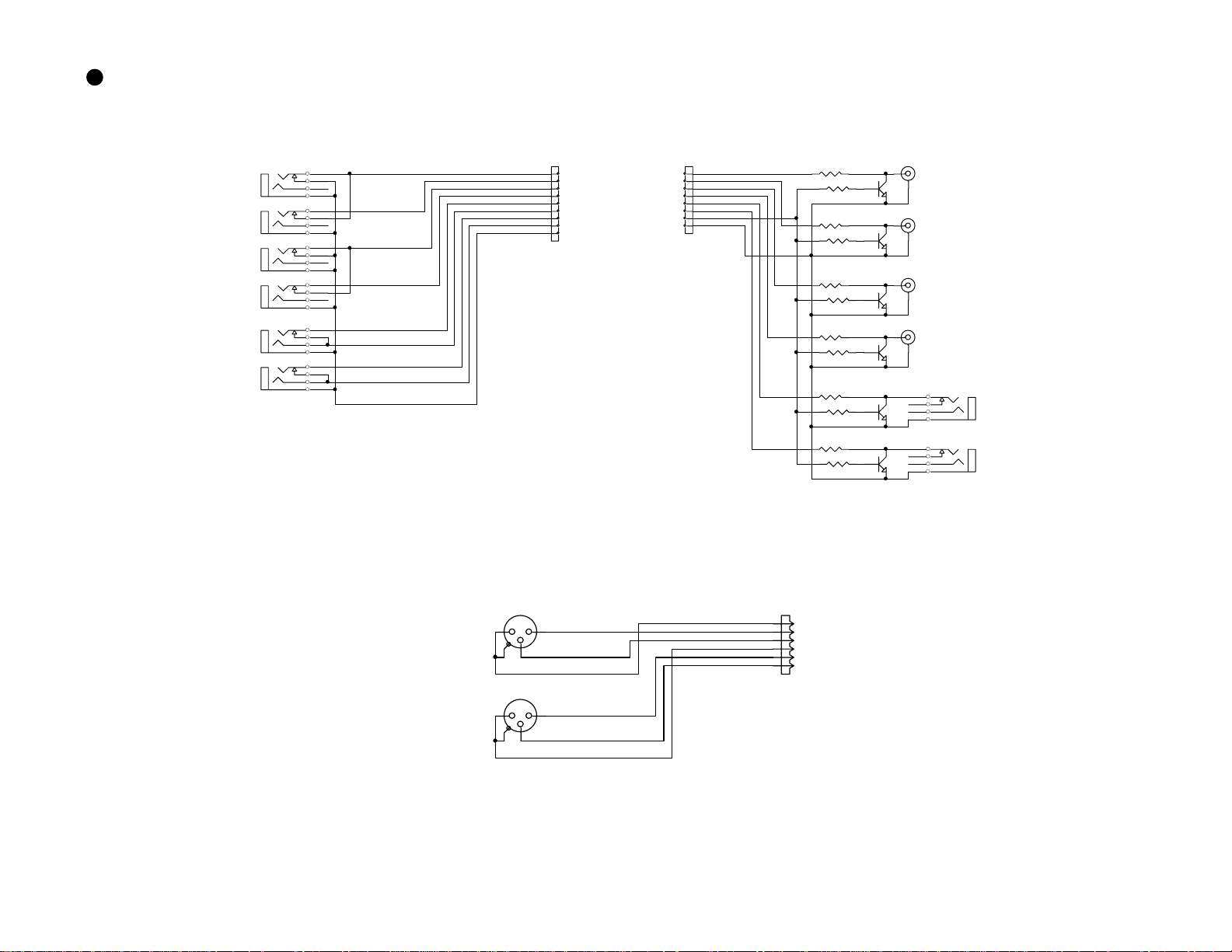
50
FD-8
ANALOG I/O & XLR
J35
AUX R T N 1
L/MONO
J36
R
J37
AUX R T N 2
L/MONO
J38
R
J39
INSERT7
J40
INSERT8
AUX RTN 1 L
AUX RTN 1 R
AUX RTN 2 L
AUX RTN 2 R
INSERT7 SEND
RTN
INSERT8 SEND
RTN
AGND
1
2
3
4
5
6
7
8
9
AUX R T N
INSERT
J11
J10
OUTPUT
1
2
3
4
5
6
7
8
STEREO L
STEREO R
MONITOR L
MONITOR R
AUX1
AUX2
MUTE
AGND
R7 10K
R2
1k
R8 10K
R3
1k
R9 10K
R4
1k
R10 10K
R5
1k
R11 10K
R6
1k
R12 10K
R1
1k
2SC 2878
J31A
ST EREO OU T L
Q1
J31B
2SC 2878
ST EREO OU T R
Q2
J32A
2SC 2878
MONITOR OUT L
Q3
J32B
2SC 2878
MONITOR OUT R
Q4
J33
2SC 2878
Q5
AUX SEND 1
J34
2SC 2878
Q6
AUX SEND 2
J1
INPUT7
BAL
J2
INPUT8
BAL
12
3
2
1
3
AGND
INPUT7H
INPUT7C
AGND
INPUT8H
INPUT8C
1
2
3
4
5
6
J3
INPUT B A L
Page 51

DISPLAY, ROOT (1/3)
W1
1
2
3
BOADIN 9P
4
5
6
DGND
7
D+5
8
9
A-12
To MAIN
DGND
C1
10/16
C3
10/35
R1 0
(F10 JUM PER)
/ATN1
RxD1
TxD1
SCK1
/ATN2
/RST_DISP
D+5
C2
0.1
C4
U2 Non_79L05A C5
0.1
>
<
>
>
<
>
1
GND
0.1A
Vin2-5V
R41
10k
DGND DGND
DGND
Non_10/16C6Non_0.1
3
R7 100
R42
10k
DGND
C10
X1
33p
C11
8MHz
33p
R2 100
C7
470p
R8
1M
SCAN0
SCAN1
SCAN2
SCAN3
SCAN4
1
E101
DGND
(-12V)
Vlcd
/ATN1
R3 100
JOG1
JOG0
1
2
3
DGND
4
5
6
7
8
9
10
11
12
13
14
15
16
D+5
C8
470p
Non_TP
R4 100
R5 100
R6 100
64
PB1/AN1
PB0/AN0
AVSS
TEST
X_OUT
X_IN
VSS
OSC_IN
OSC_OUT
/RESET
P90
P91
P92
P93
P94
IRQ0
P6017P6118P6219P6320P6421P6522P6623P6724P50/INT025P51/INT126P52/INT227P53/INT328P54/INT429P55/INT5/ADTRG30P56/INT6/TMIB31P57/INT7
LED_K0
LED_K1
CPU FD-4 DISPLA Y
LED_K3
LED_K2
LED_K4
57
58
AVCC
PB7/AN759PB6/AN660PB5/AN561PB4/AN462PB3/AN363PB2/AN2
U1
HD6433642A21H
KEY0
LED_K5
LED_K6
LED_K7
/ATN2
470p
C9
D+5
DGND
50
53
49
52
56
51
P31/SI1
P22/TXD
P32/SO1
P14/PWM54P15/IRQ155P16/IRQ2
P30/SCK1
P10/TMOW
P17/IRQ3/TRGV
32
KEY7
KEY1
KEY6
KEY5
KEY4
KEY3
KEY2
P21/RXD
P20/SC K3
P86/FTID
P85/FTIC
P84/FTIB
P83/FTIA
P82/FTOB
P81/FTOA
P80/FTCI
P76/TMOV
P75/TMCIV
P74/TMRIV
48
47
DB7
46
P87
P77
P73
VCC
45
44
43
42
41
40
39
38
37
36
35
34
33
D+5
DGND
KEY[0..7]
LED_K[0..7]
SCAN[0..4]
DB6
DB5
DB4
DB3
DB2
DB1
DB0
E
R/W
RS
C12
0.1
DB[0..7 ]
D+5
DGND
D+5
DGND
Vlcd
LCD
R43_LCD. SCH
DB[0..7 ]
DB[0..7 ]
E
E
R/W
R/W
RS
RS
D+5
D+5
DGND
DGND
Vlcd
Vlcd
KEY & LED
R43_KEY.sch
D+5
D+5
DGND
DGND
LED_A0
LED_A0
LED_A1
LED_A1
KEY[0..7]
KEY[0..7]
LED_K[0..7]
LED_K[0..7]
SCAN[0..4]
SCAN[0..4]
JOG0
JOG0
JOG1
JOG1
51
FD-8
Page 52

52
D
DISPLAY, LCD (2/3)
FD-8
SEG[1. .40]
SEG24
SEG25
SEG26
SEG27
SEG28
SEG23
SEG30
SEG29
80
SEG38
SEG37
SEG36
SEG35
SEG34
SEG33
SEG32
SEG31
SEG1
SEG2
SEG3
SEG11
SEG12
SEG14
SEG15
SEG17
SEG19
SEG20
SEG21
SEG22
SEG6
SEG7
SEG8
SEG9
SEG10
SEG4
SEG5
SEG16
SEG13
SEG24
SEG18
SEG23
SEG32
SEG31
SEG30
SEG29
SEG25
SEG26
SEG27SEG28
SEG28
SEG40
SEG39
SEG38
SEG37
SEG36
SEG35
SEG34
SEG33
R/W
DB[0..7]
DGND
RS
SEG22
1
SEG22
SEG21
2
SEG21
SEG20
3
SEG20
SEG19
4
SEG19
5
SEG18
SEG18
SEG17
6
SEG17
SEG16
7
SEG16
SEG15
8
SEG15
SEG14
9
SEG14
SEG13
10
SEG13
SEG12
11
SEG12
SEG11
12
SEG11
SEG10
13
SEG10
SEG9
14
SEG 9
D+5
D+5
DB[0..7]
DGND
Vlcd
D+5
Non_1/ 50
C13
R10
(F5 Jum per)
0
U5
3
1
2
Non_LA5640N
1
R16 5kB
5
Lo< CONTRAST >Hi
DGND
Vlcd
E
SEG8
15
SEG 8
SEG7
16
SEG 7
SEG6
17
SEG 6
SEG5
18
SEG 5
SEG4
19
SEG 4
SEG3
20
SEG 3
SEG2
21
SEG 2
22
SEG1
SEG 1
23
GND
24
DGND
R11 1k
2
3
R43 10k
4
OSC_I
R9
200k
R12 1k R13 1k
R15 1kR14 1k
Vlcd
U3
HD44 780U
LCD DR IVER
OSC_O25V126V227V328V429V530CL131CL232VCC33M34D35RS36R/W37E38DB039DB1
SEG3865SEG3766SEG3667SEG3568SEG3469SEG3370SEG3271SEG3172SEG3073SEG2974SEG2875SEG2776SEG2677SEG2578SEG2479SEG23
SEG39
SEG40
COM16
COM15
COM14
COM13
COM12
COM11
COM10
COM 9
COM 8
COM 7
COM 6
COM 5
COM 4
COM 3
COM 2
COM 1
DB7
DB6
DB5
DB4
DB3
DB2
40
DB0
DB1
DGND
SEG39
64
SEG40
63
62
COM16
COM15
61
60
COM14
59
COM13
58
COM12
57
COM11
56
COM10
COM9
COM7
COM6
COM5
COM4
COM3
COM2
COM1
DB7
DB6
DB5
DB4
DB3
DB2
D+5
DGND
COM[1..1 6 ]
COM[1..1 6 ]
L1
LAMP
SEG5
55
54
53
52
51
50
49
48
47
46
45
44
43
42
41
D+5
C14
0.1
9
SEG11SEG22SEG33SEG44SEG55SEG66SEG77SEG88SEG9
SEG541SEG442SEG343SEG244SEG145COM946COM1047COM1148COM1249COM1350COM1451COM1552COM1653SEG654SEG755SEG856SEG957SEG1058SEG1659SEG3760SEG3861SEG3962SEG4063SEG1364SEG1865SEG2366SEG2867SEG33
SEG1
SEG2
SEG3
SEG4
COM9
COM10
COM11
COM12
SEG1010SEG1111SEG1212SEG1313SEG1414SEG1515SEG16
COM13
COM14
COM15
COM16
17
16
SEG6
SEG7
SEG8
SEG9
SEG10
SEG16
SEG38
SEG37
U4
LCD_ FD4
SEG40
SEG39
SEG13
SEG18
SEG23
29
SEG2828SEG2727SEG2626SEG2525SEG2424SEG2323SEG2222SEG2121SEG2020SEG1919SEG1818SEG17
COM969COM1070COM1171COM1272COM1373COM774COM675COM576COM477COM378COM279COM1
68
SEG33
COM5
COM6
COM7
COM9
COM10
COM11
COM12
COM13
SEG4040SEG3939SEG3838SEG3737SEG3636SEG3535SEG3434SEG3333SEG3232SEG3131SEG3030SEG29
D+5
L2
DGN
LAMP
80
COM1
COM2
COM3
COM4
Page 53

DISPLAY, KEY & LED (3/3)
SCAN[0.. 4 ]
KEY[0..7]
LED _A 0
LED _A 1
LED _K [0. . 7]
JOG0
JOG1
SCAN[0.. 4 ]
R39 1k
R40 1k
LED _K [0. . 7]
KEY[0..7]
2SA 115 0
2SA 115 0
D+5
R19 10k
R18 10kR17 10 0k
C15
0.01
DGND
R21 10kR20 10 0k
C16
0.01
LED_R
D48
LED_G
D56
DGND
D7
S7
S/R 7S/R 8
D15
S15
Non
Non
D23
S23
EDI T
D31
S31
D39
R29 22k
Non_LED_R
LED _K 6
DGND
S/R 7S/R 8
LED_R
D47
D55
R37 110
KEY7
SCAN0
D8
S8
SCAN1
D16
S16
SC RU B
SCAN2
D24
S24
UNDO/REDO
SCAN3
D32
S32
REW
SCAN4
D40
S40 S39 S38 S37 S36
Non_T ACT Non_T ACT No n_TAC T Non_T ACT
R30 22k
DGND
D+5
Q1
Q2
SC RU B
R38 110
LED _K 7
KEY6
R22 10k
D+5
DGND
D6
S6
D14
S14
D22
S22
ST OR E
D30
S30
STO PPLAY
D38
DGND
ST OR E
R36 110
LED _K 5
R28 22k
1
2
3
LED_R
D46
LED_G
D54
4
U6
J1
J1
J2
COM
J1
JOG
5
D5
S5
D4
S4
D3
S3
D2
S2
D1
S1
S/R 1S/R 2S/R 3S/R 4S/R 5S/R 6
D13
S13
Clip INClip OUT
D21
S21
HOLD
D29
S29
REC
D37
R27 22k
KEY5
DGND
LED_R
D45
S/R 5S/R 6
LED_G
D53
HD ACCE SS
R35 110
LED _K 4
D12
D20
Non Non
D28
D36
KEY4
LED _K 3
S12
D11
S11
D10
S10
D9
EN D Pu n c h OUT Punch IN START
S20 S19
D19
Non_T ACT Non_T ACT
S28
D27
S27
D18
S18
D17
EXECUTEEXI T
D26
S26
D25
AU TO PLY/RTN LO CATE SHI FTF FWD
VAR INon Non Non Non
DGND
S/R 4
Non_LED_G
R34 110
R26 22k
LED_R
D44
D52
D35
S35
SETUP TIM EBAS E SEL D ISP SEL
R25 22k
KEY3
DGND
S/R 3
PLAY
R33 110
LED _K 2
LED_R
D43
LED_G
D51
D34
S34
R24 22k
KEY2
DGND
S/R 2
STO P
R32 110
LED _K 1
LED_R
D42
LED_G
D50
D33
KEY1
LED _K 0
S9
S17
S25
S33
DGND
S/R 1
REC
R31 110
R23 22k
LED_R
D41
LED_R
D49
KEY0
53
FD-8
Page 54

54
POWER
AC IN
J2
AC IN
FD-8
S1
F1
SW1-2 BL
250VAC/0.8A
L4
6HOLE
L1
0.1/250VAC
C1
4
1
LINE FILTER 1mH/2.2A
3
2
1
L5
6HOLE
1 2
3
4
C21
0.0022/250VAC
C22
2 3
0.0022/250VAC
W1
LINE FILTER 19mH/0.5A
non
1
L3
4
1
2 3
2
D1
~
4
DB-S
-+
~
3
U1
CSD
IPD MIP
C24
non
1
C13
100/400V
3
2
1
0.01/630V
C3
0.1
C7
R4
390P/500V
33/0.5W
C6
0.0022/250VAC
6
7
D4
MA649
8
D6
11
EK13
C17
330/25V
10
D5
EK13
9
C18
330/25V
U2
4
AKEC
3
ON3171
AN1431T
1
T1
C2
R1
100k/2W
2
D3
DIN60
3
5
4
C14
TRANSE 3
47/25V
D2
MA171
R2
6.2
R3
C4
6.2
0.1
C5
0.0022/250VAC
L2
10uH/2A
C15
470/25V
C9
0.01
C10
0.01
R5
75
1
2
12
U5
R6
R7
470
10k
C8
R8
10k
0.1
3
R9
10k
U3
NJM7812A
Vin3+12V
GND
Vin2-12V
U4
NJM7912A
C16
470/25V
1
1A
C11
0.01
2
3
GND
1A
1
C12
0.01
C20
330/25V
DGND
330/25V
C19
D+5
J1
1
2
3
4
5
A+12
6
AGND
7
8
A-12
8263M8P
Page 55

MAIN, ROOT (1/10)
AGND HP
REC_L
REC_R
REC I N
A+12
AGND
A-12
MUTE
TO MIXER
J10
8283M7P
RCA-JACK-SW
AGND
1
2
3
4
5
6
7
L11
L14
J101
1
J201
1
RCA-JACK-SW
TO DISPLAY
L7
TO DCDC
A+12
21
21
21
21
L13
W101
NON
3
2
L101
W201
NON
3
2
L201
TO HDD
A-12 AGND
REC_L
REC_R
21
21
TP
W9
1
DGND
W3
-12V
GND2
GND2
+12V
GND1
GND1
+5V
+5V
BOADIN-8P
W1
NC
non
AD-DA
MUTE
MUTE
REC_L
REC_L
REC_R
REC_R
A+12
A+12
A+12
A-12
A-12
A-12
A+5
A+5
A+5
AGND
AGND
AGND
D+5_1
D+5_1
D+5_1
DGND1
DGND1
DGND1
D+5
D+5
D+5
DGND
DGND
DGND
R_ADDA.S CH
A+12
8
7
6
5
4
3
2
1
A-12
1
D+5HD
2
3
4
DGND
AD_D1
AD_D1
DA_D[1..4]
DA_D[1..4]
/RST_ADDA
/RST_ADDA
R_MUTE[1..8]
R_MUTE[1..8]
MSCK
MSCK
/MUTE
/MUTE
LRCK
LRCK
AD_D1
DA_D[1..4]
LRCK
CONN ECT
BCK
MSCK
C1
non
C7
non
C10
10/16
C14
10/16
BCK
BCK
/RST
/RST
AUDIO_IF
AD_D1
AD_D1
DA_D[1..4]
DA_D[1..4]
LRCK
LRCK
BCK
BCK
MSCK
MSCK
VCO+5
VCO+5
VCO+5
VCOGND 28MHZ
VCOGND 28MHZ
VCOGND
D+5
DGND
DGND
DGND
AUDIO_IF.SCH
78M05
U1
I3O
C2
0.1
C8
0.1
C11
0.1
C15
0.1
2
78M05
U2
I3O
2
L2
1/4 ISOLATION
L3
1/4 ISOLATION
G
G
/RST_ADDA
/MUTE
/RST
R_MUTE[1..8]
1
C3
10/16
1
C12
non
C16
non
C9
10/16
D[0..15]
D[0..15]
A[0..18]
A[0..18]
SCSI_T MOUT
SCSI_T MOUT
SC_INT7I
SC_INT7I
/CS_IDE
/CS_IDE
/DACK 1
/DACK 1
/AIRQ1
/AIRQ1
IORDY1
IORDY1
/DREQ1
/DREQ1
/ATA_INT1
/ATA_INT1
SCSI_CS
SCSI_CS
DMA_SEL
DMA_SEL
A+5
AGND
VCO+5
VCOGND
D+5
C13
non
DGND
D+5HD
C17
non
DGND
D[0..15]
A[0..18]
C4
0.1
DGND
/RD
/WR
SCSI_T MOUT
SC_INT7I
28MHZ
/CS_IDE
/DACK 1
/AIRQ1
IORDY1
/DREQ1
/ATA_INT1
/RST
SCSI_CS
DMA_SEL
1/4 ISOLATION
C18
0.1
/CS1
L1
CONN ECT
D+5_1
C6
non
C5
non
DGND1
/RD
/RD
/WR
/WR
/CS1
/CS1
/RSTD+5
/RSTD+5
CPU
CPU.SC H
CPUAD-DA GATE ARRAY
D[0..15]
D[0..15]
A[0..18]
A[0..18]
/RD
/RD
/WR
/WR
SCSI_T MOUT
SCSI_T MOUT
SC_INT7I
SC_INT7I
28MHZ
28MHZ
/CS1
/CS1
/CS_IDE
/CS_IDE
/DACK 1
/DACK 1
/AIRQ1
/AIRQ1
IORDY1
IORDY1
/DREQ1
/DREQ1
/ATA_INT1
/ATA_INT1
/RST
/RST
SCSI_CS
SCSI_CS
DMA_SEL
DMA_SEL
/RST_ADDA
/RST_ADDA
/MUTE
/MUTE
R_MUTE[1..8]
R_MUTE[1..8]
DGND
DGND
A-12
A-12
A-12
D+5
D+5
D+5
DGND
55
FD-8
Page 56

56
MAIN, CPU (2/10)
A-12
D+5
DGND
MEMORY
MEMORY
MEMORY. SCH
D[0..15]
GR
A[0..18]
/WR
GR
/RD
TO
DISPLAY
FD-8
D+5
U20
1
DTA114EK
23
R79
1
R_MUTE 1
R_MUTE 2
R_MUTE 3
ADDA
R_MUTE [1..8 ]
A-12
D+5
DGND
GND
/WR
/RD
J7
1
/ATN1
2
RXD1
3
TXD1
4
SCK1
5
/ATN2
/RST_DISP
6
7
DGND
8
9
8283M9P
A-12
R_MUTE [1..8 ]
S1
non
123
R67
DGND
/EPROM
/EPROM
FM_RDY
FM_RDY
D[0..15]
D[0..15]
D[0..15]
A[0..18]
A[0..18]
A[0..18]
D+5
D+5
D+5
DGND
DGND
DGND
RDWR
RDWR
RDWR
/CS0
/CS0
/CS0
/CS2
/CS2
/CS2
/RAS
/RAS
/RAS
/LCAS
/LCAS
/LCAS
/UCAS
/UCAS
/UCAS
/RD
/RD
/RD
/WR
/WR
/WR
D[0..15]
A[0..18]
A0
C79
NON
DGND
D+5
R_MUTE 4
R_MUTE 5
R_MUTE 6
R_MUTE 7
D+5
R_MUTE 8
R45
10K
NON
R63
100
R65
100
D+5
U25
1
DTA114EK
23
R83
1
U26
10K
DTA114EK
23
1
R84
10K
R86
A-12
/RST_ADDA
ADDA
/MUTE
A0
A1
A2
A3
A4
A5
A6
A7
A8
A9
A10
A11
A12
A13
A14
A15
A16
A17
A18
R62
100
R64
100
10K
10K
R85
/EPROM
FM_RDY
DGND
GR
R43 100
R44 100
U27
DTA114EK
23
1
U28
DTA114EK
23
/DREQ1
/DACK1
R46
10K
DGND
/AIRQ1
/ATA_INT1
GR
IORDY1
SCSI_CS
GR
/CS_IDE
/ATN1
RXD1
TXD1
SCK1
/ATN2
/RST_DISP
C78
470P
DGND
10K
1
R80
10K
1
R81
10K
R82
10K
A-12
R77
10K
DGND
1
2
3
4
5
6
7
8
9
10
11
12
13
14
15
16
17
18
19
20
21
22
23
24
25
26
27
28
C95
100p
SCSI_CS
DGND
/CS_IDE
PE14/AH
PE15/IRQOUT
VSS
PC0/A0
PC1/A1
PC2/A2
PC3/A3
PC4/A4
PC5/A5
PC6/A6
PC7/A7
PC8/A8
PC9/A9
PC10/A10
PC11/A11
PC12/A12
PC13/A13
PC14/A14
PC15/A15
PB0/A16
VCC
PB1/A17
VSS
PB2/RAS
PB3/CASL
PB4/CASH
VSS
PB5/RDWR
112
PE13/MRES
PB6/A18/BACK
29
U24A
14
74HC32
3
C92
NON
U21
DTA114EK
23
U22
23
DTA114EK
U23
23
DTA114EK
100
108
110
111
109
107
VSS
PE9
PE10
PE11
PE12
PB7/A19/BREQ30PB8/A20/WAIT31PB9/A21/ADTRG32VSS33PA14/RD34WDTOVF35PA13/WRH36VCC37PA12/WRL38VSS39PA11/CS140PA10/CS041PA9/IRQ342PA8/IRQ243PA7/CS344PA6/CS245PA5/SCK146PA4/TXD147PA3/RXD148PA2/SCK049PA1/TXD050PA0/RXD051PD15/D1552PD14/D1453PD13/D1354VSS
D+5
DGND
1
2
DGND
96
99
101
102
104
105
106
103
VSS
PE5
PE6
PE7
PE8
VCC
SH7042
C93
0.01
R78
100
90
97
VSS
AVSS
AVCC
PF0/AN091PF1/AN192PF2/AN293PF3/AN394PF4/AN495PF5/AN5
PF6/AN698PF7/AN7
U15
J8
L21
2
SC_INT7I
21
BEAD
1
DGND
U13
R48
2
10K
6
7
1
C72
1/50
GR
8
U24C
74HC32
11
U24D
74HC32
U12B
74HC14
L17
21
BEAD
L18
21
BEAD
L19
21
BEAD
L20
21
BEAD
DGND
GR
HP JACK MONO
TP4
NON
TP3
NON
9
10
12
13
34
10
13
14
3
6
7
PUNCH IN/OUT
D+5
C73
0.01
DGND
DGND
DGND
9811
12
DIN-5P
4
MIDI IN
5
123
J9B
17
18
214
5
DIN-5P
MIDI OUT
4
5
123
J9A
15
16
D+5
1 3
1 3
1312
D+5
TP5
NON
X3
7MHz
4
D3
DAN202K
D4
DAN202K
/RST
3
8
R68
330
C75
C69
0.1
D+5
6
U11
PC900
V
K
O
A
G
5
DGND
DTC114EK
U14
213
DGND
SC_INT7I
R72
NON
C74
33p
33p
GR
1
2
DAN202K
TP
TP6
OC
RST
28MHZ
MD=2
CLOCK= x4
C91
10/16
1 3
D5
D+5
SCSI_TMOUT
1
1
TP
TP7
5
NJM2103M
VSC
VCC
VSB
VSA
CT
GND
4
DGND
DGND
D+5
DGND
R76
220
R74
220
R75
220
SCSI_TMOUT
/PUNCH_I/O
DMA_SEL
SCSI_TMOUT
/RST_DISP
85
87
86
88
89
PE4
PE0/DREQ0
PE2/DREQ1
PE1/DRAK0
PE3/DRAK1
PD12/D12
56
55
D12
D13
D14
D15
/CS1
C77
100p
84
RES/(V PP)
83
PA15/CK
82
PLLVSS
81
PLLCAP
80
PLLVCC
79
MD0
78
MD1
77
VCC
76
NMI
75
MD2
74
EXTAL
73
MD3
72
XTAL
71
VSS
70
PD0/D0
69
PD1/D1
68
PD2/D2
67
PD3/D3
66
PD4/D4
65
VCC
64
PD5/D5
63
PD6/D6
62
PD7/D7
61
VSS
60
PD8/D8
59
PD9/D9
58
PD10/D10
57
PD11/D11
R51
10K
GR
/CS1
98
U12D
74HC14
DGND
C76
0.01
GR
D+5
R52 10 0
/RST
U12E
74HC14
1110
U12F
74HC14
D+5
C909
C94
0.01
0.01
R69
14
2.2k
DGND
1 2
R70
D+5
U12A
74HC14
330
D0
D1
D2
D3
D4
D5
D6
D7
D8
D9
D10
D11
RXD0
U24B
74HC32
6
R71
10k
R47
10K
C88
0.1
C70
0.1
C71
0.01
R50
1K
5 6
TXD0
U12C
74HC14
4
5
R73
0
DGND
R66
R49
1.5K
330
Page 57

MAIN, MEMORY (3/10)
EPROM1 EPRO M2 FLASH MEMORY DRAM
U31
A1
12
A0
A2
11
A1
A3
10
A2
A4
9
A3
A5
8
A4
A6
7
A5
A7
6
A6
A8
5
A7
A9
27
A8
A10 A10
26
A9
A11
23
A10
A12
25
A11
A13
4
A12
A14
28
A13
A15
29
A14
A16
3
A15
A17 A17
2
A16
30
A17
31
A18
HN27C4001 G-S OCKET
D+5
DGND
FM_RDY
/CS0
/CS2
/EPROM
D+5
DGND
D0
13
D0
D1
14
D1
D2
15
D2
D3
17
D3
D4
18
D4
D5
19
D5
D6
20
D6
D7
21
D7
24
OE
22
CE
VPP
VCC
GND
R91
10K
R92
NON
/CS0
/CS2
/CS2
/CS0
DGND
DGND GND
1
32
16
Under 2M
2M of 4M
D+5
3
6
10
13
1
D+5 D+5
C99
0.01
DGND DGND
R88
NON
U29
1A21Y
1B
2A52Y
2B
3A113Y
3B
4A144Y
4B
A/B
G15VCC
74HC157
4
7
9
12
16
/CS_EPROM
/CS_FL MEM
DGND
U32
A1
12
A0
A2
11
A1
A3
10
A2
A4
9
A3
A5
8
A4
A6
7
A5
A7
6
A6
A8
5
A7
A9
27
A8
26
A9
A11
23
A10
A12
25
A11
A13
4
A12
A14
28
A13
A15
29
A14
A16
3
A15
2
A16
30
A17
31
A18
HN27C4001 G-S OCKET
D+5
C97
0.01
D8
13
D0
D9
14
D1
D10
15
D2
D11
17
D3
D12
18
D4
D13
19
D5
D14
20
D6
D15
21
D7
24
OE
22
CE
1
VPP
32
VCC
16
GND
DGNDDGND
C98
D+5
0.01
C100
NON
DGND
U30
A1
25
A0
A2
24
A1
A3
23
A2
A4
22
A3
A5
21
A4
A6
20
A5
A7
19
A6
A8
18
A7
A9
8
A8
A10
7
A9
A11
6
A10
A12
5
A11
A13
4
A12
A14
3
A13
A15
2
A14
A16
1
A15
A17
48
A16
A18A18 A18
17
A17
16
A18
37
VCC
27
VSS
46
VSS
M29F400 T-400
D+5
R87
10K
RESET
RY/BG
D0
29
DQ0
D1
31
DQ1
D2
33
DQ2
D3
35
DQ3
D4
38
DQ4
D5
40
DQ5
D6
42
DQ6
D7
44
DQ7
D8
30
DQ8
D9
32
DQ9
D10
34
DQ10
D11
36
DQ11
D12
39
DQ12
D13
41
DQ13
D14
43
DQ14
D15
45
DQ15
28
OE
26
CE
11
WE
D+5
12
15
47
BYTE
/RD
/RD
/WR
/WR
/RAS
/RAS
RDWR
RDWR
D[0..15]
A[0..18]
U33
1
VCC
D0
2
I/O0
D1
3
I/O1
D2
4
I/O2
D3
5
I/O3
6
VCC
D4
7
I/O4
D5
8
I/O5
D6
9
I/O6
D7 D8
10
I/O7
11
NC
12
NC
13
WE
14
RAS
15
NC
16
NC
A1
17
A0
A2
18
A1
A3
19
A2
A4 A5
20
A3
VCC21VSS
D+5
HM51W181 60 J/A L J
C96
0.01
DGND
I/O15
I/O14
I/O13
I/O12
I/O11
I/O10
LCAS
UCAS
42
VSS
41
40
39
38
37
VSS
36
35
34
I/O9
33
I/O8
32
NC
31
30
29
OE
28
A9
27
A8
26
A7
25
A6
24
A5
23
A4
22
D[0..15]
A[0..18]
D15
D14
D13
D12
D11
D10
D9
A10
A9
A8
A7
A6
/LCAS
/UCAS
57
FD-8
Page 58

58
FD-8
MAIN, GATE ARRAY (4/10)
VCO+5
VCO+5 A[0..18]
POWER
VCOGND /CS1
VCOGND
DGND
D+5
/ATA_RST
/ATA_RST
ATA[0..4]
ATA[0..4]
/DMA_RD
/DMA_RD
/DMA_WR
/DMA_WR
DMA_SEL
DMA_SEL
/SCSI_DREQ
/SCSI_DREQ
SCSI_TMOU T
SCSI_TMOU T
DD[0..17]
DD[0..17]
DMARQ
DMARQ
/DIOW
/DIOW
IORDY_I
IORDY_I
/DMACK
/DMACK
/PDIAG
/PDIAG
INTRQ
INTRQ
/CS1FX
/CS1FX
/CS3FX
/CS3FX
/SCSI_CS
/SCSI_CS
SC_INT7I
SC_INT7I
28MHz
28MHz
DGND
DGND
D+5
DGND
DD[0..17]
/DIOR
/DIOR
D+5
D+5
POWER
SCSI
SCSI.SCH
GND
/ATA_RST
DMARQ
/DIOW
/DIOR
IORDY_I
/DMACK
/PDIAG
INTRQ
/CS1FX
/CS3FX
ATA[0..4]
/DMA_RD
/DMA_WR
/SCSI_CS
DMA_SEL
/SCSI_DREQ
SC_INT7I
28MHZ
D+5
GND
D+5
C24
C22
0.01
0.01
C21
10/16
DGND
D+5
R96
R95
1K
1K
R9
5.6K
C29
NON
D+5
DGND
R8
10K
C23
0.01
C30
470P
DGND
DGND
C25
0.01
DD7
DD8
DD6
DD9
DD5
DD10
DD4
DD11
DD3
DD12
DD2
DD13
DD1
DD14
DD0
DD15
ATA1
ATA0
ATA2
R12
100
CPU
SC_INT7I AD_D1
SCSI_TMOU T
28MHZ
C28
W2
100p
NON
C910
DA_D[1..4]
ADDA
ATA3
ATA4
NON
DA_D[1..4]
LRCK
BCK
MSCK
D0D1D2D3D4D5D6D7D8D9D10
34
36
35
26
D727D628D529D430D331D232D133D0
NC
VDD
37
NC
38
VSS
39
ATA_RES
40
ATA_D7
41
ATA_D8
42
ATA_D6
43
ATA_D9
44
VSS
45
ATA_D5
46
ATA_D10
47
ATA_D4
48
ATA_D11
49
ATA_D3
50
ATA_D12
51
ATA_D2
52
ATA_D13
53
ATA_D1
54
VDD
55
VDD
56
ATA_D14
57
ATA_D0
58
ATA_D15
59
DMARQ
60
DIOW
61
DIOR
62
IORDY_I
63
DMACK
64
VSS
65
VSS
66
INTRQ
67
ATA_A1
68
ATA_A0
69
ATA_A2
70
CS1FX
71
VSS
72
VDD
VDD73VSS74CS3FX75DMA_RD76DMA_WR77SCSI_CS78SCSI_INT79SCSI_DRE Q80SCSI_A381SCSI_A482SCSI_A583AD_DATA_1284AD_DATA_3485AD_DATA_5686AD_DATA_7887AD_DATA_LR88VSS89VDD90DA_DATA_1291DA_DATA_3492DA_DATA_5693DA_DATA_7894DA_DATA_LR95BCK96LRCK97MCLK98VSS99XO1
SCSI_CS
DMA_SEL
AD_D1
R97
1M
1110
U6E
74HCU04
20MHz
DA_D1
X4
NON
DA_D2
C911
DA_D3
0
DGND
DA_D4
25
VSS
23
D924D8
R1 100
R2
R3
R4
D11
D12
D13
D14
D15
A9A1A2A3A4A5A6A7A8
C912
14
18
16
17
VSS15VSS
D15
D1419D1320D1221D1122D10
VDD
U5
GA2
100
100
100
R6 100
R5 100
R13 330
4
1
3
5
2
33p
CS
A86A77A68A59A410A311A212A113A0
VSS
VDD
CS_IDE
IORDY_O
144
VDD
143
VSS
142
WR
141
RD
140
NC
139
ATA_INT
138
MLRCK
137
DACK_I
136
VSS
135
ATA_DREQ
134
RST
133
SLAVE
132
TCRC
131
TST2
130
TCK2
129
VDD
128
DIGITAL_OUT_2
127
DIGITAL_IN_2
126
DIGITAL_OUT_1
125
DIGITAL_IN_1
124
TEST
123
EXT_MCLK2
122
FCONT2
121
PD2
120
PLL_SEL
119
FCONT1
118
PD1
117
EXT_MCLK1
116
VSS
115
VDD
114
VARI_256FS
113
VARI_FS
112
SLAVE_M SCK
111
SLAVE_MLRC K
110
NC
109
NC
XI1
VDD
VSS
XO2
XI2
VDD
VSS
100
101
102
103
104
105
106
107NC108
R14
1M
56
U6C
74HCU04
R15
0
X1
22.5792MHz
C31
C32
22p
22p
DGND
DGND
D+5
14
C34
0.01
1 2
U6A
74HCU04
DGND
/ATA_INT1
/AIRQ1
/DACK1
/DREQ1
C27
470p
DGND
VCO1
PLL_SEL
PLL_SEL
FCONT1
FCONT1
PD1
PD1
EXT_MCLK1
EXT_MCLK1
VCO1.SCH
C20
R7
0.01
100
D+5
R10
R16
3.3K
330
R11
2.2K
R98
100
R17
1M
U6D
98
74HCU04
R18
0
X2
16.384MHz
C35
C36
22p
22p
3 4
U6B
74HCU04
CPU
VARI_512FS
VARI_512FS
VARI/EXT_LRCK
VARI/EXT_LRCK
VCO+5
VCO+5
VCO+5
VCOGND
VCOGND
D+5
2
1
3
DATA OUT(OPT)
D+5
1
3
2
DATA IN(OPT)
J4
GPIF32T
J5
GPIF32R
EXT_LRCK
VCOGND
4
5
6
4
5
6
VCO1
DGND
C26
10/16
C33
0.01
DGND
D[0..15]
A[0..18]
ADAC
/RST
/RST
/CS1
/CS1
/CS_GA2
/CS_GA2
MLRCK /WR
MLRCK /WR
VARI_256FS
VARI_256FS
VARI_FS
VARI_FS
VARI_512FS
VARI_512FS
VARI/EXT_LRCK
VARI/EXT_LRCK
EXT_LRCK
EXT_LRCK
adac.SCH
D[0..15]
D[0..15]
A[0..18]
A[0..18]
/CS_IDE
IORDY1
DGND
DGND
D[0..15]
/CS_IDE
IORDY1
CPU
CPU
/WR
CPU
/RD
CPU
/RST
/CS1
A[0..1 8]
D[0..1 5]
/WR
/RD
/RST
/RD
/RD
D+5
D+5
D+5
DGND
Page 59

MAIN, SCSI I/F (5/10)
/ATA_RST
GA
DMARQ
IORDY_I
INTRQ
J12
1
2
3
4
5
6
/ATA_RST
7
DGND
8
DD7
9
DD8
10
DD6
11
DD9
12
DD5
13
DD10
14
DD4
15
DD11
16
DD3
17
DD12
18
DD2
19
DD13
20
DD1
21
DD14
22
DD0
23
DD15
24
DGND
25
26
KEYPIN
DMARQ
27
DGND
28
/DIOW
TO IDE HD
29
DGND
30
/DIOR
31
DGND
32
IORDY
33
34
35
DMACK
DGND
36
INTRQ
37
38
/IOCS16
ATA1
39
/PDIAG
40
ATA0
41
ATA2
42
/CS1FX
43
/CS3FX
44
45
/DASP
DGND
46
47
48
49
50
/PDIAG
GA
/CS1FX
/CS3FX
DD[0..17]
GA
ATA[0..4]
/DMA_RD
GA
/DMA_WR
/SCSI_CS
GA
SC_INT7I
/SCSI_DR EQ
GA
28MHZ
CPU
SCSI_T MOUT
D+5HD
DGND
W6
W7 NON
W8
NON
DGND
ATA[0..4]
DMA_RDB
DMA_WRB
SCSI_CS B
SC_INT7I
SC_DRE QB
28MHZ
D+5
R29
DD[0..17]
DD15
DD14
DD13
DD12
DD9
DD11
DD7
DD10
DD8
NON
/DIOW
GA
/DIOR
/DMACK
D+5
R28
NON
R27
0
W5
2
1
BOADIN-2P
R21 100
ATA0
R22 100
ATA1
R23 100
ATA2
R24 100
ATA3
R25 100
ATA4
C41
NON
C43
DGND
NON
C42
NON
D+5
S9
S17
S16
S15
S14
S13
S12
S11
S10
DD[0..17]
/DMACK
1312
U6F
74HCU04
ATAD0
ATAD1
ATAD2
ATAD3
ATAD4
C45
NON
C44
NON
DD16
100
98
99
DGND
BHE
UDP
1
WR
2
RD
3
VCC
4
VSS
5
CLK
6
RESET
7
INT
8
MODE
9
DBP
10
VSS
11
DB7
12
DB6
13
DB5
14
VCC
15
VSS
16
VSS
17
DB4
18
DB3
19
DB2
20
DB1
21
VSS
22
DB0
23
TEST1
24
TMOUT
25
(OPEN)
DMA WR26DMA RD27VCC28VSS29DMA 030LDMDP31DMD 032DMD 133DMD 234DMD 335DMD 436DMD 537DMD 638DMD 739VSS40DMD 841DMD 942DMD1043DMD1144DMD1245DMD1346DMD1447DMD1548UDMDP49DMBHE
DGND
90
89
92
D891D9
VSS
D1093D1194D1295D1396D1497D15
MB86604L
DD0
DD1
DD2
DD3
DD4
DD5
DD17
ATAD[0..4]
R26
0
R20
NON
4.7K
DD6
U7
DD6
DMA_SEL
ATAD4
DD5
DD4
DD3
DD2
DD1
DD0
DD17
78
77
80
76
81
D082D183D284D385D486D587D688D7
A4
CS0
VSS79CS1
VCC
LDP
50
DD7
DD8
DD9
DD10
DD11
DD12
DD13
DD14
DD15
DD16
S[0..17]
R19 4.7K
CPU
DMACK
ATAD3
75
A3
ATAD2
74
A2
ATAD1
73
A1
ATAD0
72
A0
71
ATN
70
VSS
69
BSY
68
ACK
67
RES
66
VSS
65
VSS
64
VCC
63
MSG
62
SEL
61
C/D
60
REQ
59
VSS
58
I/O
57
TEST2
56
(OPEN )
55
TP
54
VSS
53
VCC
52
DREQ
51
D+5
S5
/ATN
/BSY
S7
/ACK
S6
/RES
S4
/MSG
S1
/SEL
S8
/C/D
S2
/REQ
S0
/I/O
S3
S[0..17]
D+5
U8
1
N.C.
EN
SCSI15
SCSI16
SCSI17
SCSI18
VSS
SCSI1
SCSI29SCSI9
SCSI3
SCSI4
SCSI5
VCC
BH9595FP
C46
10/16
TSD
VM
SCSI14
SCSI13
SCSI12
SCSI11
SCSI10
SCSI8
SCSI7
SCSI6
VCC
C39
0.01
2
/DBP
/DB0
/DB1
/DB2
/DB3
/DB4
/DB5
/DB6
/DB7
D+5
D1
EK13
3
S9
4
S10
5
S11
6
S12
7
8
S13
S14
10
S15
11
S16
12
S17
13
DGND
21
C47
0.1
C48
10/16
DGND
D+5
POWER
DGND
S0
S1
S2
S3
S4
S5
S6
S7
S8
S9
S10
S11
S12
S13
S14
S15
S16
S17
25
24
23
/SEL
S8
22
/BSY
S7
21
/ACK
S6
20
/ATN
S5
19
/RES
S4
18
/I/O
S3
17
/C/D
S2
16
/MSG
S1
15
/REQ
S0
14
D+5
C37
C38
C40
0.01
0.01
0.01
DGND
GND
J6
26
/REQ
1
14
2
/MSG
15
/C/D
3
/I/O
16
4
/RES
17
/ATN
5
/ACK
18
6
/BSY
19
/SEL
7
20
/DBP
/DB0
/DB1
/DB2
/DB3
/DB4
/DB5
/DB6
/TPWR
/DB7
DGND
SCSI
8
21
9
22
10
23
11
24
12
25
13
27
DSUB-25P
59
FD-8
Page 60

60
FD-8
MAIN, ADAC (6/10)
63
62
60
64
65
66
67
68
69
70
71
72
73
74
75
76
77
78
79
80
81
82
83
84
NANDA061NANDA1
NANDAO
NANDB0
NANDB1
NANDBO
NANDC0
NANDC1
NANDCO
NORA0
NORA1
NORAO
NORB0
VSS
VDD
NORB1
NORBO
NORC0
NORC1
NORCO
MIN TEST
NT
TEST0
TEST1
D01D12D23D34D45D56D67D78D89VDD10VSS11D912D1013D1114D1215D1316D1417D1518A019A120A2
D0D1D2D3D4D5D6D7D8D9D10
C53
0.01
VARI/EXT_LRCK
D+5
D+5
53
52
54
VSS
VDD
PA1055PA1156PA1257PA1358PA1459PA15
ADAC
D11
D12
D13
D14
D15
D+5
C56
C55
C54
0.01
0.01
0.01
DGND
A0A1A2
U4
PA043PA144PA245PA346PA447PA548PA649PA750PA851PA9
42
NCO3
41
NCO2
40
NCO1
39
NCO0
38
NCE
37
CA1
36
CA0
35
NMLRCK
34
C256FS
33
C512FS
32
VDD
31
VSS
30
N16BIT
29
NRESET
28
NCS0
27
NRD
26
NWR
25
A6
24
ADAC
A5
23
A4
A3
22
DGND
D[0..15]
A5
A4
A3
21
VARI _FS
EXT_LRCK
VARI /E XT
C87
C86
non
non
DGND
63
62
64
NANDAO
NANDB0
65
NANDB1
66
NANDBO
67
NANDC0
68
NANDC1
69
NANDCO
70
NORA0
71
NORA1
72
NORAO
73
NORB0
74
VSS
75
VDD
76
NORB1
77
NORBO
78
NORC0
79
NORC1
80
NORCO
81
MIN TEST
82
NT
83
TEST0
84
TEST1
D01D12D23D34D45D56D67D78D89VDD10VSS11D912D1013D1114D1215D1316D1417D1518A019A120A2
D0D1D2D3D4D5D6D7D8D9D10
53
60
52
54
VSS
VDD
PA1055PA1156PA1257PA1358PA1459PA15
NANDA061NANDA1
ADAC
D11
D12
D13
D14
D15
C81
C80
0.01
0.01
A0A1A2
C82
0.01
U3
PA043PA144PA245PA346PA447PA548PA649PA750PA851PA9
42
NCO3
41
NCO2
40
NCO1
39
NCO0
38
NCE
37
CA1
CA0
NMLRCK
C256FS
C512FS
VDD
VSS
N16BIT
NRESET
NCS0
NRD
NWR
A6
A5
A4
A3
ADAC
21
D+5
C83
0.01
DGND
A11
A10
36
35
34
33
32
31
30
29
28
27
26
A6A6
25
24
A5
23
A4
A3
22
C85
non
DGND DGND
DGND
D+5
DGND
EXT_LRCK
MLRCK
/CS_GA2
/CS1
C84
non
A[0..18]
D[0..15]
A[0..18]
D[0..15]
MLRCK
VARI_512FS
/CS_GA2
VARI_256FS
EXT_LRCK
VARI_FS
VARI/EXT_LRCK
/RD
/RST
/WR
/CS1
CPU
GR
CPU
Page 61

MAIN, ROOT, ADDA (7/10)
MIXE R
MIXE R
AGND
TO
TO
/MUTE
ADDA ADDA_OU T
ADDA_DG
AOUT1+
AOUT1+
AOUT2+
AOUT2+
AOUT3+
AOUT3+
AOUT4+
AOUT4+
AOUT5+
AOUT5+
AOUT6+
AOUT6+
AOUT7+
AOUT7+
AOUT8+
AOUT8+
A-12
AOUT1+
AOUT2+
AOUT3+
AOUT4+
AOUT5+
AOUT6+
AOUT7+
AOUT8+
A+12
AGND
AIN1+
AIN1+
AIN1-
AIN1-
AIN2+
AIN2+
AIN2-
AIN2-
A+5
A+5
AGND
AGND
D+5_1
D+5_1
DGND1
DGND1
AD_D1
AD_D1
DA_D[1..4]
DA_D[1..4]
/RST
/RST
RST_ADDA
RST_ADDA
MSCK_A DDA
MSCK_A DDA
LRCK_ADDA
LRCK_ADDA
BCK_ADDA
BCK_ADDA
MSCK_A D
MSCK_A D
ADDA_DG.SCH
ADDA_OUT
AOUT1+ AOUT1
AOUT1+ AOUT1
AOUT2+
AOUT2+
AOUT3+
AOUT3+
AOUT4+
AOUT4+
AOUT5+
AOUT5+
AOUT6+
AOUT6+
AOUT7+
AOUT7+
AOUT8+
AOUT8+
A+12
A+12
A-12
A-12
AGND
AGND
ADDA_OUT.SCH
CPU
R_M U TE[1..8]
A+12
A-12
A+5
AGND
AOUT2
AOUT2
AOUT3
AOUT3
AOUT4
AOUT4
AOUT5
AOUT5
AOUT6
AOUT6
AOUT7
AOUT7
AOUT8
AOUT8
AGND
L102
L302
L103
L303
AOUT1
AOUT2
AOUT3
AOUT4
R_MUT E1
R_MUT E2
R_MUT E3
R_MUT E4
AGND
L502
L702
L503
L703
AOUT5
AOUT6
AOUT7
AOUT8
R_MUT E5
R_MUT E6
R_MUT E7
R_MUT E8
AGND
R_M U TE[1..8]
D+5_1
DGND1
D+5
DGND
DGND
D+5_1
DGND1
D+5
GND
A+12
A-12
A+5
TO
L202
L402
MIXE R
L203
J3
L403
21
21
21
21
L602
L802
L603
L803
21
21
21
21
RP1
1
RP2
2
21
RP3
3
RP4
4
21
5
6
21
7
8
21
AGND
9
8283M9P
J11
1
21
2
RP5
3
RP6
21
4
RP7
5
RP8
21
6
7
21
8
AGND
9
8283M9P
7
7
/RST_ADDA
MSCK
LRCK
BCK
74HC04
R103
10K
R203
10K
U904E
C103
0.01
AGND
C108
NON
C203
0.01
AGND
C208
NON
U904F
74HC04
13 12
DGND
11 10
5 6
14
1 2
U904A
74HC04
U904C
74HC04
A+5
R104
10K
84
2
1
3
U101A
NJM2115M
AGND
A+5
R204
10K
84
2
1
3
U201A
NJM2115M
AGND
/RST_ADDA
R901
NON
9 8
U904D
74HC04
D+5
3 4
U904B
74HC04
C905
0.01
DGND
R105
330
R106
330
R205
330
R206
330
AD_D1
GR
DA_D[1..4]
CPU
/RST
R902
100
R903
220
R904
100
R905
100
BCK_ADDA
C102
1500P
C202
1500P
AD_D1
DA_D[1..4]
MSCK_A D
MSCK_A DDA
LRCK_ADDA
AIN1+
AIN1-
AIN2+
AIN2-
A+5
AGND
D+5_1
DGND1
DTA114EK
G=-4.5dB
R101
20k
C107
NON
R201
20k
C207
NON
R912
10K
C913
100/25
1
U903
R102
12k
00
6
5
U101B
NJM2115M
C104
0.01
R202
12k
00
6
5
U201B
NJM2115M
C204
0.01
GR
GR
GR
R907
10K
A-12DGND
C101
VBIAS
C904
10/16
A+12
3
R109
100K
R209
100K
R906
10K
DTC114EK
213
D7
2 3
RB400D
D6
U902
10/16
10/16
C201
MUTE
13
2 3
REC_L
REC_R
MUTE
A+5
R908
1K
R909
1K
C903
0.01
CPU
U901
DTC114EK
2
1
61
FD-8
Page 62

62
MAIN, AD-DA (8/10)
A+5
C153
10/16
C151
C152
non
A+5
AGND
0.01
D+5_1
R151
10
C156
10/16
DGND1
A+5
AGND
AIN2+
AIN2AIN1+
AIN1-
FD-8
C155
0.1
U151
DGND
1
AINR+
2
AINR-
3
VREF
4
VA
5
AGND
6
AINL+
7
AIN-
8
TST1
9
HPFE
10
TST2
TST3
VD
AK5351
D+5_1
DGND1
SMODE2
11
12
C157
0.01
C906
0.1
C154
0.01
SMODE
CMODE
SDATA
FSYNC
MCLK
DGND
AGND
24
VB
23
22
R152 100
21
20
19
LRCK
18
SCLK
17
16
PD
15
14
TST4
13
D+5_1
DGND1
DA_D[1..4]
GR
RST_ADDA
/RST
MSCK_A DDA
LRCK_AD DA
BCK_ADD A
MSCK_A D
AD_D1
LRCK
BCK
MSCK
RST_ADDA
AD_D1
DA_D[1..4]
D+5_1
R161
10
C166
10/16
C167
0.01
DGND1
MSCK
/RST
BCK
DA_D1
LRCK
D+5_1
R261
10
C266
10/16
C267
0.01
DGND1
MSCK
/RST
BCK
DA_D2
LRCK
D+5_1
R361
10
C366
10/16
C367
0.01
DGND1
MSCK
/RST
BCK
DA_D3
LRCK
D+5_1
R461
10
C466
10/16
C467
0.01
DGND1
MSCK
/RST
BCK
DA_D4
LRCK
U152
1
CKS
2
DVDD
3
DVSS
4
XTO
5
XTI
6
PD
7
BICK
8
SDATA
9
LRCK
10
SMUTE
11
HOLD
DEM012DEM1
AK4320
U252
1
CKS
2
DVDD
3
DVSS
4
XTO
5
XTI
6
PD
7
BICK
8
SDATA
9
LRCK
10
SMUTE
11
HOLD
DEM012DEM1
AK4320
U352
1
CKS
2
DVDD
3
DVSS
4
XTO
5
XTI
6
PD
7
BICK
8
SDATA
9
LRCK
10
SMUTE
11
HOLD
DEM012DEM1
AK4320
U452
1
CKS
2
DVDD
3
DVSS
4
XTO
5
XTI
6
PD
7
BICK
8
SDATA
9
LRCK
10
SMUTE
11
HOLD
DEM012DEM1
AK4320
24
ZMUTE
23
DZF
22
VREF
21
AVSS
20
AVDD
19
VCOM
18
AOUTL
17
AOUTR
16
VCNT
15
DIF1
14
DIF0
13
DGND1
1
24
ZMUTE
23
DZF
22
VREF
21
AVSS
20
AVDD
19
VCOM
18
AOUTL
17
AOUTR
16
VCNT
15
DIF1
14
DIF0
13
DGND1
1
24
ZMUTE
23
DZF
22
VREF
21
AVSS
20
AVDD
19
VCOM
18
AOUTL
17
AOUTR
16
VCNT
15
DIF1
14
DIF0
13
DGND1
1
24
ZMUTE
23
DZF
22
VREF
21
AVSS
20
AVDD
19
VCOM
18
AOUTL
17
AOUTR
16
VCNT
15
DIF1
14
DIF0
13
DGND1
C262
0.01
AOUT3+
AOUT4+
AOUT7+
AOUT8+
C162
0.01
AOUT1+
AOUT2+
AOUT5+
AOUT6+
A+5
C161
non
C165
NON
C265
NON
C362
0.01
C365
NON
A+5
C462
0.01
C465
NON
C163
C164
47/16
0.01
A+5
C261
non
C264
0.01
A+5
C361
non
C364
0.01
C461
non
C464
0.01
AGND
C263
47/16
AGNDAGND
C363
47/16
AGND
C463
47/16
AGND
Page 63

MAIN, ANALOG OUT (9/10)
AOUT1+
AOUT2+
AOUT3+
AOUT4+
10/16
10/16
10/16
10/16
A+12
C113
0.01
U153A
C111
R111
10K
C115
NON
R112
10K
C211
R211
10K
C215
NON
R212
C311
R311
10K
C315
NON
R312
C411
R411
10K
C415
NON
R412
NJM4565M
U153B
NJM4565M
10K
NJM4565M
10K
U253B
NJM4565M
10K
U253A
84
3
2
R113
2.7K
A-12
C114
0.01
5
6
R213
2.7K
A+12
C213
0.01
84
3
2
R313
2.7K
A-12
C214
5
6
R413
2.7K
C116
AGND
47/16
1
C112
680P
C216
47/16
7
C212
680P
C316
AGND
47/16
1
C312
680P
0.01
C416
47/16
7
C412
680P
AGND
AGND
AGND
AGND
AOUT1
R114
100K
AOUT2
R214
100K
AOUT3
R314
100K
AOUT4
R414
100K
A+12
AGND
A-12
A+12
AGND
A-12
AOUT5+
AOUT6+
AOUT7+
AOUT8+
10/16
10/16
10/16
10/16
C511
R511
10K
C515
R512
C611
C711
C811
NJM4565M
R611
10K
C615
R612
R711
10K
C715
R712
R811
10K
C815
R812
NJM4565M
NON
10K
U353B
NON
10K
NJM4565M
NON
10K
NJM4565M
NON
10K
U353A
U453A
U453B
A+12
C313
0.01
84
3
2
R513
2.7K
A-12
C314
0.01
5
6
R613
2.7K
A+12
C413
0.01
84
3
2
R713
2.7K
A-12
C414
5
6
R813
2.7K
C516
AGND
47/16
1
C512
680P
C616
47/16
7
C612
680P
C716
AGND
47/16
1
C712
680P
0.01
C816
47/16
7
C812
680P
AGND
AGND
AGND
AGND
AOUT5
R514
100K
AOUT6
R614
100K
AOUT7
R714
100K
AOUT8
R814
100K
63
FD-8
Page 64

64
FD-8
MAIN, VCO1 (10/10)
POWE R
VCO+5
VCOGND
VCO+5
VCOGND
GR
GR
PLL_ SEL
FCONT1
GR
PD1
GR
VARI/EXT_LRCK
VCO1
VCOGND
1
2
3
4
5
6
7
8
VCOGND
1
2
3
4
5
6
7
8
C61
0.01
U10
REF
PD
VDDA
AMPI
AMPO
VSSA
XI
XO
TC9246F
C49
0.01
U9
REF
PD
VDDA
AMPI
AMPO
VSSA
XI
XO
TC9246F
L6
22uH
C62
C63
0.01
10/16
16
VDD
15
LOCK
14
S2
13
S1
12
M2
11
M1
10
CKO
9
VSS
C68
0.1
VDD
DGND
C59
10/16
C50
0.01
16
15
14
S2
13
S1
12
M2
11
M1
10
CKO
9
VSS
C60
0.1
DGND
L4
22uH
LOCK
R41
560
R34
330
TEST PIN
TP1
TEST PIN
TP2
EXT_MCLK1
VARI_512FS
GR
R42
22K
R39 10K
VCO+5
R37
non
R38
330
C19
0.01
VCOGND
R35
R36
750
8.2K
R40
C64
15p
VCOGND
VCOGND
100
C67
0.01
R30
1.5K
R32
C52
220K
15P
VCO+5
C65
0.47
C66
0.01
VCOGND
VCO+5
R31
100
C57
0.01
VCOGND
C51
0.01
C58
0.47
Page 65

< NOTE >
FD-8
65
Page 66

FOSTEX CORPORATION 3-2-35 Musashino, Akishima, Tokyo, Japan 196-0021
FOSTEX CORPORATION OF AMERICA 15431 Blackburn Ave., Norwalk, CA 90650, U.S.A.
© PRINTED IN JAPAN SEP 1998 8288775000
 Loading...