

Page 1
micro series receiver comes equipped with eight channels. When hooking up power
to your receiver, you may either connect a nicad battery pack to any unused channel
input or purchase one FMA Direct Y-Connector block (PN: 209) available through
your local hobby dealer. The Y-Connector block connects battery power and one
servo to one channel of the Fortress micro.
• RANGE TEST
To assure proper performance, the Fortress micro series receiver must be range tested with
the "host" transmitter. The major reason for this important test is that over time, all R/C
transmitters are susceptible to de-tuning and frequency “drift”. To ensure the utmost in
secure RF reception, current technologies for narrow-banding used in FMA designs can
actually place a higher demand on transmitters. Power level and frequency accuracy of your
transmitter are more important than ever before. Therefore, for the initial range check and in
rare cases when you suspect degradation of performance from your R/C system, FMA would
like to suggest the following guidelines: Begin by placing the receiver on a cardboard box or
another non-metallic surface to elevate it about 2 feet off the ground. Connect only one servo
and the battery direct. Do not install a switch harness for the initial range test because switch
harnesses are often the cause of poor range. Perform the range test with the receiver
antenna fully extended VERTICALLY into the air on a dowel rod or the like, and the
transmitter antenna collapsed. Apply power and walk away from the receiver moving one
stick on the transmitter. You should obtain at least 200 feet of line-of-sight ground range if
everything is operating properly. If any loss of servo control occurs, the system must be
calibrated by an FMA service station. CALL (301) 831-8980 for FMA Direct technical
assistance. In certain cases, the FMA service station may ask you to send in your transmitter
along with your receiver.
• ACCESSORIES:
Aileron extension cables, Y-harness, switch harness, and numerous other accessories as
well as a full line of servos, batteries, and chargers are available for use with your FMA
receiver either direct or from your local FMA dealer.
FMA LIMITED WARRANTY ON RADIO RECEIVER PRODUCTS
THE WARRANTY
FMA, Inc. warrants this receiver to be free of manufacturing defects for the term of one year from the
date of purchase. Should any defects covered by this warranty occur, the receiver shall be repaired
or replaced with a unit of equal performance by FMA, Inc., or an authorized FMA service station.
LIMITS AND EXCLUSIONS
This warranty may be enforced only by the original purchaser, who uses this receiver in its original
condition as purchased, in strict accordance with the Fortress micro series owner's manual.
Receivers returned for warranty service to an FMA service center will be accepted for service when
shipped post-paid, with a copy of the original sales slip or warranty registration form, to the service
station advised by FMA, Inc.
THIS WARRANTY DOES NOT APPLY TO
1. Consequential or incidental losses resulting from the use of this receiver.
2. Damage resulting from accident, crashes, misuse, abuse, neglect, electrical surges, reversed
polarity on connectors, lightning or other acts of God.
3. Damage from failure to follow instructions supplied with the product.
4. Damage occurring during shipment of the product either to the customer or from the customer
for service (claims must be presented to the carrier).
5. Damage resulting from repair, adjustment, or any alteration to product by any one other than
an authorized FMA technician.
6. Installation or removal charges, or damage caused by improper installation or removal.
CALL (301668-7614 FOR MORE INFORMATION ABOUT SERVICE AND WARRANTY REPAIRS.
FORTRESS
MICRO
OWNER'S MANUAL
NOTE: PLEASE READ MANUAL COMPLETELY BEFORE OPERATION
INTRODUCTION:
Thank you for purchasing the FMA Direct Fortress micro series receiver. Fortress micro
series receivers are designed to be the smallest, lightest, dual conversion R/C receivers
available. You may fly your Fortress micro in anything from indoor R/C to IMAA legal quarter
scale aircraft with complete confidence. Offered in either AM or FM versions, these highperformance designs incorporate the latest advancements in RF technologies available to the
R/C industry. Superior RF mixer technology and advanced circuitry for detecting and
amplifying PPM information enables the Fortress micro series to out-perform other single and
dual conversion designs presently offered. Heavy-duty, SMT construction on a single, glassepoxy P.C. board provides outstanding reliability. New, universal operation makes userprogrammable shift switching a snap in the FM version. This means that the same FM
receiver can now be programmed to operate with any FM transmitter regardless of the
direction of the FM shift.
SPECIFICATIONS:
SIZE: 2.27"L X 1.00"W X 0.65"H
WEIGHT: 0.6 OZ.
DESIGN: DUAL CONVERSION, SUPER HETERODYNE
CHANNELS: 1-8
MODULATION: AM OR FM - BOTH PPM (PULSE POSITION MODULATION)
FREQUENCY: R/C CHANNELS 00 THROUGH 60 - U.S. LEGAL 50, 53, 72 MHz
ULTIMATE BANDPASS: ± 8.5 KHz @ >55 dB DOWN
USABLE SENSITIVITY: > -95 dBm
3OIP: +12 dBm
OPERATING VOLTAGE: +3.5V TO +26V DC LIMITED ONLY BY SERVO REQUIREMENTS
LEGAL USE: MEETS AMA GUIDELINES/FCC 1999 RADIATION REQUIREMENTS
FMA, Inc.
5716A Industry Lane
Frederick, MD 21704
Sales: (800) 343-2934 -Technical: (301) 668-7614
Page 2
∗ FCC Information: FCC ID: KH8-T2000 - This device complies with Part 15 of the Rules.
Operation is subject to the following two conditions: (1) This device may not cause harmful
interference, and (2) this device must accept interference received, including interference that
may cause undesired operation.
PACKAGE CONTENTS:
1. FMA Direct Fortress micro series AM or FM, 8 channel, Universal PPM receiver
2. Dealer or factory-installed channel crystal (if purchased with unit)
3. Owner's Manual
4. Programming Quick Reference
PREPARATION:
• AM VERSION COMPATIBILITY
Fortress micro AM version receivers are compatible with any AM transmitter set up on the
same frequency as your Fortress micro AM receiver. All Fortress micro receivers support full
crystal interchangability using FMA Direct low-profile Fortress micro series crystals. Contact
your local FMA Direct dealer or call FMA Direct to obtain the correct Fortress micro series
crystal for operation with your transmitter frequency.
• FM VERSION COMPATIBILITY - PROGRAMMING THE FORTRESS MICRO FOR
OPERATION WITH YOUR FM TRANSMITTER
1. Designed for the utmost in reliability and compatibility, the new series of receivers from
FMA Direct are the first to incorporate user-programmable FM shift compatibility with
any standard FM/PPM transmitter currently being sold. User programmable through
a series of 5 dip switches, the same receiver can now operate with positive or
negative FM shift transmitters. So if you have a Futaba and a JR transmitter with you
at the field on different R/C channels, and one channel is already in use, you can
simply plug in the correct receiver crystal, change the settings of the dip switches
using a small screw driver and you’re ready to fly!
2. In general, 72 MHz Fortress micro series receivers are shipped compatible with
“negative”, Futaba type frequency modulation (FM) - also termed “high-going-low”
modulation. JR and Airtronics transmitters incorporate “positive” or “low-going-high”
frequency modulation. At Ham band (50 and 53 MHz), all current R/C transmitters
incorporate “positive” modulation so, in general, Ham frequency Fortress micro series
receivers are shipped compatible with “positive” modulation. If you are using JR or
Airtronics equipment on 72 MHz, you may need to adjust the DIP switch settings on
the Fortress micro before the receiver will “listen” to your transmitter.
3. In order to program the Fortress micro receiver to a different FM shift, refer to the
Programming Quick Reference included with your receiver. The DIP switches are
located on the top of the P.C. board. Each switch is labeled 1, 2, 3, 4, 5 and the word
ON is identified on the other side of the switch array. You may need to make a small
slit in the top of the clear heat shrink case directly over the switch array to permit
access to the individual switches. Use a small jeweler type flat screw driver to change
the switches from one state to another. On the Programming Quick Reference,
identify your transmitter brand and the frequency band of the transmitter/receiver
combination (i.e. 72, 53, 50 MHz) on which you fly. Correlate this information to the
proper diagram and set the DIP switches at the positions shown. There are only two
settings which work. If one setting doesn’t work, the other one will.
• INSTALLATION, POWER AND SERVO CONNECTION
1. Care must be taken when installing your receiver to isolate the electronics from
vibration. Do this by wrapping the receiver in 3/8” thick foam rubber. Restrain the
foam-packed receiver using Velcro or a rubber band if necessary.
NOTE: FAILURE TO USE FOAM RUBBER AS DESCRIBED ABOVE DURING
INSTALLATION VOIDS PRODUCT WARRANTY.
2. Extend the antenna to its full length. Do not coil the antenna up or range will be
shortened. If you are installing the Fortress micro in a small aircraft and you require a
shorter antenna, you may cut off a portion of the 39.75” antenna without de-tuning the
receiver; a unique feature of FMA Direct receivers. Reducing antenna length will
reduce range, however. Proceed carefully, removing only a short amount at a time
and be certain to ground range check the receiver with each incremental reduction in
antenna length. NEVER CUT THE ANTENNA SHORTER THAN 18 INCHES! A
special note to helicopter pilots concerning standard FM receivers and antenna
placement: FMA Direct receivers are tested thoroughly in all types of aircraft including
helicopters. Helicopters often create a challenge because they generate RF noise
and heavy vibration from fast-moving parts. In order to improve reception in a
helicopter, it is recommended that you route the antenna of the receiver as far away
from the tail boom as possible. This is particularly true of carbon-fiber booms. Nylon
push rod material mounted to the underside of the skids provides a good channel
through which to route the antenna.
3. Fortress micro series
receivers are
compatible with all
Futaba, JR, Hitec
servos, Airtronics
servos equipped with
the new “Z TYPE”
connectors, as well as
other brands that use
standard polarity
(GROUND, PLUS,
SIGNAL). Fortress
micro series receivers
are not compatible
with “OLD STYLE”
Airtronics connectors
that use reverse
power polarity (PLUS,
GROUND, SIGNAL).
See warning below.
WARNING: IF YOU INTEND TO INTERFACE AIRTRONICS SERVOS THAT USE
“OLD STYLE” (PRE-“Z TYPE”) AIRTRONICS CONNECTORS TO THE FORTRESS
MICRO, YOU MUST UPDATE THE CONNECTOR TO THE CURRENT INDUSTRY
STANDARD POLARITY (SEE FIGURE 1) AND PROPER INDUSTRY STANDARD
SHELL THICKNESS. YOU MAY READILY CONVERT YOUR EXISTING “OLD
STYLE” AIRTRONICS CONNECTORS TO CURRENT STANDARDS 1) BY
INSTALLING APPROPRIATE ADAPTERS OR 2) BY REMOVING THE OLD
CONNECTORS AND PINS AND REPLACING THEM WITH FMA PART NUMBER
SEASSYJ. EACH SEASSYJ CONTAINS ONE JR COMPATIBLE MALE SHELL
AND 3 FEMALE PINS. YOU WILL NEED TO CRIMP THE PINS AND SOLDER
THEM TO THE WIRES OF YOUR EXISTING SERVO AND PLUG THEM INTO THE
SHELL PROVIDED. MAKE CERTAIN THAT THE RED WIRE (+V) GOES TO THE
CENTER PIN AS ILLUSTRATED IN FIGURE 1. FMA WILL NOT ACCEPT
RESPONSIBILITY FOR ANY ATTEMPT TO USE “OLD STYLE” AIRTRONICS
CONNECTORS THAT DO NOT HAVE THE POLARITY CHANGED TO INDUSTRY
STANDARDS.
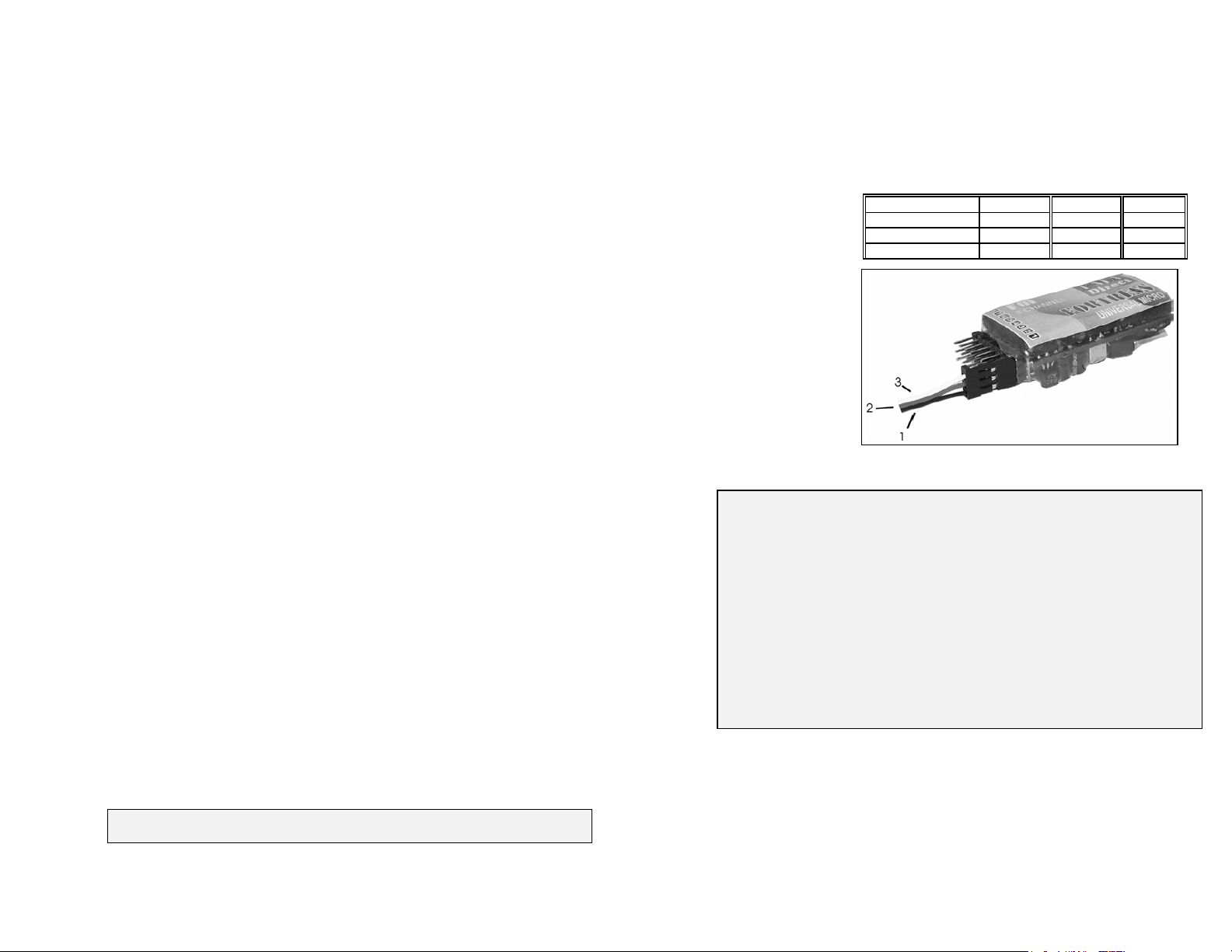
4. When hooking up servos to your receiver, use TABLE 1 and FIGURE 1 to check its
plug wire color orientation. Note: with the receiver sitting label side up, the signal lead
(marked #3 in FIGURE 1 and color coded as in TABLE 1) must match up to the pin
closest to the label side of the receiver. No damage will occur by plugging a servo in
backwards (reversing shell 180°), but the servo will not operate. Your Fortress
TABLE 1 SERVO PLUG COLOR ORIENTATION
SERVO BRAND 1 2 3
FUTABA BLK RED WHT
JR BRN RED ORG
HITEC BLK RED YLW
Figure 1
 Loading...