


Fortress Security System
Secure Wireless
Access Bridge
User Guide
www.fortresstech.com
© 2006 Fortress Technologies

Fortress Bridge
Fortress Secure Wireless Access Bridge 2.6.1
Copyright © 2006 Fortress Technologies, Inc. All rights reserved.
This document contains proprietary information protected by copyright. No part of this document may be reproduced or transmitted in any form or by any means, electronic or mechanical, without written permission of Fortress Technologies, 4023 Tampa Road, Suite 2000, Oldsmar, FL 34677, except as specified in the Product Warranty and License Terms.
FORTRESS TECHNOLOGIES, INC., MAKES NO WARRANTY OF ANY KIND WITH REGARD TO THIS MATERIAL, INCLUDING BUT NOT LIMITED TO THE IMPLIED WARRANTIES OF MERCHANTABILITY AND FITNESS FOR A PARTICULAR PURPOSE. FORTRESS TECHNOLOGIES, INC. SHALL NOT BE LIABLE FOR ERRORS CONTAINED HEREIN OR FOR INCIDENTAL OR CONSEQUENTIAL DAMAGES IN CONNECTION WITH THE FURNISHING, PERFORMANCE OR USE OF THIS MATERIAL. THE INFORMATION IN THIS DOCUMENT IS SUBJECT TO CHANGE WITHOUT NOTICE.
The Fortress Technologies and AirFortress logos and AirFortress and are registered trademarks; Multi-Factor Authentication, Unified Security Model, Wireless Link Layer Security and Three Factor Authentication (TFA) are trademarks of Fortress Technologies, Inc. The technology behind Wireless Link Layer Security™ enjoys U.S. and international patent protection under patent number 5,757,924.
Portions of this software are covered by the GNU General Public License (GPL) Copyright © 1989, 1991 Free Software Foundation, Inc,. 59 Temple Place, Suite 330, Boston, MA 02111-1307 USA.
To receive a complete machine-readable copy of the corresponding source code on CD, send $10 (to cover the costs of production and mailing) to: Fortress Technologies; 4023 Tampa Road, suite 2000; Oldsmar, FL 34677-3216. Please be sure to include a copy of your Fortress Technologies invoice and a valid “ship to” address.
This product uses the Abyss Web Server. Copyright © 2000 Moez Mahfoudh (moez@bigfoot.com). All rights reserved.
This product includes cryptographic software written by Eric Young (eay@cryptsoft.com). This product includes software written by Tim Hudson (tjh@cryptsoft.com).
Copyright © 1995-1998 Eric Young (eay@cryptsoft.com) All rights reserved.
This package is an SSL implementation written by Eric Young (eay@cryptsoft.com). The implementation was written so as to conform with Netscape’s SSL.
THIS SOFTWARE IS PROVIDED BY ERIC YOUNG ``AS IS'' AND ANY EXPRESS OR IMPLIED WARRANTIES, INCLUDING, BUT NOT LIMITED TO, THE IMPLIED WARRANTIES OF MERCHANTABILITY AND FITNESS FOR A PARTICULAR PURPOSE ARE DISCLAIMED. IN NO EVENT SHALL THE AUTHOR OR CONTRIBUTORS BE LIABLE FOR ANY DIRECT, INDIRECT, INCIDENTAL, SPECIAL, EXEMPLARY, OR CONSEQUENTIAL DAMAGES (INCLUDING, BUT NOT LIMITED TO, PROCUREMENT OF SUBSTITUTE GOODS OR SERVICES; LOSS OF USE, DATA, OR PROFITS; OR BUSINESS INTERRUPTION) HOWEVER CAUSED AND ON ANY THEORY OF LIABILITY, WHETHER IN CONTRACT, STRICT LIABILITY, OR TORT (INCLUDING NEGLIGENCE OR OTHERWISE) ARISING IN ANY WAY OUT OF THE USE OF THIS SOFTWARE, EVEN IF ADVISED OF THE POSSIBILITY OF SUCH DAMAGE.
Atheros, the Atheros logo, Atheros Driven, Driving the wireless future, Super G and Super AG are all registered trademarks of Atheros Communications. ROCm, JumpStart for Wireless, Atheros XR, Wake-on-Wireless, Wake-on-Theft, and FastFrames, are all trademarks of Atheros Communications, Inc.
This product uses Dynamic Host Control Protocol copyright 1995, 1996, 1997, 1998, 1999 by the Internet Software Consortium-DHCP. All rights reserved.
This product includes software developed by the OpenSSL Project for use in the OpenSSL Toolkit. (http://www.openssl.org/)
Copyright © 1998-2005 The OpenSSL Project. All rights reserved.THIS SOFTWARE IS PROVIDED BY THE OpenSSL PROJECT ``AS IS'' AND ANY EXPRESSED OR IMPLIED WARRANTIES, INCLUDING, BUT NOT LIMITED TO, THE IMPLIED WARRANTIES OF MERCHANTABILITY AND FITNESS FOR A PARTICULAR PURPOSE ARE
i

Fortress Bridge
DISCLAIMED. IN NO EVENT SHALL THE OpenSSL PROJECT OR ITS CONTRIBUTORS BE LIABLE FOR ANY DIRECT, INDIRECT, INCIDENTAL, SPECIAL, EXEMPLARY, OR CONSEQUENTIAL DAMAGES (INCLUDING, BUT NOT LIMITED TO, PROCUREMENT OF SUBSTITUTE GOODS OR SERVICES; LOSS OF USE, DATA, OR PROFITS; OR BUSINESS INTERRUPTION) HOWEVER CAUSED AND ON ANY THEORY OF LIABILITY, WHETHER IN CONTRACT, STRICT LIABILITY, OR TORT (INCLUDING NEGLIGENCE OR OTHERWISE) ARISING IN ANY WAY OUT OF THE USE OF THIS SOFTWARE, EVEN IF ADVISED OF THE POSSIBILITY OF SUCH DAMAGE.
This product uses Net-SNMP Copyright © 1989, 1991, 1992 by Carnegie Mellon University, Derivative Work - 1996, 1998-2000. Copyright © 1996, 1998-2000 The Regents of the University of California. All rights reserved. Copyright © 2001-2003, Cambridge Broadband Ltd. All rights reserved. Copyright © 2003 Sun Microsystems, Inc. All rights reserved. Copyright © 2001-2006, Networks Associates Technology, Inc. All rights reserved. Center of Beijing University of Posts and Telecommunications. All rights reserved.
Microsoft and Windows are registered trademarks of the Microsoft Corporation. Firefox is a trademark of the Mozilla Foundation.
All other trademarks mentioned in this document are the property of their respective owners.
FCC EMISSIONS COMPLIANCE STATEMENT
THIS EQUIPMENT HAS BEEN TESTED AND FOUND TO COMPLY WITH THE LIMITS FOR A CLASS A DIGITAL DEVICE, PURSUANT TO PART 15 OF THE FCC RULES. THESE LIMITS ARE DESIGNED TO PROVIDE REASONABLE PROTECTION AGAINST HARMFUL INTERFERENCE WHEN THE EQUIPMENT IS OPERATED IN A COMMERCIAL ENVIRONMENT. THIS EQUIPMENT GENERATES, USES, AND CAN RADIATE RADIO FREQUENCY ENERGY AND, IF NOT INSTALLED AND USED IN ACCORDANCE WITH THE INSTRUCTION MANUAL, MAY CAUSE HARMFUL INTERFERENCE TO RADIO COMMUNICATIONS. OPERATION OF THIS EQUIPMENT IN A RESIDENTIAL AREA IS LIKELY TO CAUSE HARMFUL INTERFERENCE IN WHICH CASE THE USER WILL BE REQUIRED TO CORRECT THE INTERFERENCE AT HIS OWN EXPENSE.
FCC CLASS A WARNING
MODIFYING THE EQUIPMENT WITHOUT FORTRESS AUTHORIZATION MAY RESULT IN THE EQUIPMENT NO LONGER COMPLYING WITH FCC REQUIREMENTS FOR CLASS A DIGITAL DEVICES. IN THAT EVENT, YOUR RIGHT TO USE THE EQUIPMENT MAY BE LIMITED BY FCC REGULATIONS, AND YOU MAY BE REQUIRED TO CORRECT ANY INTERFERENCE TO RADIO OR TELEVISION COMMUNICATIONS AT YOUR OWN EXPENSE.
TO COMPLY WITH FCC RF EXPOSURE COMPLIANCE REQUIREMENTS, THE ANTENNAS USED FOR THESE TRANSMITTERS MUST BE INSTALLED TO PROVIDE A SEPARATION DISTANCE OF AT LEAST 20 CM FROM ALL PERSONS AND MUST NOT BE CO-LOCATED OR OPERATED IN CONJUNCTION WITH ANY OTHER ANTENNA OR TRANSMITTER.
ii

Fortress Bridge: Table of Contents
Table of Contents
1 |
1 |
Introduction |
Fortress Secure Wireless Access Bridge . . . . . . . . . . . . . . . . . . . . .1
Management Interfaces . . . . . . . . . . . . . . . . . . . . . . . . . . . . . . . . . . . . . . . . 1
Bridge GUI . . . . . . . . . . . . . . . . . . . . . . . . . . . . . . . . . . . . . . . . . . . . . . . . . . . . . . . . . . .1
Bridge CLI . . . . . . . . . . . . . . . . . . . . . . . . . . . . . . . . . . . . . . . . . . . . . . . . . . . . . . . . . . . .2
SNMP . . . . . . . . . . . . . . . . . . . . . . . . . . . . . . . . . . . . . . . . . . . . . . . . . . . . . . . . . . . . . . .2
Network Security Overview . . . . . . . . . . . . . . . . . . . . . . . . . . . . . . . .2
The Fortress Security System . . . . . . . . . . . . . . . . . . . . . . . . . . . . .2
Multi-factor Authentication™ . . . . . . . . . . . . . . . . . . . . . . . . . . . . . . . . . . . . . 2
Strong Encryption at the MAC Layer . . . . . . . . . . . . . . . . . . . . . . . . . . . . . . 3
System Components . . . . . . . . . . . . . . . . . . . . . . . . . . . . . . . . . . . . . . . . . . 3
Operating Modes . . . . . . . . . . . . . . . . . . . . . . . . . . . . . . . . . . . . . . . . . . . . . 3
Normal Operating Mode . . . . . . . . . . . . . . . . . . . . . . . . . . . . . . . . . . . . . . . . . . . . . . . . .3
FIPS Operating Mode . . . . . . . . . . . . . . . . . . . . . . . . . . . . . . . . . . . . . . . . . . . . . . . . . . .3
Deployment Options . . . . . . . . . . . . . . . . . . . . . . . . . . . . . . . . . . . . . . . . . . . 4
This Document . . . . . . . . . . . . . . . . . . . . . . . . . . . . . . . . . . . . . . . . .5
Document Conventions . . . . . . . . . . . . . . . . . . . . . . . . . . . . . . . . . . . . . . . . 5
Related Documents . . . . . . . . . . . . . . . . . . . . . . . . . . . . . . . . . . . . . . . . . . . 5
2 |
6 |
Installation |
Introduction . . . . . . . . . . . . . . . . . . . . . . . . . . . . . . . . . . . . . . . . . . . .6
System Requirements . . . . . . . . . . . . . . . . . . . . . . . . . . . . . . . . . . . . . . . . . 6
Compatibility . . . . . . . . . . . . . . . . . . . . . . . . . . . . . . . . . . . . . . . . . . . . . . . . . 7
Preparation . . . . . . . . . . . . . . . . . . . . . . . . . . . . . . . . . . . . . . . . . . . .7
Shipped and Optional Parts . . . . . . . . . . . . . . . . . . . . . . . . . . . . . . . . . . . . . 7
Preparing the Network . . . . . . . . . . . . . . . . . . . . . . . . . . . . . . . . . . . . . . . . . 8
Port Locations . . . . . . . . . . . . . . . . . . . . . . . . . . . . . . . . . . . . . . . . . . . . . . . . 8
Safety Requirements . . . . . . . . . . . . . . . . . . . . . . . . . . . . . . . . . . . . . . . . . . 8
iii

Fortress Bridge: Table of Contents
Installation Instructions . . . . . . . . . . . . . . . . . . . . . . . . . . . . . . . . . . 11
Outdoor Installation . . . . . . . . . . . . . . . . . . . . . . . . . . . . . . . . . . . . . 11
Connecting the Bridge for Preconfiguration . . . . . . . . . . . . . . . . . . . . . . . . |
12 |
Preconfiguring the Bridge for Outdoor Operation . . . . . . . . . . . . . . . . . . . . |
12 |
Weatherizing the Bridge . . . . . . . . . . . . . . . . . . . . . . . . . . . . . . . . . . . . . . . |
16 |
Mast Mounting the Bridge . . . . . . . . . . . . . . . . . . . . . . . . . . . . . . . . . . . . . . |
18 |
Reconnecting the Bridge for Outdoor Operation . . . . . . . . . . . . . . . . . . . . |
18 |
Indoor Installation . . . . . . . . . . . . . . . . . . . . . . . . . . . . . . . . . . . . . . 19
Connecting the Bridge for Indoor Operation . . . . . . . . . . . . . . . . . . . . . . . . 19 Configuring the Bridge for Indoor Operation . . . . . . . . . . . . . . . . . . . . . . . . 20
3 |
21 |
Configuration |
The Bridge GUI . . . . . . . . . . . . . . . . . . . . . . . . . . . . . . . . . . . . . . . . 21
User Accounts . . . . . . . . . . . . . . . . . . . . . . . . . . . . . . . . . . . . . . . . . . . . . . 21
Accessing the GUI . . . . . . . . . . . . . . . . . . . . . . . . . . . . . . . . . . . . . . . . . . . 21
Logging Off . . . . . . . . . . . . . . . . . . . . . . . . . . . . . . . . . . . . . . . . . . . . . . . . . 22
LAN Settings . . . . . . . . . . . . . . . . . . . . . . . . . . . . . . . . . . . . . . . . . . 22
Spanning Tree Protocol . . . . . . . . . . . . . . . . . . . . . . . . . . . . . . . . . . . . . . . 23
WAN Port Encryption . . . . . . . . . . . . . . . . . . . . . . . . . . . . . . . . . . . . . . . . . 23
Radio Settings . . . . . . . . . . . . . . . . . . . . . . . . . . . . . . . . . . . . . . . . 24
Radio State, Band and Mode Settings . . . . . . . . . . . . . . . . . . . . . . . . . . . . 25
Radio State . . . . . . . . . . . . . . . . . . . . . . . . . . . . . . . . . . . . . . . . . . . . . . . . . . . . . . . . . . 25
Radio Band . . . . . . . . . . . . . . . . . . . . . . . . . . . . . . . . . . . . . . . . . . . . . . . . . . . . . . . . . . 25
Radio Mode . . . . . . . . . . . . . . . . . . . . . . . . . . . . . . . . . . . . . . . . . . . . . . . . . . . . . . . . . 25
Bridge Mode . . . . . . . . . . . . . . . . . . . . . . . . . . . . . . . . . . . . . . . . . . . . . . . . . . . . . . . . . 25
Radio Transmission and Reception Settings . . . . . . . . . . . . . . . . . . . . . . . 26
Channel . . . . . . . . . . . . . . . . . . . . . . . . . . . . . . . . . . . . . . . . . . . . . . . . . . . . . . . . . . . . 26
Transmit Power . . . . . . . . . . . . . . . . . . . . . . . . . . . . . . . . . . . . . . . . . . . . . . . . . . . . . . 26
Distance . . . . . . . . . . . . . . . . . . . . . . . . . . . . . . . . . . . . . . . . . . . . . . . . . . . . . . . . . . . . 27
Preamble . . . . . . . . . . . . . . . . . . . . . . . . . . . . . . . . . . . . . . . . . . . . . . . . . . . . . . . . . . . 27
Beacon Interval . . . . . . . . . . . . . . . . . . . . . . . . . . . . . . . . . . . . . . . . . . . . . . . . . . . . . . . 28
Multicasting . . . . . . . . . . . . . . . . . . . . . . . . . . . . . . . . . . . . . . . . . . . . . . . . . . . . . . . . . . 28
Received Signal Strength Indicator . . . . . . . . . . . . . . . . . . . . . . . . . . . . . . . . . . . . . . . 29
Configuring Basic Radio Settings . . . . . . . . . . . . . . . . . . . . . . . . . . . . . . . . 29
Virtual Radio Interface Settings . . . . . . . . . . . . . . . . . . . . . . . . . . . . . . . . . 29
SSID . . . . . . . . . . . . . . . . . . . . . . . . . . . . . . . . . . . . . . . . . . . . . . . . . . . . . . . . . . . . . . . |
30 |
Hide SSID and Accept G Only Options . . . . . . . . . . . . . . . . . . . . . . . . . . . . . . . . . . . . |
31 |
DTIM Period . . . . . . . . . . . . . . . . . . . . . . . . . . . . . . . . . . . . . . . . . . . . . . . . . . . . . . . . . |
31 |
RTS and Fragmentation Thresholds . . . . . . . . . . . . . . . . . . . . . . . . . . . . . . . . . . . . . . |
31 |
Security Suite and Security Suite Settings . . . . . . . . . . . . . . . . . . . . . . . . . . . . . . . . . . |
32 |
Configuring Virtual Radio Settings . . . . . . . . . . . . . . . . . . . . . . . . . . . . . . . . . . . . . . . . |
34 |
iv

Fortress Bridge: Table of Contents
802.1X Server and LAN Port Settings . . . . . . . . . . . . . . . . . . . . . . 35
802.1X Authentication Server . . . . . . . . . . . . . . . . . . . . . . . . . . . . . . . . . . . 35
LAN Port 802.1X Settings . . . . . . . . . . . . . . . . . . . . . . . . . . . . . . . . . . . . . . 36
Bridge Passwords . . . . . . . . . . . . . . . . . . . . . . . . . . . . . . . . . . . . . . 36
Security Settings . . . . . . . . . . . . . . . . . . . . . . . . . . . . . . . . . . . . . . . 37
Operating Mode . . . . . . . . . . . . . . . . . . . . . . . . . . . . . . . . . . . . . . . . . . . . . 38
Secure Shell Access . . . . . . . . . . . . . . . . . . . . . . . . . . . . . . . . . . . . . . . . . . 39
Encryption Algorithm . . . . . . . . . . . . . . . . . . . . . . . . . . . . . . . . . . . . . . . . . . 39
Re-keying Interval . . . . . . . . . . . . . . . . . . . . . . . . . . . . . . . . . . . . . . . . . . . . 40
Access ID . . . . . . . . . . . . . . . . . . . . . . . . . . . . . . . . . . . . . . . . . . . . . . . . . . 40
Non-802.1X Authentication Global and Default Settings . . . . . . . . . . . . . . 41
Enabling/Disabling Authentication Globally . . . . . . . . . . . . . . . . . . . . . . . . . . . . . . . . . |
42 |
Local Authentication Server . . . . . . . . . . . . . . . . . . . . . . . . . . . . . . . . . . . . . . . . . . . . . |
42 |
External Authentication Server . . . . . . . . . . . . . . . . . . . . . . . . . . . . . . . . . . . . . . . . . . . |
43 |
Enabling/Disabling Device Authentication . . . . . . . . . . . . . . . . . . . . . . . . . . . . . . . . . . |
44 |
Maximum Authentication Retries . . . . . . . . . . . . . . . . . . . . . . . . . . . . . . . . . . . . . . . . . |
44 |
Restart Session Login Prompt . . . . . . . . . . . . . . . . . . . . . . . . . . . . . . . . . . . . . . . . . . . |
45 |
Default User Authentication Settings . . . . . . . . . . . . . . . . . . . . . . . . . . . . . . . . . . . . . . |
46 |
Default Device Authentication Settings . . . . . . . . . . . . . . . . . . . . . . . . . . . . . . . . . . . . |
46 |
Blackout Mode . . . . . . . . . . . . . . . . . . . . . . . . . . . . . . . . . . . . . . . . 47
System Date and Time . . . . . . . . . . . . . . . . . . . . . . . . . . . . . . . . . . 48
Restoring Default Settings . . . . . . . . . . . . . . . . . . . . . . . . . . . . . . . 48
Front-Panel Operation . . . . . . . . . . . . . . . . . . . . . . . . . . . . . . . . . . 49
Mode Selection from the Front Panel . . . . . . . . . . . . . . . . . . . . . . . . . . . . . 49
Toggling the Bridge Mode Setting on Radio 2 . . . . . . . . . . . . . . . . . . . . . . . . . . . . . . . 49
Toggling the Blackout Mode setting . . . . . . . . . . . . . . . . . . . . . . . . . . . . . . . . . . . . . . . 50
Rebooting the Bridge from the Front Panel . . . . . . . . . . . . . . . . . . . . . . . . |
51 |
Restoring Defaults from the Front Panel . . . . . . . . . . . . . . . . . . . . . . . . . . |
51 |
4 |
52 |
Administration |
Device Authentication . . . . . . . . . . . . . . . . . . . . . . . . . . . . . . . . . . . 52
Maximum Device Authentication Retries . . . . . . . . . . . . . . . . . . . . . . . . . . 52
Default Device Authentication Settings . . . . . . . . . . . . . . . . . . . . . . . . . . . . 53
Individual Device Authentication Settings . . . . . . . . . . . . . . . . . . . . . . . . . . 53
Editing a Device . . . . . . . . . . . . . . . . . . . . . . . . . . . . . . . . . . . . . . . . . . . . . . . . . . . . . . 54
Deleting Devices . . . . . . . . . . . . . . . . . . . . . . . . . . . . . . . . . . . . . . . . . . . . . . . . . . . . . . 55
User Authentication . . . . . . . . . . . . . . . . . . . . . . . . . . . . . . . . . . . . 55
Maximum User Authentication Retries . . . . . . . . . . . . . . . . . . . . . . . . . . . . 56
Default User Authentication Settings . . . . . . . . . . . . . . . . . . . . . . . . . . . . . 56
Individual User Authentication Settings . . . . . . . . . . . . . . . . . . . . . . . . . . . 56
Adding a User . . . . . . . . . . . . . . . . . . . . . . . . . . . . . . . . . . . . . . . . . . . . . . . . . . . . . . . . 57
Editing a User Account . . . . . . . . . . . . . . . . . . . . . . . . . . . . . . . . . . . . . . . . . . . . . . . . . 57
Deleting a User Account . . . . . . . . . . . . . . . . . . . . . . . . . . . . . . . . . . . . . . . . . . . . . . . . 58
v

Fortress Bridge: Table of Contents
Trusted Devices . . . . . . . . . . . . . . . . . . . . . . . . . . . . . . . . . . . . . . . 59
Adding Trusted Devices . . . . . . . . . . . . . . . . . . . . . . . . . . . . . . . . . . . . . . . 59 Editing Trusted Devices . . . . . . . . . . . . . . . . . . . . . . . . . . . . . . . . . . . . . . . 60 Deleting Trusted Devices . . . . . . . . . . . . . . . . . . . . . . . . . . . . . . . . . . . . . . 61 Visitor Access through Trusted Devices . . . . . . . . . . . . . . . . . . . . . . . . . . . 61
SNMP Settings . . . . . . . . . . . . . . . . . . . . . . . . . . . . . . . . . . . . . . . . 61
Configuring SNMP . . . . . . . . . . . . . . . . . . . . . . . . . . . . . . . . . . . . . . . . . . . 62
Backing Up and Restoring . . . . . . . . . . . . . . . . . . . . . . . . . . . . . . . 62
Backing Up the Bridge Configuration . . . . . . . . . . . . . . . . . . . . . . . . . . . . . 64 Restoring from a Backup File . . . . . . . . . . . . . . . . . . . . . . . . . . . . . . . . . . . 64
Software Versions and Upgrades . . . . . . . . . . . . . . . . . . . . . . . . . . 65
Viewing Current Software Version . . . . . . . . . . . . . . . . . . . . . . . . . . . . . . . 65 Upgrading Bridge Software . . . . . . . . . . . . . . . . . . . . . . . . . . . . . . . . . . . . . 65
Rebooting the Bridge . . . . . . . . . . . . . . . . . . . . . . . . . . . . . . . . . . . |
67 |
5 |
68 |
Monitoring and Diagnostics |
Statistics . . . . . . . . . . . . . . . . . . . . . . . . . . . . . . . . . . . . . . . . . . . . . 68
Traffic Statistics . . . . . . . . . . . . . . . . . . . . . . . . . . . . . . . . . . . . . . . . . . . . . 69
Interface Statistics . . . . . . . . . . . . . . . . . . . . . . . . . . . . . . . . . . . . . . . . . . . 69
Radio Statistics . . . . . . . . . . . . . . . . . . . . . . . . . . . . . . . . . . . . . . . . . . . . . . 70
Tracking . . . . . . . . . . . . . . . . . . . . . . . . . . . . . . . . . . . . . . . . . . . . . 70
AP Associations . . . . . . . . . . . . . . . . . . . . . . . . . . . . . . . . . . . . . . . 72
View Log . . . . . . . . . . . . . . . . . . . . . . . . . . . . . . . . . . . . . . . . . . . . . 73
Diagnostics . . . . . . . . . . . . . . . . . . . . . . . . . . . . . . . . . . . . . . . . . . . 75
Pinging a Device . . . . . . . . . . . . . . . . . . . . . . . . . . . . . . . . . . . . . . . . . . . . . 75
Tracing a Packet Route . . . . . . . . . . . . . . . . . . . . . . . . . . . . . . . . . . . . . . . 75
Flushing the Host MAC Database . . . . . . . . . . . . . . . . . . . . . . . . . . . . . . . 76
Generating a Diagnostics File . . . . . . . . . . . . . . . . . . . . . . . . . . . . . . . . . . . 76
Front-Panel Indicators . . . . . . . . . . . . . . . . . . . . . . . . . . . . . . . . . . 77
System LEDs . . . . . . . . . . . . . . . . . . . . . . . . . . . . . . . . . . . . . . . . . . . . . . . 77
Radio LEDs . . . . . . . . . . . . . . . . . . . . . . . . . . . . . . . . . . . . . . . . . . . . . . . . . 78
Port LEDs . . . . . . . . . . . . . . . . . . . . . . . . . . . . . . . . . . . . . . . . . . . . . . . . . . 79
6 |
80 |
Command-Line Interface |
Introduction . . . . . . . . . . . . . . . . . . . . . . . . . . . . . . . . . . . . . . . . . . . 80
CLI Administrative Modes . . . . . . . . . . . . . . . . . . . . . . . . . . . . . . . . . . . . . . 81 Accessing the CLI through the Serial Port . . . . . . . . . . . . . . . . . . . . . . . . . 81 Accessing the CLI Remotely . . . . . . . . . . . . . . . . . . . . . . . . . . . . . . . . . . . . 81
Logging On and Off the CLI . . . . . . . . . . . . . . . . . . . . . . . . . . . . . . . . . . . . 81
vi

Fortress Bridge: Table of Contents
Getting Help in the CLI . . . . . . . . . . . . . . . . . . . . . . . . . . . . . . . . . . 82
Command Syntax . . . . . . . . . . . . . . . . . . . . . . . . . . . . . . . . . . . . . . 83
Configuration in the Bridge CLI . . . . . . . . . . . . . . . . . . . . . . . . . . . . 84
LAN Settings in the CLI . . . . . . . . . . . . . . . . . . . . . . . . . . . . . . . . . . . . . . . |
84 |
Spanning Tree Protocol in the CLI . . . . . . . . . . . . . . . . . . . . . . . . . . . . . . . |
85 |
Bridge Radio Settings in the CLI . . . . . . . . . . . . . . . . . . . . . . . . . . . . . . . . . |
85 |
Virtual Radio Interface Settings in the CLI . . . . . . . . . . . . . . . . . . . . . . . . . . . . . . . . . . |
88 |
Bridge Passwords in the CLI . . . . . . . . . . . . . . . . . . . . . . . . . . . . . . . . . . . |
90 |
Changing Bridge GUI Passwords in the CLI . . . . . . . . . . . . . . . . . . . . . . . . . . . . . . . . . |
91 |
Changing the Bridge CLI Password . . . . . . . . . . . . . . . . . . . . . . . . . . . . . . . . . . . . . . . |
91 |
Security Settings in the CLI . . . . . . . . . . . . . . . . . . . . . . . . . . . . . . . . . . . . |
91 |
Encryption Algorithm in the CLI . . . . . . . . . . . . . . . . . . . . . . . . . . . . . . . . . . . . . . . . . . 91
Re-Keying Interval in the CLI . . . . . . . . . . . . . . . . . . . . . . . . . . . . . . . . . . . . . . . . . . . . 92
Data Compression in the CLI . . . . . . . . . . . . . . . . . . . . . . . . . . . . . . . . . . . . . . . . . . . . 92
Access ID in the CLI . . . . . . . . . . . . . . . . . . . . . . . . . . . . . . . . . . . . . . . . . . . . . . . . . . . 93
Operating Mode in the CLI . . . . . . . . . . . . . . . . . . . . . . . . . . . . . . . . . . . . . . . . . . . . . . 93
WAN Port Encryption in the CLI . . . . . . . . . . . . . . . . . . . . . . . . . . . . . . . . . . . . . . . . . . 93
SSH Access to the CLI . . . . . . . . . . . . . . . . . . . . . . . . . . . . . . . . . . . . . . . . . . . . . . . . . 94
Disabling the Bridge GUI in the CLI . . . . . . . . . . . . . . . . . . . . . . . . . . . . . . . . . . . . . . . 94
Blackout Mode in the CLI . . . . . . . . . . . . . . . . . . . . . . . . . . . . . . . . . . . . . . . . . . . . . . . 94
System Date and Time in the CLI . . . . . . . . . . . . . . . . . . . . . . . . . . . . . . . . |
95 |
Restoring Default Settings in the CLI . . . . . . . . . . . . . . . . . . . . . . . . . . . . . |
95 |
Non-802.1X Authentication Settings in the CLI . . . . . . . . . . . . . . . . . . . . . |
95 |
Non-802.1X Authentication Server Settings . . . . . . . . . . . . . . . . . . . . . . . . . . . . . . . . . 95 Non-802.1X EAP Retry Interval Setting . . . . . . . . . . . . . . . . . . . . . . . . . . . . . . . . . . . . 96
802.1X Authentication Settings in the CLI . . . . . . . . . . . . . . . . . . . . . . . . . 97
802.1X Authentication Server Settings . . . . . . . . . . . . . . . . . . . . . . . . . . . . . . . . . . . . . 97 Internal LAN Switch Port 802.1X Settings . . . . . . . . . . . . . . . . . . . . . . . . . . . . . . . . . . 99
Administration in the Bridge CLI . . . . . . . . . . . . . . . . . . . . . . . . . . . 99
Trusted Devices in the CLI . . . . . . . . . . . . . . . . . . . . . . . . . . . . . . . . . . . . . 99
Adding Trusted Devices in the CLI . . . . . . . . . . . . . . . . . . . . . . . . . . . . . . . . . . . . . . . .100 Deleting Trusted Devices in the CLI . . . . . . . . . . . . . . . . . . . . . . . . . . . . . . . . . . . . . . .100
SNMP Settings in the CLI . . . . . . . . . . . . . . . . . . . . . . . . . . . . . . . . . . . . . . 100
Viewing the Software Version in the CLI . . . . . . . . . . . . . . . . . . . . . . . . . . 101 Restarting the Bridge in the CLI . . . . . . . . . . . . . . . . . . . . . . . . . . . . . . . . . 101
Monitoring and Diagnostics in the CLI . . . . . . . . . . . . . . . . . . . . . . |
101 |
Viewing a Summary Overview of the Bridge . . . . . . . . . . . . . . . . . . . . . . . |
101 |
Viewing System Uptime in the CLI . . . . . . . . . . . . . . . . . . . . . . . . . . . . . . . |
102 |
Partners Tracking in the CLI . . . . . . . . . . . . . . . . . . . . . . . . . . . . . . . . . . . . |
102 |
Host Tracking in the CLI . . . . . . . . . . . . . . . . . . . . . . . . . . . . . . . . . . . . . . . |
102 |
AP Associations in the CLI . . . . . . . . . . . . . . . . . . . . . . . . . . . . . . . . . . . . . |
103 |
Viewing the System Log in the CLI . . . . . . . . . . . . . . . . . . . . . . . . . . . . . . . |
103 |
Pinging a Device . . . . . . . . . . . . . . . . . . . . . . . . . . . . . . . . . . . . . . . . . . . . . |
104 |
Tracing a Packet Route . . . . . . . . . . . . . . . . . . . . . . . . . . . . . . . . . . . . . . . |
104 |
WLAN Wireless Extension Tools . . . . . . . . . . . . . . . . . . . . . . . . . .104
Creating a Wireless Extension Tools Script . . . . . . . . . . . . . . . . . . . . . . . . 105
vii

Fortress Bridge: Table of Contents
Secure Automatic Configuration . . . . . . . . . . . . . . . . . . . . . . . . . . .105
Preconfiguring a New Network Deployment with SAC . . . . . . . . . . . . . . . . 106
Connecting the Bridges for Preconfiguration . . . . . . . . . . . . . . . . . . . . . . . . . . . . . . . .106 Automatically Preconfiguring Network Bridges . . . . . . . . . . . . . . . . . . . . . . . . . . . . . . .106
Reconfiguring Network Settings with SAC . . . . . . . . . . . . . . . . . . . . . . . . . 109 Adding and Deleting Network Bridges with SAC . . . . . . . . . . . . . . . . . . . . 111
Adding a New SAC Network Bridge . . . . . . . . . . . . . . . . . . . . . . . . . . . . . . . . . . . . . . |
.111 |
Deleting a Bridge from a SAC Network . . . . . . . . . . . . . . . . . . . . . . . . . . . . . . . . . . . |
.113 |
7 |
114 |
Specifications |
Hardware Specifications . . . . . . . . . . . . . . . . . . . . . . . . . . . . . . . . .114
Performance . . . . . . . . . . . . . . . . . . . . . . . . . . . . . . . . . . . . . . . . . . . . . . . . 114
Physical . . . . . . . . . . . . . . . . . . . . . . . . . . . . . . . . . . . . . . . . . . . . . . . . . . 114
Environmental . . . . . . . . . . . . . . . . . . . . . . . . . . . . . . . . . . . . . . . . . . . . . . 114
Compliance . . . . . . . . . . . . . . . . . . . . . . . . . . . . . . . . . . . . . . . . . . . . . . . . . 115
Logical Interfaces . . . . . . . . . . . . . . . . . . . . . . . . . . . . . . . . . . . . . . . . . . . . 115
RJ-45-to-DB9 Console Port Adapter . . . . . . . . . . . . . . . . . . . . . . .115
8 |
117 |
Troubleshooting |
|
Index |
119 |
Glossary |
128 |
viii
Fortress Bridge: Introduction
Chapter 1
Introduction
1.1Fortress Secure Wireless Access Bridge
The Fortress Secure Wireless Access Bridge is an all-in-one network access device with the most stringent security available today built in. It can serve as a wireless bridge, a WLAN access point, and an eight-port LAN switch, while performing all the functions of a Fortress controller device: encrypting wireless traffic and providing Multi-factor Authentication for devices on the network it protects.
The rugged, compact chassis is uniquely designed, acting as an external heat sink to eliminate the need for fans and filters. The Bridge can be used indoors or outdoors with the MastMounting and Weatherizing kits that ship with every device.
The Bridge can be quickly and transparently integrated into an existing network. It can be powered with standard AC current or as an Ethernet powered device (PD) through its WAN port, which supports power over Ethernet (PoE).
Once it is installed and configured, operation is automatic, requiring no administrator intervention as it protects data transmitted on WLANs and between WLAN devices and the wired LAN.
1.1.1Management Interfaces
The Bridge can be administered through either of two native management tools: the Bridge GUI or Bridge CLI. The Bridge also supports Simple Network Management Protocol (SNMP).
1.1.1.1Bridge GUI
The Bridge’s graphical user interface is a browser-based management tool that provides administration and monitoring functions in a menuand dialog-driven format. It is accessed over the network via the Bridge’s IP address. The Bridge supports Microsoft® Internet Explorer and Mozilla Firefox™.
 1
1

Fortress Bridge: Introduction
1.1.1.2Bridge CLI
The Bridge’s command-line interface provides administration and monitoring functions via a command line. It is accessed over the network via the Bridge’s IP address or through a terminal connected directly to the Bridge’s serial Console port.
1.1.1.3SNMP
The Bridge supports versions 1 and 2 of the Simple Network Management Protocol (SNMP) Internet standard for network
management. The Fortress Management Information Base (MIB) is included on the Bridge CD and available from: www.fortresstech.com/support/products_updates.asp.
1.2Network Security Overview
Network security measures take a variety of forms; key components include:
Access controls prevent unwanted users and devices from connecting to the network. Typically some form of authentication is required, in which credentials are validated before a connection is allowed. Additionally, policy can be applied to determine what on the network the authenticated user or device can access, when, and with what permissions.
Privacy, or confidentiality, implementations prevent information from being derived from intercepted network traffic through the use of data encryption, and guard against network tampering by checking the integrity of transmitted data.
1.3The Fortress Security System
The Fortress Security System applies a combination of established and unique methodologies to both network access and data privacy.
1.3.1Multi-factor Authentication™
Fortress guards the network against illicit access with Multifactor Authentication: checking three levels of access credentials before allowing a connection.
1)Network authentication mandates that connecting devices use the correct shared identifier for the network. The Fortress Security System requires all members of a secure network to authenticate with the correct Access ID.
2)Device authentication mandates that a connecting device is individually recognized on the network through its unique device identifier. The Fortress Security System requires each device to authenticate on the secure network with the unique Device ID generated for that device.
NOTE: You cannot  configure SNMP management on a Fortress Bridge in FIPS operating mode (the
default).
2

Fortress Bridge: Introduction
3)User authentication requires the user of a connecting device to enter a recognized user name and valid credentials, a password, for example, or a digital certificate. The Fortress Security System can authenticate users locally or through existing user-authentication provisions.
1.3.2Strong Encryption at the MAC Layer
Fortress ensures network privacy at the Media Access Control (MAC) sublayer, within the Data Link Layer (Layer 2) of the Open System Interconnection (OSI) networking model. This allows a transmission’s entire contents, including the IP address and any broadcast messages, to be encrypted. Additionally, Fortress supports the FIPS-validated encryption algorithm: AES-128/192/256.
1.3.3System Components
The Fortress Security System comprises three components:
A Fortress controller device (Gateway/Controller/Bridge) provides internal network security by bridging encrypted wired or wireless communications to the wired LAN or by remotely bridging point-to-point or -multipoint LAN and WLAN connections.
The Fortress Secure Client provides device security and secure wireless connectivity for mobile devices connected to networks protected by a Fortress controller device.
Fortress Management and Policy Server (MaPS™) provides centralized management of network devices and resources, as well as rules-based access control and network, device and user authentication, by itself or integrated with back-end corporate authentication servers.
1.3.4Operating Modes
The Fortress Security System can be operated in either of two, mutually exclusive modes.
1.3.4.1Normal Operating Mode
In Normal operating mode, the Fortress Security System provides the highest available level of network security, without the additional safeguards Federally mandated for some government networks. Normal mode of operation is generally more than adequate for even the most stringent security and privacy requirements in unregulated environments.
1.3.4.2FIPS Operating Mode
In FIPS mode, the Fortress Security System complies fully with the Federal Information Processing Standards (FIPS) 140-2 standard for cryptographic products. Because of its added administrative complexities, however, FIPS mode is recommended only for networks that explicitly require FIPS compliance.
 3
3

Fortress Bridge: Introduction
1.3.5Deployment Options
The Fortress Security System is flexible and expandable.
Figure 1.1 Example Point-to-Multipoint Deployment of the Fortress Secure Wireless Access Bridge
4

Fortress Bridge: Introduction
The Bridge can provide a secure edge for a WLAN (or infrastructure-mode) deployments, as shown in Figure 1.1
1.4This Document
This user guide assumes its users have a level of expertise consistent with a professional Network Administrator.
1.4.1Document Conventions
This is a task-oriented document, and the procedures it contains are, wherever possible, self-contained and complete in themselves. Internal cross references do appear, however, rather than verbatim repetition.
Introductory matter before numbered steps will generally contain information necessary to the successful completion of the task. Descriptive matter below a stepped procedure may add to your understanding, but is not essential to the task.
Side notes throughout this document are intended to alert you to particular kinds of information, as visually indicated by their icons. Examples appear to the right of this section, in descending order of urgency.
1.4.2Related Documents
A printed Fortress Secure Wireless Access Bridge Quick Start Guide was included with your shipment.
For guidance on the Fortress Secure Client, please refer to your Fortress Secure Client user guide.
WARNING: can  cause physical injury or death to you and/or your equipment.
CAUTION: can cor-  rupt your network, your data or an intended configuration
result.
NOTE: may assist 
 you in executing the task, e.g. a convenient software feature or notice of something to
keep in mind.
5

Fortress Wireless Access Bridge: Installation
Chapter 2
Installation
2.1Introduction
The Fortress Secure Wireless Access Bridge is a full-featured Fortress controller device, providing strong data encryption and Multi-factor Authentication™, including native RADIUS authentication, to users and devices on the network it secures.
The Bridge additionally comprises three, independent network components that can be employed alone or simultaneously in any combination:
1Radio 1 is a tri-band 802.11a/b/g radio that can be configured to use either the 802.11b/g band or the 802.11a band. It can function as a wireless access point (AP), providing secure WLAN connectivity to wireless devices within range, or as a wireless bridge in a point-to-point or point-to-multipoint network.
2Radio 2 is fixed on the 802.11a band. As the higher powered of the two radios, it would normally be the first choice for the bridging function in a mixed AP/wireless bridge deployment, but it can equally function as an 802.11a AP.
3The eight RJ-45 10/100 Mbps Auto-MDIX Ethernet ports (labeled 1-8) are connectors for the Bridge’s internal LAN switch.
The Bridge is also an 802.3af power-over-Ethernet (PoE) powered device (PD), drawing power through its WAN port, when that port is connected to 802.3af power sourcing equipment (PSE).
2.1.1System Requirements
To display properly, the Bridge GUI requires a monitor resolution of at least 1024 × 768 pixels and the following (or later) browser versions:
Microsoft® Internet Explorer 6.0
Mozilla Firefox™ 1.5
NOTE: Only essen- 
 tial configuration settings, as required for basic installation, are covered in this chapter. The full complement of Bridge configuration options is described in the following chapter,
Bridge Administration.
NOTE: The internal  LAN does not support NAT (network ad-
dress translation).
6

Fortress Wireless Access Bridge: Installation
2.1.2Compatibility
The Fortress Bridge is fully compatible with Fortress Secure
Client versions 2.4 and higher.
2.2Preparation
2.2.1Shipped and Optional Parts
Included in each Fortress Bridge shipment are:
Fortress Secure Wireless Access Bridge, comprising:
one eight-port Ethernet LAN switch
one PoE Ethernet WAN port
two USB ports
one 802.11 a/b/g multi-mode radio
one 802.11a radio
two lightning arrestor modules
one universal AC-to-48V DC power adapter
AC power cord
one EBU-101-01 PoE adapter1
one RJ-45-to-DB9 adapter
(for use with a standard, straight-through CAT5 assembly)
ES520 Weatherizing Kit, including:
one front-panel cover plate
one RJ-45 connector boot assembly (six pieces)
one antenna port cap
ES520 Mast-Mounting Kit, including:
one mast mounting bracket
two 4" long, fully threaded 1/4-20 hex bolts
two 1/4" split lock washers
Optionally, you can purchase from Fortress Technologies:
5.x GHz 9dBi omnidirectional antenna with an N-type male direct connector
2.4–2.485 GHz 9dBi omnidirectional antenna with an integrated 2' antenna cable terminating in an N-type male connector
802.11a/b/g 2/2dBi tri-band rubber duck antenna with an RP-TNC connector and RP-TNC-to-N-type male connector adapter
The availability and specifications of antennas offered for purchase from Fortress Technologies are subject to change. Contact your Fortress representative for details and pricing.
1.In outdoor installations, it is mandatory that the Bridge be powered with the EBU-101-01 PoE adapter (or equivalent).
7

Fortress Wireless Access Bridge: Installation
2.2.2Preparing the Network
Any Ethernet device—including hubs, switches and access points—directly connected to the Bridge must have autonegotiation capability (and have the feature enabled), or link and/or packet loss could result. Refer to a device’s documentation to configure its negotiation options.
Secure Clients (and other Fortress Bridges) in communication with the Fortress Bridge must use the same encryption algorithm and must be assigned the same Access ID (as established in Step 5 of Section 2.4.2).
NOTE:
8

Fortress Wireless Access Bridge: Installation
General: This equipment must be installed by qualified service personnel according to the applicable installation codes. Do not locate the Bridge or antennas near power lines or power circuits. When installing an external antenna, take extreme care not to come into contact with such circuits as they can cause serious injury or death. Avoid metal ladders wherever possible. For proper installation and grounding, refer to national and/or local codes (WSNFPA 70 or, Canadian Electrical Code 54).
Indoor/Outdoor Siting: The Secure Wireless Access Bridge, with or without externally sited antennas, is intended only for installation in Environment A as defined in IEEE 802.3.af. All interconnected equipment connected to the indoor/outdoor Bridge must be contained within the same building, including the interconnected equipment's associated LAN connections.
In outdoor environments, the Secure Wireless Access Bridge shall be mounted on a wall, pole, mast or tower using the included mounting bracket. When mounted outside, the Bridge’s Front Panel Cover Plate (included) provides the necessary water and dust resistance to environmentally protect the unit. In addition, the three Front Panel Cover Plate thumbscrews must be hand-tightened (taking care not to over-tighten) to prevent the operatoraccess area (USB, Console, Ethernet ports, and power inlets) from being exposed. The Bridge should not be used outside a home, school, or other public area where the general population has access to it.
When sited inside, the unit is powered within SELV low voltage safety limits with 48VDC PoE or 48VDC external power. The included front-panel cover plate is not required for indoor installations.
Ambient Temperature: The temperature of the environment in which the Bridge operates should not exceed the maximum (122º F/50º C) or drop below the minimum
(14º F/-10º C) operating temperatures.
Powering: For external environments, the Bridge WAN (PoE-PD) port must be PoE powered with the included EBU101-01 adapter (or equivalent). The PoE adapter must derive power from the included Fortress AC-to-48V DC (70 Watt) power source to meet the safety isolation requirements defined in UL 60950. The PoE adaptor is designed for indoor use only. Never mount the power injector outside with the Secure Wireless Access Bridge.
For internal environments, the Bridge can be 1) direct powered by the universal AC-to-48V DC (70 Watt) power adapter, 2) PoE powered over the WAN port with the included EBU101-01 POE adapter (or equivalent), or 3)
 WARNING: The
  Bridge contains a 3V (7 year) lithium bat-
tery for time-keeping purposes. It is not intended to be operatoror user-replaceable. To avoid risk of personal injury (and voiding of the Bridge’s warranty), refer all hardware servicing to Fortress Technical Support. There is a risk of explosion if the battery is replaced by an incorrect type. Dispose of used batteries according to the new battery disposal instructions.
WARNING: To  avoid the risk of severe electrical shock, never remove the cover, an exterior panel, or any other part of the Bridges’s chassis. There are no user-serviceable parts inside. Refer all hardware servicing to Fortress Technical Sup-
port.
9

Fortress Wireless Access Bridge: Installation
PoE powered from a remote 802.11af (13 Watt) PoE midspan source.
Circuit Overloading: The Bridge includes a 48 V main resettable fuse specified at 1.8 A.
Lightning/Electrostatic Protection: The Bridge’s antenna ports conform to IEC1000-4-5 10 KV 8/20us waveform. The WAN port conforms to IEC-61000-4-2 8 KV waveform with 58 V additional transient protection.
Grounding: The Bridge features a rear panel grounding stud which, on Bridges with externally mounted antennas, must be connected to protective earth ground via a 20 gauge (minimum) cable, before any other physical connection is made.
The antenna/cable distribution system should be grounded (earthed) in accordance with ANSI/NFPA 70, the National Electrical Code (NEC), in particular, Section 820.93, Grounding of Outer Conductive Shield of a Coaxial Cable.
The antenna mast and Secure Wireless Access Bridge, when used outside, should be grounding per Article 810 of the NEC; of particular note is the requirement that the grounding conductor not be less than 10 AWG(Cu).
Cabling: Cables must be installed in accordance with NEC Article 725 and 800, and all requirements must be met in relationship to clearances with power lines and lighting conductors. All cabling must be category 5e per TIA/EIA- 568-B.2.
Waterproofing: The Bridge has a UL (NEMA) 3/3S/4 raintight rating. The Front-panel Cover Plate of the ES520 Weatherizing Kit includes a “Raintight” label. The Bridge is water resistant when the Weatherizing Kit (cover plate, WAN-port RJ-45 connector boot assembly, and antenna cap—included) is properly installed.
Radio Frequency: The Bridge’s internal radios conform to the FCC’s safety standard for human exposure to RF electromagnetic energy, provided that you follow these guidelines:
Do not touch or move the antennas while the unit is transmitting or receiving.
To safeguard Bridge transmitting circuitry, relocate the Bridge and its antennas only when the Bridge is powered off.
When the Bridge is transmitting, do not hold it so that the antenna is very close to or touching any exposed parts of the body, especially the face or eyes.
 WARNING: If the
  Bridge connects to outside-mounted antennas, failure to provide a low resistive earth ground can result in migration of voltage from lightning or line surges onto the premises wiring, which can cause electric shock and/or fire within the building
or structure.
10
Fortress Wireless Access Bridge: Installation
Antennas must be installed to provide a separation of at least 20 cm (7.9") from all persons and any co-located antenna or transmitter.
Regarding use in specific environments: • Do not operate near unshielded blasting caps or in an explosive environment. • Limit use in a hazardous location to the constraints imposed by the location’s safety director. • Abide by the rules of the Federal Aviation Administration for the use of wireless devices on airplanes. • Restrict the use of wireless devices in hospitals to the limits set forth by each hospital.
2.3Installation Instructions
The following instructions assume that you are installing the Fortress Bridge with the minimum number of possible changes to its default configuration:
The Fortress Bridge will operate in Normal operating mode.
Radio 1 will be used, in the 802.11g band, as a WLAN access point (AP) for wireless devices within range, and it will transmit and receive on channel 1.
Radio 2 will be used for bridging in a point-to-point or point- to-multipoint deployment of multiple Fortress Bridges, and it will transmit and receive on channel 149, with a distance setting of 1 mile.
STP (Spanning Tree Protocol) is enabled on the Bridge, and Multicast is enabled on the non-root Bridge(s).
In indoor deployments, the Bridge’s internal LAN switch will be used to connect a local area network.
Complete configuration guidelines, covering the full set of Fortress Bridge functions and options, are provided in Chapter 3, Configuration.
Procedures differ between indoor and outdoor installations. Refer to the instructions that apply to your deployment.
2.4Outdoor Installation
When installing the Fortress Bridge outdoors, you must use the Mast-Mounting Kit and the Weatherizing Kit—both included in every shipment—to mount and weatherize the Bridge.
When the Weatherizing Kit is installed, the only available connections to the Bridge are the front-panel WAN port and the rear-panel antenna ports.
Before installing the Bridge in a hard-to-reach, outdoor location, Fortress recommends connecting and preconfiguring the Bridge.
NOTE: The ES520  complies with UL60950-1 safety specifications. It has a UL (NEMA) 3/3S/4 (and IEC60529) environmental rating. The Frontpanel Cover Plate of the ES520 Weatherizing Kit includes a “Raintight”
label.
NOTE: Third par- 
 ty antennas are subject to local regulatory requirements. For outdoor installations, they must be water-
proof.
11

Fortress Wireless Access Bridge: Installation
2.4.1Connecting the Bridge for Preconfiguration
1Position the Bridge so that it operates only within its safe temperature range (14º–122º F/–10º–50º C).
2Connect a waterproof, standard 802.11a/b/g-capable antenna with an N-type male connector to antenna port 1 (ANT1).
3Connect an antenna cable with an N-type male connector between antenna port 2 (ANT2) and a high-gain omnidirectional or directional antenna. The antenna and cable must be waterproof.
4Connect the Bridge's WAN port to an external 802.3af PSE/ PoE (Power Sourcing Equipment/Power over Ethernet) source, which—if the WAN port will connect to a satellite link or a DSL or cable modem—provides an in-line connection to the necessary network device.
(Outdoor Bridge installations require a PoE source; the 48V power inlet cannot be connected when the Weatherizing Kit is installed.)
5Connect one of the Bridge’s Auto-MDIX Ethernet LAN ports (numbered 1–8) to a computer or switch on the wired LAN.
6Verify that all link/activity and power LEDs illuminate for all connected ports.
2.4.2Preconfiguring the Bridge for Outdoor Operation
The computer through which you configure the Bridge must have a direct (non-routed) connection to the Bridge’s unencrypted interface and an IP address in the same subnet (192.168.254.0) as the Controller’s default IP address.
 WARNING: To
  comply with FCC rules, antennas must be professionally installed. Improperly grounded outdoor antennas pose a particularly serious
safety hazard.
CAUTION: The  FCC requires colocated radio antennas to be at least 7.9" apart. The Bridge’s antenna connectors are only 5" apart. Avoid directly mounting two antennas to the Bridge’s rear-panel
connectors.
12

Fortress Wireless Access Bridge: Installation
1Open a browser application on a computer on your LAN and, in the browser address field, enter the Bridge’s default IP address: 192.168.254.254.
2Log on to the Bridge GUI, entering admin as both User ID and Password and then clicking Login.
(When prompted, agree to accept the security certificate.)
3From the main menu on the left choose LAN SETTINGS, and on the LAN SETTINGS screen:
In Host name, enter a descriptive name for the Fortress Bridge.
In LAN IP address, enter a network address for the Fortress Bridge’s management interface (the address to be used for all subsequent administrative access to the Bridge).
In LAN Subnet mask, enter the correct subnet mask for the Bridge’s IP address.
In Default gateway, enter the IP address of the default gateway (or router) for the network on which you are installing the Bridge.
If the WAN port is connected to a satellite link or a DSL or cable modem, select Clear for WAN Port.
Click Apply.
NOTE: The IP ad-  dress must be unique on the network.
NOTE: For infor-  mation about the Bridge’s STP and WAN Port encryption features
refer to Section 3.2.
4Click OK to clear the system dialog that instructs you to reboot, but do not reboot until Step 10 of these procedures, when you are again instructed to do so.
13
Fortress Wireless Access Bridge: Installation
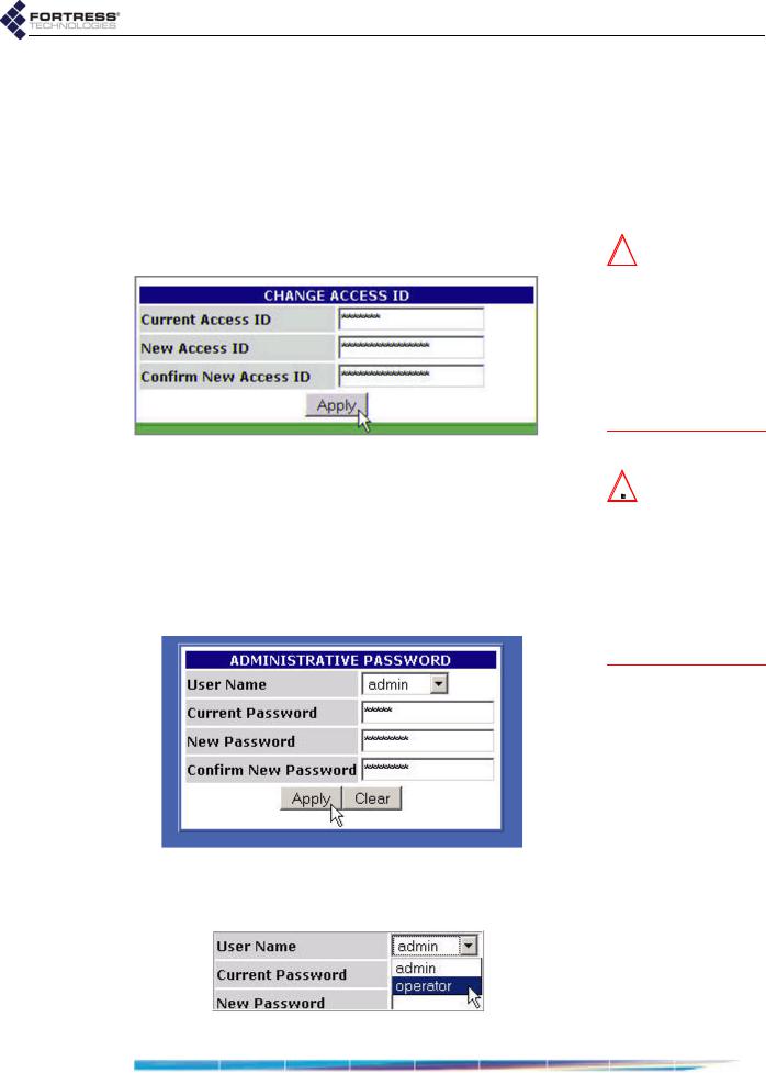
5 From the main menu, select SECURITY SETTINGS, and on the
SECURITY SETTINGS screen, in the CHANGE ACCESS ID
section:
In Current Access ID enter 16 zeros or the word default.
In New Access ID enter the 16-digit hexadecimal Access ID to be used by the Bridge and its Secure Clients.
In the Confirm New Access ID field, re-enter the new Access ID to ensure against entry errors.
detail:
CAUTION: For se-  curity reasons, the Access ID in effect on the Bridge cannot be displayed. Make a note of the new Access ID: you will need it to configure the Bridge’s Secure Clients, as well as to change the Access ID on
the Bridge.
Click Apply.
6From the main menu on the left choose BRIDGE PASSWORD, and on the BRIDGE PASSWORD screen:
Leave User Name at its default setting, admin.
In Current Password, enter the default system administrator password: admin.
In New Password, enter the password to be used to access administrative functions on the Bridge GUI.
In Confirm New Password, re-enter the new password.
Click Apply.
7On the same PASSWORD screen, repeat Step 6, except in User Name, select operator from the dropdown menu.
detail:
CAUTION: The  Bridge is not secure until you have changed the default Access ID and wireless SSIDs and reset both GUI passwords and the CLI password to a minimum of eight, mixed alphanumeric, upperand
lowercase characters.
14
Fortress Wireless Access Bridge: Installation
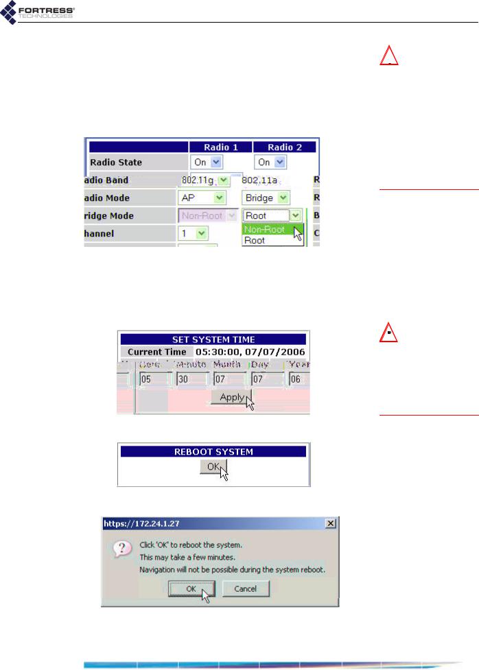
8If the Fortress Bridge is the root node in the point-to-point/ multipoint deployment, skip this step.
or
If the Fortress Bridge is the non-root node in the point-to- point/multipoint deployment, choose RADIO SETTINGS from the main menu and in Bridge Mode setting for Radio 2, choose Non-Root, and click Apply.
detail:
NOTE: If you are  deploying multiple Fortress Bridges in a
point-to-point/multi- point network they must be correctly configured for their network roles, typically with one serving as the root node and the rest configured as non-root nodes (refer to Section 2.2 for more detail).
9From the main menu on the left choose SYSTEM OPTIONS, and
on the SYSTEM OPTIONS screen, in the SET SYSTEM TIME
section, enter the correct date and time in the fields provided, using two-digit values (hh:mm MM:DD:YY), and click
Apply.
detail:
10 On the same screen, under REBOOT SYSTEM, click OK.
detail:
11 Click OK again to clear the system dialog.
12 Close your browser.
NOTE: The SYSTEM 
 OPTIONS screen features an informational timestamp under SET SYSTEM TIME. The refresh function of your browser updates this
timestamp.
15

Fortress Wireless Access Bridge: Installation
13After the Bridge reboots, change the CLI password (according to the instructions in Section 6.4.4.2) and configure unique SSIDs for the Bridge (according to the instructions in Section 3.3).
If you want to use the received signal strength indicator (RSSI) to aim the antenna of a non-root Bridge, you may want to enable it now (refer to Section 3.3.2.7).
14Disconnect the LAN, WAN and antenna ports in advance of weatherizing and mast-mounting the Bridge.
2.4.3Weatherizing the Bridge
All front-panel ports must be disconnected before you can install the Weatherizing Kit.
To install the Weatherizing Kit:
1Install the RJ-45 connector boot assembly on the end of the cable that you will be plugging into the Fortress Bridge’s WAN port, as shown in Figure 2.2:
If the RJ-45 connector is equipped with a molded plastic boot, remove it from the connector. (Some Ethernet cable connectors have a molded plastic outer casing that is not designed for removal. This style of connector is incompatible with the connector boot.)
NOTE: The Bridge  CLI provides access to some configuration settings that cannot be accessed from the Bridge GUI.
CAUTION: Do not
 assemble the connector boot without first referring to these instructions. Several assembly steps are irreversible. Incorrectly assembled connector boots are unusable, and cannot be disassembled.
Figure 2.2 Installing the RJ-45 Connector Boot Assembly
16

Fortress Wireless Access Bridge: Installation
Slide the compression nut, with the threaded opening facing toward the connector, over the connector and onto the cable.
Slide the compression bushing over the connector and onto the cable.
Slide the threaded coupler, with the flanged end facing toward the compression nut and bushing, over the connector and onto the cable.
With the smooth-side prongs on the two halves of the connector collar facing out and aligned with the RJ-45 connector’s locking tab, fit the collar around the connector so that the connector’s locking tab is compressed (the contact end of the connector extends approximately 1/2" from the collar). Fit the outer tabs on one half of the connector collar into the slots of the other, and squeeze the two halves of the connector collar together until they snap into place.
Align the primary key tab on the inner ring of the connector boot with the cable connector’s locking tab. Maintaining this alignment, fit the RJ-45 connectorcollar assembly into the boot through the boot’s threaded end and snap the collar tabs into the boot slots. Screw the connector boot securely onto the threaded coupler.
Fit the compression bushing into the flanged end of the threaded connector, and fit the compression nut over the flanges. Screw the compression nut securely onto the threaded connector until the bushing is compressed around the cable to provide a water seal.
2Attach the cover plate to the Bridge’s front panel with the plate’s three captive screws, as shown in Figure 2.3.
3If only one antenna will be attached to the Bridge, screw the antenna port cap onto the unused antenna port.
CAUTION: There  are four different possible alignments between the RJ-45 connector and the connector boot. If the boot and connector are not in the correct alignment, the RJ-45 connector will not plug into the Bridge’s
WAN port.
NOTE: Plugging
 the connector/boot into the WAN port is de-
scribed in Step 4 of Section 2.4.5.
WARNING: To  avoid the risk of severe electrical shock, do not remove the cover plate while the Fortress
Bridge is out of doors.
Figure 2.3 Attaching the Front-panel Cover Plate
17

Fortress Wireless Access Bridge: Installation
2.4.4Mast Mounting the Bridge
The Mast-Mounting Kit accommodates masts from 1.5" to 3" in diameter.
To install the Mast-Mounting Kit:
1Position the Bridge at the desired position on the mast, with the Bridge’s underside facing toward the mast and the front panel facing down, as shown in Figure 2.4
2Sandwich the mast between the underside of the Bridge and the mounting bracket, fitting the mast into the bracket’s toothed cut-outs.
3Place a split lock washer on each of the two hex bolts, sliding them down to the head of the bolt.
4Fit the bolts through the bolt holes in the mounting bracket and then into the mounting holes in the underside of the Bridge.
5Tighten the bolts securely, until the split lock washers are flattened between the bolt heads and the mounting bracket.
Figure 2.4 Attaching the Mast-Mounting Bracket and Grounding Stud
2.4.5Reconnecting the Bridge for Outdoor Operation
Review the Radio Frequency Safety Requirements (Section 2.2.4) before installing or operating Bridge radios.
1Connect the rear-panel grounding stud (shown in Figure 2.4) to protective earth ground with a 20 gauge (minimum) cable.
2Connect a waterproof, standard 802.11a/b/g-capable antenna with an N-type male connector to antenna port 1 (ANT1).
3Connect an antenna cable with a N-type male connector between antenna port 2 (ANT2) and a high-gain
 WARNING: To
  comply with FCC rules, antennas must be professionally installed. Improperly grounded outdoor antennas pose a particularly serious
safety hazard.
18

Fortress Wireless Access Bridge: Installation
omnidirectional or directional antenna. The antenna and cable must be waterproof.
4Connect the Bridge's WAN port to an external 802.3af PSE/ PoE (Power Sourcing Equipment/Power over Ethernet) source, which—if the WAN port will connect to a satellite link or a DSL or cable modem—provides an in-line connection to the necessary network device.
To plug in the RJ-45 connector with the boot assembly installed: orient the connector correctly with the WAN port, and then twist the outer ring of the connector boot clockwise until the channels in the ring align with the locking studs on the Bridge’s WAN port casing. Continue twisting the boot’s outer ring clockwise until the locking channels are fully engaged and the boot is flush with the port casing. A distinct click in the final turn of the boot’s outer ring indicates that connector and boot are securely plugged into the Bridge. (Installing the connector boot assembly is covered in Section 2.4.3.)
2.5Indoor Installation
NOTE: Third par- 
 ty antennas are subject to local regulatory requirements. For outdoor installations, they must be water-
proof.
Figure 2.5 Indoor Fortress Bridge Connections
2.5.1Connecting the Bridge for Indoor Operation
When the Fortress Bridge is installed indoors, it can be located directly on a desktop with no additional hardware, or it can be wall mounted, in any orientation—with four, #8, 3/4" wallanchored, flathead screws—through the mounting holes in the chassis’s four corners.
19

Fortress Wireless Access Bridge: Installation
1Position the Bridge so that it operates only within its safe temperature range (14º–122º F/–10º–50º C).
2Connect a standard 802.11a/b/g-capable antenna with an N-type male connector to antenna port 1 (ANT1).
3Connect an antenna cable with an N-type male connector between antenna port 2 (ANT2) and a high-gain omnidirectional or directional antenna.
4Connect the Bridge to at least one power source:
Connect the external +48V DC power supply that came with the Bridge to the front-panel +48V DC power inlet and plug the power supply into a properly rated AC power outlet with the cord provided.
and/or
Connect the Bridge’s WAN port to an external 802.3af PSE/PoE (Power Sourcing Equipment/Power over Ethernet) source. (If the WAN port will connect the Bridge to a satellite link or a DSL or cable modem, ensure the PSE/PoE source is in line with the necessary network device.)
5Connect up to eight wired LAN devices to the RJ-45 Ethernet ports (numbered 1-8).
6If the WAN port will connect the Bridge to a satellite link or a DSL or cable modem (and it was not connected in Step 4), connect the 10/100 WAN Ethernet port to the necessary network device.
7Verify that all link/activity and power LEDs illuminate for all connected ports.
2.5.2Configuring the Bridge for Indoor Operation
Configuration procedures for an indoor Bridge are no different from outdoor Bridge preconfiguration procedures. Follow steps 1 through 12, Section 2.4.2.
To access the Bridge GUI after initial configuration, use a new instance of your browser and the IP address you set in Step 3 of Section 2.4.2.
CAUTION: The  FCC requires colocated radio antennas to be at least 7.9" apart. The Bridge’s antenna connectors are only 5" apart. Avoid directly mounting two antennas to the Bridge’s rear-panel
connectors.
NOTE: When both  power supplies are connected, the external +48V power supply is automatically selected as the Bridge’s primary
power source.
20
 Loading...