

Page 1

Fortress Security System
Secure Wireless
Access Bridge
User Guide
www.fortresstech.com
© 2006 Fortress Technologies
Page 2

Page 3

Fortress Secure Wireless Access Bridge 2.6.1
Copyright © 2006 Fortress Technologies, Inc. All rights reserved.
This document contains proprietary information protected by copyright. No part of this
document may be reproduced or transmitted in any form or by any means, electronic or
mechanical, without written permission of Fortress Technologies, 4023 Tampa Road, Suite
2000, Oldsmar, FL 34677, except as specified in the Product Warranty and License Terms.
FORTRESS TECHNOLOGIES, INC., MAKES NO WARRANTY OF ANY KIND WITH
REGARD TO THIS MATERIAL, INCLUDING BUT NOT LIMITED TO THE IMPLIED
WARRANTIES OF MERCHANTABILITY AND FITNESS FOR A PARTICULAR
PURPOSE. FORTRESS TECHNOLOGIES, INC. SHALL NOT BE LIABLE FOR ERRORS
CONTAINED HEREIN OR FOR INCIDENTAL OR CONSEQUENTIAL DAMAGES IN
CONNECTION WITH THE FURNISHING, PERFORMANCE OR USE OF THIS
MATERIAL. THE INFORMATION IN THIS DOCUMENT IS SUBJECT TO CHANGE
WITHOUT NOTICE.
The Fortress Technologies and AirFortress logos and AirFortress and are registered
trademarks; Multi-Factor Authentication, Unified Security Model, Wireless Link Layer
Security and Three Factor Authentication (TFA) are trademarks of Fortress Technologies,
Inc. The technology behind Wireless Link Layer Security™ enjoys U.S. and international
patent protection under patent number 5,757,924.
Portions of this software are covered by the GNU General Public License (GPL) Copyright
© 1989, 1991 Free Software Foundation, Inc,. 59 Temple Place, Suite 330, Boston, MA
02111-1307 USA.
To receive a complete machine-readable copy of the corresponding source code on CD,
send $10 (to cover the costs of production and mailing) to: Fortress Technologies; 4023
Tampa Road, suite 2000; Oldsmar, FL 34677-3216. Please be sure to include a copy of
your Fortress Technologies invoice and a valid “ship to” address.
This product uses the Abyss Web Server. Copyright © 2000 Moez Mahfoudh
(moez@bigfoot.com). All rights reserved.
This product includes cryptographic software written by Eric Young (eay@cryptsoft.com).
This product includes software written by Tim Hudson (tjh@cryptsoft.com).
Copyright © 1995-1998 Eric Young (eay@cryptsof t.com) All rights reserved.
This package is an SSL implementation written by Eric Young (eay@cryptsoft.com). The
implementation was written so as to conform with Netscape’s SSL.
THIS SOFTWARE IS PROVIDED BY ERIC YOUNG ``AS IS'' AND ANY EXPRESS OR
IMPLIED WARRANTIES, INCLUDING, BUT NOT LIMITED TO, THE IMPLIED
WARRANTIES OF MERCHANTABILITY AND FITNESS FOR A PARTICULA R PURPOSE
ARE DISCLAIMED. IN NO EVENT SHALL THE AUTHOR OR CONTRIBUTORS BE
LIABLE FOR ANY DIRECT, INDIRECT, INCIDENTAL, SPECIAL, EXEMPLARY, OR
CONSEQUENTIAL DAMAGES (INCLUDING, BUT NOT LIMITED TO, PROCUREMENT
OF SUBSTITUTE GOODS OR SERVICES; LOSS OF USE, DATA, OR PROFITS; OR
BUSINESS INTERRUPTION) HOWEVER CAUSED AND ON ANY THEORY OF
LIABILITY, WHETHER IN CONTRACT, STRICT LIABILITY, OR TORT (INCLUDING
NEGLIGENCE OR OTHERWISE) ARISING IN ANY WAY OUT OF THE USE OF THIS
SOFTWARE, EVEN IF ADVISED OF THE POSSIBILITY OF SUCH DAMAGE.
Atheros, the Atheros logo, Atheros Driven, Driving the wireless future, Super G and Super
AG are all registered trademarks of Atheros Communications. ROCm, JumpStart for
Wireless, Atheros XR, Wake-on-Wireless, Wake-on-Theft, and FastFrames, are all
trademarks of Atheros Communications, Inc.
This product uses Dynamic Host Control Protocol copyright 1995, 1996, 1997, 1998, 1999
by the Internet Software Consortium-DHCP. All rights reserved.
This product includes software developed by the OpenSSL Project for use in the OpenSSL
Toolkit. (http://www.openssl.org/)
Copyright © 1998-2005 The OpenSSL Project. All rights reserved.THIS SOFTWARE IS
PROVIDED BY THE OpenSSL PROJECT ``AS IS'' AND ANY EXPRESSED OR IMPLIED
WARRANTIES, INCLUDING, BUT NOT LIMITED TO, THE IMPLIED WARRANTIES OF
MERCHANTABILITY AND FITNESS FOR A PARTICULAR PURPOSE ARE
Fortress Bridge
i
Page 4

DISCLAIMED. IN NO EVENT SHALL THE OpenSSL PROJECT OR ITS CONTRIBUTORS
BE LIABLE FOR ANY DIRECT, INDIRECT, INCIDENT AL, SPECIAL, EXEMPLARY, OR
CONSEQUENTIAL DAMAGES (INCLUDING, BUT NOT LIMITED TO, PROCUREMENT
OF SUBSTITUTE GOODS OR SERVICES; LOSS OF USE, DATA, OR PROFITS; OR
BUSINESS INTERRUPTION) HOWEVER CAUSED AND ON ANY THEORY OF
LIABILITY, WHETHER IN CONTRACT, STRICT LIABILITY, OR TORT (INCLUDING
NEGLIGENCE OR OTHERWISE) ARISING IN ANY WAY OUT OF THE USE OF THIS
SOFTWARE, EVEN IF ADVISED OF THE POSSIBILITY OF SUCH DAMAGE.
This product uses Net-SNMP Copyright © 1989, 1991, 1992 by Carnegie Mellon
University, Derivative Work - 1996, 1998-2000. Copyright © 1996, 1998-2000 The Regents
of the University of California. All rights reserved. Copyright © 2001-2003, Cambridge
Broadband Ltd. All rights reserved. Copyright © 2003 Sun Microsystems, Inc. All rights
reserved. Copyright © 2001-2006, Networks Associates Technology, Inc. All rights
reserved. Center of Beijing University of Posts and Telecommunications. All rights
reserved.
Microsoft and Windows are registered trademarks of the Microsoft Corporation.
Firefox is a trademark of the Mozilla Foundation.
All other trademarks mentioned in this document are the property of their respective
owners.
FCC EMISSIONS COMPLIANCE STATEMENT
THIS EQUIPMENT HAS BEEN TESTED AND FOUND TO COMPLY
WITH THE LIMITS FOR A CLASS A DIGITAL DEVICE, PURSUANT TO
PART 15 OF THE FCC RULES. THESE LIMITS ARE DESIGNED TO
PROVIDE REASONABLE PROTECTION AGAINST HARMFUL
INTERFERENCE WHEN THE EQUIPMENT IS OPERATED IN A
COMMERCIAL ENVIRONMENT. THIS EQUIPMENT GENERATES,
USES, AND CAN RADIATE RADIO FREQUENCY ENERGY AND, IF
NOT INSTALLED AND USED IN ACCORDANCE WITH THE
INSTRUCTION MANUAL, MAY CAUSE HARMFUL INTERFERENCE TO
RADIO COMMUNICATIONS. OPERATION OF THIS EQUIPMENT IN A
RESIDENTIAL AREA IS LIKELY TO CAUSE HARMFUL
INTERFERENCE IN WHICH CASE THE USER WILL BE REQUIRED TO
CORRECT THE INTERFERENCE AT HIS OWN EXPENSE.
Fortress Bridge
FCC CLASS A WARNING
MODIFYING THE EQUIPMENT WITHOUT FORTRESS
AUTHORIZATION MAY RESULT IN THE EQUIPMENT NO LONGER
COMPLYING WITH FCC REQUIREMENTS FOR CLASS A DIGITAL
DEVICES. IN THAT EVENT, YOUR RIGHT TO USE THE EQUIPMENT
MAY BE LIMITED BY FCC REGULATIONS, AND YOU MAY BE
REQUIRED TO CORRECT ANY INTERFERENCE TO RADIO OR
TELEVISION COMMUNICATIONS AT YOUR OWN EXPENSE.
TO COMPLY WITH FCC RF EXPOSURE COMPLIANCE
REQUIREMENTS, THE ANTENNAS USED FOR THESE
TRANSMITTERS MUST BE INSTALLED TO PROVIDE A SEPARATION
DISTANCE OF AT LEAST 20 CM FROM ALL PERSONS AND MUST
NOT BE CO-LOCATED OR OPERATED IN CONJUNCTION WITH ANY
OTHER ANTENNA OR TRANSMITTER.
ii
Page 5

Fortress Bridge: Table of Contents
Table of Contents
1
Introduction 1
Fortress Secure Wireless Access Bridge . . . . . . . . . . . . . . . . . . . . .1
Management Interfaces . . . . . . . . . . . . . . . . . . . . . . . . . . . . . . . . . . . . . . . .1
Bridge GUI . . . . . . . . . . . . . . . . . . . . . . . . . . . . . . . . . . . . . . . . . . . . . . . . . . . . . . . . . . .1
Bridge CLI . . . . . . . . . . . . . . . . . . . . . . . . . . . . . . . . . . . . . . . . . . . . . . . . . . . . . . . . . . . .2
SNMP . . . . . . . . . . . . . . . . . . . . . . . . . . . . . . . . . . . . . . . . . . . . . . . . . . . . . . . . . . . . . . .2
Network Security Overview . . . . . . . . . . . . . . . . . . . . . . . . . . . . . . . .2
The Fortress Security System . . . . . . . . . . . . . . . . . . . . . . . . . . . . .2
Multi-factor Authentication™ . . . . . . . . . . . . . . . . . . . . . . . . . . . . . . . . . . . . .2
Strong Encryption at the MAC Layer . . . . . . . . . . . . . . . . . . . . . . . . . . . . . .3
System Components . . . . . . . . . . . . . . . . . . . . . . . . . . . . . . . . . . . . . . . . . .3
Operating Modes . . . . . . . . . . . . . . . . . . . . . . . . . . . . . . . . . . . . . . . . . . . . .3
Normal Operating Mode . . . . . . . . . . . . . . . . . . . . . . . . . . . . . . . . . . . . . . . . . . . . . . . . .3
FIPS Operating Mode . . . . . . . . . . . . . . . . . . . . . . . . . . . . . . . . . . . . . . . . . . . . . . . . . . .3
Deployment Options . . . . . . . . . . . . . . . . . . . . . . . . . . . . . . . . . . . . . . . . . . .4
This Document . . . . . . . . . . . . . . . . . . . . . . . . . . . . . . . . . . . . . . . . .5
Document Conventions . . . . . . . . . . . . . . . . . . . . . . . . . . . . . . . . . . . . . . . . 5
Related Documents . . . . . . . . . . . . . . . . . . . . . . . . . . . . . . . . . . . . . . . . . . .5
2
Installation 6
Introduction . . . . . . . . . . . . . . . . . . . . . . . . . . . . . . . . . . . . . . . . . . . .6
System Requirements . . . . . . . . . . . . . . . . . . . . . . . . . . . . . . . . . . . . . . . . . 6
Compatibility . . . . . . . . . . . . . . . . . . . . . . . . . . . . . . . . . . . . . . . . . . . . . . . . .7
Preparation . . . . . . . . . . . . . . . . . . . . . . . . . . . . . . . . . . . . . . . . . . . .7
Shipped and Optional Parts . . . . . . . . . . . . . . . . . . . . . . . . . . . . . . . . . . . . .7
Preparing the Network . . . . . . . . . . . . . . . . . . . . . . . . . . . . . . . . . . . . . . . . .8
Port Locations . . . . . . . . . . . . . . . . . . . . . . . . . . . . . . . . . . . . . . . . . . . . . . . .8
Safety Requirements . . . . . . . . . . . . . . . . . . . . . . . . . . . . . . . . . . . . . . . . . .8
iii
Page 6

Fortress Bridge: Table of Contents
Installation Instructions . . . . . . . . . . . . . . . . . . . . . . . . . . . . . . . . . . 11
Outdoor Installation . . . . . . . . . . . . . . . . . . . . . . . . . . . . . . . . . . . . . 11
Connecting the Bridge for Preconfiguration . . . . . . . . . . . . . . . . . . . . . . . . 12
Preconfiguring the Bridge for Outdoor Operation . . . . . . . . . . . . . . . . . . . . 12
Weatherizing the Bridge . . . . . . . . . . . . . . . . . . . . . . . . . . . . . . . . . . . . . . . 16
Mast Mounting the Bridge . . . . . . . . . . . . . . . . . . . . . . . . . . . . . . . . . . . . . . 18
Reconnecting the Bridge for Outdoor Operation . . . . . . . . . . . . . . . . . . . . 18
Indoor Installation . . . . . . . . . . . . . . . . . . . . . . . . . . . . . . . . . . . . . . 19
Connecting the Bridge for Indoor Operation . . . . . . . . . . . . . . . . . . . . . . . . 19
Configuring the Bridge for Indoor Operation . . . . . . . . . . . . . . . . . . . . . . . . 20
3
Configuration 21
The Bridge GUI . . . . . . . . . . . . . . . . . . . . . . . . . . . . . . . . . . . . . . . . 21
User Accounts . . . . . . . . . . . . . . . . . . . . . . . . . . . . . . . . . . . . . . . . . . . . . . 21
Accessing the GUI . . . . . . . . . . . . . . . . . . . . . . . . . . . . . . . . . . . . . . . . . . . 21
Logging Off . . . . . . . . . . . . . . . . . . . . . . . . . . . . . . . . . . . . . . . . . . . . . . . . . 22
LAN Settings . . . . . . . . . . . . . . . . . . . . . . . . . . . . . . . . . . . . . . . . . . 22
Spanning Tree Protocol . . . . . . . . . . . . . . . . . . . . . . . . . . . . . . . . . . . . . . . 23
WAN Port Encryption . . . . . . . . . . . . . . . . . . . . . . . . . . . . . . . . . . . . . . . . . 23
Radio Settings . . . . . . . . . . . . . . . . . . . . . . . . . . . . . . . . . . . . . . . . 24
Radio State, Band and Mode Settings . . . . . . . . . . . . . . . . . . . . . . . . . . . . 25
Radio State . . . . . . . . . . . . . . . . . . . . . . . . . . . . . . . . . . . . . . . . . . . . . . . . . . . . . . . . . . 25
Radio Band . . . . . . . . . . . . . . . . . . . . . . . . . . . . . . . . . . . . . . . . . . . . . . . . . . . . . . . . . . 25
Radio Mode . . . . . . . . . . . . . . . . . . . . . . . . . . . . . . . . . . . . . . . . . . . . . . . . . . . . . . . . . 25
Bridge Mode . . . . . . . . . . . . . . . . . . . . . . . . . . . . . . . . . . . . . . . . . . . . . . . . . . . . . . . . . 25
Radio Transmission and Reception Settings . . . . . . . . . . . . . . . . . . . . . . . 26
Channel . . . . . . . . . . . . . . . . . . . . . . . . . . . . . . . . . . . . . . . . . . . . . . . . . . . . . . . . . . . . 26
Transmit Power . . . . . . . . . . . . . . . . . . . . . . . . . . . . . . . . . . . . . . . . . . . . . . . . . . . . . . 26
Distance . . . . . . . . . . . . . . . . . . . . . . . . . . . . . . . . . . . . . . . . . . . . . . . . . . . . . . . . . . . . 27
Preamble . . . . . . . . . . . . . . . . . . . . . . . . . . . . . . . . . . . . . . . . . . . . . . . . . . . . . . . . . . . 27
Beacon Interval . . . . . . . . . . . . . . . . . . . . . . . . . . . . . . . . . . . . . . . . . . . . . . . . . . . . . . . 28
Multicasting . . . . . . . . . . . . . . . . . . . . . . . . . . . . . . . . . . . . . . . . . . . . . . . . . . . . . . . . . . 28
Received Signal Strength Indicator . . . . . . . . . . . . . . . . . . . . . . . . . . . . . . . . . . . . . . . 29
Configuring Basic Radio Settings . . . . . . . . . . . . . . . . . . . . . . . . . . . . . . . . 29
Virtual Radio Interface Settings . . . . . . . . . . . . . . . . . . . . . . . . . . . . . . . . . 29
SSID . . . . . . . . . . . . . . . . . . . . . . . . . . . . . . . . . . . . . . . . . . . . . . . . . . . . . . . . . . . . . . . 30
Hide SSID and Accept G Only Options . . . . . . . . . . . . . . . . . . . . . . . . . . . . . . . . . . . . 31
DTIM Period . . . . . . . . . . . . . . . . . . . . . . . . . . . . . . . . . . . . . . . . . . . . . . . . . . . . . . . . . 31
RTS and Fragmentation Thresholds . . . . . . . . . . . . . . . . . . . . . . . . . . . . . . . . . . . . . . 31
Security Suite and Security Suite Settings . . . . . . . . . . . . . . . . . . . . . . . . . . . . . . . . . . 32
Configuring Virtual Radio Settings . . . . . . . . . . . . . . . . . . . . . . . . . . . . . . . . . . . . . . . . 34
iv
Page 7

Fortress Bridge: Table of Contents
802.1X Server and LAN Port Settings . . . . . . . . . . . . . . . . . . . . . . 35
802.1X Authentication Server . . . . . . . . . . . . . . . . . . . . . . . . . . . . . . . . . . . 35
LAN Port 802.1X Settings . . . . . . . . . . . . . . . . . . . . . . . . . . . . . . . . . . . . . . 36
Bridge Passwords . . . . . . . . . . . . . . . . . . . . . . . . . . . . . . . . . . . . . . 36
Security Settings . . . . . . . . . . . . . . . . . . . . . . . . . . . . . . . . . . . . . . . 37
Operating Mode . . . . . . . . . . . . . . . . . . . . . . . . . . . . . . . . . . . . . . . . . . . . . 38
Secure Shell Access . . . . . . . . . . . . . . . . . . . . . . . . . . . . . . . . . . . . . . . . . . 39
Encryption Algorithm . . . . . . . . . . . . . . . . . . . . . . . . . . . . . . . . . . . . . . . . . . 39
Re-keying Interval . . . . . . . . . . . . . . . . . . . . . . . . . . . . . . . . . . . . . . . . . . . . 40
Access ID . . . . . . . . . . . . . . . . . . . . . . . . . . . . . . . . . . . . . . . . . . . . . . . . . . 40
Non-802.1X Authentication Global and Default Settings . . . . . . . . . . . . . . 41
Enabling/Disabling Authentication Globally . . . . . . . . . . . . . . . . . . . . . . . . . . . . . . . . . 42
Local Authentication Server . . . . . . . . . . . . . . . . . . . . . . . . . . . . . . . . . . . . . . . . . . . . . 42
External Authentication Server . . . . . . . . . . . . . . . . . . . . . . . . . . . . . . . . . . . . . . . . . . . 43
Enabling/Disabling Device Authentication . . . . . . . . . . . . . . . . . . . . . . . . . . . . . . . . . . 44
Maximum Authentication Retries . . . . . . . . . . . . . . . . . . . . . . . . . . . . . . . . . . . . . . . . . 44
Restart Session Login Prompt . . . . . . . . . . . . . . . . . . . . . . . . . . . . . . . . . . . . . . . . . . . 45
Default User Authentication Settings . . . . . . . . . . . . . . . . . . . . . . . . . . . . . . . . . . . . . . 46
Default Device Authentication Settings . . . . . . . . . . . . . . . . . . . . . . . . . . . . . . . . . . . . 46
Blackout Mode . . . . . . . . . . . . . . . . . . . . . . . . . . . . . . . . . . . . . . . . 47
System Date and Time . . . . . . . . . . . . . . . . . . . . . . . . . . . . . . . . . . 48
Restoring Default Settings . . . . . . . . . . . . . . . . . . . . . . . . . . . . . . . 48
Front-Panel Operation . . . . . . . . . . . . . . . . . . . . . . . . . . . . . . . . . . 49
Mode Selection from the Front Panel . . . . . . . . . . . . . . . . . . . . . . . . . . . . . 49
Toggling the Bridge Mode Setting on Radio 2 . . . . . . . . . . . . . . . . . . . . . . . . . . . . . . . 49
Toggling the Blackout Mode setting . . . . . . . . . . . . . . . . . . . . . . . . . . . . . . . . . . . . . . . 50
Rebooting the Bridge from the Front Panel . . . . . . . . . . . . . . . . . . . . . . . . 51
Restoring Defaults from the Front Panel . . . . . . . . . . . . . . . . . . . . . . . . . . 51
4
Administration 52
Device Authentication . . . . . . . . . . . . . . . . . . . . . . . . . . . . . . . . . . . 52
Maximum Device Authentication Retries . . . . . . . . . . . . . . . . . . . . . . . . . . 52
Default Device Authentication Settings . . . . . . . . . . . . . . . . . . . . . . . . . . . . 53
Individual Device Authentication Settings . . . . . . . . . . . . . . . . . . . . . . . . . . 53
Editing a Device . . . . . . . . . . . . . . . . . . . . . . . . . . . . . . . . . . . . . . . . . . . . . . . . . . . . . . 54
Deleting Devices . . . . . . . . . . . . . . . . . . . . . . . . . . . . . . . . . . . . . . . . . . . . . . . . . . . . . . 55
User Authentication . . . . . . . . . . . . . . . . . . . . . . . . . . . . . . . . . . . . 55
Maximum User Authentication Retries . . . . . . . . . . . . . . . . . . . . . . . . . . . . 56
Default User Authentication Settings . . . . . . . . . . . . . . . . . . . . . . . . . . . . . 56
Individual User Authentication Settings . . . . . . . . . . . . . . . . . . . . . . . . . . . 56
Adding a User . . . . . . . . . . . . . . . . . . . . . . . . . . . . . . . . . . . . . . . . . . . . . . . . . . . . . . . . 57
Editing a User Account . . . . . . . . . . . . . . . . . . . . . . . . . . . . . . . . . . . . . . . . . . . . . . . . . 57
Deleting a User Account . . . . . . . . . . . . . . . . . . . . . . . . . . . . . . . . . . . . . . . . . . . . . . . . 58
v
Page 8

5
Fortress Bridge: Table of Contents
Trusted Devices . . . . . . . . . . . . . . . . . . . . . . . . . . . . . . . . . . . . . . . 59
Adding Trusted Devices . . . . . . . . . . . . . . . . . . . . . . . . . . . . . . . . . . . . . . . 59
Editing Trusted Devices . . . . . . . . . . . . . . . . . . . . . . . . . . . . . . . . . . . . . . . 60
Deleting Trusted Devices . . . . . . . . . . . . . . . . . . . . . . . . . . . . . . . . . . . . . . 61
Visitor Access through Trusted Devices . . . . . . . . . . . . . . . . . . . . . . . . . . . 61
SNMP Settings . . . . . . . . . . . . . . . . . . . . . . . . . . . . . . . . . . . . . . . . 61
Configuring SNMP . . . . . . . . . . . . . . . . . . . . . . . . . . . . . . . . . . . . . . . . . . . 62
Backing Up and Restoring . . . . . . . . . . . . . . . . . . . . . . . . . . . . . . . 62
Backing Up the Bridge Configuration . . . . . . . . . . . . . . . . . . . . . . . . . . . . . 64
Restoring from a Backup File . . . . . . . . . . . . . . . . . . . . . . . . . . . . . . . . . . . 64
Software Versions and Upgrades . . . . . . . . . . . . . . . . . . . . . . . . . . 65
Viewing Current Software Version . . . . . . . . . . . . . . . . . . . . . . . . . . . . . . . 65
Upgrading Bridge Software . . . . . . . . . . . . . . . . . . . . . . . . . . . . . . . . . . . . . 65
Rebooting the Bridge . . . . . . . . . . . . . . . . . . . . . . . . . . . . . . . . . . . 67
Monitoring and Diagnostics 68
Statistics . . . . . . . . . . . . . . . . . . . . . . . . . . . . . . . . . . . . . . . . . . . . . 68
Traffic Statistics . . . . . . . . . . . . . . . . . . . . . . . . . . . . . . . . . . . . . . . . . . . . . 69
Interface Statistics . . . . . . . . . . . . . . . . . . . . . . . . . . . . . . . . . . . . . . . . . . . 69
Radio Statistics . . . . . . . . . . . . . . . . . . . . . . . . . . . . . . . . . . . . . . . . . . . . . . 70
Tracking . . . . . . . . . . . . . . . . . . . . . . . . . . . . . . . . . . . . . . . . . . . . . 70
AP Associations . . . . . . . . . . . . . . . . . . . . . . . . . . . . . . . . . . . . . . . 72
View Log . . . . . . . . . . . . . . . . . . . . . . . . . . . . . . . . . . . . . . . . . . . . . 73
Diagnostics . . . . . . . . . . . . . . . . . . . . . . . . . . . . . . . . . . . . . . . . . . . 75
Pinging a Device . . . . . . . . . . . . . . . . . . . . . . . . . . . . . . . . . . . . . . . . . . . . . 75
Tracing a Packet Route . . . . . . . . . . . . . . . . . . . . . . . . . . . . . . . . . . . . . . . 75
Flushing the Host MAC Database . . . . . . . . . . . . . . . . . . . . . . . . . . . . . . . 76
Generating a Diagnostics File . . . . . . . . . . . . . . . . . . . . . . . . . . . . . . . . . . . 76
Front-Panel Indicators . . . . . . . . . . . . . . . . . . . . . . . . . . . . . . . . . . 77
System LEDs . . . . . . . . . . . . . . . . . . . . . . . . . . . . . . . . . . . . . . . . . . . . . . . 77
Radio LEDs . . . . . . . . . . . . . . . . . . . . . . . . . . . . . . . . . . . . . . . . . . . . . . . . . 78
Port LEDs . . . . . . . . . . . . . . . . . . . . . . . . . . . . . . . . . . . . . . . . . . . . . . . . . . 79
6
Command-Line Interface 80
Introduction . . . . . . . . . . . . . . . . . . . . . . . . . . . . . . . . . . . . . . . . . . . 80
CLI Administrative Modes . . . . . . . . . . . . . . . . . . . . . . . . . . . . . . . . . . . . . . 81
Accessing the CLI through the Serial Port . . . . . . . . . . . . . . . . . . . . . . . . . 81
Accessing the CLI Remotely . . . . . . . . . . . . . . . . . . . . . . . . . . . . . . . . . . . . 81
Logging On and Off the CLI . . . . . . . . . . . . . . . . . . . . . . . . . . . . . . . . . . . . 81
vi
Page 9

Fortress Bridge: Table of Contents
Getting Help in the CLI . . . . . . . . . . . . . . . . . . . . . . . . . . . . . . . . . . 82
Command Syntax . . . . . . . . . . . . . . . . . . . . . . . . . . . . . . . . . . . . . . 83
Configuration in the Bridge CLI . . . . . . . . . . . . . . . . . . . . . . . . . . . . 84
LAN Settings in the CLI . . . . . . . . . . . . . . . . . . . . . . . . . . . . . . . . . . . . . . . 84
Spanning Tree Protocol in the CLI . . . . . . . . . . . . . . . . . . . . . . . . . . . . . . . 85
Bridge Radio Settings in the CLI . . . . . . . . . . . . . . . . . . . . . . . . . . . . . . . . . 85
Virtual Radio Interface Settings in the CLI . . . . . . . . . . . . . . . . . . . . . . . . . . . . . . . . . . 88
Bridge Passwords in the CLI . . . . . . . . . . . . . . . . . . . . . . . . . . . . . . . . . . . 90
Changing Bridge GUI Passwords in the CLI . . . . . . . . . . . . . . . . . . . . . . . . . . . . . . . . . 91
Changing the Bridge CLI Password . . . . . . . . . . . . . . . . . . . . . . . . . . . . . . . . . . . . . . . 91
Security Settings in the CLI . . . . . . . . . . . . . . . . . . . . . . . . . . . . . . . . . . . . 91
Encryption Algorithm in the CLI . . . . . . . . . . . . . . . . . . . . . . . . . . . . . . . . . . . . . . . . . . 91
Re-Keying Interval in the CLI . . . . . . . . . . . . . . . . . . . . . . . . . . . . . . . . . . . . . . . . . . . . 92
Data Compression in the CLI . . . . . . . . . . . . . . . . . . . . . . . . . . . . . . . . . . . . . . . . . . . . 92
Access ID in the CLI . . . . . . . . . . . . . . . . . . . . . . . . . . . . . . . . . . . . . . . . . . . . . . . . . . . 93
Operating Mode in the CLI . . . . . . . . . . . . . . . . . . . . . . . . . . . . . . . . . . . . . . . . . . . . . . 93
WAN Port Encryption in the CLI . . . . . . . . . . . . . . . . . . . . . . . . . . . . . . . . . . . . . . . . . . 93
SSH Access to the CLI . . . . . . . . . . . . . . . . . . . . . . . . . . . . . . . . . . . . . . . . . . . . . . . . . 94
Disabling the Bridge GUI in the CLI . . . . . . . . . . . . . . . . . . . . . . . . . . . . . . . . . . . . . . . 94
Blackout Mode in the CLI . . . . . . . . . . . . . . . . . . . . . . . . . . . . . . . . . . . . . . . . . . . . . . . 94
System Date and Time in the CLI . . . . . . . . . . . . . . . . . . . . . . . . . . . . . . . . 95
Restoring Default Settings in the CLI . . . . . . . . . . . . . . . . . . . . . . . . . . . . . 95
Non-802.1X Authentication Settings in the CLI . . . . . . . . . . . . . . . . . . . . . 95
Non-802.1X Authentication Server Settings . . . . . . . . . . . . . . . . . . . . . . . . . . . . . . . . . 95
Non-802.1X EAP Retry Interval Setting . . . . . . . . . . . . . . . . . . . . . . . . . . . . . . . . . . . . 96
802.1X Authentication Settings in the CLI . . . . . . . . . . . . . . . . . . . . . . . . . 97
802.1X Authentication Server Settings . . . . . . . . . . . . . . . . . . . . . . . . . . . . . . . . . . . . . 97
Internal LAN Switch Port 802.1X Settings . . . . . . . . . . . . . . . . . . . . . . . . . . . . . . . . . . 99
Administration in the Bridge CLI . . . . . . . . . . . . . . . . . . . . . . . . . . . 99
Trusted Devices in the CLI . . . . . . . . . . . . . . . . . . . . . . . . . . . . . . . . . . . . . 99
Adding Trusted Devices in the CLI . . . . . . . . . . . . . . . . . . . . . . . . . . . . . . . . . . . . . . . .100
Deleting Trusted Devices in the CLI . . . . . . . . . . . . . . . . . . . . . . . . . . . . . . . . . . . . . . .100
SNMP Settings in the CLI . . . . . . . . . . . . . . . . . . . . . . . . . . . . . . . . . . . . . .100
Viewing the Software Version in the CLI . . . . . . . . . . . . . . . . . . . . . . . . . .101
Restarting the Bridge in the CLI . . . . . . . . . . . . . . . . . . . . . . . . . . . . . . . . .101
Monitoring and Diagnostics in the CLI . . . . . . . . . . . . . . . . . . . . . .101
Viewing a Summary Overview of the Bridge . . . . . . . . . . . . . . . . . . . . . . . 101
Viewing System Uptime in the CLI . . . . . . . . . . . . . . . . . . . . . . . . . . . . . . .1 02
Partners Tracking in the CLI . . . . . . . . . . . . . . . . . . . . . . . . . . . . . . . . . . . .102
Host Tracking in the CLI . . . . . . . . . . . . . . . . . . . . . . . . . . . . . . . . . . . . . . .102
AP Associations in the CLI . . . . . . . . . . . . . . . . . . . . . . . . . . . . . . . . . . . . .103
Viewing the System Log in the CLI . . . . . . . . . . . . . . . . . . . . . . . . . . . . . . .103
Pinging a Device . . . . . . . . . . . . . . . . . . . . . . . . . . . . . . . . . . . . . . . . . . . . .104
Tracing a Packet Route . . . . . . . . . . . . . . . . . . . . . . . . . . . . . . . . . . . . . . .104
WLAN Wireless Extension Tools . . . . . . . . . . . . . . . . . . . . . . . . . .104
Creating a Wireless Extension Tools Script . . . . . . . . . . . . . . . . . . . . . . . .105
vii
Page 10

Fortress Bridge: Table of Contents
Secure Automatic Configuration . . . . . . . . . . . . . . . . . . . . . . . . . . .105
Preconfiguring a New Network Deployment with SAC . . . . . . . . . . . . . . . .106
Connecting the Bridges for Preconfiguration . . . . . . . . . . . . . . . . . . . . . . . . . . . . . . . .106
Automatically Preconfiguring Network Bridges . . . . . . . . . . . . . . . . . . . . . . . . . . . . . . .106
Reconfiguring Network Settings with SAC . . . . . . . . . . . . . . . . . . . . . . . . .109
Adding and Deleting Network Bridges with SAC . . . . . . . . . . . . . . . . . . . .111
Adding a New SAC Network Bridge . . . . . . . . . . . . . . . . . . . . . . . . . . . . . . . . . . . . . . .111
Deleting a Bridge from a SAC Network . . . . . . . . . . . . . . . . . . . . . . . . . . . . . . . . . . . .113
7
Specifications 114
Hardware Specifications . . . . . . . . . . . . . . . . . . . . . . . . . . . . . . . . .114
Performance . . . . . . . . . . . . . . . . . . . . . . . . . . . . . . . . . . . . . . . . . . . . . . . .114
Physical . . . . . . . . . . . . . . . . . . . . . . . . . . . . . . . . . . . . . . . . . . . . . . . . . .114
Environmental . . . . . . . . . . . . . . . . . . . . . . . . . . . . . . . . . . . . . . . . . . . . . .114
Compliance . . . . . . . . . . . . . . . . . . . . . . . . . . . . . . . . . . . . . . . . . . . . . . . . .115
Logical Interfaces . . . . . . . . . . . . . . . . . . . . . . . . . . . . . . . . . . . . . . . . . . . .115
RJ-45-to-DB9 Console Port Adapter . . . . . . . . . . . . . . . . . . . . . . .115
8
Troubleshooting 117
Index 119
Glossary 128
viii
Page 11

Chapter 1 Introduction
1.1 Fortress Secure Wireless Access Bridge
The Fortress Secure Wireless Access Bridge is an all-in-one
network access device with the most stringent security
available today built in. It can serve as a wireless bridge, a
WLAN access point, and an eight-port LAN switch, while
performing all the functions of a Fortress controller device:
encrypting wireless traffic and providing Multi-factor
Authentication for devices on the network it protects.
Fortress Bridge: Introduction
The rugged, compact chassis is uniquely designed, acting as
an external heat sink to eliminate the need for fans and filters.
The Bridge can be used indoors or outdoors with the MastMounting and Weatherizing kits that ship with every device.
The Bridge can be quickly and transparently integrated into an
existing network. It can be powered with standard AC current
or as an Ethernet powered device (PD) through its WAN port,
which supports power over Ethernet (PoE).
Once it is installed and configured, operation is automatic,
requiring no administrator intervention as it protects data
transmitted on WLANs and between WLAN devices and the
wired LAN.
1.1.1 Management Interfaces
The Bridge can be administered through either of two native
management tools: the Bridge GUI or Bridge CLI. The Bridge
also supports Simple Network Management Protocol (SNMP).
1.1.1.1 Bridge GUI
The Bridge’s graphical user interface is a browser-based
management tool that provides administration and monitoring
functions in a menu- and dialog-driven format. It is accessed
over the network via the Bridge’s IP address. The Bridge
supports Microsoft® Internet Explorer and Mozilla Firefox™.
1
Page 12

1.1.1.2 Bridge CLI
The Bridge’s command-line interface provides administration
and monitoring functions via a command line. It is accessed
over the network via the Bridge’s IP address or through a
terminal connected directly to the Bridge’s serial
1.1.1.3 SNMP
The Bridge supports versions 1 and 2 of the Simple Network
Management Protocol (SNMP) Internet standard for network
management. The Fortress Management Information Base
(MIB) is included on the Bridge CD and available from:
www.fortresstech.com/support/products_updates.asp
1.2 Network Security Overview
Network security measures take a variety of forms; key
components include:
Access controls prevent unwanted users and devices from
connecting to the network. Typically some form of
authentication is required, in which credentials are
validated before a connection is allowed. Additionally,
policy can be applied to determine what on the network the
authenticated user or device can access, when, and with
what permissions.
Console port.
.
Fortress Bridge: Introduction
NOTE: You cannot
configure SNMP
management on a For-
tress Bridge in
erating mode (the
default).
FIPS op-
Privacy, or confidentiality, implementations prevent
information from being derived from intercepted network
traffic through the use of data encryption, and guard
against network tampering by checking the integrity of
transmitted data.
1.3 The Fortress Security System
The Fortress Security System applies a combination of
established and unique methodologies to both network access
and data privacy.
1.3.1 Multi-factor Authentication™
Fortress guards the network against illicit access with Multifactor Authentication: checking three levels of access
credentials before allowing a connection.
1) Network authentication mandates that connecting devices
use the correct shared identifier for the network. The Fortress Security System requires all members of a secure
network to authenticate with the correct Access ID.
2) Device authentication mandates that a connecting device is
individually recognized on the network through its unique
device identifier. The Fortress Security System requires
each device to authenticate on the secure network with the
unique Device ID generated for that device.
2
Page 13

3) User authentication requires the user of a connecting
device to enter a recognized user name and valid credentials, a password, for example, or a digital certificate. The
Fortress Security System can authenticate users locally or
through existing user-authentication provisions.
1.3.2 Strong Encryption at the MAC Layer
Fortress ensures network privacy at the Media Access Control
(MAC) sublayer, within the Data Link Layer (Layer 2) of the
Open System Interconnection (OSI) networking model. This
allows a transmission’s entire contents, including the IP
address and any broadcast messages, to be encrypted.
Additionally, Fortress supports the FIPS-validated encryption
algorithm: AES-128/192/256.
1.3.3 System Components
The Fortress Security System comprises three components:
A Fortress controller device (Gateway/Controller/Bridge)
provides internal network security by bridging encrypted
wired or wireless communications to the wired LAN or by
remotely bridging point-to-point or -multipoint LAN and
WLAN connections.
Fortress Bridge: Introduction
The Fortress Secure Client provides device security and
secure wireless connectivity for mobile devices connected
to networks protected by a Fortress controller device.
Fortress Management and Policy Server (MaPS™)
provides centralized management of network devices and
resources, as well as rules-based access control and
network, device and user authentication, by itself or
integrated with back-end corporate authentication servers.
1.3.4 Operating Modes
The Fortress Security System can be operated in either of two,
mutually exclusive modes.
1.3.4.1 Normal Operating Mode
In Normal operating mode, the Fortress Security System
provides the highest available level of network security, without
the additional safeguards Federally mandated for some
government networks. Normal mode of operation is generally
more than adequate for even the most stringent security and
privacy requirements in unregulated environments.
1.3.4.2 FIPS Operating Mode
In FIPS mode, the Fortress Security System complies fully with
the Federal Information Processing Standards (FIPS) 140-2
standard for cryptographic products. Because of its added
administrative complexities, however, FIPS mode is
recommended only for networks that explicitly require FIPS
compliance.
3
Page 14

1.3.5 Deployment Options
The Fortress Security System is flexible and expandable.
Fortress Bridge: Introduction
Figure 1.1 Example Point-to-Multipoint Deployment of the Fortress Secure Wireless Access Bridge
4
Page 15

The Bridge can provide a secure edge for a WLAN (or
infrastructure-mode) deployments, as shown in Figure 1.1
Fortress Bridge: Introduction
1.4 This Document
This user guide assumes its users have a level of expertise
consistent with a professional Network Administrator.
1.4.1 Document Conventions
This is a task-oriented document, and the procedures it
contains are, wherever possible, self-contained and complete
in themselves. Internal cross references do appear, however,
rather than verbatim repetition.
Introductory matter before numbered steps will generally
contain information necessary to the successful completion of
the task. Descriptive matter below a stepped procedure may
add to your understanding, but is not essential to the task.
Side notes throughout this document are intended to alert you
to particular kinds of information, as visually indicated by their
icons. Examples appear to the right of this section, in
descending order of urgency.
1.4.2 Related Documents
A printed Fortress Secure Wireless Access Bridge Quick Start
Guide was included with your shipment.
For guidance on the Fortress Secure Client, please refer to
your Fortress Secure Client user guide.
WARNING: can
cause physical in-
jury or death to you
and/or your equipment.
CAUTION: can cor-
rupt your net-
work, your data o r an
intended configuration
result.
NOTE: may assist
you in executing
the task, e.g. a conve-
nient software feature or
notice of something to
keep in mind.
5
Page 16

Chapter 2 Installation
2.1 Introduction
Fortress Wireless Access Bridge: Installation
The Fortress Secure Wireless Access Bridge is a full-featured
Fortress controller device, providing strong data encryption and
Multi-factor Authentication™, including native RADIUS
authentication, to users and devices on the network it secures.
The Bridge additionally comprises three, independent network
components that can be employed alone or simultaneously in
any combination:
1 Radio 1 is a tri-band 802.11a/b/g radio that can be
configured to use either the 802.11b/g band or the 802.11a
band. It can function as a wireless access point (AP),
providing secure WLAN connectivity to wireless devices
within range, or as a wireless bridge in a point-to-point or
point-to-multipoint network.
2 Radio 2 is fixed on the 802.11a band. As the higher
powered of the two radios, it would normally be the first
choice for the bridging function in a mixed AP/wireless
bridge deployment, but it can equally function as an
802.11a AP.
3 The eight RJ-45 10/100 Mbps Auto-MDIX Ethernet ports
(labeled
1-8) are connectors for the Bridge’s internal LAN
switch.
The Bridge is also an 802.3af power-over-Ethernet (PoE)
powered device (PD), drawing power through its WAN port,
when that port is connected to 802.3af power sourcing
equipment (PSE).
NOTE: Only essen-
tial configuration
settings, as required for
basic installation, are
covered in this chapter.
The full complement of
Bridge configuration
options is described in
the following chapter,
Bridge Administration.
NOTE: The internal
LAN does not sup-
port NAT (network ad-
dress translation).
2.1.1 System Requirements
To display properly, the Bridge GUI requires a monitor
resolution of at least 1024 × 768 pixels and the following (or
later) browser versions:
Microsoft® Internet Explorer 6.0
Mozilla Firefox™ 1.5
6
Page 17

2.1.2 Compatibility
The Fortress Bridge is fully compatible with Fortress Secure
Client versions 2.4 and higher.
2.2 Preparation
2.2.1 Shipped and Optional Parts
Included in each Fortress Bridge shipment are:
Fortress Secure Wireless Access Bridge, comprising:
one eight-port Ethernet LAN switch
one PoE Ethernet WAN port
two USB ports
one 802.11 a/b/g multi-mode radio
one 802.11a radio
two lightning arrestor modules
one universal AC-to-48V DC power adapter
AC power cord
one EBU-101-01 PoE adapter
one RJ-45-to-DB9 adapter
(for use with a standard, straight-through CAT5 assembly)
ES520 Weatherizing Kit, including:
one front-panel cover plate
one RJ-45 connector boot assembly (six pieces)
one antenna port cap
ES520 Mast-Mounting Kit, including:
one mast mounting bracket
two 4" long, fully threaded 1/4-20 hex bolts
two 1/4" split lock washers
1
Fortress Wireless Access Bridge: Installation
Optionally, you can purchase from Fortress Technologies:
5.x GHz 9dBi omnidirectional antenna with an N-type male
direct connector
2.4–2.485 GHz 9dBi omnidirectional antenna with an
integrated 2' antenna cable terminating in an N-type male
connector
802.11a/b/g 2/2dBi tri-band rubber duck antenna with an
RP-TNC connector and RP-TNC-to-N-type male connector
adapter
The availability and specifications of antennas offered for
purchase from Fortress Technologies are subject to change.
Contact your Fortress representative for details and pricing.
1. In outdoor installations, it is mandatory that the Bridge be powered with the
EBU-101-01 PoE adapter (or equivalent).
7
Page 18

2.2.2 Preparing the Network
Any Ethernet device—including hubs, switches and access
points—directly connected to the Bridge must have autonegotiation capability (and have the feature enabled), or link
and/or packet loss could result. Refer to a device’s
documentation to configure its negotiation options.
Secure Clients (and other Fortress Bridges) in communication
with the Fortress Bridge must use the same encryption
algorithm and must be assigned the same Access ID (as
established in Step 5 of Section 2.4.2).
Fortress Wireless Access Bridge: Installation
If you are deploying multiple Fortress Bridges in a potopo or reto-multipo network hey should be correctly
configured for their network roles. Typically, one Bridge serves
as the roo node in the network and the rest are configured as
non-roo nodes.
A Fortress Bridge in root mode does not initiate connections
with other Fortress Bridges, while Bridges in non-roo mode do
initiate connections with other Fortress Bridges—either directly
with a roo Bridge or with another non-roo Bridge. (The Bridge
Mode is established in Step 8 of Section 2.4.2.)
2.2.3 Port Locations
The Bridge’s dual antenna ports and grounding stud are
located on the back panel. The rest of the Bridge’s rerts are
located on the fro panel, shown below.
NOTE: In
/multire
deployments, the trans-
mission and reception
settings on all of the ra-
ios used to form the
network must match.
Figure 2.1 Fortress Bridge Port Locations
8
Page 19

Fortress Wireless Access Bridge: Installation
General: This equipment must be installed by qualified
service personnel according to the applicable installation
codes. Do not locate the Bridge or antennas near power
lines or power circuits. When installing an external antenna,
take extreme care not to come into contact with such
circuits as they can cause serious injury or death. Avoid
metal ladders wherever possible. For proper installation
and grounding, refer to national and/or local codes
(WSNFPA 70 or, Canadian Electrical Code 54).
Indoor/Outdoor Siting: The Secure Wireless Access Bridge,
with or without externally sited antennas, is intended only
for installation in Environment A as defined in IEEE
802.3.af. All interconnected equipment connected to the
indoor/outdoor Bridge must be contained within the same
building, including the interconnected equipment's
associated LAN connections.
In outdoor environments, the Secure Wireless Access
Bridge shall be mounted on a wall, pole, mast or tower
using the included mounting bracket. When mounted
outside, the Bridge’s Front Panel Cover Plate (included)
provides the necessary water and dust resistance to
environmentally protect the unit. In addition, the three Front
Panel Cover Plate thumbscrews must be hand-tightened
(taking care not to over-tighten) to prevent the operatoraccess area (USB, Console, Ethernet ports, and power
inlets) from being exposed. The Bridge should not be used
outside a home, school, or other public area where the
general population has access to it.
WARNING: The
Bridge contains a
3V (7 year) lithium bat-
tery for time-keeping
purposes. It is not in-
tended to be operator-
or user-replaceable. To
avoid risk of personal
injury (and voiding of
the Bridge’s warranty),
refer all hardware ser-
vicing to Fortress Tech-
nical Support. There is a
risk of explosion if the battery is replaced by an incorrect type. Dispose of
used batteries according
to the new battery dis-
posal instructions.
When sited inside, the unit is powered within SELV low
voltage safety limits with 48VDC PoE or 48VDC external
power. The included front-panel cover plate is not required
for indoor installations.
Ambient Temperature: The temperature of the environment
in which the Bridge operates should not exceed the
maximum (
(
14º F/-10º C) operating temperatures.
Powering: For external environments, the Bridge WAN
(PoE-PD) port
EBU101-01 adapter (or equivalent). The PoE adapter
122º F/50º C) or drop below the minimum
must be PoE powered with the included
must
derive power from the included Fortress AC-to-48V DC (70
Watt) power source to meet the safety isolation
requirements defined in UL 60950. The PoE adaptor is
designed for indoor use only. Never mount the power
injector outside with the Secure Wireless Access Bridge.
For internal environments, the Bridge can be 1) direct
powered by the universal AC-to-48V DC (70 Watt) power
adapter, 2) PoE powered over the WAN port with the
included EBU101-01 POE adapter (or equivalent), or 3)
WARNING: To
avoid the risk of
severe electrical shock,
never remove the cov-
er, an exterior panel, or
any other part of the
Bridges’s chassis. There
are no user-serviceable
parts inside. Refer all
hardware servicing to
Fortress Technical Sup-
port.
9
Page 20

Fortress Wireless Access Bridge: Installation
PoE powered from a remote 802.11af (13 Watt) PoE
midspan source.
Circuit Overloading: The Bridge includes a 48 V main
resettable fuse specified at 1.8 A.
Lightning/Electrostatic Protection: The Bridge’s antenna
ports conform to IEC1000-4-5 10 KV 8/20us waveform. The
WAN port conforms to IEC-61000-4-2 8 KV waveform with
58 V additional transient protection.
Grounding: The Bridge features a rear panel grounding
stud which, on Bridges with externally mounted antennas,
must be connected to protective earth ground via a 20
gauge (minimum) cable, before any other physical
connection is made.
The antenna/cable distribution system should be grounded
(earthed) in accordance with ANSI/NFPA 70, the National
Electrical Code (NEC), in particular, Section 820.93,
Grounding of Outer Conductive Shield of a Coaxial Cable.
The antenna mast and Secure Wireless Access Bridge,
when used outside, should be grounding per Article 810 of
the NEC; of particular note is the requirement that the
grounding conductor not be less than 10 AWG(Cu).
Cabling: Cables must be installed in accordance with NEC
Article 725 and 800, and all requirements must be met in
relationship to clearances with power lines and lighting
conductors. All cabling must be category 5e per TIA/EIA568-B.2.
Waterproofing: The Bridge has a UL (NEMA) 3/3S/4 raintight
rating. The Front-panel Cover Plate of the ES520
Weatherizing Kit includes a “Raintight” label. The Bridge is
water resistant when the Weatherizing Kit (cover plate,
WAN-port RJ-45 connector boot assembly, and antenna
cap—included) is properly installed.
Radio Frequency: The Bridge’s internal radios conform to
the FCC’s safety standard for human exposure to RF
electromagnetic energy, provided that you follow these
guidelines:
Do not touch or move the antennas while the unit is
transmitting or receiving.
To safeguard Bridge transmitting circuitry, relocate the
Bridge and its antennas only when the Bridge is
powered off.
When the Bridge is transmitting, do not hold it so that
the antenna is very close to or touching any exposed
parts of the body, especially the face or eyes.
WARNING: If the
Bridge connects to
outside-mounted anten-
nas, failure to provide a
low resistive earth
ground can result in mi-
gration of voltage from
lightning or line surges
onto the premises wir-
ing, which can cause
electric shock and/or
fire within the building
or structure.
10
Page 21

Fortress Wireless Access Bridge: Installation
Antennas must be installed to provide a separation of at
least 20 cm (7.9") from all persons and any co-located
antenna or transmitter.
Regarding use in specific environments:
operate near unshielded blasting caps or in an
explosive environment.
•
Limit use in a hazardous
location to the constraints imposed by the location’s
•
safety director.
Abide by the rules of the Federal
Aviation Administration for the use of wireless devices
on airplanes.
•
Restrict the use of wireless devices in
hospitals to the limits set forth by each hospital.
2.3 Installation Instructions
The following instructions assume that you are installing the
Fortress Bridge with the minimum number of possible changes
to its default configuration:
The Fortress Bridge will operate in Normal operating mode.
Radio 1 will be used, in the 802.11g band, as a WLAN
access point (AP) for wireless devices within range, and it
will transmit and receive on channel 1.
Radio 2 will be used for bridging in a point-to-point or point-
to-multipoint deployment of multiple Fortress Bridges, and it
will transmit and receive on channel 149, with a distance
setting of 1 mile.
•
Do not
NOTE: The ES520
complies with
UL60950-1 safe ty s peci -
fications. It has a UL
(NEMA) 3/3S/4 (and
IEC60529) environmen-
tal rating. The Front-
panel Cover Plate of the
ES520 Weatherizing Kit
includes a “Raintight”
label.
STP (Spanning Tree Protocol) is enabled on the Bridge,
and Multicast is enabled on the non-root Bridge(s).
In indoor deployments, the Bridge’ s internal LAN switch will
be used to connect a local area network.
Complete configuration guidelines, covering the full set of
Fortress Bridge functions and options, are provided in Chapter
3, Configuration.
Procedures differ between indoor and outdoor installations.
Refer to the instructions that apply to your deployment.
2.4 Outdoor Installation
When installing the Fortress Bridge out doors, you must use the
Mast-Mounting Kit and the Weatherizing Kit—both included in
every shipment—to mount and weatherize the Bridge.
When the Weatherizing Kit is installed, the only available
connections to the Bridge are the front-panel WAN port and the
rear-panel antenna ports.
Before installing the Bridge in a hard-to-reach, outdoor
location, Fortress recommends connecting and preconfiguring
the Bridge.
NOTE: Third par-
ty antennas are
subject to local regulato-
ry requirements. For
outdoor installations,
they must be water-
proof.
11
Page 22
Fortress Wireless Access Bridge: Installation
2.4.1 Connecting the Bridge for Preconfiguration
1 Position the Bridge so that it operates only within its safe
temperature range (14º–122º F/
2 Connect a waterproof, standard 802.11a/b/g-capable
antenna with an N-type male connector to antenna port 1
(
ANT1).
3 Connect an antenna cable with an N-type male connector
between antenna port 2 (
ANT2) and a high-gain
omnidirectional or directional antenna. The antenna and
cable must be waterproof.
4 Connect the Bridge's WAN port to an external 802.3af PSE/
PoE (Power Sourcing Equipment/Power over Ethernet)
source, which—if the WAN port will connect to a satellite
link or a DSL or cable modem—provides an in-line
connection to the necessary network device.
(Outdoor Bridge installations require a PoE source; the 48V
power inlet cannot be connected when the Weath erizing Kit
is installed.)
5 Connect one of the Bridge’s Auto-MDIX Ethernet LAN ports
(numbered
6 Verify that all link/activity and power LEDs illuminate for all
1–8) to a computer or switch on the wired LAN.
connected ports.
–
10º–50º C).
WARNING: To
comply with FCC
rules, antennas must be
professionally installed.
Improperly grounded
outdoor antennas pose a
particularly serious
safety hazard.
CAUTION: The
FCC requires co-
located radio antennas
to be at least 7.9" apart.
The Bridge’s antenna
connectors are only 5"
apart. Avoid directly
mounting two antennas to
the Bridge’s rear-panel
connectors.
2.4.2 Preconfiguring the Bridge for Outdoor Operation
The computer through which you configure the Bridge must
have a direct (non-routed) connection to the Bridge’s
unencrypted interface and an IP address in the same subnet
(192.168.254.0) as the Controller’s default IP address.
12
Page 23
Fortress Wireless Access Bridge: Installation
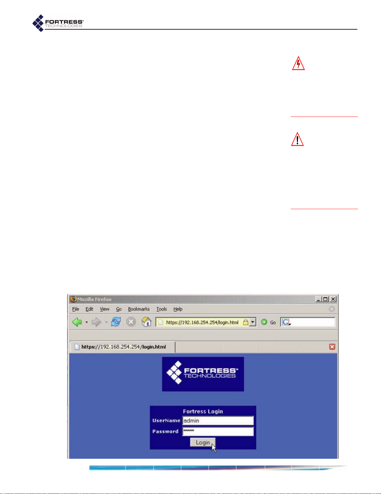
1 Open a browser application on a computer on your LAN
and, in the browser address field, enter the Bridge’s def ault
IP address:
2 Log on to the Bridge GUI, entering admin as both User ID
and Password and then clicking
192.168.254.254.
Login.
(When prompted, agree to accept the security certificate.)
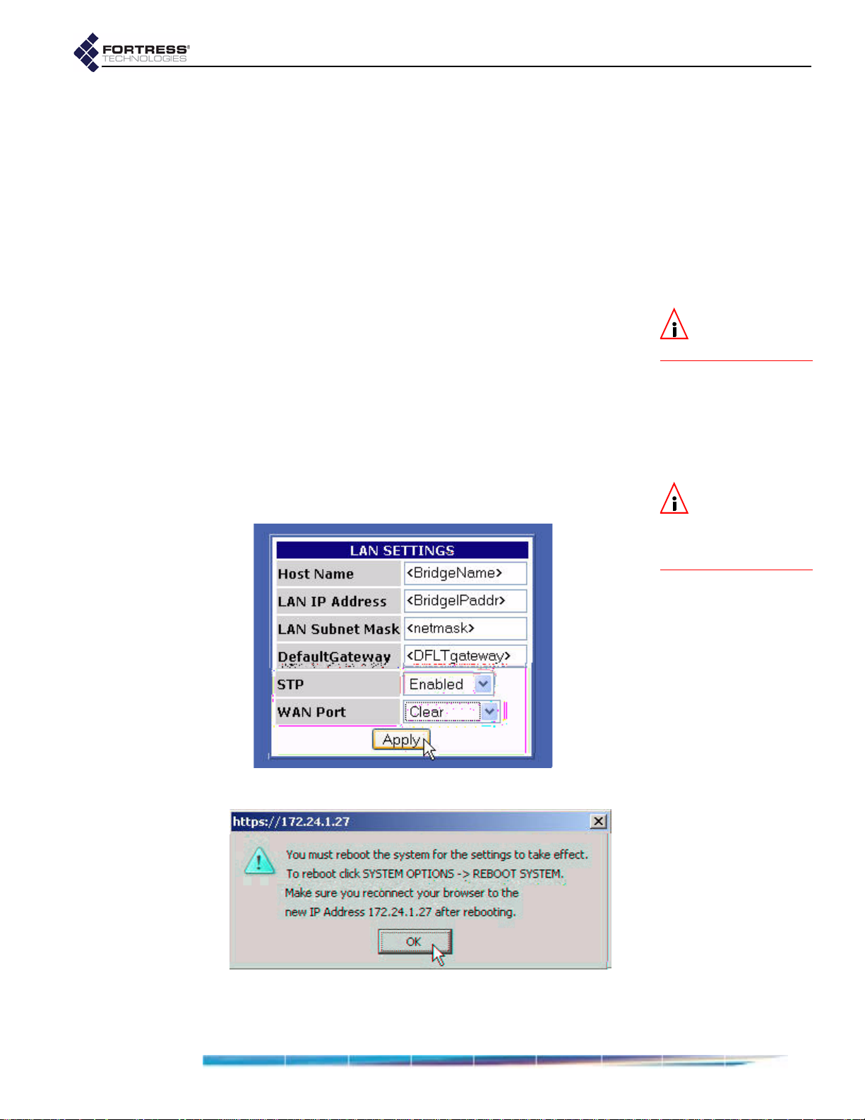
3 From the main menu on the left choose LAN SETTINGS, and
on the
In Host name, enter a descriptive name for the Fortress
LAN SETTINGS screen:
Bridge.
In LAN IP address, enter a network address for the
Fortress Bridge’s management interface (the address
to be used for all subsequent administrative access to
the Bridge).
In LAN Subnet mask, enter the correct subnet mask for
the Bridge’s IP address.
In Default gateway, enter the IP address of the default
gateway (or router) for the network on which you are
installing the Bridge.
If the WAN port is connected to a satellite link or a DSL
or cable modem, select
Clear for WAN Port.
NOTE: The IP ad-
dress must be
unique on the network.
NOTE: For infor-
mation about the
Bridge’s
Port encryption features
STP and WAN
refer to Section 3.2.
Apply.
Click
4 Click OK to clear the system dialog that instructs you to
reboot, but do not reboot until S tep 10 of these procedures,
when you are again instructed to do so.
13
Page 24
detail:
Fortress Wireless Access Bridge: Installation
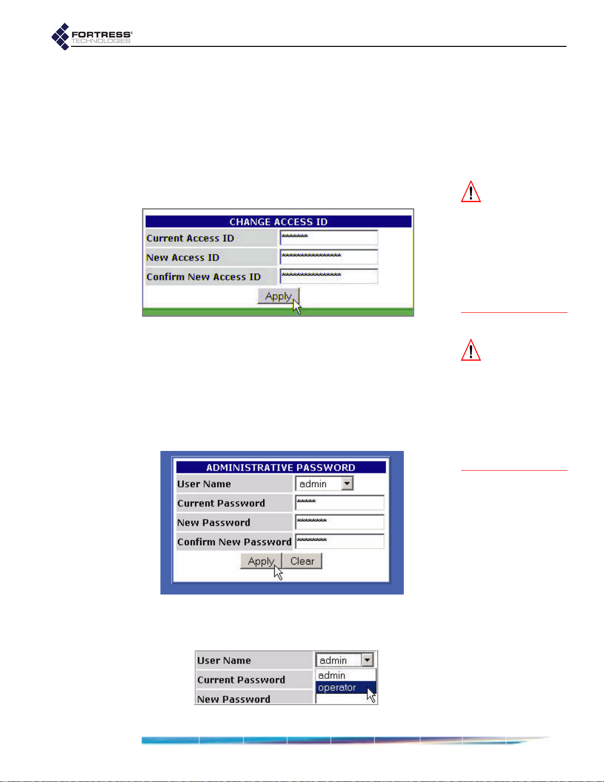
5 From the main menu, select SECURITY SETTINGS, and on the
SECURITY SETTINGS screen, in the CHANGE ACCESS ID
section:
In Current Access ID enter 16 zeros or the word
default.
In New Access ID enter the 16-digit hexadecimal
Access ID to be used by the Bridge and its Secure
Clients.
In the Confirm New Access ID field, re-enter the new
Access ID to ensure against entry errors.
CAUTION: For se-
curity reasons, the
Access ID in effect on
the Bridge cannot be
displayed. Make a note of
the new Access ID: you
will need it to configure
the Bridge’s Secure Cli-
ents, as well as to
change the Access ID on
the Bridge.
Apply.
Click
6 From the main menu on the left choose BRIDGE PASSWORD,
and on the
Leave User Name at its default setting, admin.
In Current Password, enter the default system
administrator password:
In New Password, enter the password to be used to
BRIDGE PASSWORD screen:
admin.
access administrative functions on the Bridge GUI.
In Confirm New Password, re-enter the new password.
Apply.
Click
7 On the same PASSWORD screen, repeat Step 6, except in
User Name, select
operator from the dropdown menu.
CAUTION: The
Bridge is not se-
cure until you have
changed the default Ac-
cess ID and wireless
SSIDs and reset both
GUI passwords and the
CLI password to a mini-
mum of eight, mixed al-
phanumeric, upper- and
lowercase characters.
detail:
14
Page 25
Fortress Wireless Access Bridge: Installation
detail:
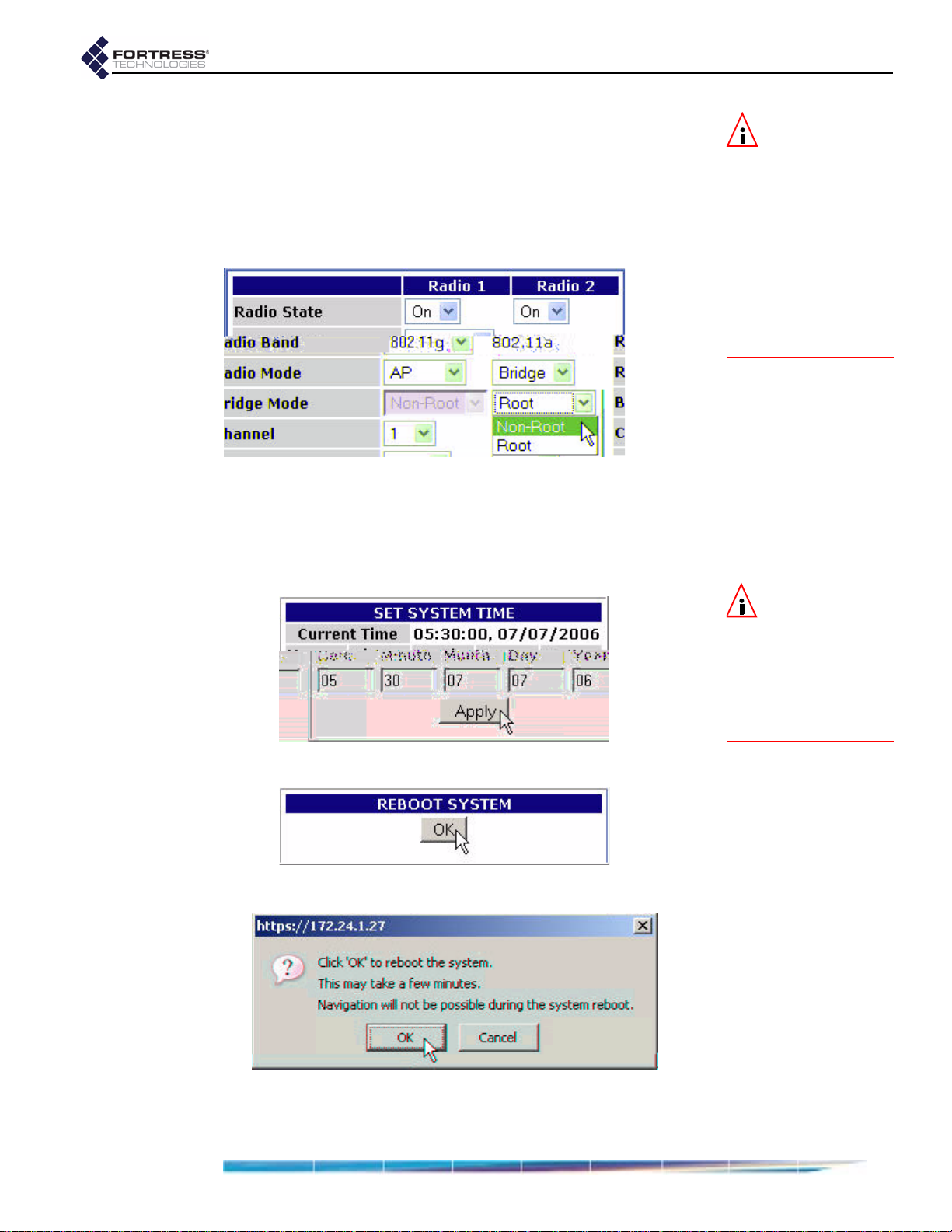
8 If the Fortress Bridge is the root node in the point-to-point/
multipoint deployment, skip this step.
or
If the Fortress Bridge is the non-root node in the point-topoint/multipoint deployment, choose
RADIO SETTINGS from
the main menu and in Bridge Mode setting for Radio 2,
choose
9 From the main menu on the left choose SYSTEM OPTIONS, and
on the
Non-Root, and click Apply.
SYSTEM OPTIONS screen, in the SET SYSTEM TIME
section, enter the correct date and time in the fields
provided, using two-digit values (
Apply.
detail:
hh:mm MM:DD:YY), and click
NOTE: If you are
deploying multi-
ple Fortress Bridges in a
point-to-point/multi-
point network they
must be correctly con-
figured for their net-
work roles, typically
with one serving as the
root node and the rest
configured as non-root
nodes (refer to Section
2.2 for more detail).
NOTE: The SYSTEM
OPTIONS
screen
features an information-
al timestamp under
SYSTEM
TIME. The re-
SET
fresh function of your
browser updates this
timestamp.
10 On the same screen, under REBOOT SYSTEM, click OK.
detail:
11 Click OK again to clear the system dialog.
12 Close your browser.
15
Page 26

Fortress Wireless Access Bridge: Installation
13 After the Bridge reboots, change the CLI password
(according to the instructions in Section 6.4.4.2) and
configure unique SSIDs for the Bridge (according to the
instructions in Section 3.3).
If you want to use the received signal strength indicator
(RSSI) to aim the antenna of a non-root Bridge, you may
want to enable it now (refer to Section 3.3.2.7).
14 Disconnect the LAN, WAN and ant enna ports in advance of
weatherizing and mast-mounting the Bridge.
2.4.3 Weatherizing the Bridge
All front-panel ports must be disconnected before you can
install the Weatherizing Kit.
To install the Weatherizing Kit:
1 Install the RJ-45 connector boot assembly on the end of the
cable that you will be plugging into the Fortress Bridge’s
WAN port, as shown in Figure 2.2:
If the RJ-45 connector is equipped with a molded
plastic boot, remove it from the connector. (Some
Ethernet cable connectors have a molded plastic outer
casing that is not designed for removal. This style of
connector is incompatible with the connector boot.)
NOTE: The Bridge
CLI provides ac-
cess to some configu-
ration settings that
cannot be accessed
from the Bridge GUI.
CAUTION: Do not
assemble the con-
nector boot without first
referring to these in-
structions. Several as-
sembly steps are
irreversible.
assembled connector
boots are unusable
and cannot be disassem-
bled.
Incorrectly
,
Figure 2.2 Installing the RJ-45 Connector Boot Assembly
16
Page 27
Fortress Wireless Access Bridge: Installation
Slide the compression nut, with the threaded opening
facing toward the connector, over the connector and
onto the cable.
Slide the compression bushing over the connector and
onto the cable.
Slide the threaded coupler, with the flanged end facing
toward the compression nut and bushing, over the
connector and onto the cable.
With the smooth-side prongs on the two halves of the
connector collar facing out and aligned with the RJ-45
connector’s locking tab, fit the collar around the
connector so that the connector’s locking tab is
compressed (the contact end of the connector extends
approximately 1/2" from the collar). Fit the outer tabs on
one half of the connector collar into the slots of the
other, and squeeze the two halves of the connector
collar together until they snap into place.
Align the primary key tab on the inner ring of the
connector boot with the cable connector’s locking tab.
Maintaining this alignment, fit the RJ-45 connectorcollar assembly into the boot through the boot’s
threaded end and snap the collar tabs into the boot
slots. Screw the connector boot securely onto the
threaded coupler.
Fit the compression bushing into the flanged end of the
threaded connector, and fit the compression nut over
the flanges. Screw the compression nut securely onto
the threaded connector until the bushing is compressed
around the cable to provide a water seal.
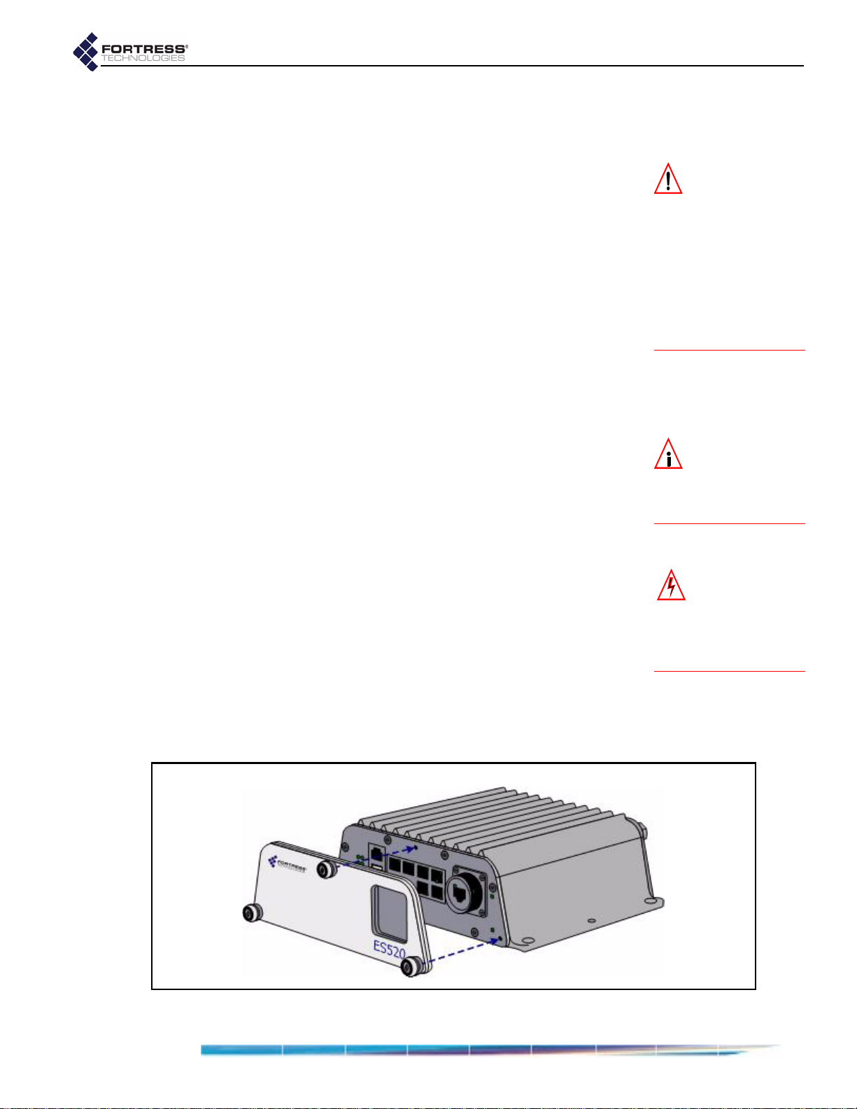
2 Attach the cover plate to the Bridge’s front panel with the
plate’s three captive screws, as shown in Figure 2.3.
CAUTION: There
are four different
possible alignments be-
tween the RJ-45 connec-
tor and the connector
boot. If the boot and
connector are not in the
correct alignment, the
RJ-45 connector will not
plug into the Bridge’s
WA N p o r t .
NOTE: Plugging
the connector/boot
into the
WAN port is de-
scribed in Step 4 of Sec-
tion 2.4.5.
WARNING: To
avoid the risk of
severe electrical shock,
do no t rem o ve the c o ve r
plate while the Fortre ss
Bridge is out of doors.
3 If only one antenna will be attached to the Bridge, screw the
antenna port cap onto the unused antenna port.
Figure 2.3 Attaching the Front-panel Cover Plate
17
Page 28

2.4.4 Mast Mounting the Bridge
The Mast-Mounting Kit accommodates masts from 1.5" to 3" in
diameter.
To install the Mast-Mounting Kit:
1 Position the Bridge at the desired position on the mast, with
the Bridge’s underside facing toward the mast a nd the front
panel facing down, as shown in Figure 2.4
2 Sandwich the mast between the underside of the Bridge
and the mounting bracket, fitting the mast into the bracket’ s
toothed cut-outs.
3 Place a split lock washer on each of the two hex bolts,
sliding them down to the head of the bolt.
4 Fit the bolts through the bolt holes in the mounting bracket
and then into the mounting holes in the underside of the
Bridge.
5 Tighten the bolts securely, until the split lock washers are
flattened between the bolt heads and the mounting bracket.
Fortress Wireless Access Bridge: Installation
Figure 2.4 Attaching the Mast-Mounting Bracket and Grounding Stud
2.4.5 Reconnecting the Bridge for Outdoor Operation
Review the Radio Frequency Safety Requirements (Section
2.2.4) before installing or operating Bridge radios.
1 Connect the rear-panel grounding stud (shown in Figure
2.4) to protective earth ground with a 20 gauge (minimum)
cable.
2 Connect a waterproof, standard 802.11a/b/g-capable
antenna with an N-type male connector to antenna port 1
(
ANT1).
3 Connect an antenna cable with a N-type male connector
between antenna port 2 (
ANT2) and a high-gain
WARNING: To
comply with FCC
rules, antennas must be
professionally installed.
Improperly grounded
outdoor antennas pose a
particularly serious
safety hazard.
18
Page 29

omnidirectional or directional antenna. The antenna and
cable must be waterproof.
4 Connect the Bridge's WAN port to an external 802.3af PSE/
PoE (Power Sourcing Equipment/Power over Ethernet)
source, which—if the
or a DSL or cable modem—provides an in-line connection
to the necessary network device.
To plug in the RJ-45 connector with the boot assembly
installed: orient the connecto r correctly with the W AN port,
and then twist the outer ring of the connector boot
clockwise until the channels in the ring align with the
locking studs on the Bridge’s WAN port casing. Continue
twisting the boot’s outer ring clockwise until the locking
channels are fully engaged and the boot is flush with the
port casing. A distinct click in the final turn of the boot’s
outer ring indicates that connector and boot are securely
plugged into the Bridge. (Installing the connector boot
assembly is covered in Section 2.4.3.)
2.5 Indoor Installation
Fortress Wireless Access Bridge: Installation
WAN port will connect to a satellite link
NOTE: Third par-
ty antennas are
subject to local regulato-
ry requirements. For
outdoor installations,
they must be water-
proof.
Figure 2.5 Indoor Fortress Bridge Connections
2.5.1 Connecting the Bridge for Indoor Operation
When the Fortress Bridge is installed indoors, it can be located
directly on a desktop with no additional hardware, or it can be
wall mounted, in any orientation—with four, #8, 3/4" wallanchored, flathead screws—through the mounting holes in the
chassis’s four corners.
19
Page 30

Fortress Wireless Access Bridge: Installation
1 Position the Bridge so that it operates only within its safe
temperature range (14º–122º F/
2 Connect a standard 802.11a/b/g-capable antenna with an
N-type male connector to antenna port 1 (
3 Connect an antenna cable with an N-type male connector
between antenna port 2 (
ANT2) and a high-gain
–
10º–50º C).
ANT1).
omnidirectional or directional antenna.
4 Connect the Bridge to at least one power source:
Connect the external +48V DC power supply that came
with the Bridge to the front-panel
+48V DC power inlet
and plug the power supply into a properly rated AC
power outlet with the cord provided.
and/or
Connect the Bridge’s WAN port to an external 802.3af
PSE/PoE (Power Sourcing E q uipment/Power over
Ethernet) source. (If the
WAN port will connect the
Bridge to a satellite link or a DSL or cable modem,
ensure the PSE/PoE source is in line with the
necessary network device.)
5 Connect up to eight wired LAN devices to the RJ-45
Ethernet ports (numbered
6 If the WAN port will connect the Bridge to a satellite link or a
1-8).
DSL or cable modem (and it was not connected in Step 4),
connect the 10/100
WAN Ethernet port to the necessary
network device.
7 Verify that all link/activity and power LEDs illuminate for all
connected ports.
CAUTION: The
FCC requires co-
located radio antennas
to be at least 7.9" apart.
The Bridge’s antenna
connectors are only 5"
apart. Avoid directly
mounting two antennas to
the Bridge’s rear-panel
connectors.
NOTE: When both
power supplies
are connected, the exter-
nal +48V power supply
is automatically selected
as the Bridge’s primary
power source.
2.5.2 Configuring the Bridge for Indoor Operation
Configuration procedures for an indoor Bridge are no different
from outdoor Bridge preconfiguration procedures. Follow step s
1 through 12, Section 2.4.2.
To access the Bridge GUI after initial configuration, use a new
instance of your browser and the IP address you set in Step 3
of Section 2.4.2.
20
Page 31

Chapter 3 Configuration
3.1 The Bridge GUI
The Fortress Wireless Access Bridge’s graphical user interface
provides access to Bridge administrative functions.
Fortress Bridge: Configuration
Access Bridge GUI help screens by clicking
on the main menu.
3.1.1 User Accounts
There are two user accounts on the Bridge GUI, and the
predetermined names associated with them are not userconfigurable.
The admin (administrator) account has full access to the all
functions and reconfiguration options on the Bridge.
The operator account can only view Bridge and network
settings and status. When the Bridge GUI is accessed
through the
operator account, the GUI functions used to
reconfigure the Bridge and the network it secures are not
displayed—or, when displayed, are grayed out.
3.1.2 Accessing the GUI
Y ou ca n access the Bridge GUI from any computer with access
to the Bridge—any computer in the Bridge-secured network’s
unencrypted zone, as well as any computer in the encrypted
zone and running the Fortress Secure Client.
If you are installing the Bridge for the first time, refer to Section
2.4.2.
To access the Bridge GUI:
1 Open a browser and, in the address field, enter the IP
address assigned to the Bridge’s management interface.
2 On the Login screen, enter the appropriate UserName:
admin or operator.
3 Enter the account Password.
4 Click Login.
Help, the last link
NOTE: The default
IP address is
192.168.254.254. Default
passwords are the ac-
counts’ respective user
names:
tor
changed during installa-
tion.)
admin and opera-
. (These should be
21
Page 32
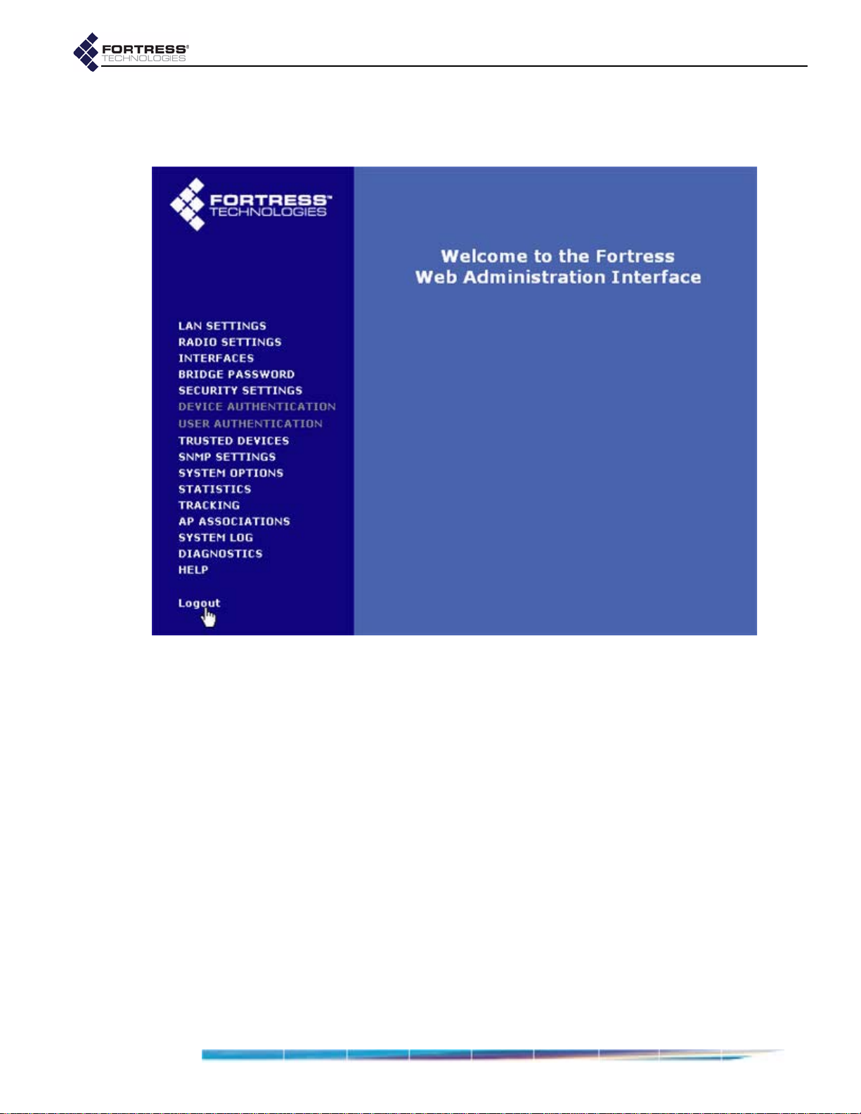
The Bridge GUI opens on the Welcome screen. Configuration
settings are accessed through the main menu links on the left
of the screen.
Fortress Bridge: Configuration
3.1.3 Logging Off
To log off the Bridge GUI, click Logout (below the main menu).
If you simply close the browser you have used to access the
Bridge GUI, you will automatically be logged off. (If you are
using Firefox’s tabbed browsing, you will only be logged off
when you close the active browser instance completely.
Closing only the Bridge GUI’s active tab in the browser will not
log you off.)
3.2 LAN Settings
LAN settings are those that configure network access to the
Bridge’s management interface: its network host name, IP
address, subnet mask, and default gateway.
Additionally, the Bridge’s STP (Spanning Tree Protocol) and
WAN port encryption options are configured on this screen.
22
Page 33

3.2.1 Spanning Tree Protocol
STP is a link management protocol that prevents bridging
loops on the network while providing path redundancy. You
should enable it only in deployments in which multiple OSI
layer 2 paths to the same device(s)—i.e., bridging loops—are
possible.
STP requires multicasting capability. When
Multicast—which is configured, per radio, on the RADIO
SETTINGS screen—is automatically Enabled for both of the
Bridge’s internal radios and the fields that configure the setting
(on the
RADIO SETTINGS screen) are grayed out.
Fortress Bridge: Configuration
NOTE: Bridging
loops can occur on
a WLAN only when
multiple APs share the
same ESS (extended ser-
vice set).
STP is Enabled,
The only radio to which multicasting applies is one with a
Mode setting of Bridge and a Bridge Mode setting of Non-Root. If
you disable STP on the
(on the
RADIO SETTINGS screen) of any radio so configured will
LAN SETTINGS screen, the Multicast field
be enabled, giving you the option of turning multicasting off for
that radio. (Refer to Section 3.3.2.6 for more detail on the
multicast function of Bridge radios.)
If you enable STP on the Bridge, you should enable it across all
devices on the Bridge-secured network.
3.2.2 WAN Port Encryption
By default, the Bridge’s WAN port is in the encrypted zone of
the Bridge-secured network, in which all traffic on the port is
encrypted.
It can be configured to be in the network’s unencrypted zone
and so to pass unencrypted traffic (cleartext).
The encrypted and unencrypted zones are mutually exclusive
and the WAN port cannot be in both zones at once.
Radio
23
Page 34
Fortress Bridge: Configuration
To reconfigure Bridge LAN settings:
1 Log on to the Bridge GUI admin account and select LAN
SETTINGS from the menu on the left.
2 On the LAN SETTINGS screen, make your changes to the
relevant field(s). These include:
Host name - a descriptive name for the Bridge
LAN IP address - the network address of the Bridge
LAN Subnet mask - the correct subnet mask for the
Bridge
Default gateway - the IP address of the default gateway
STP - enables/disables Spanning Tree Protocol
(enabled by default)
WAN Port - configures the WAN port to reside in either
the encrypted zone of the Bridge-secured network or in
the unencrypted zone.
Click Apply.
3 Click OK on the system prompt that instructs you to reboot.
4 Follow the instructions in Section 4.7 to reboot the Bridge.
You must use a new instance of the browser (and the new
IP address, if it has changed) when you next access the
Bridge’s management interface.
3.3 Radio Settings
NOTE: The IP ad-
dress you assign
must be unique on the
network.
CAUTION: If the
WAN port is pro-
viding the link to an un-
encrypted interface,
such as a cable or DSL
modem or satellite up-
link, the WAN port
must reside in the net-
work’s unencrypt ed
zone.
NOTE: If you are
using Firefox’s
tabbed browsing, you
must close the active
browser instance com-
pletely—not just Bridge
GUI’s active tab in the
browser.
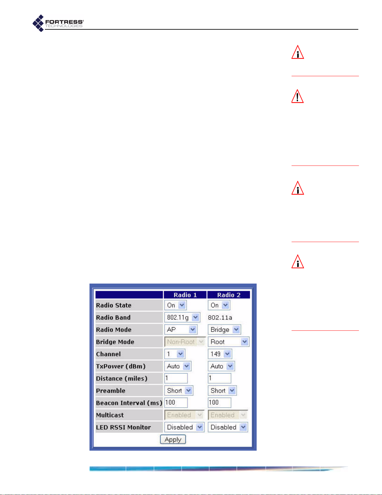
The Fortress Bridge is equipped with two, independent internal
radios, the basic configuration settings for which appear on the
RADIO SETTINGS screen. The default settings are shown below.
NOTE: Additional
radio interface set-
tings can be configured
through
POINT SETTINGS (accessi-
ble from the
VIRTUAL ACCESS
INTERFACES
screen, Section 3.3.4)
and through the Con-
troller CLI (sections
6.4.3 and 6.7).
24
Page 35

Fortress Bridge: Configuration
Radio 1 is the tri-band 802.11a/b/g radio, which can be
configured as an 802.11g or an 802.11a radio.
Radio 2 always
functions as an 802.11a radio.
RADIO SETTINGS fields are described in sections 3.3.1 and 3.3.2.
Section 3.3.3 provides step-by-step instructions to change
them.
3.3.1 Radio State, Band and Mode Settings
The first four settings on the RADIO SETTINGS screen determine
whether and how the radio will be used in the network
implementation.
3.3.1.1 Radio State
The
Radio State setting simply turns the radio On and Off. Both
radios are on by default.
3.3.1.2 Radio Band
Radio 1 can operate on either the 802.11a, 5 Ghz band or
Only
the
802.11g, 2.4 Ghz band, according to your selection in the
Radio Band field. By default, 802.11g is selected for Radio 1.
Radio 2 can function only on the 802.11a band.
3.3.1.3 Radio Mode
Either radio can operate in either of two modes:
NOTE: 802.11b de-
vices are fully
compatible with the
802.11g radio.
NOTE: Radio 1 uses
antenna port 1
(ANT1); Radio 2 uses an-
tenna port 2 (ANT2).
AP - A radio in AP mode functions exclusively as a wireless
access point, allowing connections only from wireless
devices. It does not permit connections to or from other
Fortress Bridges.
Bridge - A radio in Bridge mode functions as network bridge
in a point-to-point/multipoint network of other Fortress
Bridges, and it allows connections from wireless devices. In
Bridge mode, then, a radio can serve simultaneously as a
network bridge and as a wireless AP.
By default,
Radio 1 is in AP mode and Radio 2 is in Bridge
mode.
3.3.1.4 Bridge Mode
When deploying the Fortress Bridge as a wireless bridge in a
point-to-point or point-to-multipoint network—with a
setting of Bridge on one of the internal radios— you must
Mode
correctly configure the radio used for bridging for its network
role, by selecting one of two possible
Root - A radio with a Bridge Mode of Root does not initiate
connections with other Fortress Bridges. Radios in root
mode only receive connections initiated by other devices—
either from the radios of other Bridges (in
or from wireless devices.
Radio
Bridge Mode settings:
Non-Root mode)
NOTE: Yo u c a n
also change the
Bridge Mode of Radio 2
through the Bridge’s
front-panel switches (re-
fer to Section 3.10.1.1).
25
Page 36

Non-Root - Radios in Non-Root mode do initiate connections
with other Fortress Bridges—either directly with a root
Bridge or with other non-root Bridges (as well as receiving
connections from other non-root Bridges and wireless
devices).
Typically, one Bridge serves as the root node (or root Bridge)
and any other Bridges in the deployment are configured as
non-root nodes.
Fortress Bridge: Configuration
In the Bridge’s default configuration, only
with a
Radio Mode of Bridge, and it is in Root mode.
Radio 2 is configured
3.3.2 Radio Transmission and Reception Settings
In addition to establishing the basic uses and roles of the
Bridge’s internal radios (Section Section 3.3.1), you can
configure a number of operating parameters through the Bridge
GUI.
3.3.2.1 Channel
Channel setting selects the portion of the radio spectrum
The
over which the radio will communicate.
Radios in non-root bridging mode do not bind to a channel, but
rather to an SSID. The
out for either radio with a
Bridge Mode setting of Non-Root.
The channels available for a radio in
Bridge Mode are a function of the frequency band it uses.
On Radio 2 and Radio 1 when it is configured to use the
802.1 1a band, you can sele ct channels
60, 64, 149, 153, 157, or 161.
On Radio 1, when it is configured to use the 802.11g band,
you can select channels
The default channel setting for
802.1 1G band is
1; on the 802.1 1a band it s default setting is 36.
The default channel setting of
Channel setting will therefore be grayed
Radio Mode setting of Bridge and a
AP Radio Mode or in Root
36, 40, 44, 48, 52, 56,
1–11, inclusive.
Radio 1 when it is using the
Radio 2 is 149.
CAUTION:
to-point/multi-
point deployments the
radios used to connect
the networked Bridges
must be configured with
identical transmission
and reception settings.
In point-
Selectable channel options for
Radio Band selection made for it. (Radio 2 is fixed on the
802.11a band; its channel selection options do not change.)
3.3.2.2 Transmit Power
TxPower setting specifies the power level at which the
The
radio will transmit—from
milliwatts), in increments of 1 dBm—or, by selecting
default for both radios), which configures the radio to transmit
at maximum power (26 dBm for both radios).
In environments with a dense distribution of APs (and resulting
potential for interference), it may be desirable to select a lower
TxPower setting than the default (Auto) for Radio 1 when it is
configured to use the 802.11g band. The
otherwise appropriate for both radios.
Radio 1 therefore depend on the
1 to 18 dBm (decibels referenced to
Auto (the
Auto setting is
26
Page 37

3.3.2.3 Distance
The
Distance setting configures the maximum distance—from 1
to
35 miles, in increments of 1 mile—for which the radio must
adjust for the propagation delay of its transmissions.
Fortress Bridge: Configuration
Figure 3.1. Point-to-multipoint Bridge deployment with bridging radio
In a point-to-multipoint deployment, the Distance setting on the
networked radios of all member Bridges should be the number
of miles separating the two Bridges with the greatest,
unbridged distance between them. In Figure 3.1, above, the
Distance setting would be 3 miles: the longest distance in the
network between two Bridges without another Bridge between
them.
Propagation delay is not a concern at distances of one mile
and under, at which you should leave the setting at
default for both radios).
Additional radio configuration can be done through the Bridge
CLI (refer to Section 6.7).
3.3.2.4 Preamble
The short preamble is used by virtually all wireless devices
currently being produced. The default
Preamble setting of Short
is therefore optimal for most network implementations.
Some older 802.11b devices, however, still use the long
preamble, and if the network must support such devices, you
must configure the radio they will communicate with to use a
Preamble setting of Long.
Distance
1 mile (the
settings of 3 miles
27
Page 38

3.3.2.5 Beacon Interval
The Bridge’s radios transmit beacons at regular intervals to
announce their presence on the network. You can configure
the number of milliseconds between beacons in whole
numbers between
beacon.
Fortress Bridge: Configuration
25 and 1000. You cannot disable the
The default beacon interval is
3.3.2.6 Multicasting
Wireless is an inherently broadcast medium. A multicast
packet, like any other, is broadcast (by the root Bridge) to all
nodes (non-root Bridges) on the wireless network. Each nonroot Bridge then examines the packet and:
If the Bridge is an intended receiver, it accepts the packet.
and/or
If the Bridge is serving as a repeater for an outlying Bridge
that is an intended receiver, it passes the packet along this
route.
or
If the Bridge is neither an intended receiver nor the
repeater for an intended receiver, it drops the packet.
Non-root Bridges on which
multicast packets.
The
Multicast function applies exclusively to non-root Bridges,
and so can only be
setting of
detail:
Bridge and a Bridge Mode setting of Non-Root.
100 milliseconds.
Multicast is disabled will drop all
Enabled on Bridges with a Radio Mode
Multicast field is grayed out for Bridges with a Radio Mode
The
of
AP or with a Bridge Mode of Root.
Multicast field is also grayed out for Bridge’s with STP
The
Enabled on the LAN SETTINGS screen. Because STP requires
multicasting capability,
the field that configures the setting is grayed out) when
Multicast is automatically Enabled (and
STP is
28
Page 39

Enabled on the LAN SETTINGS screen. If you disable STP on a
non-root Bridge, the
setting of Bridge and a Bridge Mode setting of Non-Root
Mode
Multicast field for the radio with a Radio
will be configurable. Refer to Section 3.2.1 for more information
on STP.
3.3.2.7 Received Signal Strength Indicator
In outdoor, point-to-point/multipoint installations, the LED RSSI
Monitor
allows you to make the first adjustments to the
directional antenna(s) of the non-root Bridge(s) in the network.
When the
LED RSSI Monitor is Enabled on a given radio, all
other monitoring functions of both of the front-panel LEDs for
that radio (described in Section 5.6.2) are disabled.
Then, as you point a directional antenna of a non-root Bridge
toward the root Bridge, the lower LED for that radio dynamically
indicates the strength of the signal received from the root
Bridge, as shown in Table 3.1.
LED RSSI Monitor is Disabled by default.
The
Fortress Bridge: Configuration
NOTE: Because ra-
dios in
Mode
or in Root Bridge
Mode
accept multiple, si-
multaneously connec-
tions, the
Monitor
is not used to set
up radios configured in
this way (although it re-
mains available).
AP Radio
LED RSSI
Table 3.1. RSSI Behaviors and Meanings in Radio LEDs
Behavior Meaning
off
slow green flash (approx. 1 Hz)
fast green flash (approx. 4 Hz)
steady green
poor connection (signal level ≤ -85 dBm)
good connection (signal level > -85 dBm but < -60 dBm)
excellent connection (signal level > -60 dBm)
no connection
3.3.3 Configuring Basic Radio Settings
1 Log on to the Bridge GUI admin account and select RADIO
SETTINGS from the menu on the left.
2 On the RADIO SETTINGS screen, in the column that
corresponds to the radio you want to configure, enter new
values into the relevant fields (described in sections 3.3.1
and 3.3.2).
3 Click Apply at the bottom of the screen.
4 If a system prompt instructs you to reboot, click OK.
5 If you changed TxPower to Auto, or you were prompted to
reboot the Bridge, follow the instructions in Section 4.7.
3.3.4 Virtual Radio Interface Settings
A radio with a radio mode of Bridge, whether it is configured as
a root or a non-root bridge, can comprise only a single Virtual
Access Point (or
VAP), with its single associated SSID.
NOTE: When you
change
from Auto to another
value, the change takes
effect immediately.
When you change the
setting from another
valu e to
reboot Bridge in order
to effect the change.
Auto, you must
TxPower
A radio with a
radio mode of AP, can comprise up to four VAPs
each with its own SSID and associated settings.
By default, only one VAP is configured per radio, regardless of
the radio
Mode settings. You can however observe the added,
29
Page 40

unconfigured VAPs for radios in AP radio mode on the VIRTUAL
A
CCESS POINTS display frame on the INTERFACES screen.
You can view the settings that assign SSIDs (and associated
settings) for the radio’s VAPs in the
frame on the
INTERFACES screen. The Edit button for each VAP
VIRTUAL ACCESS POINTS
provides access to the fields that configure these settings.
Fortress Bridge: Configuration
Sections 3.3.4.1 through 3.3.4.5 describe the fields available
through the
Section 3.3.4.6 provides step-by-step instructions to configure
them.
3.3.4.1 SSID
The service set identifier associated with each VAP is a unique
string of up to 32 characters included in the packet headers of
wireless traffic. SSIDs are used like passwords to identify
which devices can connect to the wireless network and to
determine the parameters of their access once they are
connected.
Edit buttons in the VIRTUAL ACCESS POINTS frame.
CAUTION: The net-
work is not fully
secure until the radio
SSIDs have been
changed from their de-
fault settings.
30
Page 41

Radio 1 is preconfigured with a default SSID of Base-11g; the
default SSID for
Radio 2 is Base-11a.
3.3.4.2 Hide SSID and Accept G Only Options
To the right of the SSID field are two options that you can
enable through their checkboxes:
Hide SSID - Enabling this option deletes the SSID string
from the packet headers of beacon and probe responses. It
is disabled by default.
Accept G Only - Enabling this option prevents 802.11b
wireless devices from connecting to
Radio 1 when it is
configured to use the 802.11g band. When this option is
disabled (the default), Radio 1 (configured with a
of 802.11g) accepts connections from both 802.11g
Band
and 802.11b devices.
3.3.4.3 DTIM Period
APs buffer broadcast and multicast messages for devices on
the network and then send a Delivery Traffic Indication
Message to “wake-up” any inactive devices and inform all
network clients that the buffered messages will be sent after a
specified number of beacons have been transmitted. (The
beacon interval, described in Section 3.3.2.5, is configured on
the
RADIO SETTINGS screen.)
Fortress Bridge: Configuration
Radio
DTIM Period determines the number of beacons in the
The
countdown between transmitting the initial DTIM and sending
the buffered messages. Whole values from
are accepted; the default is
1.
3.3.4.4 RTS and Fragmentation Thresholds
RTS Threshold allows you to configure the maximum size
The
of the frames the VAP sends without using the RTS/CTS
protocol. Frame sizes over the specified threshold cause the
V AP to first se nd a Request to Send message and then receive
a Clear to Send message from the destination device before
transmitting the frame.
RTS Threshold is measured in bytes. Zero (0) and whole
The
values between
Threshold
The
value of 0 turns off RTS/CTS for all frames.
Frag. Threshold allows you configure the maximum size of
1 and 2345 are accepted. The default RTS
the frames the VAP sends whole. Frame sizes over the
specified threshold are broken into smaller frames before they
are transmitted.
Frag. Threshold is measured in bytes. Zero (0) and whole
The
values between
Threshold
value of 0 turns off fragmentation for all frames (i.e.,
256 and 2345 are accepted. The default Frag.
frames will be sent whole regardless of size).
1 to 255, inclusive,
3.3.4.5 Security Suite and Security Suite Settings
31
Page 42

Fortress Bridge: Configuration
The security protocol(s) employed by the Bridge’s virtual
access point are configured per VAP.
Your selection in the
P
OINT SETTINGS frame determines which fields are configurable
(and which are grayed-out) in the S
Security Suite field of the VIRTUAL ACCESS
ECURITY SUITE SETTINGS
frame (in the lower half of the same screen), as described
below.
Cleartext Security
Selecting Cleartext as a VAP’s Security Suite essentially turns
off security measures for that VAP. Wireless devices
connected to the VAP send and receive all traffic in the clear
(i.e., unencrypted).
A
Security Suite setting of Cleartext requires no further
configuration.
Fortress Security
Selecting Fortress as a VAP’s Security Suite requires all traffic
on that VAP to use Fortress’s Mobile Security Protocol (MSP),
as configured on the Bridge itself (on the S
ECURITY SETTINGS
screen of the Bridge GUI or in the Bridge CLI).
When the
mode, you must select
Radio Mode is Bridge, whether in Root or Non-Root
Fortress as the Security Suite setting for
that radio’s single VAP.
NOTE:
curity Suite
require that an 802.1X
authentication server be
configured for the
Bridge. These include:
802.1X and those WPA
and WPA2 settings that
do not use PSK. Refer to
Section 3.4.1.
Certain
options
Se-
A
Security Suite setting of Fortress requires no further
configuration in the S
ECURITY SUITE SETTINGS frame.
Open WEP and Shared WEP
Open WEP (Wired Equivalent Privacy) and Shared WEP both
use static keys for data encryption. They are distinguished by
their authentication methods.
Open WEP operates on the assumption that the keys
configured on the VAP and on connecting devices have been
entered correctly. It allows devices to connect without
challenge and then uses the configured keys to encrypt the
data passing between the Bridge and the connected device.
Shared WEP does not allow a device to connect until it has
successfully encrypted a challenge sent by the VAP. When the
VAP’s challenge receives a correct response from the
connecting device, it allows the connection and then uses the
configured keys to encrypt the data passing between the
Bridge and the connected device.
Selecting
requires the same settings to be configured in the S
S
UITE SETTINGS frame. These include:
Open-WEP or Shared-WEP as a VAP’s Security Suite
ECURITY
WEP Key Length - WEP keys can be 104 or 40 bits long. 104-bit
is the default.
32
Page 43
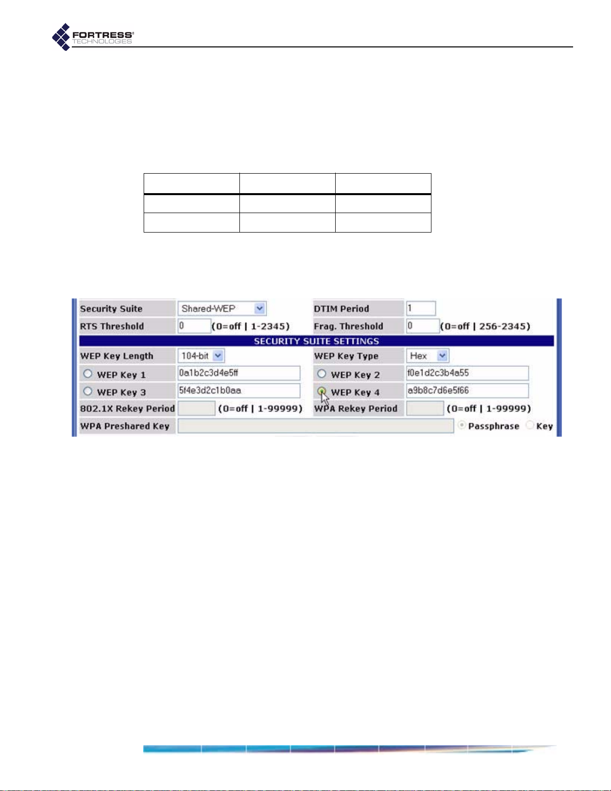
detail:
WEP Key Type - WEP keys can be composed of an ASCII
(plaintext) passphrase or hexadecimal string.
WEP Keys 1–4 - You must manually enter at least one static
Hex is the default.
key to be used in Open WEP and Shared WEP transactions,
within the specifications you set in the two fields above, which
determine the usable key lengths for these fields.
Table 3.2. Usable WEP Key Lengths
bit-length in hex in ASCII
104-bit 13 digits 7 characters
40-bit 10 digits 5 characters
Use the radio button to select the default transmit key: the key
to be used when transmitting multicast/broadcast messages on
the network.
Fortress Bridge: Configuration
802.1X Security
802.1X security uses WEP encryption with dynamically
generated keys rather than static keys for encryption.
The dynamic keys used when you select a
802.1X are generated and exchanged automatically at user-
Security Suite of
specified intervals. This interval is the only additional setting
required for 802.1X security. Specify the interval in seconds in
the
802.1X Rekey Period field. Whole numbers between 0 and
99999, inclusive, are allowed. A value of 0 (zero), disables the
rekeying function; the keys used by connecting devices will
remain unchanged for the duration of their sessions.
WPA, WPA2 and WPA-Mixed Security
WPA (Wi-Fi Protected Access) and WPA2 are the enterprise
modes of these two WPA types (as distinguished from the
shared key modes described below).
You can specify that
WPA or WP A2 be used exclusively on a
pre-
given VAP, or you can configure a single VAP to be able to use
either (by selecting
WPA-Mixed), depending on the WPA type in
use by the connecting device.
33
Page 44

WPA and WPA2 generate encryption keys dynamically and
exchange keys automatically with connected devices at userspecified intervals. This interval is the only additional setting
required for WP A security. Specify the interval in seconds in the
WP A Rekey Period field. Whole numbers be tween 0 and 99999,
inclusive, are allowed. A value of
0 (zero), disables the
rekeying function; the keys used by connecting devices will
remain unchanged for the duration of their sessions.
WPA-PSK, WPA2-PSK and WPA-Mixed-PSK Security
WPA-PSK (Wi-Fi Protected Access) and WPA2-PSK are the
pre-shared key modes of these two WPA types (as
distinguished from the
enterprise modes described above).
Pre-shared key mode differs from enterprise mode in that PSK
bases its key generation on a user-specified key or
passphrase.
Fortress Bridge: Configuration
You can specify that
WPA-PSK or WPA2-PSK be used
exclusively on a given VAP, or you can configure a single VAP
to be able to use either (by selecting
WPA-Mixed-PSK),
depending on the WPA-PSK type in use by the connecting
device.
Like enterprise-mode WPA, WPA-PSK and WPA2-PSK
generate encryption keys dynamically and exchange keys
automatically with connected devices at user-specified
intervals. Specify the interval in seconds in the
Period field. Whole numbers between 0 and 99999, inclusive,
are allowed. A value of
0 (zero), disables the rekeying function;
the keys used by connecting devices will remain unchanged for
the duration of their sessions.
Additionally you must enter the
WP A Preshare d Key itself, in the
form of either a plaintext passphrase between 8 and 63
characters in length or a 64-digit hexadecimal string, and then
use the radio buttons to specify whether the key is a
Passphrase or a hexadecimal Key.
3.3.4.6 Configuring Virtual Radio Settings
1 Log on to the Bridge GUI admin account and select
INTERFACES from the menu on the left.
2 In the VIRTUAL ACCESS POINTS frame, click the Edit button for
the VAP you want to configure.
3 Select and/or enter the values you want to set for the VAP.
Your options are described in sections 3.3.4.1 through
3.3.4.5).
4 Click Apply at the bottom of the screen.
WPA Rekey
34
Page 45

3.4 802.1X Server and LAN Port Settings
Fortress Bridge: Configuration
The Fortress Bridge can be used with an external 802.1X
authentication server and its internal switch ports can be
individually configured to allow or block 802.1X traffic.
The Fortress Bridge supports
non-802.1X authentication
through a separate and unrelated set of configuration settings.
The global settings for non-802.1X authentication are
described in Section 3.6.6. Individual non-802.1X device and
user authentication settings are described in sections 4.1 and
4.2, respectively.
3.4.1 802.1X Authentication Server
When an 802.1X authentication server is configured for it, the
Bridge acts as an 802.1X authenticator, conveying 802.1X
queries and responses between 802.1X supplicants and the
configured authentication server.
In order to support 802.1X authentication—whether for
wireless (
(Section 3.4.2)—the Bridge must be configured to use an
external, 802.1X authentication server.
Certain other VAP
WPA and WPA2 options that do
mode)—also require the use of an 802.1.X authentication
server. (Possible VAP
detail in Section 3.3.4.5.)
Finally, even in configurations that do not require the use of an
802.1X authentication server, the fields that configure the
server cannot be empty
the default 802.1X authentication servers settings in place,
without reference to an actual 802.1X server.
802.1X Security in Section 3.3.4.5) or wired devices
Security Suite settings—specifically those
not use PSK (pre-shared key
Security Suite settings are described in
. In these instances, you can leave
NOTE: The RADI-
US server internal
to the Bridge cannot be
used for 802.1X authen-
tication.
NOTE: If you are
using both RADI-
US and 802.1X authenti-
cation services, they can
run on the same exter-
nal server, but you must
enter the server’s set-
tings both on the
TY SETTINGS screen (in
the
AUTHENTICATION SET-
TINGS section) and on the
INTERFACES screen (in the
802.1X AUTHENTICATION
SERVER frame).
SECURI-
Before configuring the Bridge to use the 802.1X authentication
server, you should first configure the service to use the Bridge
as an 802.1X authenticator (refer to your 802.1X server
documentation for guidance).
To configure the Bridge for use with
an external 802.1X authentication server:
1 Log on to the Bridge GUI admin account and select
INTERFACES from the menu on the left.
35
Page 46

2 In the 801.1X AUTHENTICATION SERVER frame:
In Server Address, enter the IP address of the network
802.1X authentication server (the default is
In Server Port, enter the port used by the server for
802.1X requests (the default is
In Auth Server Key , enter the shared key assigned to the
Bridge in the 802.1X service. (The default is
In Confirm Server Key, re-enter the shared key (to guard
against entry errors).
3 Click the frame’s Apply button.
3.4.2 LAN Port 802.1X Settings
The Bridge’s internal LAN switch can be configured, per port, to
require that the connected device is an 802.1X supplicant
successfully authenticated by the 802.1X server configured for
the Bridge (Section 3.4.1).
1812).
127.0.0.1
fortress.)
Fortress Bridge: Configuration
NOTE: The server
).
key you enter here
should already be
present in the 802.1X au-
thentication service con-
figuration.
NOTE: The internal
LAN does not sup-
port NAT (network ad-
dress translation).
Configure this function in the
of the
INTERFACES screen, where the port numbers shown in
the GUI correspond to the numbered ports
LAN PORT 802.1X SETTINGS frame
1–8, as labeled on
the Bridge’s front panel (shown in Figure 2.1).
1 Log on to the Bridge GUI admin account and select
INTERFACES from the menu on the left.
2 In the LAN PORT 801.1X SETTINGS frame, use the dropdown
menu for each port to select whether:
the device connecting through the port will not be
required to authenticate through an 802.1X
authentication server:
Off (the default)
or
the device will be required to authenticate through the
802.1X server configured for the Bridge:
3 When you have made your selections for each of the
Bridge’s LAN ports, click the frame’s
Apply button.
On.
3.5 Bridge Passwords
Two passwords apply to the Bridge GUI, one for the admin
account, which grants full administrative permissions on the
Bridge, and one for the
only access. A third password is set for the Bridge CLI; it can
be changed only in the CLI (refer to Section 6.4.4.2).
operator account, which grants view-
36
Page 47

Fortress Bridge: Configuration
NOTE: For security
37
Page 48
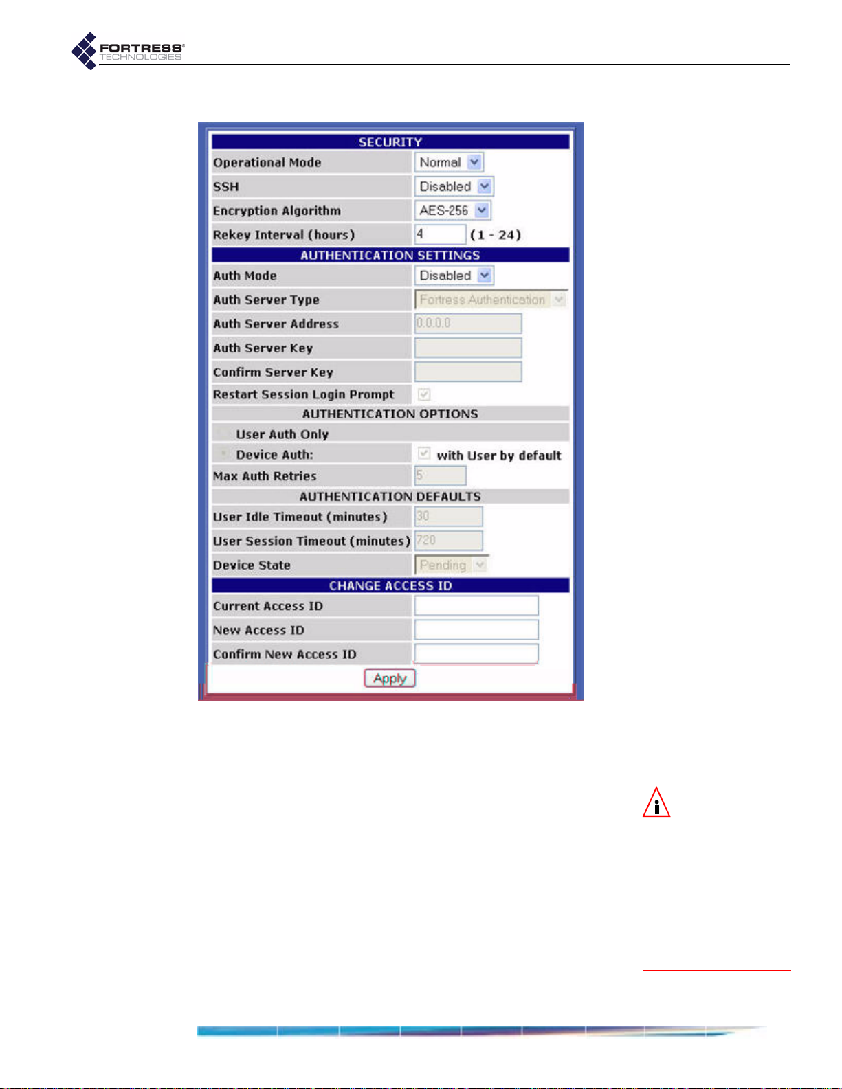
The viewable, default security settings are shown below.
Fortress Bridge: Configuration
3.6.1 Operating Mode
The Fortress Bridge can be operated in either of two modes:
Normal (the default) or FIPS.
FIPS operating mode is necessary for deployments and
applications that are required to comply with the Federal
Information Processing Standards (FIPS) for cryptographic
modules. The high levels of security that can be implemented
in the Fortress Security System’s
or exceed the needs of virtually all unregulated networked
environments.
FIPS operating mode is compliant with FIPS 140-2. It enforces
security measures beyond those of Normal operating mode,
the most significant of which include:
Normal operating mode meet
NOTE: The Bridge
(in either operat-
ing mode) flashes the
front-panel cleartext
LED (
Clr) whenever un-
encrypted data is pass-
ing in an encrypted
zone. In FIPS terminolo-
gy, the cleartext signal
indicates that the Bridge
is in Bypass Mode (BPM).
38
Page 49

If the Bridge fails any self-test on startup, it is rendered
inoperable and must be returned to the vendor for repair or
replacement.
Only a designated Crypto Officer, as defined by the Federal
Information Processing Standards, may perform
administrative functions on the Bridge and its Secure
Clients.
detail:
To change the Bridge operating mode:
1 Log on to the Bridge GUI admin account and select
SECURITY SETTINGS from the menu on the left.
2 In the SECURITY section of the SECURITY SETTINGS screen,
select the Bridge’s operating mode.
3 Click Apply at the bottom of the screen.
Fortress Bridge: Configuration
3.6.2 Secure Shell Access
In order to access the Bridge CLI from a network connection to
the Bridge’s management interface, Secure Shell (SSH) must
be enabled. When SSH is disabled, you can access the Bridge
CLI exclusively through a direct connection to its
Secure Shell (SSH) is disabled on the Bridge by default.
detail:
To configure SSH access to the Bridge CLI:
1 Log on to the Bridge GUI admin account and select
SECURITY SETTINGS from the menu on the left.
2 In the SECURITY section of the SECURITY SETTINGS screen,
select whether SSH is
3 Click Apply at the bottom of the screen.
Enabled or Disabled.
3.6.3 Encryption Algorithm
The Bridge supports the strong, AES encryption standard at
these user-specified key lengths:
AES-256 (default)
AES-192
AES-128
All Secure Clients logging on to the Bridge must be configured
to use the same encryption algorithm and key length as the
Console port.
39
Page 50
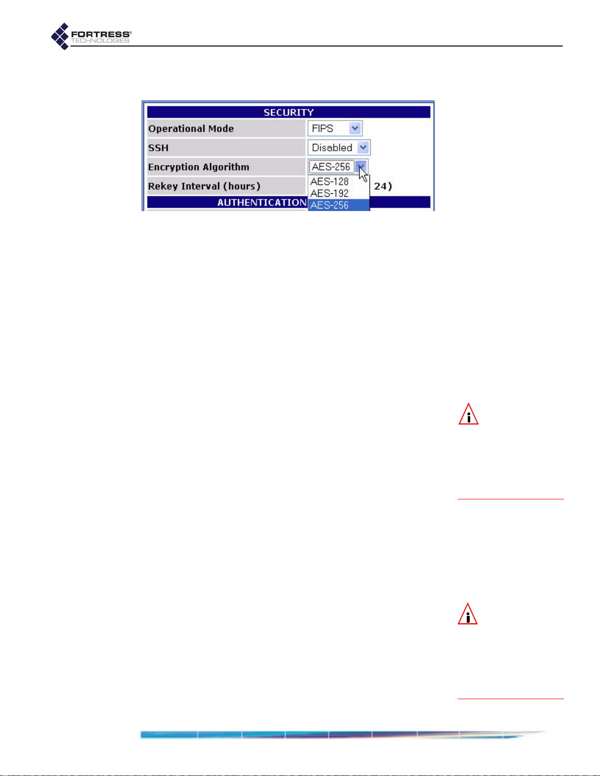
detail:
Fortress Bridge: Configuration
Bridge. For information on setting encryption algorithms on
Secure Clients, refer to your Fortress Secure Client user guide.
To change the Bridge encryption algorithm:
1 Log on to the Bridge GUI admin account and select
SECURITY SETTINGS from the menu on the left.
2 On the CRYPTO ALGORITHM section of the SECURITY
SETTINGS screen, select the AES key length to be used to
encrypt network data.
3 Click Apply at the bottom of the screen.
3.6.4 Re-keying Interval
The Fortress Bridge generates new keys at defined intervals,
renegotiating dynamic keys with Secure Clients whenever
those Clients are logged on. You can specify the re-keying
interval, in hours, at values between 1 and 24. The default is 4.
At the default, for example, to decrypt data intercepted over a
twelve-hour period, a hacker would have to recover three sets
of keys from the Bridge, in addition to the keys generated by
connecting devices’ re-keying behaviors, quickly enough to use
them before the next re-key—the possibility of which is
vanishingly remote.
To change the Bridge’s re-keying interval:
1 Log on to the Bridge GUI admin account and select
SECURITY SETTINGS from the menu on the left.
2 On the RE-KEYING INTERVAL section of the SECURITY
SETTINGS screen, select the number of hours, in whole
numbers from 1 to 24, that will elapse between new key
negotiations with the Bridge.
3 Click Apply at the bottom of the screen.
3.6.5 Access ID
The Access ID provides network authentication for the Fortress
Security System. This 16-digit hexadecimal ID is established
during Bridge installation, after which the same Access ID must
be specified for every Fortress Secure Client of the Bridge.
Likewise, if you change the Bridge’s Access ID, you must
subsequently make the same change to all of its Secure
Clients’ Access IDs. For information on setting the Access ID
NOTE: Every new
key negotiation
adds network traffic,
and the increased secu-
rity of shorter re-keying
intervals should be bal-
anced against through-
put considerations.
NOTE: The default
Access ID is repre-
sented by 16 zeros or
the word
when configured as a
new Access ID, returns
the Bridge’s Access ID to
its default setting.
default, which,
40
Page 51

detail:
Fortress Bridge: Configuration
on Secure Clients, refer to your Fortress Secure Client user
guide.
To change the Bridge’s Access ID
1 Log on to the Bridge GUI admin account and select
SECURITY SETTINGS from the menu on the left.
2 In the CHANGE ACCESS ID frame of the SECURITY SETTINGS
screen:
Enter the Current Access ID.
Enter a 16-digit hexadecimal number to serve as the
New Access ID.
Re-enter the new Access ID in Confirm New Access ID.
3 Click Apply at the bottom of the screen.
3.6.6 Non-802.1X Authentication Global and Default Settings
The settings that enable and disable non-802.1X device and
user authentication on the Fortress Bridge are located in the
AUTHENTICATION SETTINGS frame of the SECURITY SETTINGS
screen.
802.1X Security, in Section 3.3.4.5, describes the settings that
select and configure 802.1X authentication for wireless
devices. Section 3.4 covers
Settings
.
802.1X Server and LAN Port
CAUTION: For se-
curity reasons, the
Access ID in effect on
the Bridge cannot be
displayed. Make a note of
the new Access ID: you
will need it to configure
the Bridge’s Secure Cli-
ents, as well as to
change the Access ID on
the Bridge.
NOTE: The Bridge
supports 802.1X
authentication through
separate and unrelated
configuration settings.
This screen is also where the global setting for the maximum
number of allowable authentication attempts is set and where
the session timeout login prompt is disabled/enabled.
Default values for new devices and users are configured on the
SECURITY SETTINGS screen as well.
Subsequent authentication configuration options are
determined by whether you choose to enable authentication
and, if you do, whether you implement authentication locally or
through an external RADIUS (Remote Authentication Dial-In
User Service) server. Your choices are also affected by
whether you use both user and device authentication. The
availability of Bridge GUI
AUTHENTICATION SETTINGS reflects
these differences when you apply new settings.
The Bridge GUI includes separate, dedicated screens to
manage authentication for devices and for users. These
screens are only available when
Local authentication has been
NOTE: To support
smart cards au-
thenticated through PKI
(Public Key Infrastruc-
ture), the Bridge must
be configured to use an
External RADIUS server
that supports EAP-TLS
authentication. (Refer to
your RA DIUS docu -
mentation for guidance
on configuring the ser-
vice.)
41
Page 52

selected and, in the case of device authentication, when it has
been globally enabled in the
the
SECURITY SETTINGS screen. These screens are described in
AUTHENTICATION SETTINGS frame of
Section 4.1 (Device Authentication) and Section 4.2 (User
Authentication), in the next chapter.
3.6.6.1 Enabling/Disabling Authentication Globally
The Fortress Bridge has an internal RADIUS server built-in.
The Bridge additionally supports an external RADIUS server.
Authentication (device and user) is disabled/enabled globally
on the Bridge by selecting
AUTHENTICATION SETTINGS frame of the SECURITY SETTINGS
Disabled, Local or External in the
screen.
detail:
Fortress Bridge: Configuration
To enable/disable all authentication:
1 Log on to the Bridge GUI admin account and select
SECURITY SETTINGS from the menu on the left.
2 In the AUTHENTICATION SETTINGS frame, in the Mode field,
select one of:
Disabled - disables authentication (the default)
Local - enables authentication through the Bridge’s
internal RADIUS server (and enables local
configuration of authentication settings)
External - enables authentication through an external
RADIUS server (and disables local configuration of
authentication settings)
3 Click Apply at the bottom of the screen.
4 If you selected Disabled or Local, skip this step.
or
If you selected
External, go on to the instructions in Section
3.6.6.3, to configure an external RADIUS server.
3.6.6.2 Local Authentication Server
Because the Fortress Bridge’s RADIUS server is built in, once
you have chosen
Local authentication, no further server
configuration is required, and the field that configures the
external authentication server’s IP address is grayed out to
reflect your choice.
NOTE: If you are
using the
RADIUS
server internal to a
Bridge in a point-to-
point or point-to-multi-
point deployment, con-
figure the root Bridge to
use
Local authentica-
tion. Then configure the
non-root Bridge(s) to
use
External authentica-
tion and their
CATION SETTINGS to point
AUTHENTI-
to the root Bridge.
NOTE: Device au-
thentication is
supported only for
cal authentication.
Lo-
The RADIUS server internal to the Fortress Bridge
automatically adopts the shared key configured on the Bridge.
42
Page 53

The default Auth Server Key is fortress, which you can
optionally change.
Fortress Bridge: Configuration
Selecting
Local authentication enables the screens and fields
that configure local authentication settings for both users and
devices.
3.6.6.3 External Authentication Server
The Bridge can be integrated with an external Remote
Authentication Dial-In User Service (RADIUS). It supports the
open source freeRADIUS.
Also, in a point-to-point or point-to-multipoint Bridge
deployment that uses the RADIUS server internal to the root
Bridge for authentication, only the root Bridge is configured for
Local authentication, while the other Bridge(s) in the network
are configured to use the root Bridge’s RADIUS server as an
External authentication server.
The screens and fields that configure local authentication
settings for users and devices are disabled when
authentication is selected. (These settings are configured on
the external authentication server.)
To use the Bridge with an external RADIUS server, the Bridge
must be added as a RADIUS Network Access Server (NAS)
client and assigned a shared key for communication with
RADIUS. Please refer to your RADIUS documentation for
guidance.
detail:
External
NOTE: The Bridge
has not been test-
ed with, and may not
fully support, other
common RADIUS serv-
ers. Contact your For-
tress representative for
more detail about third-
party RADIUS support.
NOTE: If you are
using both RADI-
US and 802.1X authenti-
cation services, they can
run on the same exter-
nal server, but you must
enter the server’s set-
tings both on the
TY SETTINGS screen (in
the
AUTHENTICATION SET-
TINGS section) and on the
INTERFACES screen (in the
802.1X AUTHENTICATION
SERVER frame).
SECURI-
To configure an external RADIUS server:
1 Log on to the Bridge GUI admin account and select
SECURITY SETTINGS from the menu on the left.
2 In the AUTHENTICATION SETTINGS frame:
Ensure that Auth Mode is External.
In Auth Server Address, enter the IP address of your
external RADIUS server.
In Auth Server Key, enter the shared key assig ned to the
Bridge in RADIUS.
In Confirm Server Key, re-enter the shared key (to guard
against entry errors).
3 Click Apply at the bottom of the screen.
NOTE: The server
key you enter here
should already be
present in the RADIUS
service configuration.
43
Page 54

3.6.6.4 Enabling/Disabling Device Authentication
On a Fortress Bridge configured for
settings in the
AUTHENTICATION SETTINGS frame globally enable/disable device
AUTHENTICATION OPTIONS section of the
Local authentication, the
authentication, according to whether device authentication is
included in the selection you make.
detail:
To enable/disable device authentication:
1 Log on to the Bridge GUI admin account and select
SECURITY SETTINGS from the menu on the left.
2 In the AUTHENTICATION SETTINGS frame, Auth Mode, ensure
Local authentication is enabled.
that
3 In the AUTHENTICATION OPTIONS fields, click the button to
select one of:
User Auth Only - disables device authentication
Device Auth - enables device authentication
4 If you disabled device authentication, skip this step.
or
If you enabled device authentication, determine the default
user authentication setting for new devices:
check the box beside with User Auth by default to enable
user authentication by default for new devices autopopulating the
DEVICE AUTHENTICATION screen. This is
the default setting.
or
clear the checkbox beside with User Auth by default to
disable user authentication by default for new devices
auto-populating the
DEVICE AUTHENTICATION screen.
Fortress Bridge: Configuration
NOTE: Although
devices are not re-
quired to use it, user au-
thentication cannot be
globally disabled on the
Bridge, as such. As long
as authentication is en-
abled, you can enter us-
ers into the user
database.
NOTE: Yo u c a n
change the user
authentication setting
for devices individual-
ly—on the
THENTICATION screen,
DEVICE AU-
described in Section
4.1.2.
5 Click Apply at the bottom of the screen.
3.6.6.5 Maximum Authentication Retries
The setting that configures the maximum number of
unsuccessful authentication attempts that the Bridge will allow
before terminating a session applies simultaneously to both
device and user authentication. It can be configured on the
Bridge only when
Local authentication is selected.
This parameter can not be configured for individual users or
devices nor can it be set separately for the two types of
authentication. It can only be set globally.
44
Page 55
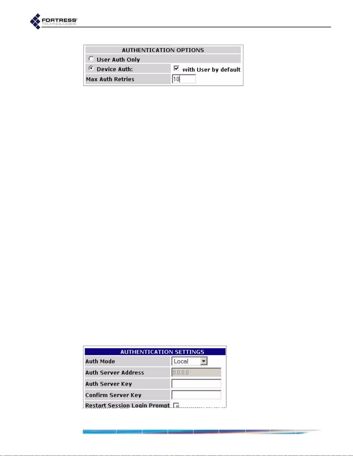
detail:
To configure maximum authentication attempts:
1 Log on to the Bridge GUI admin account and select
SECURITY SETTINGS from the menu on the left.
2 In the AUTHENTICATION SETTINGS frame, in the Auth Mode
field, ensure that
3 Under AUTHENTICATION OPTIONS, in the Max Auth Retries
Local authentication is enabled.
field, enter a whole number between 1 and 255.
4 Click Apply at the bottom of the screen.
A devices that exceeds the maximum allowable retry attempts
to connect to the Bridge-secured network is locked out until the
device’s
State is set to Allowed. Such a device is locked out on
every Bridge in a point-to-multipoint network, and you must
change the device’s
State setting on every Bridge that handles
traffic from the device.
Fortress Bridge: Configuration
Users who exceed the maximum allowable retry attempts to
log on to the Bridge-secured network are locked out until you
reset their sessions.
3.6.6.6 Restart Session Login Prompt
When the
Restart Session Login Prompt is enabled on the
Bridge, the sessions of users whose traffic is passed by that
Bridge timeout at the configured interval, forcing these users’
devices to renegotiate encryption keys and prompting users to
reauthenticate by entering their user names and passwords.
In point-to-point and point-to-multipoint deployments, such a
user would be prompted for his credentials by every Bridge that
passes traffic from that user’s device.
To avoid repeated login prompts for these users, disable
Restart Session Login Prompt on all of the non-root Bridges on
the network. This will allow the user to reauthenticate and the
device to re-key with only the root Bridge.
detail:
45
Page 56
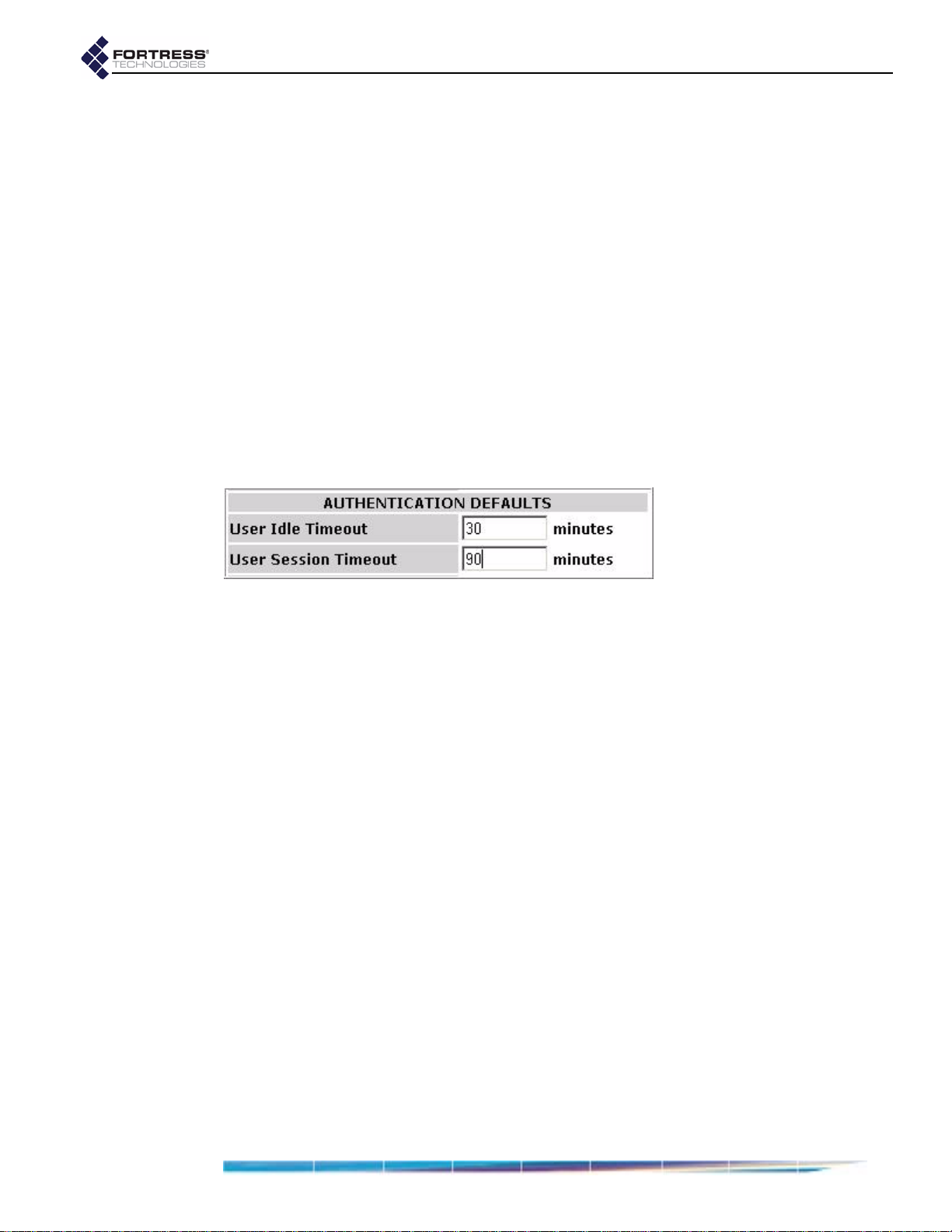
To enable/disable user session timeout login prompts:
1 Log on to the Bridge GUI admin account and select
SECURITY SETTINGS from the menu on the left.
2 In the AUTHENTICATION SETTINGS frame:
Check the box for Restart Session Login Prompt to
enable user session timeout prompts (the default).
or
Clear the checkbox for Restart Session Login Prompt to
disable user session timeout prompts
3 Click Apply at the bottom of the screen.
3.6.6.7 Default User Authentication Settings
The default
Idle Timeout and Session Timeout settings that will
automatically populate the corresponding fields in the
USER frame of the USER AUTHENTICATION screen are configured
on the
settings for users individually (on the
SECURITY SETTINGS screen. You can change these
USER AUTHENTICATION
screen, described in Section 4.2.2).
detail:
Fortress Bridge: Configuration
.
ADD
To configure default idle and session timeouts
for authenticated users:
1 Log on to the Bridge GUI admin account and select
SECURITY SETTINGS from the menu on the left.
2 In the AUTHENTICATION SETTINGS frame, in Auth Mode,
ensure that
3 Under AUTHENTICATION DEFAULTS:
In User Idle Timeout - enter the number of whole
Local authentication is enabled.
minutes, between 1 and 9999, that a user’s device can
be idle on the network before it must renegotiate keys
with the Bridge. Enter zero (0) to disable idle timeouts.
The default setting is 30 minutes.
In User Session Timeout - enter the number of whole
minutes, between 1 and 9999, that a user’s device can
be present on the network before the current session is
ended and the user must log back in to re-establish the
connection. Enter zero (0) to disable session timeouts.
The default setting is 720 minutes.
4 Click Apply at the bottom of the screen.
3.6.6.8 Default Device Authentication Settings
Whether or not user authentication is enabled by default for
new devices automatically populating the
AUTHENTICATION screen is configured on the SECURITY SETTINGS
screen, as is the default
Device State setting they are initially
DEVICE
assigned.
46
Page 57

detail:
To configure the default user authentication and device
state for authenticating devices:
1 Log on to the Bridge GUI admin account and select
SECURITY SETTINGS from the menu on the left.
2 In the AUTHENTICATION SETTINGS frame, in Auth Mode,
ensure that
Local authentication is enabled and that Device
Auth is selected under AUTHENTICATION OPTIONS (refer to
sections 3.6.6.1 and 3.6.6.4, respectively).
Fortress Bridge: Configuration
detail:
3 Under AUTHENTICATION OPTIONS, to the right of Device Auth:
check the box beside with User Auth by default to enable
user authentication for new devices by default. (This is
the default setting.)
or
clear the checkbox beside with User Auth by default to
disable user authentication for new devices by default.
4 Under AUTHENTICATION DEFAULTS, in the Device State field,
select one of:
Allow - the device will be allowed to connect.
Pending - connection requires administrator action
(explicitly changing the device’s
Deny - the device is not allowed on the network.
5 Click Apply at the bottom of the screen.
Auth State to Allow).
NOTE: Yo u c a n
change the user
authentication and de-
vice state settings for
devices individually—
on the
TICATION screen, de-
DEVICE AUTHEN-
scribed in Section 4.1.2.
3.7 Blackout Mode
The BLACKOUT MODE setting on the Fortress Bridge globally
turns the front-panel LEDs on and off.
When
indicators will illuminate for any reason—except for a single,
initial blink (green) of less than half a second, at the beginning
of the boot process.
When
LED indicators function normally.
Front-panel LED behaviors and their associated meanings are
covered in Section 5.6.
BLACKOUT MODE is Enabled, none of the front-panel
BLACKOUT MODE is Disabled (the default), the front-panel
NOTE: When the
Bridge is in black-
out mode, you can tem-
porarily toggle front-
panel LEDs back on—to
use them during front-
panel configuration—by
pressing
SW1 on the
front panel.
47
Page 58

To enable/disable blackout mode:
1 Log on to the Bridge GUI admin account and select SYSTEM
OPTIONS from the menu on the left.
detail:
2 Under BLACKOUT MODE, in the Status field choose to Enable
BLACKOUT MODE (turn the LEDs off) or Disable BLACKOUT
MODE (turn the LEDs on).
3 Click OK in the BLACKOUT MODE frame.
You can also enable/disable blackout mode through the
Bridge’s front-panel switches (refer to Section 3.10.1.2)
3.8 System Date and Time
detail:
Fortress Bridge: Configuration
To change the date and time on the Bridge:
1 Log on to the Bridge GUI admin account and select SYSTEM
OPTIONS from the menu on the left.
2 At the top of the SYSTEM OPTIONS screen, under SET SYSTEM
TIME, enter the time and date, using two-digit values,
according to the format:
3 Click Apply at the bottom of the SET SYSTEM TIME frame.
hh:mm MM:DD:YY.
3.9 Restoring Default Settings
The Fortress Bridge’s factory default configuration settings can
be restored in their entirety through the Bridge CLI (refer to
Section 6.4.7) or via the front-panel switches (refer to Section
3.10.3).
After default settings are restored, the Bridge will have to be
reconfigured for use, just as though it were newly installed, out
of the box.
Because the Bridge’s configuration settings could themselves
be sensitive, Fortress Technologies recommends restoring
them to their default values whenever the Bridge is to be
shipped (or otherwise transported) out of a secured location.
NOTE: The SYSTEM
DATE AND TIME
screen features an info r-
mational timestamp.
The refresh function of
your browser updates
this timestamp.
48
Page 59

3.10 Front-Panel Operation
The Fortress Bridge front panel is equipped with three,
recessed buttons: two switches (labeled
Reset button.
3.10.1 Mode Selection from the Front Panel
The front-panel switches can be used to select the Bridge Mode
of the Bridge’s internal Radio 2 as well as to turn the Bridge’s
front-panel LEDs off and on (enable/disable blackout mode).
Each of these Bridge settings has only two possible values.
Configuring them through the front-panel switches toggles the
setting from its current value to the alternate value.
SW1 and SW2) and a
Fortress Bridge: Configuration
NOTE: Refer to
Section 3.3.1.4 for
more information about
Bridge Mode and to Sec-
tion 3.7 for an explana-
tion of blackout mode.
Figure 3.2. Front-panel buttons
3.10.1.1 Toggling the Bridge Mode Setting on Radio 2
Radio 2 is in
Bridge Radio Mode by default, and its default
Bridge Mode setting is Root.
If this setting is still at its default value, the procedure below will
change the
currently
Root.)
Bridge Mode setting to Non-Root. (If the setting is
Non-Root, the procedure will return the setting to
If Radio 2’s Radio Mode setting has been changed to AP, the
procedure below will still toggle the radio’s
but the new setting will not take effect until the
been set again to
1 Press SW1 and hold it down for five seconds—just until the
upper
Stat1 LED should be flashing slowly (green).
2 While Stat1 is flashing, press and quickly release SW2
Radio LEDs go out, then immediately release it. The
Bridge.
once. Reconfiguration of Radio 2’s
Bridge Mode setting,
Radio Mode has
Bridge Mode setting is
NOTE: Yo u c a n
also change the
Bridge Mode setting in
the Bridge GUI (Section
3.3.1.4) or in the Bridge
CLI (Section 6.4.3).
49
Page 60

indicated by the Stat2 LED, which flashes rapidly (green)
when the new mode is selected.
If you accidentally cycle past the
continue pushing
3 When Stat2 is flashing, press SW1 and hold it down for two
seconds to save the new
and
Stat2 LEDs will stop flashing and light solid green to
SW2 until Stat2 again begins flashing.
Bridge Mode setting. The Stat1
Bridge Mode setting,
indicate that you have successfully changed Radio 2’s
Bridge Mode.
If you skip Step 3, the front-panel configuration operation
will time out after 60 seconds, and the
will remain unchanged.
After you have successfully saved the new setting, the Bridge
will reboot automatically so that the new setting can take effect.
After booting, Bridge LEDs will resume normal operation.
3.10.1.2 Toggling the Blackout Mode setting
The default blackout mode setting is
Disabled, in which state
the Bridge’s front-panel LEDs illuminate to indicate various
conditions on the Fortress Bridge. (Front-panel LED behaviors
and their associated meanings are covered in Section 5.6.)
Fortress Bridge: Configuration
Bridge Mode setting
Enabling blackout mode turns all front-panel LEDs off.
If blackout mode is
Disabled, the procedure below will enable it
(turn off the front-panel LEDs). If the Bridge is already in
blackout mode, the procedure will disable it (turn the frontpanel LEDs back on)
1 Press SW1 and hold it down for five seconds—just until the
upper
Stat1 LED should be flashing slowly (green).
2 While Stat1 is flashing, press and quickly release SW2
Radio LEDs go out, then immediately release it. The
twice. Reconfiguration of the blackout mode setting is
indicated by the
Clr LED, which flashes rapidly (green)
when the new mode is selected.
If you accidentally cycle past the blackout mode setting,
continue pushing
3 When Clr is flashing, press SW1 and hold it down for two
seconds to save the new blackout mode setting. The
Clr LEDs will stop flashing and light solid green to
and
SW2 until Clr again begins flashing.
Stat1
indicate that you have successfully changed the Bridge’s
blackout mode.
If you skip Step 3, the front-panel configuration operation
will time out after 60 seconds, and the blackout mode
setting will remain unchanged.
After you have saved the change, Bridge LEDs will either
resume their normal operation (
go completely dark (
BLACKOUT MODE: Enabled), according to
BLACKOUT MODE: Disabled), or
the new setting.
NOTE: Yo u c a n
also change the
BLACKOUT MODE setting in
the Bridge GUI (Section
3.7) or in the Bridge CLI
(Section 6.4.5.9).
NOTE: When the
Bridge is in black-
out mode, you can tem-
porarily toggle front-
panel LEDs back on—to
use during further
front-panel configura-
tion—by pressing SW1.
50
Page 61

3.10.2 Rebooting the Bridge from the Front Panel
To reboot the Fortress Bridge from the front-panel:
Fortress Bridge: Configuration
1 Press and hold the Reset button for one second, until the
Stat1 LED exhibits a slow green flash to indicate that the
Bridge is rebooting.
2 Release the button.
After the Bridge reboots the
Stat1 LED will again light solid
green.
3.10.3 Restoring Defaults from the Front Panel
To restore the Bridge’s configuration settings to their factorydefault values:
1 Press and hold SW1.
2 Still holding SW1, press and hold SW2 for 10 seconds.
All LEDs will flash fast (green) to indicate that factory
default settings will be restored.
3 Hold both switches down for another 10 seconds, until all
LEDs light solid green.
If you release the switches before the LEDs light solid
green, the operation is cancelled and settings will remain
unchanged.
4 Release both switches.
After you have successfully initiated the restore operation, the
Bridge will reboot automatically.
NOTE: There are
no LED indica-
tions in a Bridge in
blackout mode (refer to
Section 3.7).
NOTE: Yo u c a n
also restore the
Bridge’s factory default
settings from the Bridge
CLI (Section 6.4.7).
After booting, the Bridge LEDs will resume normal operation
and all configuration settings, including the IP address of the
Bridge’s management interface will be at their factory-default
values.
51
Page 62

Chapter 4 Administration
4.1 Device Authentication
Fortress Bridge: Administration
Device authentication is supported only for Local
authentication. (When
External authentication is selected, the
settings that configure device authentication are grayed out to
reflect your selection.)
On a Fortress-secured network with device authentication
enabled, a unique
Device ID is generated for each device
connecting from an encrypted zone. The Device ID is
subsequently used to authenticate that device on the network.
The Fortress Bridge has an internal RADIUS (Remote
Authentication Dial-In User Service) server built-in. The Bridge
additionally supports external RADIUS servers.
Authentication (device and user) is enabled and disabled
globally on the Bridge by selecting
on the
SETTINGS screen. Device authentication can be enabled only
when
AUTHENTICATION SETTINGS frame of the SECURITY
Local authentication is selected.
Disabled, Local or External
When device authentication is enabled, the Bridge detects
devices attempting to access the Bridge’s encrypted zone and
lists them on the
DEVICE AUTHENTICATION screen.
Device authentication is globally enabled—for Bridge’s
configured for
selection made in
SETTINGS screen.
Local authentication—when it is included in the
AUTHENTICATION OPTIONS on the SECURITY
For any given device, device authentication can be used by
itself or combined with the Bridge’s provisions for user
authentication.
NOTE: The Bridge
supports 802.1X
authentication through
separate and unrelated
configuration settings.
These are described in
802.1X Security (for
wireless devices) and in
Section 3.4, 802.1X Serv-
er and LAN Port Settings.
NOTE: Refer to
Section 3.6.6.1 for
instructions on globally
enabling authentication
and to Section 3.6.6.4 for
instructions on globally
enabling device authen-
tication and configur-
ing devices’ default user
authentication option.
4.1.1 Maximum Device Authentication Retries
The maximum number of unsuccessful authentication attempts
a device will be allowed before ending its session is also
configured globally; the same setting configures the maximum
number of times users can unsuccessfully attempt to
52
Page 63

authenticate on the network. (Refer to Section 3.6.6.5 for
detailed instructions.)
If a device exceeds the maximum allowable retry attempts to
connect to the Bridge-secured network, that device will be
locked out until the device’s
State is set to Allow. Such a device
is locked out on every Bridge in a point-to-multipoint network,
and you must change the device’s
State setting on every Bridge
that handles traffic from the device.
4.1.1 Default Device Authentication Settings
As devices auto-populate the DEVICE AUTHENTICATION screen,
they are permitted or denied immediate access to the network
based on the default
AUTHENTICATION SETTINGS frame of the SECURITY SETTINGS
screen (under
AUTHENTICATION DEFAULTS).
Device State setting, located in the
Fortress Bridge: Administration
Another default setting in the AUTHENTICATION SETTINGS frame
determines whether user authentication is included by default
for devices auto-populating the
DEVICE AUTHENTICATION screen.
Whatever default settings you choose for authenticating
devices, you can change the initial
AUTHENTICATION OPTIONS settings individually for any device on
the
DEVICE AUTHENTICATION screen.
Device State and
4.1.2 Individual Device Authentication Settings
Devices will auto-populate the DEVICE AUTHENTICATION screen
only when device authentication is enabled in the
AUTHENTICATION SETTINGS frame of the SECURITY SETTINGS
screen (refer to Section 3.6.6, Non-802.1X Authentication
Global and Default Settings).
NOTE: Refer to
Section 3.6.6.8 for
detailed instructions on
configuring the default
device state and user
authentication option
settings for new devices.
The Fortress Bridge tracks and manages access for devices on
the Fortress-secured network through two identifiers, which are
not user-configurable:
Device ID - a unique, 16-digit hexadecimal identifier
generated for the device and used to authenticate it on the
network
Device MAC - the device’s MAC address
53
Page 64

Fortress Bridge: Administration
Access user configurable settings for an authenticating device
by clicking its
Edit button under AUTHORIZED DEVICES (Section
4.1.2.1). Configurable settings include:
Device Name - accepts up to 64 alphanumeric characters
by which you can identify the device.
If a device has a hostname associated with it (the
hostname of a laptop running the Fortress Secure Client,
for instance), that hostname is included for the device when
it is first added to the
DEVICE AUTHENTICATION screen. If no
hostname is associated with the device, it will be added
without one.
Auth Option - configures whether the Bridge will additionally
require user authentication before allowing the device to
connect to the encrypted zone.
If you enabled
settings under
their defaults, devices auto-populate the
DEVICES list with the user authentication option.
Auth State - configures the initial state of the device’s
Local authentication while leaving the
AUTHENTICATION OPTIONS (Section 3.6.6.8) at
AUTHORIZED
connection to the encrypted zone:
Allow - the device will be allowed to connect.
Pending - connection requires administrator action:
Change the device’s
If you enabled
settings under
Auth State to Allow.
Local authentication while leaving
AUTHENTICATION DEFAULTS (Section
3.6.6.8) at their defaults, devices auto-populate the
AUTHORIZED DEVICES list a State of Pending.
Deny - the device is not allowed on the network.
4.1.2.1 Editing a Device
You can edit an existing hostname or add one for a device that
has no hostname. You can also reconfigure any individual
device’s
Auth Option and Auth State.
To edit a device:
1 Log on to the Bridge GUI admin account and choose DEVICE
AUTHENTICATION from the menu on the left.
54
Page 65
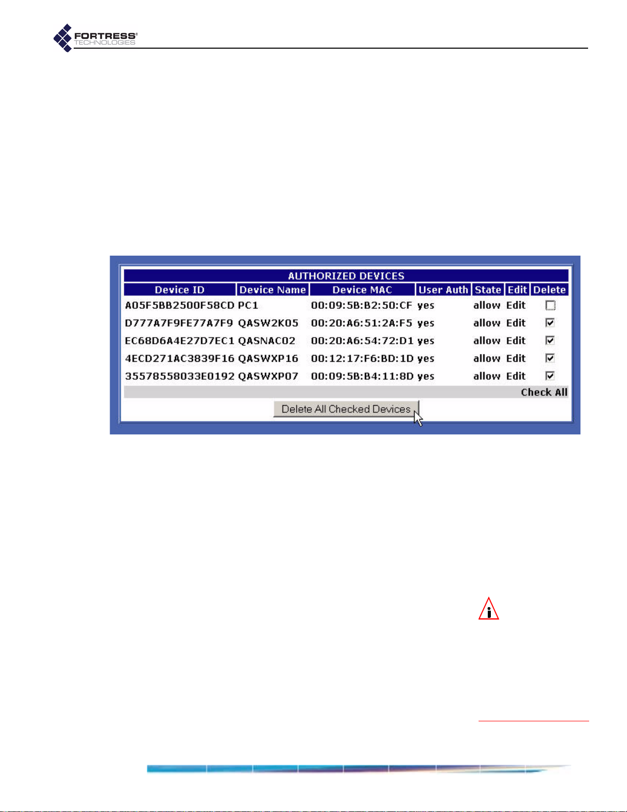
2 On the DEVICE AUTHENTICATION screen, click the Edit button
of the device for which you want to change settings.
3 In the EDIT DEVICE frame (above the device list) where the
device’s current settings are displayed, enter new values
into the relevant fields (described in Section 4.1.2).
4 Click Update to save the edited settings (or Cancel your
changes).
The device’s entry in
changes.
4.1.2.2 Deleting Devices
You can delete one device, multiple devices or all devices from
device authentication.
Fortress Bridge: Administration
AUTHORIZED DEVICES reflects your
To delete one or more devices:
1 Log on to the Bridge GUI admin account and choose DEVICE
AUTHENTICATION from the menu on the left.
2 On the DEVICE AUTHENTICATION screen, in the AUTHORIZED
DEVICES display, place a check in the box(es) in the Delete
column for the device(s) you want to delete, or click
All below the column to select all devices for deletion.
3 Click Delete All Checked Devices.
The device(s) you selected will be removed from the
AUTHORIZED DEVICES display.
4.2 User Authentication
You can configure default and individual user authentication
parameters through the Bridge only when
is selected. (When
settings are configured on the external authentication server.)
The Fortress Bridge has an internal RADIUS (Remote
Authentication Dial-In User Service) server built-in. The Bridge
additionally supports external RADIUS servers.
Authentication (device and user) is enabled and disabled
globally on the Bridge by selecting
External authentication is selected, these
Check
Local authentication
Disabled, Local or External
NOTE: The Bridge
supports 802.1X
authentication through
separate and unrelated
configuration settings.
These are described in
802.1X Security (for
wireless devices) and in
Section 3.4, 802.1X Serv-
er and LAN Port Settings.
55
Page 66

Fortress Bridge: Administration
on the AUTHENTICATION SETTINGS frame of the SECURITY
SETTINGS screen.
On a Fortress Bridge-secured network, user authentication can
be used by itself or combined with device authentication. The
options that determine whether device authentication is
enabled are also configured globally, in the
SETTINGS frame of the SECURITY SETTINGS screen.
AUTHENTICATION
4.2.1 Maximum User Authentication Retries
The maximum number of unsuccessful authentication attempts
a user will be allowed before being locked out is another global
setting; the same setting configures the maximum number of
times devices can unsuccessfully attempt to authenticate on
the network. (Refer to Section 3.6.6.5 for detailed instructions.)
If a user exceeds the maximum allowable retry attempts to log
on to the Bridge-secured network, s/he will be locked out until
you reset the session.
4.2.1 Default User Authentication Settings
While idle timeout and session timeout settings can be
individually configured for each user, the default values for
these settings are determined by the
set in the
SETTINGS screen.
AUTHENTICATION SETTINGS frame of the SECURITY
AUTHENTICATION DEFAULTS
4.2.2 Individual User Authentication Settings
User authentication on the Fortress Bridge requires the usual
settings to identify, track and manage access for each user on
the Fortress-secured network:
NOTE: Refer to
Section 3.6.6.1 and
for instructions on glo-
bally enabling
thentication and to
Section 3.6.6.4 for in-
structions on enabling
device authentication.
NOTE: Refer to
Section 3.6.6.7 for
detailed instructions on
configuring default user
authentication settings.
Local au-
Username - identifies the user on the network—from 1 to 16
alphanumeric characters—required.
Full Name - associates the person, by name, with his/her
user account—up to 64 alphanumeric characters, including
spaces, dashes, dots and underscores—optional.
Password/Verify Password - establishes the credentials the
user must key in to access his/her user account—from 4 to
16 alphanumeric characters, including shifted numeral-key
symbols—required.
Idle Timeout - sets the amount of time the user’s device can
be idle on the network before it must renegotiate keys with
the Bridge.
Idle Timeout is set in minutes, between 0 and 9999. A value
of zero disables idle timeout for that user (his device can be
idle indefinitely without timing out). If you enabled
Local
authentication while leaving the settings under
AUTHENTICATION DEFAULTS (Section 3.6.6.7) at their
defaults, the
Idle Timeout value in the ADD USER frame will
be at 30 minutes.
56
Page 67
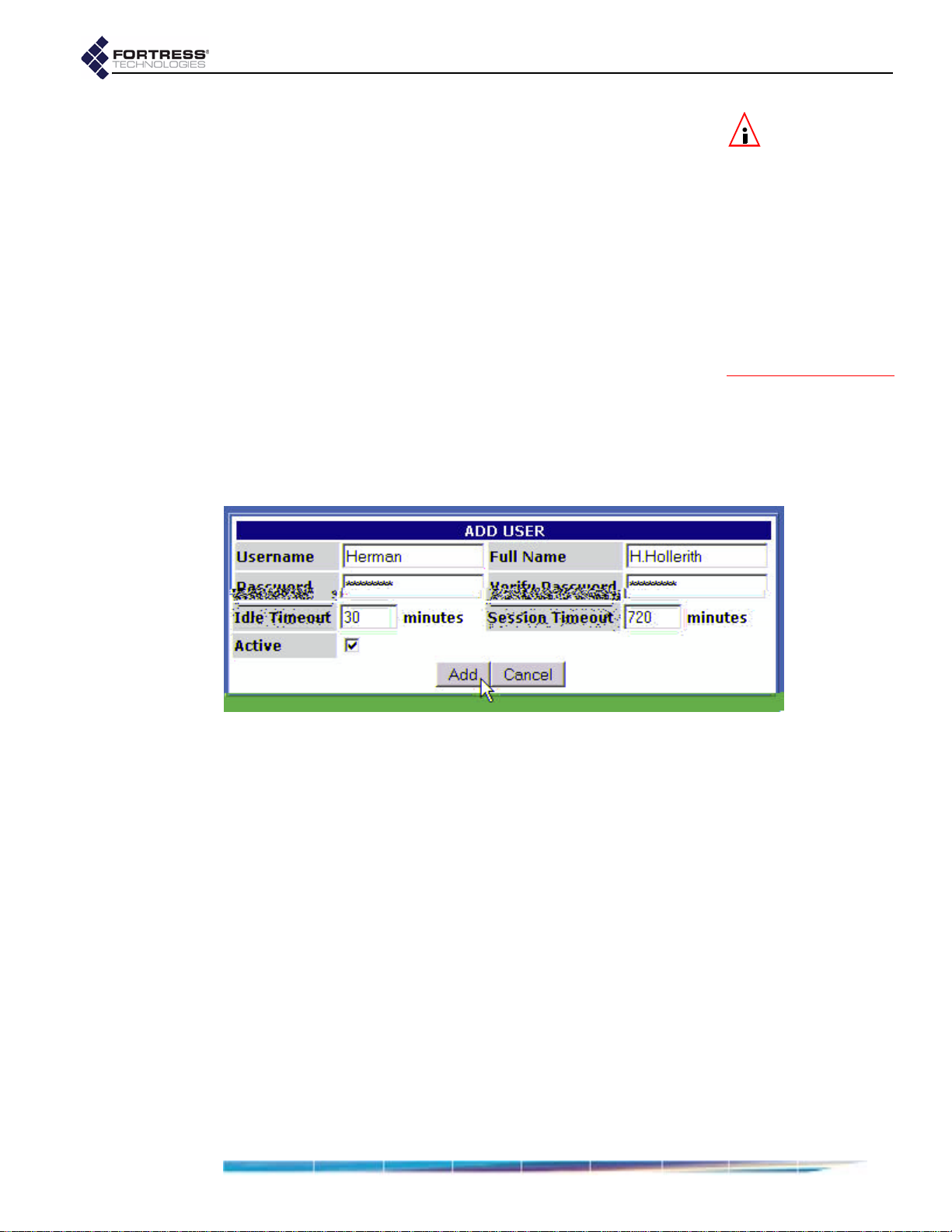
Fortress Bridge: Administration
Session Timeout - sets the amount of time the user’s device
can be present on the network before the current session is
ended and he/she must log back in to re-establish the
connection.
Session Timeout is set in minutes, between 0 and 9999. A
value of zero disables session timeout for that user (her
device can be present on the network indefinitely without
timing out). If you enabled
leaving the settings under
(Section 3.6.6.7) at their defaults, the
value in the
Active - enables/disables user access to the account.
A check in the box enables the account (the default);
clearing the checkbox disables it.
4.2.2.1 Adding a User
New user accounts can only be created on the Bridge when
Local authentication is globally enabled (refer to Section 4.2,
above).
Local authentication while
AUTHENTICATION DEFAULTS
Session Timeout
ADD USER frame will be at 720 minutes.
NOTE: In point-to-
point/multipoint
deployments, Fortress
recommends that you
disable the
sion Login Prompt
ers on all non-root
Bridges on the network,
so that, when users’ ses-
sions time out, they are
prompted for their cre-
dentials by only the root
Bridge. Refer to Section
3.6.6.6 guidance.
Restart Ses-
for us-
To add a user:
1 Log on to the Bridge GUI admin account and choose USER
AUTHENTICATION from the menu on the left.
2 On the USER AUTHENTICATION screen, in the ADD USER
frame, enter valid values into the relevant fields (described
above).
3 Click Add to save the new user account (or Cancel the
addition).
The
USER ACCOUNTS frame shows the user you have
added, with the settings you specified.
4.2.2.2 Editing a User Account
Once configured,
Username cannot be changed. You can only
delete a user’s account and create a new account with a new
Username. You can edit any other value associated with a user
account.
To edit a user account:
1 Log on to the Bridge GUI admin account and choose USER
AUTHENTICATION from the menu on the left.
57
Page 68

Fortress Bridge: Administration
2 On the USER AUTHENTICATION screen, click the Edit button of
the user for which you want to change settings.
3 In the EDIT USER frame (above USER ACCOUNTS) where the
account’s current settings are displayed, enter new values
into the relevant fields (described in Section 4.2.2).
4 Click Update to save the edited settings (or Cancel your
changes).
The user’s entry in
USER ACCOUNTS reflects your changes.
4.2.2.3 Deleting a User Account
You can delete a user account at any time. Alternatively, you
can edit a user account to be temporarily inactive—by clearing
Active checkbox—reactivating the account at a later date
the
(refer to Section 4.2.2.2, above).
To delete a user account:
1 Log on to the Bridge GUI admin account and choose USER
AUTHENTICATION from the menu on the left.
2 On the USER AUTHENTICATION screen, click the Delete button
of the user you want to delete.
3 Click OK in the confirmation dialog (or Cancel the deletion).
The user you deleted will be removed from the
ACCOUNTS display.
USER
58
Page 69

4.3 Trusted Devices
Some wireless devices—IP phones, digital scales or printers,
and APs, for example—are not equipped to run additional
software such as the Fortress Secure Client. In order to allow
such a device access to the encrypted zone, the Fortress
Bridge must be configured to identify it as a
which the narrowest possible access rules should be applied.
All traffic to and from Trusted Devices is sent in the clear
(unencrypted).
Fortress Bridge: Administration
T rusted Device—to
Once its status as a Trusted Device has been configured, the
Bridge uses the settings you establish for it to identify, track
and manage access for the device on the network. These are:
TD Identifier - accepts up to twelve, alphanumeric
characters to uniquely identify the Trusted Device.
IP Address - establishes the device’s IP address—or, by
entering the word
any, configures the Trusted Device to
accept any IP address, as provided by the network DHCP
(Dynamic Host Configuration Protocol) server.
MAC Address - establishes the device’s MAC address.
Port Number(s) - specifies the port numbers through which
the Trusted Device can access the encrypted zone—or, by
entering the word
any, configures access for the device
through any port.
For reference, the screen displays commonly used port
numbers to the right of the configuration fields.
When one or more Trusted Devices are configured on the
Fortress Bridge, the Bridge will continually signal—through the
flashing green, front-panel cleartext LED (labeled
cleartext is being passed on the network.
While the cleartext
Clr)—that
signal occurs in either operating mode, in FIPS terminology, it
indicates that the Bridge is in
Bypass Mode (BPM)
NOTE: Tr u s t e d D e -
vices must be
uniquely named on the
Bridge. An error mes-
sage will result if you at-
tempt to add a Trusted
Device with a name al-
ready in use.
CAUTION: Specify-
ing that
can access a TD can
pose a significant secu-
rity risk.
any
port
4.3.1 Adding Trusted Devices
Trusted Devices are added one at a time.
To add a Trusted Device:
1 Log on to the Bridge GUI admin account and choose
TRUSTED DEVICES from the menu on the left.
2 On the TRUSTED DEVICES screen, in the ADD TRUSTED DEVICE
frame, enter valid values into the relevant fields (described
above).
3 Click Add to save the new Trusted Device (or Cancel the
addition).
CAUTION: Net-
work security is
maximized when the
smallest possible num-
ber of Trusted Devices
are configured and the
smallest effective set of
ports is specified for
each.
59
Page 70
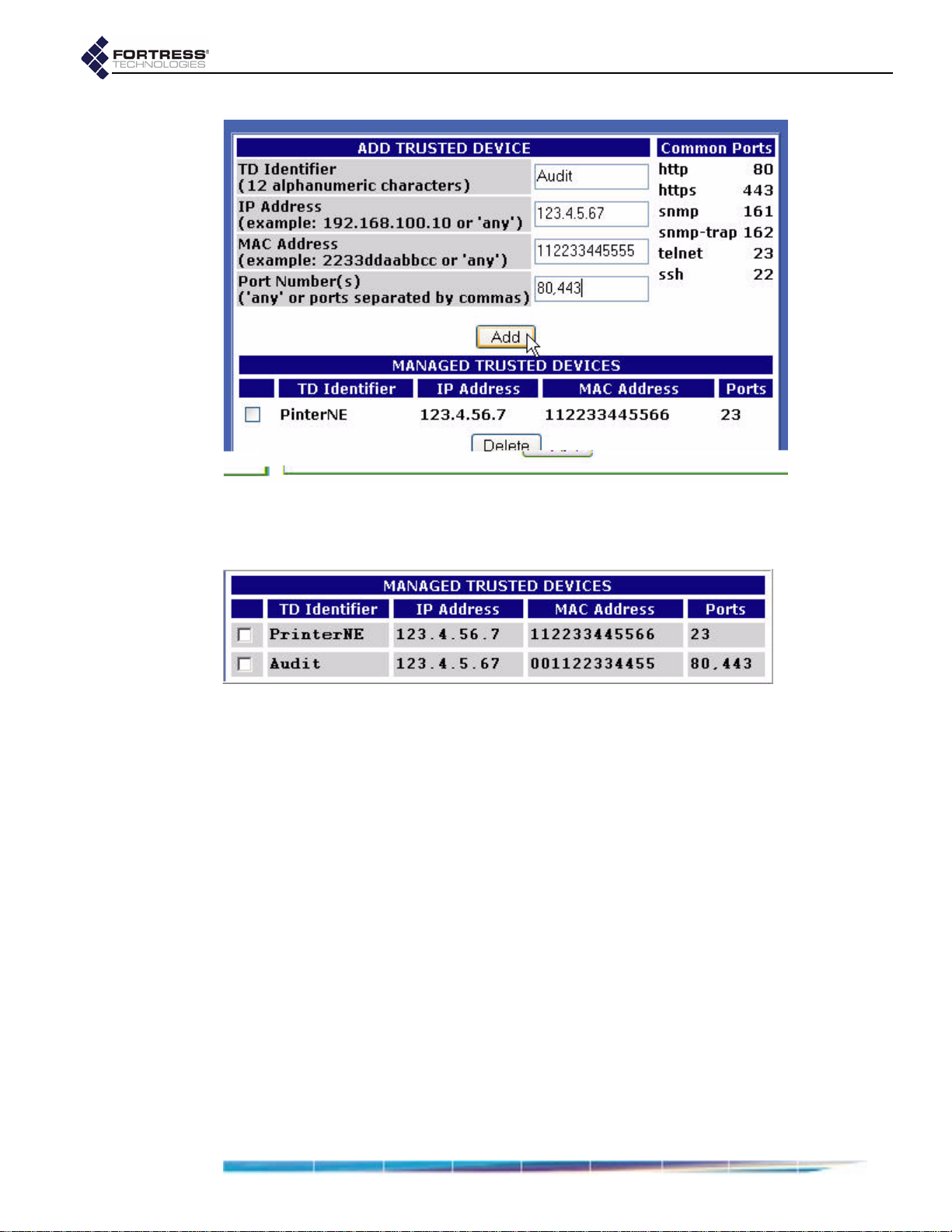
Fortress Bridge: Administration
The section of the frame under MANAGED TRUSTED DEVICES
shows the Trusted Device you added, with the settings you
specified.
detail:
4.3.1 Editing Trusted Devices
You can edit the IP and MAC addresses of an existing Trusted
Device and change its port settings, but you cannot change its
TD Identifier. To edit a Trusted Device:
1 Log on to the Bridge GUI admin account and choose
TRUSTED DEVICES from the menu on the left.
2 On the TRUSTED DEVICES screen, under MANAGED TRUSTED
DEVICES, click the TD Identifier of the device for which you
want to change the settings.
3 In the resulting EDIT TRUSTED DEVICE dialog, enter valid
values into the relevant fields (described above).
4 Click OK to save the new settings (or Cancel your changes).
The Trusted Device’s entry under
DEVICES reflects your changes.
MANAGED TRUSTED
60
Page 71
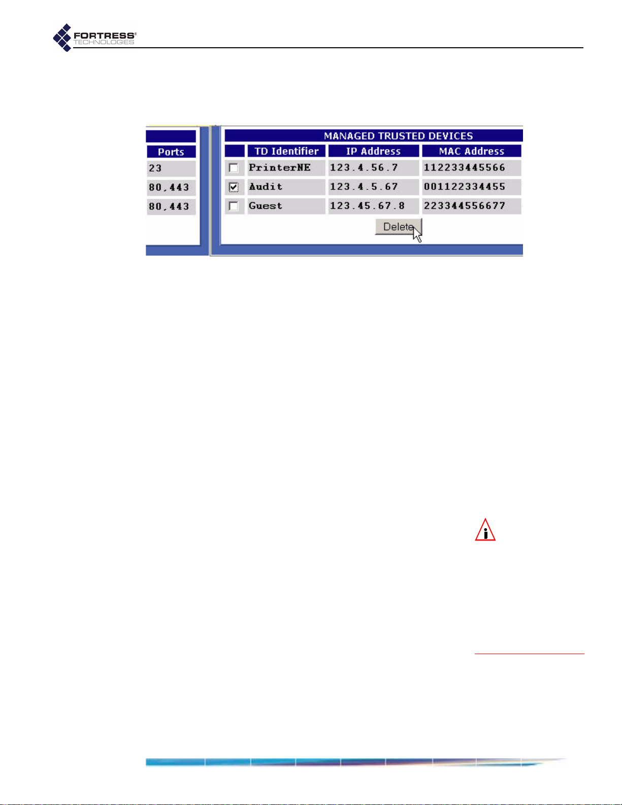
4.3.2 Deleting Trusted Devices
You can delete Trusted Devices one at a time, or by selecting
multiple devices for deletion.
detail:
1 Log on to the Bridge GUI admin account and choose
TRUSTED DEVICES from the menu on the left.
2 On the TRUSTED DEVICES screen, in the MANAGED TRUSTED
DEVICES frame, check the box(es) beside the Trusted
Device(s) you wish to delete and click
of the frame.
The selected Trusted Device(s) will be removed from list of
MANAGED TRUSTED DEVICES.
Fortress Bridge: Administration
Delete at the bottom
4.3.3 Visitor Access through Trusted Devices
Visitors using their own mobile devices at your facilities can be
granted temporary access to the WLAN by configuring Trusted
Device access for their devices, with appropriately limited port
access.
Trusted Devices for visitors are managed no differently from
other Trusted Devices.
4.4 SNMP Settings
The Fortress Bridge can be configured for monitoring through
SNMP (Simple Network Management Protocol) versions 1 and
2. The Fortress MIB (management information base) is
included on the Bridge CD and available from:
https://www.fortresstech.com/support/products_updates.asp
SNMP monitoring is configured through these settings:
SNMP - determines whether SNMP is Enabled or Disabled
on the Bridge, according to your selection on the dropdown.
System Location - identifies the Fortress Bridge.
System Contact - specifies the E-mail address to which
SNMP notifications are sent.
Read Only Community - identifies the SNMP read-only
community.
Read/Write Community - identifies the SNMP read/write
community.
NOTE: You cannot
configure SNMP
monitoring on a For-
tress Bridge in
.
erating mode (the
default). Refer to Sec-
tion 3.6.1 for more infor-
mation about Bridge
operating modes and to
Section 6.4.5.5 for de-
tails on changing it.
FIPS op-
61
Page 72

4.4.1 Configuring SNMP
1 Log on to the Bridge GUI admin account and choose SNMP
SETTINGS from the menu on the left.
2 In the SNMP OPTIONS frame, enter valid values into the
relevant fields (described above).
3 Click Apply.
Fortress Bridge: Administration
4.5 Backing Up and Restoring
The backup function of the Bridge creates and downloads a
configuration file that can be used to restore those Bridge
settings it saves. You can create multiple backup files under
pathnames of your choosing.
Table 4.1 shows those configuration settings that are saved to,
and so will be restored from, a backup file.
Because recording them could pose a security risk, no
passwords are backed up. In order to maintain network
security, after restoring from a backup file all passwords must
be reset for each of the Bridge’s password-protected accounts:
Bridge GUI admin and operator accounts
Bridge CLI account
Fortress Technologies recommends backing up your Bridge
configuration:
when you first set up the Bridge
immediately before you upgrade Bridge software or make
significant configuration changes
after you have tested significant configuration changes and
they have proved fully operational
NOTE:
The
Bridge
Mode
setting, which
determines whether a
Fortress Bridge in bridge
mode will act a root or a
non-root node, is not
backed up.
62
Page 73

Table 4.1. User Configured Settings Backed Up for the Bridge
function setting
network
STP enable/disable
WAN port encrypted/unencrypted
radio state enable/disable
radio band (Radio 1) 802.11g/802.11a
radio mode AP/Bridge
channel
transmit power
radios
distance
preamble
beacon interval
multicasting enable/disable
LED RSSI monitor enable/disable
VAP SSIDs and related settings
any created Wireless Extension Tools scripts
802.1X authentication server settings
802.1X
authentication
LAN ports 1–8 802.1X off/on
VAP
Security Suite settings
Access ID
encryption algorithm
a
a
re-keying interval
security
operating mode FIPS/Normal
blackout mode enable/disable
encrypted zone cleartext enable/disable
data compression enable/disable
SSH access on/off
global authentication enable/disable
local authentication server
- or -
external server IP address
non-802.1X
authentication
authentication server key (local or external)
if local authentication:
device and user databases
restart session login prompt enable/disable
system location
SNMP
system contact
read-only community
ID
Trusted Devices
IP address
MAC address
accessible ports
a. The Access ID and encryption algorithm are not backed up for a Bridge in
FIPS operating mode.
Fortress Bridge: Administration
63
Page 74

4.5.1 Backing Up the Bridge Configuration
1 Log on to the Bridge GUI admin account and choose
SYSTEM OPTIONS from the menu on the left.
2 On the SYSTEM OPTIONS screen under BACKUP SYSTEM
SETTINGS, click Next.
detail:
3 On the resulting screen:
Optionally enter a Password to protect the backup file.
Click Backup (or Cancel the operation).
Fortress Bridge: Administration
NOTE: If you
choose to pass-
word-protect the back-
up file, remember that
the password will be re-
quired in order to re-
store from the file.
4 On the system dialog, choose to save the file to disk. The
file is named
.gz extension to the filename.) You can save it to any
a
settings.fti by default. (Windows® may appe nd
location and rename it if you choose.
4.5.2 Restoring from a Backup File
Keep in mind that the restore operation restores only those
settings present in the backup file, as described in Section 4.5.
1 Log on to the Bridge GUI admin account and choose
SYSTEM OPTIONS from the menu on the left.
2 On the SYSTEM OPTIONS screen under RESTORE SYSTEM
SETTINGS, click Next.
detail:
3 On the resulting screen:
Enter or browse to the pathname of the backup file.
If the backup file is password-protected enter the
Password.
Click Restore (or Cancel the operation).
The GUI informs you
restored and advises that you must reboot the system in
order for the settings to take effect.
4 Click OK to clear the system dialog.
5 Follow the instructions in Section 4.7.
6 After you have rebooted the Bridge, change all three Bridge
account passwords from their defaults, according to the
instructions in Section 3.5 and Section 6.4.4.2,
respectively.
The settings have been successfully
CAUTION: The re-
store operation
overwrites existing set-
tings with those in the
backup file (shown in
Table 4.1) , including lo-
cal device and user au-
thentication databases.
CAUTION: Restor-
ing from a backup
file causes all passwords
to revert to their default
values. The WLAN is
not secure until you
change all three Bridge
account passwords
from their defaults.
64
Page 75
4.6 Software Versions and Upgrades
Fortress Technologies regularly releases updated versions of
the Bridge software that add new features, improve
functionality and/or fix known bugs. Upgrade files may be
shipped to you on CD-ROM or, more often, made available for
download from your account on the Fortress Technologies
website.
www.fortresstech.com/support/products_updates.asp
The Fortress Bridge is compatible with Fortress Secure Client
versions 2.4 and higher. Fortress reco mmends that the Secure
Clients of the Bridge be upgraded to the most recent version of
the Secure Client software available for their respective
platforms and appropriate to your environment.
Fortress Bridge: Administration
4.6.1 Viewing
Current Software Version
The version of the firmware currently running on the Fortress
Bridge is displayed on the
DIAGNOSTICS screen, as well as on
every help screen. To view the current software version:
1 Log on to the Bridge GUI admin account and choose HELP
from the menu on the left.
2 Observe the version information at the top of the screen.
detail:
Alternatively:
1 Log on to the Bridge GUI admin account and choose
DIAGNOSTICS from the menu on the left.
2 Observe the version information at the top of the frame.
4.6.2 Upgrading Bridge Software
If necessary, download the upgrade file from Fortress
Technologies web site (at the address given above).
1 Log on to the Bridge GUI admin account and choose
SYSTEM OPTIONS from the menu on the left.
2 On the SYSTEM OPTIONS screen under UPGRADE SYSTEM
SOFTWARE, click Next.
detail:
3 On the resulting screen:
Enter or browse to the pathname of the upgrade file.
In Password enter the default upgrade file password
fortress.
65
Page 76

Click Apply (or Cancel the operation).
4 Click OK on the system confirmation dialog.
The frame displays
indicate system activity), then changes to the
upgrade...
status display, which presents a series of
Uploading file... (with crawling dots to
Performing
progress messages. When the process completes, the
frame displays [
DONE], and a system dialog prompts you to
reboot the Bridge.
Fortress Bridge: Administration
5 Click OK on the system prompt.
6 Follow the instructions in Section 4.7, below.
66
Page 77

4.7 Rebooting the Bridge
The reboot option power cycles the Bridge, ending all sessions
and forcing Secure Client devices (and any other Fortress
Bridges) in communication with the Bridge to re-key in order to
start a new session.
1 Log on to the Bridge GUI admin account and choose
SYSTEM OPTIONS from the menu on the left.
2 On the SYSTEM OPTIONS screen under REBOOT SYSTEM, click
OK.
detail:
Fortress Bridge: Administration
3 On the resulting system dialog, click OK again (or Cancel the
reboot).
The Bridge emits a short chirp and its front-panel LEDs
light briefly and then go briefly dark, as the Bridge begins
the boot process.
Stat1 LED exhibits a slow green flash
when the LEDs come back on. Then the Bridge, running
the upgraded firmware, returns to normal operation (the
Stat1 LED lights solid green).
You can reboot the Bridge from the front panel (described in
Section 3.10.2), from the Bridge CLI (described in Section
6.5.4), or from the Bridge GUI (described above).
Several configuration changes on the Bridge require a reboot
in order to take effect. Software upgrades require you to
reboot, as well. You will also need to reboot the Bridge to apply
network configuration changes, and you may want to do so as
part of a troubleshooting operation.
NOTE: Beyond the
initial blink at the
beginning of the boot
process, there are no
LED indications in a
Bridge in blackout
mode (refer to Section
3.7).
67
Page 78

Chapter 5 Monitoring and Diagnostics
5.1 Statistics
The statistics screen displays statistics for overall encryptedzone traffic, each of the Bridge’s logical interfaces (including
physical Ethernet ports and all configured virtual radio
interfaces), as well as for each of the Bridge’s internal radios.
Fortress Bridge: Monitoring and Diagnostics
68
Page 79

5.1.1 Traffic Statistics
The packets that the Fortress Bridge has transmitted to and
received from the encrypted zone since cryptographic
processing was last started are shown in the
Encrypt - encrypted packets—the packets received from
the unencrypted zone, encrypted, and then transmitted to
the encrypted zone
Decrypt - decrypted packets—the packets received from
the encrypted zone, decrypted, and then transmitted to the
unencrypted zone
SendClear - cleartext packets received from Trusted
Devices and sent to the unencrypted zone
RcvClear - received clear—cleartext packets received from
Trusted Devices in the encrypted zone
KeyPackets - valid key exchange packets
BadKeys - bad key packets—malformed key exchange
packets
BadDecrypt - key packets the Bridge was unable to decrypt
Bad Packets - malformed packet received (Packets can be
malformed for a number of reasons, such as version
incompatibility or a failed hash check.)
Fortress Bridge: Monitoring and Diagnostics
STATISTICS frame:
5.1.2 Interface Statistics
The DIAGNOSTICS screen displays a MAC address and statistics
for each of the Bridge’s physical and virtual interfaces:
The lan1–8 interfaces correspond to the ports of the
internal LAN switch.
The wan1 interface identifies the Bridge’s WAN port.
Radio 1 is the Bridge’s internal tri-band, 802.11a/b/g radio,
the primary interface for which is labeled Radio 1 VAP 1.
Up to three additional SSIDs are optional and can
configured only on a radio with a Radio Mode setting of
AP (Section 3.3.1.3). When configured, the virtual
interfaces to which the additional SSIDs correspond are
numbered VAP 2, VAP 3 and VA P 4.
Radio 2 is the internal 802.11a, radio, the primary interface
for which is labeled Radio 2 VAP 1.
Up to three additional SSIDs are optional and can
configured only on a radio with a Radio Mode setting of
AP (Section 3.3.1.3). When configured, the virtual
interfaces to which the additional SSIDs correspond are
numbered VAP 2, VAP 3 and VA P 4.
INTERFACE STATISTICS provides a set of three values for each
interface’s receive (RX) and transmit (TX) functions:
69
Page 80

BYTES - the total number of bytes received/transmitted on
the interface
PACKETS - the total number of packets received/transmitted
on the interface
ERRORS - the total number of receive/transmit errors
reported on the interface
5.1.3 Radio Statistics
RADIO 1 is the tri-band, 802.11a/b/g radio and RADIO 2 is the
higher-gain 802.11a radio.
Signal Strength is measured in real time, in decibels
referenced to milliwatts, and displayed as a dynamic value in
RADIO STATISTICS frame of the INTERFACE STATISTICS
the
SCREEN.
The Signal Strength for a radio with a Radio Mode setting of
Bridge can be static or changing, according to the network
deployment. In a point-to-point deployment, the signal level
being measured is from the only other Bridge in the
deployment, and so it remains constant. In a point-to-multipo int
deployment, the Bridge displays the strength of the signal from
each of the other Bridges in the deployment in rotation, at onesecond intervals.
Fortress Bridge: Monitoring and Diagnostics
5.2 Tracking
The Bridge tracks devices in the encrypted zone, including
other Fortress Bridges, any configured Trusted Devices, and
Secure Clients.
The TRACKING screen displays:
MAC Address - the Media Access Control address of the
connected device
Client ID - the Device ID of the connected device, if the
connected device is another Fortress controller device or is
running the Secure Client
State - the state of the device’s connection to the Bridge-
secured network (see Table 5.1, below)
User Name - the user name associated with the device, if a
user is locally configured for the device (This field is absent
when authentication is globally
External authentication is selected.)
IP Address - the network address of the device, or 0.0.0.0,
if the device has been configured to accept
(from the networks DHCP server)
Computer Name - the hostname of the device on which the
Secure Client is running, if the connected device is another
Fortress controller device or is running the Secure Client
(and has a hostname configured)
Disabled on the Bridge or
any IP address
NOTE: The
Bridge’s
screen does not display
the Devi ce ID an d IP ad-
dresses of devices on a
LAN secured by anoth-
er Fortress controller
device. All such devices
display the IP address
and Device ID of the
controller device secur-
ing them. The MAC ad-
dresses of these devices
display accurately.
Tracking
70
Page 81

Fortress Bridge: Monitoring and Diagnostics
Idle Since - the number of hours, minutes and seconds
since the device was last active on the network.
71
Page 82

Table 5.1. Commonly Seen Tracking State Codes
State Meaning
00 new partner not in database
01 static key exchange start
03 static key exchange complete
04 dynamic key exchange start
06 dynamic key exchange complete: secure connection
08 unsecure connection
13 user authentication
15 maximum retries exceeded: locked out
Each device entry on the TRACKING screen is preceded by a
checkbox that, when checked, resets the network session of
that device when
Reset Checked Sessions (at the bottom of the
screen) is clicked.
5.3 AP Associations
Fortress Bridge: Monitoring and Diagnostics
The AP Associations screen provides information about
devices currently connected through the Bridge’s wireless
interfaces.
Radio - shows whether the device is connected through
Radio 1 or Radio 2.
VAP - varies according to the if the Radio Mode setting:
If the radio through which the device is connected has a
Radio Mode setting of
AP: indicates which of the radio’s
virtual access point (VAP) interfaces the device is
associated with, by number.
If the radio through which the device is connected has a
Radio Mode of
Bridge: VAP displays WDS (wireless
distribution system) to indicate that the connected device is
another Fortress Bridge in a point-to-point/multipoint
deployment. (Refer to Section 3.3.1.3 for more information
on the Bridge’s Radio Mode setting.)
MAC Address - displays the media access control address
of the associated device.
72
Page 83

Fortress Bridge: Monitoring and Diagnostics
Channel - identifies the channel, by number, over which the
Bridge and the associated device are communicating, as
selected for the radio being used (Section 3.3.2.1).
Rate - provides a dynamic measurement of the data rate of
the connection to the associated device, in megabits per
second.
Signal Level - provides a dynamic measurement of the
strength of the signal between the Bridge and the
associated device, in decibels referenced to milliwatts.
Security Suite - indicates the type of security that has been
selected for the VAP with which the device is associated.
(Refer to Section 3.3.4.5 for more information about VAPs’
Security Suite settings.)
802.11 Authentication - displays the type of authentication
required for the device, as determined by the Security Suite
setting of the associated VAP and illustrated in Table 5.2.
802.11 Encryption - displays the type of data encryption in
effect for the device, as determined by the Security Suite
setting of the associated VAP and illustrated in Table 5.2.
Table 5.2. AP Association 802.11 Authentication and Encryption
Security Suite
Setting
Cleartext
Fortress
Open WEP
Shared WEP
802.1X
WPA
WPA2
WPA-Mixed
WPA-PSK
WPA2-PSK
WPA-Mixed-PSK
a. Varies according to connected client type.
802.11
Authentication
open none
open none
open WEP
open shared
802.1X none
802.1X tkip
802.1X aes ccm
802.1X
tkip or aes ccm
802.1X tkip
802.1X aes ccm
802.1X
tkip or aes ccm
802.11
Encryption
a
a
NOTE: The For-
tress
Security Suite
setting implements pro-
prietary authentication
and encryption without
reference to the 802.11
standard. The
none values shown on
the
AP Associations
open and
screen do not mean that
no authentication or en-
cryption is used for a
VAP with this setting.
NOTE: WPA and
WPA2 use the
802.1X authentication
protocol. In PSK mode,
however, the pre-shared
key obviates the need
for an actual 802.1X au-
thentication server.
5.4 View Log
The Fortress Bridge logs significant system activity and status
information. Access the log by logging into the admin account
and choosing
Each activity item is date-and-time stamped, its severity is
indicated and a brief text description is given. Among other
information, the log records:
SYSTEM LOG from the menu on the left.
73
Page 84
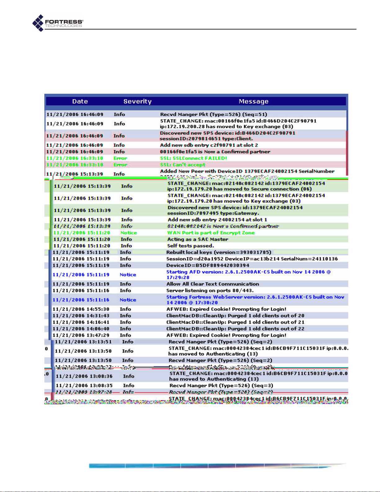
Fortress Bridge: Monitoring and Diagnostics
when Secure Clients contact and negotiate keys with the
Fortress Bridge
system configuration changes
when cryptographic processing is restarted
system and communication errors
The log is allocated 500 Kbytes of memory and can contain a
maximum of approximately 16,000 log messages (approximate
because record sizes vary somewhat). When the log is full, the
oldest records are overwritten as new messages are added to
the log.
74
Page 85

5.5 Diagnostics
Fortress Bridge: Monitoring and Diagnostics
Access Fortress Bridge diagnostic utilities by logging into the
Bridge GUI admin account and selecting
DIAGNOSTICS from the
menu on the left.
DIAGNOSTICS screen displays:
The
The version and build number of the firmware currently
running on the Fortress Bridge, under
The DEVICE ID of the Fortress Bridge, as uniquely generated
SOFTWARE VERSION.
for each device on a Fortress-secured network and used,
when applicable, for device authentication. (Refer to
Section 4.1 for more information about Device IDs.)
NOTE: Radio 1
uses antenna port
1
(ANT1); Radio 2 uses
antenna port 2 (ANT2).
5.5.1 Pinging a Device
1 Log on to the Bridge GUI admin or operator account and
choose
2 On the DIAGNOSTICS screen under UTILITIES, in Ping IP
DIAGNOSTICS from the menu on the left.
Address, enter the IP address of the device you want to
ping.
3 Click GO. The Bridge will ping the target IP five times and
display the
detail:
PING RESULTS.
5.5.2 Tracing a Packet Route
1 Log on to the Bridge GUI admin or operator account and
choose
2 On the DIAGNOSTICS screen under UTILITIES, in Traceroute
IP Address, enter the IP address of the device to which you
want to trace the route.
3 Click GO. The Bridge will trace the route to the target IP and
display the
DIAGNOSTICS from the menu on the left.
TRACEROUTE RESULTS.
75
Page 86

5.5.3 Flushing the Host MAC Database
The Fortress Bridge maintains a database of the MAC
addresses of devices in the unencrypted zone. You can flush
HOST MAC DATABASE:
the
1 Log on to the Bridge GUI admin account and choose
DIAGNOSTICS from the menu on the left.
2 At the bottom of the DIAGNOSTICS screen, click the FLUSH
HOST MAC DATABASE button.
3 Click OK on the confirmation system dialog. The Bridge
resets all connections to the unencrypted zone.
5.5.4 Generating a Diagnostics File
To assist in diagnosing a problem with your Bridge, the
Customer Support team at Fortress Technologies may request
that you generate a diagnostics file. Diagnostics files encrypt
the information collected from the Bridge, so the file can be
securely sent to Fortress Support as an e-mail attachment.
Fortress Bridge: Monitoring and Diagnostics
1 Log on to the Bridge admin account and access this page:
http://<IP_address>/support_package.html
where <IP_address> is the Bridge’s IP address.
2 On the system dialog, choose to save the file, support.pkg.
76
Page 87

5.6 Front-Panel Indicators
Fortress Bridge: Monitoring and Diagnostics
NOTE: There are
no LED indica-
tions in a Bridge in
blackout mode (refer to
77
Page 88

Stat2
can exhibit:
solid green - The Bridge is operating in root mode.
off - The Bridge is operating in non-root mode.
Clr
can exhibit:
fast green flash - The Bridge is passing cleartext
(unencrypted data) in the encrypted zone.
Fail
can exhibit:
off - The Fail LED does not apply to version 2.6.x of the
Fortress Bridge software. It is reserved for future support
for failover Bridge deployments.
Pwr
can exhibit:
solid green - The Bridge is powered on, either through the
+48V DC adapter inlet or the WAN port’s PoE connection.
off - Bridge is powered off.
5.6.2 Radio LEDs
The Bridge’s internal radios are each associated with a pair of
front-panel LEDs, labeled
Radio LEDs are arranged one above the other . Each radio then
has an associated upper and lower LED.
Fortress Bridge: Monitoring and Diagnostics
Radio1 and Radio2.
When the radio’s
Radio1 and Radio2 LEDs behave as shown below. (The LED
LED RSSI Monitor is Disabled (the default) the
RSSI Monitor and associated LED behaviors are described in
Section 3.3.2.7).
color/behavior upper LED lower LED both LEDs all four LEDs
AP or Root Bridge modes:
in
solid green
n/a
in
Non-Root Bridge mode:
active
n/a n/a
connected to root
intermittent green
solid amber
passing traffic n/a n/a n/a
n/a n/a n/a firmware error
off
n/a
Non-Root Bridge mode:
in
not connected to root
radio
disabled
both radios
disabled
The upper LED can exhibit:
intermittent green flash - The radio is passing traffic.
The lower LED can exhibit:
solid green - The meaning depends upon the radio’s mode
settings:
In AP or Root Bridge modes - The radio is active and
acting as an AP or a root Bridge.
In Non-Root Bridge mode - The radio is connected to the
root Bridge.
off - This state is meaningful only for a radio in Non-Root
Bridge
mode and indicates that the radio is not connected
to the root Bridge.
78
Page 89

Both upper and lower LEDs can exhibit:
off - The associated radio is disabled (in the Bridge GUI or
CLI).
All four Radio LEDs can exhibit:
solid amber - A firmware error has occurred.
off - Both radios are disabled (in the Bridge GUI or CLI).
5.6.3 Port LEDs
The Fortress Bridge’s Ethernet ports—including those for the
LAN switch, numbered
each equipped with two LEDs.
The Lnk/Act (link/activity) LEDs are located in the upper left
corner of each LAN switch port and to the left of the WAN
port. They indicate when a link has been est ablished for the
port (solid green) and show data activity on the link
(irregular flashing green).
The POE LED in the upper right corner of each LAN switch
port does not apply to version 2.6.x of the Fortress Bridge
firmware. It is reserved for future support for Bridge Power
over Ethernet (PoE) power sourcing equipment (PSE)
functionality.
The Pwr LED to the left of the WAN port illuminates
whenever the Bridge is powered up—whether the source of
power is PoE PSE or the +48V DC power inlet.
Fortress Bridge: Monitoring and Diagnostics
1 through 8, and for the WAN port—are
79
Page 90

Chapter 6 Command-Line Interface
6.1 Introduction
The Fortress Bridge CLI provides commands for managing the
Fortress Bridge and the network it secures. You can access it
through a direct connection to the Bridge’s serial console port
or, using Secure Shell (SSH), from any computer with access
to the Bridge—i.e., any computer in the Bridge’s unencrypted
zone or a computer running the Fortress Secure Client.
You do not need to be a root user to access the Bridge CLI.
Fortress Bridge: Command-Line Interface
NOTE: Fortress
Bridge features
and functions are de-
scribed in greater detail
in the preceding chap-
ters describing the use
of the Bridge GUI.
Up and down (
↑↓) arrow keys scroll through the command
history for a given CLI session, and the left and right (←→)
arrow keys navigate the current command line. The
Home key
moves the cursor to the beginning of the command line; the
End key moves the cursor to the end of the line. If your terminal
keyboard is not equipped with arrow keys, you can use these
keyboard equivalents:
arrow/numeric keypad keyboard equivalent
up arrow (↑)
down arrow (↓)
left arrow (←)
right arrow (→)
Home Ctrl-a
End Ctrl-e
Tab key auto-completes partial commands that are
The
Ctrl-u
Ctrl-d
Ctrl-l
Ctrl-r
sufficient to uniquely identify the command.
The
clear command clears the current terminal screen.
If the command output is longer than the display screen, the
CLI stops the list when the display is full and provides a
more
option that displays the next ten lines of output when you strike
Enter↵. To return to the command prompt without viewing all
available output, strike
Ctrl-c
.
Bridge CLI commands return
[Error]
, with a brief description of the error, when they do not.
[OK] when they execute and
80
Page 91

6.1.1 CLI Administrative Modes
There are two administrative modes in the Bridge CLI.
Fortress Bridge: Command-Line Interface
When you first access the CLI you are, by default, in Gateway
mode, indicated by the command prompt:
[GW]>
. In Gateway
mode, you can manage the Bridge’s Fortress controller device
functions, including basic administration and security settings.
The functions associated with the Bridge’s internal radios—its
AP/wireless bridge functions—are administered from Access
Point mode, indicated by the command prompt:
[AP]>
.
To access one mode from the other, simply enter the two-lett er
mode designation:
AP if you are in Gateway mode; GW if you are
in Access Point mode.
[GW]>
[AP]>
[GW]>
ap
gw
AP mode uses a submenu of commands to view and configure
virtual radio interfaces settings, otherwise known as virtual
access points (VAPs). Refer to Section 6.4.3.1 for more detail.
6.1.2 Accessing the CLI through the Serial Port
1 Using a standard Ethernet cable and the RJ-45-to-DB9
adapter that came with the Bridge, connect the Fortress
Bridge’s
2 Start your serial application and, if it is not already at these
settings, configure it to use:
bits per second: 9600
data bits: 8
parity: none
stop bits: 1
hardware flow control: none
Console port to a serial port on a computer.
NOTE: Bridge CLI
help
output shows
only those commands
and arguments that are
valid in the current ad-
ministrative mode (refer
to Section 6.2 for more
detail.)
NOTE: An RJ-45-
to-DB9 adapter—
included with each
Bridge—is required to
connect the serial
sole
port to a DB9 termi-
nal connection. Pin outs
for these adapters are
given in Table 7.1 on
page 116.
Con-
6.1.3 Accessing the CLI Remotely
When SSH is enabled, you can access the CLI through a
network connection to the Bridge’s
Unencrypted port by simply
pointing your terminal emulation application, configured with
the settings shown above, to the Bridge’s IP address.
Secure Shell (SSH) is disabled on the Fortress Bridge by
default. You must either enable SSH through the Bridge GUI
(Section 3.6.2) before you access the CLI remotely, or you
must make your initial connection to the Bridge CLI through a
direct connection to its
Console port (see above).
To enable SSH access to the Bridge CLI, follow the instructions
in Section 6.4.5.7 (for the CLI) or Section 3.6.2 (for the GUI).
6.1.4 Logging On and Off the CLI
To log on to the CLI, access the Fortress Bridge through a
terminal application and at the prompts enter the logon ID,
sysadm
and the password set for CLI access during installation.
81
Page 92

Fortress Bridge: Command-Line Interface
WSG login:
Password:
Fortress Wireless Security Gateway
[GW]>
sysadm
<password>
The login ID,
sysadm
, cannot be changed.
If you are changing the CLI password for the first time as part
of an installation procedure (Chapter 2) use the default
[GW]>
[GW]>
[GW]>
password,
To log off the CLI, use the
exit
quit
q
sysadm
.
exit
The CLI will time out and exit after five minutes of inactivity,
and you must log back in to regain access. This behavior is not
user configurable.
6.2 Getting Help in the CLI
Use the
to obtain the list of valid commands for the current
administrative mode.
You can obtain a usage example—and list the command’s
valid options with their valid arguments for the current
administrative mode—by entering a basic command without
options:
help
command (or its synonym, ?) without arguments
NOTE: The default
CLI password is
sysadm. Passwords
should never be left at
their defaults.
command or its synonyms:
[GW]>
Description: Displays system information, configuration
Usage: show [args]. Possible args:
8021X
auth
blackout
cleartext
clock
clients
compression
crypto
device
fips
gui
log
multicast
network
partners
radius
sac
snmp
sp
ssh
stp [bridgeName]
td
uptime
wanport
eapretryint
?|help
show
82
Page 93

Fortress Bridge: Command-Line Interface
Note that only those options available in the current
administrative mode are displayed and that valid command
options differ significantly between modes.
[AP]>
Description: Displays Access Point information, configuration
Usage: show [args]. Possible args:
associations
radio
radius
?|help
show
Several of the commands that change Bridge configuration
settings can be run interactively. When you enter a command
with one of its options, the parameters that can be configured
display as consecutively presented fields.
Obtain a usage example of command options for interactive
commands—and list the option’s valid switches and arguments
with a brief explanation of each—by entering
?
synonym,
[GW]>
Description: Sets network configuration
Usage: set network [-h hostname][-ip IP][-nm netmask][-gw defaultGW]
-gw 0: delete default gateway
set network ?
) after the command option:
help
(or its
For help with non-interactive command options, you can enter
the command-option combination without arguments:
[GW]>
set accessid
Description: Sets Access ID from a HEX string
Usage: set accessid <default|hexString>
default: set to all 0's
string of 16 HEX characters, ex: 0A0B0C0D0E0F2345
6.3 Command Syntax
In this document, command-line text supplied by the CLI is set
plain
in
bold
shown below:
[GW]> command option <parameter> {-switch req_arg1|req_arg2|req_arg3} [-switch opt_arg1|opt_arg2]
in which you can also note the terminology and punctuation
used here to describe command strings and parse input
elements:
Command refers to the basic operation to be performed
Option refers to the configuration element upon which the
Parameter refers to a user-supplied variable, (ex.,
Arguments (
(non-bold, non-italic) type. All user input is indicated by
typeface. The template for the CLI command syntax is
set, show
(ex.,
command will operate (ex.,
<
IPaddr
Some arguments are required by the command (
Others are optional (
>
, etc.).
, etc.).
clock, ap, clients
_arg
, above) are additional command inputs.
opt_arg
). Multiple arguments must be
, etc.)
<
name
req_arg
separated by commas and entered without spaces.
>
).
NOTE: Bridge CLI
commands, op-
tions, arguments and
switches are case-sensi-
tive, and all user-sup-
,
plied inputs must be
entered without spaces.
83
Page 94

Switch refers to the identifier, preceded by a dash
(hyphen), for the argument to follow (ex.,
Switches allow permissible arguments to be entered in any
combination and order.
Angle brackets: indicate variable, user-supplied inputs
(parameters and variable arguments), which are also
italicized (ex.,
The absence of angle brackets and italics indicates literal
(or fixed) user-supplied input (ex.,
Braces indicate that the arguments enclosed are required
by the command (ex.,
Square brackets indicate optional arguments (ex.,
[all|
<port1,port2,...>
Pipes are placed between mutually exclusive arguments
[
<accessID>
(ex.,
An ellipse indicates than the argument can include more
entries of the same kind (ex.,
<sharedkey>, <port1,port2,...>
[P|B|N]
{y|n}
).
]
.
|default]
.
<port1,port2,...>
6.4 Configuration in the Bridge CLI
Fortress Bridge: Command-Line Interface
-ip, -n
, etc.)
).
).
).
6.4.1 LAN Settings in the CLI
View network properties with the
[GW]>
Hostname:FTIPegasus
DefaultGateway:192.168.254.1
IP(Private):192.168.254.254
Netmask(Private):255.255.255.0
show network
Configurable parameters assign the Bridge’s host name and its
management interface IP and subnet addresses and identify
the default gateway (or router) for the network on which you
are installing the Bridge.
The
show network command is valid only in GW (gateway)
mode (refer to Section 6.1.1 for more detail).
Configure network properties for the Fortress Bridge with the
set network
[GW]> set network
Hostname:
[OK] setting hostname
IPaddress:
[OK] IP accepted, will test with netmask before setting
Netmask:
[OK] setting netmask
DefaultGateway:
[OK] setting default gateway
[OK] setting IP
Update Certificate done
Reboot is required. [Y|N]?
<BridgeName>
<BridgeName>
<BridgeSubnet>
<BridgeIPaddr>
command, as follows:
show network
command:
NOTE: The For-
tress Bridge’s de-
fault IP address is:
192.168.254.254
NOTE: The IP ad-
dress you assign
should be unique on the
network.
84
Page 95

Fortress Bridge: Command-Line Interface
The CLI displays the configurable fields for set network one at
a time. Enter a new value for the field—or leave the field blank
and the setting unchanged—and strike
Enter↵, to display the
next field. The final reboot query displays only when you have
entered a value into at least one of the fields presented.
Entering the
0 (zero) argument for the DefaultGateway option
deletes the default gateway from the Bridge’s network
configuration.
Alternatively, you can run
set network
non-interactively with
valid switches and arguments in any order and combination:
[GW]>
set network [-h <BridgeName>
] [-ip <BridgeIP>
] [-nm <BridgeSubnet>
Regardless of the method you use to reconfigure these
settings, you must reboot the Bridge in order for the change to
any network setting other than host name to take effect. To do
so, simply strike
The
set network command is valid only in GW (gateway)
Enter↵ at the prompt (Y is the default).
mode (refer to Section 6.1.1 for more detail).
6.4.2 Spanning Tree Protocol in the CLI
STP link managementis enabled on the Fortress Bridge by
default.
You can view whether STP is currently enabled (
off) with show stp:
[GW]
On
>
show stp
disabled (
on) or
] [-gw <DFLTgatewayIP>
|0]
85
Page 96

Fortress Bridge: Command-Line Interface
[AP]>
[RADIO 1]
Radio State: On
Radio Band: 802.11g
Radio Mode: AP
Channel: 1
Tx Power: Auto
Distance: 1
Beacon Interval: 100
Preamble: Short
Multicast: On
RSSI Monitor: Off
[RADIO 2]
State: On
Radio Band: 802.11a
Radio Mode: Bridge
Bridge Mode: Root
Channel: 149
Tx Power: Auto
Distance: 1
Beacon Interval: 100
Multicast: On
RSSI Monitor: Off
show radio
RADIO 1
identifies the 802.11a/b/g, multi-mode radio
associated with the Bridges’ antenna port 1 (
RADIO 2 identifies the higher-gain 802.11a radio associated
with antenna port 2 (
To view the current setting for a radio individually, specify the
radio by number (
[AP]>
[RADIO 1]
Radio State: On
Radio Band: 802.11g
Radio Mode: AP
Channel: 1
Tx Power: Auto
Distance: 1
Beacon Interval: 100
Preamble: Short
Multicast: On
RSSI Monitor: Off
show radio 1
ANT2).
1 or 2):
ANT1), while
NOTE: The Bridge
CLI makes avail-
able certain Linux®
Wireless Extension
Tools for the configura-
tion of the Atheros®
wireless driver. These
can be used for addi-
tional WLAN configura-
tion. Refer to Section 6.7
for more detail.
Configure radio settings interactively by entering the set
command with just the
radio 1 or radio 2 argument. The
Bridge CLI presents one field at a time, and you can either
enter a new value for a given field or strike
Enter↵ to leave the
value unchanged and go on to the next field.
The options presented depend, in part, on the configuration
choices you make. A radio with a
instance, will not provide you an opportunity to set the
Mode
, unless you change the Radio Mode to
point the
Bridge Mode option will be inserted dynamically, as
Radio Mode setting of ap, for
Bridge
bridge
, at which
shown below.
NOTE: If you are
deploying multi-
ple Fortress Bridges in a
point-to-point/multi-
point network they
must be correctly con-
figured for their net-
work roles, typically
with one serving as the
root node and the rest
configured as non-root
nodes (refer to Section
3.3.1.4 for more detail).
86
Page 97

Fortress Bridge: Command-Line Interface
[AP]>
Radio state [on|off] (on):
Radio band [802.11g|802.11a] (802.11g):
[OK]
Reboot is required when changing radio band
Radio Mode [ap|bridge|ids] (ap):
[OK]
Bridge Mode [root|nonroot] (nonroot):
Radio is in nonroot mode...cannot set channel
Transmit Power [auto|1-18] (auto):
Distance in miles [1-35] (1):
[OK]
Beacon interval (ms) [25..1000] (100):
Multicast [on|off] (on):off
RSSI Monitor [on|off] (off):
[OK]
Committing changes...
Reboot is required. [Y|N]?
set radio 1
802.11a
bridge
nonroot
3
on
y
As indicated in the output above, the Channel setting does not
apply to the bridging radios of non-root Bridges, which do not
bind to a channel, but rather to an SSID. In contrast,
Multicast applies exclusively the bridging radios of non-root
Bridges, and it is only when configuring such radios that you
will see the
Multicast option.
In root bridge and AP radios, the channels available for
selection depend on the 802.11 band used by the radio:
channels 36, 40, 44, 48, 52, 56, 60, 64, 149, 153, 157, or 161
are available for 802.11a radios; channels 1–11, inclusive are
available for Radio 1 when it is configured to use the 802.11g
band.
Configuration settings for Radio 2 omit the
Radio band option;
Radio 2 is fixed on the 802.11a band. Configurable options—
with their selection-dependent permutations—are otherwise
the same for both radios.
[AP]>
Radio state [on|off] (on):
Radio 2 band fixed at 802.11a
Radio Mode [ap|bridge] (bridge):
[OK]
Channel [36|40|44|48|52|56|60|64|149|153|157|161] (149):
[OK]
Transmit Power [auto|1-18] (auto):
[OK]
Beacon interval (ms) [25..1000] (100):
RSSI Monitor [on|off] (off):
Committing changes...
Reboot is required. [Y|N]?
set radio 2
ap
18
44
NOTE: Because
STP requires mul-
ticasting, the multicast
option will be absent
(and the feature en-
abled) for non-root
bridging radios. If you
disable STP (Section
6.4.2) the multicast
option will be presented
for a non-root bridging
radio.
Alternatively, you can use the set radio command with valid
switches and arguments to change the settings of either radio:
[AP]>
[-bmode root|nonroot] [-channel <channel#>] [-txpower auto|1–18] [-distance 1–35]
[-beaconint 20–1000] [-preamble short|long] [-multicast on|off] [-rssimon on|off]
set radio {1|2} [-state on|off] [-band 802.11g|802.11a] [-rmode ap|bridge]
87
Page 98

Fortress Bridge: Command-Line Interface
The sample output for the show radio command (at the
beginning of this section) shows the default radio settings.
As shown in the example interactive
set radio output,
reconfiguring radio settings requires that you reboot the Bridge
in order to effect your changes.
The
show radio and set radio commands are valid only in AP
(access point) mode (refer to Section 6.1.1 for more detail).
6.4.3.1 Virtual Radio Interface Settings in the CLI
The Bridge CLI AP mode uses a submenu of commands to
view and configure virtual radio interfaces settings, otherwise
known as virtual access points (VAPs).
Use the
vapcfg command to access these commands. You
must specify the radio associated with the virtual interface(s)
you want to configure with the
vapcfg command (the CLI will
prompt you for a radio number if you do not enter it with the
command).
[AP]>
[VAP]>
vapcfg radio 1
The command prompt (VAP) reflects the fact that you are in
VAP-configuration mode.
The
vapcfg command is valid only in AP mode. So in order to
access the VAP command set for the other radio, you must
return to AP mode and re-enter the
illustrated in the output of the
show command to view the current virtual radio interface
vapcfg command. This is
show command below. Use the
configuration:
[AP]>
[VAP]>
[RADIO 1]
[VAP 1]
SSID: Base-11g
DTIM: 1
Hide SSID: off
RTS Threshold: off
Frag Threshold: off
Only 11g: off
Security Suite: fortress
[VAP]>
[AP]>
[VAP]>
[RADIO 2]
[VAP 1]
SSID: Base-11a
DTIM: 1
Hide SSID: off
RTS Threshold: off
Frag Threshold: off
Security Suite: fortress
vapcfg radio 1
show vap
ap
vapcfg radio 2
show vap
88
Page 99

Fortress Bridge: Command-Line Interface
By default a single virtual access point (vap 1) is configured for
each radio. The SSIDs associated with these two primary
VAPs should never be left at their defaults (shown above).
SSID strings can be up to 32 characters long.
Configure VAP settings interactively by entering the
command with just the
vap <N> argument, where N is the VAP
number. The Bridge CLI presents one field at a time, and you
can either enter a new value for a given field or strike
leave the value unchanged and go on to the next field.
You can reconfigure existing VAPs with the
[VAP]>
SSID [String <= 32] (Base-11g):
[OK]
DTIM [1-255] (1):
Hide SSID [on|off] (off):
RTS Threshold [off|1-2345] (off):
Frag Threshold [off|256-2345] (off):
Only 11g [on|off] (off):
Security Suite [? for options] (fortress):
Committing changes...
Reboot is required. [Y|N]?
set vap 1
0123xyz
You can also use the set command interactively to configure
the same parameters for new VAPs.
Entering a dot (
The
Security Suite field will accept any of eleven possible
.
) at the SSID prompt clears the SSID string.
entries, and the differing parameters required for each are
presented interactively once you have entered your selection.
The CLI provides a list of possible
when a question mark (
Suite
options and the parameters required to configure them
?
) is entered for the field. (Security
are described in detail in Section 3.3.4).
set
Enter↵ to
set command:
Security Suite options
[AP]>
[VAP]>
SSID [String <= 32] ():
[OK]
DTIM [1-255] (1):
Hide SSID [on|off] (off):
[OK]
RTS Threshold [off|1-2345] (off):
Frag Threshold [off|256-2345] (off):
Only 11g [on|off] (off):
Security Suite [? for options] (fortress):
Possible Security Suites: [fortress|clear|open-wep|sharedwep|8021x|wpa|wpa-psk|
wpa2|wpa2-psk|wpa-mixed|wpa-mixed-psk]
Security Suite [? for options] (fortress):
[OK]
Rekey period [seconds] (600):
[OK]
Committing changes...
Reboot is required. [Y|N]??
vapcfg radio 1
set vap 2
0987abc
on
?
wpa
300
Alternatively, you can use the set vap command with valid
switches and arguments to change the settings of any VAP:
89
Page 100

Fortress Bridge: Command-Line Interface
[VAP]>
[-rts 1–2345|off] [-frag 256–2345|off] [-only11g on|off]
[-suite fortress|clear|open-wep|shared-wep|8021x|wpa|wpa-psk|wpa2|wpa2-psk|wpa-mixed|wpa-mixed-psk]
[-wepkeytype hex|passphrase] [-wepkeysize 40|104] [-wepkey1
[-wepkey3
[-passphrase
set vap {1|2|3|4} [-ssid
<key>
] [-wepkey4
<phrase>
] [-hex
<key>
<key>
<ssidstring>
] [-weptxkey 1–4] [-keytype hex|passphrase] [-rekeyperiod
]
|.] [-dtim 1-255] [-hidessid on|off]
<key>
] [-wepkey2
<key>
]
<sec>
]
In the dot (.) input for the -ssid switch clears the SSID string.
The output of
set vap help provides guidance for many of the
Security Suite parameters shown above (described in detail in
Section 3.3.4).
Security Suite options
fortress and clear require no further
parameters to be set. When you have configured a different
Security Suite setting, you can view the parameters configured
for it with the
[VAP]>
[RADIO 1]
[VAP 2]
SSID: 0987abc
DTIM: 1
Hide SSID: on
RTS Threshold: off
Frag Threshold: off
Only 11g: off
Security Suite: wpa
Rekey period: 300
show vap 2
show command.
You can clear the settings for VAPs 2 through 4, effectively
deleting them from the radio configuration.
[VAP]>
Committing changes...
Reboot is required. [Y|N]?
clear vap 2
Radio 1 and Radio 2 each require a VAP 1 to be configured at
all times. So, while you can edit VAP 1 on either radio, with the
set command, you cannot clear it. Attempting to do so will
result in an error message that offers you the alternative of
resetting VAP 1 to its default configuration.
The
VAP submenu can be accessed only from AP mode (refer
to Section 6.1.1 for more detail), and you can return to AP
mode with the
In VAP mode the standard
AP command.
quit and reboot commands
remain available. Changes to Bridge radio virtual interfaces
always require you to reboot, as shown in the example output
throughout this section.
6.4.4 Bridge Passwords in the CLI
Two passwords apply to the Bridge GUI, one for the admin
(administrator) account, and one for the operator (view-only)
account. The Bridge CLI has only an administrator account.
90
 Loading...