

Page 1

Fortress Security System
Secure Wireless Bridge
and Security Controller
Software GUI Guide
www.fortresstech.com
© 2010 Fortress Technologies
Page 2

Bridge GUI Guide
Fortress Bridge and Controller version 5.4 Software GUI Guide [rev.1]
Copyright © 2010 Fortress Technologies, Inc. All rights reserved.
This document contains proprietary information protected by co pyr ig h t. N o part of this
document may be reproduced or transmitted in any form or by any means, electronic or
mechanical, without written permission of Fortress Technologies, 4023 Tampa Road, Suite
2200, Oldsmar, FL 34677, except as specified in the Product Warranty and License Terms.
FORTRESS TECHNOLOGIES, INC., MAKES NO WARRANTY OF ANY KIND WITH
REGARD TO THIS MATERIAL, INCLUDING BUT NOT LIMITED TO THE IMPLIED
WARRANTIES OF MERCHANT ABILITY AND FITNESS FOR A P AR TICULAR PURPOSE.
FORTRESS TECHNOLOGIES, INC. SHALL NOT BE LIABLE FOR ERRORS
CONTAINED HEREIN OR FOR INCIDENTAL OR CONSEQUENTIAL DAMAGES IN
CONNECTION WITH THE FURNISHING, PERFORMANCE OR USE OF THIS
MATERIAL. THE INFORMATION IN THIS DOCUMENT IS SUBJECT TO CHANGE
WITHOUT NOTICE.
The Fortress Technologies and AirFortress logos and AirFortress and are registered
trademarks; Multi-Factor Authentication, Unified Security Model, Wireless Link Layer
Security and Three Factor Authentication (TFA) are trademarks of Fortress Technologies,
Inc. The technology behind Wireless Link Layer Security™ enjoys U.S. and international
patent protection under patent number 5,757,924.
Portions of this software are covered by the GNU General Public License (GPL) Copyright
© 1989, 1991 Free Software Foundation, Inc,. 59 Temple Place, Suite 330, Boston, MA
02111-1307 USA.
To receive a complete machine-readable copy of the corresponding source code on CD,
send $10 (to cover the costs of production and mailing) to: Fortress Technologies; 4023
Tampa Road, suite 2200; Oldsmar, FL 34677-3216. Please be sure to include a copy of
your Fortress Technologies invoice and a valid “ship to” address.
This product includes cryptographic software written by Eric Young (eay@cryptsoft.com).
This product includes software written by Tim Hudson (tjh@cryptsoft.com).
Copyright © 1995-1998 Eric Young (eay@cryptsof t.com) All rights reserved.
This package is an SSL implementation written by Eric Young (eay@cryptsoft.com). The
implementation was written so as to conform with Netscape’s SSL.
THIS SOFTWARE IS PROVIDED BY ERIC YOUNG ``AS IS'' AND ANY EXPRESS OR
IMPLIED WARRANTIES, INCLUDING, BUT NOT LIMITED TO, THE IMPLIED
WARRANTIES OF MERCHANTABILITY AND FITNESS FOR A PARTICULAR PURPOSE
ARE DISCLAIMED. IN NO EVENT SHALL THE AUTHOR OR CONTRIBUTORS BE
LIABLE FOR ANY DIRECT, INDIRECT, INCIDENTAL, SPECIAL, EXEMPLARY, OR
CONSEQUENTIAL DAMAGES (INCLUDING, BUT NOT LIMITED TO, PROCUREMENT
OF SUBSTITUTE GOODS OR SERVICES; LOSS OF USE, DATA, OR PROFITS; OR
BUSINESS INTERRUPTION) HOWEVER CAUSED AND ON ANY THEORY OF
LIABILITY, WHETHER IN CONTRACT, STRICT LIABILITY, OR TORT (INCLUDING
NEGLIGENCE OR OTHERWISE) ARISING IN ANY WAY OUT OF THE USE OF THIS
SOFTWARE, EVEN IF ADVISED OF THE POSSIBILITY OF SUCH DAMAGE.
Atheros, the Atheros logo, Atheros Driven, Driving the wireless future, Super G and Super
AG are all registered trademarks of Atheros Communications. ROCm, JumpStart for
Wireless, Atheros XR, Wake-on-Wireless, Wake-on-Theft, and FastFrames, are all
trademarks of Atheros Communications, Inc.
This product uses Dynamic Host Control Protocol, Copyright © 2004–2010 by Internet
Software Consortium, Inc. Copyright © 1995–2003 by Internet Software Consortium. All
rights reserved.
This product includes software developed by the OpenSSL Project for use in the OpenSSL
Toolkit. (http://www.openssl.org/)
Copyright © 1998-2007 The OpenSSL Project. All rights reserved.THIS SOF TWARE IS
PROVIDED BY THE OpenSSL PROJECT ``AS IS'' AND ANY EXPRESSED OR IMPLIED
WARRANTIES, INCLUDING, BUT NOT LIMITED TO, THE IMPLIED WARRANTIES OF
MERCHANTABILITY AND FITNESS FOR A PARTICULAR PURPOSE ARE
DISCLAIMED. IN NO EVENT SHALL THE OpenSSL PROJECT OR ITS CONTRIBUTORS
009-00035-00v5.4r1
i
Page 3

BE LIABLE FOR ANY DIRECT, INDIRECT, INCIDENT AL, SPECIAL, EXEMPLARY, OR
CONSEQUENTIAL DAMAGES (INCLUDING, BUT NOT LIMITED TO, PROCUREMENT
OF SUBSTITUTE GOODS OR SERVICES; LOSS OF USE, DATA, OR PROFITS; OR
BUSINESS INTERRUPTION) HOWEVER CAUSED AND ON ANY THEORY OF
LIABILITY, WHETHER IN CONTRACT, STRICT LIABILITY, OR TORT (INCLUDING
NEGLIGENCE OR OTHERWISE) ARISING IN ANY WAY OUT OF THE USE OF THIS
SOFTWARE, EVEN IF ADVISED OF THE POSSIBILITY OF SUCH DAMAGE.
This product uses Net-SNMP Copyright © 1989, 1991, 1992 by Carnegie Mellon
University, Derivative Work - 1996, 1998-2000. Copyright © 1996, 1998-2000 The Regents
of the University of California. All rights reserved. Copyright © 2001-2003, Cambridge
Broadband Ltd. All rights reserved. Copyright © 2003 Sun Microsystems, Inc. All rights
reserved. Copyright © 2001-2006, Networks Associates Technology, Inc. All rights
reserved. Center of Beijing University of Posts and Telecommunications. All rights
reserved.
Licensed under the Apache License, Version 2.0 (the "License"); you may not use this file
except in compliance with the License. You may obtain a copy of the License at http://
www.apache.org/licenses/LICENSE-2.0. Unless required by applicable law or agreed to in
writing, software distributed under the License is distributed on an "AS IS" BASIS,
WITHOUT WARRANTIES OR CONDITIONS OF ANY KIND, either express or implied.
See the License for the specific language governing permissions and limitations under the
License.
Microsoft and Windows are registered trademarks of the Microsoft Corporation.
Firefox is a trademark of the Mozilla Foundation.
SSH is a trademark of SSH Communication Security.
All other trademarks mentioned in this document are the property of their respective
owners.
Bridge GUI Guide
End User License Agreement (EULA)
IMPORTANT; PLEASE READ THIS END USER LICENSE AGREEMENT CAREFULLY.
DOWNLOADING, INSTALLING OR USING FORTRESS TECHNOLOGIES SOFTWARE
CONSTITUTES ACCEPT ANCE OF THIS AGREEMENT.
FORTRESS TECHNOLOGIES, INC., WILL LICENSE ITS SOFTWARE TO YOU THE
CUSTOMER (END USER) ONLY UPON THE CONDITION THAT YOU ACCEPT ALL OF
THE TERMS CONTAINED IN THIS END USER LICENSE AGREEMENT. THE ACT OF
DOWNLOADING, INSTALLING, OR USING FORTRESS SOFTWARE, BINDS YOU AND
THE BUSINESS THAT YOU REPRESENT (COLLECTIVELY, “CUSTOMER”) TO THE
AGREEMENT.
License
Fortress grants to Customer (“Licensee”) a non-exclusive and non-transferable right to use
the Fortress Software Product (“Software”) described in the Fortress Product Description
for which Customer has paid any required license fees and subject to the use rights and
limitations in this Agreement. Unless otherwise agreed to in writing, use of th e Software is
limited to the number of authorized users for which Licensee has purchased the right to the
use of the software. Software is authorized for installation on any Fortress approved
device. “Software” includes computer program(s) and any documentation (whether
contained in user manuals, technical manuals, training materials, specifications, etc.) that
is included with the software (including CD-ROM, or on-line). Software is authorized for
installation on a single use computing device such as Fortress hardware platform,
computer, laptop, PDA or any other computing device. Software is not licensed for
installation or embedded use on any other system(s) controlling access to a secondary
network of devices or securing access for any separate computing devices. Software
contains proprietary technology of Fortress or third parties. No ownership in or title to the
Software is transferred. Software is protected by copyright laws and inte rn a ti o na l trea ti e s .
Customer may be required to input a software license key to initialize the software
installation process.
ii
Page 4

Customer may make backup or archival copies of Software and use Software on a backup
processor temporarily in the event of a processor malfunction. Any full or partial copy of
Software must include all copyright and other proprietary notices which appear on or in the
Software. Control functions may be installed and enabled. Customer may not modify
control utilities. Customer may not disclose or make available Software to any other party
or permit others to use it except Customer's employees and agents who use it on
Customer's behalf and who have agreed to these license terms. Customer may not transfer
the software to another party except with Fortress' written permission. Customer agrees
not to reverse engineer, decompile, or disassemble the Software. Customer shall maintain
adequate records matching the use of Software to license grants and shall make the
records available to Fortress or the third party developer or owner of the Software on
reasonable notice. Fortress may terminate any license granted hereunder if Customer
breaches any license term. Upon termination of the Agreement, Customer shall destroy or
return to Fortress all copies of Software.
General Limitations
This is a License for the use of Fortress Software Product and documentation; it is not a
transfer of title. Fortress retains ownership of all copies of the Software and
Documentation. Customer acknowledges that Fortress or Fortress Solution Provider trade
secrets are contained within the Software and Documentation. Except as otherwise
expressly provided under the Agreement, Customer shall have no right and Customer
specifically agrees not to:
i.Transfer, assign or sublicense its license rights to any other person or entity and
Customer acknowledges that any attempt to transfer, assign or sublicense shall “void” the
license;
ii.Make modifications to or adapt the Software or create a derivative work based on the
Software, or permit third parties to do the same;
iii.Reverse engineer, decompile, or disassemble the Software to a human-readable form,
except to the extent otherwise expressly permitted under applicable law notwithstanding
this restriction and;
iv.Disclose, provide, or otherwise make available trade secrets contained within the
Software and Documentation in any form to any third party without the prior written consent
of Fortress Technologies. Customer shall implement reasonable security measures to
protect such trade secrets.
Software, Upgrades and Additional Copies
For purposes of the Agreement, “Software” shall include computer programs, includ ing
firmware, as provided to Customer by Fortress or a Fortress Solution Provider, and any (a)
bug fixes, (b) maintenance releases, (c) minor and major upgrades as deemed to be
included under this agreement by Fortress or backup co pies of any of the foregoing.
NOTWITHSTANDING ANY OTHER PROVISION OF THE AGREEMENT:
i.CUSTOMER HAS NO LICENSE OR RIGHT TO MAKE OR USE ANY ADDITIONAL
COPIES OR UPGRADES UNLESS CUSTOMER, AT THE TIME OF MAKING OR
ACQUIRING SUCH COPY OR UPGRADE, ALREADY HOLDS A VALID LICENSE TO
THE ORIGINAL SOFTWARE AND HAS PAID THE APPLICABLE FEE FOR THE
UPGRADE OR ADDITIONAL COPIES;
ii.USE OF UPGRADES IS LIMITED TO FORTRESS EQUIPMENT FOR WHICH
CUSTOMER IS THE ORIGINAL END USER CUSTOMER OR LESSEE OR OTHERWISE
HOLDS A VALID LICENSE TO USE THE SOFTW ARE WHICH IS BEING UPGRADED;
AND;
iii.THE MAKING AND USE OF ADDITIONAL COPIES IS LIMITED TO NECESSARY
BACKUP PURPOSES ONLY.
Proprietary Notices
All copyright and other proprietary notices on all copies of the Software shall be maintained
and reproduced by the Customer in the same manner that such copyright and other
proprietary notices are included on the Software. Customer shall not make any copies or
duplicates of any Software without the prior written permission of Fortress; except as
expressly authorized in the Agreement.
Bridge GUI Guide
iii
Page 5

Term and Termination
This Agreement and License shall remain in effect until terminated through one of the
following circumstances:
i.Agreement and License may be terminated by the Customer at any time by destroying all
copies of the Software and any Documentation.
ii.Agreement and License may be terminated by Fortress due to Customer non-compliance
with any provision of the Agreement.
Upon termination by either the Customer or Fortress, the Customer shall destroy or return
to Fortress all copies of Software and Documentation in its possession or control. All
limitations of liability, disclaimers, restrictions of warranty, and all confidentiality obligations
of Customer shall survive termination of this Agreement. Also, the provisions set-forth in
the sections titled “U.S. Government Customers” and “General Terms Applicable to the
Limited Warranty S tatement and End User License Agreement” shall survive termination of
the Agreement.
Customer Records
Fortress and its independent accountants reserve the right to conduct an audit of Customer
records to verify compliance with this agreement. Customer grants to Fortress and its
independent accountants access to its books, records and accounts during Customer's
normal business hours in support of such an audit. Customer shall pay to Fortress the
appropriate license fees, plus the reasonable cost of conducting the audit should an audit
disclose non-compliance with this Agreement.
Export Restrictions
Customer acknowledges that the laws and regulations of the United States restrict the
export and re-export of certain commodities and technical data of United States origin,
including the Product, Software and the Documentation, in any medium. Customer will not
knowingly, without prior authorization if required, export or re-export the Product, Software
or the Documentation in any medium without the appropriate United States and foreign
government licenses. The transfer or export of the software outside the U.S. may require a
license from the Bureau of Industry and Security . For questions call BIS at 202-482-4811.
U.S Government Customers
The Software and associated documentation were developed at private expense and are
delivered and licensed as “commercial computer software” as defined in DFARS 252.2277013, DFARS 252.227-7014, or DFARS 252.2 27-7015 as a “commercial item” as defined
in FAR 2.101(a), or as “Restricted computer software” as defined in FAR 52.227-19. All
other technical data, including manuals or instructional materials, are provided with
“Limited Rights” as defined in DFAR 252.227-7013 (a) (15), or FAR 52.227-14 (a) and in
Alternative II (JUN 1987) of that clause, as applicable.
Limited Warranty
The warranties provided by Fortress in this Statement of Limited Warranty apply only to
Fortress Products purchased from Fortress or from a Fortress Solution Provider for internal
use on Customer's computer network. “Product” means a Fortress software product,
upgrades, or firmware, or any combination thereof. The term “Product” also includes
Fortress software programs, whether pre-loaded with the Fortress hardware Product,
installed subsequently or otherwise. Unless Fortress specifies otherwise, the following
warranties apply only in the country where Customer acquires the Product. Nothing in th is
Statement of Warranty affects any statutory rights of consumers that cannot be waived or
limited by contract.
Customer is responsible for determining the suitability of the Products in Customer's
network environment. Unless otherwise agreed, Customer is responsible for the Product's
installation, set-up, configuration, and for password and digital signature management.
Fortress warrants the Products will conform to the published specifications and will be free
of defects in materials and workmanship. Customer must notify Fortress within the
specified warranty period of any claim of such defect. The warranty period for software is
one (1) year commencing from the ship date to Customer [and in the case of resale by a
Fortress Solution Provider, commencing not more than (90) days after original shipment by
Bridge GUI Guide
iv
Page 6

Fortress]. Date of shipment is established per the shipping document (packing list) for the
Product that is shipped from Fortress location.
Customer shall provide Fortress with access to the Product to enable Fortress to diagnose
and correct any errors or defects. If the Product is found defective by Fortress, Fortress'
sole obligation under this warranty is to remedy such defect at Fortress' option through
repair, upgrade or replacement of product. Services and support provided to diagnose a
reported issue with a Fortress Product, which is then determined not to be the root cause of
the issue, may at Fortress’ option be billed at the standard time and material rates.
Warranty Exclusions
The warranty does not cover Fortress Hardware Product or Software or any other
equipment upon which the Software is authorized by Fortress or its suppliers or licensors,
which (a) has been damaged through abuse or negligence or by accident, (b) has been
altered except by an authorized Fortress representative, (c) has been subjected to
abnormal physical or electrical stress (i.e., lightning strike) or abnormal environmental
conditions, (d) has been lost or damaged in transit, or (e) has not been installed, operated,
repaired or maintained in accordance with instructions provided by Fortress.
The warranty is voided by removing any tamper evidence security sticker or marking
except as performed by a Fortress authorized service technician.
Fortress does not warrant uninterrupted or error-free operation of any Products or third
party software, including public domain software which may have been incorporated into
the Fortress Product.
Fortress will bear no responsibility with respect to any defect or deficiency resulting from
accidents, misuse, neglect, modifications, or deficiencies in power or operating
environment.
Unless specified otherwise, Fortress does not warrant or support non-Fortress products. If
any service or support is rendered such support is provided WITHOUT WARRANTIES OF
ANY KIND.
DISCLAIMER OF WARRANTY
THE WARRANTIES HEREIN ARE SOLE AND EXCLUSIVE, AND NO OTHER
WARRANTY, WHETHER WRITTEN OR ORAL, IS EXPRESSED OR IMPLIED. TO THE
EXTENT PERMITTED BY LAW, FORTRESS SPECIFICALLY DISCLAIMS THE IMPLIED
WARRANTIES OF MERCHANTABILITY, FITNESS FOR A PARTICULAR PURPOSE,
TITLE AND NONINFRINGEMENT.
General Terms Applicable to the Limited Warranty and End User License Agreement
Disclaimer of Liabilities
THE FOREGOING WARRANTIES ARE THE EXCLUSIVE WARRANTIES AND REPLACE
ALL OTHER WARRANTIES OR CONDITIONS, EXPRESS OR IMPLIED, INCLUDING,
BUT NOT LIMITED TO, THE IMPLIED WARRANTIES OR CONDITIONS OF
MERCHANTABILITY AND FITNESS FOR A PARTICULAR PURPOSE. FORTRESS
SHALL HAVE NO LIABILITY FOR CONSEQUENTIAL, EXEMPLARY, OR INCIDENTAL
DAMAGES EVEN IF IT HAS BEEN ADVISED OF THE POSSIBILITY OF SUCH
DAMAGES. THE STATED LIMITED WARRANTY IS IN LIEU OF ALL LIABILITIES OR
OBLIGATIONS OF FOR TRESS FOR DAMAGES ARISING OUT OF OR IN CONNECTION
WITH THE DELIVERY, USE, OR PERFORMANCE OF THE PRODUCTS (HARDWARE
AND SOFTWARE). THESE WARRANTIES GIVE SPECIFIC LEGAL RIGHTS AND
CUSTOMER MAY ALSO HAVE OTHER RIGHTS WHICH VARY FROM JURISDICTION
TO JURISDICTION. SOME JURISDICTIONS DO NOT ALLOW THE EXCLUSION OR
LIMITATION OF EXPRESS OR IMPLIED WARRANTIES, SO THE ABOVE EXCLUSION
OR LIMIT ATION MAY NOT APPLY TO YOU. IN THAT EVENT, SUCH WARRANTIES ARE
LIMITED IN DURATION TO THE WARRANTY PERIOD. NO WARRANTIES APPLY
AFTER THAT PERIOD.
Product Warranty and License Terms
Indemnification
Fortress will defend any action brought against Customer based on a claim that any
Fortress Product infringes any U.S. patents or copyrights excluding third party software,
provided that Fortress is immediately notified in writing and Fortress has the right to control
Bridge GUI Guide
v
Page 7

the defense of all such claims, lawsuits, and other proceedings. If, as a result of any claim
of infringement against any U.S. patent or copyright, Fortress is enjoined from using the
Product, or if Fortress believes the Product is likely to become the subject of a claim of
infringement, Fortress at its option and expense may procure the right for Customer to
continue to use the Product, or replace or modify the Product so as to make it noninfringing. If neither of these two options is reasonably practicable, Fortress may
discontinue the license granted herein on one month's written notice and refund to
Licensee the unamortized portion of the license fees hereunder. The depreciation shall be
an equal amount per year over the life of the Product as established by Fortress. The
foregoing states the entire liability of Fortress and the sole and exclusive remedy of the
Customer with respect to infringement of third party intellectual property.
Limitation of Liability
Circumstances may arise where, because of a default on Fortress' part or other liability,
Customer is entitled to recover damages from Fortress. In each such instance, regardless
of the basis on which you are entitled to claim damages from Fortress (including
fundamental breach, negligence, misrepresentation, or other contract or tort claim),
Fortress is liable for no more than damages for bodily injury (including death) and damage
to real property and tangible personal property, and the amount of any other actual direct
damages, up to either U.S. $25,000 (or equivalent in local currency) or the charges (if
recurring, 12 months' charges apply) for the Product that is the subject of the claim,
whichever is less. This limit also applies to Fortress' Solution Providers. It is the maximum
for which Fortress and its Solution Providers are collectively responsible.
UNDER NO CIRCUMSTANCES IS FORTRESS LIABLE FOR ANY OF THE FOLLOWING:
1) THIRD-PARTY CLAIMS AGAINST YOU FOR DAMAGES,
2) LOSS OF, OR DAMAGE TO, YOUR RECORDS OR DATA, OR
3) SPECIAL, INCIDENTAL, OR INDIRECT DAMAGES OR FOR ANY ECONOMIC
CONSEQUENTIAL DAMAGES (INCLUDING LOST PROFITS OR SAVINGS), EVEN IF
FORTRESS OR ITS SOLUTION PROVIDER IS INFORMED OF THEIR POSSIBILITY.
SOME JURISDICTIONS DO NOT ALLOW THE EXCLUSION OR LIMITATION OF
INCIDENTAL OR CONSEQUENTIAL DAMAGES, SO THE ABOVE LIMITATION OR
EXCLUSION MAY NOT APPLY TO CUSTOMER.
Telephone Support
During the warranty period, Fortress or its Solution Provider will provide a reasonable
amount of telephone consultation to the Customer. This support shall include assistance in
connection with the installation and routine operation of the Product, but does not include
network troubleshooting, security consultation, design and other services outside of the
scope of routine Product operation. Warranty services for the Products shall be available
during Fortress' normal U.S. (EST) business days and hours.
Extended Warranty Service
If the Customer purchases an extended warranty service agreement with Fortress, service
will be provided in accordance to said agreement's terms and conditions.
Access and Service
Customer must provide Fortress or Solution Provider with access to the Product to enable
Fortress or Solution Provider to provide the service. Access may include access via the
Internet, on-site access or Customer shall be responsible for returning the Product to
Fortress or Solution Provider. Fortress or Solution Provider will notify the Customer to
obtain authorization to perform any repairs.
If, during the warranty period, as established by the date of shipment [and in the case of
resale by a Fortress Solution Provider, commencing not more than (90) days after original
shipment by Fortress], the Customer finds any significant defect in materials and
workmanship under normal use and operating conditions, the Customer shall notify
Fortress Customer Service in accordance with the Fortress Service Policies in effect at that
time which can be located on the Fortress web site: www.fortresstech.com.
EULA Addendum for Products Containing 4.4 GHz Military Band Radio(s)
This product contains one or more radios which operate in the 4.400GHz - 4.750GHz
range.
Bridge GUI Guide
vi
Page 8

This frequency range is owned and operated by the U.S. Department of Defense and its
use is restricted to users with proper authorization. By accepting this agreement, user
acknowledges that proper authorization to operate in this frequency has been obtained and
user accepts full responsibility for any unauthorized use. User agrees to indemnify and hold
harmless Fortress Technologies, Inc. from any fines, costs or expenses resulting from or
associated with unauthorized use of this frequency range.
This EULA Addendum does not apply to Fortress products that do not contain 4.4 GHz
radios.
Bridge GUI Guide
vii
Page 9

Bridge GUI Guide: Table of Contents
Table of Contents
1
Introduction 1
This Document . . . . . . . . . . . . . . . . . . . . . . . . . . . . . . . . . . . . . . . . . . . 1
Related Documents . . . . . . . . . . . . . . . . . . . . . . . . . . . . . . . . . . . . . . . . . . . . . . . . . 1
Network Security Overview . . . . . . . . . . . . . . . . . . . . . . . . . . . . . . . . . 2
Fortress Security Systems . . . . . . . . . . . . . . . . . . . . . . . . . . . . . . . . . . 2
Fortress Bridges and Controllers . . . . . . . . . . . . . . . . . . . . . . . . . . . . . . . . . . . . . . 2
ES-Series Model Numbers . . . . . . . . . . . . . . . . . . . . . . . . . . . . . . . . . . . . . . . . . . . . . . .3
Fortress Bridge Management . . . . . . . . . . . . . . . . . . . . . . . . . . . . . . . . . . . . . . . . . . . . .4
Fortress Secure Client Software . . . . . . . . . . . . . . . . . . . . . . . . . . . . . . . . . . . . . . . 5
Network Deployment Options . . . . . . . . . . . . . . . . . . . . . . . . . . . . . . . 5
FastPath Mesh Network Deployments . . . . . . . . . . . . . . . . . . . . . . . . . . . . . . . . . . 5
Isolated FastPath Mesh Networks . . . . . . . . . . . . . . . . . . . . . . . . . . . . . . . . . . . . . . . . .6
Network-Attached FastPath Mesh Networks . . . . . . . . . . . . . . . . . . . . . . . . . . . . . . . . .7
Separating and Rejoining in FastPath Mesh Networks . . . . . . . . . . . . . . . . . . . . . . . . .9
Bridging Loops in FastPath Mesh Networks . . . . . . . . . . . . . . . . . . . . . . . . . . . . . . . . . 10
Traffic Duplication in FastPath Mesh Networks . . . . . . . . . . . . . . . . . . . . . . . . . . . . . . 11
STP Mesh Network Deployments . . . . . . . . . . . . . . . . . . . . . . . . . . . . . . . . . . . . . .12
Point-to-Point Bridging Deployments . . . . . . . . . . . . . . . . . . . . . . . . . . . . . . . . . . .14
Wireless Client ES210 Bridge Deployments . . . . . . . . . . . . . . . . . . . . . . . . . . . . . .14
Compatibility . . . . . . . . . . . . . . . . . . . . . . . . . . . . . . . . . . . . . . . . . . . .15
2
Bridge GUI and Administrative Access 16
Bridge GUI . . . . . . . . . . . . . . . . . . . . . . . . . . . . . . . . . . . . . . . . . . . . . .16
System Requirements . . . . . . . . . . . . . . . . . . . . . . . . . . . . . . . . . . . . . . . . . . . . . . .16
Bridge GUI Security . . . . . . . . . . . . . . . . . . . . . . . . . . . . . . . . . . . . . . . . . . . . . . . .16
Logging On . . . . . . . . . . . . . . . . . . . . . . . . . . . . . . . . . . . . . . . . . . . . . . . . . . . . . . .16
Using Bridge GUI Views . . . . . . . . . . . . . . . . . . . . . . . . . . . . . . . . . . . . . . . . . . . . .18
Accessing Bridge GUI Help . . . . . . . . . . . . . . . . . . . . . . . . . . . . . . . . . . . . . . . . . . .19
Logging Off . . . . . . . . . . . . . . . . . . . . . . . . . . . . . . . . . . . . . . . . . . . . . . . . . . . . . . .19
viii
Page 10

Bridge GUI Guide: Table of Contents
Administrative Accounts and Access . . . . . . . . . . . . . . . . . . . . . . . . . .19
Global Administrator Settings . . . . . . . . . . . . . . . . . . . . . . . . . . . . . . . . . . . . . . . . .20
Maximum Failed Logon Attempts . . . . . . . . . . . . . . . . . . . . . . . . . . . . . . . . . . . . . . . . . 20
Failed Logon Timeout . . . . . . . . . . . . . . . . . . . . . . . . . . . . . . . . . . . . . . . . . . . . . . . . . . 21
Lockout Behavior . . . . . . . . . . . . . . . . . . . . . . . . . . . . . . . . . . . . . . . . . . . . . . . . . . . . . 21
Session Idle Timeout . . . . . . . . . . . . . . . . . . . . . . . . . . . . . . . . . . . . . . . . . . . . . . . . . . 21
Show Previous Logon . . . . . . . . . . . . . . . . . . . . . . . . . . . . . . . . . . . . . . . . . . . . . . . . . . 21
Authentication Method and Failback . . . . . . . . . . . . . . . . . . . . . . . . . . . . . . . . . . . . . . 22
Password Expiration . . . . . . . . . . . . . . . . . . . . . . . . . . . . . . . . . . . . . . . . . . . . . . . . . . . 25
Password Requirements . . . . . . . . . . . . . . . . . . . . . . . . . . . . . . . . . . . . . . . . . . . . . . . 26
System Messages . . . . . . . . . . . . . . . . . . . . . . . . . . . . . . . . . . . . . . . . . . . . . . . . . . . . 28
Individual Administrator Accounts . . . . . . . . . . . . . . . . . . . . . . . . . . . . . . . . . . . . . .30
Administrator User Names . . . . . . . . . . . . . . . . . . . . . . . . . . . . . . . . . . . . . . . . . . . . . . 31
Account Administrative State . . . . . . . . . . . . . . . . . . . . . . . . . . . . . . . . . . . . . . . . . . . . 31
Administrative Role . . . . . . . . . . . . . . . . . . . . . . . . . . . . . . . . . . . . . . . . . . . . . . . . . . . . 31
Administrator Audit Requirement . . . . . . . . . . . . . . . . . . . . . . . . . . . . . . . . . . . . . . . . . 32
Administrator Full Name and Description . . . . . . . . . . . . . . . . . . . . . . . . . . . . . . . . . . . 32
Administrator Interface Permissions . . . . . . . . . . . . . . . . . . . . . . . . . . . . . . . . . . . . . . . 32
Administrator Passwords and Password Controls . . . . . . . . . . . . . . . . . . . . . . . . . . . . 33
Adding Administrative Accounts . . . . . . . . . . . . . . . . . . . . . . . . . . . . . . . . . . . . . . . . . . 34
Editing Administrative Accounts . . . . . . . . . . . . . . . . . . . . . . . . . . . . . . . . . . . . . . . . . . 37
Deleting Administrative Accounts . . . . . . . . . . . . . . . . . . . . . . . . . . . . . . . . . . . . . . . . . 37
Changing Administrative Passwords . . . . . . . . . . . . . . . . . . . . . . . . . . . . . . . . . . . . . . 38
Unlocking Administrator Accounts . . . . . . . . . . . . . . . . . . . . . . . . . . . . . . . . . . . . . . . . 39
Administrator IP Address Access Control . . . . . . . . . . . . . . . . . . . . . . . . . . . . . . . .39
SNMP Administration . . . . . . . . . . . . . . . . . . . . . . . . . . . . . . . . . . . . . . . . . . . . . . .41
Configuring SNMP v3 . . . . . . . . . . . . . . . . . . . . . . . . . . . . . . . . . . . . . . . . . . . . . . . . . . 42
Configuring SNMP Traps . . . . . . . . . . . . . . . . . . . . . . . . . . . . . . . . . . . . . . . . . . . . . . . 43
3
Network and Radio Configuration 46
Network Interfaces . . . . . . . . . . . . . . . . . . . . . . . . . . . . . . . . . . . . . . . .46
Bridging Configuration . . . . . . . . . . . . . . . . . . . . . . . . . . . . . . . . . . . . .47
FastPath Mesh Bridging . . . . . . . . . . . . . . . . . . . . . . . . . . . . . . . . . . . . . . . . . . . . .48
FastPath Mesh Bridging Mode . . . . . . . . . . . . . . . . . . . . . . . . . . . . . . . . . . . . . . . . . . . 50
Fortress Security . . . . . . . . . . . . . . . . . . . . . . . . . . . . . . . . . . . . . . . . . . . . . . . . . . . . . 50
Mobility Factor . . . . . . . . . . . . . . . . . . . . . . . . . . . . . . . . . . . . . . . . . . . . . . . . . . . . . . . 51
Mesh Subnet ID . . . . . . . . . . . . . . . . . . . . . . . . . . . . . . . . . . . . . . . . . . . . . . . . . . . . . . 51
Network Cost Weighting . . . . . . . . . . . . . . . . . . . . . . . . . . . . . . . . . . . . . . . . . . . . . . . . 51
Neighbor Cost Overrides . . . . . . . . . . . . . . . . . . . . . . . . . . . . . . . . . . . . . . . . . . . . . . . 52
Multicast Group Subscription . . . . . . . . . . . . . . . . . . . . . . . . . . . . . . . . . . . . . . . . . . . . 52
Configuring FastPath Mesh Settings: . . . . . . . . . . . . . . . . . . . . . . . . . . . . . . . . . . . . . . 53
STP Bridging . . . . . . . . . . . . . . . . . . . . . . . . . . . . . . . . . . . . . . . . . . . . . . . . . . . . . .56
Configuring STP Bridging: . . . . . . . . . . . . . . . . . . . . . . . . . . . . . . . . . . . . . . . . . . . . . . 57
ix
Page 11

Bridge GUI Guide: Table of Contents
Radio Settings . . . . . . . . . . . . . . . . . . . . . . . . . . . . . . . . . . . . . . . . . . .57
Advanced Global Radio Settings . . . . . . . . . . . . . . . . . . . . . . . . . . . . . . . . . . . . . .58
Radio Frequency Kill . . . . . . . . . . . . . . . . . . . . . . . . . . . . . . . . . . . . . . . . . . . . . . . . . . 58
Radio Distance Units . . . . . . . . . . . . . . . . . . . . . . . . . . . . . . . . . . . . . . . . . . . . . . . . . . 58
Country of Operation . . . . . . . . . . . . . . . . . . . . . . . . . . . . . . . . . . . . . . . . . . . . . . . . . . 58
Environment Setting . . . . . . . . . . . . . . . . . . . . . . . . . . . . . . . . . . . . . . . . . . . . . . . . . . . 59
Configuring Global Advanced Radio Settings . . . . . . . . . . . . . . . . . . . . . . . . . . . . . . . 60
Individual Radio Settings . . . . . . . . . . . . . . . . . . . . . . . . . . . . . . . . . . . . . . . . . . . . .60
Radio Administrative State . . . . . . . . . . . . . . . . . . . . . . . . . . . . . . . . . . . . . . . . . . . . . . 61
Radio Band . . . . . . . . . . . . . . . . . . . . . . . . . . . . . . . . . . . . . . . . . . . . . . . . . . . . . . . . . . 61
Channel and Channel Width . . . . . . . . . . . . . . . . . . . . . . . . . . . . . . . . . . . . . . . . . . . . . 63
Network Type . . . . . . . . . . . . . . . . . . . . . . . . . . . . . . . . . . . . . . . . . . . . . . . . . . . . . . . . 64
Antenna Gain . . . . . . . . . . . . . . . . . . . . . . . . . . . . . . . . . . . . . . . . . . . . . . . . . . . . . . . . 64
Tx Power Mode and Tx Power Settings . . . . . . . . . . . . . . . . . . . . . . . . . . . . . . . . . . . . 65
Distance . . . . . . . . . . . . . . . . . . . . . . . . . . . . . . . . . . . . . . . . . . . . . . . . . . . . . . . . . . . . 65
Beacon Interval . . . . . . . . . . . . . . . . . . . . . . . . . . . . . . . . . . . . . . . . . . . . . . . . . . . . . . . 66
Short Preamble . . . . . . . . . . . . . . . . . . . . . . . . . . . . . . . . . . . . . . . . . . . . . . . . . . . . . . . 67
Noise Immunity . . . . . . . . . . . . . . . . . . . . . . . . . . . . . . . . . . . . . . . . . . . . . . . . . . . . . . . 67
Configuring Individual Radio Settings: . . . . . . . . . . . . . . . . . . . . . . . . . . . . . . . . . . . . . 67
DFS Operation and Channel Exclusion . . . . . . . . . . . . . . . . . . . . . . . . . . . . . . . . .68
DFS Operation on the Bridge . . . . . . . . . . . . . . . . . . . . . . . . . . . . . . . . . . . . . . . . . . . . 68
Channel Exclusion . . . . . . . . . . . . . . . . . . . . . . . . . . . . . . . . . . . . . . . . . . . . . . . . . . . . 69
Radio BSS Settings . . . . . . . . . . . . . . . . . . . . . . . . . . . . . . . . . . . . . . . . . . . . . . . . .70
BSS Administrative State and Name . . . . . . . . . . . . . . . . . . . . . . . . . . . . . . . . . . . . . . 71
BSS SSID and Advertise SSID . . . . . . . . . . . . . . . . . . . . . . . . . . . . . . . . . . . . . . . . . . . 71
Wireless Bridge and Minimum RSS . . . . . . . . . . . . . . . . . . . . . . . . . . . . . . . . . . . . . . . 72
User Cost Offset and FastPath Mesh Mode . . . . . . . . . . . . . . . . . . . . . . . . . . . . . . . . . 72
BSS Switching Mode and Default VLAN ID . . . . . . . . . . . . . . . . . . . . . . . . . . . . . . . . . 73
BSS G Band Only Setting . . . . . . . . . . . . . . . . . . . . . . . . . . . . . . . . . . . . . . . . . . . . . . . 73
BSS WMM Setting . . . . . . . . . . . . . . . . . . . . . . . . . . . . . . . . . . . . . . . . . . . . . . . . . . . . 74
BSS DTIM Period . . . . . . . . . . . . . . . . . . . . . . . . . . . . . . . . . . . . . . . . . . . . . . . . . . . . . 74
BSS RTS and Fragmentation Thresholds . . . . . . . . . . . . . . . . . . . . . . . . . . . . . . . . . . 75
BSS Unicast Rate Mode and Maximum Rate . . . . . . . . . . . . . . . . . . . . . . . . . . . . . . . . 76
BSS Multicast Rate . . . . . . . . . . . . . . . . . . . . . . . . . . . . . . . . . . . . . . . . . . . . . . . . . . . . 76
BSS Description . . . . . . . . . . . . . . . . . . . . . . . . . . . . . . . . . . . . . . . . . . . . . . . . . . . . . . 77
BSS Fortress Security Setting . . . . . . . . . . . . . . . . . . . . . . . . . . . . . . . . . . . . . . . . . . . 77
BSS Wi-Fi Security Settings . . . . . . . . . . . . . . . . . . . . . . . . . . . . . . . . . . . . . . . . . . . . . 77
Configuring a Radio BSS . . . . . . . . . . . . . . . . . . . . . . . . . . . . . . . . . . . . . . . . . . . . . . . 80
ES210 Bridge STA Settings and Operation . . . . . . . . . . . . . . . . . . . . . . . . . . . . . .81
Station Administrative State . . . . . . . . . . . . . . . . . . . . . . . . . . . . . . . . . . . . . . . . . . . . . 82
Station Name and Description . . . . . . . . . . . . . . . . . . . . . . . . . . . . . . . . . . . . . . . . . . . 82
Station SSID . . . . . . . . . . . . . . . . . . . . . . . . . . . . . . . . . . . . . . . . . . . . . . . . . . . . . . . . . 82
Station BSSID . . . . . . . . . . . . . . . . . . . . . . . . . . . . . . . . . . . . . . . . . . . . . . . . . . . . . . . . 82
Station WMM . . . . . . . . . . . . . . . . . . . . . . . . . . . . . . . . . . . . . . . . . . . . . . . . . . . . . . . . 82
Station Fragmentation and RTS Thresholds . . . . . . . . . . . . . . . . . . . . . . . . . . . . . . . . 83
Station Unicast Rate Mode and Maximum Rate . . . . . . . . . . . . . . . . . . . . . . . . . . . . . . 83
Station Multicast Rate . . . . . . . . . . . . . . . . . . . . . . . . . . . . . . . . . . . . . . . . . . . . . . . . . . 84
Station Fortress Security Status . . . . . . . . . . . . . . . . . . . . . . . . . . . . . . . . . . . . . . . . . . 84
Station Wi-Fi Security Settings . . . . . . . . . . . . . . . . . . . . . . . . . . . . . . . . . . . . . . . . . . . 84
Establishing an ES210 Bridge STA Interface Connection . . . . . . . . . . . . . . . . . . . . . . 86
Editing or Deleting the ES210 Bridge STA Interface . . . . . . . . . . . . . . . . . . . . . . . . . . 89
Enabling and Disabling ES210 Bridge Station Mode . . . . . . . . . . . . . . . . . . . . . . . . . . 90
x
Page 12

Bridge GUI Guide: Table of Contents
Basic Network Settings Configuration . . . . . . . . . . . . . . . . . . . . . . . . .91
Hostname, Domain and DNS Client Settings . . . . . . . . . . . . . . . . . . . . . . . . . . . . .91
IP Configuration . . . . . . . . . . . . . . . . . . . . . . . . . . . . . . . . . . . . . . . . . . . . . . . . . . .93
IPv4 Configuration . . . . . . . . . . . . . . . . . . . . . . . . . . . . . . . . . . . . . . . . . . . . . . . . . . . . 93
IPv6 Configuration . . . . . . . . . . . . . . . . . . . . . . . . . . . . . . . . . . . . . . . . . . . . . . . . . . . . 93
System Clock and NTP Client Configuration . . . . . . . . . . . . . . . . . . . . . . . . . . . . .95
System Date and Time Configuration . . . . . . . . . . . . . . . . . . . . . . . . . . . . . . . . . . . . . . 95
NTP Client Configuration . . . . . . . . . . . . . . . . . . . . . . . . . . . . . . . . . . . . . . . . . . . . . . . 96
Location or GPS Configuration . . . . . . . . . . . . . . . . . . . . . . . . . . . . . .97
DHCP and DNS Services . . . . . . . . . . . . . . . . . . . . . . . . . . . . . . . . . .98
IPv4 and IPv6 DHCP Services . . . . . . . . . . . . . . . . . . . . . . . . . . . . . . . . . . . . . . . .98
DNS Service . . . . . . . . . . . . . . . . . . . . . . . . . . . . . . . . . . . . . . . . . . . . . . . . . . . . . 100
Ethernet Interface Settings . . . . . . . . . . . . . . . . . . . . . . . . . . . . . . . . 102
Port Administrative State . . . . . . . . . . . . . . . . . . . . . . . . . . . . . . . . . . . . . . . . . . . . 103
Port Speed and Duplex Settings . . . . . . . . . . . . . . . . . . . . . . . . . . . . . . . . . . . . . . 103
Port FastPath Mesh Mode and User Cost Offset . . . . . . . . . . . . . . . . . . . . . . . . . 103
Port Fortress Security . . . . . . . . . . . . . . . . . . . . . . . . . . . . . . . . . . . . . . . . . . . . . . 104
Port 802.1X Authentication . . . . . . . . . . . . . . . . . . . . . . . . . . . . . . . . . . . . . . . . . . 104
Port Default VLAN ID and Port Switching Mode . . . . . . . . . . . . . . . . . . . . . . . . . . 104
Port QoS Setting . . . . . . . . . . . . . . . . . . . . . . . . . . . . . . . . . . . . . . . . . . . . . . . . . . 105
Port Power over Ethernet . . . . . . . . . . . . . . . . . . . . . . . . . . . . . . . . . . . . . . . . . . . 105
Configuring Ethernet Ports . . . . . . . . . . . . . . . . . . . . . . . . . . . . . . . . . . . . . . . . . . 106
QoS Implementation . . . . . . . . . . . . . . . . . . . . . . . . . . . . . . . . . . . . . 107
VLANs Implementation . . . . . . . . . . . . . . . . . . . . . . . . . . . . . . . . . . . 109
VLAN Mode . . . . . . . . . . . . . . . . . . . . . . . . . . . . . . . . . . . . . . . . . . . . . . . . . . . . . . 109
Native VLAN . . . . . . . . . . . . . . . . . . . . . . . . . . . . . . . . . . . . . . . . . . . . . . . . . . . . . 111
VLAN ID Table . . . . . . . . . . . . . . . . . . . . . . . . . . . . . . . . . . . . . . . . . . . . . . . . . . . 112
VLAN Map Records . . . . . . . . . . . . . . . . . . . . . . . . . . . . . . . . . . . . . . . . . . . . . . . 113
ES210 Bridge Serial Port Settings . . . . . . . . . . . . . . . . . . . . . . . . . . . 115
Configuring the Serial Port . . . . . . . . . . . . . . . . . . . . . . . . . . . . . . . . . . . . . . . . . . 115
Resetting the Serial Port . . . . . . . . . . . . . . . . . . . . . . . . . . . . . . . . . . . . . . . . . . . . 116
4
Security, Access, and Auditing Configuration 117
Fortress Security . . . . . . . . . . . . . . . . . . . . . . . . . . . . . . . . . . . . . . . . 117
Operating Mode . . . . . . . . . . . . . . . . . . . . . . . . . . . . . . . . . . . . . . . . . . . . . . . . . . 117
MSP Encryption Algorithm . . . . . . . . . . . . . . . . . . . . . . . . . . . . . . . . . . . . . . . . . . 118
MSP Key Establishment . . . . . . . . . . . . . . . . . . . . . . . . . . . . . . . . . . . . . . . . . . . . 119
MSP Re-Key Interval . . . . . . . . . . . . . . . . . . . . . . . . . . . . . . . . . . . . . . . . . . . . . . . 120
Access to the Bridge GUI . . . . . . . . . . . . . . . . . . . . . . . . . . . . . . . . . . . . . . . . . . . 120
Secure Shell Access to the Bridge CLI . . . . . . . . . . . . . . . . . . . . . . . . . . . . . . . . . 120
Blackout Mode . . . . . . . . . . . . . . . . . . . . . . . . . . . . . . . . . . . . . . . . . . . . . . . . . . . 120
FIPS Self-Test Settings . . . . . . . . . . . . . . . . . . . . . . . . . . . . . . . . . . . . . . . . . . . . . 121
Encrypted Data Compression . . . . . . . . . . . . . . . . . . . . . . . . . . . . . . . . . . . . . . . . 121
xi
Page 13

Bridge GUI Guide: Table of Contents
Encrypted Interface Cleartext Traffic . . . . . . . . . . . . . . . . . . . . . . . . . . . . . . . . . . . 121
Encrypted Interface Management Access . . . . . . . . . . . . . . . . . . . . . . . . . . . . . . 122
Guest Management . . . . . . . . . . . . . . . . . . . . . . . . . . . . . . . . . . . . . . . . . . . . . . . . 122
Cached Authentication Credentials . . . . . . . . . . . . . . . . . . . . . . . . . . . . . . . . . . . . 123
Fortress Beacon Interval . . . . . . . . . . . . . . . . . . . . . . . . . . . . . . . . . . . . . . . . . . . . 123
Global Client and Host Idle Timeouts . . . . . . . . . . . . . . . . . . . . . . . . . . . . . . . . . . 123
Changing Basic Security Settings: . . . . . . . . . . . . . . . . . . . . . . . . . . . . . . . . . . . . 124
Fortress Access ID . . . . . . . . . . . . . . . . . . . . . . . . . . . . . . . . . . . . . . . . . . . . . . . . 125
Internet Protocol Security . . . . . . . . . . . . . . . . . . . . . . . . . . . . . . . . . 126
Global IPsec Settings . . . . . . . . . . . . . . . . . . . . . . . . . . . . . . . . . . . . . . . . . . . . . . 127
Interface Security Policy Database Entries . . . . . . . . . . . . . . . . . . . . . . . . . . . . . . 128
IPsec Pre-Shared Keys . . . . . . . . . . . . . . . . . . . . . . . . . . . . . . . . . . . . . . . . . . . . . 131
IPsec Access Control List . . . . . . . . . . . . . . . . . . . . . . . . . . . . . . . . . . . . . . . . . . . 132
Authentication Services . . . . . . . . . . . . . . . . . . . . . . . . . . . . . . . . . . . 133
Authentication Server Settings . . . . . . . . . . . . . . . . . . . . . . . . . . . . . . . . . . . . . . . 136
Authentication Server State, Name, and IP Address . . . . . . . . . . . . . . . . . . . . . . . . . .136
Authentication Server Port and Shared Key . . . . . . . . . . . . . . . . . . . . . . . . . . . . . . . . .136
Server Type and Authentication Types . . . . . . . . . . . . . . . . . . . . . . . . . . . . . . . . . . . .137
Authentication Server Priority . . . . . . . . . . . . . . . . . . . . . . . . . . . . . . . . . . . . . . . . . . . .137
Authentication Server Max Retries and Retry Interval . . . . . . . . . . . . . . . . . . . . . . . . .137
Configuring Authentication Servers . . . . . . . . . . . . . . . . . . . . . . . . . . . . . . . . . . . . . . .137
The Local Authentication Server . . . . . . . . . . . . . . . . . . . . . . . . . . . . . . . . . . . . . . 138
Local Authentication Server State . . . . . . . . . . . . . . . . . . . . . . . . . . . . . . . . . . . . . . . .138
Local Authentication Server Port and Shared Key . . . . . . . . . . . . . . . . . . . . . . . . . . . .139
Local Authentication Server Priority . . . . . . . . . . . . . . . . . . . . . . . . . . . . . . . . . . . . . . .139
Local Authentication Server Max Retries and Retry Interval . . . . . . . . . . . . . . . . . . . .139
Local Authentication Server Default Idle and Session Timeouts . . . . . . . . . . . . . . . . .139
Local Authentication Server Global Device, User and Administrator Settings . . . . . . .140
Local 802.1X Authentication Settings . . . . . . . . . . . . . . . . . . . . . . . . . . . . . . . . . . . . . .141
Configuring the Local RADIUS Server . . . . . . . . . . . . . . . . . . . . . . . . . . . . . . . . . . . . .142
Local User and Device Authentication . . . . . . . . . . . . . . . . . . . . . . . . . . . . . . . . . 143
Local User Authentication Accounts . . . . . . . . . . . . . . . . . . . . . . . . . . . . . . . . . . . . . . .143
Local Device Authentication . . . . . . . . . . . . . . . . . . . . . . . . . . . . . . . . . . . . . . . . . . . . .146
Local Session and Idle Timeouts . . . . . . . . . . . . . . . . . . . . . . . . . . . . 149
ACLs and Cleartext Devices . . . . . . . . . . . . . . . . . . . . . . . . . . . . . . . 150
MAC Address Access Control . . . . . . . . . . . . . . . . . . . . . . . . . . . . . . . . . . . . . . . . 151
Controller Device Access Control . . . . . . . . . . . . . . . . . . . . . . . . . . . . . . . . . . . . . 153
Cleartext Device Access Control . . . . . . . . . . . . . . . . . . . . . . . . . . . . . . . . . . . . . . 155
3rd-Party AP Management . . . . . . . . . . . . . . . . . . . . . . . . . . . . . . . . . . . . . . . . . . . . . .156
Trusted Devices . . . . . . . . . . . . . . . . . . . . . . . . . . . . . . . . . . . . . . . . . . . . . . . . . . . . . .157
Remote Audit Logging . . . . . . . . . . . . . . . . . . . . . . . . . . . . . . . . . . . . 159
Enabling Audit Logging . . . . . . . . . . . . . . . . . . . . . . . . . . . . . . . . . . . . . . . . . . . . . 159
Administrative Audit Logging . . . . . . . . . . . . . . . . . . . . . . . . . . . . . . . . . . . . . . . . . 160
Logging Administrative Activity by Event Type . . . . . . . . . . . . . . . . . . . . . . . . . . . . . . .161
Logging Administrative Activity by Interface and Fortress Security Status . . . . . . . . . .161
Logging Administrative Activity by MAC Address . . . . . . . . . . . . . . . . . . . . . . . . . . . . .163
Learned Device Audit Logging . . . . . . . . . . . . . . . . . . . . . . . . . . . . . . . . . . . . . . . 164
xii
Page 14

Bridge GUI Guide: Table of Contents
5
System and Network Monitoring 166
FIPS Indicators . . . . . . . . . . . . . . . . . . . . . . . . . . . . . . . . . . . . . . . . . 166
Administrative Account Details . . . . . . . . . . . . . . . . . . . . . . . . . . . . . 167
System Information . . . . . . . . . . . . . . . . . . . . . . . . . . . . . . . . . . . . . . 167
Topology View . . . . . . . . . . . . . . . . . . . . . . . . . . . . . . . . . . . . . . . . . . 168
Uploading a Background Image . . . . . . . . . . . . . . . . . . . . . . . . . . . . . . . . . . . . . . 170
Connections and DHCP Lease Monitoring . . . . . . . . . . . . . . . . . . . . 170
Associations Connections . . . . . . . . . . . . . . . . . . . . . . . . . . . . . . . . . . . . . . . . . . . 170
Bridge Links . . . . . . . . . . . . . . . . . . . . . . . . . . . . . . . . . . . . . . . . . . . . . . . . . . . . . 171
Secure Client and WPA2 Device Connections . . . . . . . . . . . . . . . . . . . . . . . . . . . 173
Controllers Connections . . . . . . . . . . . . . . . . . . . . . . . . . . . . . . . . . . . . . . . . . . . . 175
Hosts Connections . . . . . . . . . . . . . . . . . . . . . . . . . . . . . . . . . . . . . . . . . . . . . . . . 176
AP and Trusted Devices Connections . . . . . . . . . . . . . . . . . . . . . . . . . . . . . . . . . 177
DHCP Leases . . . . . . . . . . . . . . . . . . . . . . . . . . . . . . . . . . . . . . . . . . . . . . . . . . . . 177
Statistics Monitoring . . . . . . . . . . . . . . . . . . . . . . . . . . . . . . . . . . . . . . 178
Traffic Statistics . . . . . . . . . . . . . . . . . . . . . . . . . . . . . . . . . . . . . . . . . . . . . . . . . . . 178
Interface Statistics . . . . . . . . . . . . . . . . . . . . . . . . . . . . . . . . . . . . . . . . . . . . . . . . . 179
Ethernet Interface Statistics . . . . . . . . . . . . . . . . . . . . . . . . . . . . . . . . . . . . . . . . . . . . .179
BSS Interface Statistics . . . . . . . . . . . . . . . . . . . . . . . . . . . . . . . . . . . . . . . . . . . . . . . .180
Bridge Link Interface Statistics . . . . . . . . . . . . . . . . . . . . . . . . . . . . . . . . . . . . . . . . . . .181
VLAN Statistics . . . . . . . . . . . . . . . . . . . . . . . . . . . . . . . . . . . . . . . . . . . . . . . . . . . 182
IPsec SAs Monitoring . . . . . . . . . . . . . . . . . . . . . . . . . . . . . . . . . . . . 182
FastPath Mesh Monitoring . . . . . . . . . . . . . . . . . . . . . . . . . . . . . . . . . 183
FastPath Mesh Bridging Configuration . . . . . . . . . . . . . . . . . . . . . . . . . . . . . . . . . 183
FastPath Mesh Statistics . . . . . . . . . . . . . . . . . . . . . . . . . . . . . . . . . . . . . . . . . . . . 184
FastPath Mesh Peers and Neighbors . . . . . . . . . . . . . . . . . . . . . . . . . . . . . . . . . . 186
Multicast/Broadcast Forwarding . . . . . . . . . . . . . . . . . . . . . . . . . . . . . . . . . . . . . . 186
FastPath Mesh Multicast Groups . . . . . . . . . . . . . . . . . . . . . . . . . . . . . . . . . . . . . 187
FastPath Mesh Routing Table . . . . . . . . . . . . . . . . . . . . . . . . . . . . . . . . . . . . . . . . 188
FastPath Mesh Loops . . . . . . . . . . . . . . . . . . . . . . . . . . . . . . . . . . . . . . . . . . . . . . 189
System Log Monitoring . . . . . . . . . . . . . . . . . . . . . . . . . . . . . . . . . . . 189
6
System and Network Maintenance 192
System Maintenance . . . . . . . . . . . . . . . . . . . . . . . . . . . . . . . . . . . . . 192
Resetting Connections . . . . . . . . . . . . . . . . . . . . . . . . . . . . . . . . . . . . . . . . . . . . . 192
Rebooting the Bridge . . . . . . . . . . . . . . . . . . . . . . . . . . . . . . . . . . . . . . . . . . . . . . 193
Viewing the Software Version . . . . . . . . . . . . . . . . . . . . . . . . . . . . . . . . . . . . . . . . 193
Booting Selectable Software Images . . . . . . . . . . . . . . . . . . . . . . . . . . . . . . . . . . 194
Upgrading Bridge Software . . . . . . . . . . . . . . . . . . . . . . . . . . . . . . . . . . . . . . . . . . 194
Backing Up and Restoring . . . . . . . . . . . . . . . . . . . . . . . . . . . . . . . . . . . . . . . . . . 196
Initiating FIPS Retests . . . . . . . . . . . . . . . . . . . . . . . . . . . . . . . . . . . . . . . . . . . . . . 198
Restoring Default Settings . . . . . . . . . . . . . . . . . . . . . . . . . . . . . . . . . . . . . . . . . . 199
xiii
Page 15

Bridge GUI Guide: Table of Contents
Digital Certificates . . . . . . . . . . . . . . . . . . . . . . . . . . . . . . . . . . . . . . . 200
Generating CSRs and Key Pairs . . . . . . . . . . . . . . . . . . . . . . . . . . . . . . . . . . . . . . 200
Managing Local Certificates . . . . . . . . . . . . . . . . . . . . . . . . . . . . . . . . . . . . . . . . . 202
Importing and Deleting Signed Certificates . . . . . . . . . . . . . . . . . . . . . . . . . . . . . . . . .202
Assigning Stored Certificates to Bridge Functions . . . . . . . . . . . . . . . . . . . . . . . . . . . .205
Changing and Clearing Certificate Assignments . . . . . . . . . . . . . . . . . . . . . . . . . . . . .206
Features Licensing . . . . . . . . . . . . . . . . . . . . . . . . . . . . . . . . . . . . . . 207
Obtaining License Keys . . . . . . . . . . . . . . . . . . . . . . . . . . . . . . . . . . . . . . . . . . . . 208
Licensing New Features . . . . . . . . . . . . . . . . . . . . . . . . . . . . . . . . . . . . . . . . . . . . 209
Network Tools . . . . . . . . . . . . . . . . . . . . . . . . . . . . . . . . . . . . . . . . . . 210
Support Package Diagnostics Files . . . . . . . . . . . . . . . . . . . . . . . . . . 211
Index I
Glossary VIII
xiv
Page 16

Chapter 1
Introduction
1.1 This Document
Bridge GUI Guide: Introduction
This user guide covers configuring, managing and monitoring
any current-model Fortress Bridge (or Controller) through the
Bridge GUI. It also presents the most detailed descriptions of
supported network topologies and overall Bridge software
functions and operation available among the full set of user
guides that cover Fortress Bridges.
Fortress Bridge user guidance is intended for professional
system and network administrators and assumes that its users
have a level of technical expertise consistent with these roles.
Side notes throughout this document are intended to alert you
to particular kinds of information, as visually indicated by their
icons. Examples appear to the right of this section, in
descending order of urgency.
1.1.1 Related Documents
Fortress software user guidance, including this guide, covers
all current Fortress hardware platforms.
In addition to this guide, Fortress Bridge software guides
include:
Secure Wireless Bridge and Security Controller CLI Software
Guide
Secure Wireless Bridge and Security Controller Auto Config
Software Guide
Although they run the same software, there are significant
differences among the various ES-series Bridges and between
the ES-series and the FC-X, or Fortress Controller. Each
Fortress hardware device is therefore covered in a platformspecific hardware guide, currently including:
ES820 Secure Wireless Bridge Hardware Guide
ES520 Secure Wireless Bridge Hardware Guide
ES440 Secure Wireless Bridge Hardware Guide
ES210 Secure Wireless Bridge Hardware Guide
FC-X Security Controller Hardware Guide
WARNING: can
cause physical injury or death and/or severely damage your
equipment.
CAUTION: can cor-
rupt your network, your data or an
intended result.
NOTE: may assist
you in executing
the task, e.g. a convenient software feature or
notice of something to
keep in mind.
1
Page 17

Each software version of the Fortress Secure Client is covered
in a separate Fortress Secure Client user guide.
1.2 Network Security Overview
Network security measures take a variety of forms; key
components include:
Confidentiality or privacy implementations prevent
information from being derived from intercepted traffic.
Integrity checking guards against deliberate or accidental
changes to data transmitted on the network.
Access control restricts network access to authenticated
users and devices and defines resource availability and
user permissions within the network.
1.3 Fortress Security Systems
Fortress applies a combination of established and unique
methodologies to network security.
Fortress’s Mobile Security Protocol (MSP) provides device
authentication and strong encryption at the Media Access
Control (MAC) sublayer, within the Data Link Layer (Layer 2)
of the Open System Interconnection (OSI) networking model.
This allows a transmission’s entire contents, including IP
addresses, to be encrypted.
Bridge GUI Guide: Introduction
Fortress security systems also employ and support standardsand protocols-based network security measures, including
RADIUS (Remote Authentication Dial in User Service), WPA
(Wi-Fi Protected Access) and WPA2, IPsec (Internet Protocol
Security), and NSA (National Security Agency) Suite B1
cryptography.
Fortress security systems can be configured to operate in full
compliance with Federal Information Processing Standards
(FIPS) 140-2 Security Level 2.
1.3.1 Fortress Bridges and Controllers
Fortress hardware devices include the ES-series of Fortress
Bridges and the Fortress Controller (FC-X) and may be
collectively referred to as Bridges, Controllers or Controller
devices. The ES820 Bridge is also known as Fortress's Vehicle
Mesh Point. The ES440 Bridge is also known as an
Infrastructure Mesh Point, and the ES210 Bridge is also known
as a Tactical Mesh Point.
1. Suite B specifies only the cryptographic algorithms to be used. Many factors determine whether a given
device should be used to satisfy a particular requirement:
graphic algorithm in software, firmware or hardware;
ment-approved key and key-management activities;
special intelligence, nuclear command and control, U.S.-only data);
domestic and international. The National Security Agency may evaluate Suite B products for use in protecting
U.S. Government classified information on a case-by-case basis and will provide extensive design guidance
to develop products suitable for protecting classified information.
the quality of the implementation of the crypto-
operational requirements associated with U.S. Govern-
the uniqueness of the information to be protected (e.g.
interoperability requirements, both
NOTE: New releas-
es may still be in
FIPS 140-2 Level 2-validation process. Contact
your Fortress representative for the current
FIPS certification status
of Fortress products.
2
Page 18

Bridge GUI Guide: Introduction
The term Bridge is used consistently throughout user guidance
to refer to both ES- and FC-series Fortress hardware devices.
Fortress Bridges provide network security by authenticating
access to the bridged network and bridging encrypted wireless
transmissions to the wired Local Area Network (and/or wired
communication within the LAN) and by authenticating and
encrypting Wireless Distribution System (WDS) links.
Fortress Bridges are variously equipped for network
connectivity. When one or more radio is present, the Bridge
can both provide and protect wireless connections. Fortress
devices without radios act as overlay security appliances for
wireless networks. All Fortress devices are equipped for wired
Ethernet with varying numbers of ports.
Table 1.1 shows the various hardware configurations and
capabilities of current Fortress hardware devices.
Table 1.1. Radios and Ethernet Ports in Fortress Hardware Devices
Fortress
model# radios
series
ES820 2
ES520 2
ES
ES440 4
ES210 1 Radio 1 802.11a/g/n no 2
FC-X 0n/a3
FC
radio
label
Radio 1 802.11a/g/n no
Radio 2 802.11a/n no Ethernet2 aux no no no clear
Radio 1 802.11a/g no
Radio 2 802.11a yes WAN wan1 yes no no encrypted
Radio 1 802.11a/g/n no
Radio 2–
Radio 4
standard
equipment
802.11a/n no Ethernet2 aux no no no clear
4.4GHz
option
# Eth
ports
2
9
2
Eth port
HW label
Ethernet1 wan no no no encrypted
1–8 lan1–lan8 no yes no clear
Ethernet1 wan yes no no encrypted
Ethernet aux no no no clear
Ethernet (WAN) wan no no no encrypted
Encrypted enc no no yes encrypted
Unencrypted clr no no yes clear
AUX aux no no no clear
The ES210 is additionally equipped with a GPS (Global
Positioning System) receiver and associated antenna port.
1.3.1.1 ES-Series Model Numbers
Fortress ES-series model numbers provide information about
the product platform and the number and type of radio(s) it
contains. Figure 1 breaks down the model number for an
ES520-35 Secure Wireless Bridge.
Eth port
SW label
takes
PoE
serves
PoE
fiber
option
default
encryption
3
Page 19

You can find the full model number for any ES-series Bridge on
Administration Settings screen under System Info.
the
Figure 1. ES-Series Product Model Number Explication
The number of digits after the hyphen corresponds to the
number of radios installed in the Bridge. The value of each digit
indicates the frequency band(s) that radio supports, as shown
in Table 1.2.
Table 1.2. Radio Installed and Supported Frequencies
Number Radio Installed Supported Frequencies
Bridge GUI Guide: Introduction
CAUTION:
4.4 GHz radios is
strictly forbidden outside of U.S. Department
of Defense authority.
Use of
3 802.11a/g
4 802.11 military band 4.4 GHz
5 802.11a
or 802.11a/g/n 2.4 GHz or 5 GHz
or 802.11a/n 5 GHz
1.3.1.2 Fortress Bridge Management
Fortress Bridges can be administered through either of two
native software management tools. They support SNMP
(Simple Network Management Protocol) transactions, and
each model chassis provides a small subset of basic user
controls and visual indicators.
Bridge GUI
The graphical user interface for Fortress Bridges is a browserbased management tool that provides administration and
monitoring functions in a menu- and dialog-driven format. It is
accessed over the network via the Bridge’s IP address. The
Bridge GUI supports Microsoft® Internet Explorer and Mozilla
Firefox™. Using the Bridge GUI is covered in this user guide.
Bridge CLI
The command-line interface for Fortress Bridges provides
administration and monitoring functions via a command line. It
is accessed over the network via a secure shell (SSH)
connection to the Bridge’s management interface or through a
terminal connected directly to the Bridge’s serial
Using the Bridge CLI is covered in
Security Controller CLI Software Guide.
Console port.
Secure Wireless Bridge and
SNMP
Fortress Bridges support monitoring through version 3 of the
Simple Network Management Protocol (SNMP) Internet
standard for network management. Fortress Management
4
Page 20

Information Bases (MIBs) are included on the Bridge CD and
can be downloaded from the Fortress Technologies web site:
www.fortresstech.com/. Configuring SNMP through the Bridge
GUI is covered in this guide; configuring it through the Bridge
CLI is covered in
CLI Software Guide
Chassis Indicators and Controls
Secure Wireless Bridge and Security Controller
.
Fortress Bridges are variously equipped with LED indicators
and chassis controls. These are covered in each Bridge’s (or
Controller’s) respective Hardware Guide.
1.3.2 Fortress Secure Client Software
The Fortress Secure Client employs Fortress’s Multi-Factor
Authentication™ and MSP to authenticate third-party client
device connections and encrypt traffic between such devices
and the Bridge-secured network. The Secure Client can be
installed on a variety of mobile and hand-held devices.
1.4 Network Deployment Options
Bridge GUI Guide: Introduction
You can expand Fortress Bridge functionality and associated
configuration options by licensing advanced features. Among
these, Fortress's FastPath Mesh link management function
supports optimal path selection and independent IPv6 mesh
addressing and DNS (Domain Name System) distribution.
FastPath Mesh networks provide higher efficiency and greater
mobility than networks using STP link management, which
does not require a license.
Although FastPath Mesh and STP networks serve the same
essential functions, the details of deploying them are not
identical. Each type of network is covered separately below,
with a selection of representative deployment options.
1.4.1 FastPath Mesh Network Deployments
When FastPath Mesh is licensed and selected for Bridging
Mode, FastPath Mesh networks are automatically formed
among compatibly configured Fortress Bridges. These bridging
nodes are known as Mesh Points (MPs).
MPs connect to one another over wired or wireless interfaces
that have been configured as
All MPs on a given FP Mesh network are peers. Directly
connected MPs are neighbors.
On separate interfaces, configured as
FastPath Mesh Points can connect other devices, or
Points
(NMPs), to the network and connect the mesh to a
conventional hierarchical network.
Core interfaces.
Access interfaces,
Non-Mesh
NOTE: Refer to Ta-
ble 3.1 in Section
3.2 for a quick comparison of FastPath Mesh
and STP networks.
NOTE: Refer to
Section 3.2.1 for
more on FastPath Mesh
bridging and to sections 3.3.4 and 3.7 for
per-port
Mode
BSSs and Ethernet ports,
respectively.
FastPath Mesh
settings for radio
Once FastPath Mesh connections are established, the FP
Mesh network acts as a flat, OSI layer-2 network for the
5
Page 21

devices it connects, routing network traffic on the fastest, most
NMP
NMP
Access
Network
Access
Network
Access
Network
NMP = Non-Mesh Point
= Mesh Core Connection
= Access Network Connection
MP = Mesh Point
NMP
ES210 in
STAtion mode
NMP
ES210 in
STAtion mode
NMP
MP
ES820
MP
ES520
MP
ES210
MP
ES520
MP
ES210
MP
ES820
efficient path to its destination.
FastPath Mesh supports standard network DHCP (Dynamic
Host Control Protocol) and DNS (Domain Name System)
servers and static or dynamic IPv4 and IPv6 addressing. In
addition, FastPath Mesh itself automatically generates a
Unique Local IPv6 Unicast Address (defined in IETF RFC
4193) for each MP and provides internal name resolution.
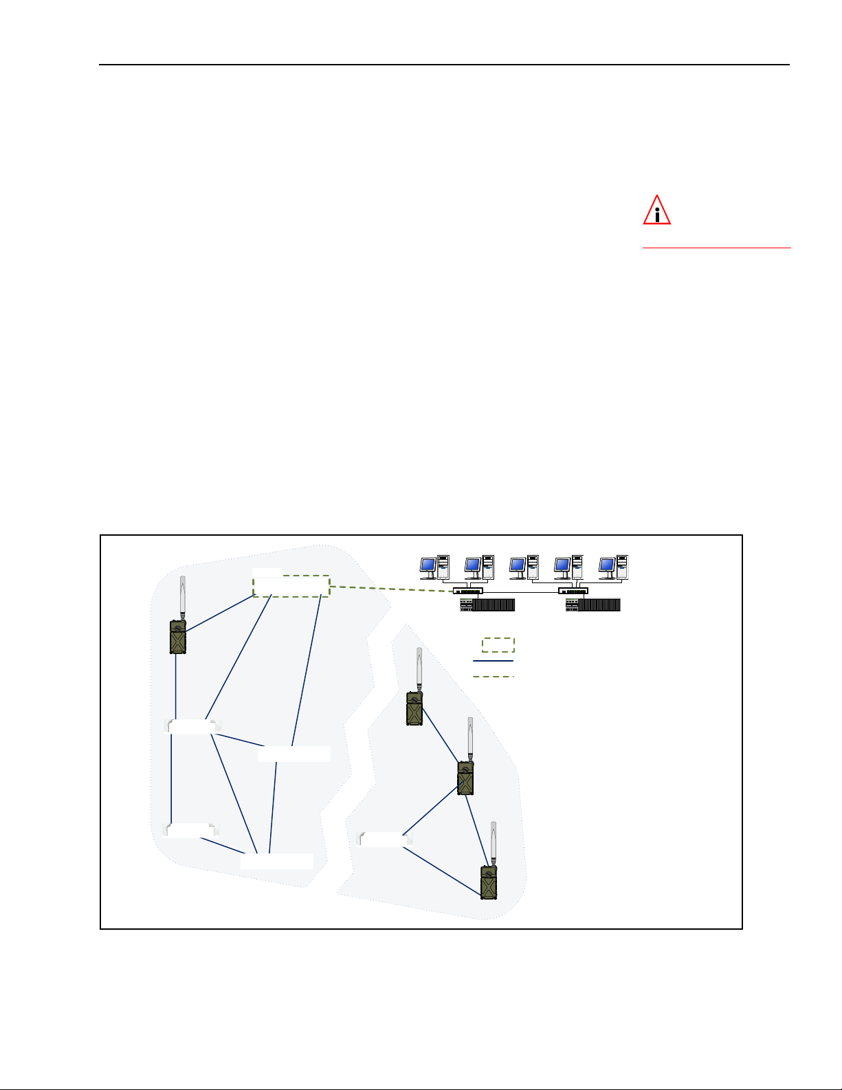
1.4.1.1 Isolated FastPath Mesh Networks
The independent RFC-4193 IPv6 mesh addressing and DNS
distribution functions embedded in FastPath Mesh enable a set
of Fortress Bridges to form a fully functioning FastPath Mesh
network as soon as they are connected.
Bridge GUI Guide: Introduction
2
Figure 1.1. Isolated FP Mesh Network with Access Network Connections
In the case of an isolated wireless FP Mesh network, as shown
in Figure 1.1, on each Bridge to be used as an MP you must, at
2. Internet Engineering Task Force Request for Comments
minimum:
License FastPath Mesh on the Bridge:
Maintain -> Licensing
on
Select FastPath Mesh for Bridging Mode:
on
Configure -> Administration
Enable the internal radio(s):
Configure -> Radio Settings
on
6
Page 22

Bridge GUI Guide: Introduction
Create a bridging BSS on (one of) the radio(s) with:
an SSID in common with the bridging BSSs on the rest
of the MPs
a Wireless Bridge setting of Enabled
on Configure -> Radio Settings -> ADD BSS
If the current MP will connect NMPs to the network, create
an Access BSS on (one of) the radio(s) with:
an SSID for NMP devices to connect to
a Wireless Bridge setting of Disabled
on Configure -> Radio Settings -> ADD BSS
The Bridge will force you to change the password of the
preconfigured administrator account when you log in for the
first time. The Bridge is not fully secure until you have also
changed passwords for the two remaining preconfigured
administrative accounts and the network Access ID from their
defaults.
Including the RFC-4193 IPv6 address FP Mesh automatically
generates, each MP can have up to sixteen IPv6 addresses. It
always has a link-local address and can always have a
manually configured IPv6 global address. If
IPv6 Auto
Addressing is Enabled (the default) and an IPv6 router is
present on the network to provide routing prefixes, additional
IPv6 addresses will be present. Each MP can also have a
manually configured IPv4 address. Refer to Section 3.4.2 for
more on IP addressing on the Bridge.
NOTE: A BSSs
bridging setting
also determines its FP
Mesh function. With
Wireless Bridge Enabled,
BSSs function as Core
interfaces; with
Bridge
Disabled they
function as Access interfaces (Section 3.3.4.3).
Wireless
To provide virtually configuration-free DHCP and DNS services
for Non-Mesh Points on the FP Mesh network, enable one (or a
few) of the DHCP servers internal to the network MPs and
leave all of their internal DNS servers enabled (the default).
The Bridge’s DNS service is used in common by IPv4 and I Pv6
networks, while the Bridge provides separate, dedicated IPv4
and IPv6 DHCP servers. Refer to Section 3.6 for more on the
Bridge’s internal DHCP and DNS servers.
1.4.1.2 Network-Attached FastPath Mesh Networks
One or more of the Mesh Points in a FastPath Mesh network
can connect the mesh to a conventional hierarchical LAN or
WAN (wide are network). An MP that serves as a bridge
between the FP Mesh network and a hierarchical network is a
Mesh Border Gateway (MBG).
The MBG interface that connects to the LAN or WAN must be
configured as an
Access interface, the MBG’s default gateway
must be a router on the hierarchical network, and route(s) to
the FastPath Mesh's subnet must be configured on the ne twork
router(s). If IPv6 network routers are configured to provide an
IPv6 global prefix, the MBG will forward it to every node in the
network (MPs and NMPs).
7
Page 23

Bridge GUI Guide: Introduction
03
03
03
03
03
03
/$1
MBG
03
03 0HVK3RLQW
MBG 0HVK%RUGHU*DWHZD\
0HVK&RUH&RQQHFWLRQ
0HVKļ+LHUDUFKLFDO&RQQHFWLRQ
$FFHVV,QWHUIDFH
ES820
ES820
ES440
ES440
ES440
ES210
ES210
ES210
03
ES820
03
ES210
If a DHCP server internal to one of the MPs is enabled to
configure the IP addresses of network NMPs, all NMPs will
have the correct default gateway address and IPv6 prefix to
automatically configure themselves without further manual
configuration.
To create a FastPath Mesh network and attach it to a
conventional hierarchical network, as shown in Figure 1.2, you
must, at minimum:
follow the steps to configure an isolated FastPath Mesh
network outlined in the preceding Section 1.4.1.1.
on each Mesh Point that will serve as an MBG:
configure the hierarchical network router as the MBG’s
default gateway: on
Configure -> Administration ->
Network Configuration.
be sure the interface that will connect to the hierarchical
network is configured as an FP Mesh Access interface.
FastPath Mesh Mode is specified for wired interfaces: on
Configure -> Ethernet Settings -> EDIT. Wireless
interfaces are automatically (and transparently)
configured as Access interfaces when
is
Disabled: on Configure -> Radio Settings -> ADD BSS.
on each router in the hierarchical network that will connect
Wireless Bridge
to an MBG, configure route(s) to the FP Mesh subnet.
Figure 1.2. Single FP Mesh Network with a Single MBG Attachment Point
8
Page 24
Bridge GUI Guide: Introduction
03
03
03
03
03
03
/$1
MBG
03
03 0HVK3RLQW
MBG 0HVK%RUGHU*DWHZD\
0HVK&RUH&RQQHFWLRQ
0HVKļ+LHUDUFKLFDO&RQQHFWLRQ
$FFHVV,QWHUIDFH
03
03
In addition to the RFC-4193 IPv6 address FP Mesh
automatically generates, the MBG is provided with a global
prefix by the network IPv6 router. If a DHCP server internal to
one of the MPs is enabled, each IPv6 node in the network can
then be reached by the public address so provided.
You can attach an FP Mesh network to a hierarchical network
by more than one MBG to provide path redundancy between
the mesh and the LAN or WAN. If one of the MBGs becomes
unavailable, the other(s) will maintain the connection.
Regardless of the number of MBGs attached to the hierarchical
network, traffic into the FP Mesh network typically flows
through only one MBG. If two (or more) MBGs are used, you
can manually split traffic between the two MBGs by IPv4
address ranges (10.1/16
->MBG1, 10.2/16->MBG2, for
example), but it will still be the case that only one MBG will
send traffic to any given FP Mesh node.
1.4.1.3 Separating and Rejoining in FastPath Mesh Networks
Mesh Points in a wireless FastPath Mesh network can
separate and rejoin smoothly, individually or in groups, as
mobile Mesh Points move in and out of range of each other.
Changes in the costs and availability of FP Mesh data paths
are propagated throughout the network.
NOTE: There is no
coordination between FP Mesh MBGs.
Figure 1.3. Single Separated FP Mesh Network
When a split forms in a mobile FP Mesh network attached to a
hierarchical network, as shown in Figure 1.3, any nodes
9
Page 25

separated from the MBG will be temporarily disconnected from
03
03
03
/$1
Mesh A
Mesh B
MBG
MBG
03 0HVK3RLQW
MBG 0HVK%RUGHU*DWHZD\
0HVK&RUH&RQQHFWLRQ
0HVKļ+LHUDUFKLFDO&RQQHFWLRQ$FFHVV,QWHUIDFH
03
03
03
03
the hierarchical network. Multiple MBGs can enable parts of the
mesh temporarily separated from each other to remain
connected to a hierarchical network, as long as there is an
MBG present among the separated group of nodes.
1.4.1.4 Bridging Loops in FastPath Mesh Networks
Bridging loops can form only when FastPath Mesh Points are
connected over both Core and Access interfaces.
In FastPath Mesh Networks with single MBG attachment point s
to the hierarchical network, such as those shown in Figure 1.4,
simultaneous Core and Access connections are not present,
and bridging loops cannot form. Although the two MBGs are
connected to the same LAN by their Access interfaces, they
are MPs in different FP Mesh networks and so are not also
connected by Core interfaces.
Bridge GUI Guide: Introduction
Figure 1.4. Two FP Mesh Networks, One MBG Attachment Point Each, Connected to a Single Access Network
When a FastPath Mesh network is attached to a hierarchical
network by two (or more) Mesh Border Gateways, the Mesh
Points serving these roles are connected to each other b oth by
their Core interfaces and by the Access interfaces connecting
them to the hierarchical network. FastPath Mesh detects and
prevents the loop that would otherwise form over these
connections:
Among the many MPs that detect a loop, only the MP with
the lowest MAC address will forward mesh traffic received
10
Page 26

on the Access interfaces on which the loop has been
/$1
Mesh A
Mesh B
MBG A2
MBG A1
MBG B1
MBG B2
03 0HVK3RLQW
MBG 0HVK%RUGHU*DWHZD\
0HVK&RUH&RQQHFWLRQ
0HVKļ+LHUDUFKLFDO&RQQHFWLRQ$FFHVV,QWHUIDFH
03
03
03
03
03
detected.
Only the MP so chosen as the forwarder will advertise
NMPs discovered on these Access interfaces.
Because only one MBG in a given FP Mesh network will
actively pass traffic to and from the hierarchical network,
multiple MBGs can be present in multiple FP Mesh networks
attached to the same LAN, as shown in Figure 1.5.
Bridge GUI Guide: Introduction
Figure 1.5. Two FP Mesh Networks, Two MBGs Each, Connected to a Single Access Network
1.4.1.5 Traffic Duplication in FastPath Mesh Networks
Although you can attach more than one FP Mesh network
simultaneously to more than one LAN, configurations in which
separate hierarchical networks are “bridged” by multiple FP
Mesh networks will necessarily generate duplicate traffic, as
shown in Figure 1.6.
11
Page 27

Bridge GUI Guide: Introduction
LAN 2
03 0HVK3RLQW
MBG 0HVK%RUGHU*DWHZD\
0HVK&RUH&RQQHFWLRQ
0HVKļ+LHUDUFKLFDO&RQQHFWLRQ
$FFHVV,QWHUIDFH
Mesh A
Mesh B
LAN 1
VHQGHU WDUJHW
'XSOLFDWH7UDIILF
MBG B2
MBG A1
MBG A2
MBG B1
03
03
03
03
03
03
Figure 1.6. Traffic Duplication in Two FP Mesh Networks Attached to Separate Access Networks
Avoid such configurations if traffic duplication is undesirable in
your environment.
1.4.2 STP Mesh Network Deployments
Fortress Bridges can be deployed in mesh networks managed
by Spanning Tree Protocol without any additional features
licensing.
When
STP is selected for Bridging Mode (the default), the
Bridge can be used as a node in an STP-managed mesh
network while—on a separate BSS—also acting as an AP
(access point) to WLAN client devices within range.
12
Page 28

Bridges configured to be able to connect to one another
LAN
WLAN
...rear-panel
grounding stud
to earth
ground
WAN
port
mast-
mounted
ES520
STP Root
WLAN
...to PoE power
PoE adapter
(implementation dependent on lightning arrestor)
automatically form mesh networks.
Bridge GUI Guide: Introduction
Figure 1.7. STP Mesh Network Deployment
At their default settings, the Bridge with the lowest MAC
address will serve as the STP root. Alternatively, you can
configure the order in which networked Bridges will assume the
role of STP root, if the existing root is lost, by specifying the
Bridge Priority order on individual Bridges in an STP network.
One or more of the linked Bridges (or network nodes) can also
be configured to connect the mesh network to a LAN and/or to
serve as a WLAN AP for compatibly configured wireless clients
within range. Figure 1.7 shows an STP mesh network in which
all connected nodes are serving as WLAN APs and the STP
root node is attached to a LAN.
NOTE: Refer to
Section 3.2.2 for
more on STP bridging
and configuring
Priority.
Bridge
13
Page 29

1.4.3 Point-to-Point Bridging Deployments
remote hardware
modem
satellite uplink
management laptop
wireless bridging link
...to power
Ethernet
Ethernet
The Bridge can be deployed as a conventional wireless Bridge
to connect two separately located LANs (local area networks),
for example, or to link remotely located hardware to the local
network for system management and data upload, as shown in
Figure 1.8).
Bridge GUI Guide: Introduction
Figure 1.8. Point-to-Point Wireless Bridging Deployment
As long as the LAN or WAN to which the Bridge is connecting
does not require STP to be enabled, Bridges can be deployed
in point-to-point (two-node) bridging configurations without any
link management (with a
Bridging Mode setting of Off).
If more than two Bridges will be networked, Fortress strongly
recommends using FastPath Mesh (if licensed) or STP link
management.
1.4.4 Wireless Client ES210 Bridge Deployments
An ES210 Bridge can be dedicated to operate as a standard
802.11 wireless client by configuring a single station (STA)
interface on its single internal radio.
ES210 Bridges operating as wireless client devices can be
integrated into Bridge-secured network deployments as any
WLAN client would be: connecting to the WLAN (or access
network) through another Bridge acting as a network AP (or
configured with an access interface).
14
Page 30

1.5 Compatibility
The Fortress Bridge is fully compatible with WPA and WPA2
enterprise and pre-shared key modes and with Fortress Secure
Client versions 2.5.6 and later.
In addition or as an alternative to the Bridge’s native
authentication service, the Bridge can be used with an external
RADIUS server. Supported services include:
Microsoft® Windows Server 2003 Internet Authentication
Service® (IAS)
freeRADIUS version 2.1 (open source)
Bridge GUI Guide: Introduction
15
Page 31

Bridge GUI Guide: Administrative Access
Chapter 2
Bridge GUI and Administrative Access
2.1 Bridge GUI
The Fortress Secure Wireless Bridge’s graphical user interface
provides access to Bridge administrative and monitoring
functions.
2.1.1 System Requirements
To display properly, the Bridge GUI requires a monitor
resolution of at least 1024 × 768 pixels and the following (or
later) browser versions:
Microsoft® Internet Explorer 7.0
Mozilla Firefox™ 2.0
2.1.2 Bridge GUI Security
Browser connections to the Bridge’s management interface are
secured via https (Hypertext Transfer Protocol Secure). GUI
access can be authenticated via the self-signed X.509 digital
certificate automatically generated by the Bridge for use by
SSL (Secure Socket Layer) and present by default in the local
certificate store. You can also import and select a different
certificate for the Bridge's SSL function (refer to Section 6.2).
You can turn off GUI access to the Bridge altogether by
disabling the user interface, requiring administrators to access
the Bridge exclusively through the CLI (refer to Section 4.1.5).
The Bridge GUI is enabled by default.
2.1.3 Logging On
Y ou ca n access the Bridge GUI from any computer with access
to the Bridge: any computer on one of the Bridge’s clear
interfaces, as well as any computer with a secure connection to
an encrypted interface.
To access the Bridge GUI:
1 Open a browser and, in the address field, enter the IP
address assigned to the Bridge’s management interface.
2 If this is the first time an administrator has logged on to the
Bridge and you agree to the terms of the license
NOTE: The default
IP address is
192.168.254.254. Default
passwords for preconfigured accounts are the
accounts’ respective
user names (refer to Section 2.2.2) and must be
changed when the account is first used.
16
Page 32

Bridge GUI Guide: Administrative Access
agreement, click to accept them. (Once accepted the
agreement does not display.)
or
If an administrative logon banner has been configured
(Section 2.2.1.9)—click to accept its terms. (There is no
administrator logon banner by default.)
3 On the Logon to Fortress Security System screen, enter a
Username and Password.
valid
4 Click LOGON.
Figure 2.1. Bridge GUI
5 If prompted to do so, en ter and confirm a new p assword for
the account and click
You will be prompted to create a new password if:
You are logging on to the Bridge for the first time.
The account password has expired or has been expired
for non-conformance (refer to Section 2.2.1.7).
The User must change password: Yes option is in effect
for the account you are trying to log on (Section 2.2.2).
You can optionally view current password complexity
requirements by clicking
bottom of the
Logon
screen, all platforms
Create a new password dialog.
SUBMIT.
Complexity Requirements at the
NOTE: Default
complexity requirements force passwords to be changed on
all three preconfigured
accounts when the accounts are first used. If
password requirements
are changed to permit
the defaults, first-time
logons to
and Logviewer will not
force password changes.
Maintenance
If Pass. Dictionary is enabled (refer to Section 2.2.1.8), new
passwords are checked against the list of words used by
the function. You can pre-check the password against the
list by clicking
message
the check;
check and cannot be used. By default, the
dictionary check is not in effect, and it is labeled
6 If you were prompt ed to creat e a new password, the Logon
Pass. Dictionary: CHECK PASSWORD. The
Not Blacklisted will be returned if the entry passes
Blacklisted! indicates that the entry failed the
password
disabled.
to Fortress Security System screen displays again: re-enter
the account
LOGON.
Username, enter the new Password, and click
NOTE: You can
view but not edit
the list against which
passwords are checked
by clicking
tionary: VIEW.
Password Dic-
17
Page 33

Bridge GUI Guide: Administrative Access
Two administrators with Administrator-level privileges (refer to
Section 2.2.2.3) cannot be logged on the Bridge at the same
time.
If you are trying to log on to an
when another such session is active, you will have the option of
forcibly ending the active session and proceeding with the
logon, or choosing
preserve the first session. Click
choice.
Figure 2.2. Bridge GUI
Access configuration settings through the menu links under
Configure on the left of all Bridge GUI screens. Monitoring
functions are available under
diagnostic tools under
Administrator-level account
Cancel Logon from the dropdown to
CONTINUE to execute your
Logon
screen when the account is active, all platforms
Monitor, maintenance and
Maintain.
2.1.4 Using Bridge GUI Views
The Bridge GUI initially opens in Simple View, which displays
an abbreviated set of items under the main menu headings on
the left side of the page and provides a limited set of
configuration settings on
To access the complete Bridge GUI, click
upper right corner of any page. The Bridge GUI Advanced View
includes additional items under the
menu headings and provides full access to configuration
settings. In Advanced View, the button in the upper right corner
changes to
Figure 2.3. Bridge GUI
For Administrator-level accounts, Advanced View-selection is
persistent over subsequent log-ons and reboots. The
View
button is absent altogether when you are logged into a
Log Viewer-level account, where it would serve no purpose
SIMPLE VIEW.
VIEW
buttons, all platforms
Configure screens.
ADVANCED VIEW in the
Configure and Maintain main
Advanced
18
Page 34

(refer to Section 2.2.2.3 for more information on account roles
and access).
On a screen common to both views, you can toggle between
the two views of the screen. If you are viewing a screen
exclusive to the Advanced View and you click
Bridge GUI will return the main page for the function or, if no
such page exists in Simple View, the
screen.
2.1.5 Accessing Bridge GUI Help
Access the table of contents for Bridge GUI help by clicking
HELP in the upper right corner of every page. For help with the
screen you are currently viewing, click
upper right of the screen.
2.1.6 Logging Off
To log off the Bridge GUI, click LOGOFF, in the upper right
corner of the screen.
If you simply close the browser you have used to access the
Bridge GUI, you will not be logged off completely. Although you
must re-open you browser and log back on to the Bridge in
order to regain access to the same account, the previous
administrative session persists until it times out or, at the point
of logging back in to the account, you opt to end it.
Bridge GUI Guide: Administrative Access
SIMPLE VIEW, the
Monitor -> Connections
More Information in the
By default, the Bridge is configured to end administrative
sessions after 10 minutes of inactivity, automatically logging
the administrator off. You can reconfigure the global
administrative
Session Idle Timeout (refer to Section 2.2.1.4).
2.2 Administrative Accounts and Access
There are three levels of permissions for administrative
accounts on the Bridge, determined by
Administrator account users have unrestricted access to
management functions and system information on the
Bridge.
Maintenance account users can view complete system and
configuration information and perform a few administrative
functions but cannot make configuration changes beyond
changing their own passwords (Section 2.2.2.11), if
permitted (the default).
Log Viewer account users can view only high-level system
health indicators and only those log messages unrelated to
configuration changes. If permitted (the default), they can
also change the password for the account.
For more detail on account privileges refer to Section 2.2.2.3.
Role assignment:
NOTE: The precon-
figured
ministrator
corresponds to the
Crypto Officer role as
defined by Federal Information Processing
Standards (FIPS) 140-2.
admin, Ad-
-level, account
By default, one of each administrative account type is present
in the Bridge’s local administrator database, with the
19
Page 35

Bridge GUI Guide: Administrative Access
predetermined user names: admin, maintenance, and logviewer,
respectively . Administrative roles are described in greater detail
in Section 2.2.2.3.
Default passwords for preconfigured accounts are the same as
their user names.
The first time you log on to the
admin account, you will be
forced to enter a new password of at least 15 characters.
Administrative password requirements are global and
configurable: refer to Section 2.2.1.8. The default complexity
requirements will force the passwords to be changed on all
three preconfigured accounts when the accounts are first used.
If password requirements are changed so that the default
passwords are acceptable, however, administrators logging on
to the
Maintenance and Logviewer accounts for the first time,
will not be forced to change these account passwords from
their defaults. All default passwords should nonetheless be
changed in order to fully secure the Bridge’s management
interface.
An administrator logged on to an Administrator-level account
can specify a number of global administrative account settings.
In Advanced View, you can also add up to ten additional
administrative accounts, as well as reconfigure individual
account settings and delete accounts.
Global administrative account settings are covered in Section
2.2.1 (below). Individual administrative account management is
covered in Section 2.2.2.
2.2.1 Global Administrator Settings
A number of configurable parameters apply globally to
administrative accounts’ logon behaviors and passwords and
to administrator authentication. View the these settings through
Configuration -> Security -> Logon Settings.
NOTE: Preconfig-
ured accounts cannot be deleted.
NOTE:
Except for
Session Idle Timeout
changes, which take
effect immediately,
changes to global
Settings
the next administrator
logon.
are applied at
Logon
Figure 2.4. Simple View
Logon Settings
frame, all platforms
2.2.1.1 Maximum Failed Logon Attempts
You can configure how many times an administrator can try
unsuccessfully to log on to one of the Bridge’s administrative
accounts before the account is subject to the Bridge’s currently
20
Page 36

configured lockout behavior. Numbers from 1 to 9 are
accepted;
3 is the default.
2.2.1.2 Failed Logon Timeout
The
Failed Logon Timeout setting specifies the number of
seconds that must elapse after a failed logon attempt before
the same administrator can successfully log on with valid
credentials.
If an administrator enters valid credentials before the specified
number of seconds have elapsed, the action is interpreted as
another failed logon attempt and the timeout counter resets.
You can set
a setting of
Failed Logon Timeout from 0 (zero) to 60 seconds;
0 disables the function (no delay between logon
attempts will be enforced). The default
5 seconds.
2.2.1.3 Lockout Behavior
You can set the length of time an administrator will remain
locked out after reaching the specified maximum logon
attempts in
Lockout Duration.
Bridge GUI Guide: Administrative Access
Failed Logon Timeout is
NOTE:
The lock-
out feature applies
only to remote logon at-
Bridge
tempts. The
unlock
always be executed via a
physical connection to
the
is never locked. Refer to
the
command can
Console
CLI Software Guide
port, which
CLI
.
Alternatively , by enabling
the Bridge to keep the account locked until you have logged on
to the Bridge GUI through an
unlocked it.
If there is no other
Administrator-level account available, you
can unlock the account only through a direct, physical
connection to the Bridge’s
unlock command. Administrative access to the Console port is
never locked. Refer to the
Administrator accounts are locked when you exceed the
maximum permitted number of failed logon attempts (Section
2.2.1.1) on the account. Attempts to log on fail when you
supply invalid credentials and when you neglect to allow the
specified period between failed attempts (Section 2.2.1.2).
Refer to Section 2.2.2.12 for instructions on unlocking an
administrative account in the Bridge GUI.
2.2.1.4 Session Idle Timeout
By default, administrative sessions time out after 10 minutes of
inactivity. You can disable administrative session timeouts with
Session Idle Timeout setting of 0 (zero) or reconfigure the
a
timeout period in whole minutes between
Permanent Lockout you can configure
Administrator-level account and
Console port, with the Bridge CLI’s
CLI Software Guide.
1 and 60.
NOTE: The idle
timeout setting for
local administrator accounts is independent
of timeout settings for
network users and connecting devices (Section
4.4).
2.2.1.5 Show Previous Logon
When
Show Previous Logon is Enabled, the date and time the
current administrator last logged on and the IP address and
user interface (GUI or CLI) used to do so are displayed at the
top of the first page displayed by the Bridge GUI (
Connections for initial Administrator- or Maintenance-level
Monitor ->
21
Page 37

log-ons and Monitor -> Event Log when Log Viewer accounts
first access the Bridge GUI). The feature is
Show Previous Logon is present only in Advanced View (refer to
Section 2.1.4).
2.2.1.6 Authentication Method and Failback
Bridge GUI Guide: Administrative Access
Disabled by default.
By default, administrative Usernames and passwords are
authenticated by the
Local administrator authentication
service—a designated service running on the Bridge itself and
separate from the local user authentication service configured
Configure -> RADIUS Settings -> Local Server (refer to
on
Section 4.3.2).
Alternatively, you can reconfigure the Bridge to send
administrators’ logon credentials to a Remote Authentication
Dial-In User Service (
the RADIUS server internal to the current Bridge
the RADIUS server internal to another Bridge on the
RADIUS) server, which may be any of:
network
a third-party RADIUS server running on the network
The service(s) available are determined by the Bridge’s
configuration for authentication servers as determined by the
settings on
When a Fortress or a third-party
Configure -> RADIUS Settings.
RADIUS server is used to
evaluate administrator logon credentials, locally configured
logon settings and password rules do not apply. Administrative
logon behavior and password rules are determined by the
account settings in effect on that
RADIUS server.
NOTE: Adminis-
trators added in
the external authentication service are
by the Bridge, but cannot be authenticated until their records have
been opened locally for
configuration (refer to
Section 2.2.2.8).
Learned
When the Bridge is configured to use a third-party or Fortress
RADIUS server and Authentication Failback is Enabled, the
Bridge will use its local administrator authentication service as
a backup means of authenticating administrator credentials,
should the third-party or Fortress user authentication database
become unavailable.
When
Bridge configured to use a third-party or Fortress
Authentication Failback is disabled (the default) on a
RADIUS
server for administrator authentication, and no such server is
available, administrators cannot be authenticated and logged
on to the Bridge until access to the external server is restored.
Authentication Failback is not applicable to Bridges configured
with the default
Authentication Method of Local.
Authentication Method and Authentication Failback are present
only in Advanced View (refer to Section 2.1.4).
To use the local Fortress RADIUS Server
to authenticate administrators:
Except for steps 7 through 11, which can be performed at any
time, you
must follow the steps of the procedure below in the
order given.
22
Page 38

Bridge GUI Guide: Administrative Access
1 Log on to the Bridge GUI through an Administrator-level
account and select
of the page, then
ADVANCED VIEW in the upper right corner
Configure -> RADIUS Settings from the
menu on the left.
2 Click to access the Local Server tab, and in the Local
Authentication Server frame:
In Administrative State, click to select Enabled.
In Administrator Auth, click to select Enabled.
For help with other settings on this screen refer to Section
4.3.2.
Figure 2.5. enabling local administrator authentication, all platforms
3 Click APPLY in the upper right of the screen.
4 Select Configure -> Security from the menu on the left.
5 In the Security screen’s Logon Settings frame:
In Authentication Method, select RADIUS from the
dropdown.
In Auth Failback, optionally click to select Enabled.
For help with other settings in this frame refer to the rest of
this section.
CAUTION: For-
tress strongly recommends selecting
Enabled for Auth Fail-
back
to insure against
administrative lockout
in the event of network
disruptions or administrator error.
Figure 2.6. enabling administrator authentication failback, all platforms
6 Click APPLY in the upper right of the screen.
23
Page 39

Bridge GUI Guide: Administrative Access
7 Select Configure -> RADIUS Settings from the menu on the
left.
8 Click to access the Local Server tab and in the User Entries
frame, click
9 In the Edit Local Authentication screen’s User Database
Entry
frame:
In Username, enter a user name of at least one (1)
NEW USER.
alphanumeric characters.
In New Password/Confirm Password, enter a password
that confirms to current password requirements
(Section 2.2.1.8).
In Role, select Administrator from the dropdown.
For help with other settings in this frame refer to Section
4.3.3.1.
Figure 2.7. creating an administrator account on the local authentication server, all platforms
10 Click APPLY in the upper right of the screen.
11 Repeat steps 8 through 2.7 for any additional
administrators you want to configure.
To use a remote Fortress
RADIUS
Server
to authenticate administrators:
To use a RADIUS server running on another Bridge on the
network to authenticate administrators for the local Bridge, you
must configure an entry for the server on the local Bridge’s
Authentication Servers page, specifying Fortress Auth as its
Server Type and Admin as a supported Auth Type (refer to
Section 4.3.1).
Only administrators with user accounts (configured for the
Administrator) on the remote Bridge will be able to
of
Role
authenticate through its user authentication service (refer to
Section 4.3.3.1).
To use a third-party RADIUS Server
to authenticate administrators:
To use a third-party RADIUS server for administrator
authentication, it must be configured to use Fortress’s VendorSpecific Attributes for
Password-Expired
Fortress-Administrative-Role and Fortress-
, provided in the dictionary.fortress
configuration file included on the Bridge software CD and
available for download at
www.fortresstech.com/support/.
24
Page 40

Consult your RADIUS server documentation for information on
configuring the service. You must additionally configure an
entry for the server on the Bridge’s
Configure -> RADIUS Settings-> Server List), specifying 3rd
(
Party RADIUS
Type
for the service (refer to Section 4.3.1 for more information
as its Server T ype and Admin as a supported Auth
on configuring external authentication servers for the Bridge.).
2.2.1.7 Password Expiration
You can configure the Bridge to expire administrative
passwords after a specified period and to warn administrators a
specified number of days before the password expires.
Bridge GUI Guide: Administrative Access
Authentication Servers list
Password expiration (
When
Pass. Expire is Enabled, you can specify a password
expiration period (
default expiration period is
Expiration Warning
Pass. Expire) is Disabled by default.
Pass. Expiration) of 1 to 365 days. The
60 days.
You can also configure the Bridge to warn administrators that
their passwords are scheduled to expire. You can set
Expire Warning from 0 to 365. An expiration warning setting of 0
Pass.
or a setting greater than the specified password expiration
period disables the function (no password expiration warning
will be issued). When a
Pass. Expiration is set, the warning **Your password will expire
soon**
Connections for Administrator-level accounts) whenever an
appears at the top of the first screen displayed (initially
Pass. Expire Warning smaller than
administrator logs on, beginning the specified number of days
before administrators are forced to change their passwords.
The warning does not persist after the administrator navigates
away from the first page viewed. (If
Expire Warning
are set to the same value, the warning will
Pass. Expiration and Pass.
display whenever an administrator logs on.)
Nonconformance Expiration
If you change the rules for administrative passwords (refer to
Section 2.2.1.8), some existing passwords may not conform to
the new requirements.
Expire Nonconforming Pass. allows you
to choose whether such passwords will expire at the time the
rules change (
next scheduled expiration date (
Nonconforming Pass.
Enabled) or will be allowed to persist until the
Disabled). By default, Expire
is Enabled: administrators are forced to
change nonconforming passwords the first time they log on
after the rules for passwords have changed.
Expire Nonconforming Pass. is present only in Advanced View
(refer to Section 2.1.4).
25
Page 41

2.2.1.8 Password Requirements
Bridge GUI Guide: Administrative Access
The Bridge will not accept new passwords that do not meet
specified requirements. If you specify new requirements that
existing passwords do not meet, nonconforming passwords are
treated according to the
Expire Nonconforming Passwords
setting (described in Section 2.2.1.7).
Configured complexity requirements apply equally to
administrative passwords and to those of locally authenticated
network users (Section 4.3.3.1).
You can apply up to nine rules for administrative and local user
passwords:
Pass. Minimum Length - Passwords must be at least the
specified number of characters long. You can specify
values from
Pass. Minimum Capitals - Passwords must contain at least
8 to 32 characters. The default is 15.
the specified number of uppercase letters. You can specify
values from
0 (zero) to 5; a 0 value (the default) allows
passwords containing no uppercase letters.
Pass. Minimum Lowercase - Passwords must contain at
least the specified number of lowercase letters. You can
specify values from
0 (zero) to 5; a 0 value (the default)
allows passwords containing no lowercase letters.
Pass. Minimum Numbers - Passwords must contain at least
the specified number of numerals. You can specify values
from
0 (zero) to 5; a 0 value (the default) allows passwords
containing no numerals.
Pass. Minimum Punctuation - Passwords must contain at
least the specified number of symbols from the set:
# $ % ^ & *( ) _ - + = { } [ ] | \ : ; < > , . ?
/
(excludes double and single quotation marks). You can
specify values from
0 (zero) to 5; a 0 value (the default)
~ ! @
allows passwords containing no symbols.
NOTE: Passwords
do not need to be
unique.
Pass. Minimum Delta - Passwords must contain at least the
specified number of changed characters, as compared to
the previous password. You can specify values from
(zero) to
Depth
5. A 0 value disables the check: if Pass. History
(below) is also Disabled (the default), the same
0
password can be used consecutively, without any change
(provided it still conforms to the rest of the rules in effect).
Pass. Minimum Delta is disabled by default.
Pass. Consecutive Characters - Passwords can/cannot
contain consecutive repeated characters or consecutive
characters in ascending or descending numeric or
alphabetic order. When
Disabled, passwords cannot include the character pairs 98
ab, for examples. When it is Enabled (the default),
or
Pass. Consecutive Characters is
passwords can contain consecutive characters in numeric
or alphabetic order.
NOTE: Pass. Minimum Delta
Pass. History Depth are
tracked separately for
each administrative account.
and
26
Page 42

Bridge GUI Guide: Administrative Access
Pass. Dictionary - Passwords can/cannot match words in
the dictionary . When
Pass. Dictionary is Enabled, passwords
are checked against a list of English words, and the
password is rejected if a match is found. When it is
Disabled
(the default), passwords can contain the words on the list.
You can view but not edit the word list:
Admin Users -> EDIT|NEW USER -> Pass. Dictionary -> VIEW.
Pass. History Depth - Passwords cannot be reused until the
Configuration ->
specified number of new passwords have been created.
You can specify values of
the check: if
Pass. Minimum Delta (above) is also Disabled
0 (zero) to 10. A 0 value disables
(the default), the same password can be used
consecutively, without any change (provided it still
conforms to the rest of the rules in effect).
is disabled by default.
Depth
Pass. History
Password requirements settings are present only in Advanced
View (refer to Section 2.1.4).
To configure global administrative account settings:
The Bridge GUI’s Logon Settings are shown in Advanced View
below.
Figure 2.8. Advanced View
Table 2.1 shows which Administrator Logon settings appear in
the two GUI views.
Logon Settings
frame, all platforms
27
Page 43

Bridge GUI Guide: Administrative Access
Table 2.1. Global Administrator Logon Settings
Simple & Advanced Views Advanced View Only
Max Failed Logon Tries Show Previous Logon
Failed Logon Timeout Authentication Method
Permanent Lockout Authentication Failback
Lockout Duration Expire Nonconforming Pass.
Session Idle Timeout Pass. Min. Length
Pass. Expire Pass. Min. Capitals
Pass. Expiration Pass. Min. Lowercase
Pass. Expire Warning Pass. Min. Numbers
Pass. Min. Punctuation
Pass. Min. Delta
Pass. Consec. Characters
Pass. Dictionary
Pass. History Depth
1 Log on to the Bridge GUI through an Administrator-level
account and select
Configure -> Security from the menu on
the left.
2 If you are configuring one or more Advanced View settings
(see Table 2.1), click
corner of the page. (If not, skip this step.)
3 In the Security screen’s Logon Settings frame, enter new
values for those settings you want to configure (described
in sections 2.2.1.1 through 2.2.1.8).
4 Click APPLY in the upper right of the screen (or RESET
screen settings to cancel your changes).
2.2.1.9 System Messages
Comment field in the System Messages frame on Configure
The
-> Administration is intended as a user-configured informational
field. The
Comment is displayed nowhere else.
You can configure a
administrator logon screens.
When a logon banner is present, administrators are prompted
to click to accept its conditions before they are permitted to
proceed with the logon.
There is no
Warning Banner configured by default.
ADVANCED VIEW in the upper right
Warning Banner for display on the Bridge’s
28
Page 44

Bridge GUI Guide: Administrative Access
Figure 2.9.
Logon Banner
on the Bridge GUI
Logon Screen
screen, all platforms
To configure a comment or administrator logon banner:
1 Log on to the Bridge GUI through an Administrator-level
account and select
Configure -> Administration from the
menu on the left.
2 Scroll down to the System Messages frame and:
Optionally enter information into the Comment field.
and/or
In the Warning Banner field enter or paste a message of
up to 2000 characters or click
UPLOAD BANNER FILE to
upload text from an existing file.
3 Click APPLY in the upper right of the screen (or RESET
screen settings to cancel your changes).
Figure 2.10.
System Messages
frame, all platforms
29
Page 45

To eliminate an existing logon banner, delete all content from
Warning Banner field and APPLY the change.
the
2.2.2 Individual Administrator Accounts
Up to thirteen usable administrative accounts can be present
on the Bridge’s local administrator database at one time.
Three of these are preconfigured with the fixed user names:
admin, maintenance and logviewer, reflecting the default
administrative
reconfigured (refer to Section 2.2.2.9), preconfigured
administrative accounts cannot be deleted.
Role of each account. While they can be
Bridge GUI Guide: Administrative Access
Figure 2.11. Simple View
In Advanced View, you can add up to ten additional local
administrative accounts and configure additional account
parameters for both pre-configured and manually created
accounts.
On Bridges configured to authenticate administrators through a
third-party or Fortress
an additional ten
on the
Admin Users page.
Learned administrative accounts are not immediately usable to
locally authenticate administrators. In order to be usable for
local authentication, accounts for
be converted to configured accounts on the local administrator
database (refer to Section 2.2.2.8).
converted to configured accounts are retained in the local
administrator database and count toward the maximum total of
thirteen configured accounts.
Although the credentials associated with a
initially learned by the local administrator database from an
administrative account on another authentication service, the
two accounts are not linked in any way after the
account has been converted to a configured account.
Administrator Settings
RADIUS server (refer to Section 2.2.1.6),
frame, all platforms
Learned administrative accounts can appear
Learned administrators must
Learned accounts
Learned account are
Learned
NOTE: In order for
any account in the
local administrator database to authenticate
an administrator, the
Bridge must be using
the local administrator
database for that purpose (whether it has
been configured for
administrator au-
cal
thentication or has
failed back to the local
administrator database
(Section 2.2.1.6).
Lo-
30
Page 46

2.2.2.1 Administrator User Names
Bridge GUI Guide: Administrative Access
At the time a new administrative account is created, you must
provide a
Username. Once established, the Username
associated with an administrative account cannot be changed.
Administrator user names must be unique on the Bridge. They
are case sensitive, can be from 1 to 32 characters long, and
can include spaces and any of the symbols in the set:
$ % ^ & *( ) _ - + = { } [ ] | \ : ; < > , . ? /
(excludes double and single quotation marks).
An administrative account with a
Username configured for the associated administrator in the
the
third-party or Fortress
RADIUS server (refer to Section 2.2.2.8).
You can create new administrative accounts only in Advanced
View.
2.2.2.2 Account Administrative State
Preconfigured and newly added administrative accounts are
Enabled by default. If you change an account’s Administrative
State to Disabled, it will no longer be usable. If the associated
administrator attempts to log on to a
Logon to Fortress Security System screen will be returned with
an error message. If you re-enable the account, the
administrator will be allowed to log on normally.
~ ! @ #
Learned state of Yes acquires
Disabled account, the
NOTE: In Ad-
vanced View, the
Username for any ac-
count listed in
trator Settings
Detailed Statistics dialog
for the account. Refer to
Section 5.2 for more information.
Adminis-
links to a
At least one enabled
present on the Bridge at all times. You will not therefore be
allowed to disable an
such account on the Bridge.
Y ou can create new administrative accounts and ed it them only
in Advanced View, but you can change the
preconfigured accounts in both views.
2.2.2.3 Administrative Role
An administrative account can be configured for one of three
possible administrative roles:
Administrator accounts provide unrestricted access to the
Bridge.
Administrator-level users can configure all functions
and view all system and configuration information on the
Bridge.
Maintenance accounts provide view-only access to
complete system and configuration information but no
reconfiguration access. A maintenance administrator’s
execution privileges are confined to using the network
diagnostic tools on
Clients and controller device sessions, rebooting the
Bridge, and generating a support package.
Log Viewer accounts provide view-only access to high-level
system health indicators and any log messages unrelated
Administrator-level account must be
Administrator-level account if it is the only
Admin State of
NOTE: Log Viewer
and Maintenance
administrators can
change their own passwords, provided their
account passwords are
not locked (refer to Section 2.2.2.7).
Maintain -> Network, resetting Secure
31
Page 47

Bridge GUI Guide: Administrative Access
to configuration changes. Log Viewer-level accounts have
no execution privileges on the Bridge.
Only one
Administrator-level account can be active on the
Bridge at one time. Their limited permissions allow multiple
Maintenance-level and Log Viewer-level accounts to be active
on the Bridge at the same time. Only one active session per
administrative account is supported, regardless of
Role.
You can reconfigure the
Role of any administrative account,
including the preconfigured accounts.
If you downgrade the role of the
Administrator-level account you
are currently logged on through, you will be able to finish the
session with full permissions. The role change takes effect
when you next log on to the account.
At least one enabled
Administrator-level account must be
present on the Bridge at all times. You will not therefore be
allowed to reconfigure the
Role of an Administrator-level
account if it is the only such account on the Bridge.
You can create administrative accounts and edit an account’s
Role only in Advanced View.
2.2.2.4 Administrator Audit Requirement
Whether and how an administrative account is subject to audit
logging is configured in the
Audit field. Three options are
available at the individual account level:
Required (the default) - Activity on the account will be
included in the audit log.
Prohibited - Activity on the account will not be included in
the audit log.
Auto - Account activity will be treated by the audit logging
function according to the global settings in
Logging (refer to Section 4.6.2).
You can create administrative accounts and edit an account’s
Audit setting only in Advanced View.
Configuration ->
NOTE: An individ-
ual account’s
setting overrides global
Logging settings.
Audit
2.2.2.5 Administrator Full Name and Description
An administrative account does not require a
Description to be entered for the administrator.
If you choose to use these fields, they accept up to 250
alphanumeric characters, symbols and/or spaces.
You can create and edit administrative accounts only in
Advanced View.
You can create administrative accounts and edit an account’s
Full Name and Description only in Advanced View.
2.2.2.6 Administrator Interface Permissions
You can control which of the Bridge’s management interfaces
an administrative account can access.
Full Name or a
32
Page 48

Bridge GUI Guide: Administrative Access
Console - The account can access the Bridge CLI through a
direct, physical connection to the Bridge’s
(refer to the
Web - The account can access the Bridge GUI through a
CLI Software Guide).
Console port
browser connected to the Bridge’s IP address (refer to
Section 2.1.3).
SSH - The account can access the Bridge CLI through a
Secure Shell terminal session (refer to the
Guide
).
CLI Software
Interfaces are independently selectable in any combination. By
default, all three are selected so that accounts can use any of
them to access the Bridge. Clearing an option’s checkbox will
deselect it, preventing access through the deselected interface
for that account. Clearing all three
Interface Permissions
checkboxes effectively disables the account.
You can create new administrative accounts only in Advanced
View, but you can change interface permissions for the three
preconfigured accounts in Simple View.
NOTE: SSH must
be enabled on the
Bridge before an administrative account configured for SSH access can
log on to the Bridge CLI
remotely (refer to Section 4.1.6 and/or the CLI
Software Guide).
2.2.2.7 Administrator Passwords and Password Controls
You must configure a password for an administrative account
at the time the account is created.
Passwords must conform to the rules in effect on the Bridge as
configured in
Security settings (refer to Section 2.2.1.8)
You can also view current password complexity requirements
by clicking
More Information in the upper right of the Edit Admin
Users screen and then Password Complexity Settings.
An administrative account with a
Learned state of Yes acquires
the password configured for the associated administrator in the
external RADIUS server (refer to Section 2.2.2.8). This
password need not conform to locally configured rules.
You can create and edit administrative accounts only in
Advanced View, but, as long as you are logged on to an
Administrator-level account, you can enable/disable the three
preconfigured accounts in Simple View and change their
passwords and interface permissions. (Refer to Section
2.2.2.11 for information on changing passwords from lower
level administrator accounts.)
Locking Passwords
By default, passwords are not locked, allowing administrators
Maintenance and Log Viewer accounts to change their own
with
passwords (refer to Section 2.2.2.11). When
Yes is selected for
Password is Locked, passwords cannot be changed. If an
administrator attempts to change a locked password, the
Password screen will be returned with the error message:
Password is locked against any changes.
Edit
NOTE: Default
passwords for preconfigured accounts are
the same as their user
names (
nance
should be changed
when the Bridge is installed.
tive account’s
covered in Section
2.2.2.3.
admin, mainte-
, logviewer) and
NOTE: Configur-
ing an administra-
Role is
33
Page 49

Bridge GUI Guide: Administrative Access
The same message will be returned for an Administrator-level
account if the administrator tries to change the password when
the password is locked. Because
can change the
Password is Locked setting for any account, it is
Administrator-level accounts
impossible to effectively lock passwords on these accounts
(although the administrator will have to select
is Locked and APPLY the reconfiguration before changing the
No for Password
password).
You can lock administrative account passwords only in
Advanced View.
Forcing Password Changes
You can force an administrator to change an account’s
password the next time s/he logs on to the account by selecting
Yes for User must change password.
After the administrator has successfully changed the p assword
and logged on, the function will reset to
password: No.
User must change
You cannot force a password change on an account when the
account’s password is locked. If both
User must change password are set to Yes, the administrator will
Password is Locked and
be allowed to log on without changing the account password,
and
User must change password will reset to No without effect.
NOTE: Preconfig-
ured accounts
force their default passwords to be changed
when the accounts are
first accessed.
You can force administrative account password changes only
in Advanced View.
2.2.2.8 Adding Administrative Accounts
You can create new administrative accounts from an existing
Administrator
-level account. When the Bridge is configured to
use the local administrator database to authenticate
administrator credentials (
Authentication Method: Local, refer to
Section 2.2.1.6), manual creation is the only way to add
administrative accounts. (Accounts added automatically from
external authentication databases are described in the second
part of this section.)
For manually created accounts, you can automatically
generate a random password that exceeds the requirements
currently in effect (Section 2.2.1.8). Generated passwords
conform to all current complexity rules and exceed the
specified minimum length by four characters, unless the
specified minimum is fewer than four characters short of the
32-character maximum (in which cases characters are added
to total 32).
You can add administrative accounts only in Advanced View.
To add a new administrative account:
1 Log on to the Bridge GUI through an Administrator-level
account and select
ADVANCED VIEW in the upper right corner
34
Page 50

of the page, then Configure -> Administration from the menu
on the left.
2 In the Administration screen’s Administrator Settings frame,
click
NEW USER.
Figure 2.12. creating a new administrator account, all platforms
Bridge GUI Guide: Administrative Access
3 In the Account Information frame, enter at least a Username
and optionally a
Full Name and/or Description, and
configure any additional settings for the account. (Your
options are described in detail in sections 2.2.2.1through
2.2.2.6.)
4 In the Password Controls frame, establish a new password
for the account:
Click GENERATE PASSWORD to automatically generate a
password that complies with the complexity
requirements currently in effect (Section 2.2.1.8).
or
Enter a New Password that complies with the
complexity requirements currently in effect.
You can check the password against the list of words used
by the Bridge’s
Password Dictionary function by clicking
Password Dictionary: CHECK PASSWORD. The message Not
Blacklisted
will be returned if the entry passes the check;
Blacklisted! indicates that the entry failed the check and
cannot be used. If the
effect it is labeled
5 Record and secure the new password for future reference.
Password Dictionary check is not in
(disabled).
CAUTION:
record of the password for future access
to the Bridge. After the
password is applied it
cannot be queried by
any means.
Make a
You will need the password for subsequent access to the
Bridge and the network it secures.
6 Optionally, in the same frame, you can lock the password or
require the administrator to change it when s/he first logs
on (described in detail in Section 2.2.2.7.)
35
Page 51

Bridge GUI Guide: Administrative Access
You can optionally view current password complexity
requirements by clicking
of the
Settings
7 Click APPLY in the upper right of the screen (or CANCEL the
Edit Password screen and then Password Complexity
.
creation of the new account).
The new account will be listed, in Advanced View, in
Administrator Settings on Configure -> Administration.
Figure 2.13. Advanced View
When the Bridge is configured to authenticate administrators
through a third-party or Fortress user authentication database
(
Authentication Method: RADIUS), administrators who log on
successfully through a user account are automatically added to
the Bridge’s local database of administrator accounts as
Learned accounts. (Refer to Section 2.2.1.6 for more on
administrative authentication methods.)
More Information in the upper right
Administrator Settings
frame, all platforms
NOTE: You can
view but not edit
the list against which
passwords are checked
by clicking
tionary: VIEW.
tails on configuring the
Bridge
party or Fortress RADIUS server to authenticate
administrators.
Password Dic-
NOTE:
Refer to Sec-
tion 2.2.1.6 for de-
to use a third-
Up to ten such
among configured accounts on the
the local administrator database—with a
Learned accounts can be present. They appear
Admin Users page—and in
Learned status of Yes.
Learned account credentials can be authenticated only by the
third-party RADIUS server or Fortress user authentication
database on which their accounts were originally configured. A
Learned administrator cannot log on to the Bridge through the
local administrator database until you convert the account to a
locally configured account (as indicated by a
Learned state of
No).
To convert a learned account to a configured account:
1 Log on to the Bridge GUI through an Administrator-level
account and select
of the page, then
ADVANCED VIEW in the upper right corner
Configure -> Administration from the menu
on the left.
2 In the Administrator Settings frame, locate the record for the
Learned (Yes) administrator whose account you want to
convert (the
RADIUS-server user name), and click the
Username will match the administrator’s
EDIT button to the
left of the record.
You need not make any changes to the account.
NOTE: Once a
Learned account
has been converted to a
local configured account, it is completely
independent of the account in the authentication service from which
it was learned.
36
Page 52

Bridge GUI Guide: Administrative Access
3 Click APPLY in the upper right of the screen (or CANCEL the
conversion of the account).
The newly converted account will be listed, in Advanced View,
Configure -> Administration with Learned state of No, and the
on
associated administrator will be allowed to log on (with valid
credentials).
Learned user names and passwords need not meet the
Bridge’s configured requirements for local administrative
accounts.
2.2.2.9 Editing Administrative Accounts
You can reconfigure any setting for an individual administrative
account except for the
1 Log on to the Bridge GUI through an Administrator-level
account and select
of the page, then
Username.
ADVANCED VIEW in the upper right corner
Configure -> Administration from the menu
on the left.
2 In the Administrator Settings frame, click the EDIT button to
the left of the account you want to edit.
3 On the resulting Administration screen, enter new values for
those settings you want to configure. (Your options are
described in detail in sections 2.2.2.2 through 2.2.2.7.)
4 Click APPLY in the upper right of the screen (or CANCEL your
changes).
Global administrative account logon behaviors and password
requirements can be edited through
described in Section 2.2.1.
2.2.2.10 Deleting Adm inistrative Accounts
Y ou can delete any accoun t in the Advanced View
Settings
frame (Configure -> Administration), except for:
Configure -> Security, as
Administrator
NOTE: If an ac-
count is the only
Enabled Administrator-
level account present,
you cannot change its
Administrative State to
Disabled or reconfigure
its Role.
NOTE:
Changes to
the account you
are currently logged
onto will take effect the
next time you log on.
the preconfigured accounts: admin, logviewer and
maintenance
any account, if it is the only Administrator-level account with
Administrative State of Enabled present on the Bridge
an
At least one account with the
Role of Administrator (refer to
Section 2.2.2.3) must always be present and enabled on the
Bridge.
1 Log on to the Bridge GUI through an Administrator-level
account and select
of the page, then
ADVANCED VIEW in the upper right corner
Configure -> Administration from the menu
on the left.
2 In the Administrator Settings frame, click to place a check in
the box(es) to the left of the account(s) you want to
eliminate.
3 Click DELETE in the upper left of the frame.
37
Page 53

4 Click OK in the confirmation dialog (or CANCEL the deletion).
Figure 2.14. deleting an administrator account, all platforms
The account will be removed from the Advanced View
Administrator Settings frame (Configure -> Administration).
2.2.2.11 Changing Adm inistrative Passwords
Administrators with
Administrator-level accounts can change
the password of any account, including their own, as described
in sections 2.2.2.7 and 2.2.2.9.
Bridge GUI Guide: Administrative Access
Provided the password is not locked (refer to Section 2.2.2.7),
administrators with
Maintenance or Log Viewer accounts can
change their own passwords:
To change the account password from
Maintenance and Log Viewer accounts:
1 Log on to the Bridge GUI through a Maintenance-level or
Log Viewer-level account and select Configure ->
Administration from the menu on the left.
2 In the Change Your Password frame, enter a New Password
and re-enter it in
Figure 2.15. changing the password from within a
Confirm Password.
You can optionally view current password complexity
requirements by clicking
of the
Settings
Edit Password screen and then Password Complexity
.
More Information in the upper right
You can check the password against the list of words used
by the Bridge’s
Section 2.2.1.8) by clicking
PASSWORD. The message Not Blacklisted will be returned if
Password Dictionary function (refer to
Password Dictionary: CHECK
the entry passes the check;
Maintenance-
or
Log Viewer
-level account, all platforms
Blacklisted! indicates that the
NOTE: The Change
Your Password
tion does not appear on
Administration screen
the
when you are logged on
through an
level account.
the list against which
passwords are checked
by clicking
tionary: VIEW.
Administrator-
NOTE: You can
view but not edit
Password Dic-
op-
38
Page 54

entry failed the check and cannot be used. If the Password
Dictionary
3 Click APPLY in the upper right of the screen (or CANCEL the
check is not in effect it is labeled (disabled).
change).
Role configuration options for administrative accounts are
described in detail in Section 2.2.2.3.
2.2.2.12 Unlocking Administrator Accounts
You can unlock administrator accounts in Advanced View only.
Bridge GUI Guide: Administrative Access
Figure 2.16. unlocking an administrator account, all platforms
1 Log on to the Bridge GUI through an Administrator-level
account and select
of the page, then
ADVANCED VIEW in the upper right corner
Configure -> Administration from the menu
on the left.
2 In the Administrator Settings frame, click to place a check in
the box(es) to the left of the account(s) you want to unlock.
3 Click UNLOCK in the upper left of the frame.
4 Click OK in the confirmation dialog (or CANCEL the action).
The account will be unlocked and the associated administrator
will be able to log on normally (with valid credentials).
The
Lockout Duration can be set from 0 (zero) to 60 minutes; a
Lockout Duration of 0 (the default) disables the lockout function,
provided that
Permanent Lockout is Disabled (the default).
2.2.3 Administrator IP Address Access Control
You can control remote administrative access to the Bridge by
restricting the IP addresses from which administrators are
permitted to log on.
When the
those IP addresses present on the list will be permitted to
access the Bridge’s management interface remotely.
To control remote access by specified IP addresses:
1 Log on to the Bridge GUI through an Administrator-level
account and select
of the page, then
menu on the left.
Admin IP Access Control Whitelist is Enabled, only
ADVANCED VIEW in the upper right corner
Configure -> Access Control from the
NOTE: If no Admin-
istrator
-level account is available, you
can unlock an account
only through a direct,
physical connection to
the Bridge’s
port, with the Bridge
unlock command
CLI’s
(refer to the CLI Soft-
ware Guide).
CAUTION: If you
ignore the relevant
warning, you can lock
out all network access to
the Bridge by having the
administrator IP ACL
Enabled when there are
no IP addresses listed.
You can access the
Bridge in this case only
by a physical connection
to the Bridge’s
port (refer to the CLI
Software Guide)
Console
Console
39
Page 55

Bridge GUI Guide: Administrative Access
2 In the resulting screen’s Admin IP Access Control Whitelist
frame, click
NEW IP.
Figure 2.17. Advanced View
3 In the resulting Add an IP ACL Entry dialog, enter the IP
Address of the computer from which you are currently
logged on and, optionally, a
click
APPLY (or CANCEL the addition).
The IP address you added will be listed on the
Access Control Whitelist.
4 Repeat steps 2 and 3 for any additional IP addresses from
which you want to permit administrative access.
5 When you have finished adding permitted IP addresses, in
the
Admin IP Access Control Whitelist frame, in
Administrative State, click Enabled.
Figure 2.18. Advanced View
6 Click APPLY on the right of the frame.
If you navigate away from the screen without clicking
APPLY, the Administrative State will not be changed.
If you attempt to enable the
when the IP address you are currently logged on through is not
listed, a dialog warns that proceeding will lock the computer
you are currently using out of the Bridge’s management
interface.
Add an IP ACL Entry
dialog, all platforms
Description for the entry. Then
Admin IP Access Control Whitelist
Admin IP Access Control Whitelist
Admin IP
frame, all platforms
CAUTION: If your
current IP address
is not on the administrator IP ACL when you
Enable it or you delete
your address when the
list is already enabled,
and you do not
Cancel
the change when
prompted, your session
will end and your current IP address will be
blocked until it is added
to the list of permitted
addresses or the function is disabled.
Figure 2.19. Advanced View current IP address lockout dialog, all platforms
40
Page 56

A dialog will also warn you if you are deleting your current IP
address from the list when it is already enabled (after you have
cleared the usual confirmation dialog).
Unless you want to prevent management access to the Bridge
from your current IP address,
The
Admin IP Access Control Whitelist is Disabled by default,
and no IP addresses are listed.
If the
Admin IP Access Control Whitelist is Enabled when there
are no IP addresses on the list, administrative access to the
Bridge will be possible only through a direct, physical
connection to the Bridge’s
Software Guide)
.
Console port (refer to the CLI
2.2.4 SNMP Administration
In the Bridge GUI Advanced View, the Fortress Bridge can be
configured for monitoring through Simple Network
Management Protocol (SNMP) version 3.
The Fortress Management Information Bases (MIBs) for the
Bridge are included on the Bridge CD-ROM.
Bridge GUI Guide: Administrative Access
Cancel these changes.
When SNMP v3 support is enabled, the SNMP v3 user
(
FSGSnmpAdmin) access to the Bridge is authenticated via the
SHA-1 message hash algorithm as defined in RFC 2574,
based Security Model (USM) for version 3 of the Simple Network
Management Protocol (SNMPv3)
, using the specified
User-
authentication passphrase. SNMP v3 privacy is secured via the
Advanced Encryption Standard with a 128-bit key (AES-128),
using the specified privacy passphrase.
SNMP v3 support is disabled by default.
When SNMP traps are enabled, the SNMP daemon running on
the Bridge detects certain system events and sends notice of
their occurrence to a server running an SNMP management
application, the network management system (NMS), or trap
destination.
SNMP traps are disabled by default, and no SNMP trap
destinations are configured (refer to Section 2.2.4.2).
Figure 2.20. Advanced View
SNMP frame
, all platforms
41
Page 57

Bridge GUI Guide: Administrative Access
The settings that configure SNMP on the Bridge include:
SNMP v3 Support - enables/disables SNMP v3 user access.
When
SNMP v3 Support is Enabled, the preconfigured
SNMP v3 user is permitted to access the Bridge, and new
passphrases should be configured in the
SNMP v3 User
frame:
Username - identifies the v3 user, FSGSnmpAdmin.
Username cannot be changed.
New Auth Passphrase and Confirm Auth Passphrase - an
authentication passphrase of 10–32 alphanumeric
characters (without spaces). You should change the
Auth Passphrase from the default if you enable SNMP v3
Support.
New Privacy Passphrase and Confirm Privacy
Passphrase
characters (without spaces). You must enter a
- a passphrase of 10–32 alphanumeric
Privacy
Passphrase if you enable SNMP v3 Support.
SNMP v3 Support is Disabled by default. Refer to Section
2.20 for detailed instructions.
SNMP Traps - enables/disables SNMP event notifications
forwarded to specified trap destinations.
When
SNMP Traps are Enabled, you must configure SNMP
Trap Destinations before traps can be sent:
Trap Destination IP - IP Address of the NMS server
Comment - optional description of the trap destination
Refer to Section 2.2.4.2 for detailed instructions.
System Contact - establishes the E-mail address for the
Bridge’s administrative SNMP contact.
System Location - establishes a name for the location of the
Bridge-secured network.
System Description - provides an optional description of the
Bridge-secured system.
NOTE: The default
Auth Passphrase is
FSGSnmpAdminPwd.
2.2.4.1 Configuring SNMP v3
If you enable
New Auth Passphrase and a New Privacy Passphrase.
a
1 Log on to the Bridge GUI through an Administrator-level
SNMP v3 Support, you should specify and confirm
account and select
of the page, then
Configure -> Administration from the menu
on the left.
2 Scroll down to the SNMP frame, and click Enabled for SNMP
v3 Support
Disabled).
3 In the same frame:
In New Auth Passphrase and Confirm Auth Passphrase,
to enable SNMP v3 (or disable it by clicking
enter an authentication passphrase of 10–32
alphanumeric characters (without spaces).
ADVANCED VIEW in the upper right corner
42
Page 58

In New Privacy Passphrase and Confirm Privacy
Passphrase
, enter a privacy passphrase for the user
(10–32 alphanumeric characters without spaces).
4 In the same frame, optionally enter:
an E-mail address to serve as the SNMP System
Contact
a description of the System Location
a System Description
5 Click APPLY in the upper right of the screen (or RESET
screen settings to cancel your changes).
2.2.4.2 Configuring SNMP Traps
You can create, edit and delete trap destinations regardless of
whether SNMP traps are enabled.
Table 2.2. Fortress SNMP Traps
event type event
status
change Access ID open window has closed
a Secure Client has disconnected
Bridge GUI Guide: Administrative Access
the Gatewaya has started
the Gateway is active
the Gateway is down
devices
all Secure Clients have disconnected
a Secure Client has idle timed out
a Secure Client has roamed
the partnersb have reset
connections
the clients
the sessions
c
have been reset
d
have reset
a. In SNMP traps, the Bridge is identified as a “Gateway.”
b. Partners are devices on the encrypted network
c. Clients are devices on the clear network
d. Sessions of devices on both the secure and clear networks
reset.
Traps will not be sent to configured destinations when
are Disabled (the default).
Traps
SNMP
To enable/disable SNMP traps:
1 Log on to the Bridge GUI through an Administrator-level
account and select
of the page, then
ADVANCED VIEW in the upper right corner
Configure -> Administration from the menu
on the left.
2 Scroll down to the SNMP frame, and click Enabled for SNMP
Traps to enable traps or Disabled to disable them.
3 Click APPLY in the upper right of the screen (or RESET
screen settings to cancel your changes).
43
Page 59

Bridge GUI Guide: Administrative Access
To create trap destinations:
1 Log on to the Bridge GUI through an Administrator-level
account and select
of the page, then
ADVANCED VIEW in the upper right corner
Configure -> Administration from the menu
on the left.
2 Scroll down to the SNMP frame, and click NEW DESTINATION.
3 In the Add SNMP Trap Destination dialog:
In Trap Destination IP: enter the network address of an
SNMP network management system.
In Comment: optionally enter a comment for display with
the associated destination IP address.
4 Click APPLY in the upper right of the screen (or CLOSE the
dialog to cancel your changes).
Configured traps are displayed in the
SNMP Traps frame.
Figure 2.21. Advanced View
Add Trap Destination
To edit a trap destination:
1 Log on to the Bridge GUI through an Administrator-level
account and select
of the page, then
ADVANCED VIEW in the upper right corner
Configure -> Administration from the menu
on the left.
2 Scroll down to the SNMP frame and click the EDIT button for
the trap destination you want to change.
3 In the resulting Edit SNMP Trap Destination dialog:
In Destination IP address: enter a new address of an
SNMP network management system and/or revise the
optional
4 Click APPLY in the upper right of the screen (or CLOSE the
Comment.
dialog to cancel your changes).
Figure 2.22. deleting an SNMP trap, all platforms
dialog, all platforms
44
Page 60

Bridge GUI Guide: Administrative Access
To delete a trap destinations:
1 Log on to the Bridge GUI through an Administrator-level
account and select
of the page, then
ADVANCED VIEW in the upper right corner
Configure -> Administration from the menu
on the left.
2 Scroll down to the SNMP frame and:
If you want to delete one or more selected destinations,
click to check the box(es) for those you want delete.
or
If you want to delete all destinations, click All to place a
check in all destination checkboxes.
3 Click DELETE.
4 Click OK in the conf irmation dialog (or Cancel your dele tion).
Figure 2.23. Advanced View deleting an SNMP trap confirmation dialog, all platforms
Your changes are reflected in the SNMP Trap Destinations
frame on the main Configuration -> SNMP screen.
45
Page 61

Bridge GUI Guide: Network Configuration
Chapter 3
Network and Radio Configuration
3.1 Network Interfaces
Multiple Bridges can be connected through their wired and/or
wireless interfaces to form fixed or mobile tactical mesh
networks and to bridge or extend the reach and availability of
conventional hierarchical networks.
Different models of Fortress Bridge chassis feature varying
numbers of user-configurable Ethernet ports. Fortress Bridges
can be additionally equipped with one to four independent
internal radios supporting various capabilities defined in the
IEEE (Institute of Electrical and Electronics Engineers)
802.1 1-2007 stan dard, or with no radios. On each radio internal
to a Bridge, up to four independent wireless interfaces, or Basic
Service Sets (BSSs), can be configured, up to a total of eight
per Bridge.
Alternatively, an ES210 Bridge can be dedicated to act as a
wireless client by configuring a single station (ST A) interface on
its single internal radio.
Compare your Bridge’s model number (on the
Settings
determine the number of Ethernet ports with which the Bridge
you are configuring is equipped and the number and type(s) of
radio(s) installed in it.
screen under System Info.) to Table 1.1 on page 3 to
Administration
CAUTION: All
Bridges in a mesh
network must run the
same Bridge software
version.
Fortress Bridge radios can connect to the radios of remote
Fortress Bridges to form mesh networks and, on separate
BSSs, serve as access points (APs) or access interfaces to
connect compatibly configured wireless devices to a wireless
LAN (WLAN) or to an FP Mesh access network.
On Bridges with more than one radio, the higher power radio(s)
dedicated to the higher frequency band (5 GHz, standard
equipment, or 4.4 GHz, military band) will generally be the
better choice for network bridging (or backhaul) links. In
Bridges with two radios (ES520 and ES820), these are
Radio 2. In the four-radio ES440, Radio 2, Radio 3 and Radio 4
are all in this category.
46
Page 62

In Fortress Bridges equipped with any number of radios, the
standard-equipment Radio 1 is a dual-band 802.11a/g (or
802.11a/g/n) radio. Radio 1’s
802.11g capability typically
indicates its use to provide wireless access to devices within
range.
You can configure the Bridge's network interfaces to meet
various deployment and security requirements. Ethernet port
configuration is covered in Section 3.7. Creating and
configuring radio interfaces are described in Section 3.3.4
(BSS interfaces) and Section 3.3.5 (WLAN client interfaces).
3.2 Bridging Configuration
Bridge GUI Guide: Network Configuration
Each Bridge can maintain simultaneous network links with up
to fifty other Bridges, so that up to fifty-one directly linked
Fortress Bridges can be present on a given network. Many
more Bridges can belong to a more widely deployed mesh
network encompassing nodes linked indirectly through other
nodes.
Networked radios must:
use the same radio frequency band (Section 3.3.2.2)
be set to the same channel (Section 3.3.2.3)
The BSSs that comprise the network must:
be enabled for bridging (Section 3.3.4.3)
be configured with the same SSID (Section 3.3.4.2)
Wireless bridging links must be formed over Fortress-secured
interfaces. When a BSS’s
the BSS’s
Enabled, the Wi-Fi Security setting is automatically fixed on
Disabled, and the fields are greyed out (refer to Section
Fortress Security setting is automatically fixed on
Wireless Bridge setting is Enabled,
3.3.4.3).
When licensed to do so, the Bridge can manage bridging links
and route network traffic using Fortress’s FastPath Mesh (FP
Mesh) tactical mobile networking. Alternatively, Spanning Tree
Protocol (STP) can be used for mesh link management without
a license.
NOTE: FastPath
and STP
Mesh
Bridging Modes are in-
compatible with the
Bridge’s VLAN function (Section 3.9).
Both protocols enable the deployment of self-forming, selfhealing secure networks, and both prevent bridging loop s while
providing path redundancy.
STP prevents network loops by selectively shutting down some
mesh network links.
FastPath Mesh maintains the availability of every mesh
connection and additionally provides optimal path routing of
network traffic, along with independent IPv6 mesh addressing
and DNS (Domain Name System) distribution functions to
47
Page 63

Bridge GUI Guide: Network Configuration
support the mesh network and user controls to configure and
tune it.
Table 3.1. STP Networks Compared to FastPath Mesh
function STP FP Mesh
end-to-end encryption
all paths available at all times
optimal path selection
automatic IPv6 mesh addressing
independent DNS and .ftimesh.local domain
configurable network and neighbor cost weighting
a. except for STP root node
Unless the network can be physically configured to eliminate
any possibility of bridging loops (multiple OSI [open systems
interconnection] layer-2 paths to the same device), either
FastPath Mesh or STP must be used when Bridges are deployed
in a mesh network.
Supported FastPath Mesh and STP network topologies are
illustrated and described in detail in Chapter 1.
3.2.1 FastPath Mesh Bridging
Nodes on a FastPath Mesh network are of two basic types:
self-forming
self-healing
supported supported
a
supported
supported supported
not supported supported
not supported supported
not supported supported
not supported supported
not supported supported
supported
management are mutually incompatible. Networked Bridges must all
be configured to use the
same Bridging Mode.
NOTE: FastPath
Mesh and STP link
Mesh Point (MP) - a Fortress Bridge with FastPath Mesh
enabled
Non-Mesh Point (NMP) - any node that is not an MP
FP Mesh nodes can connect over their Ethernet ports or radio
BSSs. An FP Mesh interface must be configured for the type of
connection it provides:
MPs connect to other MPs only on Core interfaces.
NMPs connect to MPs only on Access interfaces
A given interface can be of only one type; so MPs and NMPs
cannot share an interface. Per-port
FastPath Mesh Mode
settings for radio BSSs and Ethernet ports are described in
sections 3.3.4.4 and 3.7.3, respectively.
All MPs on a given FP Mesh network are peers. Directly
connected MPs are neighbors.
An MP that serves as a link between the FP Mesh network and
a conventional hierarchical network is a Mesh Border Gateway
(MBG).
An FP Mesh network presents to NMPs as a flat, OSI layer-2
network, while optimizing operations to eliminate inefficiencies
48
Page 64

Bridge GUI Guide: Network Configuration
inherent in layer-2 networks, including advance ARP resolution
and streamlined broadcast and multicast handling to
significantly reduce broadcast traffic.
FP Mesh enables each node to use all mesh network links and
to route traffic on the optimal path by computing per-hop costs,
based on link conditions, and end-to-end costs, based on
cumulative per-hop costs. System and neighbor cost weighting
are user configurable (refer to sections 3.2.1.5 and 3.2.1.6).
Any node in an FP Mesh network can be reached via:
MAC (media access control) address, as in conventional
hierarchical networks
IPv4 address, if IPv4 is in use for the network
any IPv6 address locally generated for or assigned to the
node, including RFC-4193 and local- and global-scope
addresses
FQDN (fully qualified domain name), if servers internal to
FP Mesh network MPs are providing network DHCP
(Dynamic Host Control Protocol) and DNS services (refer
to Section 3.6).
IPv4 Addressing and Name Resolution
IPv4 is enabled by default on the Bridge (refer to Section
3.4.2.1). Although FastPath Mesh functionality does not require
IPv4, it fully supports standard IPv4 addressing for all network
nodes (MPs and NMPs).
The DHCP and DNS servers internal to the Fortress Bridge can
be enabled on any Mesh Point. These severs provide virtually
configuration-free DHCP and DNS services for Non-Mesh
Points. FastPath Mesh operates best when the DNS servers
internal to all network MPs are enabled (the default), and the
DHCP server on one MP (or a small set of MP DHCP servers)
is enabled to provide network DHCP service(s).
Third-party external DHCP and DNS servers can be used with
FP Mesh but require extensive configuration. Furthermore, the
recommended Fortress internal server deployment uses far
fewer network resources because it does not allow DNS
network broadcast queries to enter the mesh from every NMP.
Only NMPs are provided DHCP service. IPv4 addresses must
be manually configured on FastPath Mesh Points (refer to
Section 3.4.2.1).
IPv6 Addressing, Namespace and Name Resolution
IPv6 is always enabled on the Bridge and every MP thus has a
link local IPv6 address (refer to Section 3.4.2.2). FP Mesh fully
supports standard IPv6 addressing for all network nodes (MPs
and NMPs), including locally assigned and local- and globalscope addresses, as well as multiple IPv6 routers and
associated global prefixes.
NOTE: The For-
tress Bridge’s internal DNS and DHCP
servers are covered in
Section 3.6.
49
Page 65

Bridge GUI Guide: Network Configuration
Additionally, FastPath Mesh functionality itself provides
automatic IPv6 addressing without the need for a DHCP server
and name distribution within the network without the need for a
DNS server.
To provide independent IPv6 addressing and facilitate optimal
network traffic routing, FP Mesh generates an RFC-4193
Unique Local IPv6 Unicast Address (a.k.a., unique local
addresses or ULAs) for every MP and supports up to sixteen
IPv6-address prefixes using RFC-2461 Neighbor Discovery.
Figure 3.1. Advanced View
FP Mesh Configuration Settings
Once the Bridge’s radio is enabled (Section 3.3.2.1) and a
bridging-enabled BSSs is created and configured on it (Section
3.3.4), the Bridge will act as a Mesh Point in a wireless
FastPath Mesh network, automatically connecting to
compatibly configured MPs via their automatically generated
IPv6 addresses, without additional FP Mesh configuration.
Sections 3.2.1.1 through 3.2.1.7 describe the complete settings
for configuring FastPath Mesh networking. The first four
settings (in sections 3.2.1.1–3.2.1.4), are located in two places
in the Bridge GUI:
Configure -> Administration -> Bridging Configuration
Configure -> FastPath Mesh -> Global Settings
Network Cost settings (Section 3.2.1.5) are present only
among the FP Mesh settings on the
while Neighbor Cost and Multicast Group settings (sections
3.2.1.6 and 3.2.1.7) are present only on the
screen.
Step-by-step instructions for changing FP Mesh bridging
settings appear on page 53, following the descriptive sections
below.
Bridging Configuration
frame,
Administration
Administration screen,
FastPath Mesh
screen, all platforms
networks are not fully
secured until all preconfigured administrative
passwords and the Access ID have been
changed from their defaults (sections 2.2.2.7
and 4.1.17, respectively).
CAUTION: For-
tress-protected
3.2.1.1 FastPath Mesh Bridging Mode
Bridging Mode setting enables FastPath Mesh and the rest
The
of the settings that configure it, described below.
FastPath Mesh is available for selection only when the feature
has been licensed on the Fortress Bridge: refer to Section 6.3.
3.2.1.2 Fortress Security
For FP Mesh, you can choose to globally enable or disable
end-to-end Fortress Security for the Core interface connections
NOTE: The Bridge
Priority
setting on
Configure -> Adminis-
->
tration
figuration
STP bridging and is
greyed out when
Path Mesh is selected.
Bridging Con-
applies only to
Fast-
50
Page 66

between FastPath MPs. When Enabled (the default), traffic
between MPs is subject to Fortress’s Mobile Security Protocol
(MSP), as configured on the Bridge itself (refer to Section 4.1).
3.2.1.3 Mobility Factor
To facilitate node mobility in the FP Mesh network,
Factor
adjusts the frequency at which the costs of dat a paths to
neighbor nodes are sampled so that cost changes can be
transmitted to the network. The higher the
more frequent is the cost sampling.
Bridge GUI Guide: Network Configuration
Mobility
Mobility Factor, the
Enter the highest relative speed of nodes in the network, in
miles per hour, as the
Mobility Factor for all the MPs in the FP
Mesh network. For example, if nodes could move at
approximately 10 mph and in opposite directions, their highest
relative speed is 20 mph: enter
Set the
stationary node) and
Mobility Factor between 1 (the appropriate setting for a
60. The default is 30.
20 for Mobility Factor.
3.2.1.4 Mesh Subnet ID
When FP Mesh is enabled, a Unique Local IPv6 Unicast
Address, as defined in RFC 4193, is generated for the Fortress
Bridge Mesh Point in the format:
| 7 bits |1| 40 bits | 16 bits | 64 bits |
+--------+-+------------+-----------+----------------------------+
| Prefix |L| Global ID | Subnet ID | Interface ID |
+--------+-+------------+-----------+----------------------------+
Prefix - FC00::/7 identifies the address as a Local IPv6
unicast address
L - 1 if the prefix is locally assigned (0 value definition t.b.d.)
Global ID - pseudo-randomly allocated 40-bit global
identifier used to create a globally unique prefix
Subnet ID - 16-bit subnet identifier
Interface ID - 64-bit Interface ID
The subnet ID portion of the RFC-4193 address will facilitate
network segmentation in a future release of FastPath Mesh.
NOTE: All MPs in
the FP Mesh network should use the
same mobility factor.
3.2.1.5 Network Cost Weighting
Traffic on an FP Mesh network is routed along the least costly
path to its destination. You can rebalance how the FP Mesh
network computes the throughput and latency costs of
available data paths by specifying new values for
the FP Mesh cost equation:
cost =
a *(1/CLS) + b*(Q/CLS) + U
...in which:
CLS - (Current Link Speed) is the time-averaged link speed,
as measured in bits per second.
Q - is the time-averaged current Queue depth, as
measured in bits.
a and/or b in
CAUTION: The de-
fault cost equation values are optimal
for FP Mesh implementation. Ill-considered
changes can easily affect
network behavior adversely.
51
Page 67

U - is the user defined per-interface cost offset, which
allows you to configure one link to be more costly than
another. Any non-negative integer between
4,294,967,295 can be defined (for configuration
information, refer to Section 3.3.4.4 for wireless and
Section 3.7.3 for Ethernet interface controls).
a and b - are device-wide user defined constants that
correspond to throughput and latency, respectively. Any
non-negative integer between
defined.
As a rule, a higher value of the constant
Weighting
, improves overall throughput, while a higher value of
b, Latency C ost We ighting, reduces latency. The default for both
1.
is
3.2.1.6 Neighbor Cost Overrides
The cost of reaching a neighbor node (another Mesh Point
directly linked to the current MP) on an FP Mesh network is the
cost associated with the interface used to reach the node. You
can override the interface cost for a particular neighbor by
specifying a fixed cost for that node.
Bridge GUI Guide: Network Configuration
0 (zero) and
0 (zero) and 65,535 can be
a, Throughput Cost
The neighbor for which the cost override is specified should b e
configured with a reciprocal neighbor cost, of the same value,
specified for the current MP. Asymmetric neighbor cost
overrides are not recommended.
To configure a neighbor cost override, you must identify the FP
Mesh interface the neighbor connects to and specify the node
by any one of:
MAC address
IP address
RFC-4193 IPv6 address
IPv4 address
hostname
Specify a given neighbor’s cost override by only one address
identifier, in non-negative numbers between
4,294,967,295; or specify max. The higher the cost value, the
1 and
less likely the neighbor will be used to route network traffic. A
neighbor with a cost of
max will never be used to route traffic.
You can configure Neighbor Costs for devices that are not
currently neighbor MPs, or even peers. If the specified node
appears as or becomes a neighbor, the configured cost will be
applied.
NOTE: If more
than one cost override is specified for the
same neighbor by different identifiers, only
the cost associated with
the highest addresstype on the list shown
(at left) will be applied.
NOTE: A node is
assumed to have a
only one IPv6 unique local address. If different
costs are configured for
the same neighbor by
more than one IPv6 address, applied cost is
unpredictable.
3.2.1.7 Multicast Group Subscription
FastPath MPs automatically subscribe/unsubscribe to
multicast streams on behalf of NMPs by snooping
control messages (IGMP and MLD
interfaces.
IP multicast
3
) on mesh Access
52
Page 68

Bridge GUI Guide: Network Configuration
You can also force MPs to join or leave specific multicast
groups, if you need to support non-IP multicast groups or a
device on an Access interface that doesn’t implement IGMP/
MLD, or for testing/debugging purposes.
To subscribe to a multicast group, you must identify the FP
Mesh interface for the stream and specify the multicast
address for the group by MAC or IP address. MPs can
subscribe as multicast listeners, talkers or both (the default).
You can observe the multicast groups to which the MP is
currently subscribed (whether learned or configured) on
Monitor -> Mesh Status -> Multicast Groups (described in
Section 5.8.5). You can observe and flush the
Broadcast Forwarding
table on the same page.
Multicast/
Figure 3.2. Advanced View
FastPath Mesh Settings
screen, all platforms
3.2.1.8 Configuring FastPath Mesh Settings:
Only
Bridging Mode can be configured in both Bridge GUI
views. Other FastPath Mesh bridging settings are accessible
only in Advanced View.
Basic FastPath Mesh settings are located in two places in the
Bridge GUI, more advanced settings appear on only one
Advanced View screen, as shown in Table 3.2.
Table 3.2. FastPath Mesh Bridging Settings
Administration screen FastPath Mesh screen
Bridging Mode
Mesh Fortress Security
Bridging
Configuration frame
Throughput Cost Weighting Neighbor Costs
Latency Cost Weighting Multicast Groups
3. Internet Group Management Protocol, Multicast Listener Discovery, Multicast Router Discovery
Mobility Factor
Mesh Subnet ID
Global
Settings
frame
individual
frames
53
Page 69

Bridge GUI Guide: Network Configuration
1 Log on to the Bridge GUI through an Administrator-level
account.
2 If you are configuring any setting beyond Bridging Mode,
click
ADVANCED VIEW in the upper right corner of the page.
(If not, skip this step.)
3 Navigate to a Bridge GUI screen and frame through which
the setting(s) you want to configure can be accessed:
Configure -> Administration -> Bridging Configuration
Configure -> FastPath Mesh -> Global Settings or
Neighbor Costs or Multicast Groups
(Refer to Table 3.2.)
4 Enter new values for any settings you want to configure in
Bridging Configuration or Global Settings frames
the
(described in sections 3.2.1.1 through 3.2.1.5, above), and
click
APPLY in the upper right of the screen (or RESET screen
settings to cancel your changes).
5 To configure neighbor cost overrides:
In the FastPath Mesh screen’s
If you want to specify a new MP for a cost override:
Click NEW NEIGHBOR COST.
In the Add a new Neighbor Cost dialog, specify the
Neighbor Costs frame:
Core interface through which the neighbor connects
(or will connect) to the current MP:
From the Interface dropdown, select a BSS
currently configured on (one of) the MP’s
radio(s) or one of the MP’s Ethernet ports.
or
Leave Interface at the default, New BSS, and
enter a valid
BSS Name, as it will be (or is
currently) configured on (one of) the MP’s
radio(s).
Enter an Address for the neighbor: its MAC or IPv4
or IPv6 address or its host name.
Enter the Cost, from 1 to 4,294,967,295, you want
to configure for the neighbor (refer to Section
3.2.1.6).
Click APPLY in the dialog (or CANCEL the action).
and/or
If you want to change an existing cost override:
Click the EDIT button for the neighbor’s entry.
In the Edit a Neighbor Cost dialog, enter a new value
between
Click APPLY in the dialog (or CANCEL the action).
6 To subscribe to multicast groups:
In the FastPath Mesh screen’s
1 to 4,294,967,295 for Cost.
Multicast Groups frame:
NOTE: You cannot
change the
face
or Address for an ex-
isting
Neighbor Costs
Inter-
entry. If these values
have changed, delete
the neighbor’s entry and
recreate it with the new
value.
54
Page 70

Bridge GUI Guide: Network Configuration
If you want to subscribe to a new multicast group:
Click NEW MULTICAST GROUP.
In the Add a Multicast Group dialog, specify the
Access interface on which the current MP will
subscribe to the multicast group:
From the Interface dropdown, select a BSS
currently configured on (one of) the MP’s
radio(s) or one of the MP’s Ethernet ports.
or
Leave Interface at the default, New BSS, and
enter a valid
BSS Name, as it will be (or is
currently) configured on (one of) the MP’s
radio(s).
Enter a MAC or IPv4 or IPv6 Address for the
multicast group.
From the Mode dropdown, select whether the MP is
subscribing is as a multicast
Listener, Talker or Both
(refer to Section 3.2.1.7).
Click APPLY in the dialog (or CANCEL the action).
and/or
If you want to change the Mode of an existing
subscription:
Click the EDIT button for the subscription’s entry.
In the Edit a Multicast Group dialog, select a new
value for
Mode (you cannot change the Interface or
Address).
Click APPLY in the dialog (or CANCEL the action).
To delete Neighbor Costs or Multicast Groups:
You can delete a single entry or all entries in either list.
1 Log on to the Bridge GUI through an Administrator-level
account and select
of the page, then
ADVANCED VIEW in the upper right corner
Configure -> FastPath Mesh from the menu
on the left.
2 In the FastPath Mesh screen’s Neighbor Costs or Multicast
Groups
If you want to delete a single entry, click to place a
frame:
check in the box beside it; then the
DELETE button
above the list.
or
If you want to delete all entries, click All to place a
check in all entries’ boxes; then click the
DELETE button
above the list.
The relevant list reflects the deletion(s).
55
Page 71

3.2.2 STP Bridging
When STP is used for link management, the Fortress Bridge
can connect to other Fortress Bridges to form mesh networks
and, on separate BSSs, simultaneously serve as access points
(APs) to connect compatibly configured wireless devices to a
wireless LAN (WLAN).
STP is selected for Bridging Mode by default.
Bridging BSSs
BSSs enabled for wireless bridging automatically form STP
mesh network connections with compatibly configured bridging
BSSs on other Fortress Bridges.
Bridge GUI Guide: Network Configuration
NOTE: Settings
other than
Priority
Administration -> Bridg-
ing Configuration
only to FastPath Mesh
bridging and are greyed
out when
ed for Bridging Mode.
on Configure ->
STP is select-
Bridge
apply
On Bridges equipped with multiple radios, the radio(s) fixed on
the 5 GHz 802.11a frequency band will generally be the most
appropriate for the bridging function. (These include Radio 2 in
the ES520 and ES820 and Radio 2, Radio 3 and Radio 4 in the
ES440.) BSSs configured on these radios are therefore
Enabled for WDS by default.
Access Point BSSs
Under STP link management, a BSS on which bridging is
disabled is acting as a conventional wireless AP.
On Bridges equipped with multiple radios, Radio 1 is generally
the better choice for the AP function, because it can be
configured to use the 2.4 GHz 802.11g frequency band. By
default, BSSs configured on Radio 1 are therefore
Disabled for
WDS.
Any wireless device within range of the Bridge’s radio can
connect to the Bridge-secured WLAN, if the connecting device:
is using the same RF band and channel as the Bridge radio
is using the same SSID as an AP BSS configured on the
Bridge
successfully meets all security requirements for connecting
to that BSS, if the BSS is configured to enforce security
measures
One of the Bridges in the network must act as the root switch in
the STP configuration. If a given root becomes unavailable, the
root role can be assumed by another Bridge in the network.
The network can experience significant traffic disruption in this
event, until the new STP root node has been established.
NOTE: Fortress Se-
curity
is Enabled
for WDS-enabled BSSs,
Wi-Fi Security is Dis-
, and these fields
abled
are greyed out.
You can configure the order in which each Bridge in the
network will assume the STP root role, should Bridge(s) ahead
of it in the priority list become unavailable. The role of root is
taken by the Bridge in the network with the lowest STP
Priority
When the Bridge is in
number.
STP Bridging Mode , STP must be enabled
Bridge
across all devices on the Bridge-secured network.
56
Page 72

Bridge GUI Guide: Network Configuration
Figure 3.3. Simple View
Bridging Configuration
3.2.2.1 Configuring STP Bridging:
1 Log on to the Bridge GUI through an Administrator-level
account and select
Configure -> Administration from the
menu on the left.
2 In the Bridging Configuration frame:
In Bridging Mode: select STP to enable Spanning Tree
Protocol.
In Bridge Priority: optionally enter a new STP root
numbers between
0 and 65535 are valid. The default is
49152.
3 Click APPLY in the upper right of the screen (or RESET
screen settings to cancel your changes).
3.3 Radio Settings
Different Fortress Bridge models can be variously equipped
with one to four independent internal radios supporting various
802.11 capabilities, or with no radios.
Table 3.3. Fortress Bridge Model Radios
frame,
Administration
screen, all platforms
NOTE: If net-
worked Bridges all
have the same priority
number, their MAC addresses are used, lowest
to highest, to establish
STP root priority.
basic
model
series
# of
radios
radio
label
standard
equipment
default
band
Radio 1 802.11a/g/n 802.11g
ES820
2
Radio 2 802.11a/n 802.11a no
Radio 1 802.11a/g 802.11g
ES520
2
Radio 2 802.11a 802.11a yes
ES
Radio 1 802.11a/g/n 802.11g
FC
ES440
ES210
FC-
X
4
1
Radio 2–
Radio 4
Radio 1 802.11a/g/n 802.11a ES210-3 no n/a
802.11a/n 802.11a no
0 n/a
a. Refer to Section 1.3.1.1 for more on ES-series model numbers.
Compare your Bridge’s model number (on the
Settings
screen under System Info.) to Table 3.3 above to
determine the number of and type of radio(s) with which the
Bridge you are configuring is equipped. On Bridge GUI
Settings
screens, configuration settings for 4.4 GHz military
band radios are also identified as such.
standard
model #
ES820-35
ES520-35
ES440-3555
Administration
Radio
4.4 GHz
option
no
no
no
4.4 GHz
model #
n/a
ES520-34
n/a
a
57
Page 73

Each radio installed in a Fortress Bridge can be configured with
American Samoa
Austria
Belgium
Bosnia Herzegovina
Bulgaria
Canada
Croatia
Cyprus
Czech Republic
Denmark
Estonia
Finland
France
Germany
Greece
Guam
Hungary
Iceland
Ireland
Italy
Kosovo
Latvia
Liechtenstein
Lithuania
Luxembourg
Macedonia
Malta
Mexico
Montenegro
Netherlands
Northern Mariana Islands
Norway
Poland
Portugal
Romania
Saudi Arabia
Serbia
Slovakia
Slovenia
Spain
Sweden
Switzerland
Turkey
United Arab Emirates
United Kingdom
United States
US Minor Outlying Islands
US Virgin Islands
up to four BSSs, which can serve either as bridging interfaces
networked with other Fortress Bridges or as access interfaces
for connecting wireless client devices. Refer to Section 3.3.4
for details on radio BSS configuration.
Alternatively, an ES210 Bridge can be dedicated to act as a
wireless client by configuring a single station (ST A) interface on
its single internal radio. Refer to Section 3.3.5 for details on
radio STA configuration.
3.3.1 Advanced Global Radio Settings
Advanced Global Radio Settings apply to all radios internal to
the Bridge and are available only in the Bridge GUI Advanced
View.
3.3.1.1 Radio Frequency Kill
Kill All RF setting turns the radio(s) installed in the Bridge
The
off (
Enabled) and on (Disabled).
Bridge GUI Guide: Network Configuration
The default
Kill All RF setting is Disabled, in which state the
Bridge receives and transmits radio frequency sig nals normally .
You can also enable/disable RF kill through Fortress Bridge
chassis controls (refer to the Fortress Hardware Guide for the
Bridge you are configuring).
3.3.1.2 Radio Distance Units
The increment used to set
(refer to Section 3.3.2.7) is configured globally in
Metric - (the default) the Distance setting is configured in
kilometers.
English - the Distance setting is configured in miles.
3.3.1.3 Country of Operation
By default, the following countries and territories are available
for selection:
Distance for the Bridges’ radio(s)
Radio Units:
58
Page 74

Bridge GUI Guide: Network Configuration
When Country is licensed on the Bridge (Section 6.3),
additional countries are available for selection.
To allocate bandwidth and prevent interference, radio
transmission is a regulated activity, and different countries
specify hardware configurations and restrict the strength of
signals broadcast on particular frequencies according to
different rules.
While some countries develop such regulations independently,
national regulatory authorities more often adopt an esta blished
set of rules in common with other countries in the same region.
Whether used in common by multiple countries or by a single
country, a regulatory domain is distinguished by a single set of
rules governing radio devices and transmissions.
In order to comply with the relevant regulatory authority, you
must establish the Bridge’s regulatory domain by identifying the
country in which the Bridge will operate. Bridge software
automatically filters the options available for individual radio
settings (Section 3.3.2) according to the requirements of the
relevant regulatory domain as they apply specifically to the
Bridge’s internal radios.
In some of the countries on the default
using the 802.11a frequency band will have
channels available unless
licensed on the Bridge. (Refer to Section 3.3.2 for more detail
on radio operation with and without an
and to Section 6.3 for licensing information.)
By default, the
United States is selected as the Bridge’s country
of operation, and the rules of the Federal Communication
Commission (FCC) regulatory domain dictate available radio
settings in the 5 GHz 802.11a and the 2.4 GHz 802.11g
frequency bands.
The 4.400 GHz–4.750 GHz frequency range is regulated by
the United States Department of Defense, rather than by the
FCC.
Use of military band radios is strictly forbidden outside of
U.S. military applications and authority .
more 4.4 GHz radios installed,
Bridge’s country of operation and the setting cannot be
changed.
3.3.1.4 Environment Setting
It is common for regulatory domains to restrict certain channels
to indoor-only use. In order for the Bridge’s radio(s) to comply
with such requirements, you must specify whether the Bridge is
operating
Indoors or Outdoors (the default).
Country Code list, radios
no compliant
Advanced Radio operation has been
Advanced Radio license
On a Bridge with one or
United States is selected as the
59
Page 75

Bridge GUI Guide: Network Configuration
In many regulatory domains, including the Bridge’s FCC
domain, additional channels are available for selection (Section
3.3.2.3) when
Environment is set to Indoors.
Figure 3.4. Advanced View
Advanced Global Radio Settings
frame, all radio-equipped platforms
3.3.1.5 Configuring Global Advanced Radio Settings
1 Log on to the Bridge GUI through an Administrator-level
account and select
of the page, then
ADVANCED VIEW in the upper right corner
Configure -> Radio Settings from the menu
on the left.
2 In the Radio Settings screen’s Advanced Global Radio
Settings frame, use the dropdown menus to specify new
values for the setting(s) you want to change (described
above).
3 Click APPLY in the upper right of the screen (or RESET
screen settings to cancel your changes).
3.3.2 Individual Radio Settings
The remaining settings that affect radio operation are
configured, per radio, in the
Radio Settings frame.
NOTE: You must
reboot the Bridge
in order for a change to
Environment or Country
Code to take effect.
Figure 3.5. Simple View
As determined by your Country Code selection (under Global
Radio Settings
requirements can affect an individual radio’s operational state
and
Radio Band setting as well as determine available Channel
TxPower options (refer to 3.3.2.3 and 3.3.2.6).
and
RADIO 1 Radio Settings
frame, all radio-equipped platforms
and described in Section 3.2), regulatory domain
60
Page 76

Bridge GUI Guide: Network Configuration
In addition, the Bridge uses your entries for Network Type and
Antenna Gain (refer to sections 3.3.2.4 and 3.3.2.5,
respectively) to calculate allowable
TxPower settings. These
settings are therefore also subject to regulatory compliance
requirements.
When
Advanced Radio operation has not been licensed on the
Bridge (the default), transmission by the Bridge’s 802.11a
4
radio(s) is restricted to channels in the UNII-3/ISM
band of the
5 GHz bands. Outside of the United States, this restriction can
cause dual-band radios to be automatically reconfigured from
802.11a to 802.11g operation and radios that can use only the
802.11a frequency band to be disabled altogether (and their
configuration fields greyed out).
When
Advanced Radio is licensed, the Bridge’s 802.11a
radio(s) can use additional licensed and unlicensed
frequencies. Contact Fortress Technologies for additional
information.
An
Advanced Radio license permits the Bridge’s 802.11a
radio(s) to be used, in the 802.1 1a band, in any of the countries
on the default
Country Code list (Section 3.3.1.3) and in any of
the additional countries in which the Bridge can be operated
when
Country is licensed.
NOTE: If you
change the
try Code
Bridge to a domain in
which current radio settings are not permitted,
the relevant value(s)
will revert to default(s),
and reconfiguration options will be confined to
permissible values.
in effect on the
Coun-
Country Code is described in Section 3.3.1.3. Features
licensing is covered in Section 6.3. Per-radio settings are
described in Sections 3.3.2.1 through 3.3.2.10; step-by-step
instructions for changing them follow these sections.
3.3.2.1 Radio Administrative State
The
Admin State setting simply turns the radio o n (Enabled) and
off (
Disabled). Bridge radios are Disabled by default.
Although a radio’s
Admin State always remains at it s configured
value, the actual operational state of the Bridge’s internal
radios is subject to the regulatory domain in which the Bridge is
operating (refer to Section 3.3.1.3). In some cases, radios that
can use only the 802.11a frequency band must be
automatically disabled (their configuration fields greyed out) in
order to bring the Bridge into compliance. Refer to Section
3.3.2 for more operational detail, and consult your local
regulatory authority for the applicable specifications and
requirements for radio devices and transmissions.
3.3.2.2 Radio Band
The
Band setting selects both the frequency band of the radio
spectrum a Bridge radio will use (for dual band radios) and
whether it will use the 802.11n standard for wireless
transmission/reception (for radios that support the option).
CAUTION: Radios
used to form a network (Section 3.2) must
use compatible transmission and reception
settings.
4. Unlicensed National Information Infrastructure-3/Industrial, Scientific and Medical
61
Page 77

Bridge GUI Guide: Network Configuration
5 GHz and 2.4 GHz Options
Radios installed as Radio 1 in radio-equipped Fortress Bridges
(refer to Table 3.3, above) can operate in either the 5 GHz
802.11a frequency band or the 802.11g 2.4 GHz band of the
radio spectrum, according to your selection in the
Band field.
By default, a dual-band radio installed as Radio 1 in a multiradio Bridge is configured to operate in the 2.4 GHz 802.11g
band. The single dual-band radio installed in the ES210 is
configured to operate in the 802.11a band by default.
In Bridges equipped with more than one radio, the additional
radio(s) can function in only a single frequency band: the
5 GHz 802.11a band in standard-equipment radios, or the
4.4 GHz military band in Bridges that support this option.
The radio
Band setting is among those subject to the relevant
regulatory domain (Section 3.3.1.3). In some cases, in order to
bring the Bridge into compliance, dual-band radios could be
automatically fixed on the 802.1 1g band a nd radios fixed on the
802.11a band could be disabled altogether. Refer to Section
3.3.2 for more operational detail, and consult your local
regulatory authority for the applicable specifications and
requirements for radio devices and transmissions.
802.11n Options
BSSs configured on the radio(s) installed in certain Bridge
models are additionally capable of 802.11n operation (refer to
Table 3.3 on page 57), as defined by this recent IEEE
amendment to the 802.11 standards.
The ES210 Bridge’s
Station Mode function (refer to Section
3.3.5) does not support 802.11n operation. You must set the
ES210 radio’s
Band to 802.11a or 802.11g before you can add a
Station Interface to the ES210 radio.
CAUTION:
4.400–4.750 GHz
frequency range is regulated by the U.S. Department of Defense. Use of
military band radios is
strictly forbidden outside of U.S. military applications and authority.
NOTE: Although
fully compatible
with the IEEE standard,
Bridge 802.11n-capable
radios cannot perform
MIMO (Multiple-Input
Multiple-Output), or
spatial multiplexing, at
this time.
The
A Bridge radio BSS configured to use the 802.11n standard is
fully interoperable with other 802.11n network devices.
Figure 3.6. 802.11n-capable, dual-band radio
Selecting an 802.11n option in a radio’s Band field permits the
Bridge to take advantage of radio enhancements and traffic
handling efficiencies defined in the newer standard, including
both 20 MHz and 40 MHz channel widths, frame aggregation
Band
options, ES210, ES440, ES820
62
Page 78

and block acknowledgement (block ACK), and smaller frame
headers and inter-frame gaps.
On 802.11n-capable radios, there are three possible highthroughput (
ht) 802.11n options for each frequency band
supported on the radio: three for the 5 GHz
three for the 2.4 GHz
ht20 - 802.1 1n - High-Throughput 20 MHz, the radio will use
802.11ng band, when present:
only 20 MHz channel widths, while taking advantage of the
standard’s traffic handling efficiencies.
ht40plus - High-Throughput 40 MHz plus 20 MHz, the radio
can use 40 MHz channel widths by binding the selected
20 MHz channel to the adjacent 20 MHz channel above it
on the radio spectrum.
ht40minus - High-Throughput 40 MHz minus 20 MHz, the
radio can use 40 MHz channel widths by binding the
selected 20 MHz channel to the adjacent 20 MHz channel
below it on the radio spectrum.
3.3.2.3 Channel and Channel Width
The
Channel setting selects the portion of the radio spectrum
the radio will to use to transmit and receive—in order to provide
wireless LAN access or to establish the initial connections in a
mesh network.
Bridge GUI Guide: Network Configuration
802.11na b and and
The channels available for user selection are determined by
the frequency band the radio uses, subject to the relevant
regulatory domain rules. In most regulatory domains, certain
channels in the 5 GHz frequency band are designated DFS
(Dynamic Frequency Selection) channels. DFS compliance
also restricts the channels available for user selection (and
broadcast) on 802.11a radios.
The Bridge GUI presents only currently permissible channels
for user selection, according to the currently specified
of operation (Section 3.3.1.3) and
excluding channels on the radio’s
Band (Section 3.3.2.2),
DFS Channel Exclusions list
Country
(Section 3.3.3).
A dual-band radio that uses the 2.4 GHz 802.11g band by
default (Radio 1 in the multiple radio ES440, ES520 and ES820
Bridges) is set to channel
1 by default.
A second internal 5 GHz 802.11a radio (Radio 2 in non-militaryband ES440, ES520 and ES820) or a single dual-band radio
that uses 802.11a by default (Radio 1 in the ES210) has a
default channel setting of
Radio 2 is set to channel
149. In the military-band ES440,
4100 by default.
Whether they use the 5 GHz 802.11a band or the 4.4 GHz
military band, Radio 3 and Radio 4 in the ES440 are set by
default to unique channels.
NOTE: Consult
your local regulatory authority for applicable radio device and
transmission rules and
for DFS channel designations.
63
Page 79

Bridge GUI Guide: Network Configuration
Table 3.4 shows all channels available for selection on military
band Bridge radios, with their corresponding frequencies.
Table 3.4. 4.4 GHz Military Band Radio Channels
Channel Frequency (GHz) Channel Frequency (GHz)
4100 4.476 4128 4.616
4104 4.496 4132 4.636
4108 4.516 4136 4.656
4112 4.536 4140 4.676
4116 4.556 4144 4.696
4120 4.576 4148 4.716
4124 4.596
To the right of the
displays the view-only
communicating. If the
specified
Channel, the actual channel was set by DFS
operation. Refer to Section 3.3.3 for more detail.
The
Radio Settings screen also displays Channel Width
informationally, view-only.
3.3.2.4 Network Type
Whether the Bridge is a member of a multi-node, point-tomultipoint (
point (
PtMP) network (the default) or a two-node, point-to-
PtP) network affects allowable TxPower settings for the
Bridge’s current country of operation (refer to Section 3.3.1.3).
You must enter the correct value for
comply with the requirements of the applicable regulatory
domain.
You can configure
3.3.2.5 Antenna Gain
Measured in dBi (decibels over isotropic), Antenna Gain is used
to determine allowable
current country of operation (refer to Section 3.3.1.3). Consult
the documentation for the antenna connected to the radio you
are configuring to determine the antenna’s gain.
Channel field, the Radio Settings screen
actual channel over which the radio is
actual channel is different from the user-
Network Type in order to
Network Type only in Advanced View.
TxPower settings for the Bridge’s
NOTE: Antenna
port labels corresponds to radio numbering: Radio 1 uses
ANT1, and so on.
The gain of the antenna affects the distribution of the radio
frequency (RF) energy it emits and is therefore subject to the
requirements of the applicable regulatory domain. You must
enter the correct value for
Antenna Gain in order to comply with
local regulations.
The dropdown provides selectable values from 0–50 dBi
(inclusive). The default antenna gain depends on the Bridge
you are configuring. In multi-radio Bridges, all radios have a
default antenna gain setting of 9 dBi. The ES210 radio’ s default
antenna gain is 5 dBi.
You can configure
Antenna Gain only in Advanced View.
64
Page 80

Bridge GUI Guide: Network Configuration
3.3.2.6 Tx Power Mode and Tx Power Settings
The default transmit power level for all radios is
directs the Bridge to automatically set the transmit power at the
maximum allowed for the selected
and Antenna Gain (refer to sections 3.3.2.2 through
Type
Band, Channel, Network
3.3.2.5) by the regulatory domain established in
(Section 3.3.1.3).
Alternatively, you can specify a transmit power level for the
radio. As for
values for
domain, in combination with its
Antenna Gain settings for that radio.
and
Auto power-level selection, the set of usable
TxPower is a function of the Bridge’s regulatory
Band, Channel, Network Ty pe
The power at which radios are permitted to transmit is subject
to the applicable regulatory domain. You must configure the
Bridge with accurate values in order to comply with local
regulations. Consult your local regulatory authority for
applicable specifications and requirements for radio devices
and transmissions.
In environments with a dense distribution of APs (and resulting
potential for interference), it may be desirable to select a lower
Tx Power setting than the default (Auto) for a radio using the
802.11g band. The
Auto setting is otherwise appropriate for all
radios.
Auto, which
Country Code
WARNING: The
FCC (the Bridge’s
default regulatory domain) requires antennas to be professionally
installed; the installer is
responsible for ensuring compliance with
FCC limits, including
TX power restrictions.
You can configure
3.3.2.7 Distance
The
Distance setting configures the maximum distance for
which a radio in a mesh network must adjust for the
propagation delay of its transmissions.
Distance is set in kilometers (the default) or miles, according to
the global
1 and values from
In a network deployment, the
radios of all member Bridges should be the number of
kilometers (or miles) separating the two Bridges with the
greatest, unbridged distance between them. In Figure 3.7, the
Distance setting would be 3 kilometers: the longest distance in
the network between two Bridges without another Bridge
between them.
Propagation delay is not a concern at short range. At distances
of one (kilometer or mile) and under, you should leave the
setting at
TxPower only in Advanced View.
Radio Units setting (Section 3.3.1.2), in increments of
1 to 56 km or 1 to 35 miles.
Distance setting on the networked
1 (the default for both radios).
65
Page 81

Bridge GUI Guide: Network Configuration
Figure 3.7. Bridge network deployment with radio Distance settings of 3 kilometers
You can configure Distance only in Advanced View.
3.3.2.8 Beacon Interval
Bridge radios transmit beacons at regular intervals to
announce their presence on their network, the strength of their
RF signals and, when
Advertise SSID is enabled (Section
3.3.4.2), the SSIDs of their basic service sets (BSSs). The
beacon interval is also used to count down the DTIM (Delivery
Traffic Indication Message) period (refer to Section 3.3.4.8).
In mesh network deployments, all of the Bridges in the network
must use the same
Beacon Interval.
You can configure the number of milliseconds between
beacons in whole numbers between
disable the beacon. The default
25 and 1000. You cannot
Beacon Interval is 100
milliseconds, which is optimal for almost all network
deployments and recommended for bridging operation.
A longer beacon interval conserves power and leaves more
bandwidth free for data transmission, potentially improving
throughput. A shorter interval provides faster, more reliable
passive scanning for network nodes and devices, potentially
improving mobility.
CAUTION: Radios
using DFS chan-
nels (Section 3.3.3) must
use the default
Interval of 100 ms.
Beacon
Fortress recommends retaining the
Beacon Interval default
unless operating conditions require a change.
You can configure
Beacon Interval only in Advanced View.
66
Page 82

3.3.2.9 Short Preamble
The short preamble is used by virtually all wireless devices
currently being produced. The
most likely requirement for new network implementations and
Enabled by default. The setting applies only to 802.11g band
is
operation; it is greyed out for Radio 2 and for Radio 1 when it is
configured to use the 802.11a band.
Bridge GUI Guide: Network Configuration
Short Preamble is therefore the
When
Short Preamble is Disabled connecting devices must use
the long preamble, which is still in use by some older 802.11b
devices. If the WLAN must support devices that use the long
preamble, you must set
the access point BSS is configured to
You can configure
Short Preamble for the radio on which
Disabled.
Short Preamble only in Advanced View.
3.3.2.10 Noise Im munity
For radios using the
802.11a band (Section 3.3.2.2), enabling
Noise Immunity allows the radio to aggressively lower the
receive threshold for the signal strength of connected nodes, in
order to compensate for unusual levels of local interference.
Noise Immunity is Disabled by default, and Fortress
recommends retaining the default, unless operating conditions
require a change.
3.3.2.11 Configuring Indi vidual Radio Settings:
Table 3.5 shows which
Radio Settings appear in the two GUI
views.
Table 3.5. Radio Settings
Simple & Advanced Views Advanced View Only
Admin. State Network Type
Band Beacon Interval
Channel Distance
Noise Immunity Antenna Gain
TxPower
Short Preamble
Channel Exclusions
1 Log on to the Bridge GUI through an Administrator-level
account and select
Configure -> Radio Settings from the
menu on the left.
2 If you are configuring one or more Advanced View settings
(see Table 3.5), click
ADVANCED VIEW in the upper right
corner of the page. (If not, skip this step.)
3 In the Radio Settings screen’s Radio Settings frame, enter
new values for those settings you want to configure
(described in sections 3.3.2.1 through 3.3.2.10, above).
67
Page 83

Bridge GUI Guide: Network Configuration
4 Click APPLY in the upper right of the screen (or RESET
screen settings to cancel your changes).
Figure 3.8. Advanced View
RADIO 1 Radio Settings
frame, all radio-equipped platforms
3.3.3 DFS Operation and Channel Exclusion
Most regulatory domains, including the Bridge’s default FCC
domain, require that certain channels in the 5 GHz 801.11a
frequency band operate as DFS (Dynamic Frequency
Selection) channels.
DFS is a radar (radio detection and ranging) avoidance
protocol. Devices transmitting on a DFS channel must detect
approaching radar on the channel, vacate the channel within
10 seconds of doing so, and stay of f the channel for a minimum
of 30 minutes thereafter.
Radios using the 2.4 GHz 802.11g frequency band or the
4.4 GHz military band are not subject to DFS.
3.3.3.1 DFS Operation on the Bridge
Bridge radios deployed in a mesh network must use a common
channel in order to remain connected. For radios on which a
Bridging-enabled BSSs are configured (Section 3.3.4), the
actual channel on which the network transmits and receives will
be subject to change according to the Bridge’s DFS
implementation.
NOTE:
The
Bridge’s regulatory domain is determined by the specified
Country
scribed in Section 3.3.1.3.
tory authority for applicable DFS channel
designations.
of operation, de-
NOTE: Consult
your local regula-
In order to keep all network nodes connected, a network Bridge
forced by DFS to change the channel on a bridging radio will
68
Page 84

Bridge GUI Guide: Network Configuration
signal the impending change and transmit the new channel
number to the network, before switching its bridging radio to
the new channel. Bridges receiving this transmission will do the
same, until the new channel has been propagated to every
Bridge in the network and all are all connected over the new
channel.
If you manually change the Channel setting on a bridging radio
(Section 3.3.2.3), the new channel will be propagated to the
rest of the network in the same manner.
You can observe the view-only
Radio Settings, to the right of the Channel setting (which persists
as specified as the
3.3.3.2 Channel Exclusion
For each enabled radio, Fortress Bridges maintain a list of
channels excluded from that radio’s use, Channels that are
unavailable for DFS or for manual selection. Bridging radios in
a mesh network maintain a global list of excluded channels by
propagating their channel exclusions to all nodes.
Figure 3.9. Advanced View
DFS Channel Exclusions
Channels can be excluded in four ways:
The channel was manually added to the radio’s excluded
list (see below).
actual channel on Configure ->
actual channel changes).
list, all radio-equipped platforms
NOTE: Radios us-
ing DFS channels
must use the default
Beacon Interval of 100
ms (Section 3.3.2.8).
For DFS channels, a radio using the channel detected
radar and had to change to a different channel. The
channel on which radar was detected is excluded from use
for 30 minutes, after which it will automatically become
available again.
For bridging radios, the channel was learned remotely from
another node in the network. Remotely learned channel
exclusions will age out a radio’s excluded list if the remote
Bridge stops propagating the exclusion (or drops out of the
network).
For multi-radio Bridges, the channel is in use by the other
radio internal to the Bridge and so is excluded from use by
the current radio.
You may want to exclude a channel from use if you are
experiencing abnormal interference on the channel, for
example, or in order to avoid a channel on which intermittent
radar is known to take place.
NOTE: While there
can be no radar
events on 4.4 GHz military band radio, it can
receive a remote channel change from a network peer.
69
Page 85

Bridge GUI Guide: Network Configuration
You can observe the channels currently excluded from each
radio’s use, in Advanced View only, on the
list on
Configure -> Radio Settings.
Channel Exclusions
Figure 3.10. Advanced View
To manually add channels for exclusion:
1 Log on to the Bridge GUI through an Administrator-level
account and select
of the page, then
on the left.
2 In the Radio Settings screen’s Radio Settings frame, above
Channel Exclusions list, click ADD CHANNEL.
the
3 In the Add Channel to Exclude dialog, choose a channel
from the
CLOSE the dialog without adding the channel).
Delete a channel from the exclusion list by clicking to place a
check in the box to the left of its entry on
and then clicking
channels by clicking
DELETE.
Add Channel To Exclude
ADVANCED VIEW in the upper right corner
Configure -> Radio Settings from the menu
dialog, all radio-equipped platforms
Select Channel dropdown and click APPLY (or
Channel Exclusions
DELETE at the top of the frame. Delete all
All to check all their boxes and then
Figure 3.11. deleting a channel exclusion, all radio-equipped platforms
You must be in Advanced View to access the Channel
Exclusions
list.
3.3.4 Radio BSS Settings
A Bridge radio can support up to four Basis Service Sets
(BSSs), each with its own SSID and associated settings and
serving as an independent, virtual interface.
In a Fortress FastPath Mesh network, a given BSS can either
provide mesh connections to other Fortress Bridge Mesh
Points or connect other wireless devices (Non-Mesh Points) to
the FastPath Mesh. Refer to Section 3.2.1 for more detail.
In a mesh network under STP link management, a given BSS
can either provide mesh network connections to other Fortress
NOTE:
An ES210
Bridge can alternatively support a single
STA
wireless client
terface. Refer to Section
3.3.5.
in-
70
Page 86

Bridge GUI Guide: Network Configuration
Bridges or serve as a WLAN access point (AP). Refer to
Section 3.2.2 for more detail.
You can view the BSSs configured for each radio, under the
radio’s entry on
Configure -> Radio Settings.
No BSSs are configured on Bridge radios by default. To create
a BSS you need only specify a unique name (Section 3.3.4.1)
and SSID (Section 3.3.4.2).
Sections 3.3.4.1 through 3.3.4.14 describe complete settings to
configure Bridge radio BSSs; step-by-step instructions for
changing them follow these sections.
Figure 3.12. Simple View
New BSS
settings frame, all radio-equipped platforms
3.3.4.1 BSS Administrative State and Name
Admin State simply determines whether the BSS is Disabled or
Enabled. Newly created BSSs are Enabled by default.
You can enable and disable radio BSSs only in Advanced View.
You must specify a
BSS Name, an alphanumeric identifier of up
to 254 characters and unique to the current radio, in order to
create a BSS.
3.3.4.2 BSS SSID and Advertise SSID
You must specify a service set identifier in order to create a
BSS. You can manually enter an
SSID of up to 32
alphanumeric characters, or randomly generate a 16-digit
ASCII string to use for the SSID.
The SSID associated with each BSS is a unique string of up to
32 characters normally included in the beacon and proberesponse 802.11 management frames transmitted by access
points (APs) and wireless bridges.
When they are broadcast (the default), SSIDs are used to
advertise which devices can connect to the wireless network.
When
Advertise SSID is Disabled (see below), SSIDs function
more like device passwords, limiting network access to those
devices that “know” the BSSs unadvertised SSID. (Disabling
Advertise SSID is not, however, sufficient to secure the BSS.)
When
from the radio beacons. A setting of
Advertise SSID is Disabled, the SSID string is deleted
Enabled, the default,
causes the SSID to be included in these packets.
You can set a BSS’s
enable/disable
SSID in either Bridge GUI view. You can
Advertise SSID only in Advanced View.
71
Page 87

3.3.4.3 Wireless Bridge and Minimum RSS
Bridge GUI Guide: Network Configuration
In a Fortress FastPath Mesh network, the Wireless Bridge
setting, in conjunction with
FastPath Mesh Mode (below),
determines whether the BSS will provide network connections
to other Fortress Bridge Mesh Points (
other Non-Mesh Points to the FastPath Mesh (
Enabled) or connect
Disabled).
FastPath Mesh bridging is described in Section 3.2.1.
In a mesh network under STP link management, the
Wireless
Bridge setting determines whether the BSS will act as a
wireless bridge (
(
Disabled). STP bridging is described in Section 3.2.2.
Enabled) or a conventional WLAN access point
On the single-radio ES210, Wireless Bridge is Enabled by
default for BSSs, when the radio is left on the default 5 GHz
802.11a band.
On Bridges with two radios, the ES520 and ES820,
Bridge
on the default 2.4 GHz 802.11g band, and
is Disabled by default for BSSs on Radio1, when it is left
Enabled by default
Wireless
for BSSs on Radio 2.
On the four-radio ES440,
Wireless Bridge is also Disabled by
default for BSSs on Radio1, when it is left on the default 2.4
GHz 802.11g band, and
Enabled by default for BSSs on Radio
2, Radio 3 and Radio 4.
NOTE: When Fast-
Path Mesh is enabled, your selection in
Wireless Bridge automati-
cally configures the interface’s FP Mesh Mode
(described below).
NOTE: Enabling
Wireless Bridge for
the BSS enforces a
tress Security
Enabled (Section
3.3.4.13).
setting of
For-
Once a
Wireless Bridge value has been established for a BSS,
the setting cannot be reconfigured. You must delete the BSS
and recreate it with the new
Wireless Bridge value in order to
make such a change.
When
Wireless Bridge is Enabled, you can also configure the
minimum received signal strength that the other nodes
(bridging-enabled Bridges) in range must maintain in order to
remain connected to the current Bridge.
Minimum signal strength received (
Minimum RSS) is configured
in whole dBm (decibels referenced to milliwatts) from -95 to
0 dBm. The default is -80 dBm.
You can enable/disable
view. You can set the
Wireless Bridge in either Bridge GUI
Minimum RSS only in Advanced View.
3.3.4.4 User Cost Offset and FastPath Mesh Mode
When FastPath Mesh is enabled,
User Cost Offset allows you
to weight the interface more or less heavily in the FP Mesh cost
equation in order to make it less attractive than other
interfaces.
Enter a non-negative integer between
4,294,967,295. The higher the offset, the less attractive the
interface. A neighbor with the maximum cost (
0 (zero) and
4,294,967,295)
will never be used to route traffic. The default is
Network Cost Weighting and the FP Mesh cost equation are
described in Section 3.2.1.5.
0 (zero).
72
Page 88

Because of its dependency on the BSSs Wireless Bridge
function, the FastPath Mesh Mode of a wireless interface on
the Bridge is not among the user controls provided.
When FastPath Mesh is enabled and the BSS is configured as
bridging interface (
automatically configured as an FP Mesh
Wireless Bridge: Enabled), the BSS is
Core interface,
allowing it to connect to other FP Mesh-enabled Fortress Mesh
Points (MPs).
When FastPath Mesh is enabled and the BSS is configured as
a network Access interface (
is automatically configured as an FP Mesh
Wireless Bridge: Disabled), the BSS
Access interface,
allowing it to connect to connect Non-Mesh Points (NMPs) to
the FP Mesh network.
FastPath Mesh bridging is described in Section 3.2.1.
3.3.4.5 BSS Switching Mode and Default VLAN ID
Two settings configure the BSS’s VLAN handling:
Default VLAN ID - associates the BSS with a specified
VLAN ID. The Bridge supports VLAN IDs
1–4094. If the
VLAN ID you enter is not already present on the
Active ID Table (Section 3.9.3), it will be added. The default
is
1.
Switching Mode - establishes the BSS’s behavior with
regard to data packet VLAN tagging:
Access - (the default) configures the interface to accept
only: (1) packets that do not contain VLAN tags and
(2) specialized priority-tagged packets, wh ich provide
support for Ethernet QoS exclusive of VLAN
implementations.
Trunk - configures the interface to accept incoming
packets with any VLAN tag in the VLAN ID table and to
pass packets with their VLAN tagging information
unchanged, including 802.1p priority tags.
Refer to Section 3.9 and to Table 3.14 for a complete
description of VLAN handling on the Bridge.
To support QoS, the Bridge treats incoming priority-tagged
packets (characterized by a VLAN ID of zero) as untagged
packets, but marks them for sorting into QoS priority queues
according to the user-priority value contained in their VLAN
tags. (Refer to Section 3.8 for details on the Bridge’s QoS
implementation).
Bridge GUI Guide: Network Configuration
VLAN
NOTE: There is
only one VLAN
trunk per Bridge, used
by all
defined by the Bridge’s
VLAN Active ID Table
(Section 3.9.3).
Trunk ports. It is
You can configure BSS VLAN settings only in Advanced View.
3.3.4.6 BSS G Band Only Setting
The
G Band Only setting applies only to BSSs on radios using
the 2.4 GHz frequency band (refer to Section 3.3.2.2). The
73
Page 89

Bridge GUI Guide: Network Configuration
function is Disabled by default, at which setting the BSS
accepts connections from both 802.11g and 802.11b devices.
Enabling
G Band Only prevents 802.11b wireless devices from
connecting to the BSSs. The older 802.11b is the slower of the
two 2.4 GHz wireless standards and most new devices support
802.11g. Consult the connecting device’s documentation to
determine which standard(s) it supports.
The
G Band Only setting does not apply to BSSs on 802.11a
radios.
You can configure
3.3.4.7 BSS WMM Setting
Traffic received on BSSs Enabled for Wi-Fi Multimedia (the
default) is prioritized according to the QoS (Quality of Service)
tags included in its VLAN tags, if present, or directly in its
802.11 headers, if no VLAN tags are present.
Disabling WMM disables only the priority treatment of packets
received wirelessly, disregarding any priority marking in the
802.11 header. When WMM is disabled on a BSS, traffic
received on the interface is treated as untagged and marked
internally for
Medium (or Best Effort) QoS handling. The intern al
marking is used if the data is transmitted out an interface that
requires marking (such as another WMM-enabled BSS or an
802.1Q VLAN trunk).
G Band Only only in Advanced View.
NOTE:
On BSSs
serving as Core interfaces in a FP Mesh
network (Section 3.3.4.4),
Fortress recommends
the WMM default of
, to allow prioriti-
abled
zation of FP Mesh
control packets.
En-
Refer to Section 3.8 for more on the Bridge’s WMM and QoS
implementation.
3.3.4.8 BSS DTIM Period
APs buffer broadcast and multicast messages for devices on
the network and then send a Delivery Traffic Indication
Message to “wake-up” any inactive devices and inform all
network clients that the buffered messages will be sent after a
specified number of beacons have been transmitted. (The
beacon interval, described in Section 3.3.2.8, is configured on
Radio Settings screen.)
the
The
DTIM Period determines the number of beacons in the
countdown between transmitting the initial DTIM and sending
the buffered messages. Whole values from
are accepted; the default is
A longer
DTIM Period conserves power by permitting longer
periods of inactivity for power-saving devices, but it also delays
the delivery of broadcast and multicast messages. Too long a
delay can cause multicast packets to go undelivered.
Because the broadcast beacon counts down the
the specified
Beacon Interval (configured on the Radio Settings
screen and described in Section 3.3.2.8.) also affects the DTIM
function.
1 to 255, inclusive,
1.
DTIM Period,
You can configure
DTIM Period only in Advanced View.
74
Page 90

3.3.4.9 BSS RTS and Fragmentation Thresholds
The
RTS Threshold allows you to configure the maximum size
of the frames the BSS sends without using the RTS/CTS
protocol. Frame sizes over the specified threshold cause the
BSS to first send a
a
Clear to Send message from the destination device before
Request to Send message and then receive
transmitting the frame.
The
RTS Threshold is measured in bytes. A value of zero (0)
disables the function (the default), or whole values between
and
2345 are accepted.
Bridge GUI Guide: Network Configuration
1
The smaller the
RTS Threshold, the more RTS/CTS traffic is
generated at the expense of data throughput. On large busy
networks, however, RTS/CTS speeds recovery from radio
interference and transmission collisions, and a relatively small
RTS Threshold may be necessary to achieve significant
improvements.
The
Frag. Threshold allows you to configure the maximum size
of the frames the BSS sends whole. Frame sizes larger than
the specified threshold are broken into smaller frames before
they are transmitted. An acknowledgement is sent for each
frame received, and if no acknowledgement is sent the frame is
retransmitted.
The
Frag. Threshold is measured in bytes. A value of zero (0)
disables the function (the default), or whole values between
256 and 2345 are accepted.
Fragmentation becomes an advantage in networks that are:
experiencing collision rates higher than five percent
subject to heavy interference or multipath distortion
serving highly mobile network devices
A relatively small fragmentation threshold results in smaller,
more numerous frames. Smaller frames reduce collisions and
make for more reliable transmissions, but they also use more
bandwidth. A larger fragmentation threshold results in fewer
frames being transmitted and acknowledged and so can
provide for faster throughput, but larger frames can also
decrease the reliability with which transmissions are received.
You can configure RTS and fragmentation thresholds only in
Advanced View.
75
Page 91

3.3.4.10 BSS Unicast Rate Mode and Maximum Rate
Bridge GUI Guide: Network Configuration
802.11a
802.11g
802.11naht
802.11nght
When a BSS is configured to use a Unicast Rate Mode setting
auto (the default), the interface dynamically adjusts the bit
of
rate at which it transmits unicast data frames—throttling
between the configured
Unicast Maximum Rate and the
minimum rate—to provide the optimal data rate for the
connection.
At a
Unicast Rate Mode setting of fixed, the BSS will use the
configured
Unicast Maximum Rate for all unicast transmissions.
Transmission rates are set in megabits per second (Mbps).
Unicast Maximum Rate can be set only to a value greater than
or equal to the minimum rate. Usable values for
Unicast
NOTE: You can
configure the unicast minimum rate in
the Bridge CLI (refer to
the CLI Software
Guide). On a radio using any 802.11g band,
the default is
On a radio using any
802.11a band, the default is 6 Mbps.
1 Mbps.
Maximum Rate settings depend on the Band setting for the
radio on which the BSS is configured, as indicated by the
markers in Table 3.6.
Table 3.6. Usable BSS Rate Settings (in Mbps) per Radio Band Setting
1 2 5.5 6 9 11 12 18 24 36 48 54 6.5 13 19.5 26 39 52 58.5 65
The default Unicast Maximum Rate for a new BSS specifies the
highest setting possible, as determined by the 802.11 standard
in use by the radio on which you are configuring the BSS. The
default depends on whether or not the radio is using 802.11n:
On a radio with an
802.11a or 802.11g Band setting, the default
Unicast Maximum Rate is 54 Mbps. On a radio using any of the
802.11n settings in either frequency band, the default
Maximum Rate
You can configure
is 65 Mbps.
Unicast Rate Mode and Unicast Maximum
Rate only in Advanced View.
3.3.4.11 BSS Multicast Rate
The bit rate at which a wireless interface sends multicast
frames is negotiated per connection.
for multicast transmissions by specifying the lowest bit rate at
which the BSS will send multicast frames.
BSSs on a radio configured by default to use the 2.4 GHz
802.11g band have a default
appropriate for a BSS using the 2.4 GHz frequency band,
typically to provide wireless access to local devices. Fortress
recommends leaving BSSs in the 802.11g band, including all
802.11ng options, at the default of
Unicast
Multicast Rate sets a floor
Multicast Rate of 1 Mbps, which is
1.
NOTE: Radio Band
settings are covered in detail in Section
3.3.2.2).
CAUTION: Too high
Multicast Rate will
a
limit the ability of a FastPath Mesh network to establish adjacency with
neighbor MPs unable to
receive multi-/broadcast
packets at the specified
rate (due to distance, for
example).
BSSs on a radio fixed on, or configured by default to use, the
5 GHz 802.11a band have a default
Multicast Rate of 6 Mbps,
76
Page 92

which is appropriate for a BSS using the 5 GHz frequency
band, typically for network bridging. Fortress recommends
leaving BSSs in the 802.11a band, including all 802.11na
options, at the default of
If the BSS will provide mesh network bridging in the 5 GHz
802.11a band, Fortress recommends a
6Mbps. Set a higher rate only if you are cert ain that all neighbor
links to the BSS can consistently maintain a significantly better
data rate than the new
3.3.4.12 BSS Description
You can optionally provide a
100 characters.
Bridge GUI Guide: Network Configuration
6.
Multicast Rate of
Multicast Rate.
Description of the BSS of up to
A BSS’s description displays only on the Advanced View
BSS
frame (Advanced View -> Configure -> Radio Settings ->
[BSS Interfaces] EDIT).
You can enter a
Description for a BSS only in Advanced View.
3.3.4.13 BSS Fortress Security Setting
Traffic on BSSs
Enabled for Fortress Security is subject to
Fortress’s Mobile Security Protocol (MSP), as configured on
the Bridge itself (refer to Section 4.1).
Fortress Security is Enabled on BSSs by default. When a BSS’s
Wireless Bridge setting is Enabled (refer to Section 3.3.4.3), its
Fortress Security setting is automatically fixed on Enabled and
the
Fortress Security field is view-only.
Disabling
Fortress Security on a BSS exempts all traffic on that
BSS from Fortress’s Mobile Security Protocol (MSP).
Standard Wi-Fi security protocols can be applied to the traffic
on a BSS (Section 3.3.4.14, below), regardless of whether the
BSS is
Enabled or Disabled for Fortress Security.
3.3.4.14 BSS Wi-Fi Security Settings
As an alternative or in addition to
well known security protocols can be applied to the BSSs
created on the Bridge.
Edit
Fortress Security , a number of
Your selection in the
Wi-Fi Security field of the Edit BSS frame
determines the additional fields you must configure for that
setting—presented dynamically by the Bridge GUI for each
possible
Wi-Fi Security: None
If Fortress Security is disabled on a BSS and it has a Wi-Fi
Security setting of None, traffic on that BSS is unsecured.
Wi-Fi Security selection.
Devices connected to an unsecured BSS send and receive all
traffic in the clear.
CAUTION: An un-
secured wireless
interface leaves the network unsecured.
77
Page 93

Bridge GUI Guide: Network Configuration
BSSs enabled for bridging (Section 3.3.4.3) must be Enabled
Fortress Security. You cannot apply Wi-Fi Security to
for
bridging-enabled BSSs.
A
Wi-Fi Security setting of None requires no further
configuration.
Figure 3.13. Advanced View
WPA, WPA2 and WPA2-Mixed Security
WPA (Wi-Fi Protected Access) and WPA2 are the enterprise
modes of WPA (as distinguished from the
modes described below). You can specify that
used exclusively by the BSS, or you can configure it to be able
to use either by selecting
WPA and WPA2 use EAP-TLS (Extensible Authentication
Protocol-Transport Layer Security) to authenticate network
connections via X.509 digital certificates. In order for the Bridge
to successfully negotiate a WPA/WPA2 transaction, you must
have specified a locally stored key pair and certificate for the
Bridge to use to authenticate the connecting device as an EAPTLS peer, and at least one CA (Certifica te Authority) certificate
must be present in the local certificate store. Refer to Section
6.2.1 for guidance on configuring an EAP-TLS key pair and
digital certificate.
New BSS
settings frame, all radio-equipped platforms
pre-shared key
WPA or WPA2 be
WPA2-Mixed.
NOTE: Enterprise
WPA and WPA2
modes require an 802.1X
authentication service to
be available, as part of
the Bridge configuration
(Section 4.3.2.7) or externally (Section 4.3.1).
Figure 3.14.
WPA Security Suite Options
frame for WPA2 enterprise modes, all radio-equipped platforms
You can configure WPA2 security in either Bridge GUI view.
WPA and WPA2-Mixed security are available for se lection only
in Advanced View.
78
Page 94

Bridge GUI Guide: Network Configuration
On the New/Edit BSS screens, these additional settings apply
WPA, WPA2 and WPA2-Mixed selections:
to
WP A Rekey Period - specifies the interval at which new pair-
wise transient keys (PTKs) are negotiated or
0 (zero),
which disables the rekeying function: the interface will use
the same key for the duration of each session seconds.
Specify a new interval in whole seconds between
2147483647, inclusive. No WPA Rekey Period is specified
0 and
by default.
WPA Preauthentication - to facilitate roaming between
network access points, enabling
WPA Preauthentication on
the BSS permits approaching WPA2 wireless clients to
authenticate on the Bridge while still connected to another
network access point, while wireless clients moving away
from the Bridge can remain connected while they
authenticate on the next network AP.
is
Disabled by default.
WP A Preauthentication
WPA-PSK, WPA2-PSK and WPA2-Mixed-PSK Security
WPA-PSK (Wi-Fi Protected Access) and WPA2-PSK are the
pre-shared key modes of WPA (as distinguished from the
enterprise modes described above). You can specify that WPA-
PSK
or WPA2-PSK be used exclusively by the BSS, or you can
configure it to be able to use either by selecting
PSK
.
WPA2-Mixed-
Pre-shared key mode differs from enterprise mode in that PSK
bases initial key generation on a user-specified key or
passphrase instead of through digital certificates. Like
enterprise-mode, PSK mode generates encryption keys
dynamically and exchange keys automatically with connected
devices at user-specified intervals.
NOTE: WPA Preau-
thentication
only to
mixed
Wi-Fi Security settings. It
is not present when
is selected
wpa2 and wpa2
enterprise mode
applies
wpa
.
Figure 3.15.
WPA Security Suite Options
frame for WPA PSK modes, all radio-equipped platforms
On the New/Edit BSS screens, these additional settings apply
WPA-PSK, WPA2-PSK and WPA2-Mixed-PSK selections:
to
WPA Rekey Period - specifies the interval at which new
keys are negotiated. Specify a new interval in whole
seconds between
1 and 2147483647, inclusive, or 0 (zero)
to permit the same key to be used for the duration of the
session.
Preshared Key Type - determines wheth er the specified key
ASCII passphrase or a Hexadecimal key.
is an
79
Page 95

New Preshared Key and Confirm Preshared Key - specify the
preshared key itself, as:
a plaintext passphrase between 8 and 63 characters in
length, when
ASCII is selected for Preshared Key Type,
above.
a 64-digit hexadecimal string, when Hex is selected for
Preshared Key Type, above.
Y ou can configure
WPA-PSK and WPA2-Mixed-PSK security are available for
WPA2-PSK security in either Bridge GUI view.
selection only in Advanced View.
3.3.4.15 Configuri n g a Radio BSS
Table 3.7 shows which
New/Edit BSS settings appear in the two
GUI views.
Table 3.7. BSS Settings
Simple & Advanced Views Advanced View Only
BSS Name Admin State
SSID Advertise SSID
Wireless Bridge G Band Only
Fortress Security Switching Mode
Wi-Fi Security: partial
a
Bridge GUI Guide: Network Configuration
Default VLAN ID
Minimum RSS
WMM
DTIM Period
RTS Threshold
Frag. Threshold
Unicast Rate Mode
Unicast Maximum Rate
Multicast Rate
Description
Wi-Fi Security: complete
a. The complete set of Wi-Fi options (Section 3.3.4.14) is avail-
able for selection only in Advanced View . Simple View provides
access to only
1 Log on to the Bridge GUI through an Administrator-level
account and select
None, WPA2 and WPA2-PSK options.
Configure -> Radio Settings from the
menu on the left.
2 If you are configuring one or more Advanced View settings
(see Table 3.7), click
ADVANCED VIEW in the upper right
corner of the page. (If not, skip this step.)
3 In the Radio Settings screen’s Radio Settings frame:
If you are creating a new BSS, click the ADD BSS button
for the radio to which you want to add the BSS.
or
If you are reconfiguring an existing BSS, click the EDIT
button for the BSS you want to change.
NOTE:
On the
ES210 Bridge, the
ADD BSS
present when the
Mode
button is only
Station
function is disabled (the default; refer
to Section 3.3.5.13).
80
Page 96

Bridge GUI Guide: Network Configuration
4 In the Radio Settings screen’s New/Edit BSS frame, enter
new values for the settings you want to change (described
in sections 3.3.4.1 through 3.3.4.14, above).
5 Click APPLY in the upper right of the screen (or CANCEL your
changes).
3.3.5 ES210 Bridge STA Settings and Operation
Configuring a STA Interface on the ES210 Bridge radio causes
the Bridge to act as a dedicated WLAN client device, or
rather than as an AP or a wireless bridge (or FP Mesh Point).
An ES210 Bridge configured with such an interface is in
Mode. Only a single STA Interface is permitted on a given
Bridge, and when one is present, no additional wireless
interface of any type can be configured.
Station Mode is supported only the ES210 Bridge.
A
ST A Interface can only bridge between a wireless AP and one
or more Ethernet devices on the ES210 's clear Ethernet
port(s), meaning Ethernet ports on which
Disabled (Section 3.7.4). In addition, no wired (Ethernet)
bridging can occur when the ES210 Bridge is in
Fortress Security is
Statio n Mo de .
station,
Station
NOTE: Station Mode
does not support
802.11n radio operation. You must set the
Band to 802.11a or
radio
802.11g before you can
add a
(refer to Section 3.3.2.2).
Station Interface
For example, on an ES210 on which the aux port is clear and
the
wan port is encrypted (the defaults), a typical Statio n Mo de
setup would use the
devices. If
Fortress Security is Disabled on the WAN port, it can
aux port to connect one or more Ethernet
be used in the same way. Devices on a clear Ethernet port
cannot, however, communicate with devices on an encrypted
Ethernet port when the Bridge is in
Station Mo de .
Y ou can preconfigure the ES210 Bridge’ s STA Interface with the
settings required to connect to a specific network. Alternatively ,
you can scan for available networks within range and select
one to use to create the
The scan function for a
STA Interface for the ES210 Bridge.
Station Mode ES210 Bridge is
supported through a preconfigured interface that operates
transparently to Bridge GUI users to detect networks within
range of the Bridge. You must enable the ES210 Bridge’s
Station Mode function before you can scan for a network or
preconfigure a
ST A Interface. You must enable the radio before
you can scan for a network to connect to.
NOTE:
On the
aux
ES210, the
is labeled
the chassis; the
Ethernet (WAN)
alternatively support up
to four
Refer to Section 3.3.4.
Ethernet
NOTE:
The ES210
Bridge radio can
BSS
port
on
wan
port,
.
interfaces.
Figure 3.16. Simple View
Add Station Mode
settings frame, ES210
81
Page 97

Refer to the relevant step-by-step instructions in Section
3.3.5.11, Establishing an ES210 Bridge STA Interface
Connection, for preconfiguring the interface or creating it
through the ES210 Bridge’s scanning function.
3.3.5.1 Station Administrative State
Admin State simply determines whether the interface is Disabled
or
Enabled. A newly created STA Interface is Enabled by default.
3.3.5.2 Station Name and Description
In order to create a
Name
of up to 254 alphanumeric characters to identify the
STA Interface, you must specify a STA
interface in the ES210 Bridge configuration.
Bridge GUI Guide: Network Configuration
Y ou can optionally provid e a
100 characters, only in Advanced View.
3.3.5.3 Station SSID
When you
SCAN for wireless networks within range and choose
one to which to associate, the SSID of the network you select
will be automatically added as the
If you are manually creating a
connecting to a particular network, you
network SSID for the ES210 Bridge to associate to.
3.3.5.4 Station BSSID
To disable roaming among multiple APs with the same SSID,
you can specify the MAC address of a single wireless AP to
which the ES210 Bridge
associate.
When you
SCAN for wireless networks within range, you can
automatically fill in the
to associate to by clicking on the
the
SSID) to select it.
3.3.5.5 Station WMM
When Wi-Fi Multimedia QoS (Quality of Service) is
STA Interface, it advertises that it is capable of WMM. If the
the
AP that the
STA Interface associates to is also capable of and
enabled for WMM, the AP will respond to the
Bridge with this information and WMM will be used for the
association. If the AP is not capable of and enabled for WMM,
having
WMM Enabled on the STA Interface will have no effect.
Description of the interface of up to
STA Interface SSID.
STA Interface in advance of
must specify the
STA Interface is permitted to
BSSID field when you choose a network
BSSID displayed (instead of
Enabled on
Station Mode
WMM is Disabled by default for a STA Interface.
If the association is made to a BSS configured on another
Fortress Bridge to serve as a wireless AP (
Disabled, refer to Section 3.3.4.3) and the WMM settings on
both the BSS and the
STA Interface are Enabled, WMM will be
Wireless Bridge
used for the association.
82
Page 98

Bridge GUI Guide: Network Configuration
In a WMM-enabled association, packets sent from the Bridge
include WMM tags that permit traffic from the Bridge to be
prioritized according to the information contained in those tags.
You can configure WMM for the
ST A Interface only in Advanced
View.
3.3.5.6 Station Fragmentation and RTS Thresholds
The
RTS Threshold allows you to configure the maximum size
of the frames the
STA Interface sends without using the RTS/
CTS protocol. Frame sizes over the specified threshold cause
the interface to first send a
receive a
Clear to Send message from the destination device
Request to Send message and then
before transmitting the frame.
The
RTS Threshold is measured in bytes. A value of zero (0)
disables the function (the default), or whole values between
and
2345 are accepted.
The
Frag. Threshold allows you to configure the maximum size
of the frames the
STA Interface sends whole. Frame sizes
larger than the specified threshold are broken into smaller
frames before they are transmitted. An acknowledgement is
sent for each frame received, and if no acknowledgement is
sent the frame is retransmitted.
The
Frag. Threshold is measured in bytes. A value of zero (0)
disables the function (the default), or whole values between
256 and 2345 are accepted.
1
You can configure RTS and fragmentation thresholds only in
Advanced View.
3.3.5.7 Station Unicast Rate Mode and Maximum Rate
When a STA Interf ace is configured to use a Unicast Rate Mode
setting of
auto (the default), the interface dynamically adjusts
the bit rate at which it transmits unica st data frames—throttling
between the configured
Unicast Maximum Rate and the
minimum rate—to provide the optimal data rate for the
connection.
At a
Unicast Rate Mode setting of fixed, the interface will use the
configured
Unicast Maximum Rate for all unicast transmissions.
Transmission rates are set in megabits per second (Mbps).
Unicast Maximum Rate can be set only to a value greater than
or equal to the minimum rate. Usable values for
Unicast
Maximum Rate settings depend on the Band setting for the
radio on which the
STA Interface is configured, as shown in
Table 3.8.
Table 3.8. Usable STA Rate Settings (in Mbps) per Radio Band Setting
1 25.56 9 11121824364854
802.11a
NOTE: You can
configure the unicast minimum rate in
the Bridge CLI (refer to
the CLI Software
Guide). On a radio using any 802.11g band,
the default is
On a radio using any
802.11a band, the default is 6 Mbps.
1 Mbps.
802.11g
83
Page 99

Bridge GUI Guide: Network Configuration
The default Unicast Maximum Rate for a new ST A interface is 54
Mbps
, which specifies the highest setting possible in either
frequency band.
You can configure
Rate only in Advanced View.
Unicast Rate Mode and Unicast Maximum
3.3.5.8 Station Multicast Rate
The bit rate at which a wireless interface sends multicast
frames is negotiated per connection.
for multicast transmissions by specifying the lowest bit rate at
which the
STA Interface on a radio configured by default to use the 2.4
A
STA Interface will send multicast frames.
GHz 802.1 1g band has a default
is appropriate for an interface using the 2.4 GHz frequency
band. Fortress recommends leaving a
802.11g band at the default
STA Interface on a radio fixed on, or configured by default to
A
use, the 5 GHz 802.11a band has a default
6Mbps, which is appropriate for an interface using the 5 GHz
frequency band. Fortress recommends leaving a
in the 802.11a band at the default
NOTE: Radio Band
settings are covered in detail in Section
3.3.2.2).
Multicast Rate sets a floor
Multicast Rate of 1 Mbp s, which
STA Interface in the
Multicast Rate of 1.
Multicast Rate of
STA Interface
Multicast Rate of 6.
You can configure
Multicast Rate only in Advanced View.
3.3.5.9 Station Fortress Security Status
Fortress Security is displayed view-only for the STA Interface.
Fortress’s MSP (Mobile Security Protocol) cannot be applied to
the
STA Interface, so the field will always display Clear.
3.3.5.10 Station Wi-Fi Security Settings
Your selection in the
Wi-Fi Security field of the Add Station Mode
frame determines the additional fields you must configure for
that setting.
Wi-Fi Security: None
By default, no Wi-Fi security is applied to traffic on a STA
Interface
of None is unsecured.
WPA, WPA2 and WPA2-Mixed Security
. Traffic on a STA Interface with a Wi-Fi Security setting
WPA (Wi-Fi Protected Access) and WPA2 are the enterprise
modes of WPA (as distinguished from the
modes described below). You can specify that
used exclusively by the
be able to use either by selecting
ST A Interf ace, or you can configure it to
WPA2-Mixed.
WPA and WPA2 use EAP-TLS (Extensible Authentication
Protocol-Transport Layer Security) to authenticate network
connections via X.509 digital certificates. In order for a Bridge
in station mode to successfully negotiate a WPA/WPA2 client
connection, you must have specified a locally stored key pair
and certificate to use to authenticate the Bridge as an EAP-TLS
pre-shared key
WPA or WPA2 be
NOTE: Enterprise
WPA and WPA2
modes require an 802.1X
authentication service to
be available, as part of
the Bridge configuration
(Section 4.3.2.7) or externally (Section 4.3.1).
84
Page 100

Bridge GUI Guide: Network Configuration
peer and at least one CA (Certificate Authority) certificate must
be present in the local certificate store. Refer to Section 6.2.1
for guidance on configuring an EAP-TLS key pair and digital
certificate.
On the
apply to
Rekey Period - specifies the interval at which new pair-wise
Add Station Mode screen, these additional settings
WP A, WPA2 and WPA2-Mixed selections:
transient keys (PTKs) are negotiated or
0 (zero), which
disables the rekeying function: the interface will use the
same key for the duration of each session seconds. Specify
a new interval in whole seconds between
2147483647, inclusive. No Rekey Period is specified by
0 and
default.
TLS Cipher - specifies the list of supported cipher suites,
the sets of encryption and integrity algorithms, that the
Bridge will send to the 802.1X authentication server:
All - the default, supports both Legacy and Suite B cipher
suites (as described in the next two items)
Legacy - supports Diffie-Hellman with RSA keys
DHE-RSA-AES128-SHA and DHE-RSA-AES256-SHA)
(
Suite B - supports Diffie-Hellman with ECC keys
ECDHE-ECDSA-AES128-SHA and ECDHE-ECDSA-
(
AES256-SHA)
In EAP-TLS, the authentication server selects the cipher
suite to use from the list of supported suites sent by the
client device (or rejects the authentication request if none of
the proposed suites are acceptable).
NOTE: Unlike
Suite B
lishment
Suite B TLS Cipher
the
option is available regardless of whether
Suite B is licensed on the
Bridge (Section 6.3).
Key Estab-
(Section 4.1.3),
Subject Match - optionally provides a character string to
check against the subject Distinguished Name (DN) of the
authentication server certificate. Each RDN (Relative
Distinguished Name) in the sequence comprising the
certificate DN is compared to the corresponding RDN in the
string provided. Wildcard characters cannot be used.
Certificate Hash - optionally provides a 64-character hash
value to check against the hash value of the authentication
server certificate. When the
Certificate Hash field is empty,
the default, no hash value check is performed.
WP A Strict Check - optionally enables strict checking of key
usage and extended key usage extensions in the
authentication server certificate. Strict key usage checking
Enabled by default.
is
You can configure
WPA Strict Check only in Advanced View.
and
TLS Cipher, Certificate Hash, Subject Match
WPA-PSK, WPA2-PSK and WPA2-Mixed-PSK Security
WPA-PSK (Wi-Fi Protected Access) and WPA2-PSK are the
pre-shared key modes of WPA (as distinguished from the
enterprise modes described above). You can specify that WPA-
85
 Loading...