

Page 1

FortiSwitch-100
Version 4.0 MR1
User Guide
Page 2

FortiSwitch-100 Userl Guide
Version 4.0 MR1
Revision 2
November 23, 2009
© Copyright 2009 Fortinet, Inc. All rights reserved. No part of this publication including text, examples,
diagrams or illustrations may be reproduced, transmitted, or translated in any form or by any means,
electronic, mechanical, manual, optical or otherwise, for any purpose, without prior written permission of
Fortinet, Inc.
Trademarks
Dynamic Threat Prevention System (DTPS), APSecure, FortiASIC, FortiBIOS, FortiBridge, FortiClient,
FortiGate®, FortiGate Unified Threat Management System, FortiGuard®, FortiGuard-Antispam,
FortiGuard-Antivirus, FortiGuard-Intrusion, FortiGuard-Web, FortiLog, FortiAnalyzer, FortiManager,
Fortinet®, FortiOS, FortiPartner, FortiProtect, FortiReporter, FortiResponse, FortiShield, FortiVoIP, and
FortiWiFi are trademarks of Fortinet, Inc. in the United States and/or other countries. The names of actual
companies and products mentioned herein may be the trademarks of their respective owners.
Regulatory compliance
FCC Class A Part 15 CSA/CUS
CAUTION: Risk of Explosion if Battery is replaced by an Incorrect Type. Dispose of Used Batteries
According to the Instructions.
Page 3

Table of Contents
1 INTRODUCTION...................................................................................................................23
1.1 Switch Description ....................................................................................................................................23
1.2 Features...................................................................................................................................................... 23
1.3 Front-Panel Components.......................................................................................................................... 25
1.4 LED Indicators ...........................................................................................................................................25
1.5 Rear Panel Description .............................................................................................................................25
1.6 Management Options ................................................................................................................................ 26
1.7 Web-based Management Interface .......................................................................................................... 26
1.8 Command Line Console Interface Through the Serial Port or Telnet.................................................. 26
1.9 SNMP-Based Management .......................................................................................................................26
2 INSTALLATION AND QUICK STARTUP.............................................................................28
2.1 Package Contents .....................................................................................................................................28
2.2 Switch Installation ..................................................................................................................................... 28
2.2.1 Installing the Switch Without the Rack............................................................................................... 28
2.2.2 Installing the Switch in a Rack ...........................................................................................................29
2.3 Quick Starting the Switch ......................................................................................................................... 30
2.4 System Information Setup........................................................................................................................ 30
2.4.1 Quick Start up Software Version Information..................................................................................... 30
2.4.2 Quick Start up Physical Port Data......................................................................................................30
2.4.3 Quick Start up User Account Management .......................................................................................31
2.4.4 Quick Start up IP Address.................................................................................................................. 32
2.4.5 Quick Start up Uploading from Switch to Out-of-Band PC (Only XMODEM) ....................................33
2.4.6 Quick Start up Downloading from Out-of-Band PC to Switch (Only XMODEM)................................34
2.4.7 Quick Start up Downloading from TFTP Server ................................................................................34
2.4.8 Quick Start up Factory Defaults ......................................................................................................... 34
2.4.9 Connecting Devices to the Switch .....................................................................................................35
2.4.10 Updating the Image Code on the Switch .........................................................................................35
2.5 Set Up your Switch Using Console Access............................................................................................ 39
2.6 Set Up your Switch Using Telnet Access ...............................................................................................40
3 WEB-BASED MANAGEMENT INTERFACE........................................................................41
3.1 Overview.....................................................................................................................................................41
3
Page 4

3.2 How to log in ..............................................................................................................................................41
3.3 Web-Based Management Menu................................................................................................................42
4 COMMAND LINE INTERFACE STRUCTURE AND MODE-BASED CLI............................. 46
4.1 CLI Command Format ............................................................................................................................... 46
4.2 CLI Mode-based Topology........................................................................................................................ 46
5 SWITCHING COMMANDS ...................................................................................................49
5.1 System Information and Statistics commands ...................................................................................... 49
5.1.1 show arp............................................................................................................................................. 49
5.1.2 show calendar .................................................................................................................................... 49
5.1.3 show eventlog ....................................................................................................................................50
5.1.4 show running-config...........................................................................................................................51
5.1.5 show sysinfo....................................................................................................................................... 51
5.1.6 show hardware...................................................................................................................................52
5.1.7 show loginsession .............................................................................................................................. 53
5.2 Device Configuration Commands............................................................................................................ 53
5.2.1 Interface .............................................................................................................................................53
5.2.1.1 show interface status................................................................................................................ 53
5.2.1.2 show interface counters............................................................................................................54
5.2.1.3 show interface switch ...............................................................................................................59
5.2.1.4 interface.................................................................................................................................... 60
5.2.1.5 speed-duplex ............................................................................................................................ 60
5.2.1.6 negotiate...................................................................................................................................61
5.2.1.7 capabilities................................................................................................................................62
5.2.1.8 storm-control flowcontrol ..........................................................................................................63
5.2.1.9 shutdown ..................................................................................................................................64
5.2.2 L2 MAC Address and Multicast Forwarding Database Tables ..........................................................66
5.2.2.1 show mac-addr-table ................................................................................................................ 66
5.2.2.2 show mac-address-table gmrp .................................................................................................67
5.2.2.3 show mac-address-table igmpsnooping................................................................................... 67
5.2.2.4 show mac-address-table multicast ...........................................................................................68
5.2.2.5 show mac-address-table stats.................................................................................................. 69
5.2.2.6 show mac-address-table agetime ............................................................................................69
5.2.2.7 mac-address-table aging-time.................................................................................................. 69
5.2.3 VLAN Management............................................................................................................................ 70
5.2.3.1 show vlan.................................................................................................................................. 70
4
Page 5

5.2.3.2 show vlan id.............................................................................................................................. 71
5.2.3.3 show protocol group .................................................................................................................72
5.2.3.4 show interface switchport .........................................................................................................72
5.2.3.5 vlan database ...........................................................................................................................73
5.2.3.6 vlan ...........................................................................................................................................73
5.2.3.7 vlan name .................................................................................................................................74
5.2.3.8 vlan makestatic.........................................................................................................................75
5.2.3.9 protocol group........................................................................................................................... 75
5.2.3.10 switchport acceptable-frame-type ..........................................................................................76
5.2.3.11 switchport ingress-filtering...................................................................................................... 77
5.2.3.12 switchport native vlan .............................................................................................................78
5.2.3.13 switchport allowed vlan...........................................................................................................79
5.2.3.14 switchport tagging...................................................................................................................80
5.2.3.15 switchport priority....................................................................................................................81
5.2.3.16 switchport protocol group .......................................................................................................82
5.2.3.17 switchport forbidden vlan........................................................................................................ 84
5.2.4 GVRP and Bridge Extension..............................................................................................................85
5.2.4.1 show bridge-ext ........................................................................................................................85
5.2.4.2 show gvrp configuration............................................................................................................86
5.2.4.3 show gmrp configuration ..........................................................................................................87
5.2.4.4 show garp configuration ...........................................................................................................87
5.2.4.5 bridge-ext gvrp.......................................................................................................................... 88
5.2.4.6 bridge-ext gmrp ........................................................................................................................89
5.2.4.7 switchport gvrp .........................................................................................................................89
5.2.4.8 switchport gmrp ........................................................................................................................90
5.2.4.9 garp timer .................................................................................................................................91
5.2.5 IGMP Snooping.................................................................................................................................. 95
5.2.5.1 Show Commands .....................................................................................................................95
5.2.5.2 Configuration Commands......................................................................................................... 98
5.2.6 Port Channel ....................................................................................................................................107
5.2.6.1 show port-channel ..................................................................................................................107
5.2.6.2 port-channel............................................................................................................................108
5.2.6.3 port-channel adminmode all ................................................................................................... 109
5.2.6.4 staticcapability ........................................................................................................................109
5.2.6.5 port-channel linktrap ............................................................................................................... 110
5.2.6.6 port-channel name..................................................................................................................110
5.2.6.7 adminmode.............................................................................................................................111
5
Page 6

5.2.6.8 lacp .........................................................................................................................................111
5.2.6.9 channel-group......................................................................................................................... 112
5.2.6.10 delete-channel-group............................................................................................................113
5.2.7 Storm Control ................................................................................................................................... 114
5.2.7.1 show storm-control .................................................................................................................114
5.2.7.2 storm-control broadcast.......................................................................................................... 116
5.2.7.3 storm-control multicast ...........................................................................................................117
5.2.7.4 storm-control unicast ..............................................................................................................118
5.2.7.5 switchport broadcast packet-rate ...........................................................................................119
5.2.7.6 switchport multicast packet-rate .............................................................................................120
5.2.7.7 switchport unicast packet-rate................................................................................................121
5.2.8 L2 Priority ......................................................................................................................................... 122
5.2.8.1 show queue cos-map .............................................................................................................122
5.2.8.2 queue cos-map.......................................................................................................................123
5.2.9 Port Mirror ........................................................................................................................................123
5.2.9.1 show port-monitor session .....................................................................................................123
5.2.9.2 port-monitor session ............................................................................................................... 124
5.2.9.3 port-monitor session mode.....................................................................................................125
5.3 Management Commands ........................................................................................................................ 125
5.3.1 Network Commands ........................................................................................................................125
5.3.1.1 show ip interface.....................................................................................................................125
5.3.1.2 show ip filter............................................................................................................................ 126
5.3.1.3 show ip ipv6............................................................................................................................ 127
5.3.1.4 mtu..........................................................................................................................................127
5.3.1.5 interface vlan ..........................................................................................................................128
5.3.1.6 ip address ...............................................................................................................................128
5.3.1.7 ip default-gateway ..................................................................................................................129
5.3.1.8 ip address protocol .................................................................................................................129
5.3.1.9 ip filter .....................................................................................................................................130
5.3.1.10 ip ipv6 ...................................................................................................................................131
5.3.2 Serial Interface Commands .............................................................................................................132
5.3.2.1 show line console ...................................................................................................................132
5.3.2.2 line console.............................................................................................................................132
5.3.2.3 baudrate .................................................................................................................................133
5.3.2.4 exec-timeout ........................................................................................................................... 133
5.3.2.5 password-threshold ................................................................................................................134
5.3.2.6 silent-time ...............................................................................................................................134
6
Page 7

5.3.3 Telnet Session Commands..............................................................................................................135
5.3.3.1 telnet.......................................................................................................................................135
5.3.3.2 show line vty ...........................................................................................................................135
5.3.3.3 line vty.....................................................................................................................................136
5.3.3.4 exec-timeout ........................................................................................................................... 137
5.3.3.5 password-threshold ................................................................................................................137
5.3.3.6 maxsessions...........................................................................................................................138
5.3.3.7 sessions.................................................................................................................................. 138
5.3.3.8 telnet sessions........................................................................................................................139
5.3.3.9 telnet maxsessions ................................................................................................................. 139
5.3.3.10 telnet exec-timeout ...............................................................................................................140
5.3.3.11 show telnet ...........................................................................................................................141
5.3.4 SNMP Server Commands................................................................................................................ 141
5.3.4.1 show snmp .............................................................................................................................141
5.3.4.2 show trapflags ........................................................................................................................142
5.3.4.3 snmp-server sysname ............................................................................................................143
5.3.4.4 snmp-server location ..............................................................................................................143
5.3.4.5 snmp-server contact ...............................................................................................................144
5.3.4.6 snmp-server community .........................................................................................................144
5.3.4.7 snmp-server host....................................................................................................................147
5.3.4.8 snmp-server enable traps....................................................................................................... 147
5.3.5 SNMP Trap Commands...................................................................................................................151
5.3.5.1 show snmptrap .......................................................................................................................151
5.3.5.2 snmp trap link-status ..............................................................................................................151
5.3.5.3 snmptrap <name> <ipaddr> ...................................................................................................153
5.3.5.4 snmptrap ipaddr...................................................................................................................... 153
5.3.5.5 snmptrap mode.......................................................................................................................154
5.3.6 HTTP commands .............................................................................................................................154
5.3.6.1 show ip http ............................................................................................................................154
5.3.6.2 ip javamode ............................................................................................................................155
5.3.6.3 ip http port............................................................................................................................... 155
5.3.6.4 ip http server........................................................................................................................... 156
5.3.6.5 ip http secure-port...................................................................................................................157
5.3.6.6 ip http secure-server...............................................................................................................157
5.3.6.7 ip http secure-protocol ............................................................................................................ 158
5.3.7 Secure Shell (SSH) Commands ......................................................................................................158
5.3.7.1 show ip ssh............................................................................................................................. 158
7
Page 8

5.3.7.2 ip ssh ......................................................................................................................................159
5.3.7.3 ip ssh protocol ........................................................................................................................159
5.3.7.4 ip ssh maxsessions ................................................................................................................160
5.3.7.5 ip ssh timeout .........................................................................................................................160
5.3.8 DHCP Client Commands .................................................................................................................161
5.3.8.1 ip dhcp restart.........................................................................................................................161
5.3.8.2 ip dhcp client-identifier............................................................................................................ 161
5.3.9 DHCP Relay Commands .................................................................................................................162
5.3.9.1 Show bootpdhcprelay.............................................................................................................162
5.3.9.2 Bootpdhcprelay maxhopcount................................................................................................163
5.3.9.3 Bootpdhcprelay serverip.........................................................................................................163
5.4 Spanning Tree Commands..................................................................................................................... 164
5.4.1 Show Commands............................................................................................................................. 164
5.4.1.1 show spanning-tree ................................................................................................................164
5.4.1.2 show spanning-tree interface .................................................................................................165
5.4.1.3 show spanning-tree vlan.........................................................................................................166
5.4.1.4 show spanning-tree mst .........................................................................................................166
5.4.1.5 show spanning-tree summary ................................................................................................170
5.4.1.6 show spanning-tree brief ........................................................................................................170
5.4.2 Configuration Commands ................................................................................................................171
5.4.2.1 spanning-tree.......................................................................................................................... 171
5.4.2.2 spanning-tree protocol-migration............................................................................................ 171
5.4.2.3 spanning-tree configuration....................................................................................................172
5.4.2.4 spanning-tree mode................................................................................................................173
5.4.2.5 spanning-tree forward-time ....................................................................................................174
5.4.2.6 spanning-tree hello-time ......................................................................................................... 174
5.4.2.7 spanning-tree max-age...........................................................................................................175
5.4.2.8 spanning-tree max-hops......................................................................................................... 175
5.4.2.9 spanning-tree mst...................................................................................................................176
5.4.2.10 spanning-tree port mode ......................................................................................................180
5.4.2.11 spanning-tree edgeport ........................................................................................................181
5.5 System Log Management Commands ..................................................................................................181
5.5.1 Show Commands............................................................................................................................. 181
5.5.1.1 show logging........................................................................................................................... 181
5.5.2 show logging buffered......................................................................................................................182
5.5.3 show logging traplog ........................................................................................................................182
5.5.3.1 show logging hosts................................................................................................................. 183
8
Page 9

5.5.4 Configuration Commands ................................................................................................................184
5.5.4.1 logging buffered......................................................................................................................184
5.5.4.2 logging console.......................................................................................................................185
5.5.4.3 logging host ............................................................................................................................185
5.5.4.4 logging syslog.........................................................................................................................187
5.5.4.5 clear logging buffered............................................................................................................. 188
5.6 Script Management Commands............................................................................................................. 188
5.6.1 script apply ....................................................................................................................................... 188
5.6.2 script delete......................................................................................................................................189
5.6.3 script list ...........................................................................................................................................189
5.6.4 script show .......................................................................................................................................190
5.7 User Account Management Commands ...............................................................................................190
5.7.1 Show Commands............................................................................................................................. 190
5.7.1.1 show users .............................................................................................................................190
5.7.2 Configuration Commands ................................................................................................................191
5.7.2.1 username................................................................................................................................ 191
5.7.2.2 username snmpv3 authentication ..........................................................................................192
5.7.2.3 username snmpv3 encryption ................................................................................................193
5.8 Security Commands................................................................................................................................193
5.8.1 Show Commands............................................................................................................................. 193
5.8.1.1 show users authentication......................................................................................................193
5.8.1.2 show authentication................................................................................................................ 194
5.8.1.3 show authentication users......................................................................................................195
5.8.1.4 show dot1x .............................................................................................................................195
5.8.1.5 show dot1x detail....................................................................................................................196
5.8.1.6 show dot1x statistics...............................................................................................................197
5.8.1.7 show dot1x summary..............................................................................................................198
5.8.1.8 show dot1x users....................................................................................................................198
5.8.1.9 show radius-servers ...............................................................................................................199
5.8.1.10 show radius ..........................................................................................................................199
5.8.1.11 show radius accounting........................................................................................................ 200
5.8.1.12 show radius statistics............................................................................................................201
5.8.1.13 show tacacs..........................................................................................................................202
5.8.1.14 show port-security ................................................................................................................203
5.8.2 Configuration Commands ................................................................................................................205
5.8.2.1 authentication login.................................................................................................................205
5.8.2.2 username defaultlogin ............................................................................................................206
9
Page 10

5.8.2.3 username login .......................................................................................................................207
5.8.3 Dot1x Configuration Commands......................................................................................................208
5.8.3.1 dot1x initialize ......................................................................................................................... 208
5.8.3.2 dot1x default-login ..................................................................................................................208
5.8.3.3 dot1x login ..............................................................................................................................209
5.8.3.4 dot1x system-auth-control ......................................................................................................209
5.8.3.5 dot1x user...............................................................................................................................210
5.8.3.6 dot1x port-control....................................................................................................................210
5.8.3.7 dot1x max-req......................................................................................................................... 212
5.8.3.8 dot1x re-authentication........................................................................................................... 212
5.8.3.9 dot1x re-reauthenticate...........................................................................................................213
5.8.3.10 dot1x timeout ........................................................................................................................ 213
5.8.4 Radius Configuration Commands .................................................................................................... 214
5.8.4.1 radius accounting mode .........................................................................................................214
5.8.4.2 radius-server host...................................................................................................................215
5.8.4.3 radius-sever key .....................................................................................................................216
5.8.4.4 radius-server retransmit..........................................................................................................216
5.8.4.5 radius-server timeout..............................................................................................................217
5.8.4.6 radius-server msgauth............................................................................................................217
5.8.4.7 radius-server primary..............................................................................................................218
5.8.5 TACACS Configuration Commands.................................................................................................219
5.8.5.1 tacacs .....................................................................................................................................219
5.8.5.2 tacacs mode ...........................................................................................................................219
5.8.5.3 tacacs server-ip ......................................................................................................................220
5.8.5.4 tacacs port ..............................................................................................................................220
5.8.5.5 tacacs key............................................................................................................................... 221
5.8.5.6 tacacs retry .............................................................................................................................221
5.8.5.7 tacacs timeout ........................................................................................................................222
5.8.6 Port Security Configuration Commands ..........................................................................................222
5.8.6.1 port-security............................................................................................................................222
5.8.6.2 port-security max-dynamic .....................................................................................................223
5.8.6.3 port-security max-static ..........................................................................................................223
5.8.6.4 port-security mac-address...................................................................................................... 224
5.8.6.5 port-security mac-address move ............................................................................................225
5.9 CDP (Cisco Discovery Protocol) Commands ....................................................................................... 225
5.9.1 Show Commands............................................................................................................................. 225
5.9.1.1 show cdp ................................................................................................................................225
10
Page 11

5.9.1.2 show cdp neighbors................................................................................................................226
5.9.1.3 show cdp traffic.......................................................................................................................227
5.9.2 Configuration Commands ................................................................................................................227
5.9.2.1 cdp .......................................................................................................................................... 227
5.9.2.2 cdp run.................................................................................................................................... 228
5.9.2.3 cdp timer................................................................................................................................. 229
5.9.2.4 cdp holdtime ...........................................................................................................................229
5.10 SNTP (Simple Network Time Protocol) Commands........................................................................... 230
5.10.1 Show Commands........................................................................................................................... 230
5.10.1.1 show sntp .............................................................................................................................230
5.10.2 Configuration Commands ..............................................................................................................232
5.10.2.1 sntp broadcast client poll-interval .........................................................................................232
5.10.2.2 sntp client mode ...................................................................................................................232
5.10.2.3 sntp client port ......................................................................................................................233
5.10.2.4 sntp unicast client poll-interval .............................................................................................233
5.10.2.5 sntp unicast client poll-timeout .............................................................................................234
5.10.2.6 sntp unicast client poll-retry..................................................................................................234
5.10.2.7 sntp server............................................................................................................................235
5.10.2.8 sntp clock timezone ..............................................................................................................236
5.11 System Utilities...................................................................................................................................... 236
5.11.1 clear ...............................................................................................................................................236
5.11.1.1 clear arp................................................................................................................................ 236
5.11.1.2 clear traplog..........................................................................................................................237
5.11.1.3 clear eventlog .......................................................................................................................237
5.11.1.4 clear logging buffered........................................................................................................... 238
5.11.1.5 clear config ...........................................................................................................................238
5.11.1.6 clear pass .............................................................................................................................239
5.11.1.7 clear counters ....................................................................................................................... 239
5.11.1.8 clear dns counter .................................................................................................................. 239
5.11.1.9 clear dns cache ....................................................................................................................240
5.11.1.10 clear cdp .............................................................................................................................240
5.11.1.11 clear vlan ............................................................................................................................241
5.11.1.12 enable passwd....................................................................................................................241
5.11.1.13 clear igmp snooping ...........................................................................................................242
5.11.1.14 clear port-channel...............................................................................................................242
5.11.1.15 clear ip filter ........................................................................................................................242
5.11.1.16 clear dot1x statistics ...........................................................................................................243
11
Page 12

5.11.1.17 clear radius statistics ..........................................................................................................243
5.11.1.18 clear tacacs ........................................................................................................................244
5.11.2 copy................................................................................................................................................244
5.11.3 delete .............................................................................................................................................247
5.11.4 dir ...................................................................................................................................................247
5.11.5 whichboot ....................................................................................................................................... 248
5.11.6 boot-system....................................................................................................................................249
5.11.7 ping ................................................................................................................................................249
5.11.8 traceroute ....................................................................................................................................... 250
5.11.9 logging cli-command ......................................................................................................................251
5.11.10 calendar set..................................................................................................................................251
5.11.11 reload ...........................................................................................................................................252
5.11.12 configure ......................................................................................................................................252
5.11.13 disconnect .................................................................................................................................... 253
5.11.14 hostname .....................................................................................................................................253
5.11.15 quit ...............................................................................................................................................254
5.12 Differentiated Service Command......................................................................................................... 254
5.12.1 General Commands.......................................................................................................................255
5.12.1.1 diffserv ..................................................................................................................................255
5.12.1.2 no diffserv .............................................................................................................................256
5.12.2 Class Commands........................................................................................................................... 256
5.12.2.1 class-map .............................................................................................................................257
5.12.2.2 no class-map ........................................................................................................................257
5.12.2.3 class-map rename ................................................................................................................ 258
5.12.2.4 match any .............................................................................................................................258
5.12.2.5 match class-map ..................................................................................................................259
5.12.2.6 no match class-map .............................................................................................................259
5.12.2.7 match dstip ...........................................................................................................................260
5.12.2.8 match dstl4port ..................................................................................................................... 260
5.12.2.9 match ip dscp .......................................................................................................................261
5.12.2.10 match ip precedence ..........................................................................................................262
5.12.2.11 match ip tos ........................................................................................................................262
5.12.2.12 match protocol .................................................................................................................... 263
5.12.2.13 match srcip .........................................................................................................................263
5.12.2.14 match srcl4port ................................................................................................................... 264
5.12.3 Policy Commands ..........................................................................................................................265
5.12.3.1 assign-queue ........................................................................................................................ 265
12
Page 13

5.12.3.2 drop.......................................................................................................................................266
5.12.3.3 redirect.................................................................................................................................. 266
5.12.3.4 conform-color........................................................................................................................267
5.12.3.5 mark cos ...............................................................................................................................267
5.12.3.6 class......................................................................................................................................268
5.12.3.7 no class ................................................................................................................................268
5.12.3.8 mark ip-dscp ......................................................................................................................... 268
5.12.3.9 mark ip-precedence.............................................................................................................. 269
5.12.3.10 police-simple....................................................................................................................... 269
5.12.3.11 policy-map ..........................................................................................................................270
5.12.3.12 policy-map rename ............................................................................................................. 270
5.12.4 Service Commands........................................................................................................................ 271
5.12.4.1 service-policy........................................................................................................................271
5.12.4.2 no service-policy...................................................................................................................272
5.12.5 Show Commands........................................................................................................................... 272
5.12.5.1 show class-map....................................................................................................................273
5.12.5.2 show diffserv......................................................................................................................... 274
5.12.5.3 show policy-map...................................................................................................................275
5.12.5.4 show diffserv service ............................................................................................................276
5.12.5.5 show diffserv service brief ....................................................................................................277
5.12.5.6 show policy-map interface.................................................................................................... 278
5.12.5.7 show service-policy ..............................................................................................................279
5.13 ACL Command....................................................................................................................................... 281
5.13.1 Show Commands........................................................................................................................... 281
5.13.1.1 show mac access-lists..........................................................................................................281
5.13.1.2 show mac access-lists..........................................................................................................282
5.13.1.3 show ip access-lists..............................................................................................................282
5.13.1.4 show access-lists interface................................................................................................... 283
5.13.2 Configuration Commands ..............................................................................................................284
5.13.2.1 mac access-list extended ..................................................................................................... 284
5.13.2.2 mac access-list extended ..................................................................................................... 284
5.13.2.3 mac access-list ..................................................................................................................... 285
5.13.2.4 mac access-group in ............................................................................................................286
5.13.2.5 access-list.............................................................................................................................287
5.13.2.6 no access-list........................................................................................................................287
5.13.2.7 ip access-group ....................................................................................................................288
5.14 CoS (Class of Service) Command .......................................................................................................288
13
Page 14

5.14.1 Show Commands........................................................................................................................... 288
5.14.1.1 show queue cos-map ...........................................................................................................288
5.14.1.2 show queue ip-precedence-mapping ...................................................................................289
5.14.1.3 show queue trust ..................................................................................................................290
5.14.1.4 show queue cos-queue ........................................................................................................291
5.14.2 Configuration Commands ..............................................................................................................292
5.14.2.1 queue cos-map.....................................................................................................................292
5.14.2.2 queue ip-precedence-mapping............................................................................................. 293
5.14.2.3 queue trust............................................................................................................................ 294
5.14.2.4 queue cos-queue min-bandwidth .........................................................................................295
5.14.2.5 queue cos-queue strict .........................................................................................................296
5.14.2.6 queue cos-queue traffic-shape.............................................................................................297
6 ROUTING COMMANDS .....................................................................................................299
6.1 Address Resolution Protocol (ARP) Commands .................................................................................302
6.1.1 Show Commands............................................................................................................................. 302
6.1.1.1 show ip arp .............................................................................................................................302
6.1.1.2 show ip arp brief .....................................................................................................................302
6.1.1.3 show ip arp static....................................................................................................................303
6.1.2 Configuration Commands ................................................................................................................304
6.1.2.1 arp...........................................................................................................................................304
6.1.2.2 ip proxy-arp............................................................................................................................. 304
6.1.2.3 arp cachesize .........................................................................................................................305
6.1.2.4 arp dynamicrenew ..................................................................................................................305
6.1.2.5 arp purge ................................................................................................................................305
6.1.2.6 arp resptime............................................................................................................................ 306
6.1.2.7 arp retries ...............................................................................................................................306
6.1.2.8 arp timeout..............................................................................................................................307
6.1.2.9 clear arp-cache.......................................................................................................................307
6.2 IP Routing Commands ............................................................................................................................ 307
6.2.1 Show Commands............................................................................................................................. 307
6.2.1.1 show ip brief ...........................................................................................................................307
6.2.1.2 show ip interface port .............................................................................................................308
6.2.1.3 show ip interface brief.............................................................................................................309
6.2.1.4 show ip route ..........................................................................................................................309
6.2.1.5 show ip route bestroutes ........................................................................................................310
6.2.1.6 show ip route entry .................................................................................................................310
14
Page 15

6.2.1.7 show ip route precedence ......................................................................................................311
6.2.1.8 show ip traffic.......................................................................................................................... 312
6.2.2 Configuration Commands ................................................................................................................312
6.2.2.1 routing..................................................................................................................................... 312
6.2.2.2 ip routing.................................................................................................................................313
6.2.2.3 ip address ...............................................................................................................................313
6.2.2.4 ip route.................................................................................................................................... 313
6.2.2.5 ip route default-next-hop ........................................................................................................314
6.2.2.6 ip route precedence................................................................................................................ 314
6.2.2.7 ip forwarding ........................................................................................................................... 315
6.2.2.8 ip directed-broadcast .............................................................................................................. 315
6.2.2.9 ip mtu...................................................................................................................................... 316
6.2.2.10 encapsulation .......................................................................................................................316
6.3 Open Shortest Path First (OSPF) Commands ......................................................................................317
6.3.1 Show Commands............................................................................................................................. 317
6.3.1.1 show ip ospf............................................................................................................................ 317
6.3.1.2 show ip ospf area ...................................................................................................................318
6.3.1.3 show ip ospf database............................................................................................................318
6.3.1.4 show ip ospf interface.............................................................................................................319
6.3.1.5 show ip ospf interface brief..................................................................................................... 320
6.3.1.6 show ip ospf interface stats ....................................................................................................321
6.3.1.7 show ip ospf neighbor.............................................................................................................321
6.3.1.8 show ip ospf neighbor brief ....................................................................................................322
6.3.1.9 show ip ospf range .................................................................................................................323
6.3.1.10 show ip ospf stub table ......................................................................................................... 324
6.3.1.11 show ip ospf virtual-link ........................................................................................................324
6.3.1.12 show ip ospf virtual-link brief ................................................................................................325
6.3.2 Configuration Commands ................................................................................................................326
6.3.2.1 enable.....................................................................................................................................326
6.3.2.2 no area ...................................................................................................................................326
6.3.2.3 ip ospf .....................................................................................................................................327
6.3.2.4 1583compatibility....................................................................................................................327
6.3.2.5 area default-cost.....................................................................................................................328
6.3.2.6 area nssa................................................................................................................................328
6.3.2.7 area nssa default-info-originate..............................................................................................329
6.3.2.8 area nssa no-redistribute........................................................................................................ 329
6.3.2.9 area nssa no-summary........................................................................................................... 330
15
Page 16

6.3.2.10 area nssa translator-role ......................................................................................................330
6.3.2.11 area nssa translator-stab-intv............................................................................................... 331
6.3.2.12 area range ............................................................................................................................331
6.3.2.13 area stub............................................................................................................................... 332
6.3.2.14 area stub summarylsa ..........................................................................................................332
6.3.2.15 area virtual-link authentication..............................................................................................333
6.3.2.16 area virtual-link dead-interval ...............................................................................................333
6.3.2.17 area virtual-link hello-interval................................................................................................ 334
6.3.2.18 area virtual-link retransmit-interval .......................................................................................335
6.3.2.19 area virtual-link transmit-delay .............................................................................................335
6.3.2.20 default-information originate.................................................................................................336
6.3.2.21 default-metric........................................................................................................................336
6.3.2.22 distance ospf ........................................................................................................................337
6.3.2.23 distribute-list out ...................................................................................................................337
6.3.2.24 exit-overflow-interval.............................................................................................................338
6.3.2.25 external-lsdb-limit .................................................................................................................339
6.3.2.26 ip ospf areaid ........................................................................................................................ 339
6.3.2.27 ip ospf authentication............................................................................................................340
6.3.2.28 ip ospf cost ...........................................................................................................................340
6.3.2.29 ip ospf dead-interval .............................................................................................................341
6.3.2.30 ip ospf hello -interval.............................................................................................................342
6.3.2.31 ip ospf priority .......................................................................................................................342
6.3.2.32 ip ospf retransmit-interval .....................................................................................................343
6.3.2.33 ip ospf transmit-delay ...........................................................................................................343
6.3.2.34 ip ospf mtu-ignore................................................................................................................. 344
6.3.2.35 router-id ................................................................................................................................345
6.3.2.36 redistribute............................................................................................................................345
6.3.2.37 maximum-paths .................................................................................................................... 346
6.4 Bootp/DHCP Relay Commands.............................................................................................................. 346
6.4.1 show bootpdhcprelay .......................................................................................................................346
6.4.2 bootpdhcprelay cidoptmode.............................................................................................................347
6.4.3 bootpdhcprelay enable.....................................................................................................................347
6.4.4 bootpdhcprelay maxhopcount..........................................................................................................348
6.4.5 bootpdhcprelay minwaittime ............................................................................................................348
6.4.6 bootpdhcprelay serverip................................................................................................................... 349
6.4.7 ip dhcp restart ..................................................................................................................................349
6.4.8 ip dhcp client-identifier .....................................................................................................................349
16
Page 17

6.5 Domain Name Server Relay Commands ............................................................................................... 350
6.5.1 Show Commands............................................................................................................................. 350
6.5.1.1 show hosts.............................................................................................................................. 350
6.5.1.2 show dns ................................................................................................................................350
6.5.1.3 show dns cache......................................................................................................................351
6.5.2 Configuration Commands ................................................................................................................352
6.5.2.1 ip hosts ...................................................................................................................................352
6.5.2.2 clear hosts ..............................................................................................................................352
6.5.2.3 ip domain-name......................................................................................................................353
6.5.2.4 ip domain-list ..........................................................................................................................353
6.5.2.5 ip name-server........................................................................................................................354
6.5.2.6 ip domain-lookup ....................................................................................................................354
6.5.2.7 clear domain-list .....................................................................................................................355
6.5.2.8 clear dns .................................................................................................................................355
6.5.2.9 clear dns cache ......................................................................................................................356
6.5.2.10 clear dns counter .................................................................................................................. 356
6.6 Routing Information Protocol (RIP) Commands .................................................................................. 357
6.6.1 Show Commands............................................................................................................................. 357
6.6.1.1 show ip rip ..............................................................................................................................357
6.6.1.2 show ip rip interface................................................................................................................358
6.6.1.3 show ip rip interface brief........................................................................................................358
6.6.2 Configuration Commands ................................................................................................................359
6.6.2.1 enable rip................................................................................................................................359
6.6.2.2 ip rip........................................................................................................................................360
6.6.2.3 auto-summary.........................................................................................................................360
6.6.2.4 default-information originate...................................................................................................361
6.6.2.5 default-metric..........................................................................................................................361
6.6.2.6 distance rip .............................................................................................................................362
6.6.2.7 hostrouteaccept ...................................................................................................................... 362
6.6.2.8 split-horizon ............................................................................................................................363
6.6.2.9 distribute-list ...........................................................................................................................363
6.6.2.10 redistribute............................................................................................................................364
6.6.2.11 ip rip authentication ..............................................................................................................364
6.6.2.12 ip rip receive version.............................................................................................................365
6.6.2.13 ip rip send version ................................................................................................................366
6.7 Router Discovery Protocol Commands ................................................................................................366
6.7.1 show ip irdp ...................................................................................................................................... 366
17
Page 18

6.7.2 ip irdp ...............................................................................................................................................367
6.7.3 ip irdp broadcast...............................................................................................................................368
6.7.4 ip irdp holdtime.................................................................................................................................368
6.7.5 ip irdp maxadvertinterval..................................................................................................................369
6.7.6 ip irdp minadvertinterval...................................................................................................................369
6.7.7 ip irdp preference .............................................................................................................................370
6.8 VLAN Routing Commands......................................................................................................................370
6.8.1 show ip vlan .....................................................................................................................................370
6.8.2 vlan routing.......................................................................................................................................371
6.9 Virtual Router Redundancy Protocol (VRRP) Commands ..................................................................371
6.9.1 Show Commands............................................................................................................................. 371
6.9.1.1 show ip vrrp ............................................................................................................................371
6.9.1.2 show ip vrrp brief ....................................................................................................................372
6.9.1.3 show ip vrrp interface .............................................................................................................372
6.9.1.4 show ip vrrp interface stats..................................................................................................... 373
6.9.2 Configuration Commands ................................................................................................................374
6.9.2.1 ip vrrp...................................................................................................................................... 374
6.9.2.2 ip vrrp ip.................................................................................................................................. 375
6.9.2.3 ip vrrp mode............................................................................................................................ 375
6.9.2.4 ip vrrp authentication ..............................................................................................................376
6.9.2.5 ip vrrp preempt .......................................................................................................................376
6.9.2.6 ip vrrp priority..........................................................................................................................377
6.9.2.7 ip vrrp timers advertise ...........................................................................................................377
7 IP MULTICAST COMMANDS.............................................................................................380
7.1 Distance Vector Multicast Routing Protocol (DVMRP) Commands ................................................... 380
7.1.1 Show Commands............................................................................................................................. 380
7.1.1.1 show ip dvmrp ........................................................................................................................380
7.1.1.2 show ip dvmrp interface..........................................................................................................381
7.1.1.3 show ip dvmrp neighbor .........................................................................................................381
7.1.1.4 show ip dvmrp nexthop...........................................................................................................382
7.1.1.5 show ip dvmrp prune ..............................................................................................................382
7.1.1.6 show ip dvmrp route ...............................................................................................................383
7.1.2 Configuration Commands ................................................................................................................384
7.1.2.1 ip dvmrp..................................................................................................................................384
7.1.2.2 ip dvmrp metric .......................................................................................................................384
7.2 Internet Group Management Protocol (IGMP) Commands .................................................................385
18
Page 19

7.2.1 Show Commands............................................................................................................................. 385
7.2.1.1 show ip igmp........................................................................................................................... 385
7.2.1.2 show ip igmp groups...............................................................................................................385
7.2.1.3 show ip igmp interface............................................................................................................ 386
7.2.1.4 show ip igmp interface membership.......................................................................................387
7.2.1.5 show ip igmp interface stats ...................................................................................................388
7.2.2 Configuration Commands ................................................................................................................389
7.2.2.1 ip igmp ....................................................................................................................................389
7.2.2.2 ip igmp version .......................................................................................................................389
7.2.2.3 ip igmp last-member-query-count...........................................................................................390
7.2.2.4 ip igmp last-member-query-interval........................................................................................390
7.2.2.5 ip igmp query-interval .............................................................................................................391
7.2.2.6 ip igmp query-max-response-time..........................................................................................391
7.2.2.7 ip igmp robustness .................................................................................................................392
7.2.2.8 ip igmp startup-query-count.................................................................................................... 392
7.2.2.9 ip igmp startup-query-interval.................................................................................................393
7.3 Multicast Commands ..............................................................................................................................393
7.3.1 Show Commands............................................................................................................................. 393
7.3.1.1 show ip mcast.........................................................................................................................393
7.3.1.2 show ip mcast boundary......................................................................................................... 394
7.3.1.3 show ip mcast interface .......................................................................................................... 395
7.3.1.4 show ip mcast mroute.............................................................................................................395
7.3.1.5 show mrinfo ............................................................................................................................398
7.3.1.6 show mstat .............................................................................................................................399
7.3.1.7 show mtrace ...........................................................................................................................399
7.3.2 Configuration Commands ................................................................................................................400
7.3.2.1 ip multicast.............................................................................................................................. 400
7.3.2.2 ip multicast staticroute ............................................................................................................401
7.3.2.3 no ip mcast mroute ................................................................................................................. 401
7.3.2.4 ip mcast boundary ..................................................................................................................402
7.3.2.5 ip multicast ttl-threshold.......................................................................................................... 403
7.3.2.6 mrinfo...................................................................................................................................... 403
7.3.2.7 mstat ....................................................................................................................................... 404
7.3.2.8 mtrace..................................................................................................................................... 405
7.3.2.9 disable ip multicast mdebug mtrace.......................................................................................405
7.4 Protocol Independent Multicast – Dense Mode (PIM-DM) Commands .............................................. 406
7.4.1 Show Commands............................................................................................................................. 406
19
Page 20

7.4.1.1 show ip pimdm........................................................................................................................406
7.4.1.2 show ip pimdm interface......................................................................................................... 407
7.4.1.3 show ip pimdm interface stats ................................................................................................407
7.4.1.4 show ip pimdm neighbor.........................................................................................................408
7.4.2 Configuration Commands ................................................................................................................408
7.4.2.1 ip pimdm .................................................................................................................................408
7.4.2.2 ip pimdm mode ....................................................................................................................... 409
7.4.2.3 ip pimdm query-interval ..........................................................................................................409
7.5 Protocol Independent Multicast – Sparse Mode (PIM-SM) Commands ............................................. 410
7.5.1 Show Commands............................................................................................................................. 410
7.5.1.1 show ip pimsm........................................................................................................................410
7.5.1.2 show ip pimsm componenttable............................................................................................. 411
7.5.1.3 show ip pimsm interface ......................................................................................................... 411
7.5.1.4 show ip pimsm interface stats ................................................................................................412
7.5.1.5 show ip pimsm neighbor......................................................................................................... 413
7.5.1.6 show ip pimsm rp.................................................................................................................... 413
7.5.1.7 show ip pimsm rphash............................................................................................................ 414
7.5.1.8 show ip pimsm staticrp ...........................................................................................................415
7.5.2 Configuration Commands ................................................................................................................415
7.5.2.1 ip pimsm .................................................................................................................................415
7.5.2.2 ip pimsm message-interval..................................................................................................... 416
7.5.2.3 ip pimsm register-rate-limit .....................................................................................................416
7.5.2.4 ip pimsm spt-threshold ...........................................................................................................417
7.5.2.5 ip pimsm staticrp.....................................................................................................................417
7.5.2.6 ip pimsm mode .......................................................................................................................418
7.5.2.7 ip pimsm query-interval ..........................................................................................................419
7.5.2.8 ip pimsm cbsrpreference ........................................................................................................419
7.5.2.9 ip pimsm cbsrhashmasklength ...............................................................................................420
7.5.2.10 ip pimsm crppreference ........................................................................................................ 420
8 WEB-BASED MANAGEMENT INTERFACE...................................................................... 423
8.1 Overview...................................................................................................................................................423
8.2 Main Menu ................................................................................................................................................424
8.2.1 System Menu ...................................................................................................................................424
8.2.1.1 View ARP Cache .................................................................................................................... 424
8.2.1.2 Viewing Inventory Information ................................................................................................425
8.2.1.3 Configuring Management Session and Network Parameters ................................................426
20
Page 21

8.2.1.4 Defining Forwarding Database...............................................................................................437
8.2.1.5 Viewing Logs ..........................................................................................................................439
8.2.1.6 Managing Switch Interface .....................................................................................................444
8.2.1.7 Defining SNMP ....................................................................................................................... 449
8.2.1.8 Viewing Statistics....................................................................................................................453
8.2.1.9 Managing System Utilities ......................................................................................................464
8.2.1.10 Defining Trap Manager......................................................................................................... 472
8.2.1.11 Configuring SNTP.................................................................................................................474
8.2.1.12 Defining DHCP Client........................................................................................................... 480
8.2.2 Switching Menu................................................................................................................................ 481
8.2.2.1 Managing Port-based VLAN................................................................................................... 481
8.2.2.2 Managing Protocol-based VLAN ............................................................................................486
8.2.2.3 Defining GARP .......................................................................................................................488
8.2.2.4 Managing IGMP Snooping .....................................................................................................491
8.2.2.5 Managing Port-Channel .........................................................................................................500
8.2.2.6 Viewing Multicast Forwarding Database ................................................................................502
8.2.2.7 Managing Spanning Tree .......................................................................................................505
8.2.2.8 Defining 802.1p priority...........................................................................................................512
8.2.2.9 Managing Port Security ..........................................................................................................513
8.2.3 Routing Menu................................................................................................................................... 516
8.2.3.1 Managing ARP Table .............................................................................................................516
8.2.3.2 Managing IP Interfaces...........................................................................................................519
8.2.3.3 Managing OSPF ..................................................................................................................... 525
8.2.3.4 Managing BOOTP/DHCP Relay Agent ..................................................................................546
8.2.3.5 Managing DNS Relay............................................................................................................. 548
8.2.3.6 Managing Routing Information Protocol (RIP) .......................................................................552
8.2.3.7 Managing Router Discovery ...................................................................................................558
8.2.3.8 Managing Route Table ...........................................................................................................560
8.2.3.9 Managing VLAN Routing........................................................................................................565
8.2.3.10 Managing VRRP................................................................................................................... 567
8.2.4 Security Menu ..................................................................................................................................572
8.2.4.1 Managing Access Control (802.1x) ........................................................................................572
8.2.4.2 Managing RADIUS .................................................................................................................581
8.2.4.3 Defining TACACS Configuration ............................................................................................587
8.2.4.4 Defining IP Filter Configuration ..............................................................................................588
8.2.4.5 Defining Secure Http Configuration........................................................................................ 589
8.2.4.6 Defining Secure Shell Configuration ......................................................................................590
21
Page 22

8.2.5 QOS Menu .......................................................................................................................................591
8.2.5.1 Managing Access Control Lists ..............................................................................................591
8.2.5.2 Managing Differentiated Services ..........................................................................................599
8.2.5.3 Configuring Diffserv Wizard Page ..........................................................................................607
8.2.5.4 Managing Class of Service..................................................................................................... 608
8.2.6 IP Multicast Menu.............................................................................................................................612
8.2.6.1 Managing DVMRP Protocol ...................................................................................................612
8.2.6.2 Managing IGMP Protocol .......................................................................................................618
8.2.6.3 Defining Multicast Configuration............................................................................................. 624
8.2.6.4 Configuring Multicast Mdebug................................................................................................629
8.2.6.5 Managing PIM-DM Protocol ...................................................................................................633
8.2.6.6 Managing PIM-SM Protocol ...................................................................................................635
22
Page 23

1 Introduction
1.1 Switch Description
The Fortinet FortiSwitch-100 Ethernet Switch is a modular Gigabit Ethernet backbone switch
designed for adaptability and scalability. The switch can utilize up to forty-eight Gigabit
Ethernet ports to function as a central distribution hub for other switches, switch groups, or
routers. The two built-in combination Gigabit ports support 1000BASE-T or SFP Gigabit
connections. The FortiSwitch-100 also provides two types of 10 Gigabit Ethernet interfaces
on the optional daughter board, yielding four additional ports: four powered CX4 interfaces in
the FS-TRX100-CX4, or four SFP+ interfaces in the FS-TRX100-SFP.
1.2 Features
• Supports 48 10/100/1000BASE-T RJ45 Ethernet ports
• Built-in combination 1000BASE-T/SFP ports
• Supports two different daughter boards
• FS-TRX100-CX4: two four powered CX4 interfaces
• FS-TRX100-SFP: four SFP+ interfaces
• Supports 802.1D STP, 802.1S MSTP, and 802.1w Rapid Spanning Tree for
redundant back up bridge paths
• Supports 802.1Q VLAN, GVRP, GMRP, IGMP snooping, 802.1p Priority Queues,
Port Channel, port mirroring
• Multi-layer Access Control (based on MAC address, IP address, VLAN, Protocol,
802.1p, DSCP)
• Quality of Service (QoS) customized control
• 802.1x (port-based) access control and RADIUS Client support
• Administrator-definable port security
• Per-port bandwidth control
• IEEE 802.3z and IEEE 802.3x compliant Flow Control for all Gigabit ports
• SNMP v.1, v.2, v.3 network management, RMON support
• Supports Web-based management
• CLI management support
• DHCP Client and Relay support
• DNS Client and Relay support
• Fully configurable either in-band or out-of-band control via RS-232 console serial
connection
• Telnet remote control console
23
Page 24

• TraceRoute support
• Traffic Segmentation
• TFTP upgrade
• SysLog support
• Simple Network Time Protocol
• Web GUI Traffic Monitoring
• SSH Secure Shell version 1 and 2 support
• SSL Secure HTTP TLS Version 1 and SSL version 3 support
• ARP support
• IP Routing support
• OSPF support
• RIP v1 and v2 support
• Router Discovery Protocol support
• VLAN routing support
• Virtual Router Redundancy Protocol (VRRP) support
• IP Multicast support
• Protocol Independent Multicast - Dense Mode (PIM-DM) support
• Protocol Independent Multicast - Sparse Mode (PIM-SM) support
• IGMP v1, v2, and v3 support
• DVMRP support
• 10 GE uplink interfaces, CX4 or SFP+ depending on the selected daughter board
24
Page 25
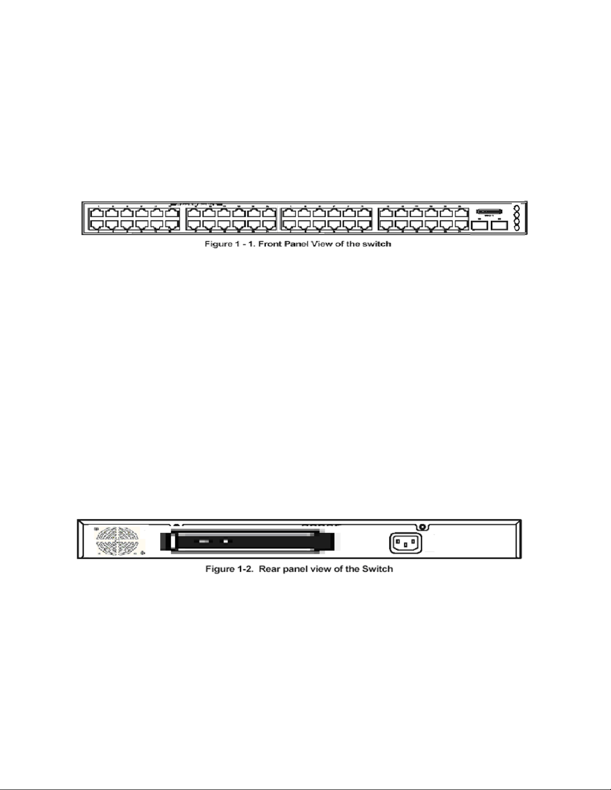
1.3 Front-Panel Components
The front panel of the switch consists of 48 1-Giga interfaces, 4 LED indicators, an RS-232
communication port, and two SFP (Mini-GBIC) Combo ports.
4 LEDs divided into two parts. 2 LED indicators on the upper display the status and power the
switch. 2 LED indicators on the lower are used to display the status of SFP interface. An
RS-232 DCE console port is for setting up and managing the switch via a connection to a
console terminal or PC using a terminal emulation program.
1.4 LED Indicators
2 LED indicators on the upper represent the status and power the switch. 2 LED indicators
on the lower are used to display each activity and link status of two SFP interfaces.
1.5 Rear Panel Description
The rear panel of the switch contains an AC power connector and a slot to plug in the 10 GE
daughter board.
The AC power connector is a standard three-pronged connector that supports the power
cord. Plug the female connector of the provided power cord into this socket, and the male
side of the cord into a power outlet. The switch automatically adjusts its power setting to any
supply voltage in the range from 100 ~ 240 VAC at 50 ~ 60 Hz.
The FortiSwitch-100 ships with one of two different daughter board types that provide the 10
GE uplink interfaces. For the FS-TRX100-CX4, the daughter board provides four powered
CX4 interfaces; For the FS-TRX100-SFP it provides four SFP+ interfaces.
25
Page 26

1.6 Management Options
The system may be managed out-of-band through the console port on the front panel or
in-band using Telnet, a Web Browser, or SNMP.
1.7 Web-based Management Interface
After you have successfully installed the switch, you can configure the switch, monitor the
LED panel, and display statistics graphically using a Web browser, such as Netscape
Navigator (version 6.2 and higher) or Microsoft® Internet Explorer (version 5.0).
NOTE: To access the switch through a Web browser, the computer running the Web
browser must have IP-based network access to the switch.
1.8 Command Line Console Interface
Through the Serial Port or Telnet
You can also connect a computer or terminal to the serial console port or use Telnet to
access the switch. The command-line-driven interface provides complete access to all
switch management features.
1.9 SNMP-Based Management
You can manage the switch with an SNMP-compatible console program. The switch
supports SNMP version 1.0, version 2.0, and version 3.0. The SNMP agent decodes the
incoming SNMP messages and responds to requests with MIB objects stored in the
database. The SNMP agent updates the MIB objects to generate statistics The switch
supports a comprehensive set of MIB extensions:
• RFC1643 Ether-like MIB
• RFC1493 Bridge
• RFC 2819 RMON
• RFC2233 Interface MIB
• RFC2571 (SNMP Frameworks)
• RFC2572 (Message Processing for SNMP)
• RFC2573 (SNMP Applications)
• RFC2576 (Coexistence between SNMPs)
• RFC2618 (Radius-Auth-Client-MIB)
• RFC2620 (Radius-Acc-Client-MIB)
• RFC 1724 (RIPv2-MIB)
26
Page 27

• RFC 1850 (OSPF-MIB)
• RFC 1850 (OSPF-TRAP-MIB)
• RFC 2787 (VRRP-MIB)
• RFC 3289 - DIFFSERV-DSCP-TC
• RFC 3289 - DIFFSERV-MIB
• QOS-DIFFSERV-EXTENSIONS-MIB
• QOS-DIFFSERV-PRIVATE-MIB
• RFC2674 802.1p
• RFC 2932 (IPMROUTE-MIB)
• Fortinet Enterprise MIB
• ROUTING-MIB
• MGMD-MIB
• RFC 2934 PIM-MIB
• DVMRP-STD-MIB
• IANA-RTPROTO-MIB
• MULTICAST-MIB
27
Page 28
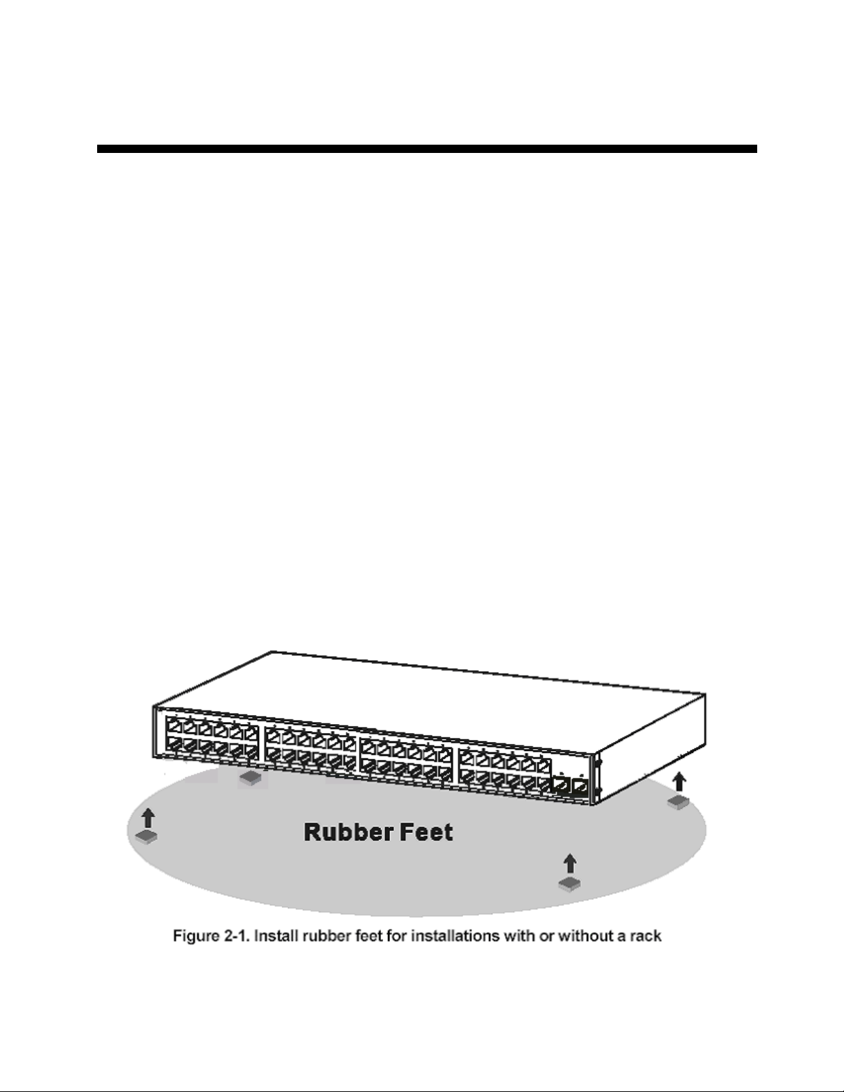
2 Installation and Quick Startup
2.1 Package Contents
Before you begin installing the switch, confirm that your package contains the following
items:
• One Fortinet FortiSwitch-100 Ethernet switch
• Mounting kit: 2 mounting brackets and screws
• Four rubber feet with adhesive backing
• One AC power cord
• This User’s Guide with Registration Card
• CLI Reference
• CD-ROM with User’s Guide and CLI Reference
2.2 Switch Installation
2.2.1 Installing the Switch Without the Rack
1. Install the switch on a level surface that can safely support the weight of the switch
and its attached cables. The switch must have adequate space for ventilation and for
accessing cable connectors.
2. Set the switch on a flat surface and check for proper ventilation. Allow at least 5 cm
(2 inches) on each side of the switch and 15 cm (6 inches) at the back for the power
cable.
3. Attach the rubber feet on the marked locations on the bottom of the chassis.
The rubber feet are recommended to keep the unit from slipping.
28
Page 29
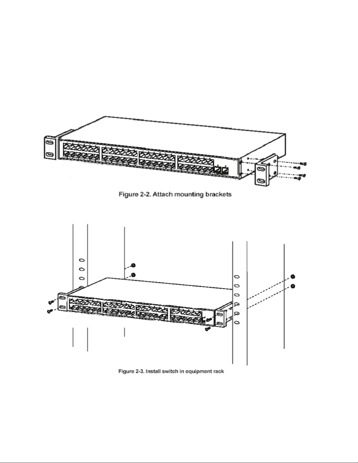
2.2.2 Installing the Switch in a Rack
You can install the switch in most standard 19-inch (48.3-cm) racks. Refer to the illustrations
below.
1. Use the supplied screws to attach a mounting bracket to each side of the switch.
2. Align the holes in the mounting bracket with the holes in the rack.
3. Insert and tighten two screws through each of the mounting brackets.
29
Page 30
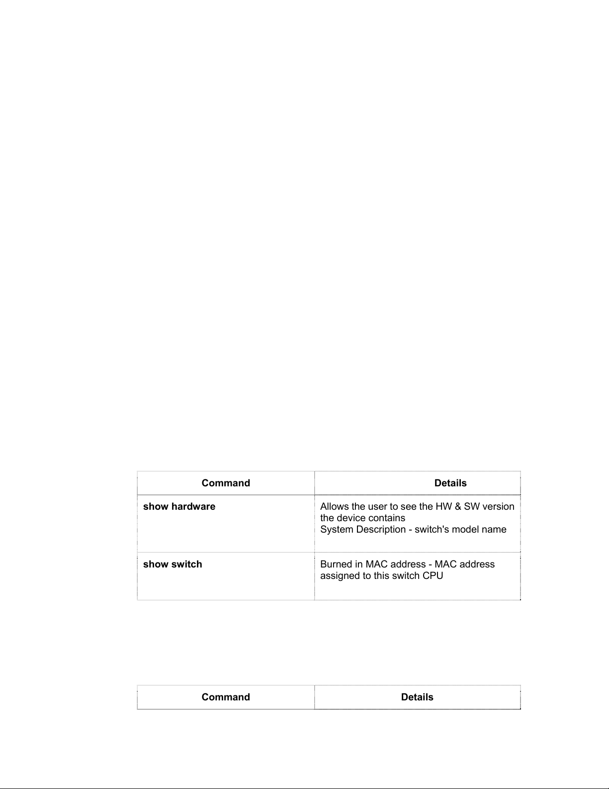
2.3 Quick Starting the Switch
1. Read the device Installation Guide for the connectivity procedure. In-band
connectivity allows access to the FortiSwitch- 100 switch locally or from a remote
workstation. The device must be configured with IP information (IP address, subnet
mask, and default gateway).
2. Turn the Power ON.
3. Allow the device to load the software until the login prompt appears. The device
initial state is called the default mode.
4. When the prompt asks for operator login, do the following:
• Type the word admin in the login area. Since a number of the Quick Setup
commands require administrator account rights, Fortinet suggests logging
into an administrator account.
• Do not enter a password because there is no password in the default mode.
• Press the <Enter> key
• The CLI Privileged EXEC mode prompt will be displayed.
• Use “configure” to switch to the Global Config mode from Privileged EXEC.
• Use “exit” to return to the previous mode.
2.4 System Information Setup
2.4.1 Quick Start up Software Version Information
Table 2-1. Quick Start up Software Version Information
Command Details
show hardware
show switch
Allows the user to see the HW & SW version
the device contains
System Description - switch's model name
Burned in MAC address - MAC address
assigned to this switch CPU
2.4.2 Quick Start up Physical Port Data
Table 2-2. Quick Start up Physical Port
Command Details
30
Page 31

show Interface status { <slot/port>
| all }
Displays the Ports
slot/port
Type - Indicates if the port is a special type of
port
Admin Mode - Selects the Port Control
Administration State
Physical Mode - Selects the desired port
speed and duplex mode
Physical Status - Indicates the port speed
and duplex mode
Link Status - Indicates whether the link is up
or down
Link Trap - Determines whether or not to
send a trap when link status changes
LACP Mode - Displays whether LACP is
enabled or disabled on this port
Flow Mode - Indicates the status of flow
control on this port
Cap. Status - Indicates the port capabilities
during auto-negotiation
2.4.3 Quick Start up User Account Management
Table 2-3. Quick Start up User Account Management
Command Details
show users
show loginsession
username <username> { passwd |
nopasswd }
Displays all users that are allowed to access
the switch
User Access Mode - Shows whether the
user is able to change parameters on the
switch (Read/Write) or is only able to view
(Read Only).
As a factory default, admin has Read/Write
access and guest has Read Only access.
There can only be one Read/Write user and
up to 5 Read Only users.
Displays all login session information
Allows the user to set passwords or change
passwords needed to login
A prompt will appear after the command is
entered requesting the old password. In the
absence of an old password leave the area
blank. The operator must press enter to
execute the command.
The system then prompts the user for a new
password then a prompt to confirm the new
password. If the new password and the
31
Page 32

confirmed password match a message will
be displayed.
The user password should not be more than
eight characters in length.
copy running-config
startup-config [ filename ]
This will save passwords and all other
changes to the device.
If you do not save the running config, all
changes will be lost when a power cycle is
performed on the switch or when the switch
is reset.
Notes
• Use of the optional [filename]
parameter sets that file name as the
system default location for the
startup config. The system will now
use that file for its startup
configuration, and future uses of
copy running-config startup-config
will copy the running config to the
same file.
• There is a maximum memory limit of
2 config files; the original system
default and one user-created file.
To create a new config file, you must
first delete any user-created config
files from memory.
• To configure the switch to boot from
a different config file, use the
command boot-system config
<filename> where filename is the
name of the config file from which
you want the system to boot (see
page 249).
2.4.4 Quick Start up IP Address
To view the network parameters the operator can access the device by the following three
methods.
• Simple Network Management Protocol - SNMP
• Telnet
• Web Browser
Table 2-4. Quick Start up IP Address
Command Details
32
Page 33

show ip interface
ip address
Displays the Network Configurations
IP Address - IP Address of the interface
Default IP is 0.0.0.0
Subnet Mask - IP Subnet Mask for the
interface
Default is 0.0.0.0
Default Gateway - The default Gateway for
this interface
Default value is 0.0.0.0
Burned in MAC Address - The Burned in
MAC Address used for inband connectivity
Network Configurations Protocol Current -
Indicates which network protocol is being
used
Default is none
Management VLAN Id - Specifies VLAN id
Web Mode - Indicates whether HTTP/Web is
enabled.
Java Mode - Indicates whether java mode is
enabled.
(Config)#interface vlan 1
(if-vlan 1)#ip address <ipaddr> <netmask>
(if-vlan 1)#exit
(Config)#ip default-gateway <gateway>
IP Address range from 0.0.0.0 to
255.255.255.255
Subnet Mask range from 0.0.0.0 to
255.255.255.255
Gateway Address range from 0.0.0.0 to
255.255.255.255
Displays all of the login session information
2.4.5 Quick Start up Uploading from Switch to
Out-of-Band PC (Only XMODEM)
Table 2-5. Quick Start up Uploading from Switch to Out-of-Band PC (XMODEM)
Command Details
copy startup-config <filename>
xmodem
This starts the upload and displays the mode
of uploading and the type of upload it is and
confirms the upload is taking place.
For example:
If the user is using HyperTerminal, the user
must specify where the file is going to be
received by the pc.
33
Page 34

2.4.6 Quick Start up Downloading from Out-of-Band PC
to Switch (Only XMODEM)
Table 2-6 Quick Start up Downloading from Out-of-Band PC to Switch
Command Details
copy xmodem startup-config
<filename>
Sets the download datatype to be an image
or config file.
The URL must be specified as: xmodem:
filepath/ filename
For example:
If the user is using HyperTerminal, the user
must specify which file is to be sent to the
switch. The switch will restart automatically
once the code has been downloaded.
2.4.7 Quick Start up Downloading from TFTP Server
Before starting a TFTP server download, the operator must complete the Quick Start up for
the IPAddress.
Table 2-7 Quick Start up Downloading from TFTP Server
Command Details
copy <url> startup-config
<filename>
Sets the download datatype to be an image
or config file.
The URL must be specified as:
tftp://ipAddr/filepath/fileName.
The startup-config option downloads the
config file using tftp and image option
downloads the code file.
2.4.8 Quick Start up Factory Defaults
Table 2-8 Quick Start up Factory Defaults
Command Details
clear config
Enter yes when the prompt pops up to clear
all the configurations made to the switch.
34
Page 35

copy running-config
startup-config [filename]
reload
Enter yes when the prompt pops up that
asks if you want to save the configurations
made to the switch.
Enter yes when the prompt pops up that
asks if you want to reset the system.
You can reset the switch or cold boot the
switch; both work effectively.
2.4.9 Connecting Devices to the Switch
After assigning IP addresses to the switch, you can connect devices to the switch.
To connect a device to an SFP transceiver port:
1. Use your cabling requirements to select an appropriate SFP transceiver type.
2. Insert the SFP transceiver (sold separately) into the SFP transceiver slot.
3. Use the appropriate network cabling to connect a device to the connectors on the SFP
transceiver.
2.4.10 Updating the Image Code on the Switch
When the switch is booted up and operational, you can update the image code by following
the steps below. If the image download fails, consult the troubleshooting steps at the end of
this section.
Note: Images are loaded onto the switch from your local TFTP server, so start by
downloading the appropriate image file from the Fortinet support portal to your local TFTP
server, then follow the steps below.
1. Ensure that there is room on the switch for the updated image file:
First, check the current image and configuration files on the switch by typing the command
dir:
(FortiSwitch-100_238) #dir
date file name file type startup size (byte)
---------- -------------------------------- -------------- ------- ---------- 2007/05/14 b4b-b-0.2.0514.biz Boot-Rom image Y 127648
2007/11/20 default.cfg Config File N 28701
2008/04/03 lb4w-r-1.04.0403.img Operation Code Y 8034434
2008/02/21 lb4w-r-1.04.0221.img Operation Code N 8034610
2008/05/20 test.2 Config File Y 29154
35
Page 36

---------- -------------------------------- -------------- ------- -----------
Total: 5 files.
Note whether there is one file with the file type “Operation Code” or two (as in the example
above). If there are two “Operation Code” files, you must first delete the oldest image file
using the following command sequence (inserting the file name of the oldest operation code
file in place of the example below):
(FortiSwitch-100_238) #delete lb4w-r-1.04.0221.img
Are you sure you want to delete? (y/n) y
Image File "lb4w-r-1.04.0221.img" Deleted!
(FortiSwitch-100_238) #dir
date file name file type startup size (byte)
---------- -------------------------------- -------------- ------- ---------- 2007/05/14 b4b-b-0.2.0514.biz Boot-Rom image Y 127648
2007/11/20 default.cfg Config File N 28701
2008/04/03 lb4w-r-1.04.0403.img Operation Code Y 8034434
2008/05/20 test.2 Config File Y 29154
---------- -------------------------------- -------------- ------- -----------
2. Configure an IP address on "interface vlan 1" (if not already configured):
The FortiSwitch-100 must have an IP address in order to communicate with the TFTP server.
If one has already been successfully configured on the switch, skip to step 3.
You can give the switch a static IP address manually, or configure a DHCP server to provide
an IP address dynamically.
To configure a dynamic IP address using DHCP:
Type the commands shown below to configure the FortiSwitch to acquire an IP address from
your DHCP server:
(FortiSwitch-100_238) #config
(FortiSwitch-100_238) (Config)#interface vlan 1
(FortiSwitch-100_238) (if-vlan 1)#ip address protocol dhcp
Changing protocol mode will reset ip configuration.
Are you sure you want to continue? (y/n)y
(FortiSwitch-100_238) (if-vlan 1)#exit
(FortiSwitch-100_238) (Config)#exit
To manually configure a static IP address:
If you are not using DHCP to automatically assign an IP address to the FortiSwitch, follow the
steps below to configure a static IP address on the switch, substituting the appropriate IP
address for the example shown. If you do not know what IP address to assign to the switch,
contact your IT department.
(FortiSwitch-100_238) #config
(FortiSwitch-100_238) (Config)#interface vlan 1
(FortiSwitch-100_238) (if-vlan 1)#ip address protocol none
Changing protocol mode will reset ip configuration.
Are you sure you want to continue? (y/n)y
(FortiSwitch-100_238) (if-vlan 1)#ip address 172.18.21.210 255.255.252.0
36
Page 37

Note: When configuring a static IP address, you must also configure a default gateway.
Use the following commands, substituting the appropriate default gateway address for the
example:
(FortiSwitch-100_238) (if-vlan 1)#exit
(FortiSwitch-100_238) (Config)#ip default-gateway 172.18.20.1
(FortiSwitch-100_238) (Config)#ex
(FortiSwitch-100_238) #show ip interface
IP Address..................................... 172.18.21.210
Subnet Mask.................................... 255.255.252.0
Default Gateway................................ 172.18.20.1
Burned In MAC Address.......................... 00:1B:24:1D:DD:39
Network Configuration Protocol Current......... None
DHCP Client Identifier TEXT.................... Default
Management VLAN ID............................. 1
Web Mode....................................... Enable
Web Port....................................... 80
Java Mode...................................... Enable
3. Use the "TFTP" function to upgrade the code:
Once an IP address has been configured on the FortiSwitch, use the copy command on the
FortiSwitch to copy the image file via TFTP. Type the command below, substituting the
appropriate IP address and file path for those shown in the example.
Note:
• The IP address is the address of the local TFTP server from which you’re
downloading the image file.
• When you type the file path, do not include the root!
(FortiSwitch-100_238) #copy tftp://10.10.10.30/Releases/TrxOS/1.08/lb4w-r-1.08.0819.img image
lb4w-r-1.08.0819.img
Mode........................................... TFTP
Set TFTP Server IP............................. 10.10.10.30
TFTP Path......................................
TFTP Filename.................................. lb4w-r-1.08.0819.img
Data Type...................................... Code
Management access will be blocked for the duration of the transfer
Are you sure you want to start? (y/n) y
TFTP code transfer starting
Verifying CRC of file in Flash File System
TFTP receive complete... storing in Flash File System...
File transfer operation completed successfully.
4. Next, display all of the files (including the new run time code) using the "dir"
command:
(FortiSwitch-100_238) #dir
date file name file type startup size (byte)
37
Page 38

---------- -------------------------------- -------------- ------- ---------- 2007/05/14 b4b-b-0.2.0514.biz Boot-Rom image Y 127648
2007/11/20 default.cfg Config File N 28701
2008/04/03 lb4w-r-1.04.0403.img Operation Code Y 8034434
2008/08/19 lb4w-r-1.08.0819.img Operation Code N 8039249
2008/05/20 test.2 Config File Y 29154
---------- -------------------------------- -------------- ------- -----------
Total: 5 files.
5. Set boot up code using the following command:
(FortiSwitch-100_238) #boot-system opcode lb4w-r-1.08.0819.img
Start Up Success!
6. Display all of the files again (start up code should be set to the new runtime code):
(FortiSwitch-100_238) #dir
date file name file type startup size (byte)
---------- -------------------------------- -------------- ------- ---------- 2007/05/14 b4b-b-0.2.0514.biz Boot-Rom image Y 127648
2007/11/20 default.cfg Config File N 28701
2008/04/03 lb4w-r-1.04.0403.img Operation Code N 8034434
2008/08/19 lb4w-r-1.08.0819.img Operation Code Y 8039249
2008/05/20 test.2 Config File Y 29154
---------- -------------------------------- -------------- ------- -----------
Total: 5 files.
Now you are finished with the upgrade procedure! Please reload the switch and configure
as desired.
Troubleshooting the Download Procedure
If you have configured an IP address (statically or via DHCP) on the FortiSwitch and still
cannot download the image file, try the following:
• Verify that the FortiSwitch is able to access the TFTP server by using the ping
command. Substitute the IP address of your TFTP server for the one shown in the
example below:
(FortiSwitch-100_238) #ping 10.10.10.31
PING to 10.10.10.31, by 5 32-byte payload ICMP packets, timeout is 3 seconds:
Reply from 10.10.10.31: bytes=32 time=0ms
Reply from 10.10.10.31: bytes=32 time=0ms
Reply from 10.10.10.31: bytes=32 time=0ms
Reply from 10.10.10.31: bytes=32 time=0ms
Reply from 10.10.10.31: bytes=32 time=0ms
Ping statistics for 10.10.10.31 :
5 packets transmitted, 5 packets received (100%), 0 packets lost (0%)
proximate round trip times:
Minimum = 0 ms, Maximum = 0 ms, Average = 0 ms
38
Page 39

• If there is no response from the TFTP server, verify the IP settings by typing show ip
interface to ensure that the IP address and default gateway have been entered
correctly.
• If the settings are correct but there is still no response from the TFTP server, ensure
that the TFTP server is connected to a network which the FortiSwitch can access.
The network connection must be made through one of the front ports of the
FortiSwitch switch which belongs to VLAN 1.
wit to be an active part of a manageable network. These components include a CPU,
memory for data storage, other related hardware, and SNMP agent firmware. Activities on
the switch can be monitored with these components, while the switch can be manipulated to
carry out specific tasks.
2.5 Set Up your Switch Using Console
Access
Out-of-band management requires connecting a terminal, such as a VT-100 or a PC running
a terminal-emulation program (such as HyperTerminal, which is automatically installed with
Microsoft Windows) to the RS-232 DCE console port of the switch. Switch management
using the RS-232 DCE console port is called Local Console Management to differentiate it
from management done via management platforms, such as DView or HP OpenView.
Make sure the terminal or PC you are using to make this connection is configured to match
these settings. If you are having problems making this connection on a PC, make sure the
emulation is set to VT-100 or ANSI. If you still don’t see anything, try pressing <Ctrl> + r to
refresh the screen.
First-time configuration must be carried out through a console, that is, either (a) a
VT100-type serial data terminal, or (b) a computer running communications software set to
emulate a VT100. The console must be connected to the Diagnostics port. This is an RS-232
port with a 9-socket D-shell connector and DCE-type wiring. Make the connection as follows:
1. Obtain suitable cabling for the connection.
You can use a null-modem RS-232 cable or an ordinary RS-232 cable and a null-modem adapter. One
end of the cable (or cable/adapter combination) must have a 9-pin D-shell connector suitable for the
Diagnostics port; the other end must have a connector suitable for the console’s serial communications
port.
2. Power down the devices, attach the cable (or cable/adapter combination) to the correct ports, and
restore power.
3. Set the console to use the following communication parameters for your terminal:
. The console port is set for the following configuration:
. Baud rate: 115200
. Data width: 8 bits
. Parity: none
. Stop bits: 1
. Flow Control none
A typical console connection is illustrated below:
39
Page 40

Figure 3-1: Console Setting Environment
2.6 Set Up your Switch Using Telnet Access
Once you have set an IP address for your switch, you can use a Telnet program (in a VT-100
compatible terminal mode) to access and control the switch. Most of the screens are identical,
whether accessed from the console port or from a Telnet interface.
40
Page 41

3 Web-Based Management Interface
3.1 Overview
The Fortinet FortiSwitch-100 Managed Switch provides a built-in browser interface that
lets you configure and manage it remotely using a standard Web browser such as Microsoft
Internet Explorer 5.0 or later or Netscape Navigator 6.0 or later. This interface also allows for
system monitoring and management of the switch. The ‘help’ page covers many of the basic
functions and features of the switch and its Web interface. When you configure the switch for
the first time from the console, you can assign an IP address and subnet mask to the switch.
Thereafter, you can access the switch’s Web interface directly using your Web browser by
entering the switch’s IP address into the address bar. In this way, you can use your Web
browser to manage the switch from a central location, just as if you were directly connected
to the switch’s console port. Figure 4-1 shows this management method.
Figure 4-1: Web Management Method
3.2 How to log in
The Fortinet FortiSwitch-100 Managed Switch can be configured remotely from Microsoft
Internet Explorer (version 5.0 or above), or Netscape Navigator (version 4.78 or above).
1. Determine the IP address of your managed switch.
2. Open your Web browser.
3. Log in to the managed switch using whatever IP address the unit is currently configured
with.
Use the default user name of admin and default of no password, or whatever LAN address
and password you have set up.
A login window opens:
Click the Login link.
A user name and password dialog box opens.
41
Page 42

4. Type the default user name of admin and default of no password, or whatever password
you have set up.
Once you have entered your access point name, your Web browser automatically finds the
FortiSwitch-100 Managed Switch and display the home page, as shown below.
3.3 Web-Based Management Menu
Figure 4-3: System Information page
This above page displays system information, such as:
• System Description
• System Name
• System Location
• System Contact
• IP Address
• System Object ID (OID)
• System Up Time
Menus
The Web-based interface enables navigation through several menus. The main navigation
menu is on the left of every page and contains the screens that let you access all the
commands and statistics the switch provides.
Main Menus
• System
• Switching
42
Page 43

• Routing
• Security
• QoS
• IP Multicast
Figure 4-4: Main Menus
Secondary Menus
The Secondary Menus under the Main Menu contain a host of options that you can use
to configure your switch. The online help contains a detailed description of the features on
each screen. You can click the ‘help’ or the question mark at the top right of each screen to
view the help menu topics.
The Secondary Menus are detailed below, with cross-references to the sections in this
manual that contain the corresponding command descriptions.
System
• ARP Cache — see “show arp”
• Inventory — see “show hardware”
• Configuration — see “Management Commands and Device Configuration Commands”
• Forwarding Database — see “Device Configuration Commands’ L2MAC Address”
• Logs — see “System Information and Statistics Commands”
• Port — see “Device Configuration Commands’ Interface”
• SNMP — see “SNMP Server Commands and SNMP Trap Commands”
• Statistics — see “show interface counters”
• System Utilities — see “System Utilities”
• Trap Manager — see “show traplog and SNMP Trap Commands”
• SNTP — see “SNTP Commands”
• DHCP Client — see “DHCP Client Commands”
Switching
• VLAN — see “VLAN Management Commands”
• Protocol-based VLAN — see “VLAN Management Commands”
• GARP — see “GVRP and Bridge Extension Commands”
• IGMP Snooping — see “IGMP Snooping Commands”
• Port Channel — see “Port Channel Commands”
• Multicast Forwarding DataBase — see “L2 MAC Address and Multicast Forwarding
Database Tables Commands”
43
Page 44

• Spanning Tree — see “Spanning Tree Commands”
• Class of Service — see “L2 Priority Commands”
• Port Security — see “Port Security Configuration Commands”
Routing
• ARP — see “Address Resolution Protocol (ARP) Commands”
• IP — see “IP Routing Commands”
• OSPF — see “Open Shortest Path First (OSPF) Commands”
• BOOTP/DHCP Relay Agent — see “BOOTP/DHCP Relay Commands”
• DNS Relay — see “Domain Name Server Relay Commands”
• RIP — see “Routing Information Protocol (RIP) Commands”
• Router Discovery — see “Router Discovery Protocol Commands”
• Router — see “IP Routing Commands”
• VLAN Routing — see “VLAN Routing Commands”
• VRRP — see “Virtual Router Redundancy Protocol (VRRP) Commands”
Security
• Port Access Control — see “Dot1x Configuration Commands”
• RADIUS — see “Radius Configuration Commands”
• TACACS — see “TACACS Configuration Commands”
• IP Filter — see “Network Commands”
• Secure HTTP — see “HTTP Commands”
• Secure Shell — see “Secure Shell (SSH) Commands”
QoS
• ACL — see “ACL Commands”
• Diffserv — see “Differentiated Services Commands”
• Class of Service see "Class of Service Commands"
IP Multicast
• DVMRP — see “DVMRP Commands”
• IGMP — see “IGMP Commands”
• Multicast — see “Multicast Commands”
• MDebug — see “Multicast Commands”
• PIM-DM — see “PIM-DM Commands”
• PIM-SM — see “PIM-SM Commands”
System-Wide Popup Menus
The FortiSwitch-100 Managed Switch also provides several popup menus.
44
Page 45

Figure 4-5: System-wide menus
You can also access the main navigation menu by right clicking on the image of the switch
and browsing to the menu you want to use.
Port-Specific Popup Menus
The FortiSwitch-100 Managed Switch also provides several popup menus for each port.
You can access a port-specific popup menu by right clicking on the desired port in the
image of the switch and browsing to the menu you want to use.
45
Page 46

4 Command Line Interface Structure
and Mode-based CLI
The Command Line Interface (CLI) syntax, conventions, and terminology are described in
this section. Each CLI command is illustrated using the structure outlined below.
4.1 CLI Command Format
Commands are followed by values, parameters, or both.
Example 1
IP address <ipaddr> <netmask> [<gateway>]
• Ip address is the command name.
• <ipaddr> <netmask> are the required values for the command.
• [<gateway>] is the optional value for the command.
Example 2
snmp-server host <loc>
• snmp-server location is the command name.
• <loc> is the required parameter for the command.
Example 3
clear vlan
• clear vlan is the command name.
Command
The text in bold, non-italic font must be typed exactly as shown.
4.2 CLI Mode-based Topology
Parameters
Parameters are order dependent.
The text in bold italics should be replaced with a name or number. To use spaces as part of a
name parameter, enclose it in double quotes like this: "System Name with Spaces".
Parameters may be mandatory values, optional values, choices, or a combination.
– <parameter>. The <> angle brackets indicate that a mandatory parameter must be entered
in place of the brackets and text inside them.
– [parameter]. The [] square brackets indicate that an optional parameter may be entered in
place of the brackets and text inside them.
– choice1 | choice2. The | indicates that only one of the parameters should be entered.
46
Page 47

The {} curly braces indicate that a parameter must be chosen from the list of choices.
Values
ipaddr This parameter is a valid IP address, made up of four decimal bytes ranging from
0 to 255. The default for all IP parameters consists of zeros (that is, 0.0.0.0). The interface IP
address of 0.0.0.0 is invalid.
macaddr The MAC address format is six hexadecimal numbers separated by colons, for
example 00:06:29:32:81:40.
areaid Area IDs may be entered in dotted-decimal notation (for example, 0.0.0.1). An area
ID of 0.0.0.0 is reserved for the backbone. Area IDs have the same form as IP addresses, but
are distinct from IP addresses. The IP network number of the sub-netted network may be
used for the area ID.
routerid The value of <router id> must be entered in 4-digit dotted-decimal notation (for
example, 0.0.0.1). A router ID of 0.0.0.0 is invalid.
slot/port This parameter denotes a valid slot number and a valid port number. For example,
0/1 represents slot number 0 and port number 1. The <slot/port> field is composed of a valid
slot number and a valid port number separated by a forward slash (/).
logical slot/port This parameter denotes a logical slot number and logical port number
assigned. This is applicable in the case of a port-channel (LAG). The operator can use the
logical slot number and the logical port number to configure the port-channel.
Conventions
Network addresses are used to define a link to a remote host, workstation, or network.
Network addresses are shown using the following syntax:
Table 5-1. Network Address Syntax
Address
Format
Range
Type
IPAddr
A.B.C.D
MacAddr
YY:YY:YY:Y
Y:YY:YY
0.0.0.0 to
255.255.2
55.255
hexideci
mal digit
pairs
Double quotation marks such as "System Name with Spaces" set off user defined strings. If
the operator wishes to use spaces as part of a name parameter then it must be enclosed in
double quotation marks.
47
Page 48

Empty strings (““) are not valid user defined strings. Command completion finishes spelling
the command when enough letters of a command are typed to uniquely identify the
command word. The command may be executed by typing <enter> (command abbreviation)
or the command word may be completed by typing the <tab> or <space bar> (command
completion).
The value 'Err' designates that the requested value was not internally accessible. This should
never happen and indicates that there is a case in the software that is not handled correctly.
The value of '-----' designates that the value is unknown.
Annotations
The CLI allows the user to type single-line annotations at the command prompt for use when
writing test or configuration scripts and for better readability. The exclamation point (‘!’)
character flags the beginning of a comment. The comment flag character can begin a word
anywhere on the command line and all input following this character is ignored. Any
command line that begins with the character ‘!’ is recognized as a comment line and ignored
by the parser.
Some examples are provided below:
! Script file for displaying the ip interface
! Display information about interfaces
show ip interface 1/0/1 !Displays the information about the first interface
! Display information about the next interface
show ip interface 1/0/2
! End of the script file
48
Page 49

5 Switching Commands
5.1 System Information and Statistics
commands
5.1.1 show arp
This command displays connectivity between the switch and other devices. The Address
Resolution Protocol (ARP) cache identifies the MAC addresses of the IP stations
communicating with the switch.
Syntax
show arp
Default Setting
None
Command Mode
Privileged Exec
Display Message
MAC Address: A unicast MAC address for which the switch has forwarding and/or filtering information. The
format is 6 two-digit hexadecimal numbers that are separated by colons. For example: 00:23:45:67:89:AB
IP Address: The IP address assigned to each interface.
Interface: A valid slot number and a valid port number.
5.1.2 show calendar
This command displays the system clock.
Syntax
49
Page 50

show calendar
Default Setting
None
Command Mode
Privileged Exec
Display Message
Current Time displays system time
5.1.3 show eventlog
This command displays the event log, which contains error messages from the system. The
event log is not cleared on a system reset.
Syntax
show eventlog [unit]
unit - The unit number of the remote system. The range is 1 to 1.
Default Setting
None
Command Mode
Privileged Exec
Display Message
File: The file in which the event originated.
Line: The line number of the event.
Task Id: The task ID of the event.
Code: The event code.
Time: The time this event occurred.
Note: Event log information is retained across a switch reset.
50
Page 51

5.1.4 show running-config
This command is used to display/capture the current setting of different protocol packages
supported on switch. This command displays/captures only commands with
settings/configurations with values that differ from the default value. The output is displayed
in script format, which can be used to configure another switch with the same configuration.
When a script name is provided, the output is redirected to a configuration script. The option
[all] will also enable the display/capture of all commands with settings/configurations that
include values that are same as the default values. If the optional <scriptname> is provided
with a file name extension of “.scr”, the output will be redirected to a script file.
Syntax
show running-config [all] [<scriptname>]
[all] - enable the display/capture of all commands with settings/configurations that include values that
are same as the default values.
<scriptname> - redirect the output to the file <scriptname>.
Default Setting
None
Command Mode
Privileged Exec
5.1.5 show sysinfo
This command displays switch brief information and MIBs supported.
None
Syntax
show sysinfo
Default Setting
Command Mode
51
Page 52

Privileged Exec
Display Message
System Description: The text used to identify this switch.
System Name: The name used to identify the switch.
System Location: The text used to identify the location of the switch. May be up to 31 alpha-numeric
characters. The factory default is blank.
System Contact: The text used to identify a contact person for this switch. May be up to 31 alphanumeric
characters. The factory default is blank.
System Object ID: The manufacturing ID.
System Up Time: The time in days, hours and minutes since the last switch reboot.
MIBs Supported: A list of MIBs supported by this agent.
5.1.6 show hardware
This command displays inventory information for the switch.
Syntax
show hardware
Default Setting
None
Command Mode
Privileged Exec
Display Message
System Description: Text used to identify the product name of this switch.
Machine Type: Specifies the machine type as defined by the Vital Product Data.
Machine Model: Specifies the machine model as defined by the Vital Product Data.
Serial Number: The unique box serial number for this switch.
Label Revision Number: The label revision serial number of this switch is used for manufacturing
purposes.
Part Number: Manufacturing part number.
Hardware Version: The hardware version of this switch. It is divided into four parts. The first byte is the
major version and the second byte represents the minor version.
Loader Version: The release version maintenance number of the loader code currently running on the
switch. For example, if the release was 1, the version was 2, and the maintenance number was 4, the
format would be '1.2.4'.
Boot Rom Version: The release version maintenance number of the boot ROM code currently running on
the switch. For example, if the release was 1, the version was 2, and the maintenance number was 4, the
format would be '1.2.4'.
Operating Code Version: The release version maintenance number of the code currently running on the
switch. For example, if the release was 1, the version was 2, and the maintenance number was 4, the
format would be '1.2.4'.
52
Page 53

5.1.7 show loginsession
This command displays current telnet and serial port connections to the switch.
Syntax
show loginsession
Default Setting
None
Command Mode
Privileged Exec
Display Message
ID: Login Session ID
User Name: The name the user will use to login using the serial port or Telnet. A new user may be added
to the switch by entering a name in a blank entry. The user name may be up to 8 characters, and is not case
sensitive. Two users are included as the factory default, admin, and guest.
Connection From: IP address of the telnet client machine or EIA-232 for the serial port connection.
Idle Time: Time this session has been idle.
Session Time: Total time this session has been connected.
Session Type: Shows the type of session: telnet, serial or SSH.
5.2 Device Configuration Commands
5.2.1 Interface
5.2.1.1 show interface status
This command displays the Port monitoring information for the system.
Syntax
show interface status {<slot/port> | all}
53
Page 54

<slot/port> - is the desired interface number.
all - This parameter displays information for all interfaces.
Default Setting
None
Command Mode
Privileged Exec
Display Message
Intf: The physical slot and physical port.
Type: If not blank, this field indicates that this port is a special type of port. The possible values are:
Source - This port is a monitoring port.
PC Mbr - This port is a member of a port-channel (LAG).
Dest - This port is a probe port.
Admin Mode: Selects the Port control administration state. The port must be enabled in order for it to be
allowed into the network. – It may be enabled or disabled. The factory default is enabled.
Physical Mode: Selects the desired port speed and duplex mode. If auto-negotiation support is selected,
then the duplex mode and speed will be set from the auto-negotiation process. Note that the port's
maximum capability (full duplex -100M) will be advertised. Otherwise, this object will determine the port's
duplex mode and transmission rate. The factory default is Auto.
Physical Status: Indicates the port speed and duplex mode.
Link Status: Indicates whether the Link is up or down.
Link Trap: This object determines whether to send a trap when link status changes. The factory default is
enabled.
LACP Mode: Displays whether LACP is enabled or disabled on this port.
Flow Mode: Displays flow control mode.
Capabilities Status: Displays interface capabilities.
5.2.1.2 show interface counters
This command displays a summary of statistics for a specific interface or all interfaces.
Syntax
show interface counters {<slot/port> | all}
<slot/port> - is the desired interface number.
all - This command displays statistics information for all interfaces.
Default Setting
None
Command Mode
54
Page 55

Privileged Exec
Display Message
The display parameters when the argument is '<slot/port>' are as follows:
Packets Received Without Error: The total number of packets (including broadcast packets and
multicast packets) received by the processor.
Packets Received With Error: The number of inbound packets that contained errors preventing them
from being deliverable to a higher-layer protocol.
Broadcast Packets Received: The total number of packets received that were directed to the broadcast
address. Note that this does not include multicast packets.
Packets Transmitted Without Error: The total number of packets transmitted out of the interface.
Transmit Packets Errors: The number of outbound packets that could not be transmitted because of
errors.
Collisions Frames: The best estimate of the total number of collisions on this Ethernet segment.
Time Since Counters Last Cleared: The elapsed time, in days, hours, minutes, and seconds since the
statistics for this port were last cleared.
The display parameters when the argument is 'all' are as follows:
Interface: The physical slot and physical port or the logical slot and logical port.
Summary: The summation of the statistics of all ports.
Packets Received Without Error: The total number of packets (including broadcast packets and
multicast packets) received.
Packets Received With Error: The number of inbound packets that contained errors preventing them
from being deliverable to a higher-layer protocol.
Broadcast Packets Received: The total number of packets received that were directed to the broadcast
address. Note that this does not include multicast packets.
Packets Transmitted Without Error: The total number of packets transmitted.
Transmit Packets Errors: The number of outbound packets that could not be transmitted because of
errors.
Collisions Frames: The best estimate of the total number of collisions on this Ethernet segment.
This command displays detailed statistics for a specific port or for all CPU traffic based upon
the argument.
Syntax
show interface counters detailed {<slot/port> | switchport}
<slot/port> - is the desired interface number.
switchport - This parameter specifies whole switch or all interfaces.
Default Setting
None
55
Page 56

Command Mode
Privileged Exec
Display Message
The display parameters when the argument is ' <slot/port>' are as follows:
Total Packets Received (Octets): The total number of octets of data (including those in bad packets)
received on the network (excluding framing bits but including FCS octets). This object can be used as a
reasonable estimate of Ethernet utilization. If greater precision is desired, the etherStatsPkts and
etherStatsOctets objects should be sampled before and after a common interval. The result of this
equation is the value Utilization which is the percent utilization of the Ethernet segment on a scale of 0 to
100 percent.
Packets Received 64 Octets: The total number of packets (including bad packets) received that were
64 octets in length (excluding framing bits but including FCS octets).
Packets Received 65-127 Octets: The total number of packets (including bad packets) received that
were between 65 and 127 octets in length inclusive (excluding framing bits but including FCS octets).
Packets Received 128-255 Octets: The total number of packets (including bad packets) received that
were between 128 and 255 octets in length inclusive (excluding framing bits but including FCS octets).
Packets Received 256-511 Octets: The total number of packets (including bad packets) received that
were between 256 and 511 octets in length inclusive (excluding framing bits but including FCS octets).
Packets Received 512-1023 Octets: The total number of packets (including bad packets) received that
were between 512 and 1023 octets in length inclusive (excluding framing bits but including FCS octets).
Packets Received 1024-1518 Octets: The total number of packets (including bad packets) received
that were between 1024 and 1518 octets in length inclusive (excluding framing bits but including FCS
octets).
Packets Received > 1522 Octets: The total number of packets received that were longer than 1522
octets (excluding framing bits, but including FCS octets) and were otherwise well formed.
Packets RX and TX 64 Octets: The total number of packets (including bad packets) received that were
64 octets in length (excluding framing bits but including FCS octets).
Packets RX and TX 65-127 Octets: The total number of packets (including bad packets) received that
were between 65 and 127 octets in length inclusive (excluding framing bits but including FCS octets).
Packets RX and TX 128-255 Octets: The total number of packets (including bad packets) received that
were between 128 and 255 octets in length inclusive (excluding framing bits but including FCS octets).
Packets RX and TX 256-511 Octets: The total number of packets (including bad packets) received that
were between 256 and 511 octets in length inclusive (excluding framing bits but including FCS octets).
Packets RX and TX 512-1023 Octets: The total number of packets (including bad packets) received
that were between 512 and 1023 octets in length inclusive (excluding framing bits but including FCS
octets).
Packets RX and TX 1024-1518 Octets: The total number of packets (including bad packets) received
that were between 1024 and 1518 octets in length inclusive (excluding framing bits but including FCS
octets).
Packets RX and TX 1519-1522 Octets: The total number of packets (including bad packets) received
that were between 1519 and 1522 octets in length inclusive (excluding framing bits but including FCS
octets).
Packets RX and TX 1523-2047 Octets: The total number of packets (including bad packets) received
that were between 1523 and 2047 octets in length inclusive (excluding framing bits but including FCS
octets).
Packets RX and TX 2048-4095 Octets: The total number of packets (including bad packets) received
that were between 2048 and 4095 octets in length inclusive (excluding framing bits but including FCS
octets).
Packets RX and TX 4096-9216 Octets: The total number of packets (including bad packets) received
that were between 4096 and 9216 octets in length inclusive (excluding framing bits but including FCS
octets).
56
Page 57

Total Packets Received Without Errors
Unicast Packets Received: The number of subnetwork-unicast packets delivered to a higher-layer
protocol.
Multicast Packets Received: The total number of good packets received that were directed to a
multicast address. Note that this number does not include packets directed to the broadcast address.
Broadcast Packets Received: The total number of good packets received that were directed to the
broadcast address. Note that this does not include multicast packets.
Total Packets Received with MAC Errors
Jabbers Received: The total number of packets received that were longer than 1518 octets (excluding
framing bits, but including FCS octets), and had either a bad FCS with an integral number of octets (FCS
Error) or a bad FCS with a non-integral number of octets (Alignment Error). Note that this definition of
jabber is different than the definition in IEEE-802.3 section 8.2.1.5 (10BASE5) and section 10.3.1.4
(10BASE2). These documents define jabber as the condition where any packet exceeds 20 ms. The
allowed range to detect jabber is between 20 ms and 150 ms.
Undersize Received: The total number of packets received that were less than 64 octets in length with
GOOD CRC(excluding framing bits but including FCS octets).
Fragments Received: The total number of packets received that were less than 64 octets in length with
ERROR CRC(excluding framing bits but including FCS octets).
Alignment Errors: The total number of packets received that had a length (excluding framing bits, but
including FCS octets) of between 64 and 1518 octets, inclusive, but had a bad FCS with a non-integral
number of octets.
FCS Errors: The total number of packets received that had a length (excluding framing bits, but
including FCS octets) of between 64 and 1518 octets, inclusive, but had a bad FCS with an integral
number of octets
Overruns: The total number of frames discarded as this port was overloaded with incoming packets, and
could not keep up with the inflow.
Total Packets Transmitted (Octets)
Packets Transmitted 64 Octets: The total number of packets (including bad packets) received that
were 64 octets in length (excluding framing bits but including FCS octets).
Packets Transmitted 65-127 Octets: The total number of packets (including bad packets) received that
were between 65 and 127 octets in length inclusive (excluding framing bits but including FCS octets).
Packets Transmitted 128-255 Octets: The total number of packets (including bad packets) received
that were between 128 and 255 octets in length inclusive (excluding framing bits but including FCS
octets).
Packets Transmitted 256-511 Octets: The total number of packets (including bad packets) received
that were between 256 and 511 octets in length inclusive (excluding framing bits but including FCS
octets).
Packets Transmitted 512-1023 Octets: The total number of packets (including bad packets) received
that were between 512 and 1023 octets in length inclusive (excluding framing bits but including FCS
octets).
Packets Transmitted 1024-1518 Octets: The total number of packets (including bad packets) received
that were between 1024 and 1518 octets in length inclusive (excluding framing bits but including FCS
octets).
Packets Transmitted 1519-1522 Octets: The total number of packets (including bad packets) received
that were between 1519 and 1522 octets in length inclusive (excluding framing bits but including FCS
octets).
Max Info: The maximum size of the Info (non-MAC) field that this port will receive or transmit.
Total Packets Transmitted Successfully
Unicast Packets Transmitted: The total number of packets that higher-level protocols requested be
transmitted to a subnetwork-unicast address, including those that were discarded or not sent.
Multicast Packets Transmitted: The total number of packets that higher-level protocols requested be
transmitted to a Multicast address, including those that were discarded or not sent.
57
Page 58

Broadcast Packets Transmitted: The total number of packets that higher-level protocols requested be
transmitted to the Broadcast address, including those that were discarded or not sent.
Total Transmit Errors
FCS Errors: The total number of packets transmitted that had a length (excluding framing bits, but
including FCS octets) of between 64 and 1518 octets, inclusive, but had a bad FCS with an integral
number of octets
Tx Oversized: The total number of frames that exceeded the max permitted frame size. This counter
has a max increment rate of 815 counts per sec. at 10 Mb/s.
Underrun Errors: The total number of frames discarded because the transmit FIFO buffer became
empty during frame transmission.
Total Transmited Packets Discards
Single Collision Frames: A count of the number of successfully transmitted frames on a particular
interface for which transmission is inhibited by exactly one collision.
Multiple Collision Frames: A count of the number of successfully transmitted frames on a particular
interface for which transmission is inhibited by more than one collision.
Excessive Collisions: A count of frames for which transmission on a particular interface fails due to
excessive collisions.
GVRP PDUs Received: The count of GVRP PDUs received in the GARP layer.
GVRP PDUs Transmitted: The count of GVRP PDUs transmitted from the GARP layer.
GVRP Failed and Registrations: The number of times attempted GVRP registrations could not be
completed.
GMRP PDUs received: The count of GMRP PDUs received in the GARP layer.
GMRP PDUs Transmitted: The count of GMRP PDUs transmitted from the GARP layer.
GMRP Failed Registrations: The number of times attempted GMRP registrations could not be completed.
STP BPDUs Transmitted: Spanning Tree Protocol Bridge Protocol Data Units sent.
STP BPDUs Received: Spanning Tree Protocol Bridge Protocol Data Units received.
RSTP BPDUs Transmitted: Rapid Spanning Tree Protocol Bridge Protocol Data Units sent.
RSTP BPDUs Received: Rapid Spanning Tree Protocol Bridge Protocol Data Units received.
MSTP BPDUs Transmitted: Multiple Spanning Tree Protocol Bridge Protocol Data Units sent.
MSTP BPDUs Received: Multiple Spanning Tree Protocol Bridge Protocol Data Units received.
EAPOL Frames Received: The number of valid EAPOL frames of any type that have been received by this
authenticator.
EAPOL Frames Transmitted: The number of EAPOL frames of any type that have been transmitted by
this authenticator.
Time Since Counters Last Cleared: The elapsed time, in days, hours, minutes, and seconds since the
statistics for this port were last cleared.
The display parameters when the argument is ‘switchport’ are as follows:
Total Packets Received (Octets): The total number of octets of data received by the processor (excluding
framing bits but including FCS octets).
Packets Received Without Error: The total number of packets (including broadcast packets and
multicast packets) received by the processor.
Unicast Packets Received: The number of subnetwork-unicast packets delivered to a higher-layer
protocol.
Multicast Packets Received: The total number of packets received that were directed to a multicast
address. Note that this number does not include packets directed to the broadcast address.
Broadcast Packets Received: The total number of packets received that were directed to the broadcast
address. Note that this does not include multicast packets.
58
Page 59

Receive Packets Discarded: The number of inbound packets which were chosen to be discarded even
though no errors had been detected to prevent their being deliverable to a higher-layer protocol. A possible
reason for discarding a packet could be to free up buffer space.
Octets Transmitted: The total number of octets transmitted out of the interface, including framing
characters.
Packets Transmitted without Errors: The total number of packets transmitted out of the interface.
Unicast Packets Transmitted: The total number of packets that higher-level protocols requested be
transmitted to a subnetwork-unicast address, including those that were discarded or not sent.
Multicast Packets Transmitted: The total number of packets that higher-level protocols requested be
transmitted to a Multicast address, including those that were discarded or not sent.
Broadcast Packets Transmitted: The total number of packets that higher-level protocols requested be
transmitted to the Broadcast address, including those that were discarded or not sent.
Transmit Packets Discarded: The number of outbound packets which were chosen to be discarded even
though no errors had been detected to prevent their being deliverable to a higher-layer protocol. A possible
reason for discarding a packet could be to free up buffer space.
Most Address Entries Ever Used: The highest number of Forwarding Database Address Table entries
that have been learned by this switch since the most recent reboot.
Address Entries Currently in Use: The number of Learned and static entries in the Forwarding Database
Address Table for this switch.
Maximum VLAN Entries: The maximum number of Virtual LANs (VLANs) allowed on this switch.
Most VLAN Entries Ever Used: The largest number of VLANs that have been active on this switch since
the last reboot.
Static VLAN Entries: The number of presently active VLAN entries on this switch that have been created
statically.
Dynamic VLAN Entries: The number of presently active VLAN entries on this switch that have been
created by GVRP registration.
VLAN Deletes: The number of VLANs on this switch that have been created and then deleted since the
last reboot.
Time Since Counters Last Cleared: The elapsed time, in days, hours, minutes, and seconds, since the
statistics for this switch were last cleared.
5.2.1.3 show interface switch
This command displays a summary of statistics for all CPU traffic.
Syntax
show interface switch
Default Setting
None
Command Mode
Privileged Exec
59
Page 60

Display Message
Packets Received Without Error: The total number of packets (including broadcast packets and
multicast packets) received by the processor.
Broadcast Packets Received: The total number of packets received that were directed to the broadcast
address. Note that this does not include multicast packets.
Packets Received With Error: The number of inbound packets that contained errors preventing them
from being deliverable to a higher-layer protocol.
Packets Transmitted Without Error: The total number of packets transmitted out of the interface.
Broadcast Packets Transmitted: The total number of packets that higher-level protocols requested to be
transmitted to the Broadcast address, including those that were discarded or not sent.
Transmit Packet Errors: The number of outbound packets that could not be transmitted because of
errors.
Address Entries Currently In Use: The total number of Forwarding Database Address Table entries now
active on the switch, including learned and static entries.
VLAN Entries Currently In Use: The number of VLAN entries presently occupying the VLAN table.
Time Since Counters Last Cleared: The elapsed time, in days, hours, minutes, and seconds since the
statistics for this switch were last cleared.
5.2.1.4 interface
This command is used to enter Interface configuration mode. To configure a VLAN
interface, use the interface vlan command (see page 128).
Syntax
interface <slot/port>
<slot/port> - is the desired interface number.
Default Setting
None
Command Mode
Global Config
5.2.1.5 speed-duplex
This command is used to set the speed and duplex mode for the interface.
Syntax
60
Page 61

speed-duplex {10 | 100} {full-duplex | half-duplex}
100 - 100BASE-T
10 - 10BASE-T
full-duplex - Full duplex
half-duplex - Half duplex
Default Setting
None
Command Mode
Interface Config
This command is used to set the speed and duplex mode for all interfaces.
Syntax
speed-duplex all {10 | 100} {full-duplex | half-duplex}
100 - 100BASE-T
10 - 10BASE-T
full - duplex - Full duplex
half - duplex - Half duplex
all - This command represents all interfaces.
Default Setting
None
Command Mode
Global Config
5.2.1.6 negotiate
This command enables automatic negotiation on a port. The default value is enabled.
Syntax
61
Page 62

negotiate
no negotiate
no - This command disables automatic negotiation on a port.
Default Setting
Enable
Command Mode
Interface Config
This command enables automatic negotiation on all interfaces. The default value is enabled.
Syntax
negotiate all
no negotiate all
all - This command represents all interfaces.
no - This command disables automatic negotiation on all interfaces.
Default Setting
Enable
Command Mode
Global Config
5.2.1.7 capabilities
This command is used to set the capabilities on specific interface.
Syntax
capabilities {{10 | 100 } {full-duplex | half-duplex}} | {1000 full-duplex }
62
Page 63

no capabilities {{10 | 100 } {full-duplex | half-duplex}} | {1000 full-duplex }
10 - 10BASE-T
100 - 100BASE-T
1000 - 1000BASE-T
full-duplex - Full duplex
half-duplex - Half duplex
no - This command removes the advertised capability with using parameter.
Default Setting
10 half-duplex, 10 full-duplex, 100 half-duplex, 100 full-duplex, and 1000 full-duplex
Command Mode
Interface Config
This command is used to set the capabilities on all interfaces.
Syntax
capabilities all {{10 | 100} {full-duplex | half-duplex}} | {1000 full-duplex }
no capabilities all {{10 | 100} {full-duplex | half-duplex}} | {1000 full-duplex }
10 - 10BASE-T
100 - 100BASE-T
1000 - 1000BASE-T
full-duplex - Full duplex
half-duplex - Half duplex
all - This command represents all interfaces.
no - This command removes the advertised capability with using parameter
Default Setting
10 half-duplex, 10 full-duplex, 100 half-duplex, 100 full-duplex, and 1000 full-duplex
Command Mode
Global Config
5.2.1.8 storm-control flowcontrol
This command enables 802.3x flow control for the switch.
63
Page 64

Note: This command only applies to full-duplex mode ports.
Syntax
storm-control flowcontrol
no storm-control flowcontrol
no - This command disables 802.3x flow control for the switch.
Default Setting
Disabled
Command Mode
Global Config
This command enables 802.3x flow control for the specific interface.
Note: This command only applies to full-duplex mode ports.
Syntax
storm-control flowcontrol
no storm-control flowcontrol
no - This command disables 802.3x flow control for the specific interface.
Default Setting
Disabled
Command Mode
Interface Config
5.2.1.9 shutdown
This command is used to disable a port.
64
Page 65

Syntax
shutdown
no shutdown
no - This command enables a port.
Default Setting
Enabled
Command Mode
Interface Config
This command is used to disable all ports.
Syntax
shutdown all
no shutdown all
all - This command represents all ports.
no - This command enables all ports.
Default Setting
Enabled
Command Mode
Global Config
65
Page 66

5.2.2 L2 MAC Address and Multicast Forwarding
Database Tables
5.2.2.1 show mac-addr-table
This command displays the forwarding database entries. If the command is entered with no
parameter, the entire table is displayed. This is the same as entering the optional all
parameter. Alternatively, the administrator can enter a MAC Address to display the table
entry for the requested MAC address and all entries following the requested MAC address.
Syntax
show mac-addr-table [{<macaddr> |all}]
<macaddr> - enter a MAC Address to display the table entry for the requested MAC address.
all – this command displays the entire table.
Default Setting
None
Command Mode
Privileged Exec
Display Message
Mac Address: A unicast MAC address for which the switch has forwarding and/or filtering information. The
format is 6 or 8 two-digit hexadecimal numbers that are separated by colons, for example
01:23:45:67:89:AB. In an IVL system the MAC address will be displayed as 8 bytes. In an SVL system, the
MAC address will be displayed as 6 bytes. Note: This software version only supports IVL systems.
Interface: The port on which this L2 MAC address was learned.
if Index: This object indicates the if Index of the interface table entry associated with this port.
Status: The status of this entry.
The meanings of the values are:
Static: The value of the corresponding instance was added by the system or a user when a static MAC
filter was defined. It cannot be relearned.
Learned: The value of the corresponding instance was learned by observing the source MAC addresses
of incoming traffic, and is currently in use.
Management: The value of the corresponding instance (system MAC address) is also the value of an
existing instance of dot1dStaticAddress. It is identified with interface 3/1 and is currently used when
enabling VLANs for routing.
Self: The value of the corresponding instance is the address of one of the switch’s physical interfaces
(the system’s own MAC address).
GMRP Learned: The value of the corresponding instance was learned via GMRP and applies to
Multicast.
Other: The value of the corresponding instance does not fall into one of the other categories.
66
Page 67

5.2.2.2 show mac-address-table gmrp
This command displays the GARP Multicast Registration Protocol (GMRP) entries in the
Multicast Forwarding Database (MFDB) table.
Syntax
show mac-address-table gmrp
Default Setting
None
Command Mode
Privileged Exec
Display Message
Mac Address: A unicast MAC address for which the switch has forwarding and/or filtering information. The
format is 6 or 8 two-digit hexadecimal numbers that are separated by colons, for example
01:23:45:67:89:AB. In an IVL system the MAC address will be displayed as 8 bytes. In an SVL system, the
MAC address will be displayed as 6 bytes. Note: This software version only supports IVL systems.
Type: This displays the type of the entry. Static entries are those that are configured by the end user.
Dynamic entries are added to the table as a result of a learning process or protocol.
Description: The text description of this multicast table entry.
Interfaces: The list of interfaces that are designated for forwarding (Fwd:) and filtering (Flt:).
5.2.2.3 show mac-address-table igmpsnooping
This command displays the IGMP Snooping entries in the Multicast Forwarding Database (MFDB) table.
Syntax
show mac-address-table igmpsnooping
Default Setting
None
Command Mode
Privileged Exec
Display Message
Mac Address: A unicast MAC address for which the switch has forwarding and/or filtering information. The
format is 6 or 8 two-digit hexadecimal numbers that are separated by colons, for example
67
Page 68

01:23:45:67:89:AB. In an IVL system the MAC address will be displayed as 8 bytes. In an SVL system, the
MAC address will be displayed as 6 bytes. Note: This software version only supports IVL systems.
Type: This displays the type of the entry. Static entries are those that are configured by the end user.
Dynamic entries are added to the table as a result of a learning process or protocol.
Description: The text description of this multicast table entry.
Interfaces: The list of interfaces that are designated for forwarding (Fwd:) and filtering (Flt:).
5.2.2.4 show mac-address-table multicast
This command displays the MFDB information. If the command is entered with no parameter,
the entire table is displayed. This is the same as entering the all parameter. The user can
display the table entry for one MAC Address by specifying the MAC address as an optional
parameter.
Syntax
show mac-address-table multicast {<macaddr> <vlanid> | all }
<macaddr> - enter a MAC Address to display the table entry for the requested MAC address
<vlanid> - VLAN ID (Range: 1 – 3965)
all – This command displays the entire table.
Default Setting
None
Command Mode
Privileged Exec
Display Message
Mac Address: A unicast MAC address for which the switch has forwarding and/or filtering information. The
format is 6 or 8 two-digit hexadecimal numbers that are separated by colons, for example
01:23:45:67:89:AB. In an IVL system the MAC address will be displayed as 8 bytes. In an SVL system, the
MAC address will be displayed as 6 bytes. Note: This software version only supports IVL systems.
Type: This displays the type of the entry. Static entries are those that are configured by the end user.
Dynamic entries are added to the table as a result of a learning process or protocol.
Source: The component that is responsible for this entry in the Multicast Forwarding Database. Possible
values are IGMP Snooping, GMRP, and Static Filtering.
Description: The text description of this multicast table entry.
Interfaces: The list of interfaces that are designated for forwarding (Fwd:) and filtering (Flt:).
Forwarding Interfaces: The resultant forwarding list is derived from combining all the component’s
forwarding interfaces and removing the interfaces that are listed as the static filtering interfaces.
68
Page 69

5.2.2.5 show mac-address-table stats
This command displays the MFDB statistics.
Syntax
show mac-address-table stats
Default Setting
None
Command Mode
Privileged Exec
Display Message
Max MFDB Table Entries: This displays the total number of entries that can possibly be in the MFDB.
Most MFDB Entries Since Last Reset: This displays the largest number of entries that have been present
in the Multicast Forwarding Database table. This value is also known as the MFDB high-water mark.
Current Entries: This displays the current number of entries in the Multicast Forwarding Database table.
5.2.2.6 show mac-address-table agetime
This command displays the forwarding database address aging timeout.
Syntax
show mac-address-table agetime
Default Setting
None
Command Mode
Privileged Exec
Display Message
Address Aging Timout: This displays the total number of seconds for Forwarding Database table.
5.2.2.7 mac-address-table aging-time
This command configures the forwarding database address aging timeout in seconds.
69
Page 70

Syntax
mac-address-table aging-time <10-1000000>
no mac-address-table aging-time <10-1000000>
<10-1000000> - aging-time (Range: 10-1000000) in seconds
no - This command sets the forwarding database address aging timeout to 300 seconds.
Default Setting
300
Command Mode
Global Config
5.2.3 VLAN Management
5.2.3.1 show vlan
This command displays brief information on a list of all configured VLANs.
Syntax
show vlan
Default Setting
None
Command Mode
Privileged Exec
Display Message
VLAN ID: There is a VLAN Identifier (vlanid) associated with each VLAN. The range of the VLAN ID is 1 to
3965.
VLAN Name: A string associated with this VLAN as a convenience. It can be up to 16 alphanumeric
characters, including blanks. The default is blank. VLAN ID 1 is always named `Default`. This field is
optional.
VLAN Type: Type of VLAN, which can be Default, (VLAN ID = 1), can be static (one that is configured and
permanently defined), or Dynamic (one that is created by GVRP registration).
Interface(s): Indicates by slot id and port number which port belongs to this VLAN.
70
Page 71

5.2.3.2 show vlan id
This command displays detailed information, including interface information, for a specific
VLAN.
Syntax
show vlan {id <vlanid> | name <vlanname>}
<vlanid> - VLAN ID (Range: 1 – 3965)
<vlanname> - vlan name (up to 16 alphanumeric characters)
Default Setting
None
Command Mode
Privileged Exec
Display Message
VLAN ID: There is a VLAN Identifier (VID) associated with each VLAN. The range of the VLAN ID is 1 to
3965.
VLAN Name: A string associated with this VLAN as a convenience. It can be up to 16 alphanumeric
characters, including blanks. The default is blank. VLAN ID 1 is always named `Default`. This field is
optional.
VLAN Type: Type of VLAN, which can be Default, (VLAN ID = 1), can be static (one that is configured and
permanently defined), or Dynamic (one that is created by GVRP registration).
Slot/port: Indicates by slot id and port number which port is controlled by the fields on this line.
It is possible to set the parameters for all ports by using the selectors on the top line.
Current: Determines the degree of participation of this port in this VLAN. The permissible values are:
Include: This port is always a member of this VLAN. This is equivalent to registration fixed in the IEEE
802.1Q standard.
Exclude: This port is never a member of this VLAN. This is equivalent to registration forbidden in the
IEEE 802.1Q standard.
Autodetect: Specifies to allow the port to be dynamically registered in this VLAN via GVRP. The port will
not participate in this VLAN unless a join request is received on this port. This is equivalent to registration
normal in the IEEE 802.1Q standard.
Configured: Determines the configured degree of participation of this port in this VLAN. The permissible
values are:
Include: This port is always a member of this VLAN. This is equivalent to registration fixed in the IEEE
802.1Q standard.
Exclude: This port is never a member of this VLAN. This is equivalent to registration forbidden in the
IEEE 802.1Q standard.
Autodetect: Specifies to allow the port to be dynamically registered in this VLAN via GVRP. The port will
not participate in this VLAN unless a join request is received on this port. This is equivalent to registration
normal in the IEEE 802.1Q standard.
Tagging: Select the tagging behavior for this port in this VLAN.
Tagged: Specifies to transmit traffic for this VLAN as tagged frames.
Untagged: Specifies to transmit traffic for this VLAN as untagged frames.
71
Page 72

5.2.3.3 show protocol group
This command displays the Protocol-Based VLAN information for either the entire system, or
for the indicated Group.
Syntax
show protocol group {<group-name> | all}
<group-name> - The group name of an entry in the Protocol-based VLAN table.
all – Displays the entire table.
Default Setting
None
Command Mode
Privileged Exec
Display Message
Group Name: This field displays the group name of an entry in the Protocol-based VLAN table.
Group ID: This field displays the group identifier of the protocol group.
Protocol(s): This field indicates the type of protocol(s) for this group.
VLAN: This field indicates the VLAN associated with this Protocol Group.
Interface(s): This field lists the slot/port interface(s) that are associated with this Protocol Group.
5.2.3.4 show interface switchport
This command displays VLAN port information.
Syntax
show interface switchport {<slot/port> | all}
<slot/port> - Interface number.
all – Display the entire table.
Default Setting
None
72
Page 73

Command Mode
Privileged Exec
Display Message
Slot/port: Indicates by slot id and port number which port is controlled by the fields on this line. It is
possible to set the parameters for all ports by using the selectors on the top line.
Port VLAN ID: The VLAN ID that this port will assign to untagged frames or priority tagged frames received
on this port. The value must be for an existing VLAN. The factory default is 1.
Acceptable Frame Types: Specifies the types of frames that may be received on this port. The options
are 'VLAN only' and 'Admit All'. When set to 'VLAN only', untagged frames or priority tagged frames
received on this port are discarded. When set to 'Admit All', untagged frames or priority tagged frames
received on this port are accepted and assigned the value of the Port VLAN ID for this port. With either
option, VLAN tagged frames are forwarded in accordance to the 802.1Q VLAN specification.
Ingress Filtering: May be enabled or disabled. When enabled, the frame is discarded if this port is not a
member of the VLAN with which this frame is associated. In a tagged frame, the VLAN is identified by the
VLAN ID in the tag. In an untagged frame, the VLAN is the Port VLAN ID specified for the port that received
this frame. When disabled, all frames are forwarded in accordance with the 802.1Q VLAN bridge
specification. The factory default is disabled.
GVRP: May be enabled or disabled.
Default Priority: The 802.1p priority assigned to untagged packets arriving on the port.
5.2.3.5 vlan database
This command is used to enter VLAN Interface configuration mode
Syntax
vlan database
Default Setting
None
Command Mode
Global Config
5.2.3.6 vlan
This command creates a new VLAN and assigns it an ID. The ID is a valid VLAN identification
number (ID 1 is reserved for the default VLAN). VLAN range is 2-3965.
Syntax
73
Page 74

vlan <vlanid> [<name>]
no vlan <vlanid>
<vlanid> - VLAN ID (Range: 2 –3965).
<name> - Configure an optional VLAN Name (a character string of 1 to 32 alphanumeric characters).
no - This command deletes an existing VLAN. The ID is a valid VLAN identification number (ID 1 is
reserved for the default VLAN). VLAN range is 2-3965.
Default Setting
None
Command Mode
VLAN database
5.2.3.7 vlan name
This command changes the name of a VLAN. The name is an alphanumeric string of up to 32
characters, and the ID is a valid VLAN identification number. ID range is 1- 3965.
Syntax
vlan name <vlanid> <newname>
no vlan name <vlanid>
<vlanid> - VLAN ID (Range: 1 –3965).
<newname> - Configure a new VLAN Name (up to 16 alphanumeric characters).
no - This command sets the name of a VLAN to a blank string. The VLAN ID is a valid VLAN identification
number. ID range is 1-3965.
Default Setting
The name for VLAN ID 1 is always Default. The name for other VLANs is defaulted to a blank string.
Command Mode
VLAN database
74
Page 75

5.2.3.8 vlan makestatic
This command changes a dynamically created VLAN (one that is created by GVRP
registration) to a static VLAN (one that is permanently configured and defined). The ID is a
valid VLAN identification number. VLAN range is 2-3965.
Syntax
vlan makestatic <vlanid>
<vlanid> - VLAN ID (Range: 2 –3965).
Default Setting
None
Command Mode
VLAN database
5.2.3.9 protocol group
This command attaches a <vlanid> to the protocol-based VLAN identified by <group-name>.
A group may only be associated with one VLAN at a time, however the VLAN association can
be changed.
Syntax
protocol group <group-name> <vlanid>
no protocol group <group-name> <vlanid>
<vlanid> - VLAN ID (Range: 1 –3965).
<group-name> - a VLAN Group Name (a character string of 1 to 16 characters).
no - This command removes the <vlanid> from this protocol-based VLAN group that is identified by this
<group-name>.
Default Setting
None
Command Mode
VLAN database
75
Page 76

5.2.3.10 switchport acceptable-frame-type
This command sets the frame acceptance mode per interface. For VLAN Only mode,
untagged frames or priority frames received on this interface are discarded. For Admit All
mode, untagged frames or priority frames received on this interface are accepted and
assigned the value of the interface VLAN ID for this port. With either option, VLAN tagged
frames are forwarded in accordance with the IEEE 802.1Q VLAN Specification.
Syntax
switchport acceptable-frame-type {tagged | all}
no switchport acceptable-frame-type {tagged | all}
tagged - VLAN only mode.
all - Admit all mode.
no - This command sets the frame acceptance mode per interface to Admit All. For Admit All mode,
untagged frames or priority frames received on this interface are accepted and assigned the value of the
interface VLAN ID for this port. With either option, VLAN tagged frames are forwarded in accordance with
the IEEE 802.1Q VLAN Specification.
Default Setting
Admit all
Command Mode
Interface Config
This command sets the frame acceptance mode for all interfaces. For VLAN Only mode,
untagged frames or priority frames received on this interface are discarded. For Admit All
mode, untagged frames or priority frames received on this interface are accepted and
assigned the value of the interface VLAN ID for this port. With either option, VLAN tagged
frames are forwarded in accordance with the IEEE 802.1Q VLAN Specification.
Syntax
switchport acceptable-frame-type all {tagged | all}
no switchport acceptable-frame-type all {tagged | all}
tagged - VLAN only mode.
all – One is for Admit all mode. The other one is for all interfaces.
no - This command sets the frame acceptance mode for all interfaces to Admit All. For Admit All mode,
untagged frames or priority frames received on this interface are accepted and assigned the value of the
76
Page 77

interface VLAN ID for this port. With either option, VLAN tagged frames are forwarded in accordance with
the IEEE 802.1Q VLAN Specification.
Default Setting
Admit all
Command Mode
Global Config
5.2.3.11 switchport ingress-filtering
This command enables ingress filtering. If ingress filtering is disabled, frames received with
VLAN IDs that do not match the VLAN membership of the receiving interface are admitted
and forwarded to ports that are members of that VLAN.
Syntax
switchport ingress-filtering
no switchport ingress-filtering
no - This command disables ingress filtering. If ingress filtering is disabled, frames received with VLAN
IDs that do not match the VLAN membership of the receiving interface are admitted and forwarded to
ports that are members of that VLAN.
Default Setting
Disabled
Command Mode
Interface Config
This command enables ingress filtering for all ports. If ingress filtering is disabled, frames
received with VLAN IDs that do not match the VLAN membership of the receiving interface
are admitted and forwarded to ports that are members of that VLAN.
Syntax
switchport ingress-filtering all
77
Page 78

no switchport ingress-filtering all
all - All interfaces.
no - This command disables ingress filtering for all ports. If ingress filtering is disabled, frames received
with VLAN IDs that do not match the VLAN membership of the receiving interface are admitted and
forwarded to ports that are members of that VLAN.
Default Setting
Disabled
Command Mode
Global Config
5.2.3.12 switchport native vlan
This command changes the VLAN ID per interface.
Syntax
switchport native vlan <vlanid>
no switchport native vlan <vlanid>
<vlanid> - VLAN ID (Range: 1 –3965).
no - This command sets the VLAN ID per interface to 1.
Default Setting
1
Command Mode
Interface Config
This command changes the VLAN ID for all interfaces.
Syntax
switchport native vlan all <vlanid>
78
Page 79

<vlanid> - VLAN ID (Range: 1 –3965).
all - All interfaces.
no - This command sets the VLAN ID for all interfaces to 1.
Default Setting
1
Command Mode
Global Config
5.2.3.13 switchport allowed vlan
This command configures the degree of participation for a specific interface in a VLAN. The
ID is a valid VLAN identification number, and the interface is a valid interface number.
Syntax
switchport allowed vlan {add [tagged | untagged] | remove} <vlanid>
<vlanid> - VLAN ID (Range: 1 –3965).
add - The interface is always a member of this VLAN. This is equivalent to registration fixed.
tagged - All frames transmitted for this VLAN will be tagged.
untagged - All frames transmitted for this VLAN will be untagged.
remove - The interface is removed from the member of this VLAN. This is equivalent to registration
forbidden.
Default Setting
None
Command Mode
Interface Config
This command configures the degree of participation for all interfaces in a VLAN. The ID is a
valid VLAN identification number.
Syntax
79
Page 80

switchport allowed vlan {add {tagged | untagged} | remove} all <vlanid>
<vlanid> - VLAN ID (Range: 1 –3965).
all - All interfaces.
add - The interface is always a member of this VLAN. This is equivalent to registration fixed.
tagged - all frames transmitted for this VLAN will be tagged.
untagged - all frames transmitted for this VLAN will be untagged.
remove - The interface is removed from the member of this VLAN. This is equivalent to registration
forbidden.
Default Setting
None
Command Mode
Global Config
5.2.3.14 switchport tagging
This command configures the tagging behavior for a specific interface in a VLAN to enable. If
tagging is enabled, traffic is transmitted as tagged frames. If tagging is disabled, traffic is
transmitted as untagged frames. The ID is a valid VLAN identification number.
Syntax
switchport tagging <vlanid>
no switchport tagging <vlanid>
<vlanid> - VLAN ID (Range: 1 –3965).
no - This command configures the tagging behavior for a specific interface in a VLAN to disabled. If
tagging is disabled, traffic is transmitted as untagged frames. The ID is a valid VLAN identification
number.
Default Setting
Disabled
Command Mode
Interface Config
80
Page 81

This command configures the tagging behavior for all interfaces in a VLAN to be enabled. If
tagging is enabled, traffic is transmitted as tagged frames. If tagging is disabled, traffic is
transmitted as untagged frames. The ID is a valid VLAN identification number.
Syntax
switchport tagging all <vlanid>
<vlanid> - VLAN ID (Range: 1 –3965).
all - All interfaces
no - This command configures the tagging behavior for all interfaces in a VLAN to disabled. If tagging is
disabled, traffic is transmitted as untagged frames. The ID is a valid VLAN identification number.
Default Setting
Disabled
Command Mode
Global Config
5.2.3.15 switchport priority
This command configures the default 802.1p port priority assigned for untagged packets for
a specific interface.
Syntax
switchport priority <0-7>
<0-7> - The range for the priority is 0 - 7.
Default Setting
0
Command Mode
Interface Config
81
Page 82

This command configures the port priority assigned for untagged packets for all ports
presently plugged into the device. Any subsequent per port configuration will override this
configuration setting.
Syntax
switchport priority all <0-7>
<0-7> - The range for the priority is 0-7.
all – All interfaces
Default Setting
0
Command Mode
Global Config
5.2.3.16 switchport protocol group
This command adds the physical <slot/port> interface to the protocol-based VLAN identified
by <group-name>. A group may have more than one interface associated with it. Each
interface and protocol combination can only be associated with one group. If adding an
interface to a group causes any conflicts with protocols currently associated with the group,
this command will fail, and the interface(s) will not be added to the group.
Syntax
switchport protocol group <group-name>
no switchport protocol group <group-name>
<group-name> - a VLAN Group Name (a character string of 1 to 16 characters).
no - This command removes the interface from this protocol-based VLAN group that is identified by this
<group-name>.
Default Setting
None
Command Mode
Interface Config
82
Page 83

This command adds a protocol-based VLAN group to the system. The <group-name> is a
character string of 1 to 16 characters. When it is created, the protocol group will be assigned
a unique number that will be used to identify the group in subsequent commands.
Syntax
switchport protocol group <group-name>
no switchport protocol group <group-name>
<group-name> - a VLAN Group Name (a character string of 1 to 16 characters).
no - This command removes the protocol-based VLAN group that is identified by this <group-name>.
Default Setting
None
Command Mode
Global Config
This command adds all physical interfaces to the protocol-based VLAN identified by
<group-name>. A group may have more than one interface associated with it. Each interface
and protocol combination can only be associated with one group. If adding an interface to a
group causes any conflicts with protocols currently associated with the group, this command
will fail, and the interface(s) will not be added to the group.
Syntax
switchport protocol group all <group-name>
no switchport protocol group all <group-name>
<group-name> - a VLAN Group Name (a character string of 1 to 16 characters).
all - All interfaces.
no - This command removes all interfaces from this protocol-based VLAN group that is identified by this
<group-name>.
83
Page 84

Global Config
Default Setting
None
Command Mode
This command adds the <protocol> to the protocol-based VLAN identified by <group-name>.
A group may have more than one protocol associated with it. Each interface and protocol
combination can only be associated with one group. If adding a protocol to a group causes
any conflicts with interfaces currently associated with the group, this command will fail, and
the protocol will not be added to the group. The possible values for protocol are ip, arp, and
ipx.
Syntax
switchport protocol group add protocol <group-name> {ip | arp | ipx}
no switchport protocol group add protocol <group-name> {ip | arp | ipx}
<group-name> - a VLAN Group Name (a character string of 1 to 16 characters).
ip - IP protocol.
arp - ARP protocol.
ipx - IPX protocol.
no - This command removes the <protocol> from this protocol-based VLAN group that is identified by
this <group-name>. The possible values for protocol are ip, arp, and ipx.
Default Setting
None
Command Mode
Global Config
5.2.3.17 switchport forbidden vlan
This command used to configure forbidden VLANs.
84
Page 85

Syntax
switchport forbidden vlan {add | remove} <vlanid>
no switchport forbidden
<vlanid> - VLAN ID (Range: 1 –3965).
add - VLAND ID to add.
remove - VLAND ID to remove.
no - Remove the list of forbidden VLANs.
Default Setting
None
Command Mode
Interface Config
5.2.4 GVRP and Bridge Extension
5.2.4.1 show bridge-ext
This command displays Generic Attributes Registration Protocol (GARP) information.
Syntax
show bridge-ext
Default Setting
None
Command Mode
Privileged Exec
Display Message
GMRP Admin Mode: This displays the administrative mode of GARP Multicast Registration Protocol
(GMRP) for the system.
GVRP Admin Mode: This displays the administrative mode of GARP VLAN Registration Protocol (GVRP)
for the system.
85
Page 86

5.2.4.2 show gvrp configuration
This command displays Generic Attributes Registration Protocol (GARP) information for one
or all interfaces.
Syntax
show gvrp configuration {<slot/port> | all}
<slot/port> - An interface number.
all - All interfaces.
Default Setting
None
Command Mode
Privileged Exec
Display Message
Interface: This displays the slot/port of the interface that this row in the table describes.
Join Timer: Specifies the interval between the transmission of GARP PDUs registering (or re-registering)
membership for an attribute. Current attributes are a VLAN or multicast group. There is an instance of this
timer on a per-Port, per-GARP participant basis. Permissible values are 10 to 100 centiseconds (0.1 to 1.0
seconds). The factory default is 20 centiseconds (0.2 seconds). The finest granularity of specification is 1
centisecond (0.01 seconds).
Leave Timer: Specifies the period of time to wait after receiving an unregister request for an attribute
before deleting the attribute. Current attributes are a VLAN or multicast group. This may be considered a
buffer time for another station to assert registration for the same attribute in order to maintain uninterrupted
service. There is an instance of this timer on a per-Port, per-GARP participant basis. Permissible values
are 20 to 600 centiseconds (0.2 to 6.0 seconds). The factory default is 60 centiseconds (0.6 seconds). The
finest granularity of specification is 1 centisecond (0.01 seconds).
LeaveAll Timer: This Leave All Time controls how frequently LeaveAll PDUs are generated. A LeaveAll
PDU indicates that all registrations will shortly be deregistered. Participants will need to rejoin in order to
maintain registration. There is an instance of this timer on a per-Port, per-GARP participant basis. The
Leave All Period Timer is set to a random value in the range of LeaveAll- Time to 1.5*LeaveAllTime.
Permissible values are 200 to 6000 centiseconds (2 to 60 seconds). The factory default is 1000
centiseconds (10 seconds). The finest granularity of specification is 1 centisecond (0.01 seconds).
Port GVRP Mode: Indicates the GVRP administrative mode for the port. It may be enabled or disabled. If
this parameter is disabled, Join Time, Leave Time, and Leave All Time have no effect. The factory default is
disabled.
86
Page 87

5.2.4.3 show gmrp configuration
This command displays Generic Attributes Registration Protocol (GARP) information for one
or All interfaces.
Syntax
show gmrp configuration {<slot/port> | all}
<slot/port> - An interface number.
all - All interfaces.
Default Setting
None
Command Mode
Privileged Exec
Display Message
Interface: This displays the slot/port of the interface that this row in the table describes.
Join Timer: Specifies the interval between the transmission of GARP PDUs registering (or re-registering)
membership for an attribute. Current attributes are a VLAN or multicast group. There is an instance of this
timer on a per-Port, per-GARP participant basis. Permissible values are 10 to 100 centiseconds (0.1 to 1.0
seconds). The factory default is 20 centiseconds (0.2 seconds). The finest granularity of specification is 1
centisecond (0.01 seconds).
Leave Timer: Specifies the period of time to wait after receiving an unregister request for an attribute
before deleting the attribute. Current attributes are a VLAN or multicast group. This may be considered a
buffer time for another station to assert registration for the same attribute in order to maintain uninterrupted
service. There is an instance of this timer on a per-Port, per-GARP participant basis. Permissible values
are 20 to 600 centiseconds (0.2 to 6.0 seconds). The factory default is 60 centiseconds (0.6 seconds). The
finest granularity of specification is 1 centisecond (0.01 seconds).
LeaveAll Timer: This Leave All Time controls how frequently LeaveAll PDUs are generated. A LeaveAll
PDU indicates that all registrations will shortly be deregistered. Participants will need to rejoin in order to
maintain registration. There is an instance of this timer on a per-Port, per-GARP participant basis. The
Leave All Period Timer is set to a random value in the range of LeaveAll- Time to 1.5*LeaveAllTime.
Permissible values are 200 to 6000 centiseconds (2 to 60 seconds). The factory default is 1000
centiseconds (10 seconds). The finest granularity of specification is 1 centisecond (0.01 seconds).
Port GMRP Mode: Indicates the GMRP administrative mode for the port. It may be enabled or disabled. If
this parameter is disabled, Join Time, Leave Time, and Leave All Time have no effect. The factory default is
disabled.
5.2.4.4 show garp configuration
This command displays GMRP and GVRP configuration information for one or all interfaces.
87
Page 88

Syntax
show garp configuration {<slot/port> | all}
<slot/port> - An interface number.
all - All interfaces.
Default Setting
None
Command Mode
Privileged Exec
Display Message
Interface: This displays the slot/port of the interface that this row in the table describes.
GVRP Mode: Indicates the GVRP administrative mode for the port. It may be enabled or disabled. If this
parameter is disabled, Join Time, Leave Time, and Leave All Time have no effect. The factory default is
disabled.
GMRP Mode: Indicates the GMRP administrative mode for the port. It may be enabled or disabled. If this
parameter is disabled, Join Time, Leave Time, and Leave All Time have no effect. The factory default is
disabled.
5.2.4.5 bridge-ext gvrp
This command enables GVRP.
Syntax
bridge-ext gvrp
no bridge-ext gvrp
no - This command disables GVRP.
Default Setting
Disabled
Command Mode
Global Config
88
Page 89

5.2.4.6 bridge-ext gmrp
This command enables GARP Multicast Registration Protocol (GMRP) on the system. The
default value is disabled.
Syntax
bridge-ext gmrp
no bridge-ext gmrp
no - This command disables GARP Multicast Registration Protocol (GMRP) on the system.
Default Setting
Disabled
Command Mode
Global Config
5.2.4.7 switchport gvrp
This command enables GVRP (GARP VLAN Registration Protocol) for a specific port.
Syntax
switchport gvrp
no switchport gvrp
no - This command disables GVRP (GARP VLAN Registration Protocol) for a specific port. If GVRP is
disabled, Join Time, Leave Time, and Leave All Time have no effect.
Default Setting
Disabled
Command Mode
Interface Config
89
Page 90

This command enables GVRP (GARP VLAN Registration Protocol) for all ports.
Syntax
switchport gvrp all
no switchport gvrp all
all - All interfaces.
no - This command disables GVRP (GARP VLAN Registration Protocol) for all ports. If GVRP is disabled,
Join Time, Leave Time, and Leave All Time have no effect.
Default Setting
Disabled
Command Mode
Global Config
5.2.4.8 switchport gmrp
This command enables GMRP Multicast Registration Protocol on a selected interface. If an
interface which has GMRP enabled is enabled for routing or is enlisted as a member of a
port-channel (LAG), GMRP functionality will be disabled on that interface. GMRP
functionality will subsequently be re-enabled if routing is disabled or port-channel (LAG)
membership is removed from an interface that has GMRP enabled.
Syntax
switchport gmrp
no switchport gmrp
no - This command disables GMRP Multicast Registration Protocol on a selected interface. If an
interface which has GMRP enabled is enabled for routing or is enlisted as a member of a port-channel
(LAG), GMRP functionality will be disabled on that interface. GMRP functionality will subsequently be
re-enabled if routing is disabled or port-channel (LAG) membership is removed from an interface that has
GMRP enabled.
Default Setting
Disabled
Command Mode
90
Page 91

Interface Config
This command enables GMRP Multicast Registration Protocol on all interfaces. If an
interface which has GMRP enabled is enabled for routing or is enlisted as a member of a
port-channel (LAG), GMRP functionality will be disabled on that interface. GMRP
functionality will subsequently be re-enabled if routing is disabled and port-channel (LAG)
membership is removed from an interface that has GMRP enabled.
Syntax
switchport gmrp all
no switchport gmrp all
all - All interfaces.
no - This command disables GMRP Multicast Registration Protocol on a selected interface.
Default Setting
Disabled
Command Mode
Global Config
5.2.4.9 garp timer
This command sets the GVRP join time per port and per GARP. Join time is the interval
between the transmission of GARP Protocol Data Units (PDUs) registering (or re-registering)
membership for a VLAN or multicast group.
This command has an effect only when GVRP and GMRP are enabled. The time is from 10
to 100 (centiseconds).
Syntax
garp timer join <10-100>
no garp timer join
<10-100> - join time (Range: 10 – 100) in centiseconds.
91
Page 92

no - This command sets the GVRP join time per port and per GARP to 20 centiseconds (0.2 seconds).
This command has an effect only when GVRP and GMRP are enabled.
Default Setting
20 centiseconds (0.2 seconds)
Command Mode
Interface Config
This command sets the GVRP join time for all ports and per GARP. Join time is the interval
between the transmission of GARP Protocol Data Units (PDUs) registering (or re-registering)
membership for a VLAN or multicast group.
This command has an effect only when GVRP and GMRP are enabled. The time is from 10
to 100 (centiseconds).
Syntax
garp timer join all < 10-100 >
no garp timer join all
<10-100> - join time (Range: 10 – 100) in centiseconds.
all - All interfaces.
no - This command sets the GVRP join time for all ports and per GARP to 20 centiseconds (0.2 seconds).
This command has an effect only when GVRP and GMRP are enabled.
Default Setting
20 centiseconds (0.2 seconds)
Command Mode
Global Config
This command sets the GVRP leave time per port. Leave time is the time to wait after
receiving an unregister request for a VLAN or a multicast group before deleting the VLAN
entry. This can be considered a buffer time for another station to assert registration for the
same attribute in order to maintain uninterrupted service. The time is from 20 to 600
(centiseconds).
92
Page 93

Note: This command has an effect only when GVRP and GMRP are enabled.
Syntax
garp timer leave < 20-600 >
no garp timer leave
<20-600> - leave time (Range: 20 – 600) in centiseconds.
no - This command sets the GVRP leave time per port to 60 centiseconds (0.6 seconds).
Note: This command has an effect only when GVRP and GMRP are enabled.
Default Setting
60 centiseconds (0.6 seconds)
Command Mode
Interface Config
This command sets the GVRP leave time for all ports. Leave time is the time to wait after
receiving an unregister request for a VLAN or a multicast group before deleting the VLAN
entry. This can be considered a buffer time for another station to assert registration for the
same attribute in order to maintain uninterrupted service. The time is from 20 to 600
(centiseconds).
Note: This command has an effect only when GVRP and GMRP are enabled.
Syntax
garp timer leave all < 20-600 >
no garp timer leave all
<20-600> - leave time (Range: 20 – 600) in centiseconds.
all - All interfaces.
no - This command sets the GVRP leave time for all ports to the default 60 centiseconds (0.6 seconds).
Note: This command has an effect only when GVRP and GMRP are enabled.
93
Page 94

Global Config
Default Setting
60 centiseconds (0.6 seconds)
Command Mode
This command sets how frequently Leave All PDUs are generated per port. A Leave All PDU
indicates that all registrations will be unregistered. Participants would need to rejoin in order
to maintain registration. The value applies per port and per GARP participation. The time
may range from 200 to 6000 (centiseconds).
Note: This command has an effect only when GVRP and GMRP are enabled.
Syntax
garp timer leaveall < 200-6000 >
no garp timer leaveall
<200-6000> - leave time (Range: 200 – 6000) in centiseconds.
no - This command sets how frequently Leave All PDUs are generated per port to 1000 centiseconds (10
seconds).
Note: This command has an effect only when GVRP and GMRP are enabled.
Default Setting
1000 centiseconds (10 seconds)
Command Mode
Interface Config
This command sets how frequently Leave All PDUs are generated for all ports. A Leave All
PDU indicates that all registrations will be unregistered. Participants would need to rejoin in
order to maintain registration. The value applies per port and per GARP participation. The
time may range from 200 to 6000 (centiseconds).
Note: This command has an effect only when GVRP and GMRP are enabled.
94
Page 95

Syntax
garp timer leaveall all < 200-6000 >
no garp timer leaveall all
<200-6000> - leave time (Range: 200 – 6000) in centiseconds.
all - All interfaces.
no - This command sets how frequently Leave All PDUs are generated for all ports to 1000 centiseconds
(10 seconds).
Note: This command has an effect only when GVRP and GMRP are enabled.
Default Setting
1000 centiseconds (10 seconds)
Command Mode
Global Config
5.2.5 IGMP Snooping
5.2.5.1 Show Commands
show ip igmp snooping
This command displays IGMP Snooping information. Configured information is displayed
whether or not IGMP Snooping is enabled. Status information is only displayed when IGMP
Snooping is enabled.
Syntax
show ip igmp snooping
Default Setting
None
Command Mode
Privileged Exec
95
Page 96

Display Message
Admin Mode: This indicates whether or not IGMP Snooping is active on the switch.
Multicast Control Frame Count: This displays the number of multicast control frames that are processed
by the CPU.
Interfaces Enabled for IGMP Snooping: This is the list of interfaces on which IGMP Snooping is enabled.
Vlan Enabled for IGMP Snooping: This is the list of interfaces on which IGMP Snooping is enabled.
show ip igmp snooping mrouter
This command displays information on statically configured and dynamically learned
multicast router ports or multicast router configuration.
Syntax
show ip igmp snooping mrouter [ { vlan <vlanid> | interface [slot/port] } ]
<vlanid> - VLAN ID (Range: 1 – 3965).
slot/port - The interface number.
Default Setting
None
Command Mode
Privileged Exec
Display Message
VLAN ID: This displays VLAN ID value.
Slot/Port: The interface number.
Multicast Router Attached: This displays if the interface is enabled as a multicast router port.
show ip igmp snooping multicast
This command displays the known multicast address.
Syntax
show ip igmp snooping multicast [vlan <vlanid>] [static | dynamic]
96
Page 97

<vlanid> - VLAN ID (Range: 1 – 3965).
static - Displays only the configured multicast entries.
dynamic - Displays only entries learned through IGMP snooping.
Default Setting
None
Command Mode
Privileged Exec
Display Message
VLAN: This displays VLAN ID value.
MAC Addr: This displays multicast group MAC addresses.
Type: This displays the type of multicast group (Dynamic/Static).
Member Port: This displays the number of ports of this vlan and multicast group.
show ip igmp snooping
This command displays IGMP Snooping information. Configured information is displayed
whether or not IGMP Snooping is enabled.
Syntax
show ip igmp snooping <1-3965>
<1-3965> - VLAN ID (Range: 1 – 3965).
Default Setting
None
Command Mode
Privileged Exec
Display Message
Vlan ID This is the list of VLANS on which IGMP Snooping is enabled.
IGMP Snooping Admin Mode This indicates whether or not IGMP Snooping is active on the VLAN.
Fast Leave Mode This indicates whether or not IGMP Snooping Fast-leave is active on the VLAN.
Group Membership Interval Time The Group Membership Interval time is the amount of time in seconds
that a switch will wait for a report from a particular group on a particular interface, which is participating in
the VLAN, before deleting the interface from the entry.This value may be configured
97
Page 98

Max Response Time This displays the amount of time the switch will wait after sending a query on an
interface, participating in the VLAN, because it did not receive a report for a particular group on that
interface. This value may be configured.
Multicast Router Expiration Time If a query is not received on an interface, participating in the VLAN,
within this amount of time, the interface is removed from the list of interfaces with multicast routers attached.
This value may be configured.
5.2.5.2 Configuration Commands
ip igmp snooping
This command enables IGMP Snooping on the system. The default value is disabled.
Syntax
ip igmp snooping
no igmp snooping
no - This command disables IGMP Snooping on the system.
Default Setting
Disabled
Command Mode
Global Config
ip igmp snooping groupmembershipinterval
This command sets the IGMP Group Membership Interval time on the system. The Group
Membership Interval time is the amount of time in seconds that a switch will wait for a report
from a particular group on a particular interface before deleting the interface from the entry.
This value must be greater than the IGMP Maximum Response time value. The range is 1 to
3600 seconds.
Syntax
ip igmp snooping groupmembershipinterval <2-3600>
no ip igmp snooping groupmembershipinterval
<2-3600> - interval time (Range: 2 – 3600) in seconds.
no - This command sets the IGMP Group Membership Interval time on the system to 260 seconds.
98
Page 99

Default Setting
260 seconds
Command Mode
Global Config, Interface Config
ip igmp snooping interfacemode
This command enables IGMP Snooping on a selected interface. If an interface which has
IGMP Snooping enabled is enabled for routing or is enlisted as a member of a port-channel
(LAG), IGMP Snooping functionality will be disabled on that interface. IGMP Snooping
functionality will subsequently be re-enabled if routing is disabled or port-channel (LAG)
membership is removed from an interface that has IGMP Snooping enabled.
Syntax
ip igmp snooping interfacemode
no ip igmp snooping interfacemode
no - This command disables IGMP Snooping on a selected interface.
Default Setting
Disabled
Command Mode
Interface Config
This command enables IGMP Snooping on all interfaces. If an interface which has IGMP
Snooping enabled is enabled for routing or is enlisted as a member of a port-channel (LAG),
IGMP Snooping functionality will be disabled on that interface. IGMP Snooping functionality
will subsequently be re-enabled if routing is disabled or port-channel (LAG) membership is
removed from an interface that has IGMP Snooping enabled.
Syntax
ip igmp snooping interfacemode all
99
Page 100

all - All interfaces.
no - This command disables IGMP Snooping on all interfaces.
Default Setting
Disabled
Command Mode
Global Config
ip igmp snooping mcrtrexpiretime
This command sets the Multicast Router Present Expiration time on the system. This is the
amount of time in seconds that a switch will wait for a query to be received on an interface
before the interface is removed from the list of interfaces with multicast routers attached. The
range is 0 to 3600 seconds. A value of 0 indicates an infinite timeout, that is, no expiration.
Syntax
ip igmp snooping mcrtrexpiretime <0-3600>
no ip igmp snooping mcrtrexpiretime
<0-3600> - Expiration time (Range: 0 – 3600).
no - This command sets the Multicast Router Present Expiration time on the system to 0. A value of 0
indicates an infinite timeout, that is no expiration.
Default Setting
0
Command Mode
Global Config, Interface Config
ip igmp snooping max-response-time
This command sets the IGMP Maximum Response time on the system. The Maximum
Response time is the amount of time in seconds that a switch will wait after sending a query
on an interface because it did not receive a report for a particular group in that interface. This
value must be less than the IGMP Query Interval time value. The range is 1 to 3600 seconds.
Syntax
ip igmp snooping max-response-time <sec>
no ip igmp snooping max-response-time
100
 Loading...