

Fortinet FortiWiFi FortiWiFi-60B Install Manual

INSTALL GUIDE
FortiWiFi-60B
FortiOS 3.0 MR6
www.fortinet.com

FortiWiFi-60B Install Guide
FortiOS 3.0 MR6
31 January 2008
01-30006-0447-20080131
© Copyright 2008 Fortinet, Inc. All rights reserved. No part of this
publication including text, examples, diagrams or illustrations may be
reproduced, transmitted, or translated in any form or by any means,
electronic, mechanical, manual, optical or otherwise, for any purpose,
without prior written permission of Fortinet, Inc.
Trademarks
Fortinet, FortiGate and FortiGuard are registered trademarks and
Dynamic Threat Prevention System (DTPS), APSecure, FortiASIC,
FortiBIOS, FortiBridge, FortiClient, FortiGate, FortiGate Unified Threat
Management System, FortiGuard-Antispam, FortiGuard-Antivirus,
FortiGuard-Intrusion, FortiGuard-Web, FortiLog, FortiAnalyzer,
FortiManager, FortiOS, FortiPartner, FortiProtect, FortiReporter,
FortiResponse, FortiShield, and FortiVoIP, are trademarks of Fortinet, Inc.
in the United States and/or other countries. The names of actual
companies and products mentioned herein may be the trademarks of
their respective owners.
Regulatory compliance
FCC Class A Part 15 CSA/CUS
.
Caution: Risk of Explosion if Battery is replaced by an Incorrect Type.
!
Dispose of Used Batteries According to the Instructions.

Contents
Contents
Contents.............................................................................................. 3
Introduction ........................................................................................ 7
Register your FortiWiFi unit ............................................................................. 7
About the FortiWiFi-60B.................................................................................... 8
About this document......................................................................................... 8
Document conventions.................................................................................. 9
Typographic conventions .............................................................................. 9
Further Reading................................................................................................. 9
Fortinet Knowledge Center ......................................................................... 10
Comments on Fortinet technical documentation......................................... 10
Customer service and technical support ...................................................... 11
Installing ........................................................................................... 13
Environmental specifications......................................................................... 13
Cautions and warnings ................................................................................... 14
Grounding ................................................................................................... 14
Rack mount instructions.............................................................................. 14
Mounting ..................................................................................................... 14
Setting up a wireless network ........................................................................ 15
Radio Frequency interface .......................................................................... 16
Using multiple access points....................................................................... 16
Plugging in the FortiWiFi ................................................................................ 17
Connecting to the network .......................................................................... 17
Turning off the FortiWiFi unit ......................................................................... 17
Configuring....................................................................................... 19
NAT vs. Transparent mode............................................................................. 19
NAT mode ................................................................................................... 19
Transparent mode....................................................................................... 20
Connecting to the FortiWiFi unit .................................................................... 20
Connecting to the web-based manager ...................................................... 20
Connecting to the CLI ................................................................................. 21
Configuring NAT mode ................................................................................... 22
Using the web-based manager ................................................................... 22
Configure the interfaces........................................................................ 22
Configure a DNS server........................................................................ 23
Adding a default route and gateway ..................................................... 23
Adding firewall policies ......................................................................... 24
Using the CLI .............................................................................................. 25
FortiWiFi-60B FortiOS 3.0 MR6 Install Guide
01-30006-0447-20080131 3

Contents
Configure the interfaces ....................................................................... 25
Configure a DNS server ....................................................................... 26
Adding a default route and gateway..................................................... 26
Adding firewall policies ......................................................................... 27
Configuring Transparent mode...................................................................... 27
Using the web-based manager ................................................................... 28
Switching to Transparent mode............................................................ 28
Configure a DNS server ....................................................................... 28
Adding firewall policies ......................................................................... 28
Using the CLI .............................................................................................. 29
Switching to Transparent mode............................................................ 29
Configure a DNS server ....................................................................... 30
Adding firewall policies ......................................................................... 30
Verify the configuration .................................................................................. 31
Backing up the configuration......................................................................... 31
Restoring a configuration............................................................................... 32
Additional configuration ................................................................................. 32
Set the time and date.................................................................................. 32
Set the Administrator password .................................................................. 32
Configure FortiGuard .................................................................................. 33
Updating antivirus and IPS signatures ................................................. 33
Advanced configuration.................................................................. 35
Protection profiles........................................................................................... 35
Firewall policies............................................................................................... 36
Configuring firewall policies ........................................................................ 37
Antivirus options............................................................................................. 37
AntiSpam options............................................................................................ 38
Web filtering..................................................................................................... 39
Logging ............................................................................................................ 40
Using a wireless network................................................................ 41
Setting up a wireless network........................................................................ 41
Positioning an access point ........................................................................ 42
Radio Frequency interface.......................................................................... 42
Using multiple access points....................................................................... 42
FortiWiFi operation modes............................................................................. 43
Access point mode...................................................................................... 43
Client mode................................................................................................. 44
Changing the operating mode .............................................................. 45
FortiWiFi-60B FortiOS 3.0 MR6 Install Guide
4 01-30006-0447-20080131

Contents
Wireless Security............................................................................................. 45
Wireless Equivalent Privacy (WEP) ............................................................ 45
Wi-Fi Protected Access (WPA, WPA2) ....................................................... 46
Additional security measures ...................................................................... 46
MAC address filtering ........................................................................... 46
Service Set Identifier ............................................................................ 47
Setting up the FortiWiFi unit as an access point ......................................... 47
Configure the DHCP settings...................................................................... 47
Configure the wireless parameters ............................................................. 48
Configure the wireless interface.................................................................. 49
Configure the security options .................................................................... 49
Configure the firewall policies ..................................................................... 50
Configure the default gateway .................................................................... 51
Configure a DNS server.............................................................................. 51
Setting up the FortiWiFi unit as a client ........................................................ 51
Change to Client mode ............................................................................... 51
Configure the wireless settings ................................................................... 52
Configure the address and default gateway ............................................... 52
Set the default gateway ........................................................................ 52
Configure the firewall policies ..................................................................... 52
Configuring the modem interface .................................................. 55
Selecting a modem mode ............................................................................... 55
Redundant mode ........................................................................................ 55
Stand alone mode....................................................................................... 56
Configuring modem settings.......................................................................... 56
Configuring the modem using the CLI .......................................................... 58
Syntax................................................................................................... 58
Example................................................................................................ 61
Adding a Ping Server ...................................................................................... 62
Dead gateway detection ............................................................................. 62
Adding firewall policies for modem connections......................................... 63
Administrative access through the modem port.......................................... 63
Configuring the PCMCIA modem card .......................................................... 63
FortiWiFi Firmware .......................................................................... 65
Downloading firmware .................................................................................... 65
Using the web-based manager....................................................................... 65
Upgrading the firmware............................................................................... 65
Reverting to a previous version .................................................................. 66
Backup and Restore from a USB key ......................................................... 67
Using the USB Auto-Install ......................................................................... 67
FortiWiFi-60B FortiOS 3.0 MR6 Install Guide
5 01-30006-0447-20080131

Contents
Using the CLI ................................................................................................... 68
Reverting to a previous version .................................................................. 69
Installing firmware from a system reboot using the CLI ............................. 70
Restoring the previous configuration .......................................................... 72
Backup and Restore from a USB key ......................................................... 72
Using the USB Auto-Install ......................................................................... 72
Additional CLI Commands for a USB key ................................................... 73
Testing new firmware before installing......................................................... 73
Index.................................................................................................. 77
FortiWiFi-60B FortiOS 3.0 MR6 Install Guide
6 01-30006-0447-20080131

Introduction Register your FortiWiFi unit
Introduction
Welcome and thank you for selecting Fortinet products for your real-time network
protection.
The FortiWiFi Unified Threat Management System improves network security,
reduces network misuse and abuse, and helps you use communications
resources more efficiently without compromising the performance of your
network. The FortiWiFi Unified Threat Management System are ICSA-certified for
firewall, IPSec, and antivirus services.
The FortiWiFi Unified Threat Management Systemis a dedicated, easily managed
security device that delivers a full suite of capabilities, which include:
• application-level services such as virus protection and content filtering
• network-level services such as firewall, intrusion detection, VPN and traffic
shaping
The FortiWiFi Unified Threat Management System uses Fortinet’s Dynamic
Threat Prevention System (DTPS™) technology, which leverages breakthroughs
in chip design, networking, security and content analysis. The unique ASIC-based
architecture analyzes content and behavior in real-time, enabling key applications
to be deployed right at the network edge where they are most effective at
protecting your networks.
Register your FortiWiFi unit
Register the FortiWiFi unit by visiting http://support.fortinet.com and select
Product Registration.
To register, enter your contact information and the serial numbers of the FortiWiFi
units that you or your organization have purchased. You can register multiple
FortiWiFi units in a single session without re-entering your contact information.
By registering your FortiWiFi unit, you will receive updates to threat detection and
prevention databases (Antivirus, Intrusion Detection, etc.) and will also ensure
your access to technical support.
For more information, see the Fortinet Knowledge Centre article “Registration
Frequently Asked Questions” (http://kc.forticare.com/default.asp?id=2071).
FortiWiFi-60B FortiOS 3.0 MR6 Install Guide
01-30006-0447-20080131 7
About the FortiWiFi-60B Introduction
About the FortiWiFi-60B
The FortiWiFi-60B multi-threat security solution offers Small and Medium
Business and SOHO/ROBO users enterprise-class protection against blended
threats targeting 3G broadband, wireless LAN and wired infrastructure. The
FortiWiFi-60B supports a wide array of wireless broadband PC Cards and optional
built-in 802.11 a/b/g wireless support. The FortiWiFi-60B offers enterprise-class
security for the SOHO/ROBO users and the flexibility needed for quick Point of
Sales deployment.
The ForitWifi-60B is the only dual wireless enabled platform with supports for both
WiFi and 3G wireless simultaneously. Integrated 802.11a/b/g wireless LAN access
point with a DMZ, Dual WAN and 6 switch ports provide ample of connectivity
options for the remote office or small size business.
The FortiWiFi-60B supports a wide range of 3G wireless PC Cards to provide an
ideal wireless broadband and wireless LAN gateway.
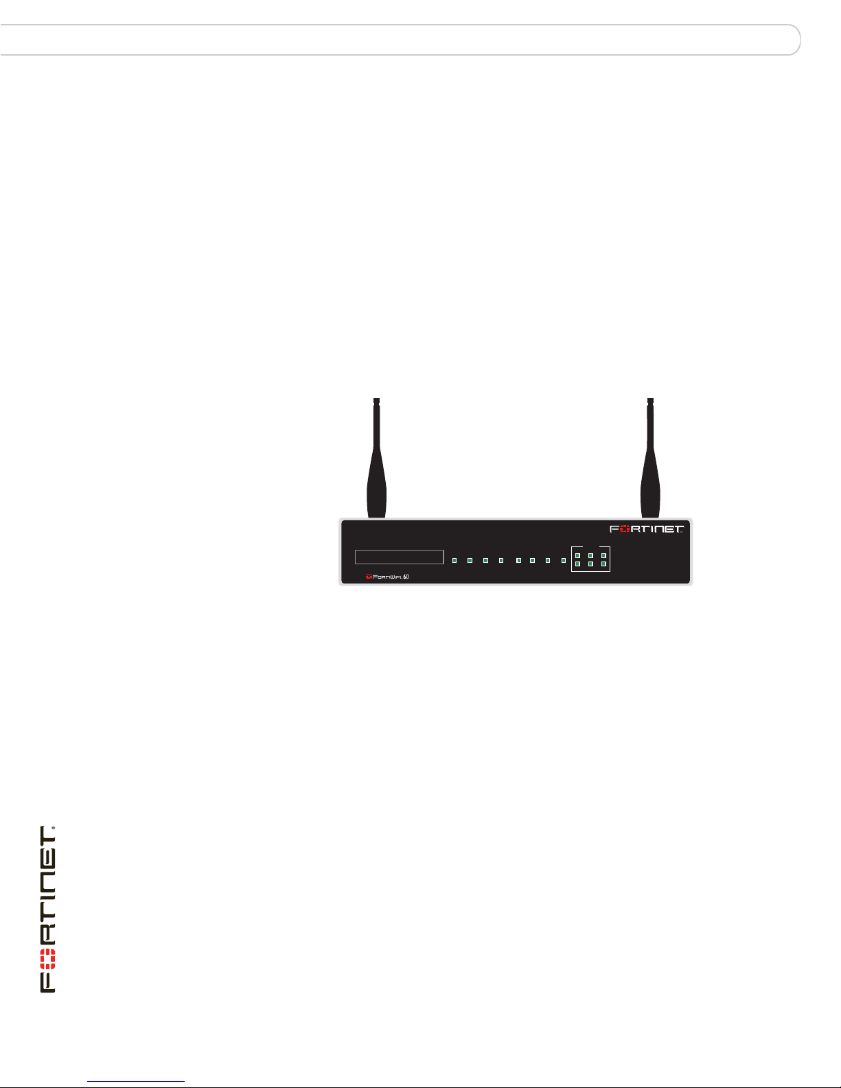
Figure 1: FortiWiFi-60B
About this document
This document explains how to install and configure your FortiWiFi unit onto your
network. This document also includes how to install and upgrade new firmware
versions on your FortiWiFi unit.
This document contains the following chapters:
• Installing – Describes setting up and powering on a FortiWiFi unit.
• Configuring – Provides an overview of the operating modes of the FortiWiFi
unit and how to integrate the FortiWiFi unit into your network.
• Advanced configuration – Describes additional configuration you can perform
on the FortiWiFi unit to enhance network protection, including antivirus,
antispam, firewall configuration and logging.
• Using a wireless network – Describes strategies for installing a wireless
device, and how to configure the FortiWiFi for a wireless network.
• FortiWiFi Firmware – Describes how to install, update, restore and test
firmware for the FortiWiFi device.
INTERNAL
1
3
5
DMZ
B
WAN 1Wifi WAN 2POWER STATUS HA ALARM
2
4
6
FortiWiFi-60B FortiOS 3.0 MR6 Install Guide
8 01-30006-0447-20080131
Introduction Further Reading
Document conventions
The following document conventions are used in this guide:
• In the examples, private IP addresses are used for both private and public IP
addresses.
• Notes and Cautions are used to provide important information:
Note: Highlights useful additional information.
Caution: Warns you about commands or procedures that could have unexpected or
!
undesirable results including loss of data or damage to equipment.
Typographic conventions
FortiWiFi documentation uses the following typographical conventions:
Convention Example
Keyboard input In the Gateway Name field, type a name for the remote VPN
Code examples config sys global
CLI command syntax config firewall policy
Document names FortiGate Administration Guide
Menu commands Go to VPN > IPSEC > Phase 1 and select Create New.
Program output Welcome!
Variables
peer or client (for example, Central_Office_1).
set ips-open enable
end
edit id_integer
set http_retry_count <retry_integer>
set natip <address_ipv4mask>
end
<address_ipv4>
Further Reading
The most up-to-date publications and previous releases of Fortinet product
documentation are available from the Fortinet Technical Documentation web site
at http://docs.forticare.com.
The following FortiWiFi product documentation is available:
• FortiWiFi QuickStart Guide
Provides basic information about connecting and installing a FortiWiFi unit.
• FortiGate Administration Guide
Provides basic information about how to configure a FortiWiFi unit, including
how to define FortiWiFi protection profiles and firewall policies; how to apply
intrusion prevention, antivirus protection, web content filtering, and spam
filtering; and how to configure a VPN.
FortiWiFi-60B FortiOS 3.0 MR6 Install Guide
01-30006-0447-20080131 9

Further Reading Introduction
• FortiWiFi online help
Provides a context-sensitive and searchable version of the Administration
Guide in HTML format. You can access online help from the web-based
manager as you work.
• FortiGate CLI Reference
Describes how to use the FortiWiFi CLI and contains a reference to all
FortiWiFi CLI commands.
• FortiGate Log Message Reference
Available exclusively from the Fortinet Knowledge Center, the FortiGate Log
Message Reference describes the structure of FortiGate log messages and
provides information about the log messages that are generated by FortiWiFi
units.
• FortiGate High Availability User Guide
Contains in-depth information about the high availability feature and the
clustering protocol.
• FortiGate IPS User Guide
Describes how to configure the FortiWiFi Intrusion Prevention System settings
and how the FortiGate IPS deals with some common attacks.
• FortiGate IPSec VPN User Guide
Provides step-by-step instructions for configuring IPSec VPNs using the
web-based manager.
• FortiGate SSL VPN User Guide
Compares FortiGate IPSec VPN and FortiGate SSL VPN technology, and
describes how to configure web-only mode and tunnel-mode SSL VPN access
for remote users through the web-based manager.
• FortiGate PPTP VPN User Guide
Explains how to configure a PPTP VPN using the web-based manager.
• FortiGate Certificate Management User Guide
Contains procedures for managing digital certificates including generating
certificate requests, installing signed certificates, importing CA root certificates
and certificate revocation lists, and backing up and restoring installed
certificates and private keys.
• FortiGate VLANs and VDOMs User Guide
• Describes how to configure VLANs and VDOMS in both NAT/Route and
Transparent mode. Includes detailed examples.
Fortinet Knowledge Center
The Knowledge Center contains troubleshooting and how-to articles, FAQs,
technical notes, and more. Visit the Fortinet Knowledge Center at
http://kc.forticare.com.
Comments on Fortinet technical documentation
Please send information about any errors or omissions in this document, or any
Fortinet technical documentation, to techdoc@fortinet.com.
FortiWiFi-60B FortiOS 3.0 MR6 Install Guide
10 01-30006-0447-20080131

Introduction Customer service and technical support
Customer service and technical support
Fortinet Technical Support provides services designed to make sure that your
Fortinet systems install quickly, configure easily, and operate reliably in your
network.
Please visit the Fortinet Technical Support web site at http://support.fortinet.com
to learn about the technical support services that Fortinet provides.
FortiWiFi-60B FortiOS 3.0 MR6 Install Guide
01-30006-0447-20080131 11

Customer service and technical support Introduction
FortiWiFi-60B FortiOS 3.0 MR6 Install Guide
12 01-30006-0447-20080131

Installing Environmental specifications
Installing
This chapter describes installing your FortiWiFi unit in your server room,
environmental specifications and how to mount the FortiWiFi in a rack if
applicable.
This chapter contains the following topics:
• Environmental specifications
• Cautions and warnings
• Plugging in the FortiWiFi
• Plugging in the FortiWiFi
• Turning off the FortiWiFi unit
Environmental specifications
• Operating temperature: 32 to 104°F (0 to 40°C)
If you install the FortiWiFi unit in a closed or multi-unit rack assembly, the
operating ambient temperature of the rack environment may be greater than
room ambient temperature. Therefore, make sure to install the equipment in
an environment compatible with the manufacturer's maximum rated ambient
temperature.
• Storage temperature: -13 to 158°F (-25 to 70°C)
• Humidity: 5 to 90% non-condensing
• Air flow - For rack installation, make sure that the amount of air flow required
for safe operation of the equipment is not compromised.
• For free-standing installation, make sure that the appliance has at least 1.5 in.
(3.75 cm) of clearance on each side to allow for adequate air flow and cooling.
This device complies with part FCC Class A, Part 15, UL/CUL, C Tick, CE
and VCCI. Operation is subject to the following two conditions:
• This device may not cause harmful interference, and
• This device must accept any interference received, including interference that
may cause undesired operation.
This equipment has been tested and found to comply with the limits for a Class B
digital device, pursuant to part 15 of the FCC Rules. These limits are designed to
provide reasonable protection against harmful interference in a residential
installation. This equipment generates, uses and can radiate radio frequency
energy and, if not installed and used in accordance with the instructions, may
cause harmful interference to radio communications. However, there is no
guarantee that interference will not occur in a particular installation. If this
equipment does cause harmful interference to radio or television reception, which
can be determined by turning the equipment off and on, the user is encouraged to
try to correct the interference by one or more of the following measures:
• Reorient or relocate the receiving antenna.
• Increase the separation between the equipment and receiver.
FortiWiFi-60B FortiOS 3.0 MR6 Install Guide
01-30006-0447-20080131 13

Cautions and warnings Installing
• Connect the equipment into an outlet on a circuit different from that to which
the receiver is connected.
• Consult the dealer or an experienced radio/TV technician for help.
The equipment compliance with FCC radiation exposure limit set forth for
uncontrolled Environment.
Cautions and warnings
Review the following cautions before installing your FortiWiFi unit.
Grounding
• Ensure the FortiWiFi unit is connected and properly grounded to a lightning
and surge protector. WAN or LAN connections that enter the premises from
outside the building should be connected to an Ethernet CAT5 (10/100 Mb/s)
surge protector.
• Shielded Twisted Pair (STP) Ethernet cables should be used whenever
possible rather than Unshielded Twisted Pair (UTP).
• Do not connect or disconnect cables during lightning activity to avoid damage
to the FortiWiFi unit or personal injury.
Rack mount instructions
Elevated Operating Ambient - If installed in a closed or multi-unit rack assembly,
the operating ambient temperature of the rack environment may be greater than
room ambient. Therefore, consideration should be given to installing the
equipment in an environment compatible with the maximum ambient temperature
(Tma) specified by the manufacturer.
Reduced Air Flow - Installation of the equipment in a rack should be such that
the amount of air flow required for safe operation of the equipment is not
compromised.
Mechanical Loading - Mounting of the equipment in the rack should be such that
a hazardous condition is not achieved due to uneven mechanical loading.
Circuit Overloading - Consideration should be given to the connection of the
equipment to the supply circuit and the effect that overloading of the circuits might
have on overcurrent protection and supply wiring. Appropriate consideration of
equipment nameplate ratings should be used when addressing this concern.
Reliable Earthing - Reliable earthing of rack-mounted equipment should be
maintained.
Particular attention should be given to supply connections other than direct
connections to the branch circuit (e.g. use of power strips).
Mounting
If required to fit into a rack unit, remove the rubber feet from the bottom of the
FortiWiFi unit.
Adhere the rubber feet included in the package to the underside of the FortiWiFi
unit, near the corners of the device.
FortiWiFi-60B FortiOS 3.0 MR6 Install Guide
14 01-30006-0447-20080131
Installing Setting up a wireless network
Place the FortiWiFi unit on any flat, stable surface. Ensure the unit has at least 1.5
inches (3.75 cm) of clearance on each side to ensure adequate airflow for cooling.
Alternatively, you can use the mounting brackets to mount the FortiWiFi to a wall.
To attach the mounting brackets, place the bracket so that the flat portion is away
from the FortiWifi, and the bracket is supported by the bracket side bars. Use the
four screws supplied to attach the bracket to the FortiWiFi unit. Repeat for the
other bracket. See the illustration below for how the bracket is attached.
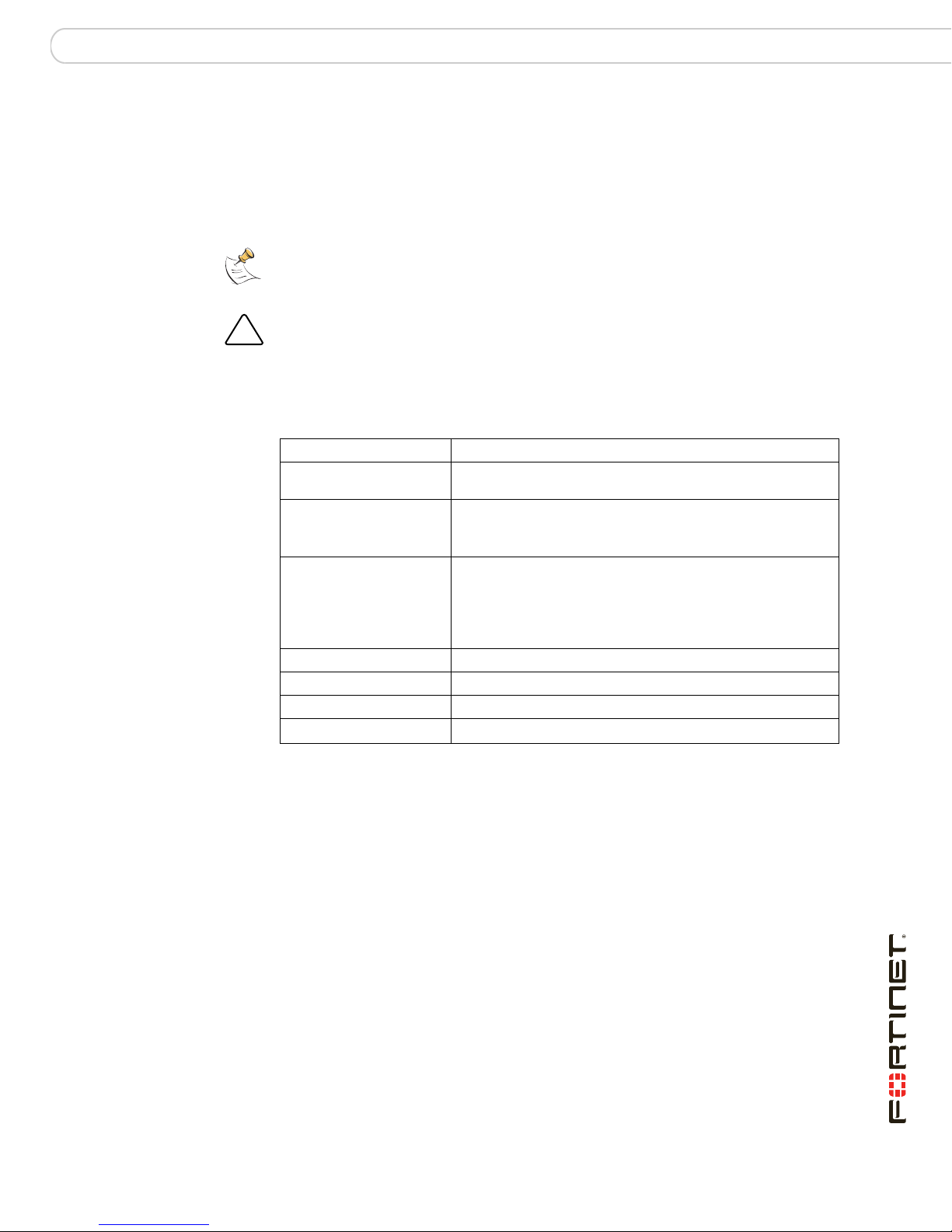
Figure 2: FortiWiFi with attached mounting bracket
To mount to the wall, measure where the holes in the brackets are on the wall, and
inser nails or screws. Hang the FortiWiFi on the nails or screws from the brackets.
Setting up a wireless network
When placing the FortiWiFi access point (AP), your main concern is providing a
strong signal to all users. A strong signal ensures a fast connection and the
efficient transfer of data. A weaker signal means a greater chance of data
transmission errors and the need to re-send information, slowing down data
transfer.
Consider the following guidelines when placing the FortiWiFi AP:
• Physical barriers can impede the radio signals. Solid objects such as walls,
furniture and people absorb radio waves, weakening the signal. Be aware of
the physical barriers in your office space that may reduce a signal. If there is
enough physical interference, you may encounter dead spots that receive no
signals.
• Ensure the FortiWiFi AP is located in a prominent location within a room for
maximum coverage, rather than in a corner.
• Construction materials used in a building can also weaken radio signals.
Rooms with walls of concrete or metal can affect the signal strength.
FortiWiFi-60B FortiOS 3.0 MR6 Install Guide
01-30006-0447-20080131 15
Setting up a wireless network Installing
Radio Frequency interface
The 802.11b/g standard uses a frequency range of 2.4 to 2.483 GHz and the
802.11a standard transmit at 5 GHz. Radio frequency (RF) interference occurs
when other devices send RF signals during their normal operation that use the
same frequency as the FortiWiFi AP. Wireless devices such as cordless phones,
microwave ovens and Bluetooth devices can interfere with packet transmissions
on a wireless network.
To avoid RF interference:
• Remove these devices from the immediate area where users are working.
Something as simple as a Bluetooth enabled mouse may cause transmission
interruptions.
• Keep the FortiWiFi AP and wireless devices at least 10 feet away from
appliances such as microwave ovens and cordless phones.
• If you must have a cordless phone, select one that does not use the 2.4GHz
frequency range for b/g or 5GHZ frequency range for wireless a.
• Consider more FortiWiFi APs to help strengthen the signal. The weaker the
signal, the slower the transmission will be as it tries to compete against other
wireless devices.
• Set a channel that users and FortiWiFi APs will specifically use can improve
signal quality.
Using multiple access points
If you cannot avoid some of these impediments due to the shape of the office or
building materials used, you may need to use multiple FortiWiFi APs to help
distribute the radio signal around the room. Figure 3 shows how positioning two
FortiWiFi APs within a uniquely shaped office space helps to distribute signals
around the area.
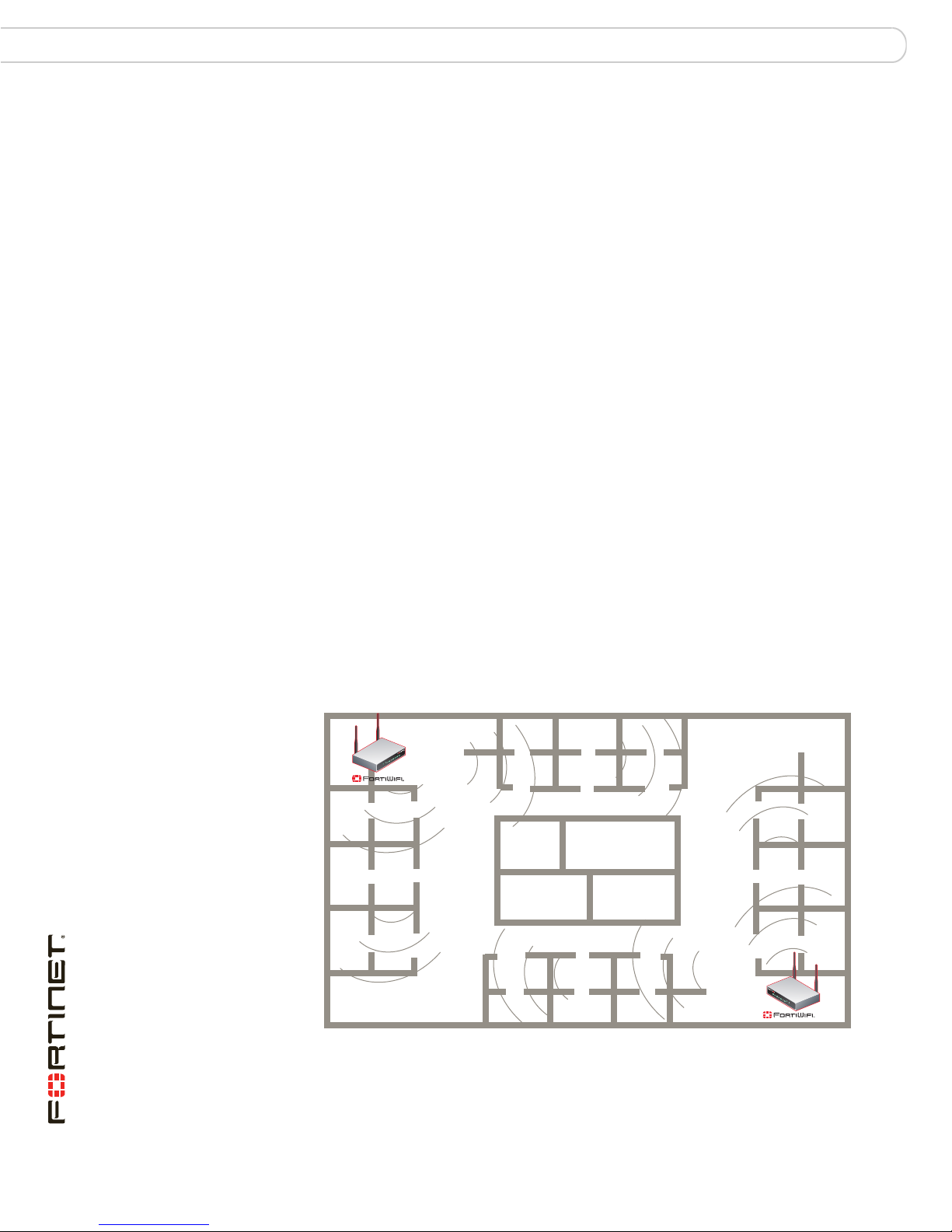
Figure 3: Using multiple APs to provide a constant strong signal.
Stairs
Washrooms
Elevator
FortiWiFi-60B FortiOS 3.0 MR6 Install Guide
16 01-30006-0447-20080131

Installing Plugging in the FortiWiFi
This sample office has washrooms, a stairwell and an elevator shaft in the center
of the building, making it impossible to use a single FortiWiFi AP effectively. The
elevator shaft and multiple metal stalls in the washrooms can cause signal
degradation. However, placing a FortiWiFi AP in opposite corners of the office
provides maximum coverage.
When using multiple APs, each FortiWiFi AP should be set to a different channel
to avoid interference in areas where signals from both FortiWiFi units can be
received.
Plugging in the FortiWiFi
Use the following steps to connect the power supply to the FortiGate unit.
To power on the FortiGate unit
1 Connect the AC adapter to the power connection at the back of the FortiGate unit.
2 Connect the AC adapter to the power cable.
3 Connect the power cable to a power outlet.
The FortiGate unit starts and the Power and Status LEDs light up. The Status
LEDs flash while the FortiGate unit starts up, and remain lit when the system is
running.
Connecting to the network
Using the supplied Ethernet cable, connect one end of the cable to your router or
modem, whatever the connection is to the Internet. Connect the other end to the
FortiWiFi unit. Connect to either the External, WAN port, or port 1. Connect
additional cable to the Internal port or port 2 and your internal hub or switch.
Turning off the FortiWiFi unit
Always shut down the FortiWiFi operating system properly before turning off the
power switch to avoid potential hardware problems.
To power off the FortiWiFi unit
1 From the web-based manager, go to System > Status.
2 In the Unit Operation display, select Shutdown, or from the CLI enter:
execute shutdown
3 Disconnect the power cables from the power supply.
FortiWiFi-60B FortiOS 3.0 MR6 Install Guide
01-30006-0447-20080131 17

Turning off the FortiWiFi unit Installing
FortiWiFi-60B FortiOS 3.0 MR6 Install Guide
18 01-30006-0447-20080131
Configuring NAT vs. Transparent mode
Configuring
This section provides an overview of the operating modes of the FortiWiFi unit,
NAT/Route and Transparent, and how to configure the FortiWiFi unit for each
mode. There are two ways you can configure the FortiWiFi unit, using the
web-based manager or the command line interface (CLI). This section will step
through using both methods. Use whichever you are most comfortable with.
This section includes the following topics:
• NAT vs. Transparent mode
• Connecting to the FortiWiFi unit
• Verify the configuration
• Backing up the configuration
• Additional configuration
NAT vs. Transparent mode
NAT mode
The FortiWiFi unit can run in two different modes, depending on your network
infrastructure and requirements. You have a choice between NAT/Route mode
and Transparent mode. Both include the same robust network security features
such as antispam, antivirus, VPN and firewall policies.
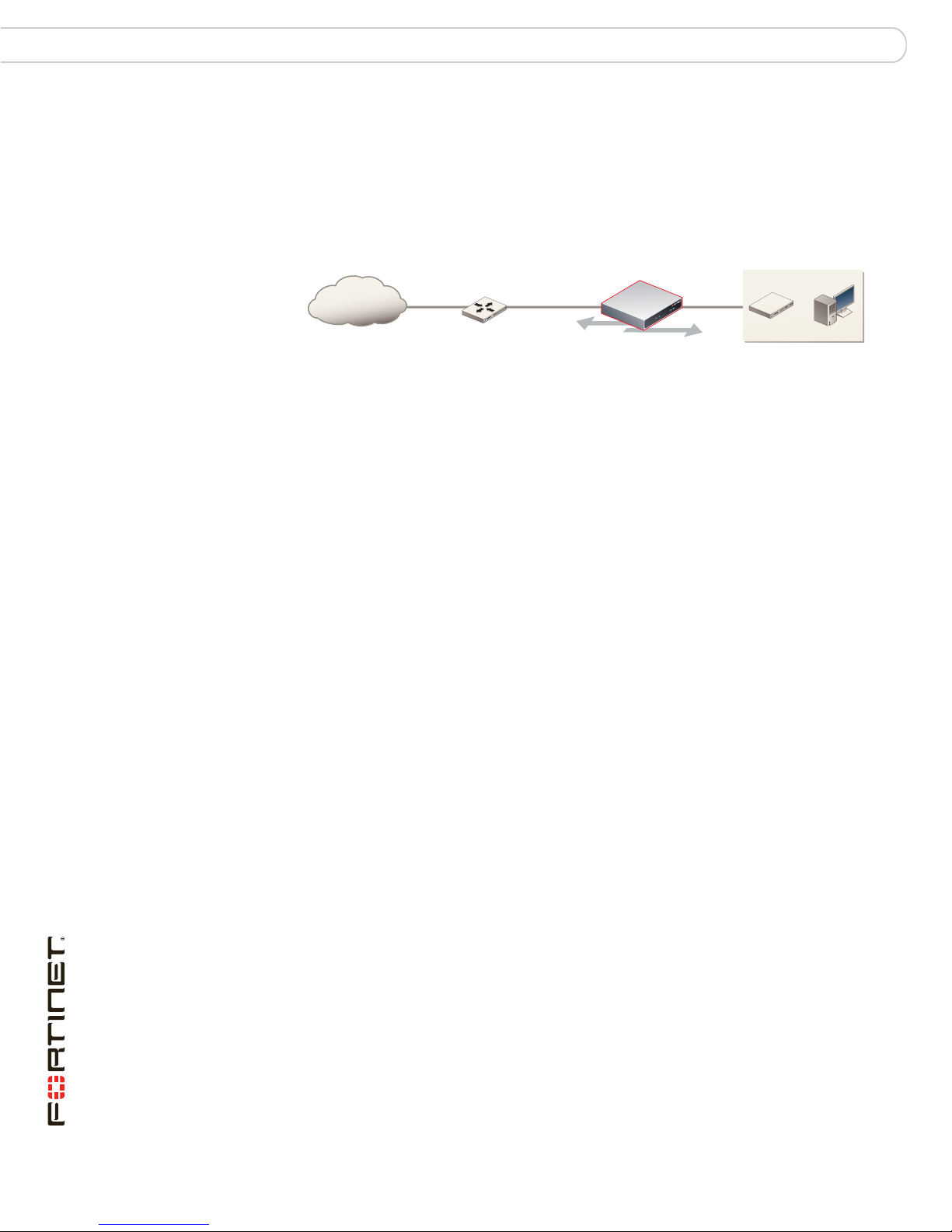
In NAT/Route mode, the FortiWiFi unit is visible to the network. Like a router, all its
interfaces are on different subnets.
In NAT mode, each port is on a different subnet, enabling you to have a single IP
address available to the public Internet. The FortiWiFi unit performs network
address translation before it sends and receives the packet to the destination
network.
In Route mode, there is no address translation.
Figure 4: FortiWiFi unit in NAT mode
Internal network
Internet
Router
NAT mode policies controlling
traffic between internal
and external networks.
192.168.1.99204.23.1.5
192.168.1.20
You typically use NAT/Route mode when the FortiWiFi unit is operating as a
gateway between private and public networks. In this configuration, you would
create NAT mode firewall policies to control traffic flowing between the internal,
private network and the external, public network, usually the Internet.
FortiWiFi-60B FortiOS 3.0 MR6 Install Guide
01-30006-0447-20080131 19
Connecting to the FortiWiFi unit Configuring
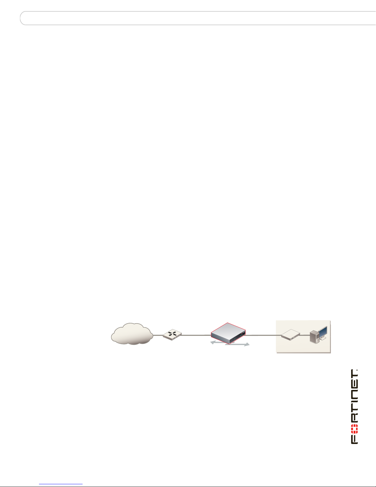
Transparent mode
In Transparent mode, the FortiWiFi unit is invisible to the network. Similar to a
network bridge, all FortiGate interfaces must be on the same subnet. You only
have to configure a management IP address to make configuration changes. The
management IP address is also used for antivirus and attack definition updates.
Figure 5: FortiWiFi unit in Transparent mode
10.10.10.1
Internet
Gateway to public network
204.23.1.2 10.10.10.2
External
Management IP
Internal
Internal Network
Router
You typically use the FortiWiFi unit in Transparent mode on a private network
behind an existing firewall or behind a router. The FortiWiFi unit performs firewall
functions, IPSec VPN, virus scanning, IPS web filtering, and Spam filtering.
Connecting to the FortiWiFi unit
To configure, maintain and administer the FortiWiFi unit, you need to connect to it.
There are two methods for these tasks:
• using the web-based manger, a GUI interface using a current web browser
such as FireFox or Internet Explorer.
• using the command line interface (CLI), a command line interface similar to
DOS or UNIX commands using an SSH terminal or Telnet terminal.
Connecting to the web-based manager
To connect to the web-based manager, you require:
• a computer with an Ethernet connection
• Microsoft Internet Explorer version 6.0 or higher or any recent version of the
most popular web browser
• an Ethernet cable.
Transparent mode policies
controlling traffic between
internal and external networks.
10.10.10.3
To connect to the web-based manager
1 Set the IP address of the management computer to the static IP address
192.168.1.2 with a netmask of 255.255.255.0.
2 Using the Ethernet cable, connect the internal interface of the FortiWiFi unit to the
computer Ethernet connection.
3 Start your browser and enter the address https://192.168.1.99. (remember to
include the “s” in https://).
FortiWiFi-60B FortiOS 3.0 MR6 Install Guide
20 01-30006-0447-20080131

Configuring Connecting to the FortiWiFi unit
To support a secure HTTPS authentication method, the FortiWiFi unit ships with a
self-signed security certificate, which is offered to remote clients whenever they
initiate a HTTPS connection to the FortiWiFi unit. When you connect, the
FortiWiFi unit displays two security warnings in a browser.
The first warning prompts you to accept and optionally install the FortiWiFi unit’s
self-signed security certificate. If you do not accept the certificate, the FortiWiFi
unit refuses the connection. If you accept the certificate, the FortiGate login page
appears. The credentials entered are encrypted before they are sent to the
FortiWiFi unit. If you choose to accept the certificate permanently, the warning is
not displayed again.
Just before the FortiGate login page is displayed, a second warning informs you
that the FortiGate certificate distinguished name differs from the original request.
This warning occurs because the FortiWiFi unit redirects the connection. This is
an informational message. Select OK to continue logging in.
4 Type admin in the Name field and select Login.
Connecting to the CLI
To connect to the FortiGate CLI you require:
• a computer with an available communications port
• a serial cable, either a RJ-45 to DB-9 or null modem cable, whichever was
included in your FortiGate package
• terminal emulation software such as HyperTerminal for Microsoft Windows
Note: The following procedure uses Microsoft Windows HypterTerminal software. You can
apply these steps to any terminal emulation program.
To connect to the CLI
1 Connect the serial cable to the communications port of your computer and to the
FortiGate console port.
2 Start HyperTerminal, enter a name for the connection and select OK.
3 Configure HyperTerminal to connect directly to the communications port on your
computer and select OK.
4 Select the following port settings and select OK:
Bits per second 9600
Data bits 8
Parity None
Stop bits 1
Flow control None
5 Press Enter to connect to the FortiGate CLI.
6 When the login prompt appears, type admin and press Enter twice.
Type ? to list available commands. For information about how to use the CLI, see
the FortiGate CLI Reference.
FortiWiFi-60B FortiOS 3.0 MR6 Install Guide
01-30006-0447-20080131 21

Configuring NAT mode Configuring
Configuring NAT mode
Configuring NAT mode involves defining interface addresses and default routes,
and simple firewall policies. You can use the web-based manager or the CLI to
configure the FortiWiFi unit in NAT/Route mode.
Using the web-based manager
After connecting to the web-based manager, you can use the following procedures
to complete the basic configuration of the FortiWiFi unit. Ensure you read the
section “Connecting to the web-based manager” on page 20 before beginning.
Configure the interfaces
When shipped, the FortiWiFi unit has a default address of 192.168.1.99 and a
netmask of 255.255.255.0. for either the Port 1 or Internal interface. You need to
configure this and other ports for use on your network.
To configure interfaces
1 Go to System > Network > Interface.
2 Select the edit icon for an interface.
3 Set the Addressing Mode for the interface.
• For Manual addressing, enter the IP address and netmask for the interface.
• For DHCP addressing, select DHCP and complete the following:
Distance Enter the administrative distance, between 1 and 255 for the
Retrieve default gateway
from server
Override internal DNS Enable to use the DNS addresses retrieved from the DHCP
default gateway retrieved from the DHCP server. The
administrative distance specifies the relative priority of a route
when there are multiple routes to the same destination. A
lower administrative distance indicates a more preferred route.
Enable to retrieve a default gateway IP address from the
DHCP server. The default gateway is added to the static
routing table.
server instead of the DNS server IP addresses on the DNS
page on System > Network > Options. On FortiWiFi-100
units and lower, you should also enable Obtain DNS server
address automatically in System > Network > Options.
• For PPPoE addressing, select PPPoE, and complete the following:
Username Enter the username for the PPPoE server. This may have
Password Enter the password for the PPPoE server for the above user
Unnumbered Specify the IP address for the interface. If your ISP has
Initial Disc Timeout Initial discovery timeout in seconds. The time to wait before
been provided by your ISP.
name.
assigned you a block of IP addresses, use one of these IP
addresses. Alternatively, you can use, or borrow, the IP
address of a configured interface on the router. You may need
to do this to minimize the number of unique IP addresses
within your network.
If you are borrowing an IP address remember the interface
must be enabled, or up to function correctly.
starting to retry a PPPoE discovery. To disable the discovery
timeout, set the value to 0.
FortiWiFi-60B FortiOS 3.0 MR6 Install Guide
22 01-30006-0447-20080131

Configuring Configuring NAT mode
Initial PADT Timeout Initial PPPoE Active Discovery Terminate (PADT) timeout in
Distance Enter the administrative distance, between 1 and 255 for the
Retrieve default gateway
from server
Override internal DNS Enable to use the DNS addresses retrieved from the DHCP
seconds. Use this timeout to shut down the PPPoE session if it
is idle for this number of seconds. Your ISP must support
PADT. To disable the PADT timeout, set the value to 0.
default gateway retrieved from the DHCP server. The
administrative distance specifies the relative priority of a route
when there are multiple routes to the same destination. A
lower administrative distance indicates a more preferred route.
Enable to retrieve a default gateway IP address from the
DHCP server. The default gateway is added to the static
routing table.
server instead of the DNS server IP addresses on the DNS
page on System > Network > Options. On FortiWiFi-100
units and lower, you should also enable Obtain DNS server
address automatically in System > Network > Options.
4 Select OK.
5 Repeat this procedure for each interface as required.
Note: If you change the IP address of the interface you are connecting to, you must
connect through a web browser again using the new address. Browse to https:// followed by
the new IP address of the interface. If the new IP address of the interface is on a different
subnet, you may have to change the IP address of your computer to the same subnet.
Configure a DNS server
A DNS server is a service that converts symbolic node names to IP addresses. A
domain name server (DNS server) implements the protocol. In simple terms, it
acts as a phone book for the Internet. A DNS server matches domain names with
the computer IP address. This enables you to use readable locations, such as
fortinet.com when browsing the Internet.
DNS server IP addresses are typically provided by your internet service provider.
To configure DNS server settings
1 Go to System > Network > Options.
2 Enter the IP address of the primary DNS server.
3 Enter the IP address of the secondary DNS server.
4 Select Apply.
Adding a default route and gateway
A route provides the FortiWiFi unit with the information it needs to forward a
packet to a particular destination. A static route causes packets to be forwarded to
a destination other than the default gateway. You define static routes manually.
Static routes control traffic exiting the FortiWiFi unit-you can specify through which
interface the packet will leave and to which device the packet should be routed.
In the factory default configuration, entry number 1 in the Static Route list is
associated with a destination address of 0.0.0.0/0.0.0.0, which means any/all
destinations. This route is called the "static default route". If no other routes are
present in the routing table and a packet needs to be forwarded beyond the
FortiWiFi unit, the factory configured static default route causes the FortiWiFi unit
to forward the packet to the default gateway.
FortiWiFi-60B FortiOS 3.0 MR6 Install Guide
01-30006-0447-20080131 23

Configuring NAT mode Configuring
For an initial configuration, you must edit the factory configured static default route
to specify a different default gateway for the FortiWiFi unit. This will enable the
flow of data through the FortiWiFi unit.
For details on adding additional static routes, see the FortiGate Administration
Guide.
To modify the default gateway
1 Go to Router > Static.
2 Select Edit for the default route
3 In the Gateway field, type the IP address of the next-hop router where outbound
traffic is directed.
4 If the FortiWiFi unit reaches the next-hop router through a different interface
(compared to the interface that is currently selected in the Device field), select the
name of the interface from the Device field.
5 Select OK.
Adding firewall policies
Firewall policies enable traffic to flow through the FortiWiFi interfaces. Firewall
policies define how the FortiWiFi unit processes the packets in a communication
session. You can configure the firewall policies to allow only specific traffic, users
and specific times when traffic is allowed.
For the initial installation, a single firewall policy that enables all traffic through will
enable you to verify your configuration is working. On lower-end units such a
default firewall policy is already in place. For the higher end FortiWiFi units, you
will need to add a firewall policy.
The following steps add two policies that allows all traffic through the FortiWiFi
unit, to enable you to continue testing the configuration on the network.
To add an outgoing traffic firewall policy
1 Go to Firewall > Policy.
2 Select Create New.
3 Set the following and select OK.
Source Interface Select the port connected to the network.
Source Address All
Destination Interface Select the port connected to the Internet.
Destination Address All
Schedule always
Service Any
Action Accept
To add an incoming traffic firewall policy
1 Go to Firewall > Policy.
2 Select Create New.
FortiWiFi-60B FortiOS 3.0 MR6 Install Guide
24 01-30006-0447-20080131

Configuring Configuring NAT mode
3 Set the following and select OK.
Source Interface Select the port connected to the Internet.
Source Address All
Destination Interface Select the port connected to the network.
Destination Address All
Schedule always
Service Any
Action Accept
Firewall policy configuration is the same in NAT/Route mode and Transparent
mode.
Note that these policies allow all traffic through. No protection profiles have been
applied. Ensure you create additional firewall policies to accommodate your
network requirements.
For details, see the FortiGate Administration Guide.
Using the CLI
After connecting to the CLI, you can use the following procedures to complete the
basic configuration of the FortiWiFi unit. Ensure you read the section “Connecting
to the CLI” on page 21 before beginning.
Configure the interfaces
When shipped, the FortiWiFi unit has a default address of 192.168.1.99 and a
netmask of 255.255.255.0. for either the Port 1 or Internal interface. You need to
configure this and other ports for use on your network.
To set an interface to use a static address
config system interface
edit <interface_name>
set mode static
set ip <address_ip> <netmask>
end
To set an interface to use DHCP addressing
config system interface
edit external
set mode dhcp
set distance <integer>
set defaultgw {enable | disable}
set dns-server-override {enable | disable}
end
FortiWiFi-60B FortiOS 3.0 MR6 Install Guide
01-30006-0447-20080131 25
 Loading...