

Fortinet FortiWiFi FortiWiFi-60A, FortiWiFi-60AM Quick Start Manual
© Copyright 2007 Fortinet Incorporated. All rights reserved.
Products mentioned in this document are trademarks or registered trademarks of their respective holders.
Regulatory Compliance
FCC Class A Part 15 CSA/CUS
17 May 2007
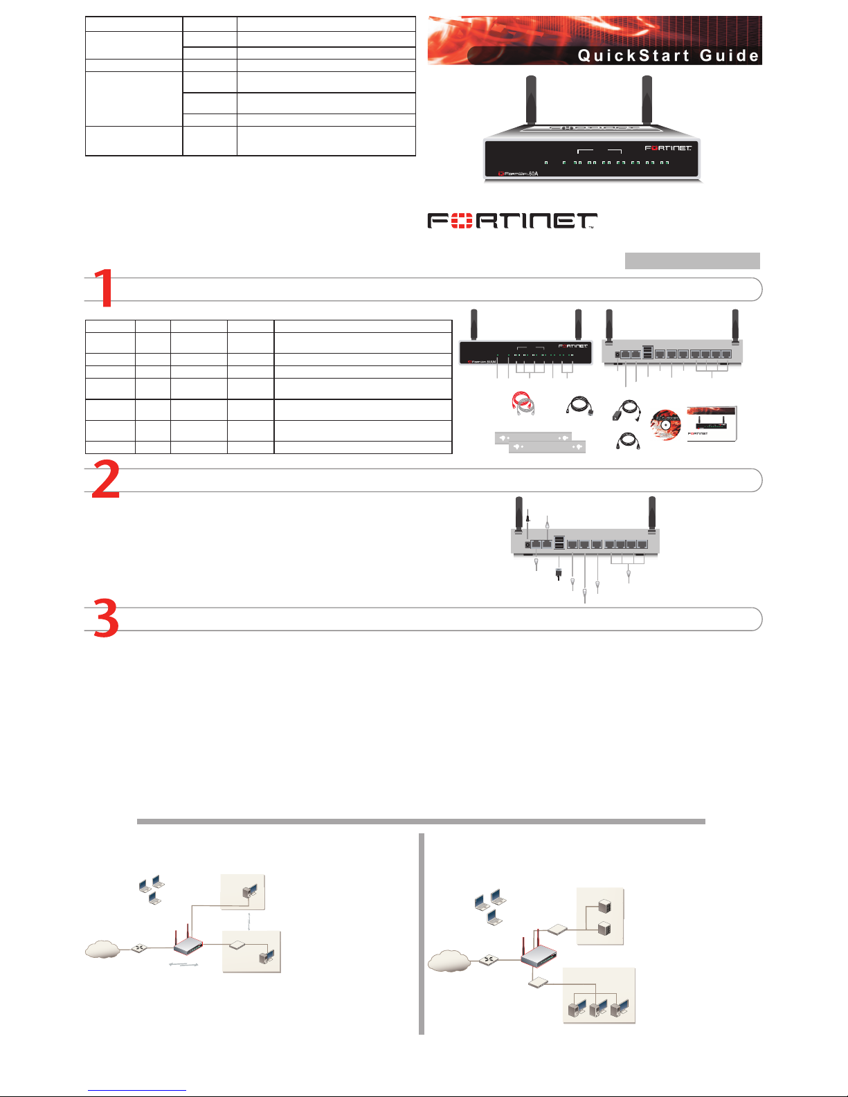
Checking the Package Contents
Connecting
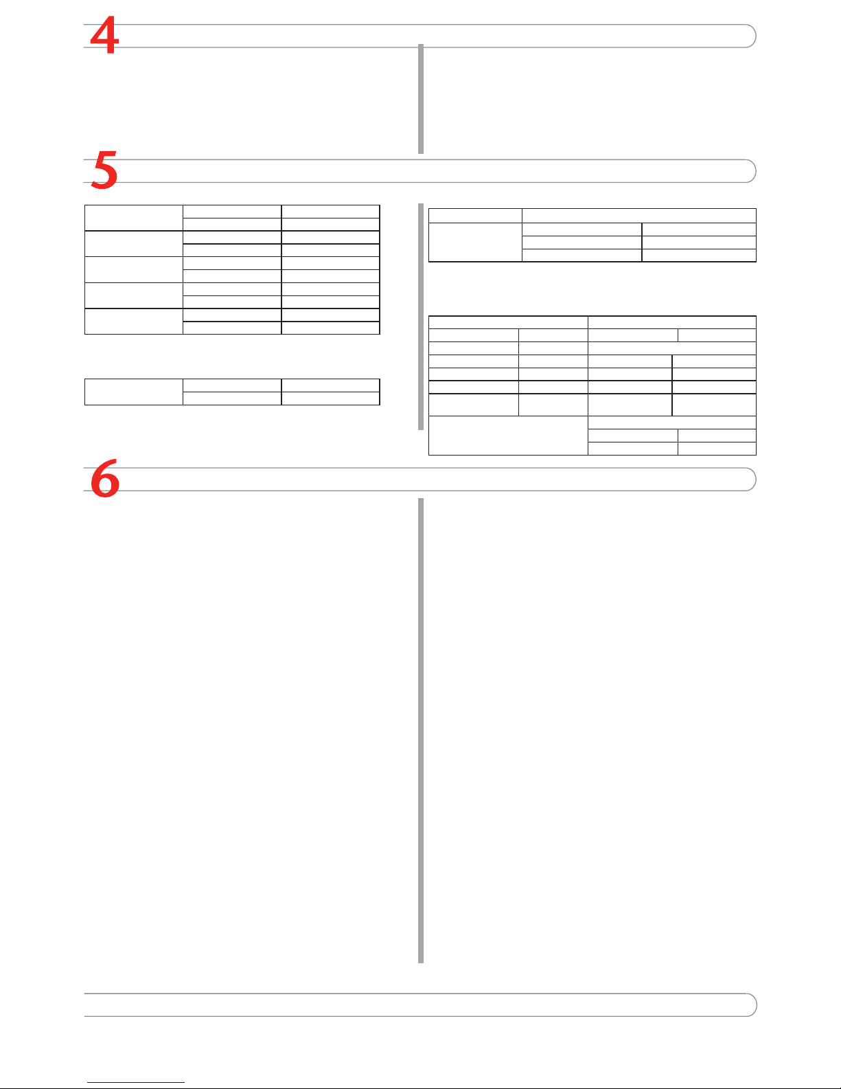
Planning the Configuration
INTERNAL
DMZ4321
LINK 100 LINK 100 LINK 100 LINK 100 LINK 100 LINK 100 LINK 100
WAN1 WAN2
PWR WLAN
Ethernet Cables:
Orange - Crossover
Grey - St raight-thro ugh
Power Cab le
Power Sup ply
INTERNAL
DMZ4321
LINK 100 LINK 100 LINK 100 LINK 100 LINK 100 LINK 100 LINK 100
WAN1 WAN2
PWR WLAN
Power
LED
WLAN
LED
WAN 1,2
Interface
DMZ
Interface
Internal
Interface
Front
Internal Interface,
switch co nnectors
1,2,3,4
Back
1234
USB
WAN2 WAN1 DMZ
DC+12V
Internal
Power
Connectio n
USB
WAN2
DMZ
WAN1
RJ-45 Serial
Connection
Modem
Connection
(FortiWiFi-60AM)
Modem Console
RJ-45 to
DB-9 Seria l Cable
2 Mountin g Brackets
Documen tation
FortiWiFi-60A/AM
Copyright 2006 Fortinet Incorpo rated. All rights reser ved.
Trademarks
Products mentioned in this docu ment are tr ademarks.
Qui c k St a r t G ui d e
INTERNAL
DMZ4321
LINK 100LINK 100 LINK 100LINK 100 LINK 100 LINK 100 LINK 100
WAN1 WAN2
PWR WLAN
1234
USB
WAN2 WAN1 DMZ
DC+12V
Internal
Optional connection to DMZ net work
Straight -through Et hernet cabl e connects
to Inter net (public switch, ro uter or mod em)
Straight -through
Ethernet cables con nect
to compu ters on int ernal netwo rk
Power ca ble connect s to power supply
Optional redundant connection to Internet
Modem co nnection (F ortiWiFi-60 AM)
Optional connection to a seria l modem
(FortiWi Fi-60A)
Modem Console
Optional RJ-45 to D B-9 serial cable
connects to managem ent compute r
Connector Type Speed Protocol Description
Internal RJ-45 10/100 Base-T Ethernet 4-port switch connection to up to four devices or the
internal network.
WLAN Antenna 802.11 a/b/g Wireless connections to LAN.
WAN1 and 2 RJ-45 10/100 Base-T Ethernet Redundant connections to the Internet.
DMZ RJ-45 10/100 Base-T Ethernet Optional connection to a DMZ network or to other
FortiWiFi-60A/AM units for high availability (HA).
CONSOLE RJ-45 9600 bps RS-232
serial
Optional connection to the management computer.
Provides access to the command line interface (CLI).
USB USB USB Optional connection for FortiUSB key for rmware
backup and installation.
Phone cable RJ-11 Phone line for internal modem.
Place the unit on a stable surface. It requires 1.5 inches (3.75 cm) clearance above and
on each side to allow for cooling.
Locate the FortiWiFi-60 in a prominent location within a room for maximum coverage,
rather than in a corner.
Be aware of the construction of your environment, concrete and metal walls can hamper
signal strength.
Keep the AP and wireless devices at least 10 feet away from appliances such as microwave ovens and cordless phones.
•
•
•
•
Connect the FortiWiFi unit to a power outlet and to the internal and external networks.
Before beginning to congure the FortiWiFi unit, you need to plan how to integrate the unit into your network. Your conguration plan is dependent upon the operating mode that you select:
NAT/Route mode (the default) or Transparent mode.
NAT/Route mode
In NAT/Route mode, each FortiWiFi unit is visible to the network that it is connected to. All of
its interfaces are on different subnets. Each interface that is connected to a network must be
congured with an IP address
that is valid for that network.
You would typically use NAT/
Route mode when the FortiWiFi
unit is deployed as a gateway
between private and public networks. In its default NAT/Route
mode conguration, the unit
functions as a rewall. Firewall
policies control communications
through the FortiWiFi unit. No
trafc can pass through the
FortiWiFi unit until you add re-
wall policies.
In NAT/Route mode, rewall policies can operate in NAT mode or in Route mode. In NAT
mode, the FortiWiFi unit performs network address translation before IP packets are sent to
the destination network. In Route mode, no translation takes place.
Transparent mode
In Transparent mode, the FortiWiFi unit is invisible to the network. All of its interfaces are on
the same subnet. You only have to congure a management IP address so that you can make
conguration changes.
You would typically use the For-
tiWiFi unit in Transparent mode
on a private network behind
an existing rewall or behind a
router. In its default Transpar-
ent mode conguration, the unit
functions as a rewall. No trafc
can pass through the FortiWiFi
unit until you add rewall policies.
You can connect up to four network segments to the FortiWiFi
unit to control trafc between
these network segments.
Refer to the Documentation CD-ROM for information on how to control trafc, and how to congure HA, antivirus protection, FortiGuard, Web content ltering, Spam ltering,
intrusion prevention (IPS), and virtual private networking (VPN).
FortiWiFi-60A / AM
01-30004-0287-20070517
Quick conguration using the default settings
You can quickly set up your FortiWiFi unit for a home or small ofce using the web-based
manager and the default settings in NAT/Route mode.
All you need to do is set your network computers to use DHCP, access the web-based
manager, and congure the required settings for the WAN1 interface. You can also congure
DNS and a default route if needed. The FortiWiFi unit automatically assigns IP addresses to
up to 100 computers in the internal network.
Connect the FortiWiFi unit to the network.
Set the all the network computers to use DHCP to automatically obtain an IP address.
The FortiGate internal interface acts as a DHCP server for the internal network and assigns
IP addresses to all computers in the range 192.168.1.110 –192.168.1.210.
From the management computer browse to https://192.168.1.99. The FortiGate web-
based manager appears.
Go to System > Network > Interface and select Edit for the WAN1 interface.
1.
2.
3.
4.
Select one of the following Addressing modes
Manual: enter a static IP address and netmask, select OK, and go to step 6
DHCP: to get an IP address from the ISP select DHCP and go to step 9
PPPoE: to get an IP address from the ISP select PPPoE and go to step 9
Go to System > Network > DNS.
Select one of the following DNS settings
Obtain DNS server address automatically: select to get the DNS addresses from the
ISP, select Apply
Use the following DNS server addresses: select and enter the DNS server addresses given to you by the ISP, select Apply
Go to Router > Static, select Create New, enter the default gateway address and select
OK. Network conguration is complete. Proceed to part 7 of this Quick Start Guide.
Select Retrieve default gateway from server and Override internal DNS options if your
ISP supports them, select OK, and proceed to part 7 of this Quick Start Guide.
Go to step 6 if you are not selecting these options.
5.
•
•
•
6.
7.
•
•
8.
9.
LED State Description
Power
Green The FortiGate unit is on.
Off The fortiGate unit is off.
WLAN Green Trafc on WLAN link.
Link
(Internal, DMZ, WAN1,
WAN2)
Green The correct cable is in use and the connected equip-
ment has power.
Flashing
Green
Network activity at this interface.
Off No link established.
100
(Internal, DMZ, WAN1,
WAN2)
Green The interface is connected at 100 Mbps.
Internet
Router
Inter nal
netwo rk
DMZ
10.10.10.1
10.10.10.2
Inter nal Netw ork
192.168.1.3
Internal
192.168.1.99
Wireless
users
Routing policies controlling
traffic between internal
networks.
WAN1
204.23.1.5
NAT mode policies controlling
traffic between internal
and external networks.
Internet
Router
DMZ n et
w
ork
Web Server
Mail Server
Inte rnal
netw ork
Hub or switch
DMZ
WAN1
Internal
Wireless
users
Completing the Configuration
7
Congratulations!
You have nished conguring the basic settings. Your network is now protected from Internetbased threats. To explore the full range of conguration options, see the online help or the
Documentation CD-ROM.
Visit these links for more information and documentation for your Fortinet product.
Technical Documentation - http://docs.forticare.com
Fortinet Knowledge Center - http://kc.forticare.com
Fortinet Technical Support - http://support.fortinet.com
•
•
•
Configuring the FortiWiFi Unit
Collecting Information
NAT/Route Mode
Internal Interface: IP: ____.____.____.____
Netmask: ____.____.____.____
WLAN Interface:
IP: ____.____.____.____
Netmask: ____.____.____.____
WAN1 Interface:
IP: ____.____.____.____
Netmask: ____.____.____.____
WAN2 Interface IP: ____.____.____.____
Netmask: ____.____.____.____
DMZ IP: ____.____.____.____
Netmask: ____.____.____.____
The internal interface IP address and netmask must be valid for the internal network.
Transparent mode
Management IP: IP: ____.____.____.____
Netmask: ____.____.____.____
The management IP address and netmask must be valid for the network from which you will
manage the FortiWiFi unit.
General settings
Administrator password:
Network Settings: Default Gateway:
____.____.____.____
Primary DNS Server: ____.____.____.____
Secondary DNS Server: ____.____.____.____
A default gateway is required for the FortiWiFi unit to route connections to the Internet.
Factory default settings
NAT/Route mode Transparent mode
Internal interface 192.168.1.99 Management IP 0.0.0.0
WAN1 interface 192.168.100.99 Wireless settings
WAN2 interface 192.168.101.99 Mode Access Point
WLAN interface 10.10.80.1 SSID fortinet
DMZ interface 10.10.10.1 Geography World
DHCP server on Internal interface
192.168.1.110
– 192.168.1.210
Channel 5
Administrative account settings
User name admin
Password (none)
Web-based Manager
Connect the FortiWiFi internal interface to a management computer Ethernet interface.
Use a cross-over Ethernet cable to connect the devices directly. Use straight-through
Ethernet cables to connect the devices through a hub or switch.
Congure the management computer to be on the same subnet as the internal
interface of the FortiWiFi unit. To do this, change the IP address of the management
computer to 192.168.1.2 and the netmask to 255.255.255.0.
To access the FortiWiFi web-based manager, start Internet Explorer and browse to
https://192.168.1.99 (remember to include the “s” in https://).
Type admin in the Name eld and select Login.
NAT/Route mode
To change the administrator password
Go to System > Admin > Administrators.
Select Change Password for the admin administrator and enter a new password.
To congure interfaces
Go to System > Network > Interface.
Select the edit icon for each interface to congure.
Set the addressing mode for the interface. (See the online help for information.)
For manual addressing, enter the IP address and netmask for the interface.
For DHCP addressing, select DHCP and any required settings.
For PPPoE addressing, select PPPoE, and enter the username and password
and any other required settings.
To congure the Primary and Secondary DNS server IP addresses
Go to System > Network > Options, enter the Primary and Secondary DNS IP ad-
dresses that you recorded above and select Apply.
To congure a Default Gateway
Go to Router > Static and select Edit icon for the static route.
Set Gateway to the Default Gateway IP address you recorded above and select OK.
Transparent mode
To switch from NAT/route mode to transparent mode
Go to System > Status, select Transparent.
Set the Management IP/Netmask to 192.168.1.99/24.
Set the Default Gateway and select Apply.
To change the administrator password
Go to System > Admin > Administrators.
Select Change Password for the admin administrator and enter a new password.
To change the management interface
Go to System > Cong > Operation Mode.
Enter the Management IP address and netmask that you recorded above and select
Apply.
To congure the Primary and Secondary DNS server IP addresses
Go to System > Network > Options, enter the Primary and Secondary DNS IP ad-
dresses that you recorded above and select Apply.
1.
2.
3.
4.
1.
2.
1.
2.
3.
•
•
•
1.
1.
2.
1.
2.
3.
1.
2.
1.
2.
1.
Command Line Interface
Use the RJ-45 to DB9 cable to connect the FortiWiFi Console port to the management
computer serial port.
Start a terminal emulation program (HyperTerminal) on the management computer. Use
these settings:
Baud Rate (bps) 9600, Data bits 8, Parity None, Stop bits 1, and Flow Control None.
At the Login: prompt, type admin and press Enter twice (no password required).
NAT/Route mode
Congure the FortiWiFi internal interface.
cong system interface
edit internal
set ip <intf_ip>/<netmask_ip>
end
Repeat to congure each interface, for example, to congure the WAN1 interface.
cong system interface
edit wan1
...
Congure the primary and secondary DNS server IP addresses.
cong system dns
set primary <dns-server_ip>
set secondary <dns-server_ip>
end
Congure the default gateway.
cong router static
edit 1
set gateway <gateway_ip>
end
Transparent Mode
Change from NAT/Route mode to Transparent mode and congure the Management IP
address.
cong system settings
set opmode transparent
set manageip <mng_ip>/<netmask>
end
Congure the DNS server IP address.
cong system dns
set primary <dns-server_ip>
set secondary <dns-server_ip>
end
1.
2.
3.
4.
1.
2.
3.
4.
1.
2.
Choosing a Configuration Tool
Web-based manager
The FortiWiFi web-based manager is an easy to use management tool.
Use it to congure the administrator password, the interface and default gateway addresses,
and the DNS server addresses.
Requirements:
An Ethernet connection between the FortiWiFi unit and management computer.
Internet Explorer 6.0 or higher on the management computer.
•
•
Command Line Interface (CLI)
The CLI is a full-featured management tool. Use it to congure the administrator password,
the interface addresses, the default gateway address, and the DNS server addresses. To
congure advanced settings, see the Documentation CD-ROM.
Requirements:
The RJ-45 to DB9 connection between the FortiWiFi unit and management computer.
A terminal emulation application (HyperTerminal for Windows) on the management
computer.
•
•
 Loading...