

Page 1

WEB A
PPLICATION FIREWALL
FortiWeb™ 5.0 Patch 6
Administration Guide
Courtney Schwartz
Contributors:
George Csaba
Martijn Duijm
Patricia Siertsema
Idan Soen
Shiji Li
Qin Lu
Atsunobu Shiiya
Hao Xu
Shiqiang Xu
Forrest Zhang
Page 2

FortiWeb 5.0 Patch 6 Administration Guide
February 19, 2014
2nd Edition
Copyright© 2014 Fortinet, Inc. All rights reserved. Fortinet®, FortiGate®, and FortiGuard® are registered
trademarks of Fortinet, Inc., and other Fortinet names herein may also be trademarks of Fortinet. All other
product or company names may be trademarks of their respective owners. Performance metrics
contained herein were attained in internal lab tests under ideal conditions, and performance may vary.
Network variables, different network environments and other conditions may affect performance results.
Nothing herein represents any binding commitment by Fortinet, and Fortinet disclaims all warranties,
whether express or implied, except to the extent Fortinet enters a binding written contract, signed by
Fortinet’s General Counsel, with a purchaser that expressly warrants that the identified product will
perform according to the performance metrics herein. For absolute clarity, any such warranty will be
limited to performance in the same ideal conditions as in Fortinet’s internal lab tests. Fortinet disclaims in
full any guarantees. Fortinet reserves the right to change, modify, transfer, or otherwise revise this
publication without notice, and the most current version of the publication shall be applicable.
Technical Documentation http://help.fortinet.com
Knowledge Base http://kb.fortinet.com
Forums https://support.fortinet.com/forum
Customer Service & Support https://support.fortinet.com
Trai ni ng http://training.fortinet.com
FortiGuard Threat Research & Response http://www.fortiguard.com
License http://www.fortinet.com/doc/legal/EULA.pdf
Document Feedback Email: techdocs@fortinet.com
Page 3

Table of contents
Introduction..................................................................................................... 13
Benefits.................................................................................................................. 13
Architecture ........................................................................................................... 14
Scope..................................................................................................................... 14
What’s new...................................................................................................... 16
Documentation enhancements.............................................................................. 21
Key concepts .................................................................................................. 22
Workflow................................................................................................................ 22
Sequence of scans ................................................................................................ 23
Solutions for specific web attacks......................................................................... 27
HTTP/HTTPS threats ....................................................................................... 27
DoS attacks ..................................................................................................... 32
HTTP sessions & security ...................................................................................... 34
FortiWeb sessions vs. web application sessions ............................................ 37
Sessions & FortiWeb HA.................................................................................. 39
Example: Magento & FortiWeb sessions during failover ........................... 39
HA heartbeat & synchronization ............................................................................ 40
Data that is not synchronized by HA ............................................................... 41
Configuration settings that are not synchronized by HA................................. 42
How HA chooses the active appliance ............................................................ 44
How to use the web UI .......................................................................................... 45
System requirements....................................................................................... 45
URL for access ................................................................................................ 45
Workflow.......................................................................................................... 46
Permissions...................................................................................................... 47
Trusted hosts ............................................................................................. 51
Maximum concurrent administrator sessions.................................................. 51
Global web UI & CLI settings........................................................................... 51
Buttons, menus, & the displays ....................................................................... 55
Deleting entries .......................................................................................... 57
Renaming entries ....................................................................................... 58
Shutdown............................................................................................................... 58
How to set up your FortiWeb......................................................................... 60
Appliance vs. VMware ........................................................................................... 60
Registering your FortiWeb ..................................................................................... 60
Fortinet 3 FortiWeb 5.0 Patch 6 Administration Guide
Page 4

Planning the network topology.............................................................................. 61
How to choose the operation mode ................................................................ 61
Supported features in each operation mode ............................................. 62
Matching topology with operation mode & HA mode................................ 63
Topology for reverse proxy mode.................................................................... 63
Topology for either of the transparent modes ................................................. 65
Topology for offline protection mode .............................................................. 67
Topologies for high availability (HA) clustering ................................................ 68
Connecting to the web UI or CLI ........................................................................... 71
Connecting to the web UI................................................................................ 72
Connecting to the CLI...................................................................................... 74
Updating the firmware ........................................................................................... 77
Testing new firmware before installing it ......................................................... 77
Installing firmware............................................................................................ 79
Updating firmware on an HA pair............................................................... 83
Installing alternate firmware............................................................................. 84
Booting from the alternate partition........................................................... 87
Changing the “admin” account password............................................................. 90
Setting the system time & date.............................................................................. 91
Setting the operation mode ................................................................................... 94
Configuring a high availability (HA) FortiWeb cluster............................................. 97
Replicating the configuration without FortiWeb HA (external HA)................. 107
Configuring the network settings......................................................................... 111
Network interface or bridge? ......................................................................... 111
Configuring the network interfaces.......................................................... 113
Adding VLAN subinterfaces ............................................................... 117
Link aggregation ...................................................................................... 120
Configuring a bridge (V-zone) .................................................................. 122
Adding a gateway .......................................................................................... 125
Configuring DNS settings .............................................................................. 130
Connecting to FortiGuard services...................................................................... 134
Choosing the virus signature database & decompression buffer.................. 138
Accessing FortiGuard via a web proxy.......................................................... 140
How often does Fortinet provide FortiGuard updates for FortiWeb?............ 140
Scheduling automatic signature updates ...................................................... 141
Manually initiating update requests ............................................................... 144
Uploading signature & geography-to-IP updates.......................................... 146
Configuring basic policies ................................................................................... 148
Example 1: Configuring a policy for HTTP via auto-learning......................... 148
Example 2: Configuring a policy for HTTPS .................................................. 149
Example 3: Configuring a policy for load balancing ...................................... 150
FortinetFortinet 4 FortiWeb 5.0 Patch 6 Administration Guide
Page 5

Auto-learning ....................................................................................................... 151
How to adapt auto-learning to dynamic URLs & unusual parameters .......... 151
Configuring URL interpreters ................................................................... 152
Example: URL interpreter for a JSP application ................................ 156
Example: URL interpreter for Microsoft Outlook Web App 2007....... 156
Example: URL interpreter for WordPress........................................... 160
Grouping URL interpreters....................................................................... 165
Recognizing data types ................................................................................. 166
Predefined data types.............................................................................. 166
Grouping predefined data types .............................................................. 170
Recognizing suspicious requests .................................................................. 171
Predefined suspicious request URLs....................................................... 172
Configuring custom suspicious request URLs ........................................ 173
Grouping custom suspicious request URLs ............................................ 174
Grouping all suspicious request URLs..................................................... 175
Configuring an auto-learning profile .............................................................. 177
Running auto-learning.................................................................................... 180
Pausing auto-learning for a URL.................................................................... 181
Viewing auto-learning reports........................................................................ 182
Using the report navigation pane............................................................. 183
Using the report display pane.................................................................. 186
Overview tab ...................................................................................... 186
Attacks tab......................................................................................... 188
About the attack count....................................................................... 191
Visits tab............................................................................................. 191
Parameters tab................................................................................... 194
Cookies tab........................................................................................ 195
Generating a profile from auto-learning data................................................. 196
Transitioning out of the auto-learning phase................................................. 199
Removing old auto-learning data................................................................... 200
Testing your installation....................................................................................... 201
Reducing false positives................................................................................ 202
Testing for vulnerabilities & exposure............................................................ 203
Expanding the initial configuration................................................................. 203
Switching out of offline protection mode............................................................. 205
Backups......................................................................................................... 206
Restoring a previous configuration...................................................................... 210
Administrators .............................................................................................. 212
Configuring access profiles ................................................................................. 216
Grouping remote authentication queries for administrators................................ 218
Changing an administrator’s password............................................................... 219
FortinetFortinet 5 FortiWeb 5.0 Patch 6 Administration Guide
Page 6

Users.............................................................................................................. 221
Authentication styles............................................................................................ 221
Via the “Authorization:” header in the HTTP/HTTPS protocol....................... 221
Via forms embedded in the HTML................................................................. 222
Via a personal certificate................................................................................ 224
Offloading HTTP authentication & authorization ................................................. 225
Configuring local end-user accounts............................................................. 227
Configuring queries for remote end-user accounts....................................... 228
Configuring LDAP queries........................................................................ 228
Configuring RADIUS queries.................................................................... 233
Configuring NTLM queries....................................................................... 235
Grouping users .............................................................................................. 236
Applying user groups to an authorization realm ............................................ 238
Grouping authorization rules.................................................................... 240
Single sign-on (SSO)............................................................................................ 243
Example: Enforcing complex passwords ............................................................ 247
Defining your web servers & load balancers ............................................. 248
Protected web servers vs. protected/allowed host names ................................. 248
Defining your protected/allowed HTTP “Host:” header names........................... 249
Defining your web servers ................................................................................... 251
Defining your web server by its IP address ................................................... 251
Defining your web server by its DNS domain name ...................................... 253
Configuring server up/down checks.............................................................. 254
Grouping your web servers into server farms................................................ 256
Routing based upon URL or “Host:” name.............................................. 262
Example: Routing according to URL/path ............................................... 265
Example: Routing according to the HTTP “Host:” field........................... 265
Defining your proxies, clients, & X-headers......................................................... 266
Indicating the original client’s IP to back-end web servers ........................... 267
Indicating to back-end web servers that the client’s request was HTTPS.... 269
Blocking the attacker’s IP, not your load balancer........................................ 269
Configuring virtual servers on your FortiWeb ...................................................... 272
Defining your network services............................................................................ 274
Defining custom services............................................................................... 274
Predefined services ....................................................................................... 275
Enabling or disabling traffic forwarding to your servers ...................................... 275
Secure connections (SSL/TLS) ................................................................... 277
Offloading vs. inspection ..................................................................................... 277
Supported cipher suites & protocol versions ...................................................... 279
Uploading trusted CAs’ certificates..................................................................... 280
Grouping trusted CAs’ certificates ................................................................ 282
FortinetFortinet 6 FortiWeb 5.0 Patch 6 Administration Guide
Page 7

How to offload or inspect HTTPS........................................................................ 283
Generating a certificate signing request........................................................ 285
Uploading a server certificate........................................................................ 289
Supplementing a server certificate with its signing chain........................ 291
How to apply PKI client authentication (personal certificates) ............................ 293
Example: Generating & downloading a personal certificate from
Microsoft Windows 2003 Server ................................................................. 297
Example: Downloading the CA’s certificate from
Microsoft Windows 2003 Server ................................................................. 306
Example: Importing the personal certificate & private key to a client’s trust store
on Microsoft Windows 7.............................................................................. 307
Uploading the CA’s certificate to FortiWeb’s trusted CA store..................... 315
Configuring FortiWeb to validate client certificates....................................... 316
Revoking certificates ........................................................................................... 318
Revoking certificates by OCSP query............................................................ 319
How to export/back up certificates & private keys.............................................. 320
Access control.............................................................................................. 321
Restricting access to specific URLs.................................................................... 321
Grouping access rules per combination of URL & “Host:”............................ 324
Combination access control & rate limiting......................................................... 325
Blacklisting & whitelisting clients......................................................................... 329
Blacklisting source IPs with poor reputation ................................................. 329
Blacklisting countries & regions..................................................................... 331
Blacklisting & whitelisting clients individually by source IP ........................... 335
Blacklisting content scrapers, search engines, web crawlers, & other robots.....
337
Rate limiting .................................................................................................. 338
DoS prevention .................................................................................................... 338
Configuring application-layer DoS protection ............................................... 338
Limiting the total HTTP request rate from an IP ...................................... 339
Example: HTTP request rate limit per IP............................................ 344
Limiting TCP connections per IP address by session cookie.................. 344
Example: TCP connection per session limit ...................................... 347
Preventing an HTTP request flood........................................................... 347
Example: HTTP request flood prevention .......................................... 351
Configuring network-layer DoS protection .................................................... 351
Limiting TCP connections per IP address ............................................... 351
Example: TCP flood prevention ......................................................... 354
Preventing a TCP SYN flood.................................................................... 354
Grouping DoS protection rules ...................................................................... 355
Preventing automated requests........................................................................... 357
Example: Preventing email directory harvesting............................................ 360
Configuring browser enforcement exceptions............................................... 361
Preventing brute force logins............................................................................... 362
FortinetFortinet 7 FortiWeb 5.0 Patch 6 Administration Guide
Page 8

Rewriting & redirecting ................................................................................ 367
Example: HTTP-to-HTTPS redirect ..................................................................... 373
Example: Full host name/URL translation ........................................................... 376
Example: Sanitizing poisoned HTML................................................................... 380
Example: Inserting & deleting body text.............................................................. 382
Example: Rewriting URLs using regular expressions.......................................... 383
Example: Rewriting URLs using variables ........................................................... 384
Grouping rewriting & redirection rules ................................................................. 385
Blocking known attacks & data leaks ........................................................ 387
Configuring action overrides or exceptions to data leak & attack detection signa-
tures................................................................................................................... 398
Finding signatures that are disabled or “Alert Only”...................................... 401
Defining custom data leak & attack signatures ................................................... 401
Example: ASP .Net version & other multiple server detail leaks.................... 406
Example: Zero-day XSS................................................................................. 407
Example: Local file inclusion fingerprinting via Joomla ................................. 409
Enforcing page order that follows application logic ............................................ 411
Specifying URLs allowed to initiate sessions ...................................................... 415
Preventing zero-day attacks ....................................................................... 421
Validating parameters (“input rules”) ................................................................... 421
Bulk changes to input validation rules........................................................... 428
Defining custom data types........................................................................... 429
Preventing tampering with hidden inputs ............................................................ 430
Specifying allowed HTTP methods...................................................................... 436
Configuring allowed method exceptions ....................................................... 438
HTTP/HTTPS protocol constraints ...................................................................... 440
Configuring HTTP protocol constraint exceptions ........................................ 446
Limiting file uploads ..................................................................................... 451
Compression & decompression.................................................................. 456
Configuring compression/decompression exemptions....................................... 456
Configuring compression offloading.................................................................... 457
Configuring decompression to enable scanning & rewriting............................... 460
Policies .......................................................................................................... 463
How operation mode affects server policy behavior ........................................... 463
Configuring the global object white list ............................................................... 464
Uploading a custom error page........................................................................... 467
Configuring a protection profile for inline topologies........................................... 468
Configuring a protection profile for an out-of-band topology or asynchronous mode
of operation ....................................................................................................... 477
FortinetFortinet 8 FortiWeb 5.0 Patch 6 Administration Guide
Page 9

Configuring a server policy .................................................................................. 483
Enabling or disabling a policy........................................................................ 497
Anti-defacement........................................................................................... 498
Reverting a defaced web site .............................................................................. 503
Compliance ................................................................................................... 504
Database security ................................................................................................ 504
Authorization........................................................................................................ 504
Preventing data leaks .......................................................................................... 504
Vulnerability scans ............................................................................................... 505
Preparing for the vulnerability scan ............................................................... 506
Live web sites .......................................................................................... 506
Network accessibility ............................................................................... 506
Traffic load & scheduling.......................................................................... 506
Scheduling web vulnerability scans............................................................... 507
Configuring vulnerability scan settings.......................................................... 508
Running vulnerability scans ........................................................................... 513
Manually starting & stopping a vulnerability scan.......................................... 515
Viewing vulnerability scan reports ................................................................. 516
Scan report contents ............................................................................... 516
Downloading vulnerability scan reports......................................................... 517
Advanced/optional system settings ........................................................... 519
Changing the FortiWeb appliance’s host name................................................... 519
Fail-to-wire for power loss/reboots ..................................................................... 520
Advanced settings ............................................................................................... 521
Example: Setting a separate rate limit for shared Internet connections........ 523
Monitoring your system ............................................................................... 525
The dashboard..................................................................................................... 525
System Information widget............................................................................ 528
FortiGuard Information widget....................................................................... 530
CLI Console widget........................................................................................ 534
System Resources widget ............................................................................. 536
Attack Log Console widget............................................................................ 536
Real Time Monitor widget.............................................................................. 537
Event Log Console widget............................................................................. 538
Server Status widget...................................................................................... 538
Policy Sessions widget .................................................................................. 540
Operation widget ........................................................................................... 540
RAID level & disk statuses ................................................................................... 541
FortinetFortinet 9 FortiWeb 5.0 Patch 6 Administration Guide
Page 10

Logging................................................................................................................ 542
About logs & logging...................................................................................... 543
Log types ................................................................................................. 543
Log severity levels.................................................................................... 544
Log rate limits .......................................................................................... 544
Configuring logging........................................................................................ 545
Enabling log types, packet payload retention, & resource shortage alerts ....
546
Configuring log destinations .................................................................... 549
Obscuring sensitive data in the logs........................................................ 552
Configuring Syslog settings ..................................................................... 554
Configuring FortiAnalyzer policies ........................................................... 555
Configuring triggers ................................................................................. 557
Viewing log messages ................................................................................... 557
Viewing a single log message as a table ................................................. 562
Viewing packet payloads ......................................................................... 563
Switching between Raw & Formatted log views...................................... 564
Displaying & arranging log columns......................................................... 566
Filtering log messages ............................................................................. 567
Downloading log messages..................................................................... 569
Deleting log files....................................................................................... 571
Coalescing similar attack log messages.................................................. 572
Searching attack logs .............................................................................. 573
Alert email ............................................................................................................ 576
Configuring email settings ............................................................................. 576
Configuring alert email for event logs ............................................................ 578
SNMP traps & queries ......................................................................................... 580
Configuring an SNMP community ................................................................. 581
MIB support ................................................................................................... 586
Reports ................................................................................................................ 586
Customizing the report’s headers, footers, & logo ........................................ 589
Restricting the report’s scope ....................................................................... 590
Choosing the type & format of a report profile .............................................. 592
Scheduling reports......................................................................................... 595
Selecting the report’s file type & email delivery............................................. 595
Viewing & downloading generated reports.................................................... 597
Data analytics ................................................................................................ 598
Configuring policies to gather data.......................................................... 598
Updating data analytics definitions.......................................................... 598
Viewing web site statistics....................................................................... 599
Filtering the data analytics report....................................................... 603
Bot analysis.................................................................................................... 605
Monitoring currently blocked IPs......................................................................... 606
FortiGuard updates.............................................................................................. 606
Vulnerability scans ............................................................................................... 607
FortinetFortinet 10 FortiWeb 5.0 Patch 6 Administration Guide
Page 11

Fine-tuning & best practices ....................................................................... 608
Hardening security............................................................................................... 608
Topology ........................................................................................................ 608
Administrator access ..................................................................................... 609
User access ................................................................................................... 611
Signatures & patches..................................................................................... 612
Buffer hardening ............................................................................................ 612
Enforcing valid, applicable HTTP................................................................... 614
Sanitizing HTML application inputs ............................................................... 614
Improving performance ....................................................................................... 614
System performance...................................................................................... 614
Antivirus performance.................................................................................... 615
Regular expression performance tips............................................................ 615
Logging performance..................................................................................... 617
Report performance....................................................................................... 618
Auto-learning performance............................................................................ 619
Vulnerability scan performance ..................................................................... 623
Packet capture performance ......................................................................... 623
Improving fault tolerance ..................................................................................... 623
Alerting the SNMP manager when HA switches the primary appliance........ 624
Reducing false positives...................................................................................... 624
Regular backups.................................................................................................. 628
Downloading logs in RAM before shutdown or reboot ....................................... 629
Troubleshooting ........................................................................................... 630
Tools .................................................................................................................... 630
Ping & traceroute ........................................................................................... 630
Log messages................................................................................................ 631
Diff.................................................................................................................. 632
Packet capture............................................................................................... 633
Diagnostic commands in the CLI................................................................... 638
How to troubleshoot ............................................................................................ 638
Establishing a system baseline...................................................................... 638
Determining the source of the problem ......................................................... 639
Planning & access privileges ......................................................................... 640
FortinetFortinet 11 FortiWeb 5.0 Patch 6 Administration Guide
Page 12

Solutions by issue type........................................................................................ 640
Connectivity issues........................................................................................ 641
Checking hardware connections ............................................................. 641
Examining the ARP table ......................................................................... 642
Checking routing...................................................................................... 642
Testing for connectivity with ping ...................................................... 644
Testing routes & latency with traceroute ........................................... 648
Examining the routing table ..................................................................... 651
Checking port assignments ..................................................................... 652
Performing a packet trace........................................................................ 652
Debugging the packet processing flow ................................................... 653
Checking the SSL/TLS handshake & encryption..................................... 653
Resource issues............................................................................................. 654
Killing system-intensive processes.......................................................... 654
Monitoring traffic load.............................................................................. 654
Preparing for attacks................................................................................ 655
Login issues ................................................................................................... 655
Checking user authentication policies ..................................................... 655
When an administrator account cannot log in from a specific IP ............ 656
Remote authentication query failures ...................................................... 656
Resetting passwords ............................................................................... 656
Data storage issues ....................................................................................... 657
Bootup issues ................................................................................................ 658
Hard disk corruption or failure ................................................................. 658
Power supply failure................................................................................. 660
Resetting the configuration.................................................................................. 662
Restoring firmware (“clean install”)...................................................................... 663
Appendix A: Port numbers........................................................................... 666
Appendix B: Maximum configuration values ............................................. 669
Maximum values on FortiWeb-VM ...................................................................... 669
Appendix C: Supported RFCs, W3C, & IEEE standards............................ 671
RFCs .................................................................................................................... 671
W3C standards .................................................................................................... 671
IEEE standards .................................................................................................... 672
Appendix D: Regular expressions............................................................... 673
Regular expression syntax................................................................................... 673
What are back-references? ........................................................................... 678
Cookbook regular expressions............................................................................ 680
Language support................................................................................................ 682
Index .............................................................................................................. 684
FortinetFortinet 12 FortiWeb 5.0 Patch 6 Administration Guide
Page 13

Introduction
Welcome, and thank you for selecting Fortinet products for your network.
FortiWeb hardware and FortiWeb-VM virtual appliance models are available that are suitable for
medium and lar
Benefits
FortiWeb is designed specifically to protect web servers.
ge enterprises, as well as service providers.
FortiWeb web application firewalls (WAF)
and protection for HTTP or HTTPS services such as:
• Apache Tomcat
•ngi
nx
•Microsoft IIS
• JBoss
•IBM Lotus Domino
• Microsoft SharePoint
• Microsoft Outlook Web App (OWA)
• RPC and ActiveSync for Microsoft Exchange Server
• Joomla
•WordPress
• and many others
FortiWeb’s integrated web-specific
associated with protecting regulated and confidential data by detecting your exposure to the
latest threats, especially the OWASP Top 10.
In addition, FortiWeb’s HTTP firewall and denial-of-service (DoS) attack-prevention protect your
net-facing web-based applications from attack and data theft. Using advanced techniques
Inter
to provide bidirectional protection against sophisticated threats like SQL injection and
cross-site scripting (XSS), FortiWeb helps you prevent identity theft, financial fraud, and
corporate espionage. FortiWeb delivers the technology you need to monitor and enforce
government regulations, industry best practices, and internal security policies, including
firewalling and patching requirements from PCI DSS.
provide specialized application layer threat detection
vulnerability scanner can drastically r
educes challenges
FortiWeb’s application-aware firewalling and load balancing engine can:
• Secure HTTP applications that are often gateways into valuable databases
Pr
event and reverse defacement
•
• Improve application stability
• Monitor servers for downtime & connection load
• Reduces response times
• Accelerate SSL/TLS *
• Accelerate compression/decompression
• Rewrite content on the fly
Fortinet 13 FortiWeb 5.0 Patch 6 Administration Guide
Page 14
Architecture
* On VM models, acceleration is due to offloading the cryptography burden from the back-end
server. On hardware models, cryptography is also hardware-accelerated via ASIC chips.
FortiWeb significantly reduces deployment costs by consolidating WAF, hardware acceleration,
load balancing, and vulnerability s
features drastically reduce the time required to protect your regulated, Internet-facing data and
eases the challenges associated with policy enforcement and regulatory compliance.
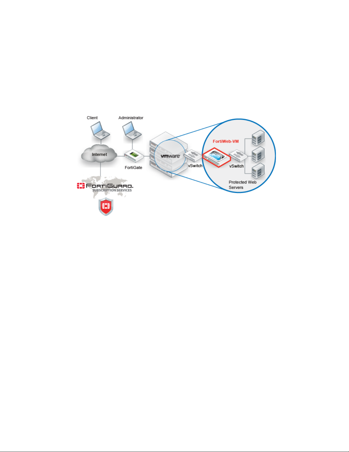
Figure 1: Basic topology
canning into a single device with no per-user pricing. Those
Scope
FortiWeb can be deployed in a one-arm topology, but is more commonly positioned inline to
intercept all incoming clients’ connections and redistribute them to your servers. FortiWeb has
TCP- and HTTP-specific firewalling capability. Because it is not designed to provide security to
non-HTTP applications, it should be deployed behind a firewall such as FortiGate that focuses
on security for other protocols that may be forwarded to your back-end servers, such as FTP
and SSH.
Once the appliance is deployed, you can configure FortiWeb via its web UI and CLI, from a web
ow
ser and terminal emulator on your management computer.
br
This document describes how to set up your FortiWeb appliance. For both the hardware and
virtual appliance versions of FortiWeb, it describes how to complete first-time system
deployment, including planning the network topology.
It also describes how to use the web user interface (web UI), and contains
port numbers, configuration limits, and supported standards.
This document assumes, if you have inst
you have already followed the instructions in the FortiWeb-VM Install Guide.
alled the virtual appliance version (FortiWeb-VM), that
lists of default utilized
Fortinet 14 FortiWeb 5.0 Patch 6 Administration Guide
Page 15

After completing “How to set up your FortiWeb” on page 60:
• You will have administrative access to the
web UI and/or CLI.
• You will have completed firmware updates, if any.
• The system time, DNS settings, administrator password, and network interfaces will be
configured.
• You will have set the operation mode.
• You will have configured basic logging.
• You will have created at least one server policy.
• You may have completed at least one phase of auto-learning to jump-start your
configuration.
Once that basic installation is complete, you can use the rest of this document to use the
web UI to:
• Update the FortiWeb appliance.
•
Rec
onfigure features.
• Use advanced features, such as anti-defacement.
• Diagnose problems.
This document does no
vide a reference for the command line interface (CLI). For that
t pro
information, see the FortiWeb CLI Reference.
This document is intended for administrators, not end users. If you a
re accessing a web site
protected by FortiWeb, please contact your system administrator.
Fortinet 15 FortiWeb 5.0 Patch 6 Administration Guide
Page 16

What’s new
The list below contains features new or changed since FortiWeb 5.0. For upgrade information,
see the Release Notes available with the firmware and “Updating the firmware” on page 77.
FortiWeb 5.0 Patch 6
• No ne
FortiWeb 5.0 Patch 5
• RADIUS vendor-specific attributes for access profiles — If your administrator accounts
FortiWeb 5.0 Patch 4
• Bulk edits for parameter validation rules — Rather than individually editing each rule, you
• Namibian time zone support — System time and date settings now support the Namibian
w features. Bug fixes only.
authenticate via a RADIUS query, you can assign their access profile using RFC 2548
Microsoft Vendor-specific RADIUS Attributes. See Access Profile in “Administrators” on
page 212 and “Configuring RADIUS queries” on page 233.
can now replace the Action, Trigger Policy, and/or Severity of multiple rules simultaneously.
See “Bulk changes to input validation rules” on page 428.
time zone. See “Setting the system time & date” on page 91.
FortiWeb 5.0 Patch 3
• No new features. Bug fixes only.
FortiWeb 5.0 Patch 2
• Hidden fields protection for HTTPS — You can now use the Fetch URL dialog in the GUI to
help you tamper-proof hidden inputs in HTTPS requests. See “Preventing tampering with
hidden inputs” on page 430.
• Indicating original service to back-end servers— When offloading SSL/TLS, you can now
use an HTTP X-header to indicate to back-end web servers that the original client’s request
was, in fact, encrypted. See “Indicating to back-end web servers that the client’s request
was HTTPS” on page 269.
• More Microsoft file types for file upload restrictions — There are now signatures
specifically for Microsoft Office Open XML file types such as .docx. See “Limiting file
uploads” on page 451.
• Per CPU SNMP queries— You can now monitor the usage of each CPU in multi-CPU
appliances. See “MIB support” on page 586.
• NMI and COMlog support — FortiWeb 3000D, 3000DFsx, and 4000D models that have
NMI buttons now have firmware support. This can be useful for carriers that require
extensive debugging capabilities. See your model’s QuickStart Guide and the FortiWeb NMI
& COMlog Technical Note.
• RAM-only traffic log support — To reduce wear and tear on your hard disks when you
require traffic logs, you can now disable hard disk storage of traffic logs and use RAM only.
See the FortiWeb CLI Reference.
Fortinet 16 FortiWeb 5.0 Patch 6 Administration Guide
Page 17

FortiWeb 5.0 Patch 1
• Site publishing— You can now easily publish Microsoft Outlook Web Access (OWA),
SharePoint, Lync and other web applications. FortiWeb streamlines access to the
applications by providing offloaded authentication with optional single sign-on (SSO)
functionality. See Site Publish and “Single sign-on (SSO)” on page 243.
• “Alert Only” action for individual signatures — To provide better flexibility, you can now
choose an Alert Only action for individual attack signatures. When configuring a protection
profile, save it, then return to it and click the Advanced Mode button. Select a signature
category from the menu. When individual signatures appear in the pane on the right, click
the signature’s row to select it, then mark the Alert Only check box in the Signature tab. See
“Configuring action overrides or exceptions to data leak & attack detection signatures” on
page 398.
• Attack signature filters — In the Advanced mode while configuring attack signatures, in the
bottom of the navigation tree on the left, new categories have been added that display
individual signatures that have been disabled, or whose Alert Only check box is marked.
Previously, the Search item in the tree only enabled you to search for signature IDs. See
“Finding signatures that are disabled or “Alert Only”” on page 401.
• Custom global white list objects— You can now add your own URLs, parameters, and
cookies that you don’t want FortiWeb to inspect. Previously, you could only white list
predefined objects. See “Configuring the global object white list” on page 464.
• Advanced/combination access control rule enhancement— When configuring HTTP
header conditions for combination access control rules, regular expressions are now
supported. See “Combination access control & rate limiting” on page 325.
• Performance enhancements— Memory utilization and other performance enhancements
have been made. For example, the antivirus database now loads into memory only while
antivirus is enabled in a policy.
• New geo-to-IP database format supported
FortiWeb 5.0
Back up all parts of the configuration and data before updating the firmware to FortiWeb 5.0.
Some backup types do not include the full configuration. For full backup instructions, see
“Backups” on page 206.
FortiWeb 5.0 configuration files are not compatible with previous firmware versions. Many
fundamental changes have been made to its configuration file structure. If you later decide to
downgrade to FortiWeb 4.4.7 or earlier, your FortiWeb appliance will lose its configuration.
To restore the configuration, you will need a backup that is compatible with the older
firmware.
• FortiWeb 3000D, 3000DFsx, and 4000D support — All three models support SSL/TLS
acceleration with CP8 ASIC chips and have bypass/fail-to-wire port pairs. For hardware
details, see your model’s QuickStart Guide and “Fail-to-wire for power loss/reboots” on
page 520. For specifications of maximum supported objects, see “Appendix B: Maximum
configuration values” on page 669.
• Password recovery — If you have forgotten the password, but have physical access to your
FortiWeb, you can now reset the password for the admin administrator account. See
“Resetting passwords” on page 656.
Fortinet 17 FortiWeb 5.0 Patch 6 Administration Guide
Page 18

• IPv6 support— If FortiWeb is operating in reverse proxy mode, the following features now
support IPv6-to-IPv6 forwarding, as well as NAT64, to support environments where legacy
back-end equipment only supports IPv4.
• IP/Netmask for all types of network interfaces, DNS settings, and Gateway and
Destination IP/Mask for IP-layer static routes
• Virtual Server/V-zone
• Physical Server/Domain Server/Server Farm
• Server Health Check
• Protected Servers
• Session Management
• Cookie Poisoning Detection
• Signatures
• Custom Access
• Parameter Validation
• Hidden Fields Protection
• File Upload Restriction
• HTTP Protocol Constraints
• Brute Force Login
• URL Access
• Page Access (page order)
• Start Pages
• Allow Method
• IP List (manual, individual IP blacklisting/whitelisting)
• File Compress/File Uncompress
• Auto-learning
• Vulnerability scans
• Global white list objects
• Chunk decoding
• FortiGuard server IP overrides
These are not yet supported:
If a policy has any virtual servers, server farms, physical servers, or domain servers with IPv6
addresses, it will not apply these features, even if they are selected.
Fortinet 18 FortiWeb 5.0 Patch 6 Administration Guide
Page 19

• X-Forwarded-For
• Shared IP
• Policy bypasses for known search engines
• Geo IP
• DoS Protection
• IP Reputation
• URL Rewriting (also redirection)
• HTTP Authentication and LDAP, RADIUS, and NTLM profiles
• Data Analytics
• Log-based reports
• Alert email
• Syslog and FortiAnalyzer IP addresses
•NTP
• FTP immediate/scheduled
• OCSP/SCEP
•Anti-defacement
• HA/Configuration sync
• exec restore
• exec backup
• exec traceroute
• exec telnet
• Challenge action for application-level anti-DoS — Rather than simply blocking all clients
that exceed your rate limit or trigger other DoS sensors, you can now choose to test the
client first — to return a web page that uses a script to assess whether the client is a web
browser or an automated tool favored by attackers. In this way, you can allow higher rate
limits for people than automated tools. See “Limiting the total HTTP request rate from an IP”
on page 339 and “Preventing an HTTP request flood” on page 347.
• Search engine access improved — You can now allow known search engines such as
Google, Yahoo!, Baidu and Bing to be exempt from DoS sensors, brute force login sensors,
HTTP protocol constraints, and combination rate & access control (called “advanced
protection” and “custom policies” in the web UI). See Allow Known Search Engines in
“Configuring a protection profile for inline topologies” on page 468 or “Configuring a
protection profile for an out-of-band topology or asynchronous mode of operation” on
page 477.
• Robot control simplified — Control of known malicious automated tools has been
simplified, and custom robot definitions removed. See Bad Robot in “Blocking known
attacks & data leaks” on page 387.
• Robot monitoring report — To monitor search engines that may be abusing access, you
can monitor throughput and transactions per second for each crawler from your GUI’s
reports area. See “Bot analysis” on page 605.
• Dynamic rate threshold in Real Time Monitor widget — The Policy Summary widget has
been renamed, and now scales its graph dynamically to best show you differences based
upon your normal levels of traffic. See “Real Time Monitor widget” on page 537.
• HTTP status code customization — To prevent WAF fingerprinting that can be a precursor
for evasive APT attackers, you can now modify the return codes such as 200 OK that
Fortinet 19 FortiWeb 5.0 Patch 6 Administration Guide
Page 20

FortiWeb returns to clients when blocking violation traffic. See Error Page Return Code in
“Configuring a server policy” on page 483.
• Seamless FortiWeb-VM vCPU license upgrades— Now you can increase the capacity of
FortiWeb-VM to 2, 4, or 8 vCPUs without first invalidating the license. Previously, a new
license could be uploaded only while the current license was invalid, thereby temporarily
interrupting service. See the FortiWeb-VM Install Guide.
• Maximum physical servers increased — FortiWeb now supports up to 255 physical
servers. Previously only 128 were possible. See “Defining your web server by its IP address”
on page 251.
• Maximum input validation rules increased — FortiWeb now supports up to 1,024
parameters in the URL validation rule. See “Validating parameters (“input rules”)” on
page 421.
• Erasure without alerts — A very high volume of attack logs, alert email, and that can be
generated while blocking information disclosure when many protected web servers are
misconfigured. To prevent this and allow you to focus on severe attacks, you can now
choose to erase server information such as X-Powered-By: without generating any log
messages. See Action in “Blocking known attacks & data leaks” on page 387.
• Support for subnets in URL access rules & manual blacklists/white lists— When
specifying which source IP addresses are allowed to access your web apps, you can now
specify multiple IP addresses by entering a subnet, rather than creating many individual
rules. See “Restricting access to specific URLs” on page 321 and “Blacklisting & whitelisting
clients individually by source IP” on page 335.
• RADIUS realm support— RADIUS accounts on servers that require the realm (e.g.
admin@example.com or user@example.com) are now supported. No change to the
FortiWeb configuration is required for end-user accounts. For administrators, modify the
Administrator setting to include the realm name (e.g. @example.com).
• Fail-to-wire during reboot/shutdown— Previously, fail-to-wire only engaged during
unexpected power loss, without a graceful shutdown. See “Fail-to-wire for power
loss/reboots” on page 520.
• Threshold for shared IPs configurable — Previously, shared IP analysis was not
configurable. See “Shared IP” on page 522.
• Reports like FortiGate 5.0 — Reports have been updated, and now reflect the same styles
also found in FortiGate 5.0 firewalls. See “Reports” on page 586.
• Debugging commands on HA standby — You can now use the active FortiWeb HA
appliance’s CLI to send diagnose debug commands through the HA link to the standby.
Previously, you could only connect to standby appliances through the local console, or by
triggering a failover so that the standby became active — network connectivity was only
possible with the active appliance. See the FortiWeb CLI Reference.
• XML protection profiles removed
rs should now use the Illegal XML Format setting (see “Configuring a protection
stome
cu
— For protection against XML-related attacks,
profile for inline topologies” on page 468 or “Configuring a protection profile for an
out-of-band topology or asynchronous mode of operation” on page 477). Legacy
configuration data related to XML protection profiles from FortiWeb 4.0 MR4 Patch 6 or
previous versions of the firmware will be deleted during upgrade.
If your back-end web servers require extensive protection for a vulnerable XML parser, you
rd
should add 3
-party XML protection to your security architecture. Unlike XML protection
profiles in previous versions of FortiWeb, Illegal XML Format does not scan for conformity
with the document object model (DOM)/DTD/W3C Schema, recursive payloads, Schema
poisoning, or other advanced XML attacks. Failure to provide adequate XML protection
could allow attackers to penetrate your network.
Fortinet 20 FortiWeb 5.0 Patch 6 Administration Guide
Page 21

• Static routes moved— It is now located under the System > Network menu. See “Adding a
gateway” on page 125.
• FortiGuard updates moved— It is now located under the System > Config menu, similar to
FortiGate 5.0. Configuration of the antivirus database has also moved. See “Choosing the
virus signature database & decompression buffer” on page 138.
• LDAP, RADIUS, NTLM profiles moved— They are now located under the new User >
Remote Server menu to make obvious the dichotomy versus local authentication. See
“Grouping remote authentication queries for administrators” on page 218 and “Configuring
queries for remote end-user accounts” on page 228.
• Anti-defacement moved— It is now located under the Web Protection menu. See
“Anti-defacement” on page 498.
Fortinet 21 FortiWeb 5.0 Patch 6 Administration Guide
Page 22

Key concepts
This chapter defines basic FortiWeb concepts and terms.
If you are new to FortiWeb, or new to security, this chapter can help you to quickly understand.
See also
• Appliance vs. VMware
Workflow
Begin with “How to set up your FortiWeb” on page 60 for your initial deployment. These
instructions will guide you to the point where you have a simple, verifiably working installation.
Ongoing use is located in the chapters after “How to set up your FortiWeb”. Once you
have
successfully deployed, ongoing use involves:
• Backups
• Updates
•
Configuring optional features
• Adjusting policies if:
• New attack signatures become available
• Requirements change
• Fine-tuning performance
• Periodic web vulnerability scans if required by your compliance regime
• Monitoring for defacement or focused, innovative attack attempts from advanced persistent
threats (APTs)
• Monitoring for accidentally blacklisted client IPs
• Using data analytics to show traffic patterns
Fortinet 22 FortiWeb 5.0 Patch 6 Administration Guide
Page 23
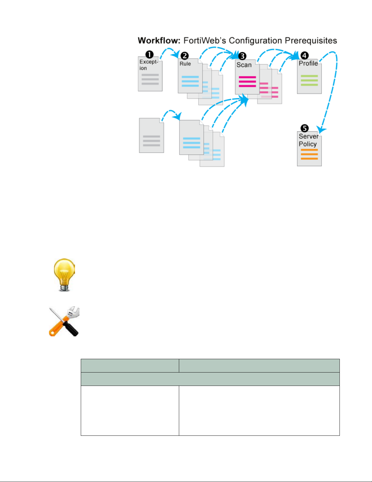
Except for features
independent of
policies such as
ti-defacement,
an
most features are
configured before
policies. Policies
link protection
components
together and apply
them. As such,
policies usually
should be
configured last,
not first.
Sequence of scans
FortiWeb appliances apply protection rules and perform protection profile scans in the following
order of execution, which varies by whether you have applied a web protection profile. To
understand the scan sequence, read from the top of the table (the first scan/action) towards the
bottom (the last scan/action). Disabled scans are skipped.
To improve performance, block attackers using the earliest possible technique in the execution
sequence and/or the least memory-consuming technique.
The blocking style varies by feature and configuration. For example, when detecting cookie
poisoning, instead of resetting the TCP connection or blocking the HTTP request, you could log
and remove the offending cookie. For details, see each specific feature.
Tab l e 1 : Execution sequence (web protection profile)
Scan/action Involves
Request from client to server
TCP Connection Number Limit
(TCP Flood Prevention)
Sour
ce IP address of the client (depending on your
configura
proxies, clients, & X-headers” on page 266) this could be
derived from either the SRC f
HTTP header such as X-Forwarded-For: or
X-Real-IP:)
tion of X-header rules (see “Defining your
ield in t
he IP header, or an
Fortinet 23 FortiWeb 5.0 Patch 6 Administration Guide
Page 24

Tab l e 1 : Execution sequence (web protection profile)
Scan/action Involves
Block Period Source IP address of the client (depending on your
configuration of X-header rules (see “Defining your
proxies, clients, & X-headers” on page 266) this could be
derived from either the SRC f
ield in t
he IP header, or an
HTTP header such as X-Forwarded-For: or
X-Real-IP:)
IP List *
urce IP address of the client in the IP layer
So
(individual client IP black list or
white list)
Add X-Forwarded-For:
Source IP address of the client in the HTTP layer
Add X-Real-IP:
IP Reputation Source IP address of the client (depending on your
configura
tion of X-header rules (see “Defining your
proxies, clients, & X-headers” on page 266) this could be
derived from either the SRC f
ield in t
he IP header, or an
HTTP header such as X-Forwarded-For: or
X-Real-IP:)
Allow Known Search Engines Source IP address of the client in the IP layer
Geo IP Source IP address of the client in the IP layer
Host
Host:
(allowed/protected host name)
Allow Method • Host:
URL in HTTP
•
header
• Request method in HTTP header
HTTP Request Limit/sec • Cookie:
•
ssion state
Se
• Responses from the JavaScript browser tests, if any
Session Management • Cookie:
•
ssion state
Se
TCP Connection Number Limit
(Malicious IP)
Sour
ce IP address of the client (depending on your
configura
tion of X-header rules (see “Defining your
proxies, clients, & X-headers” on page 266) this could be
derived from either the SRC f
ield in t
he IP header, or an
HTTP header such as X-Forwarded-For: or
X-Real-IP:)
HTTP Request Limit/sec
(HTTP Flood Prevention)
• Cookie:
• Session state
• URL in the HTTP header
Fortinet 24 FortiWeb 5.0 Patch 6 Administration Guide
Page 25

Tab l e 1 : Execution sequence (web protection profile)
Scan/action Involves
HTTP Request Limit/sec
(Standalone IP)
or
HTTP Request Limit/sec (Shared
IP)
(HTTP Access Limit)
• ID field of the IP header
• Source IP address of the client (depending on your
configuration of X-header rules (see “Defining your
proxies, clients, & X-headers” on page 266) this could
be derived from either the SRC field in the IP header, or
an HTTP header such as X-Forwarded-For: or
X-Real-IP:)
HTTP Authentication Authorization:
Global White List • Cookie: cookiese
L if /favicon.ico, AJAX URL parameters such as
•UR
ssion1
__LASTFOCUS, and others as updated by the
FortiGuard Security Service
URL Access • Host:
• URL in HTTP
header
• Source IP of the client in the IP header
Brute Force Login • Source IP address of the client (depending on your
co
nfigura
tion of X-header rules (see “Defining your
proxies, clients, & X-headers” on page 266) this could
be derived from either the SRC field in the IP header, or
an HTTP header such as X-Forwarded-For: or
X-Real-IP:)
• URL in the HTTP header
HTTP Protocol Constraints • Content-Length:
Pa
rameter length
•
• Body length
• Header length
• Header line length
•Count of Range: header lines
• Count of cookies
Cookie Poisoning Detection Cookie:
Start Pages • Host:
•
URL in HTTP
header
• Session state
Page Access
(page order)
• Host:
•
URL in HTTP
header
• Session state
File Upload Restriction • Content-Length:
• Content-Type:
in PUT an
d POST
requests
Fortinet 25 FortiWeb 5.0 Patch 6 Administration Guide
Page 26

Tab l e 1 : Execution sequence (web protection profile)
Scan/action Involves
Troj an s HTTP body
Bad Robot User-Agent:
Parameter Validation • Host:
• URL
in the HTTP header
• Name, data type, and length of <input> tags except
<input type="hidden">
Cross Site Scripting, SQL
Injection, Generic Attacks
(attack signatures)
• Cookie:
•
rameters in the URL in the HTTP header, or in the
Pa
HTTP body (depending on the HTTP method) for
<input> tags except <input type="hidden">
• XML content in the HTTP body (if Enable XML Protocol
Detection is enabled)
Hidden Fields Protection • Host:
• URL
in the HTTP header
• Name, data type, and length of
<input type="hidden">
X-Forwarded-For X-Forwarded-For: in HT
URL Rewriting
(rewriting & redirects)
• Host:
• Referer:
TP h
eader
• Location:
•
URL in HTTP
header
• HTTP body
Auto-learning Any of the other features included by the auto-learning
pr
ofile
Data Analytics • S
ource IP address of the client
• URL
in the HTTP header
• Results from other scans
Client Certificate Forwarding
Client’s personal certificate, if any, supplied during the
SSL/TLS handshake
Reply from server to client
Information Disclosure Server-identifying custom HTTP headers such as
Server: and X-Powered-By:
edit Card Detection Credit card number in the body, and, if configured, Credit
Cr
Card Detection Threshold
File Uncompress Content-Encoding:
Fortinet 26 FortiWeb 5.0 Patch 6 Administration Guide
Page 27

Tab l e 1 : Execution sequence (web protection profile)
Scan/action Involves
URL Rewriting
(re
writing)
File Compress Accept-Encoding:
* If a source IP is white listed, su
Solutions for specific web attacks
The types of attacks that web servers are vulnerable to are varied, and evolve as attackers try
new strategies.
FortiWeb appliances offer numerous configurable features for preventing web-related attacks,
includin
Early in your deployment of FortiWeb, configure and run web vulnerability scans to detect the
most common attack vulnerabilities. You can use this to discover attacks that you may be
vulnerable to. For more information, see
g denial-of-service (DoS) assaults, brute-force logins, data theft, and more.
• Host:
• Referer:
• Location:
•
URL in HTTP
• HTTP body
bsequent checks will be skipped.
“Vulnerability scans” on page 505.
header
HTTP/HTTPS threats
Servers are increasingly being targeted by exploits at the application layer or higher. These
attacks use HTTP/HTTPS and aim to compromise the target web server, either to steal
information, deface it, or to post malicious files on a trusted site to further exploit visitors to the
site, using the web server to create botnets.
Among its many threat management features, FortiWeb’s fends off attacks that use cross-site
scripting
standards for:
• credit-card data, such as PCI DSS 6.6
• per
Ta bl e 2 lists several HTTP-related threats and describes how FortiWeb appliances protect
servers from them. FortiWeb can also protect against threats at higher layers (HTML, Flash or
XML applications).
, state-based, and various injection attacks. This helps you comply with protection
sonally identifiable information, such as HIPAA
Fortinet 27 FortiWeb 5.0 Patch 6 Administration Guide
Page 28

Tab l e 2 : Web-related threats
Attack
Description Protection FortiWeb Solution
Technique
Adobe Flash
y
binar
(AMF)
protocol
Attackers attempt XSS, SQL
injection
or other common
exploits through an Adobe Flash
client.
attacks
Botnet Utilizes zombies previously
exploited or infected (or
willingly
participating), distributed usually
glo
bally, to simultaneously
overwhelm the target when
directed by the command and
control server(s).
Browser
it
Explo
Against
SSL/TLS
(BEAST)
n-in-the-middle attack
A ma
ere an eavesdropper exploits
wh
reused initialization vectors in
older TLS 1.0 implementations of
CBC-based encryption ciphers
such as AES and 3DES.
Decode and scan Flash
tion message format
ac
(AMF) binary data for
matches with attack
signatures.
Decode and scan Flash
tion message format
ac
(AMF) binary data for
matches with attack
signatures.
• Use TLS 1.1 or
reater, or
g
• Use ciphers that do
not involve CBC,
such as stream
ciphers, or
• Use CBC only with
correct initialization
vector (IV)
implementations
Enable AMF3
Protocol Detection
IP Reputation
Prioritize RC4
Cipher Suite
Brute force
in
attack
log
An attacker attempts to gain
authorization by repeatedly trying
ID and password combinations
until one works.
Clickjacking Code such as <IFRAME> HT
tags
superimposes buttons or
other DOM/inputs of the
attacker’s choice over a normal
form, causing the victim to
unwittingly provide data such as
bank or login credentials to the
attacker’s server instead of the
legitimate web server when the
victim clicks to submit the form.
Cookie
ta
mper
ing
Attackers alter cookies originally
established by the server to inject
overflows, shell code, and other
attacks, or to commit identity
fraud, hijacking the HTTP
sessions of other clients.
Require strong
words for users,
pass
and throttle login
attempts.
ML
Scan for illegal inputs to
event the initial
pr
injection, then apply
rewrites to scrub any
web pages that have
already been affected.
Validate cookies
eturned by the client to
r
ensure that they have
not been altered from
the previous response
from the web server for
that HTTP session.
Brute Force Login
natures
• Sig
• Parameter
Validation
• Hidden Fields
Protection
• URL Rewriting
Cookie Poisoning
Detection
Fortinet 28 FortiWeb 5.0 Patch 6 Administration Guide
Page 29

Tab l e 2 : Web-related threats
Attack
Technique
Credit card
theft
Cross-site
qu
est
re
forgery
(CSRF)
Cross-site
ripting
sc
(XSS)
Denial of
rvice
se
(DoS)
Description Protection FortiWeb Solution
Attackers read users’ credit card
information in replies from a web
server.
Detect and sanitize
credit card data leaks.
Helps you comply with
credit car
d protection
Credit Card
Detection
standards, such as PCI
DSS 6.6.
A script causes a browser to
cess a web site on which the
ac
browser has already been
authenticated, giving a third party
access to a user’s session on that
Enforce web application
iness logic to prevent
bus
access to URLs from the
same IP but different
client.
Page Access
site. Classic examples include
hijacking other peoples’ sessions
at coffee shops or Internet cafés.
ckers cause a browser to
Atta
execute a client-side script,
allowing them to bypass security.
An
attacker uses one or more
techniques to flood a host with
HTTP requests, TCP
connections, and/or TCP SYN
signals. These use up available
sockets and consume resources
on the server, and can lead to a
temporary but complete loss of
service for legitimate users.
Content filtering, cookie
security, disable
client-side scripts.
Watch for a multitude of
P and HTTP requests
TC
arriving in a short time
frame, especially from a
single source, and close
suspicious connections.
Detect increased SYN
signals, close half-open
connections before
Cross Site
Scripting
DoS Protection
resources are
exhausted.
HTTP
ade
r
he
overflow
Attackers use specially crafted
HTTP/HTTPS requests to target
web server vulnerabilities (such
Limit the length of HTTP
otocol header fields,
pr
bodies, and parameters.
HTTP Protocol
Constraints
as a buffer overflow) to execute
malicious code, escalating to
administrator privileges.
Fortinet 29 FortiWeb 5.0 Patch 6 Administration Guide
Page 30

Tab l e 2 : Web-related threats
Attack
Technique
Local file
inclusion
(LFI)
Description Protection FortiWeb Solution
LFI is a type of injection attack.
However, unlike SQL injection
Block directory traversal
commands.
Generic Attacks
attacks, a database is not always
involved. In an LFI, a client
includes directory traversal
commands (such as ../../for
web servers on Linux, Apple Mac
OS X, or Unix distributions) when
submitting input. This causes
vulnerable web servers to use
one of the computer’s own files
(or a file previously installed via
another attack mechanism) to
either execute it or be included in
its own web pages.
This could be used for many
es, including direct
urpos
p
attacks of other servers,
installation of malware, and data
theft of /etc/passwd, display of
database query caches, creation
of administrator accounts, and
use of any other files on the
server’s file system.
Malicious
bo
ts
ro
Many platforms have been
able to these types of
ulner
v
attacks, including Microsoft .NET
and Joomla.
Misbehaving web crawlers ignore
the robots.txt file, and
consume server resources and
bandwidth on a site.
Ban bad robots by
ce IP or
sour
User-Agent: field, as
well as rate limiting
clients that fail a test that
detects web browsers
Real Browser
Enforcement
Exception
Fortinet 30 FortiWeb 5.0 Patch 6 Administration Guide
Page 31

Tab l e 2 : Web-related threats
Attack
Technique
Remote file
inclusion
(RFI)
Description Protection FortiWeb Solution
RFI is a type of injection attack.
However, unlike SQL injection
attacks, a database is not always
Prevent inclusion of
rences to files on
refe
other web servers.
Generic Attacks
involved. In an RFI, a client
includes a URL to a file on a
remote host, such as source
code or scripts, when submitting
input. This causes vulnerable
web servers to either execute it
or include it in its own web
pages.
• If code is executed, this could
us
ed for many purposes,
be
including direct attacks of
other servers, installation of
malware, and data theft.
• If code is included into the
local file system, this could be
used to cause other,
unsuspecting clients who use
those web pages to commit
distributed XSS attacks.
Server
information
e
leakag
Famously, this was used in
rga
nized attacks by Lulzsec.
o
Attacks often involve PHP web
applications, but can be written
for others.
A web server reveals details
(such as its OS, server software
and installed modules) in
responses or error messages. An
attacker can leverage this
fingerprint to craft exploits for a
specific system or configuration.
Configure server
softwar
e to minimize
information leakage.
• Information
Disclosure
•To hide
application
structure and
servlet names,
Rewriting &
redirecting
Fortinet 31 FortiWeb 5.0 Patch 6 Administration Guide
Page 32

Tab l e 2 : Web-related threats
Attack
Technique
SQL
injection
Malformed
XML
Description Protection FortiWeb Solution
The web application inadvertently
accept
These are executed directly
against the database for
unauthorized disclosure and
modification of data.
To exploit XML parser or data
modeling
client sends incorrectly formed
tags and attributes.
s SQL queries as input.
bugs on the server, the
Rely on key word
arches, restrictive
se
context-sensitive
filtering and data
sanitization techniques.
Validate XML formatting
r closed tags and other
fo
basic language
requirements.
ameter
• Par
Validation
• Hidden Fields
Protection
• SQL Injection
Illegal XML Format
Caution: Unlike
pro
XML
profiles in previous
versions of
FortiWeb, Illegal
XML Format does
not ch
con
object model or
recursive
payloads.
tection
eck for
formity with the
DoS attacks
A denial of service (DoS) attack or distributed denial-of-service attack (DDoS attack) is an
attempt to overwhelm a web server/site, making its resources unavailable to its intended users.
DoS assaults involve opening vast numbers of sessions/connections at various OSI layers and
keeping them open as long as possible to overwhelm a server by consuming its available
sockets. Most DoS attacks use automated tools (not browsers) on one or more hosts to
generate the harmful flood of requests to a web server.
A DoS assault on its own is not true penetration. It is designed to silence its target, not for theft.
It is
in lost sales and a tarnished reputation. DoS can also be used as a diversion tactic while a true
exploit is being perpetrated.
The advanced DoS prevention features of FortiWeb are designed to prevent DoS techniques,
such a
DoS protection policy that includes all of FortiWeb’s DoS defense mechanisms, and block traffic
that appea
c
ensorship, not robbery. In any event, a successful DoS attack can be costly to a company
s those examples listed in Ta bl e 3, from succeeding. For best results, consider creating a
rs to originate from another country, but could actually be anonymized by VPN or Tor.
Fortinet 32 FortiWeb 5.0 Patch 6 Administration Guide
Page 33

For more information on policy creation, see “DoS prevention” on page 338 and “Blacklisting
source IPs with poor reputation” on page 329.
Tab l e 3 : DoS-related threats
Attack
Description FortiWeb Solution
Technique
Botnet Utilizes zombies previously exploited or
infected (or willingly participating),
distributed
usually globally, to simultaneously overwhelm
the target when directed by the command and
control server(s). Well-known examples include
LOIC, HOIC, and Zeus.
Low-rate DoS Exploits TCP’s retransmission time-out (RTO)
by se
nding sho
rt-duration, high-volume bursts
repeated periodically at slower RTO
time-scales. This causes a TCP flow to
repeatedly enter a RTO state and significantly
reduces TCP throughput.
Slow POST
attack
Sends multiple HTTP POST
legitimate Content-Length: field. This tells
requests with a
the web server how much data to expect. Each
POST message body is then transmitted at an
unusually slow speed to keep the connection
from timing out, and thereby consuming
sockets.
IP Reputation
P Connection Number
• TC
Limit (TCP flood
prevention)
• HTTP Request Limit/sec
(HTTP flood prevention)
• TCP Connection Number
Limit (malicious IP
prevention)
• URL Access
• Allow
Method
Fortinet 33 FortiWeb 5.0 Patch 6 Administration Guide
Page 34

Tab l e 3 : DoS-related threats
Attack
Technique
Slowloris Slowly but steadily consumes all available
SYN flood Sends a stream of TCP SYN packet
Description FortiWeb Solution
so
cket
s by sending partial HTTP requests sent
at regular intervals. Each HTTP header is never
finished by a new line (/r/n) according to the
specification, and therefore the server waits for
the client to finish, keeping its socket open.
This slowly consumes all sockets on a web
server without a noticeable spike on new
TCP/IP connections or bandwidth.
Not all web servers are vulnerable, and
susceptibility
Apache configurations may be more vulnerable
than a server like nginx that is designed for
high concurrency.
target server acknowledges each SYN and
waits for a response (ACK). Rather than
respond, the attacker sends more SYN
packets, leaving each connection half-open,
not fully formed, so that it may not register on
systems that only monitor fully formed
connections. Since each half-formed
connection requires RAM to remember this
state while awaiting buildup/tear-down, many
SYN signals eventually consume available RAM
or sockets.
can vary by configuration. De
s. The
Header Length
Number of Header Lines In
Request
Real Browser Enforcement
Persistent Server Sessions
fault
Syn Cookie
HTTP sessions & security
The HTTP 1.1 protocol itself is stateless (i.e., has no inherent support for persistent sessions).
Ye t many web applications add sessions to become stateful.
Why?
What is a session? What is statefulness?
How do they impact security on the web?
Sessions are a correlation of requests for individual web pages/data (“hits”) into a sense of an
ov
erall “v
They typically consist of a session ID coupled with its data indicating current state.
Classic examples include logins, showing previously viewed items, and shopping carts.
The reason why HTTP applications must add sessions is re
software often changes how it appears or acts based upon:
• Input you supply (e.g. a mouse click or a data file)
• System events (e.g. time
• Current state (i.e. the product of previous events — history)
Fortinet 34 FortiWeb 5.0 Patch 6 Administration Guide
isit” for a client during a time span, but also retain some memory between events.
lated to how software works:
or availability of a network connection)
Page 35

At each time, some inputs/actions are known to be valid and possible, while others are not.
Without memory of history to define the current context, which actions are valid and
possible, and therefore how it should function, cannot be known.
When software cannot function without memory, it is statef
ul. Many important features —
denying access if a person is not currently logged in, for example, or shipping what has been
added to
a shopping cart — are stateful, and therefore can’t be supported by purely stateless
HTTP according to the original RFC. Such features require that web apps augment the HTTP
protocol by adding a notion of session memory via:
• Cookies per RFC 2965
• Hidden inputs
Server-side sessions
•
• Other means (see “Authentication styles” on page 221)
Because memory is an accumulation of input,
sessions
have security implications.
• Can a different client easily forge another’s session?
• Ar
e session IDs reused in encrypt form data, thereby weakening the encryption?
• Are session histories used to check for invalid next URLs or inputs (state transitions)?
When sessions are not protected to prevent misuse, software can be used in unexpected
wa
ys by at
tackers.
For example, let’s say there is a vending machine. You must insert money first. If you:
• insert a paper clip instead of a coin
• pr
ess the button for a snack before you have inserted enough money
• press the button to return your money before you have inserted any money
the machine will do nothing. The machine is
designed so that i
t must be in the state where it
has received enough money before it will dispense the snack (or return your change).
Figure 2: State transitions in a vending machine
If the vending machine had no notion of states, it would dispense free snacks or change —
regardless of whether it had received any money.
While free snacks might make some hungry people happy, it is not the intended behavior. We
would sa
y that the vending machine is broken.
Fortinet 35 FortiWeb 5.0 Patch 6 Administration Guide
Page 36

Figure 3: Invalid state transition in a vending machine
Similar to the working vending machine, in the TCP protocol, a connection cannot be
acknowledged (ACK) or data sent (PSH) before the connection has been initiated (SYN). There is
a definite order to valid operations, based upon the operation that preceded it. If a connection is
not already established — not in a state to receive data — then the receiver will disregard it.
Similar to the broken vendin
g machine, the naked HTTP protocol has no idea what the previous
HTTP request was, and therefore no way to predict what the next one might be. Nothing is
required to persist from one request to the next. While this was adequate at the time when
HTTP was initially designed, when it purely needed to retrieve static text or HTML documents,
as the World Wide Web evolved, this was no longer enough. Static pages evolved into dynamic
CGI-generated and JavaScripted pages. Dynamic pages use programs to change the page.
Scripted pages eventually evolved to fully-fledged multimedia web applications with their own
client-server architecture. As pages became software in their own right, a need for sessions
arose.
When a web application has its own native authentication, the session may correspond directly
s authentication logs — server-side sessions may start with a login and end with a
h it
wit
logout/session timeout. Within each session, there are contexts that the software can use to
determine which operations make sense. For example, for each live session, a web application
might remember:
• Who is the client? What is his/her user name?
• Where
is the client?
• What pages has the client already seen today?
• What forms has the client already completed?
However, sessions alone are not
ou
gh to ensure that a client’s requested operations make
en
sense. The client’s next page request in the session could break the web application’s logic
unless requests are restricted to valid ones.
For example, a web application session may remember that a client has authenticated. But
unless it also know
s what pages that client is authorized to use, there might be nothing to
prevent that person from ignoring the links on the current web page and entering a
non-authorized URL into their web browser to steal secret information.
Fortinet 36 FortiWeb 5.0 Patch 6 Administration Guide
Page 37

Figure 4: Attack bypassing logical state transitions in a session
If they do not enforce valid state transitions and guard session IDs and cookies from fraud
(including sidejacking attacks made famous by Firesheep) or cookie poisoning,
web applications become vulnerable to state transition-based attacks — attacks where pages
equested out of the expected order, by a different client, or where inputs used for the next
are r
page are not as expected. While many web applications reflect business logic in order to
function, not all applications validate state transitions to enforce application logic. Other web
applications do attempt to enforce the software’s logic, but do not do so effectively. In other
cases, the state enforcement itself has bugs. These are common causes of security
vulnerabilities.
Similar to plain HTTP, SSL/TLS also keeps track of what steps the client has completed in
encryption negotiation, and what the agreed keys and algorithms are. These HTTPS sessions
are separate from, and usually in addition to, HTTP sessions. Attacks on SSL/TLS sessions are
also possible, such as the SPDY protocol/Deflate compression-related CRIME attack.
FortiWeb sessions vs. web application sessions
FortiWeb can add its own sessions to enforce the logic of your web applications,
thereby hardening their security, even without applying patches.
Your web application may have its own sessions data — one or more. These are not the same
as FortiWeb sessions, unless FortiWeb is operating in a mode that does not support FortiWeb
session cookies, and therefore uses your web application’s own sessions as a cue (see
Key Word).
FortiWeb does not r
applications, such as the JSESSIONID parameter common in Java server pages (JSP), or web
applications’ session cookies such as the TWIKISID cookie for Twiki wikis.
However, it can protect those sessions. To configure protection for your web application’s own
sessions,
Fields Protection.
see options such as Cookie Poisoning Detection, Parameter Validation, and Hidden
eplace or duplicate sessions that may already be implemented in your web
Session
For example, to reinforce authentication logic, you might want to require that a client’s first
HTTP r
has authenticated, because out-of-order requests could be an attempt to bypass the web
application’s authentication mechanism.
Fortinet 37 FortiWeb 5.0 Patch 6 Administration Guide
equest always be a login page. All other web pages should be inaccessible until a client
Page 38

How can FortiWeb know if a request is the client’s first HTTP request? If FortiWeb were to treat
each request independently, without knowledge of anything previous, it would not be able to
remember the authentication request, and therefore could not enforce page order.
To fill this need for context, enable Session Management. When enabled:
1. For the first HTTP/HTTPS request from a client, FortiWeb embeds a cookie in the response’s
Set-Cookie: field in the HTTP header. It is named cookiesession1. (FortiWeb does not
use source IP addresses and timestamps alone for sessions: NAT can cloak multiple clients;
clocks can be altered.)
If you have configured rules such as start page rules that are enforced when a page request
is the first in a session, FortiWeb can enforce them at this point.
2. Later requests from the same client must include this same cookie in the Cookie: field to
be regarded as part of the same session. (Otherwise, the request will be regarded as
session-initiating, and return to step 1.)
Figure 5: Attack blocked via a start page or page order rule with session management
Once a request’s session is identified by the session ID in this cookie (e.g.
K8BXT3TNYUM710UEGWC8IQBTPX9PRWHB), FortiWeb can perform any configured tracking
or enforcement actions that are based upon the requests that it remembers for that session
ID, such as rate limiting per session ID per URL, or based upon the order of page requests in
a session, such as page order rules. Violating traffic may be dropped or blocked, depending
on your configuration.
3. After some time, if the FortiWeb has not received any more requests, the session will time
out.
The next request from that client, even if it contains the old session cookie, will restart the
process at step 1.
Exceptions to this process include network topologies and operation modes that do not
support FortiWeb session cookies: instead of adding its own cookie, which is not possible,
FortiWeb can instead cue its session states from your web application’s cookie. See Session
Key Word.
Traffic logs include the HTTP/HTTPS session ID so you can locate all requests in each session.
Correlating requests by session ID can be useful for forensic purposes, such as when analyzing
an attack from a specific client, or when analyzing web application behavior that occurs during
a session so that you can design an appropriate policy to protect it. For details, see “Viewing
log messages” on page 557 and the FortiWeb Log Message Reference.
Fortinet 38 FortiWeb 5.0 Patch 6 Administration Guide
Page 39

Sessions & FortiWeb HA
The table of FortiWeb client session histories is not synchronized between HA members. If a
failover occurs, the new active appliance will recognize that old session cookies are from a
FortiWeb, and will allow existing FortiWeb sessions to continue. Clients’ existing sessions will
not be interrupted.
Because the new active appliance does not know previous session history, after failover, for
existing sessions, FortiWeb will not be able to enforce actions that are based upon:
• the order of page requests in that session ID’s history, such as page order rules.
• the count or rate of requests that it remembers for that session ID, such as rate limiting per
session ID per URL,
New sessions will be formed with the current main appliance.
or more information on what data and settings are synchronized by HA, see “HA heartbeat &
F
synchronization” on page 40 and “Configuration settings that are not synchronized by HA” on
page 42.
Example: Magento & FortiWeb sessions during failover
A client might connect through a FortiWeb HA pair to an e-commerce site. The site runs
Magento, which sets cookies, on a server farm. To prevent session stealing and some other
session-based attacks, Magento can track its own cookies and validate session information in
$_SESSION using server-side memory.
In the FortiWeb HA pair that protects the server farm, you have enabled Session Management,
so the active appliance (FortiWeb A) also a
Magento. The HTTP response therefore contains 2 cookies:
• Magento’s session cookie
• FortiW
The next request from the client echoes bot
permits the web site to respond.
Figure 6: Session initiation with FortiWeb A — Cookie added to 1st response
eb’s session cookie
dds its own cookie to the HTTP response from
okies. It is for an authorized URL, so FortiWeb A
h co
Let’s say you then update FortiWeb A’s firmware. During the update, the standby appliance
(FortiWeb B) briefly assumes the role of the active appliance while FortiWeb A is applying the
update and rebooting (i.e. a failover occurs).
Fortinet 39 FortiWeb 5.0 Patch 6 Administration Guide
Page 40

After the failover, FortiWeb B would receive the next HTTP request in the session. Because it
was previously the standby when the client initiated the session, and FortiWeb session tables
are not synchronized, FortiWeb B has no knowledge of the FortiWeb session cookie in this
request.
As a result, it cannot enforce sequence-specific features such as page order, since it does not
know th
would permit the new request (assuming that it has no policy violations).
Figure 7: Session continuation after failover to FortiWeb B — Unknown cookie accepted
e session history. However, a FortiWeb session cookie is present. Therefore FortiWeb B
Since web application sessions are not the same as FortiWeb sessions, Magento sessions
continue and are unaffected by the failover.
If the client deletes their FortiWeb session cookie or it times out, FortiWeb B regards the next
request as a new FortiWeb session, adding a new FortiWeb session cookie to Magento’s
response and creating an entry in FortiWeb B’s session table, enabling it to enforce page order
and start page rules again.
HA heartbeat & synchronization
You can group multiple FortiWeb appliances together as a high availability (HA) cluster (see
“Configuring a high availability (HA) FortiWeb cluster” on page 97). The h
indicates to other appliances in the HA cluster that the appliance is up and “alive.”
chronization ensures that all appliances in the cluster remain ready to process traffic, even
Syn
if you only change one of the appliances.
Heartbeat and synchronization traffic between cluster appliances occur over the physical
networ
6065 (heartbeat) and 6056 (synchronization). The HA multicast IP address is 239.0.0.1; it is
hard
k ports selected in Heartbeat Interface. HA traffic uses multicast UDP on port numbers
-coded, and cannot be configured.
eartbeat traffic
If switches are used to connect heartbeat interfaces between an HA pair, the heartbeat
interfaces must be reachable by Layer 2 multicast.
Fortinet 40 FortiWeb 5.0 Patch 6 Administration Guide
Page 41

Failover is triggered by any interruption to either the heartbeat or a port monitored network
interface whose length of time exceeds your configured limits (Detection Interval x Heartbeat
Lost Threshold). When the active (“main”) appliance be
appliance:
comes unresponsive, the standby
1. Notifies the network via ARP that the network interf
address of the bridge, if any) are now associated with its virtual MAC addresses
2. Assumes the role of the active appliance and scans network traffic
To keep the standby appliance ready in case of a failover, HA pairs also use the heartbeat link to
automa
• core CLI-style configuration file (fwb_system.conf)
• X.5
• HTTP error pages
• FortiGuard IRIS Service database
• FortiGuard Security Service files (attack signatures, predefined data types & suspicious
• Geography-to-IP database
and occurs immediately when an appliance joins the cluster, and thereafter every 30 seconds.
Although they are not automatically synchronized for performance reasons due to large size and
fr
For instructions, see execute ha synchronize in the FortiWeb CLI Reference. For a list of
settings and data that are not synchr
“Configuration settings that are not synchronized by HA”.
If you do not want to configure HA (perhaps you have a separate network appliance
implementing HA externally), you can still replicate the FortiWeb’s configuration on another
FortiWeb appliance. For more information, see
HA (external HA)” on page 107
tically synchronize most of their configuration. Synchronization includes:
09 certificates, certificate request files (CSR), and private keys
URLs, known web crawlers & content scrapers, global white list, vulnerability scan
signatures)
equen
t updates, you can manually force HA to synchronize FortiGuard Antivirus signatures.
oni
zed, see “Data that is not synchronized by HA” and
“Replicating the configuration without FortiWeb
ace IP addresses (including the IP
See also
• Configuring a high availability (H
• Replicating the configuration without FortiWeb HA (external HA)
A) FortiWeb cluster
Data that is not synchronized by HA
In addition to HA configuration, some data is also not synchronized.
• FortiWeb HTTP sessions — FortiWeb appliances can use cookies to add and track its own
sessions, functionality that is not inherently provided by HTTP. For more information, see
“HTTP sessions & security” on page 34. This state-tracking data corresponds in a 1:1 ratio
Fortinet 41 FortiWeb 5.0 Patch 6 Administration Guide
Page 42

to request volume, and therefore can change very rapidly. To minimize the performance
impact on an HA cluster, this data is not synchronized.
Failover will not break web applications’ existing sessions, which do not reside on the
FortiWeb, and are not the same thing as FortiWeb’s own HTTP sessions. The new active
appliance will allow existing web application sessions to continue. For more information, see
“FortiWeb sessions vs. web application sessions” on page 37.
FortiWeb sessions are used by some FortiWeb features. After a failover, these features
may not work, or may work differently, for existing sessions. (New sessions are not
affected.) See the description for each setting that uses session cookies. For more
information, see “Sessions & FortiWeb HA” on page 39.
• SSL/TLS sessions — HTTPS connections are stateful in that they must be able to
remember states such as the security associations from the SSL/TLS handshake: the
mutually supported cipher suite, the agreed parameters, and any certificates involved.
Encryption and authentication in SSL/TLS cannot function without this. However, a new
primary FortiWeb’s lack of existing HTTPS session information is gracefully handled by
re-initializing the SSL/TLS session with the client.This does not impact to the encapsulated
HTTP application, has only an initial failover impact during re-negotiation, and therefore is
not synchronized.
• Log messages — These describe events that happened on that specific appliance. After a
failover, you may notice that there is a gap in the original active appliance’s log files that
corresponds to the period of its down time. Log messages created during the time when the
standby was acting as the active appliance (if you have configured local log storage) are
stored there, on the original standby appliance. For more information on configuring local log
storage, see “Configuring logging” on page 545.
• Generated reports — Like the log messages that they are based upon, PDF, HTML, RTF,
and plain text reports also describe events that happened on that specific appliance. As
such, report settings are synchronized, but report output is not. For information about this
feature, see “Reports” on page 586.
• Auto-learning data — Auto-learning is a resource-intensive feature. To minimize the
performance impact on an HA cluster, this data is not synchronized. For information about
this feature, see “Auto-learning” on page 151.
See also
• Configuring a high availability (HA) FortiWeb cluster
• Configuration settings that are not synchronized by HA
• HA heartbeat & synchronization
Configuration settings that are not synchronized by HA
All configuration settings on the active appliance are synchronized to the standby appliance,
except the following:
Setting Explanation
Operation mode You must set the operation mode of each HA group member before
configuring HA. See “Setting the operation mode” on page 94.
Host name The host name distinguishes each member of the FortiWeb HA cluster.
See “Changing the FortiWeb appliance’s host name” on page 519.
Fortinet 42 FortiWeb 5.0 Patch 6 Administration Guide
Page 43

Setting Explanation
Network interfaces
(reverse proxy or
offline
protection
mode only)
or
Bridge
Only the FortiWeb appliance acting as the main appliance, actively
nn
ing web traffic, is configured with IP addresses on its network
sca
interfaces (or bridge).
The standby appliance will only use th
e configured IP addresses if a
failover occurs, and the standby appliance therefore must assume the
role of the main appliance. See “Configuring the network interfaces” on
page 113 or “Configuring a bridge (V-zone)” on page 122.
(true transparent
proxy or
transparent
inspection mode
only)
should be configured with
Management IP
s
res
add
(true transparent
proxy or
transparent
Each FortiWeb appliance in the HA gr
different management IP addresses for administrative purposes. See
“Setting the operation mode” on page 94.
oup
inspection mode
only)
A
SNMP system
information
Each FortiWeb appliance in the H
information, including the Description, Location, and Contact. See
group will have its own SNMP system
“SNMP traps & queries” on page 580.
RAID level RAID settings are hardware-dependent and determined at boot time by
looking
at the drives (for s
oftware RAID) or the controller (hardware RAID),
and are not stored in the system configuration. Therefore, they are not
synchronized. See “RAID level & disk statuses” on page 541.
HA active status
nd pr
a
iority
FortiGuard
Antivirus
packages
The HA configuration, which includes Device Priority, is not synchronized
because this configuration must be different on the primary and
secondary a
ppliances.
This package is large and frequently updated, and therefore is not usually
synchronized for performance reasons. You can, however, force
synchronization. For details, see exec ha sync in the FortiWeb CLI
Reference.
Note: Unless you force an HA sync of this package, the standby may
initially
use an out-of-date package after failover, until it has a chance to
synchronize with FortiGuard. For this reason, you should configure HA
pairs with more frequent FortiGuard update polls. See “Connecting to
FortiGuard services” on page 134.
See also
• Data that is not synchronized by HA
• Configuring a high availability (HA) FortiWeb cluster
• HA heartbeat & synchronization
Fortinet 43 FortiWeb 5.0 Patch 6 Administration Guide
Page 44

How HA chooses the active appliance
An HA pair may or may not resume their active and standby roles when the failed appliance
resumes responsiveness to the heartbeat.
Since the current active appliance will by definition have a gr
active appliance that has just returned online, assuming each has the same number of available
ports, the current active appliance usually retains its status as the active appliance, unless
Override is enabled. If Override is enabled, and if the Device Priority setting of the returning
appliance is higher, it will be elected as the activ
If Override is disabled
1. The most available ports
For example, if two FortiWeb appliances, FWB1 and FWB2, were configured to monitor two
ports each, and FWB2 has just one port currently available according to Port Monitor, FWB1
would become the active appliance, regardless of uptime or priority. But if both had 2
available ports, this factor alone would not be able to determine which appliance should be
active, and the HA cluster would proceed to the next consideration.
2. The highest uptime value
Uptime is reset to zero if an appliance fails, or the status of any monitored port (per Port
Monitor) changes.
3. The smallest Device Priority number (that is, 1 has the highest priority)
4. The highest-sorting serial number
Serial numbers are sorted by comparing each character from left to right, where 9 and z are the
greatest values, and result in highest placement in the sorted list.
, HA considers (in order)
e appliance
eater uptime than a failed previous
in the HA cluster.
If Override is enabled, HA considers (in order)
1. The most available ports
2. The smallest Device Priority number (that is, 1 has the highest priority)
3. The highest uptime value
4. The highest-sorting serial number
If the heartbeat link occurs through switches or routers, and the active appliance is very busy, it
mig
ht
require more time to establish a heartbeat link through which it can negotiate to elect the
active appliance. You can configure the amount of time that a FortiWeb appliance will wait after
it boots to establish this connection before assuming that the other appliance is unresponsive,
and that it should become the active appliance. For details, see the boot-time
<seconds_int> setting in the FortiWeb CLI Reference.
See also
• Configuring
• Replicating the configuration without FortiWeb HA (external HA)
a high availability (H
A) FortiWeb cluster
Fortinet 44 FortiWeb 5.0 Patch 6 Administration Guide
Page 45

How to use the web UI
This topic describes aspects that are general to the use of the web UI, a graphical user interface
(GUI) that provides access the FortiWeb appliance from within a web browser.
See also
• Syst
• URL for access
• Permissions
• Maximum concurrent administrator sessions
• Global web UI & CLI settings
• Buttons, menus, & the displays
em re
System requirements
The management computer that you use to access the web UI must have:
• a compatible web browser, such as Microsoft Internet Explorer 6.0 or greater, or
Mozilla Fir
• Adobe Flash Player 10 or greater plug-in
To minimize scrolling, the computer’s screen should have a r
1280 x 1024 pixels.
URL for access
quirements
efox 3.5 or greater
esolution that is a minimum of
You access the web UI by URL, using a network interface on the FortiWeb appliance that you
have configured for administrative access.
Fortinet 45 FortiWeb 5.0 Patch 6 Administration Guide
Page 46

For first-time connection, see “Connecting to the web UI” on page 72.
The default URL to access the web UI through the network interface on port1 is:
https://192.168.1.99/
If the network interfaces were configured during installation of the FortiWeb appliance (see
“Configuring the network settings” on page 111), the URL and/or permitted administrative
access protocols may no longer be in their default state. In that case, use either a
DNS-resol
was assigned to the network interface during the installation process.
For example, you might have configured port2 with the IP address 10.0.0.1 and enabled
HTTPS. Y
fortiweb.example.com to 10.0.0.1. In this case, to access the web UI through port2, you could
enter either https://fortiweb.example.com/ or https://10.0.0.1/.
For information on enabling administrative access protocols and configuring IP addresses for
the Fort
If the URL is correct and you still cannot access the web UI, you may also need to configure
FortiWeb to accept login attempts for your administrator account from that computer (that is,
trusted hosts), and/or static routes. For details, see
a gateway” on page 125.
vable domain name for the FortiWeb appliance as the URL, or the IP address that
ou might have also configured a private DNS server on your network to resolve
iWeb appliance, see “Configuring the network settings” on page 111.
“Administrators” on page 212 and “Adding
Workflow
While the “heart” of your security enforcement on FortiWeb is server policies, its individual
settings are specified in rules and exceptions, that are grouped into sets and selected in a
profile before being applied to the server policy. Often you will not be able to complete
configuration of an item unless you have configured its chain of prerequisites. For that reason,
you may want to start with the most granular settings first.
Fortinet 46 FortiWeb 5.0 Patch 6 Administration Guide
Page 47

For example, when configuring DoS protection, configuration must occur in this order:
1. Configure anti-DoS settings for each type:
CP connection floods (“Limiting TCP connections per IP address” on page 351)
• T
• TCP SYN floods (“Preventing a TCP SYN flood” on page 354)
• HTTP floods (“Preventing an HTTP request flood” on page 347)
• HTTP access limits (“Limiting the total HTTP request rate from an IP” on page 339)
• Malicious IPs (TCP connection floods detected by session cookie instead of source IP
address, which could be shared by multiple clients; “Limiting TCP connections per IP
address by session cookie” on page 344)
• Scripts and robots (“Preventing automated requests” on page 357)
2. Group the settings together into a comprehensive anti-DoS policy (“Grouping DoS
protection rules” on page 355).
3. Select the anti-DoS policy in a protection profile, and enable Session Management
(“Configuring a protection profile for inline topologies” on page 468).
4. Select the protection profile in a server policy (“Configuring a server policy” on page 483).
Permissions
Depending on the account that you use to log in to the FortiWeb appliance, you may not have
complete access to all CLI commands or areas of the web UI.
Access profiles control which commands and areas an administrator account can access.
Access
• Read (view access)
• Wri
•both Read and Write
• no access
Fortinet 47 FortiWeb 5.0 Patch 6 Administration Guide
profiles assign either:
te (change and execute access)
Page 48

to each area of the FortiWeb software. For more information on configuring the access profile
for an administrator account can use, see “Configuring access profiles” on page 216.
Tab l e 4 : Areas of control in access profiles
Access profile
Grants access to*
setting
Admin Users
admingrp config system admin
System > Admin ... except Settings Web UI
CLI
config system accprofile
Auth Users
User ... Web UI
authusergrp config user ... CLI
Autolearn
Auto Learn > Auto Learn
Profile > Auto Learn Profile Web UI
Configuration
learngrp config server-policy custom-application ...
CLI
config waf web-protection-profile
autolearning-profile
Note: Because generating an auto-learning profile also
generates its required components, this area also confers
Write permission to those components in the Web Protection
Configuration/wafgrp area.
Log & Report
Log & Report ... Web UI
loggrp config log ...
CLI
execute formatlogdisk
Maintenance
mntgrp diagnose system ...
System > Maintenance except System Time tab Web UI
CLI
execute backup ...
execute factoryreset
execute reboot
execute restore ...
execute shutdown
diagnose system flash ...
Network
System > Network ... Web UI
Configuration
netgrp config system interface
CLI
config system dns
config system v-zone
diagnose network ... except sniffer ...
Router Configuration
Router ... Web UI
routegrp config router ... CLI
Fortinet 48 FortiWeb 5.0 Patch 6 Administration Guide
Page 49

Tab l e 4 : Areas of control in access profiles
Access profile
Grants access to*
setting
System Configuration System ... except Network, Admin, and Maintenance tabs Web UI
sysgrp config system except
accprofile, admin, dns,
CLI
interface, and v-zone
diagnose hardware ...
diagnose network sniffer ...
diagnose system ... except flash ...
execute date ...
execute ha ...
execute ping ...
execute ping-options ...
execute traceroute ...
execute time ...
Server Policy
Configuration
Policy > Server Policy ...
er Objects ...
Serv
Web UI
Application Delivery ...
traroutegrp config server-policy ... except
CLI
custom-application ...
config waf file-compress-rule
config waf file-uncompress-rule
config waf http-authen ...
config waf url-rewrite ...
diagnose policy ...
Web
Anti-Def
acement
Web Anti-Defacement ... Web UI
Management
wadgrp config wad ... CLI
Fortinet 49 FortiWeb 5.0 Patch 6 Administration Guide
Page 50

Tab l e 4 : Areas of control in access profiles
Access profile
Grants access to*
setting
Web Protection
Configuration
Policy > Web Protection ...
W
eb Protection ...
DoS Protection ...
wafgrp config system dos-prevention
config waf ex
cept
:
• config waf file-compress-rule
• config waf file-uncompress-rule
• config waf http-authen ...
• config waf url-rewrite ...
• config waf web-custom-robot
• config waf web-protection-profile
autolearning-profile
• config waf web-robot
• config waf x-forwarded-for
Web Vulnerability
Web Vulnerability Scan ... Web UI
Scan Configuration
Web UI
CLI
wvsgrp config wvs ... CLI
* For each config co
mmand, there is an equivalent get/show command, unless
otherwise noted.
config access requires write permission.
get/show
acc
ess requires read permission.
Unlike other administrator accounts, the administrator account named admin exists by default
and cannot be deleted. The admin administrator account is similar to a root administrator
account. This administrator account always has full permission to view and change all FortiWeb
configuration options, including viewing and changing all other administrator accounts. Its
name and permissions cannot be changed. It is the only administrator account that can reset
another administrator’s password without being required to enter that administrator’s existing
password.
Set a strong password for the admin administrator account, and change the password
regularly. By default, this administrator account has no password. Failure to maintain the
password of the admin administrator account could compromise the security of your FortiWeb
appliance.
log in with the administrator
For complete access to all commands and abilities, you mus
t
account named admin.
Fortinet 50 FortiWeb 5.0 Patch 6 Administration Guide
Page 51

See also
• Configuring access profiles
• Administrators
• Trusted hosts
Trusted hosts
As their name implies, trusted hosts are assumed to be (to a reasonable degree) safe sources of
administrative login attempts.
Configuring the trusted hosts of your administrator accounts (Trusted Host #1, Trusted Host #2,
and Tru s te d Ho s t # 3 ) hardens the security of your FortiWeb appliance by further restricting
administrative access. In addition to knowing the password, an administrator must connect only
from the computer or subnets
account from any other IP addresses. If all administrator accounts are configured with specific
trusted hosts, FortiWeb will ignore login attempts from all other computers. This eliminates the
risk that FortiWeb could be compromised by a brute force login attack from an untrusted
source.
Trusted host definitions apply both to the web UI and to the CLI when accessed through Telnet,
th
SSH, or
local console is by definition not remote, and does not occur through the network.
e CLI Console widget. Local console access is not af
you specify. The FortiWeb appliance will not allow logins for that
fected by trusted hosts, as the
Relatedly, you can white-list trusted end-use
web UI, but their connections to protected web servers are normally subject to protective scans
by FortiW
sour
See also
• Administra
• Configuring access profiles
• Permissions
eb unless the clients are trusted. See “Blacklisting & whitelisting clients individually by
ce IP” on page 335.
tors
Maximum concurrent administrator sessions
If single administrator mode is enabled, you will not be able to log in while any other account is
logged in. You must either wait for the other person to log out, or power cycle the appliance.
For details, see “Enable Single Admin User login” on page 54.
Global web UI & CLI settings
Some settings for connections to the web UI and CLI apply regardless of which administrator
account you use to log in.
r IP addresses. End users do not log in to the
To configure administrator settings
1. Go to System > Admin > Settings.
To ac
cess this part of the web UI, your administrator's account access profile must have
Read and Write permission to items in the System Configuration category. For details, see
“Permissions” on page 47.
Fortinet 51 FortiWeb 5.0 Patch 6 Administration Guide
Page 52

2. Configure these settings:
Setting name Description
Web Administration Ports
HTTP Type the TCP port number on which the FortiWeb appliance
will listen for HTTP administrative access. The default is 80.
HTTPS Type the TCP port number on which the FortiWeb appliance
Config-Sync Type the TCP port number on which the FortiWeb appliance
Timeout Settings
Idle Timeout Type the number of minutes that a web UI connection can be
This setting has an effect only if HTTP is enabled as an
administrative access protocol on at least one network
interface. For details, see “Configuring the network
interfaces” on page 113.
will listen for HTTPS administrative access. The default is 443.
This setting has an effect only if HTTPS is enabled as an
administrative access protocol on at least one network
interface. For details, see “Configuring the network
interfaces” on page 113.
will listen for configuration synchronization requests from the
peer/remote FortiWeb appliance. The default is 8333.
For details, see “Replicating the configuration without
FortiWeb HA (external HA)” on page 107.
Note: This is not used by HA. See “Configuring a high
availability (HA) FortiWeb cluster” on page 97.
idle before the administrator must log in again. The maximum
is 480 minutes (8 hours). To maintain security, keep the idle
timeout at the default value of 5 minutes.
Fortinet 52 FortiWeb 5.0 Patch 6 Administration Guide
Page 53

Setting name Description
Language
Web
Administration
Select which language to use when displaying the web UI.
Languages currently supported by the web UI are:
• English
• simplified Chinese
• traditional Chinese
• Japanese
The display’s web pages will use UTF-8 encoding, regardless
of which language you choose. UTF-8 supports multiple
languages, and allows them to display correctly, even when
multiple languages are used on the same web page.
For example, your organization could have web sites in both
English and simplified Chinese. Your FortiWeb administrators
prefer to work in the English version of the web UI. They could
use the web UI in English while writing rules to match content
in both English and simplified Chinese without changing this
setting. Both the rules and the web UI will display correctly, as
long as all rules were input using UTF-8.
Usually, your text input method or your management
computer’s operating system should match the display by
also using UTF-8. If they do not, your input and the web UI
may not display correctly at the same time.
For example, your web browser’s or operating system’s
default encoding for simplified Chinese input may be GB2312.
However, you usually should switch it to be UTF-8 when
using the web UI, unless you are writing regular expressions
that must match HTTP client’s requests, and those requests
use GB2312 encoding.
Note: Regular expressions are impacted by language. For
more information, see “Language support” on page 682.
Note: This setting does not affect the display of the CLI.
Fortinet 53 FortiWeb 5.0 Patch 6 Administration Guide
Page 54

Setting name Description
Security Settings
Enable Single
Admin User login
To prevent inadvertent configuration overwrites or conflicts,
enable to allow only one session from one administrator
account to be logged in at any given time. If a second
administrator attempts to log in while another administrator is
already logged in (or if the same administrator attempts to
start a second concurrent session), the second administrator
will receive an error message:
Too many bad login attempts or reached max
number of logins. Please try again in a few
minutes. Login aborted.
When multiple administrators simultaneously modify the same
part of the configuration, they each edit a copy of the current,
saved state of the configuration. As each administrator makes
changes, FortiWeb does not update the other administrators’
working copies. Each administrator may therefore make
conflicting changes without being aware of the other. The
FortiWeb appliance will only use whichever administrator’s
configuration is saved last.
If only one administrator can log in, this problem cannot
occur.
Disable to allow multiple administrators to be logged in. In this
case, administrators should communicate with each other to
avoid overwriting each other’s changes.
Enable Strong
Passwords
Enable to enforce strong password rules for administrator
accounts. If the password entered is not strong enough when
a new administrator account is created, an error message
appears and you are prompted to re-enter a stronger
password.
Strong passwords have the following characteristics:
• are between 8 and 16 characters in length
• contain at least one upper case and one lower case letter
• contain at least one numeric
• contain at least one non-alphanumeric character
3. Click Apply.
See also
• Configuring the network interfaces
Fortinet 54 FortiWeb 5.0 Patch 6 Administration Guide
Page 55

Buttons, menus, & the displays
Submenu
Navigation menu
Content pane (may contain
tabs or sub-panes)
To ol b ar
Dashboard
widget
Figure 8: Web UI parts
A navigation menu is located on the left side of the web UI. To expand a menu item, simply click
it. To expand a submenu item click the + button located next to the submenu name, or click the
submenu name itself. To view the pages located within a submenu, click the name of the page.
Do not use your browser’s Back button to navigate — pages may not operate correctly. Instead,
use the navigation menu, tabs, and buttons within the pages of the web UI.
To expand or collapse an area of the menu, click the name of the area itself. Within each area
may be mu
submenu name, or click the name of the submenu itself.
Within each submenu may be one or more tabs or sub-panes, which are displayed to the right
of th
toolbar contains buttons that enable you to perform operations on items displayed in the
content pane, such as importing or deleting entries.
ltiple submenus. To expand or collapse a submenu, click the + or - button next to the
e navigation menu, in the content pane. At the top of the content pane is a toolbar. The
Fortinet 55 FortiWeb 5.0 Patch 6 Administration Guide
Page 56

Each tab or pane (per “Permissions” on page 47) displays or allows you to modify settings,
Create New
using a similar set of buttons.
Tab l e 5 : Common buttons and menus
Icon Description
Click to collapse a visible area.
Click to expand a hidden area.
Click to view the first page’s worth of records within the tab. or
pan
e
this button is grey, you are already viewing the first page.
If
Click to view the page’s worth of records that is 10 pages
previous
to the currently displayed page.
If this button is grey, you are viewing the first page.
Click to view the previous page’s worth of records within the tab
ne.
or pa
If this button is grey, you are viewing the first page.
To go to a specific page number, type the page number in the
field and press En
ter.
The total number of pages depends on the number of records
per page
.
Click to view the next page’s worth of records within the tab or
e.
pan
If th
is button is grey, you are viewing the last page.
Click to view the page’s worth of records that is 10 pages after
rrently displayed page.
the cu
If this button is grey, you are viewing the first page.
Click to view the last page’s worth of records within the tab or
pane.
f this button is grey, you are already viewing the last page.
I
Click to filter out entries in the page based upon match criteria
each column.
for
If this button is green, the filter is currently enabled.
Fortinet 56 FortiWeb 5.0 Patch 6 Administration Guide
Click to create a new entry using only typical default values as a
ting point.
star
Page 57

Tab l e 5 : Common buttons and menus
Clone
Delete
Icon Description
Click to create a new entry by duplicating an existing entry.
To use this button, you must first mark a check box to select an
existing en
try upon which the new entry will be based.
Click to remove an existing entry.
To use this button, you must first mark a check box to select
h existing entry you want to remove.
whic
To delete multiple entries, either mark the check boxes of each
ent
ry that you want to delete, then click Delete.
This button may not always be available. See “Deleting entries”
on page 57.
Common buttons are not described in subsequent sections of this Administration Guide.
Some pages have unique buttons, or special behaviors associated with common buttons.
Those
buttons are described in their corresponding section of the Administration Guide.
See also
• Deleting entries
• Renaming entries
Deleting entries
To delete a part of the configuration, you must first remove all references to it.
For example, if you selected a profile named “Profile1” in a policy named “PolicyA”, that policy
r
eferences “Profile1” and requires it to exist. Therefore the appliance will not allow you to delete
“Profile1” until you have reconfigured “PolicyA” (and any other references) so that “Profile1” is
no longer required and may be safely deleted.
Back up the configuration before deleting any part of the configuration. Deleted items
cannot be recovered unless you upload a backup copy of the previous configuration. See
“Backups” on page 206 and “Restoring a previous configuration” on page 210.
If you do not know where your configuration refers to the entry that you want to delete, to find
the references, you can download a backup of the configuration and use a plain text editor to
search for the entry’s name.
Predefined entries included with the firmware cannot be deleted.
Fortinet 57 FortiWeb 5.0 Patch 6 Administration Guide
Page 58

See also
• Buttons, menus, & the displays
• Renaming entries
Renaming entries
In the web UI, each entry’s name is not editable after you create and save it.
For example, let’s say you create a policy whose Name is “PolicyA
policy, you change your mind about the policy’s name a few times, and ultimately you change
the Name to “Blog-Policy”. Finally, you click OK to save the policy. Afterwards, if you edit the
policy, most settings can be changed. However, Name is greyed-out, and cannot any longer be
changed.
While you cannot edit Name, y
To rename an entry
Alternatively, if you need to rename an item that is only referenced in the core configuration file,
you can download a backup copy, use a plain text editor to find and replace the entry’s old
name, then restore the modified configuration backup file to the appliance. Where there are
many references, this may save time.
1. Clone t
2. In all areas of the configuration that refer to the old name, replace the old entry name by
selecting the new name.
If you do not know where your configuration refers to the entry that you want to delete, to find
the references, you can download a backup of the configuration and use a plain text editor to
search for the entry’s name.
he entry, supplying the new name.
ou can achieve the same effect by other means.
”. While configuring the
3. Delete the item with the old name.
See also
• Buttons, menus, & the displays
• Deleting entries
Shutdown
Always properly shut down the FortiWeb appliance’s operating system before turning off the
power switch or unplugging it. This causes it to finish writing any buffered data, and to correctly
spin down and park the hard disks.
Do not unplug or switch off the FortiWeb appliance without first halting the operating system.
Failure to do so could cause data loss and hardware damage.
Fortinet 58 FortiWeb 5.0 Patch 6 Administration Guide
Page 59

To power off the FortiWeb appliance
1. Access the CLI or web UI. For details, see “Connecting to the web UI or CLI” on page 71.
2. From the CLI console, enter the following command:
execute shutdown
Alternatively, if you are connected to the web UI, go to System > Status > Status, and in the
Operation widget, click ShutDown.
You may be able to hear the appliance become more quiet when the appliance halts its
hardware and operating system, indicating that power can be safely disconnected.
3. For hardware appliances, press the power button if there is one. Power supplies and
switches vary by hardware model. On some, you will press the power button. On others, you
will flip the switch to either the off (O) or on (I) position. When power is connected and the
hardware is started, the power indicator LEDs should light. For details, see the LED
specifications in the QuickStart Guide for your model.
Figure 9: Turning off the system
For FortiWeb-VM, power off the virtual machine.
4. Disconnect the power cable from the power supply.
Fortinet 59 FortiWeb 5.0 Patch 6 Administration Guide
Page 60

How to set up your FortiWeb
These instructions will guide you to the point where you have a simple, verifiably working
installation.
From there, you can begin to use optional features and fine-tune your configuration.
If you are deploying gradually, you may want to initia
mode during the transition phase. In this case, you may need to complete “How to set up your
FortiWeb” multiple times: once for offline protection mode, then again when you switch to your
permanent choice of operation modes. See “Switching out of offline protection mode” on
page 205.
Time required to deploy varies by:
• Number of your web applications
• Complexity of your web
• If you will use auto-learning to assist you in initial configuration, the volume and usage
patterns of your web traffic
Appliance vs. VMware
Installation workflow varies depending on whether you are installing FortiWeb as a physical
appliance or as a virtual machine.
To install a physical FortiWeb appliance, fo
sequentially.
To install a virtual appliance, FortiW
continue with “How to set up your FortiWeb”.
lly install your FortiWeb in offline protection
applications
llow the instructions in “How to set up your FortiWeb”
eb-VM, first follow the FortiWeb-VM Install Guide, then
Registering your FortiWeb
Before you begin, take a moment to register your Fortinet product at the Fortinet Technical
Support web site:
https://support.fortinet.com
Many Fortinet customer services such as firmware update
FortiGuard services require product registration.
For more information, see the Fortinet Knowledge Base article Registration Frequently Asked
Questions.
Fortinet 60 FortiWeb 5.0 Patch 6 Administration Guide
s, technical support, and
Page 61

Planning the network topology
To receive traffic intended for web servers that your FortiWeb appliance will protect, you usually
must install the FortiWeb appliance between the web servers and all clients that access them.
The network configuration should make sure that all network traffic destined for the web servers
must firs
Usually, clients access web servers from the Internet through a firewall such as a FortiGate, so
the FortiWeb appliance should be installed between the web servers and the firewall.
t pass to or through the FortiWeb appliance (depending on your operation mode).
Install a general purpose firewall such as FortiGate in addition to the FortiWeb appliance.
to do so could leave your web servers vulnerable to attacks that are not
Failure
HTTP/HTTPS-based. FortiWeb appliances are not general-purpose firewalls, and, if you enable
IP-based forwarding, will allow non-HTTP/HTTPS traffic to pass through without inspection.
Ideally, control and protection measures should only a
appliance and your web servers. FortiWeb and FortiGate complement each other to improve
security.
Other topology details and featur
operate. For example, FortiWeb appliances operating in offline protection mode or either of the
transparent modes cannot do network address translation (NAT) or load-balancing; FortiWeb
appliances operating in reverse proxy mode can.
How to choose the operation mode
Many things, including:
• supported FortiWeb features
• requ
• positive/negative security model
• web server configuration
vary by the operation mode. Ch
customers need. Considerations are discussed in “Supported features in each operation
mode” and “Matching topology with operation mode & HA mode” on page 63.
ired network topology
es vary
oose the
llow web traffic to reach the FortiWeb
by the mode in which the FortiWeb appliance will
mode that best matches what you and your
Fortinet 61 FortiWeb 5.0 Patch 6 Administration Guide
Page 62

Because this is such a pivotal factor, consider the implications carefully before you make
your choice. It can be time-consuming to reconfigure your network if you switch modes later.
If you are not sure which operation mode is best for you, you can deploy in offline protection
mode temporarily. This will allow you to implement some features and gather auto-learning data
while you decide.
Supported features in each operation mode
Many features work regardless of the operation mode that you choose. For some features,
support varies by the operation mode and, in some cases, varies by HTTP or HTTPS protocol.
SSL/TLS, for example, inherently requires HTTPS. Similarly, rewriting inherently requires an
inline topology and synchronous processing, and therefore is only supported in modes that
work that way.
For the broadest feature support, choose reverse proxy mode.
If you require a feature that is not suppor
ted in your chosen operation mode, such as DoS
protection or SSL/TLS offloading, your web server or another network appliance will need to be
configured to provide that feature. The table below lists the features that are not universally
supported in all modes/protocols.
Tab l e 6 : Feature support that varies by operation mode
Feature Operation mode
Reverse
proxy
True transparent
proxy
Transparent
inspection
Offline
protection
HTTP HTTPS
Bridges / V-zones No Ye s Ye s Ye s No
Client Certificate Verification Ye s Yes Yes No No
Config. Sync
Ye s ^ Ye s Ye s Ye s Yes
(Non-HA)
Cookie Poisoning Prevention Ye s Yes Yes No No
DoS Protection Ye s Ye s Ye s No ‡ No ‡
Error Page Customization Ye s Ye s Ye s No No
Fail-to-wire No Ye s Ye s Ye s No
File Compression Ye s Ye s Ye s No No
Hidden Input Constraints Ye s Ye s Ye s No No
HA Ye s Ye s Ye s Yes No
Information Disclosure
evention
Pr
(Ant
i-Server Fingerprinting)
Fortinet 62 FortiWeb 5.0 Patch 6 Administration Guide
Ye s Ye s Ye s Yes § Yes
Page 63

Tab l e 6 : Feature support that varies by operation mode
Feature Operation mode
Reverse
proxy
True transparent
proxy
Transparent
inspection
Offline
protection
HTTP HTTPS
Page Order Rules Yes Yes Ye s No No
Rewriting / Redirection Ye s Ye s Ye s No No
Session Management Ye s Ye s * Ye s * Ye s * Ye s *
Site Publishing Ye s Ye s Ye s No No
SSL/TLS Offloading Ye s N/A No No No
SSLv3 Support Ye s N/A Ye s ~ Ye s ~¶ Ye s ~¶
SSLv2 Support Ye s N/A No No No
Start Page Enforcement Ye s Ye s Ye s No No
#
User Authentication Ye s Ye s
Ye s No No
X-Forwarded-For: Support Ye s No No No No
^ Full configuration sync is not support
‡ TCP SYN co
§ Only the Ale
okie flood prevention is supported.
rt action is supported.
* Requires that your web applicat
ed in reverse proxy mode.
ion have session IDs. See Session Key Word.
~ DSA-encrypted server certificates are not supported.
¶ Dif
fie-Hellman key exchanges are not supported.
#
PKI authentication requires HTTPS.
Matching topology with operation mode & HA mode
Required physical topology varies by your choice of operation mode. It also varies
depending on whether you will operate a high availability (HA) cluster of FortiWeb appliances.
You may need to consider 1 or 2 of the next sections:
• Topology for reverse proxy mode
pology for either of the transparent modes
• To
• Topology for offline protection mode
• Topologies for high availability (HA) clustering
Topology for reverse proxy mode
This is the default operation mode, and the most common. Most features are supported (see
“Supported features in each operation mode” on page 62).
Fortinet 63 FortiWeb 5.0 Patch 6 Administration Guide
Page 64

Requests are destined for a virtual server’s network interface and IP address on the FortiWeb
appliance, not a web server directly. FortiWeb applies full NAT.
DNS A record changes may be required in reverse proxy mode due to NAT. Also, servers will
see the IP of FortiWeb, not the source IP of clients, so verify that the server does not apply
source IP-based features such as rate limiting or geographical analysis.
If you want to deploy without any IP and DNS changes to the existing network, consider either
of the transparent modes instead.
In reverse proxy mode, by default, the appliance will not forward non-HTTP/HTTPS traffic to
from virtual servers to your protected back-end servers. (IP-based forwarding/routing of
unscanned protocols is disabled.)
If you must forward FTP, SSH, or other protocols to your back-end servers, Fortinet
recommends that you do not deploy FortiWeb inline. Instead, use FortiGate VIP port forwarding
to scan then send FTP, SSH, etc. protocols directly to the servers, bypassing FortiWeb. Deploy
FortiWeb in a one-arm topology where it receives only HTTP/HTTPS from the FortiGate
VIP/port forwarding, then relays it to your web servers. Carefully test to verify that only
firewalled traffic reaches your web servers.
If this is not possible, and you require FortiWeb to route non-HTTP protocols at the TCP layer or
her
, you may be able to use the config router setting command in the
hig
FortiWeb CLI Reference. For security and performance reasons, this is not recommended.
Figure 10:Example network topology: reverse proxy mode
FortiWeb applies the first applicable policy, then forwards permitted traffic to a web server.
FortiWeb logs, blocks, or modifies violations according to the matching policy.
Figure 10 shows an example network topology for reverse proxy mode. A client accesses two
web servers over the Internet through a FortiWeb applia
nce. A firewall is installed between
FortiWeb and the Internet to regulate non-HTTP/HTTPS traffic. Port1 is connected to the
administrator’s computer. Port2 is connected to the firewall. Port3 is connected to a switch,
Fortinet 64 FortiWeb 5.0 Patch 6 Administration Guide
Page 65

which is connected to the web servers. The FortiWeb appliance provides load-balancing
between the two web servers.
Alternatively, you could connect the web servers directly to the FortiWeb appliance: Web Server
1 could have been connected to port3, and Web Server 2 could have been connected to port4.
Virtual servers can be on the same subnet as physical servers. This configuration creates a
one-arm HTTP proxy. For example, the virtual server 10.0.0.1/24 could forward to the physical
server 10.0.0.2.
However, this is not recommended. Unless your network’s routing configuration prevents it, it
could allow clients that are aware of the physical server’s IP address to bypass the FortiWeb
appliance by accessing the physical server directly.
Topology for either of the transparent modes
No changes to the IP address scheme of the network are required. Requests are destined
for a web server, not the FortiWeb appliance. More features are supported than offline
protection mode, but fewer than reverse proxy, and may vary if you use HTTPS (see also
“Supported features in each operation mode” on page 62).
Unlike with reverse proxy mode, with both transparent modes, web servers will see the
IP address of clients.
You can configure VLAN subinterfaces on FortiWeb, or omit IP address configuration entirely
and inste
In both transparent modes, the appliance will forward non-HTTP/HTTPS protocols. (That is,
routing/IP-based forwarding for unscanned protocols is supported.) This facilitates
pass-through of other protocols such as FTP that may be necessary for a true drop-in,
transparent solution.
ad assign a network port to be a part of a Layer 2-only bridge.
source
Fortinet 65 FortiWeb 5.0 Patch 6 Administration Guide
Page 66

Figure 11:Example network topology: transparent modes
Figure 11 shows one example of network topology for either true transparent proxy or
transparent inspection mode. A client accesses a web server over the Internet through a
FortiWeb appliance. A fire
wall is installed between the FortiWeb appliance and the Internet to
regulate non-HTTP/HTTPS traffic. Port1 is connected to the administrator’s computer. Port3 is
connected to the firewall. Port4 is connected to the web servers. Port3 and port4 have no IP
address of their own, and act as a V-zone (bridge). Because port3 and port4 have hardware
support for fail-to-wire, this topology also gives you the option of configuring fail-open behavior
in the event of FortiWeb power loss.
True transparent proxy mode and transparent inspection mode are the same in topology aspect,
t due to
bu
differences in the mode of interception, they do have a few important behavioral
differences:
• True tran sparent proxy — FortiWeb transparently proxies the traffic arriving on a network
port that belongs to a Layer 2 bridge, applies the first applicable policy, and lets permitted
traffic pass through. FortiWeb logs, blocks, or modifies violations according to the matching
policy and its protection profile. This mode supports user authentication via HTTP but not
HTTPS.
• Transparent inspection — FortiWeb asynchronously inspects traffic arriving on a network
port that belongs to a Layer 2 bridge, applies the first applicable policy, and lets permitted
traffic pass through. (Because it is asynchronous, it minimizes latency.) FortiWeb logs or
blocks traffic according to the matching policy and its protection profile, but does not
otherwise modify it. (It cannot, for example, offload SSL, load-balance connections, or
support user authentication.
Unlike in reverse proxy mode or true transparent proxy mode, actions other than Alert cannot
be guaranteed to be successful in transparent inspection mode. The FortiWeb appliance will
attempt to block traffic that violates the policy. However, due to the nature of asynchronous
inspection, the client or server may have already received the traffic that violated the policy.
Fortinet 66 FortiWeb 5.0 Patch 6 Administration Guide
Page 67

Topology for offline protection mode
“Out-of-band” is an appropriate descriptor for this mode. Minimal changes are required. It does
not introduce any latency. However, many features are not supported (see “Supported features
in each operation mode” on page 62).
Most organizations do not permanently deploy their FortiWeb in offline protection mode.
Instead, they will use it as a way to learn about their web servers’ vulnerabilities and to
configure some of the FortiWeb during a transition period, after which they will switch to an
operation mode that places the appliance inline (between clients and web servers).
Switching out of offline protection mode when you are done with transition can prevent bypass
problems that can arise as a result of misconfigured routing. It also offers you the ability to offer
protection features that cannot be supported in a SPAN port topology.
Requests are destined for a web server, not the Fo
the flow and sent on an out-of-line link to the FortiWeb through a switched port analyzer (SPAN
or mirroring) port. Unless there is a policy violation, there is no reply traffic from FortiWeb.
Depending on whether the upstream firewalls or routers apply source NAT (SNAT), the web
servers might be able to see and use the source IP addresses of clients.
Figure 12:Example network topology: offline protection mode
rtiWeb appliance. Traffic is duplicated from
FortiWeb monitors traffic received on the data capture port’s network interface (regardless of
the IP address) and applies the first applicable policy. Because it is not inline with the
destination, it does not forward permitted traffic. FortiWeb logs or blocks violations according
to the matching policy and its protection profile. If FortiWeb detects a malicious request, it
sends a TCP RST (reset) packet through the blocking port to the web server and client to
attempt to terminate the connection. It does not otherwise modify traffic. (It cannot, for
example, offload SSL, load-balance connections, or support user authentication.)
Unlike in reverse proxy mode or true transparent proxy mode, actions other than Alert cannot
be guaranteed to be successful in offline protection mode. The FortiWeb appliance will attempt
to block traffic that violates the policy by mimicking the client or server and requesting to reset
the connection. However, the client or server may receive the reset request after it receives the
other traffic due to possible differences in routing path metrics and latency.
Fortinet 67 FortiWeb 5.0 Patch 6 Administration Guide
Page 68

If you select offline protection mode, you can configure Blocking Port to select the port from
which TCP RST (res
Figure 12 shows an example one-arm network topology for offline protection mode. A client
accesses two web servers over the Internet through a FortiWeb appliance. A fir
between the FortiWeb appliance and the Internet to regulate non-HTTP/HTTPS traffic. Port1 is
connected to the administrator’s computer. Port2 is connected to the firewall, and thereby to a
switch, which is connected to the web servers. The FortiWeb appliance provides detection, but
does not load-balance, block, or otherwise modify traffic to or from the two web servers.
Alternatively, you could connect a FortiWeb appliance operating in offline protection mode to
the SPAN port of a switch.
et) commands are sent to block traffic that violates a policy.
Topologies for high availability (HA) clustering
Valid HA topologies vary by whether you use either:
•FortiWeb HA
• an
external HA/load balancer
ewall is installed
Figure 13 shows another network topology for reverse proxy mode, except that the single
FortiWeb appliance has been replaced with two of them operating together as an
active
-passive (high availability (HA) pair. If the active appliance fails, the standby appliance
sumes the IP addresses and load of the failed appliance.
as
To carry heartbeat and synchronization traffic between the HA pair, the heartbeat interface on
both
HA appliances must be connected through crossover cables or through switches.
Fortinet 68 FortiWeb 5.0 Patch 6 Administration Guide
Page 69

Figure 13:Example network topology: reverse proxy mode with HA
If you use a switch to connect the heartbeat interfaces, they must be reachable by Layer 2
multicast.
If FortiWeb will not be operating in reverse proxy mode (such as for either true transparent
proxy mode or transparent inspection mode), typically you would not use FortiWeb HA — this
could require changes to your network scheme, which defeats one of the key benefits of the
transparent modes: it requires no IP changes. Instead, most customers use an existing
external load balancer/HA s
olution in conjunction
with FortiWeb configuration synchronization
to preserve an existing active-active or active-passive topology, as shown in Figure 14.
Fortinet 69 FortiWeb 5.0 Patch 6 Administration Guide
Page 70

Figure 14:Example network topology: transparent proxy mode with configuration
synchronization and external HA via FortiADC
Unlike with FortiWeb HA, with external HA, that HA device must itself detect when a FortiWeb
has failed in order to redirect the traffic stream. (FortiWeb has no way of actively notifying the
external HA device.) To monitor the live paths through your FortiWebs, you could configure your
HA device to poll either:
• a back-end web server, or
• an IP
on each FortiWeb bridge (V-zone)
If you need to replicate the FortiWeb configuration without HA (i.e. no load balancing and no
failover), you can achieve this by using configuration synchronization. This has no special
topology requirement, except that synchronized FortiWebs should be placed in identical
topologies. For more information, see “Replicating the configuration without FortiWeb HA
(external HA)” on page 107.
See also
• Fail-to-wire for power loss/reboots
• Topology for reverse proxy mode
• Topology for either of the transparent modes
• Configuring a high availability (HA) FortiWeb cluster
• HA heartbeat & synchronization
• Replicating the configuration without FortiWeb HA (external HA)
Fortinet 70 FortiWeb 5.0 Patch 6 Administration Guide
Page 71

Connecting to the web UI or CLI
To configure, maintain, and administer the FortiWeb appliance, you need to connect to it. There
are two methods:
• Web UI — A graphical user interface (GUI), from within a web browser. It can display reports
and logs, but lacks many advanced diagnostic commands. For usage, see “How to use the
web UI” on page 45.
• Command line interface (CLI) — A text interface similar to DOS or UNIX commands, from a
Secure Shell (SSH) or Telnet terminal, or from the JavaScript CLI Console widget in the
web UI (System > Status > Status). It provides access to many advanced diagnostic
commands as well as configuration, but lacks reports and logs. For usage, see the FortiWeb
CLI Reference.
Fortinet 71 FortiWeb 5.0 Patch 6 Administration Guide
Page 72

Access to the CLI and/or web UI through your network is not yet configured if:
• you are connecting for the first time
• you
• you have just restored the firmware
In these cases, you must initially connect your computer directly to FortiWeb, using the default
se
have just reset the configuration to its default state
ttings.
If you are installing a FortiWeb-VM virtual appliance, you should have already connected if you
followed the instructions in the
continue with “Changing the “admin” account p
Vi
a the direct connection, you can use the web UI or CLI to configure FortiWeb’s basic network
settings. Once this is done, yo
FortiWeb through your network.
Until the FortiWeb appliance is configured with an IP address and connected to your network,
you may prefer to connect the FortiWeb appliance directly to your management computer, or
through a switch, in a peer network that is isolated from your overall network. This will improve
security during setup. However, isolation is not required.
Connecting to the web UI
You can connect to the web UI using its default settings.
Tab l e 7 : Default settings for connecting to the web UI
Network Interface port1
FortiWeb-VM Install Guide. If so, you can skip this chapter and
assword” on page 90.
u will be able to place FortiWeb on your network, and use
URL https://192.168.1.99/
Administrator
Account
Password
Fortinet 72 FortiWeb 5.0 Patch 6 Administration Guide
admin
Page 73

Requirements
• a computer with an RJ-45 Ethernet network port
• a web browser such as Microsoft Internet Explorer version 6.0 or greater, or Mozilla Firefox
3.5 or greater
• a crossover Ethernet cable
To connect to the web UI
1. On your management computer, configure the Ethernet port with the static IP address
192.168.1.2 with a netmask of 255.255.255.0.
2. Using the Ethernet cable, connect your computer’s Ethernet port to the FortiWeb appliance’s
port1.
3. Start your browser and enter the URL:
https://192.168.1.99/
(Remember to include the “s” in https://.)
Your browser connects the appliance.
If you do not see the login page due to an SSL cipher error during the connection, and you
are connecting to the trial license of FortiWeb-VM or a LENC version of FortiWeb, then your
browser must be configured to accept encryption of 64-bit strength or less during the
handshake. (RC2, RC4, and DES with less than 64-bit strength is supported. AES and 3DES
is not supported in these versions.)
For example, in Mozilla Firefox, if you receive this error message:
ssl_error_no_cypher_overlap
you may need to enter about:config in the URL bar, then set security.ssl3.rsa.rc4_40_md5
to true.
To support HTTPS authentication, the FortiWeb appliance ships with a self-signed security
certificate, which it presents to clients whenever they initiate an HTTPS connection to the
FortiWeb appliance. When you connect, depending on your web browser and prior access
of the FortiWeb appliance, your browser might display two security warnings related to this
certificate:
• The certificate is not automatically trusted because it is self-signed, rather than being
signed by a valid certificate authority (CA). Self-signed certificates cannot be verified with
a proper CA, and therefore might be fraudulent. You must manually indicate whether or
not to trust the certificate.
• The certificate might belong to another web site. The common name (CN) field in the
certificate, which usually contains the host name of the web site, does not exactly match
the URL you requested. This could indicate server identity theft, but could also simply
indicate that the certificate contains a domain name while you have entered an IP
address. You must manually indicate whether this mismatch is normal or not.
Both warnings are normal for the default certificate. SSL v3 and TLS v1.0 are supported.
4. Verify and accept the certificate, either permanently (the web browser will not display the
self-signing warning again) or temporarily. You cannot log in until you accept the certificate.
For details on accepting the certificate, see the documentation for your web browser.
5. In the Name field, type admin, then click Login. (In its default state, there is no password for
this account.)
Login credentials entered are encrypted before they are sent to the FortiWeb appliance. If
your login is successful, the web UI appears. To continue by updating the firmware, see
Fortinet 73 FortiWeb 5.0 Patch 6 Administration Guide
Page 74

“Updating the firmware” on page 77. Otherwise, to continue by setting an administrative
password, see “Changing the “admin” account password” on page 90.
If 3 incorrect login or password attempts occur in a row, your IP address will be temporarily
blacklisted from the GUI and CLI (network, not console). This is to protect the appliance from
brute force login attacks. Wait 1 minute, then attempt the login again.
Connecting to the CLI
Using its default settings, you can access the CLI from your management computer in two
ways:
• a local console connection
• an SSH
Secure Shell (SSH) provides both secure authentication and secure communications to the CLI.
Suppo
AES-128, 3DE
Tab l e 8 : Default settings for connecting to the CLI by SSH
Network Interface port1
connection, either local or through the network
rted SSH
protocol versions, ciphers, and bit strengths include SSH version 2 with
S, Blowfish, and SHA-1.
IP Address 192.168.1.99
SSH Port Number 22
Administrator
Account
Password
If you are not connecting for the first time, nor have you just reset the configuration to its default
state or restored the firmware, administrative access settings may have already been
configured. In this case, access the CLI using the IP address, administrative access protocol,
administrator account and password already configured, instead of the default settings.
Requirements
• a computer with an available serial communications (COM) port
• the RJ-45-to-DB-9 or null modem cable included in your FortiWeb package
• terminal emulation software such as PuTTY
The following procedures describe connection using PuTTY software; steps may vary with
other terminal emulators.
admin
To connect to the CLI using a local console connection
1. Using the RJ-45-to-DB-9 or null modem cable, connect your computer’s serial
communications (COM) port to the FortiWeb appliance’s console port.
Fortinet 74 FortiWeb 5.0 Patch 6 Administration Guide
Page 75

2. Verify that the FortiWeb appliance is powered on.
3. On your management computer, start PuTTY.
4. In the Category tree on the left, go to Connection > Serial and configure the following:
Serial line to connect to COM1 (or, if your computer has multiple serial ports, the
name of the connected serial port)
Speed (baud) 960
0
Data bits 8
Stop bits 1
Par
ity None
Flow control None
5. In the Category tree on the left, go to Session (not the sub-node, Logging) and from
Connection type, select Serial.
6. Click Open.
7. Press the Enter key to initiate a connection.
The login prompt appears.
8. Ty p e admin then press Enter twice. (In its default state, there is no password for the admin
account.)
The CLI displays the following text, followed by a command line prompt:
Welcome!
You can now enter commands. To continue by updating the firmware, see “Updating the
firmware” on page 77. Otherwise, to continue by setting an administrative password, see
“Changing the “admin” account password” on page 90. For information about how to use
the CLI, see the FortiWeb CLI Reference.
Requirements
• a computer with an RJ-45 Ethernet port
• a crossover Ethernet cable (if connecting directly) or straight-through Ethernet cable (if
connecting through a switch or router)
• a FortiWeb network interface configured to accept SSH connections (In its default state,
port1 accepts SSH. You may need to connect directly first in order to configure a static route
so that, later, you can connect through routers. For details, see “Adding a gateway” on
page 125.)
• an SSH client, such as PuTTY
To connect to the CLI using an SSH connection
1. On your management computer, configure the Ethernet port with the static IP address
192.168.1.2 with a netmask of 255.255.255.0.
2. Using the Ethernet cable, connect your computer’s Ethernet port to the FortiWeb appliance’s
port1.
3. Verify that the FortiWeb appliance is powered on.
4. On your management computer, start PuTTY.
Initially, the Session category of settings is displayed.
5. In Host Name (or IP Address), type 192.168.1.99.
6. In Port, type 22.
7. From Connection type, select SSH.
Fortinet 75 FortiWeb 5.0 Patch 6 Administration Guide
Page 76

8. Select Open.
The SSH client connects to the FortiWeb appliance.
The SSH client may display a warning if this is the first time you are connecting to the
FortiWeb appliance and its SSH key is not yet recognized by your SSH client, or if you have
previously connected to the FortiWeb appliance but it used a different IP address or SSH
key. If your management computer is directly connected to the FortiWeb appliance with no
network hosts between them, this is normal.
9. Click Yes to verify the fingerprint and accept the FortiWeb appliance’s SSH key. You cannot
log in until you accept the key.
The CLI displays a login prompt.
10.Ty p e admin and press Enter. (In its default state, there is no password for this account.)
If 3 incorrect login or password attempts occur in a row, your IP address will be temporarily
blacklisted from the GUI and CLI (network, not console). This is to protect the appliance from
brute force login attacks. Wait 1 minute, then attempt the login again.
The CLI displays a prompt, such as:
FortiWeb #
You can now enter commands. To continue by updating the firmware, see “Updating the
firmware” on page 77. Otherwise, to continue by setting an administrative password, see
“Changing the “admin” account password” on page 90.
For information about how to use the CLI, see the FortiWeb CLI Reference.
Fortinet 76 FortiWeb 5.0 Patch 6 Administration Guide
Page 77

Updating the firmware
Your new FortiWeb appliance comes with the latest operating system (firmware) when shipped.
However, if a new version has been released since your appliance was shipped, you should
install it before you continue the installation.
Fortinet periodically releases FortiWeb firmware updates to include enhancements and address
issues. Af
at:
https://support.fortinet.com
ter you register your FortiWeb appliance, FortiWeb firmware is available for download
Installing new firmware can overwrite attack signature packages
packages that were current at the time that the firmware image was built. To avoid repeat
updates, update the firmware before updating your FortiGuard packages.
New firmware can also introduce new features which you must configure for the first time.
For late-breaking information specific to the firmware
available with that release.
In addition to major releases that contain new features, Fortinet releases patch releases that
resolve specific issues without containing new features and/or changes to existing features. It is
recommended to download and install patch releases as soon as they are available.
Before you can download firmware updates for your FortiWeb appliance, you must first register
your FortiWeb appliance with Fortinet Technical Support. For details, go to
https://support.fortinet.com/ or contact Fortinet Technical Support.
See also
ting new firmware before installing it
• Tes
• Installing firmware
• Installing alternate firmware
release version, see the Release Notes
using the versions of the
Testing new firmware before installing it
You can test a new firmware image by temporarily running it from memory, without saving it to
disk. By keeping your existing firmware on disk, if the evaluation fails, you do not have to
re-install your previous firmware. Instead, you can quickly revert to your existing firmware by
simply rebooting the FortiWeb appliance.
To test a new firmware image
1. Download the firmware file from the Fortinet Technical Support web site:
https://support.fortinet.com/
2. Connect your management computer to the FortiWeb console port using a RJ-45-to-DB-9
serial cable or a null-modem cable.
3. Initiate a connection from your management computer to the CLI of the FortiWeb appliance.
For details, see “Connecting to the web UI or CLI” on page 71.
4. Connect port1 of the FortiWeb appliance directly or to the same subnet as a TFTP server.
Fortinet 77 FortiWeb 5.0 Patch 6 Administration Guide
Page 78

5. Copy the new firmware image file to the root directory of the TFTP server.
6. If necessary, start your TFTP server. (If you do not have one, you can temporarily install and
run one such as tftpd (Windows, Mac OS X, or Linux) on your management computer.)
Because TFTP is not secure, and because it does not support authentication and could
allow anyone to have read and write access, you should only run it on trusted
administrator-only networks, never on computers directly connected to the Internet. If
possible, immediately turn off tftpd off when you are done.
7. Verify that the TFTP server is currently running, and that the FortiWeb appliance can reach
the TFTP server.
To use the FortiWeb CLI to verify connectivity, enter the following command:
execute ping 192.168.1.168
where 192.168.1.168 is the IP address of the TFTP server.
8. Enter the following command to restart the FortiWeb appliance:
execute reboot
9. As the FortiWeb appliances starts, a series of system startup messages appear.
Press any key to display configuration menu........
10.Immediately press a key to interrupt the system startup.
You have only three seconds to press a key. If you do not press a key soon enough, the
FortiWeb appliance reboots and you must log in and repeat the execute reboot
command.
If you successfully interrupt the startup process, the following messages appears:
[G]: Get firmware image from TFTP server.
[F]: Format boot device.
[B]: Boot with backup firmware and set as default.
[Q]: Quit menu and continue to boot with default firmware.
[H]: Display this list of options.
Enter G,F,B,Q,or H:
Please connect TFTP server to Ethernet port "1".
11.Ty p e G to get the firmware image from the TFTP server.
The following message appears:
Enter TFTP server address [192.168.1.168]:
12.Type the IP address of the TFTP server and press Enter.
The following message appears:
Enter local address [192.168.1.188]:
13.Type a temporary IP address that can be used by the FortiWeb appliance to connect to the
TFTP server.
The following message appears:
Enter firmware image file name [image.out]:
Fortinet 78 FortiWeb 5.0 Patch 6 Administration Guide
Page 79

14.Type the firmware image file name and press Enter.
The FortiWeb appliance downloads the firmware image file from the TFTP server and
displays a message similar to the following:
MAC:00219B8F0D94
###########################
Total 28385179 bytes data downloaded.
Verifying the integrity of the firmware image..
Save as Default firmware/Backup firmware/Run image without
saving:[D/B/R]?
If the download fails after the integrity check with the error message:
invalid compressed format (err=1)
but the firmware matches the integrity checksum on the Fortinet Technical Support web site,
try a different TFTP server.
15.Ty p e R.
The FortiWeb image is loaded into memory and uses the current configuration, without
saving the new firmware image to disk.
16.To verify that the new firmware image was loaded, log in to the CLI and type:
get system status
17.Test the new firmware image.
• If the new firmware image operates successfully, you can install it to disk, overwriting the
existing firmware, using the procedure “Installing firmware” on page 79.
• If the new firmware image does not operate successfully, reboot the FortiWeb appliance
to discard the temporary firmware and resume operation using the existing firmware.
See also
• Installing firmware
• Installing alternate firmware
Installing firmware
You can use either the web UI or the CLI to upgrade or downgrade the appliance’s operating
system.
Firmware changes are either:
• an update to a newer version
• a
reversion to an earlier version
To determine if you are updating or reverting the firmware, go to System > Status > Status an
in the System Information widg
the command get system status.)
For example, if your current firmware version is:
FortiWeb-VM 4.32,build0531,111031
changing to
FortiWeb-VM 4.32,build0530,110929
d
et, see the Firmware Version row. (Alternatively, in the CLI, enter
Fortinet 79 FortiWeb 5.0 Patch 6 Administration Guide
Page 80

an earlier build number (530) and date (110929 means September 29, 2011), indicates that you
are reverting.
Back up all parts of your configuration before beginning this procedure. Some backup types do
not include the full configuration. For full backup instructions, see
“Backups” on page 206.
Reverting to an earlier firmware version could reset settings that are not compatible with the
new fi
rmware. For example, FortiWeb 5.0 configuration files are not compatible with previous
firmware versions. If you later decide to downgrade to FortiWeb 4.4.6 or earlier, your FortiWeb
appliance will lose its configuration. To restore the configuration, you will need a backup
compat
ible with the older firmware.
that is
For information on reconnecting to a FortiWeb appliance whose network interface configuration
was re
set, see “Connecting to the web UI or CLI” on page 71.
If you are installing a firmware version that requires a different size of system partition, you may
be required to format the boot device before installing the firmware by re-imaging the boot
device. Consult the Release Notes. In that case, do not install the firmware using this
procedure. Instead, see
“Restoring firmware (“clean install”)” on page 663.
To install firmware via the web UI
1. Download the firmware file from the Fortinet Technical Support web site:
https://support.fortinet.com/
2. Log in to the web UI of the FortiWeb appliance as the admin administrator, or an
administrator account whose access profile contains Read and Write permissions in the
Maintenance category.
Updating firmware on an HA pair requires some additions to the usual steps for a standalone
appliance. For details, see “Updating firmware on an HA pair” on page 83.
3. Go to System > Status > Status.
4. In the System Information widget, in the Firmware Version row, click Update.
The Firmware Upgrade/Downgrade dialog appears.
5. Click Browse to locate and select the firmware file that you want to install, then click OK.
Fortinet 80 FortiWeb 5.0 Patch 6 Administration Guide
Page 81

6. Click OK.
Your management computer uploads the firmware image to the FortiWeb appliance. The
FortiWeb appliance installs the firmware and restarts. The time required varies by the size of
the file and the speed of your network connection.
If you are downgrading the firmware to a previous version, and the settings are not fully
backwards compatible, the FortiWeb appliance may either remove incompatible settings, or
use the feature’s default values for that version of the firmware. You may need to reconfigure
some settings.
7. Clear the cache of your web browser and restart it to ensure that it reloads the web UI and
correctly displays all interface changes. For details, see your browser's documentation.
8. To verify that the firmware was successfully installed, log in to the web UI and go to
System > System > Status.
In the System Information widget, the Firmware Version row indicates the currently installed
firmware version.
9. If you want to install alternate firmware on the secondary partition, follow “Installing alternate
firmware” on page 84.
10.Continue with “Changing the “admin” account password” on page 90.
Installing firmware replaces the current attack definitions with those included with the
firmware release that you are installing. If you are updating or rearranging an existing
deployment, after you install new firmware, make sure that your attack definitions are
up-to-date. For more information, see “Manually initiating update requests” on page 144.
To install firmware via the CLI
1. Download the firmware file from the Fortinet Technical Support web site:
https://support.fortinet.com/
2. Connect your management computer to the FortiWeb console port using a RJ-45-to-DB-9
serial cable or a null-modem cable.
Updating firmware on an HA pair requires some additions to the usual steps for a
standalone appliance. For details, see “Updating firmware on an HA pair” on page 83.
3. Initiate a connection from your management computer to the CLI of the FortiWeb appliance,
and log in as the admin administrator, or an administrator account whose access profile
contains Read and Write permissions in the Maintenance category.
For details, see “Connecting to the web UI or CLI” on page 71.
4. Connect port1 of the FortiWeb appliance directly or to the same subnet as a TFTP server.
5. Copy the new firmware image file to the root directory of the TFTP server.
Fortinet 81 FortiWeb 5.0 Patch 6 Administration Guide
Page 82

6. If necessary, start your TFTP server. (If you do not have one, you can temporarily install and
run one such as tftpd (Windows, Mac OS X, or Linux) on your management computer.)
Because TFTP is not secure, and because it does not support authentication and could
allow anyone to have read and write access, you should only run it on trusted
administrator-only networks, never on computers directly connected to the Internet. If
possible, immediately turn off tftpd off when you are done.
7. Verify that the TFTP server is currently running, and that the FortiWeb appliance can reach
the TFTP server.
To use the FortiWeb CLI to verify connectivity, enter the following command:
execute ping 192.168.1.168
where 192.168.1.168 is the IP address of the TFTP server.
8. Enter the following command to download the firmware image from the TFTP server to the
FortiWeb appliance:
execute restore image tftp <name_str> <tftp_ipv4>
where <name_str> is the name of the firmware image file and <tftp_ipv4> is the IP
address of the TFTP server. For example, if the firmware image file name is image.out and
the IP address of the TFTP server is 192.168.1.168, enter:
execute restore image tftp image.out 192.168.1.168
One of the following message appears:
This operation will replace the current firmware version!
Do you want to continue? (y/n)
or:
Get image from tftp server OK.
Check image OK.
This operation will downgrade the current firmware version!
Do you want to continue? (y/n)
9. Ty p e y.
The FortiWeb appliance downloads the firmware image file from the TFTP server. The
FortiWeb appliance installs the firmware and restarts:
MAC:00219B8F0D94
###########################
Total 28385179 bytes data downloaded.
Verifying the integrity of the firmware image.
Save as Default firmware/Backup firmware/Run image without
saving:[D/B/R]?
If the download fails after the integrity check with the error message:
invalid compressed format (err=1)
but the firmware matches the integrity checksum on the Fortinet Technical Support web site,
try a different TFTP server.
Fortinet 82 FortiWeb 5.0 Patch 6 Administration Guide
Page 83

The time required varies by the size of the file and the speed of your network connection.
If you are downgrading the firmware to a previous version, the FortiWeb appliance reverts
the configuration to default values for that version of the firmware. You will need to
reconfigure the FortiWeb appliance or restore the configuration file from a backup. For
details, see “Connecting to the web UI or CLI” on page 71 and, if you opt to restore the
configuration, “Restoring a previous configuration” on page 210.
10.To verify that the firmware was successfully installed, log in to the CLI and type:
get system status
The firmware version number is displayed.
11.If you want to install alternate firmware on the secondary partition, follow “Installing alternate
firmware” on page 84.
12.Continue with “Changing the “admin” account password” on page 90.
Installing firmware replaces the current FortiGuard packages with those included with the
firmware release that you are installing. If you are updating or rearranging an existing
deployment, after you install new firmware, make sure that your attack definitions are
up-to-date. For more information, see “Manually initiating update requests” on page 144.
See also
• Updating firmware on an HA pair
• Installing alternate firmware
• Manually initiating update requests
Updating firmware on an HA pair
Installing firmware on an HA pair is similar to installing firmware on a single, standalone
appliance.
To ensure minimal interruption of service to clients, use the following
This update procedure is only valid for upgrading from FortiWeb 4.0 MR4 or newer.
If you are upgrading from FortiWeb 4.0 MR3, for example, the active appliance will no
automatically send the new firmware to the standby; you must quickly connect to the standby
and manually install the new firmware while the originally active appliance is upgrading and
rebooting. Alternatively, switch the appliances out of HA mode, upgrade them individually, then
switch them back into HA mode.
If downgrading to a previous version, do not use this procedure. The HA daemon on the
standby appliance might detect that the main appliance has older firmware, and attempt to
upgrade it to bring it into sync, undoing your downgrade.
Instead, switch out of HA, downgrade each appliance individually, then switch them back into
HA mode.
steps.
t
Fortinet 83 FortiWeb 5.0 Patch 6 Administration Guide
Page 84

To update the firmware of an HA pair
1. Verify that both of the members in the HA pair are powered on and available on all of the
network interfaces that you have configured.
If required ports are not available, HA port monitoring could inadvertently trigger an
additional failover and traffic interruption during the firmware update.
2. Log in to the web UI of the primary appliance as the admin administrator. (You cannot
connect to an appliance while it is the standby.)
Alternatively, log on with an administrator account whose access profile contains Read and
Write permissions in the Maintenance category.
3. Install the firmware on the primary appliance. For details, see “Installing firmware” on
page 79. When installing via the web UI, a message will appear after your web browser has
uploaded the file:
Sending the new firmware file to the standby. Please wait...
The primary appliance will transmit the firmware file to the standby appliance over its HA
link.The standby appliance will upgrade its firmware first; on the active appliance, this will be
recorded in an event log message such as:
Member (FV-1KC3R11111111) left HA group
After the standby appliance reboots and indicates via the HA heartbeat that it is up again,
the primary appliance will begin to update its own firmware. During that time, the standby
appliance will temporarily become active and process your network’s traffic. After the
original appliance reboots, it indicates via the HA heartbeat that it is up again. Which
appliance will assume the active role of traffic processing depends on your configuration
(see “How HA chooses the active appliance” on page 44):
•If Override is enabled, the cluster will consider your Device Priority setting. Therefore both
appliances usually make a second failover in order to resume their original roles.
•If Override is disabled, the cluster will consider uptime first. The original primary appliance
will have a smaller uptime due to the order of reboots during the firmware upgrade.
Therefore it will not resume its active role; instead, the standby will remain the new primary
appliance. A second failover will not occur.
Reboot times vary by the appliance model, and also by differences between the original
firmware and the firmware you are installing, which may require the installer to convert the
configuration and/or disk partitioning schemes to be compatible with the new firmware
version.
See also
• Installing firmware
• Configuring a high availability (HA) FortiWeb cluster
Installing alternate firmware
You can install alternate firmware which can be loaded from its separate partition if the primary
firmware fails. This can be accomplished via the web UI or CLI.
Fortinet 84 FortiWeb 5.0 Patch 6 Administration Guide
Page 85

To install alternate firmware via the web UI
1. Download the firmware file from the Fortinet Technical Support web site:
https://support.fortinet.com/
2. Log in to the web UI of the FortiWeb appliance as the admin administrator, or an
administrator account whose access profile contains Read and Write permissions in the
Maintenance category.
Updating firmware on an HA pair requires some additions to the usual steps for a standalone
appliance. For details, see “Updating firmware on an HA pair” on page 83.
3. Go to System > Maintenance > Backup & Restore.
To access this part of the web UI, your administrator's account access profile must have
Read and Write permission to items in the Maintenance category. For details, see
“Permissions” on page 47.
4. In the Firmware area, in the row of the alternate partition, click Upload and Reboot.
The Firmware Upgrade/Downgrade dialog appears.
5. Click Browse to locate and select the firmware file that you want to install, then click OK.
6. Click OK.
Your management computer uploads the firmware image to the FortiWeb appliance. The
FortiWeb appliance installs the firmware and restarts. The time required varies by the size of
the file and the speed of your network connection.
If you are downgrading the firmware to a previous version, and the settings are not fully
backwards compatible, the FortiWeb appliance may either remove incompatible settings, or
use the feature’s default values for that version of the firmware. You may need to reconfigure
some settings.
7. Clear the cache of your web browser and restart it to ensure that it reloads the web UI and
correctly displays all interface changes. For details, see your browser's documentation.
Fortinet 85 FortiWeb 5.0 Patch 6 Administration Guide
Page 86

8. To verify that the firmware was successfully installed, log in to the web UI and go to
System > System > Status.
In the System Information widget, the Firmware Version row indicates the currently installed
firmware version.
To install alternate firmware via the CLI
1. Download the firmware file from the Fortinet Technical Support web site:
https://support.fortinet.com/
2. Connect your management computer to the FortiWeb console port using a RJ-45-to-DB-9
serial cable or a null-modem cable.
3. Initiate a connection from your management computer to the CLI of the FortiWeb appliance,
and log in as the admin administrator, or an administrator account whose access profile
contains Read and Write permissions in the Maintenance category.
For details, see “Connecting to the web UI or CLI” on page 71.
4. Connect port1 of the FortiWeb appliance directly or to the same subnet as a TFTP server.
5. Copy the new firmware image file to the root directory of the TFTP server.
6. If necessary, start your TFTP server. (If you do not have one, you can temporarily install and
run one such as tftpd (Windows, Mac OS X, or Linux) on your management computer.)
Because TFTP is not secure, and because it does not support authentication and could
allow anyone to have read and write access, you should only run it on trusted
administrator-only networks, never on computers directly connected to the Internet. If
possible, immediately turn off tftpd off when you are done.
7. Verify that the TFTP server is currently running, and that the FortiWeb appliance can reach
the TFTP server.
To use the FortiWeb CLI to verify connectivity, enter the following command:
execute ping 192.168.1.168
where 192.168.1.168 is the IP address of the TFTP server.
8. Enter the following command to restart the FortiWeb appliance:
execute reboot
9. As the FortiWeb appliances starts, a series of system startup messages appear.
Press any key to display configuration menu........
10.Immediately press a key to interrupt the system startup.
You have only 3 seconds to press a key. If you do not press a key soon enough, the FortiWeb
appliance reboots and you must log in and repeat the execute reboot command.
If you successfully interrupt the startup process, the following messages appears:
[G]: Get firmware image from TFTP server.
[F]: Format boot device.
[B]: Boot with backup firmware and set as default.
[Q]: Quit menu and continue to boot with default firmware.
[H]: Display this list of options.
Enter G,F,B,Q,or H:
Fortinet 86 FortiWeb 5.0 Patch 6 Administration Guide
Page 87

Please connect TFTP server to Ethernet port "1".
11.Ty p e G to get the firmware image from the TFTP server.
The following message appears:
Enter TFTP server address [192.168.1.168]:
12.Type the IP address of the TFTP server and press Enter.
The following message appears:
Enter local address [192.168.1.188]:
13.Type a temporary IP address that can be used by the FortiWeb appliance to connect to the
TFTP server.
The following message appears:
Enter firmware image file name [image.out]:
14.Type the firmware image file name and press Enter.
The FortiWeb appliance downloads the firmware image file from the TFTP server and
displays a message similar to the following:
MAC:00219B8F0D94
###########################
Total 28385179 bytes data downloaded.
Verifying the integrity of the firmware image.
Save as Default firmware/Backup firmware/Run image without
saving:[D/B/R]?
If the download fails after the integrity check with the error message:
invalid compressed format (err=1)
but the firmware matches the integrity checksum on the Fortinet Technical Support web site,
try a different TFTP server.
15.Ty p e B.
The FortiWeb appliance saves the backup firmware image and restarts. When the FortiWeb
appliance reboots, it is running the primary firmware.
See also
• Booting from the alternate partition
• Installing firmware
• Manually initiating update requests
Booting from the alternate partition
System > Maintenance > Backup & Restore lists the firmware versions currently installed on
your FortiWeb appliance.
Each appliance can have up to two firmware versions installed. Each firmware
in a separate partition. The partition whose firmware is currently running is noted with a white
check mark in a green circle in the Active column.
version is stored
To boot into alternate firmware via the web UI
1. Install firmware onto the alternate partition (see “Installing alternate firmware” on page 84).
Fortinet 87 FortiWeb 5.0 Patch 6 Administration Guide
Page 88

2. Go to System > Maintenance > Backup & Restore.
To access this part of the web UI, your administrator's account access profile must have
Read and Write permission to items in the Maintenance category. For details, see
“Permissions” on page 47.
3. In the Firmware area, click Boot alternate firmware.
A warning message appears.
4. Click OK.
A message appears instructing you to refresh your browser in a few minutes after the
appliance has booted the other firmware.
To boot into alternate firmware via the local console CLI
1. Install firmware onto the alternate partition (see “Installing alternate firmware” on page 84).
2. Connect your management computer to the FortiWeb console port using a RJ-45-to-DB-9
serial cable or a null-modem cable.
3. Initiate a connection from your management computer to the CLI of the FortiWeb appliance,
and log in as the admin administrator, or an administrator account whose access profile
contains Read and Write permissions in the Maintenance category.
For details, see “Connecting to the web UI or CLI” on page 71.
4. Enter the following command to restart the FortiWeb appliance:
execute reboot
5. As the FortiWeb appliances starts, a series of system startup messages appear.
Press any key to display configuration menu........
Immediately press a key to interrupt the system startup.
You have only 3 seconds to press a key. If you do not press a key soon enough, the
FortiWeb appliance reboots and you must log in and repeat the execute reboot
command.
Fortinet 88 FortiWeb 5.0 Patch 6 Administration Guide
Page 89

If you successfully interrupt the startup process, the following messages appears:
[G]: Get firmware image from TFTP server.
[F]: Format boot device.
[B]: Boot with backup firmware and set as default.
[Q]: Quit menu and continue to boot with default firmware.
[H]: Display this list of options.
Enter G,F,B,Q,or H:
Please connect TFTP server to Ethernet port "1".
6. Ty p e B to reboot and use the backup firmware.
See also
• Installing alternate firmware
Fortinet 89 FortiWeb 5.0 Patch 6 Administration Guide
Page 90

Changing the “admin” account password
The default administrator account, named admin, initially has no password.
Unlike other administrator accounts, the admin adminis
cannot be deleted. The admin administrator account is similar to a root administrator account.
This administrator account always has full permission to view and change all FortiWeb
configuration options, including viewing and changing all other administrator accounts. Its
name and permissions cannot be changed.
Before you connect the FortiWeb appliance to your overall network, you should configure the
admin accoun
its configuration.
Set a strong password for the admin administrator account, and change the password
regularly. Failure to maintain the password of the admin administrator account could
compromise the security of your FortiWeb appliance. As such, it can constitute a violation of
PCI DSS compliance and is against best practices. For improved security, the password should
be at least eight characters long, be sufficiently complex, and be changed regularly. To check
the strength of your password, you can use a utility such as
meter.
To change the admin administrator password via the web UI
1. Go to System > Admin > Administrators.
2. In the row corresponding to the admin administrator account, mark its check box.
3. Click Change Password.
4. In the Old Password field, do not enter anything. (In its default state, there is no password for
the admin account.)
5. In the New Password field, enter a password with sufficient complexity and number of
characters to deter brute force and other attacks.
6. In the Confirm Password field, enter the new password again to confirm its spelling.
7. Click OK.
8. Click Logout.
The FortiWeb appliance logs you out. To continue using the web UI, you must log in again.
The new password takes effect the next time that administrator account logs in.
t with a password to prevent others from logging in to the FortiWeb and changing
trator account exists by default and
Microsoft’s password strength
To change the admin administrator password via the CLI
Enter the following commands:
config system admin
edit admin
set password <new-password_str> ''
end
exit
where <new-password_str> is the password for the administrator account named admin.
The FortiWeb appliance logs you out. To continue working in the CLI, you must log in again
using the new password. The new password will take effect only for newly initiated sessions
in the CLI or web UI.
Fortinet 90 FortiWeb 5.0 Patch 6 Administration Guide
Page 91

Setting the system time & date
You can either manually set the FortiWeb system time or configure the FortiWeb appliance to
automatically keep its system time correct by synchronizing with a Network Time Protocol (NTP)
server.
For many features to work, including scheduling, logging, and SSL/TLS-dependent features,
the FortiWeb system time must be accurate.
To configure the system time via the web UI
1. Go to System > Maintenance > System Time.
The Time Settings dialog appears in a pop-up window.
Alternatively, go to System > Status > Status. In the System Information widget, in the
System Time row, click Change.
To access this part of the web UI, your administrator's account access profile must have
Read and Write permission to items in the Maintenance category. For details, see
“Permissions” on page 47.
2. From Time Zone, select the time zone where the FortiWeb appliance is located.
Fortinet 91 FortiWeb 5.0 Patch 6 Administration Guide
Page 92

3. If you want FortiWeb to automatically synchronize its clock with an NTP server
(recommended), configure these settings:
Setting name Description
Synchronize with NTP
Server
Select this option to automatically synchronize the date and
time of the FortiWeb appliance’s clock with an NTP server,
then configure the Server and Sync Interval fields before you
click Apply.
Server Type the IP address or domain name of an NTP server or
pool, such as pool.ntp.org. To find an NTP server that you
can use, go to http://www.ntp.org.
Sync Interval Enter how often in minutes the FortiWeb appliance should
synchronize its time with the NTP server. For example,
entering 1440 causes the FortiWeb appliance to synchronize
its time once a day.
NTP requires that FortiWeb be able to connect to the Internet on UDP port 123.
Otherwise, select Set Time, then manually set the current date and time. If you want
FortiWeb to automatically adjust its own clock when its time zone changes between daylight
saving time (DST) and standard time, enable Automatically adjust clock for daylight saving
changes.The clock will be initialized with your manually specified time when you click OK.
4. Click OK.
If you manually configured the time, or if you enabled NTP and the NTP query for the current
time succeeds, the new clock time should appear in System time. (If the query reply is slow,
you may need to wait a couple of seconds, then click Refresh to update the display in
System time.)
If the NTP query fails, the system clock will continue without adjustment. If FortiWeb’s time
was 3 hours late, for example, the time will still be 3 hours late. Verify your DNS server IPs,
your NTP server IP or name, routing, and that your firewalls or routers do not block or proxy
UDP port 123.
Fortinet 92 FortiWeb 5.0 Patch 6 Administration Guide
Page 93

To configure NTP via the CLI
To synchronize with an NTP server, enter the following commands:
config system global
set ntpsync enable
set timezone <timezone_index>
set ntpserver {<server_fqdn> | <server_ipv4>}
end
where:
• <timezone_index> is the index number of the time zone in which the FortiWeb
appliance is located (to view the list of valid time zones and their associated index
numbers, enter a question mark)
• {<server_fqdn> | <server_ipv4>} is a choice of either the IP address or fully
qualified domain name (FQDN) of the NTP server, such as pool.ntp.org
If your NTP query succeeds, the new clock time should appear when you enter the
command:
get system status
If the NTP query fails, the system clock will continue without adjustment. If FortiWeb’s time
was 3 hours late, for example, the time will still be 3 hours late. Verify your DNS server IPs,
your NTP server IP or name, routing, and that your firewalls or routers do not block or proxy
UDP port 123.
To manually set the date and time via the CLI
To manually configure the FortiWeb appliance’s system time and disable the connection to
an NTP server, enter the following commands:
config system global
set ntpsync disable
set timezone <timezone_index>
set dst {enable | disable}
end
execute time <time_str>
execute date <date_str>
where:
• <timezone_index> is the index number of the time zone in which the FortiWeb
appliance is located (to view the list of valid time zones and their associated index
numbers, enter a question mark)
• dst {enable | disable} is a choice between enabling or disabling daylight saving
time (DST) clock adjustments
• <time_str> is the time for the time zone in which the FortiWeb appliance is located
according to a 24-hour clock, formatted as hh:mm:ss (hh is the hour, mm is the minute,
and ss is the second)
• <date_str> is the date for the time zone in which the FortiWeb appliance is located,
formatted as yyyy-mm-dd (yyyy is the year, mm is the month, and dd is the day)
See also
• System Information widget
Fortinet 93 FortiWeb 5.0 Patch 6 Administration Guide
Page 94

Setting the operation mode
Once the FortiWeb appliance is mounted and powered on, you have physically connected the
FortiWeb appliance to your overall network, and you have connected to either the FortiWeb
appliance’s web UI or CLI, you must configure the operation mode.
You will usually set the operation mode once, during in
Setup Wizard. Exceptions include if you install the Fort
mode for evaluation or transition purposes, before deciding to switch to another mode for more
feature support in a permanent deployment. (See also “Switching out of offline protection
mode” on page 205.)
The physical topology must match the operation mode. For details, see “Planning the network
topology” on page 61 and “How to choose the operation mode” on page 61.
To configure the operation mode via the web UI
Back up your configuration before changing the operation mode. (See “Backups” on page 206.)
Changing modes deletes any policies not applicable to the new mode, all static routes, V-zone
IPs, TCP SYN flood protection settings, and VLANs. You also must re-cable your network
topology to suit the operation mode, unless you are switching between the two transparent
modes, which have similar network topology requirements.
1. Go to System > Config > Operation.
To access this part of the web UI, your administrator's account access profile must have
Read and Write permission to items in the System Configuration category. For details, see
“Permissions” on page 47.
Alternatively, go to System > Status > Status, then, in the System Information widget, next to
Operation Mode, click Change.
2. From Operation Mode, select one of the following modes:
• Reverse Proxy
• Offline Protection
• True Transparent Proxy
• Transparent Inspection
For details, see “How to choose the operation mode” on page 61.
stallation or when using the
iWeb appliance in offline protection
Fortinet 94 FortiWeb 5.0 Patch 6 Administration Guide
Page 95

Figure 15:Operation mode (reverse proxy)
Figure 16:Operation mode (true transparent proxy)
If you are changing to true transparent proxy or transparent inspection mode, also configure
Default Gateway with the IP address of the next hop router, and configure Management IP
with the IP address of port1.
3. Click Apply.
4. If you have not yet adjusted the physical topology to suit the new operation mode, see
“Planning the network topology” on page 61. You may also need to reconfigure IP
addresses, static routes, bridges, and virtual servers, and enable or disable SSL on your web
servers.
To configure the operation mode via the CLI
Back up your configuration before changing the operation mode. (See “Backups” on page 206.)
Changing modes deletes any policies not applicable to the new mode, all static routes, V-zone
IPs, and VLANs. You may also need to re-cable your network topology to suit the operation
mode. Exceptions may include switching between the two transparent modes, which have
similar network topology requirements.
1. Enter the following commands:
config system settings
set opmode {offline-protection | reverse-proxy | transparent |
transparent-inspection}
end
where {offline-protection | reverse-proxy | transparent |
transparent-inspection} is a choice between the available operation modes.
2. If you are changing to true transparent proxy or transparent inspection mode, also enter the
following commands:
config system settings
set gateway <gateway_ipv4>
end
where <gateway_ipv4> is the IP address of the gateway router (see “Adding a gateway”
on page 125).
FortiWeb will use the gateway setting to create a corresponding static route under config
router static with the first available index number. Packets will egress through port1,
the hard-coded management network interface for the transparent operation modes.
Fortinet 95 FortiWeb 5.0 Patch 6 Administration Guide
Page 96

3. If you have not yet adjusted the physical topology to suit the new operation mode, see
“Planning the network topology” on page 61. You may also need to reconfigure IP
addresses, static routes, bridges, and virtual servers, and enable or disable SSL/TLS on your
web servers.
See also
• Planning the network topology
• Configuring the network settings
• Adding a gateway
• Configuring a bridge (V-zone)
• Configuring virtual servers on your FortiWeb
• How operation mode affects server policy behavior
Fortinet 96 FortiWeb 5.0 Patch 6 Administration Guide
Page 97

Configuring a high availability (HA) FortiWeb cluster
By default, FortiWeb appliances are each a single, standalone appliance. They operate
independently.
If you have purchased more than one, however, you can configure the FortiWeb appliances to
form an
you can achieve 99.999% service level agreement (SLA) uptimes regardless of, for example,
hardware failure or maintenance periods.
If you have multiple FortiWeb appliances but do not need failover, you can still synchronize the
configuration. This can be useful for cloned network environments and externally
load-balanced active-active HA. See
(external HA)” on page 107.
HA requirements
• Two identical physical FortiWeb appliances (i.e., the same hardware model and firmware
• Redundant network topology: if the active appliance fails, physical network cabling and
• At least one physical port on both HA appliances connected directly, via crossover cables, or
• If using FortiWeb-VM, the license must be paid; trial licenses will not function
active-passive high availability (HA) FortiWeb cluster. This improves availability so that
“Replicating the configuration without FortiWeb HA
version (for example, both appliances could be a FortiWeb 3000C running FortiWeb 5.0
Patch 6))
routes must be able to redirect web traffic to the standby appliance (see “Topologies for high
availability (HA) clustering” on page 68)
through switches (see “HA heartbeat & synchronization” on page 40)
FortiWeb-VM supports HA. However, if you do not wish to use the native HA, you can use your
hypervisor or VM environment manager to install your virtual appliances over a hardware cluster
to improve availability. For example, VMware clusters can use vMotion or VMware HA.
Fortinet 97 FortiWeb 5.0 Patch 6 Administration Guide
Page 98

Figure 17:HA topology and failover — IP address transfer to the new active appliance
For best fault tolerance, make sure that your topology is fully redundant, with no single points of
failure.
For example, in Figure 17, the switch, firewall, and Internet connection are all single points of
failure. If any should fail, web sites
would be unavailable, despite the HA cluster. To prevent this,
you would add a dual ISP connection to separate service providers, preferably with their own
redundant pathways upstream. You would also add a standby firewall, and a standby switch.
The style of FortiWeb HA is active-passive: one appliance is elected to be the active appliance
(also called the primary, main, or master), applying the policies for all connections. The other is
a passive standby (also called the secondary, or slave), which assumes the role of the active
appliance and begins processing connections only if the active appliance fails.
The active and standby appliances detect failures by communicating through a heartbeat link
that co
nnects the two appliances in the HA pair. Failure is assumed when the active appliance is
unresponsive to the heartbeat from the standby appliance for a configured amount of time:
Heartbeat timeout = Detection Interval x He
artbeat Lost Threshold
If the active appliance fails, a failover occurs: the standby becomes active. To do this, the
standby
takes all IP addresses of the unresponsive appliance: it notifies the network via ARP to
redirect traffic for that virtual MAC address (vMAC) to its own network interfaces. (In transparent
modes, this includes the management IP. Additionally, at Layer 2, switches are notified that the
now
VMAC is
connected to a different physical port. So even though in these modes the
interfaces usually are transparent bridges without IPs, ARP traffic will still occur due to failover.)
Time required for traffic to be redirected to the new active appliance varies by your network’s
respon
siveness to changeover notification and by your configuration:
Total failover time = ARP Packet Numbers x ARP Packet Interval + Network responsiveness
+ Heartbeat timeout
Fortinet 98 FortiWeb 5.0 Patch 6 Administration Guide
Page 99

For example, if:
• Detection Interval is 3
(i.e. 0.3 seconds)
• Heartbeat Lost Threshold is 2
• ARP Packet Numbers is 3
• ARP Packet Interval is 1
• Network switches etc. take 2 seconds to acknowledge and redirect traffic flow
then the total time between the first unacknowledged heartbeat and traffic redirection could be
u
o 5.6 seconds.
p t
When the former active appliance comes back online, it may or may not assume its former
active r
time, when an appliance is rejoining the cluster, FortiWeb will
ole. For an explanation, see “How HA chooses the active appliance” on page 44. (At this
also send gratuitous ARP packets.
This helps to ensure that traffic is not accidentally forwarded to both the current and former
active appliance in cases where the cluster is connected through 2 switches.)
Figure 17 shows an example HA network topology with IP address transfer from the active
appliance to the standby appliance upon failo
ver. In this example, the primary heartbeat link is
formed by a crossover cable between the two port3 physical network ports; the secondary
heartbeat link is formed between the two port4 physical network ports.
To configure FortiWeb appliances that are operating in HA mode, you usually connect only to
tive appliance. The active unit’s configuration is almost entirely synchronized to the
the ac
passive appliance, so that changes made to the active appliance are propagated to the standby
appliance, ensuring that it will be prepared for a failover.
Exceptions to this rule include:
• connecting to a standby appliance in order to view log messages recorded about the
standby appliance itself on its own hard disk
• connecting to a standby appliance to configure settings that are not synchronized (see
“Configuration settings that are not synchronized by HA” on page 42)
To configure HA
1. If the HA cluster will use FortiGuard services, license all FortiWeb appliances in the HA
group, and register them with the Fortinet Technical Support web site:
https://support.fortinet.com/
If you license only the primary appliance in an active-passive HA group, after a failover, the
secondary appliance will not be able to use the FortiGuard service. This could cause traffic
to be scanned with out-of-date definitions, potentially allowing newer attacks.
2. Cable both appliances into a redundant network topology.
For an example, see Figure 17 on page 98.
Fortinet 99 FortiWeb 5.0 Patch 6 Administration Guide
Page 100

3. Physically link the FortiWeb appliances that will be members of the HA cluster.
You must link at least one of their ports (e.g. port4 to port4) for heartbeat and
synchronization traffic between members of the cluster. You can either:
• link two appliances directly via a crossover cable
• link the appliances through a switch
If a switch is used to connect the heartbeat interfaces, the heartbeat interfaces must be
reachable by Layer 2 multicast.
Maintain the heartbeat link(s). If the heartbeat is accidentally interrupted for an
active-passive HA group, such as when a network cable is temporarily disconnected, the
secondary appliance will assume that the primary unit has failed, and become the new
primary appliance. If no failure has actually occurred, both FortiWeb appliances will be
operating as primary appliances simultaneously.
To avoid unintentional failovers due to accidental detachment or hardware failure of a single
heartbeat link, make two heartbeat links.
For example, you might link port3 to port3 on the other appliance, and link port4 to
port4 on the other appliance, then configure both appliances to use those network
interfaces for heartbeat and synchronization.
If you link HA appliances through switches, to improve fault tolerance and reliability, link the
ports through two separate switches. Do not connect these switches to your overall
network, which could introduce a potential attack point, and could also allow network load
to cause latency in the heartbeat, which could cause an unintentional failover.
4. Log in to both appliances as the admin administrator account.
Accounts whose access profile includes Read and Write permissions to the System
Configuration area can configure HA, but may not be able to use features that may be
necessary when using HA, such as logs and network configuration.
5. On both appliances, go to System > Config > HA-Config.
To access this part of the web UI, your administrator's account access profile must have
Read and Write permission to items in the System Configuration category. For details, see
“Permissions” on page 47.
By default, each FortiWeb appliance operates as a single, standalone appliance: only the
Configured HA mode drop-down list appears, with the Standalone option selected.
6. From Configured HA mode, select Active-Passive.
Fail-open is disabled when the FortiWeb appliance is configured as part of an HA pair. For
information on fail-to-wire, see “Fail-to-wire for power loss/reboots” on page 520.
Additional options appear that enable you to configure HA.
Fortinet 100 FortiWeb 5.0 Patch 6 Administration Guide
 Loading...