

Page 1

FortiWANHandbook
VERSION 4.0.2
Page 2

FORTINET DOCUMENTLIBRARY
http://docs.fortinet.com
FORTINETVIDEOGUIDE
http://video.fortinet.com
FORTINETBLOG
https://blog.fortinet.com
CUSTOMERSERVICE&SUPPORT
https://support.fortinet.com
FORTIGATECOOKBOOK
http://cookbook.fortinet.com
FORTINETTRAININGSERVICES
http://www.fortinet.com/training
FORTIGUARDCENTER
http://www.fortiguard.com
ENDUSER LICENSE AGREEMENT
http://www.fortinet.com/doc/legal/EULA.pdf
FEEDBACK
Email: techdocs@fortinet.com
April 29, 2015
FortiWAN 4.0.2 HandbookRevision 1
Page 3

TABLEOFCONTENTS
Introduction 7
Product Benefits 7
Key Concepts and Product Features 9
Scope 10
What's new 12
Document enhancements 14
How to set up your FortiWAN 15
Registering your FortiWAN 15
Planning the network topology 15
WAN, LAN and DMZ 15
WAN link and WAN port 16
WAN types: Routing mode and Bridge mode 16
Near WAN 18
Public IP pass through (DMZ Transparent Mode) 19
Scenarios to deploy subnets 20
VLAN and port mapping 20
IPv6/IPv4 Dual Stack 21
FortiWAN in HA (High Availability) Mode 21
Web UI Overview 24
Using the web UI and the CLI 25
Using the web UI 26
Console Mode Commands 28
Configuring Network Interface (Network Setting) 32
Set DNS server for FortiWAN 32
Configurations for VLAN and Port Mapping 33
Configuring your WAN 35
Configurations for a WAN link in Routing Mode 36
Configurations for a WAN link in Bridge Mode: Multiple Static IP 43
Configurations for a WAN link in Bridge Mode: One Static IP 45
Configurations for a WAN link in Brideg Mode: PPPoE 47
Configurations for a WAN link in Bridge Mode: DHCP 48
LAN Private Subnet 49
WAN/DMZ Private Subnet 53
Deployment Scenarios for Various WAN Types 57
Page 4

System Configurations 64
Summary 64
Optimum Route Detection 65
Port Speed/Duplex Settings 67
Backup Line Settings 67
IP Grouping 68
Service Grouping 69
Busyhour Settings 70
Diagnostic Tools 70
Setting the system time & date 73
Remote Assistance 73
Administration 74
Administrator and Monitor Password 74
RADIUS Authentication 74
Firmware Update 75
Configuration File 75
Maintenance 77
Web UI Port 77
License Control 79
Load Balancing & Fault Tolerance 80
WAN Link Fault Tolerance 80
Load Balancing Algorithms 80
Outbound Load Balancing and Failover (Auto Routing) 81
Inbound Load Balancing and Failover (Multihoming) 88
Tunnel Routing 102
Virtual Server & Server Load Balancing 111
WAN Link Health Detection 117
Optional Services 119
Firewall 119
NAT 122
Persistent Routing 125
Bandwidth Management 128
Connection Limit 135
Cache Redirect 136
Internal DNS 138
DNS Proxy 140
SNMP 141
IP MAC Mapping 142
Statistics 143
Traffic 143
Bandwidth 143
Persistent Routing 144
Page 5

WAN Link Health Detection 145
Dynamic IP WAN Link 145
DHCP Lease Information 146
RIP & OSPF Status 146
Connection Limit 147
Virtual Server Status 147
FQDN 147
Tunnel Status 148
Tunnel Traffic 149
Log 150
View 150
Log Control 151
Log Notification 152
Enable Reports 153
Reports 155
Create a Report 156
Export and Email 157
Device Status 157
Bandwidth 157
CPU 158
Session 159
WAN Traffic 159
WAN Reliability 160
WAN Status 160
TR Reliability 160
TR Status 161
Bandwidth Usage 161
Inclass 162
Outclass 163
WAN 164
Services 165
Internal IP 166
Traffic Rate 167
Function Status 168
Connection Limit 168
Firewall 168
Virtual Server 169
Multihoming 169
Advanced Functions of Reports 170
Drill In 170
Custom Filter 174
Export 177
Page 6

Report Email 178
Appendix A: Default Values 180
Page 7

Introduction
Enterprises are increasingly relying on the internet for delivery of critical components for everyday business operations.
Any delays or interruptions in connectivity can easily result in reduced productivity, lost business opportunities and a
damaged reputation. Maintaining a reliable and efficient internet connection to ensure the operation of critical
applications is therefore key to the success of the enterprise.
FortiWAN intelligently balances internet and intranet traffic across multiple WAN connections, providing additional
low-cost incoming and outgoing bandwidth for the enterprise and substantially increased connection reliability.
FortiWAN is supported by a user-friendly UI and a flexible policy-based performance management system.
FortiWAN provides a unique solution that offers comprehensive multi-WAN management that keeps costs down as
well as keeping customers and users connected.
Product Benefits
FortiWAN is the most robust, cost-effective way to:
l Increase the performance of your:
l Internet access
l Public-to-Enterprise access
l Site-to-site private intranet
l Lower Operating Costs
l Increase your network reliability
l Enable Cloud / Web 2.0 Applications
l Monitor Network Performance
Increase Network Performance
FortiWAN increases network performance in three key areas:
l Access to Internet resources from the Enterprise
l Access to Enterprise resources from the Internet
l Creation of Enterprise Intranet connections between sites
FortiWAN intelligently aggregates multiple broadband and/or leased access lines to significantly increase Internet
access performance. FortiWAN makes reacting to network demands fast, flexible and inexpensive. FortiWAN
transforms underperforming networks into responsive, cost-effective and easy-to-manage business assets.
FortiWAN load balances Internet service requests from Enterprise users, optimally distributing traffic across all
available access links. FortiWAN’s 7 different Load Balancing algorithms provide the flexibility to maximize productivity
from any network scenario.
FortiWAN gives you high-performance inter-site connectivity without the need to lease expensive links such as T1 and
T3. FortiWAN aggregates multiple low-cost Internet access links to create site-to-site Virtual Private Line (VPL)
Tunnels for LAN-like performance between company locations. By using multiple carriers and media, reliability of
these VPL Tunnels can exceed that of traditional engineered carrier links.
7 FortiWAN Handbook
Fortinet Technologies Inc.
Page 8

Product Benefits Introduction
Substantially Lower Operating Costs
Once bandwidth requirements exceed traditional asymmetrical Internet access services (like ADSL) there is a very high
jump in bandwidth cost to engineered, dedicated access facilities like DS-1/DS-3. Even Metro Ethernet is a large cost
increment where it is available. Adding shared Internet access links is substantially less expensive and delivery is
substantially faster.
Traditional point-to-point private lines for company intranets are still priced by distance and capacity. Replacing or
augmenting dedicated point-to-point services with Virtual Private Line Tunnels reduces costs substantially while
increasing available bandwidth and reliability.
FortiWAN makes low-cost network access links behave and perform like specially-engineered carrier services at a
fraction of the cost.
l Deploy DSL services and get DS-3/STM-1-like speed and reliability while waiting for the carrier to pull fiber.
l Add and remove bandwidth for seasonal requirements quickly and easily.
l Increase bandwidth to web servers and use multiple ISPs without BGP4 management issues.
Increase Network Reliability
Businesses can no longer afford Internet downtime. FortiWAN provides fault tolerance for both inbound and outbound
IP traffic to ensure a stable and dependable network. Even multiple link failures, while reducing available bandwidth,
will not stop traffic. By using diverse media (fiber, copper, wireless) and multiple ISPs (Telco, Cableco, 4G), FortiWAN
can deliver better than carrier-class “5-9’s” reliability.
FortiWAN can be deployed in High Availability mode with fully redundant hardware for increased reliability. Larger
FortiWAN models also feature redundant power supplies for further protection from hardware failures.
Enable Cloud / Web 2.0 Applications
Traditional WAN Optimization products expect that all users connect only to Headquarters servers and Internet
gateways over dedicated, symmetric leased lines, but that is already “yesterday’s” architecture. Today users want to
mix HQ connectivity with direct Cloud access to Web 2.0 applications like email, collaborative documentation, ERP,
CRM and online backup.
FortiWAN gives you the flexibility to customize your network, giving you complete control. Direct cloud-based
applications to links optimized for them and reduce the bandwidth demand on expensive dedicated circuits. Combine
access links and/or dedicated circuits into Virtual Private Line Tunnels that will support the fastest video streaming or
video conferencing servers that Headquarters can offer.
FortiWAN is designed for easy deployment and rapid integration into any existing network topology.
Monitor Network Performance
FortiWAN provides comprehensive monitoring and reporting tools to ensure your network is running at peak efficiency.
With the built-in storage and database, FortiWAN's Reports function provides historical detail and reporting over longer
periods of time, so that it not only allows management to react to network problems, but to plan network capacity,
avoiding unnecessary expense while improving network performance.
FortiWAN is managed via a powerful Web User Interface. Configuration changes are instantly stored without the need
to re-start the system. Configuration files can be backed-up and restored remotely. Traffic measurements, alarms,
logs and other management data are stored for trend analysis and management overview.
FortiWAN Handbook
Fortinet Technologies Inc.
8
Page 9

Introduction Key Concepts and Product Features
Key Concepts and Product Features
WAN load balancing (WLB)
General speaking, load balancing are mechanisms (methods) for managing (distributing) workload across available
resources, such as servers, computers, network links, CPU or disk storage. The FortiWAN’s WAN load balancing aims
to distribute (route) WAN traffic across multiple network links. The major purposes are optimizing bandwidth usage,
maximizing transmission throughput and avoiding overload of any single network link. When we talk about WAN load
balancing, it always implies automatic traffic distribution across multiple network links. Different from general routing,
WAN load balancing involves algorithms, calculations and monitoring to dynamically determine the availability of
network links for network traffic distribution.
Installation
FortiWAN is an edge device that typically connects an internal local area network (LAN) with an external wide area
network (WAN) or the Internet. The physical network ports on FortiWAN are divided into WAN ports, LAN ports and
DMZ (Demilitarized Zone) ports, which are used to connect to the WAN or the Internet, subnets in LAN, and subnets in
DMZ respectively. Please refer to FortiWAN QuickStart Guides for the ports mapping for various models.
Bidirectional load balancing
Network date transmission passing through FortiWAN is bidirectional that are inbound and outbound. Network data
transmission contains session establish and packet transmission. An inbound session refers to the session which is
established from elsewhere (external) to the FortiWAN (internal), while an outbound session refers to the session
which is established from the FortiWAN (internal) to elsewhere (external). For example, a request from the internal
network to a HTTP server on the Internet means the first asking packet is outgoing to the external server, which is an
outbound session established. Inversely, a request from the external area to a HTTP server behind FortiWAN means
the first asking packet is incoming to the internal server, which is an inbound session established. No matter which
direction a session is established in, packets transmission might be bidirectional (depends on the transmission
protocol employed). FortiWAN is capable of balancing not only outbound but also inbound sessions and packets
across multiple network links.
Auto Routing (Outbound Load Balancing)
FortiWAN distributes traffic across as many as 50 WAN links, under control of load balancing algorithms. FortiWAN’s 7
advanced load balancing algorithms let you easily fine-tune how traffic is distributed across the available links. Each
deployment can be fully customized with the most flexible assignment of application traffic in the industry.
Multihoming (Inbound Load Balancing)
Many enterprises host servers for email, and other public access services. FortiWAN load balances incoming requests
and responses across multiple WAN Links to improve user response and network reliability. Load balancing algorithms
assure the enterprise that priority services are maintained and given appropriate upstream bandwidth.
Fall-back or Fail-over
FortiWAN detects local access link failures and end-to-end failures in the network and can either fall-back to remaining
WAN links or fail-over to redundant WAN links, if needed. Fall-back and Fail-over behavior is under complete control of
the administrator, with flexible rule definitions to meet any situation likely to occur. Links and routes are automatically
9 FortiWAN Handbook
Fortinet Technologies Inc.
Page 10

Scope Introduction
recovered when performance returns to acceptable levels. Notifications will be sent automatically to administrators
when link or route problems occur.
Virtual Private Line Services (Tunnel Routing)
FortiWAN offers the most powerful and flexible multi-link VPN functionality in the industry. Inter-site Tunnels can be
created from fractional, full, multiple and fractions of multiple WAN links. Applications requiring large single-session
bandwidth such as VPN load balancing, video conferencing or WAN Optimization can use multiple links to build the
bandwidth needed. Multi-session traffic can share an appropriately-sized Tunnel. Tunnels have the same functionality
as single links, supporting Load Balancing, Fall-back, Failover and Health Detection within and between Tunnels.
Dynamic IP addresses and NAT pass through are supported for the VPL services deployments.
Virtual Servers (Server Load Balancing and High Availability)
FortiWAN supports simple server load balancing and server health detection for multiple servers offering the same
application. When service requests are distributed between servers, the servers that are slow or have failed are
avoided and/or recovered automatically. Performance parameters are controlled by the administrator.
Optimum Routing
FortiWAN continuously monitors the public Internet to select the shortest and fastest route for mission-critical
applications. Non-critical traffic can be routed away from the best links when prioritized traffic is present on the links or
traffic can be assigned permanently to different groups of WAN links.
Traffic Shaping (Bandwidth Management)
FortiWAN optimizes, guarantees performance or increase usable bandwidth for specified traffic by traffic classification
and rate limiting.
Firewall and Security
FortiWAN provides the stateful firewall, access control list and connection limit to protect FortiWAN unit, internal
network and services from malicious attacks.
Scope
This document describes how to set up your FortiWAN appliance. For first-time system deployment, the suggested
processes are:
Installation
l
Register your FortiWAN appliance before you start the installation. Please refer to the topic: [Register your
FortiWAM] for further information.
l Planning the network topology to introduce FortiWAN to current network. It requires a clear picture of your WAN link
types the ISP provides and how to use the available public IP addresses of a WAN link. The topic [Planning the
Network Topology] provides the sub-topics that are necessary concepts for planning your network topology.
l
Topic [Web UI Overview] and its sub-topics provide the instructions to connect and log into the Web management
interface. System time and account/password resetting might be performed for FortiWAN while the first-time login,
please refer to topics [Setting the System Time & Date] and [Administrator] for further information.
FortiWAN Handbook
Fortinet Technologies Inc.
10
Page 11

Introduction Scope
l
For implementation of the network topology you planned, topic [Configuring Network Interface (Network Setting)]
and its sub-topics give the necessary information about the configurations of network deployments on Web UI.
FortiWAN's diagnostic tools is helpful for trouble shooting when configuring network, please refer to topic
[Diagnostic Tools] .
Functions
l After installing FortiWAN into your network, the next step is to configure the major features, load balancing and fail-
over, on FortiWAN. Topic [Load Balancing & Fault Tolerance] and its sub-topics contain the information about
performing FortiWAN's load balancing and failover mechanisms for incoming and outgoing traffic, virtual servers
and single-session services.
l
Topic [Optional Services] gives the information about configurations of FortiWAN's optional services, such as
Bandwidth Management, Firewall, Connection Limit, NAT, SNMP, Cache Redirect, and etc.
Monitoring
l After FortiWAN works a while, related traffic logs, statistics and report analysis might be required for monitor or
trouble shooting purposes. Topics [Logs], [Statistics] and [Reports] provide the information how to use those logs,
statistics and reports to improve management policies on FortiWAN.
11 FortiWAN Handbook
Fortinet Technologies Inc.
Page 12

Scope What's new
What's new
The following features are new or changed since FortiWAN 4.0.0:
FortiWAN 4.0.2
Bug fixes only. Please refer to FortiWAN 4.0.2 Release Notes.
FortiWAN 4.0.1
FortiWAN introduces new hardware platforms FortiWAN 1000B and FortiWAN 3000B, and new FortiWAN 4.0.1
firmware based on the AscenLink series of Link Load Balancing appliances already in the market. FortiWAN 4.0.1 is
substantially similar to AscenLink V7.2.3 with the additions noted below.
To assess the impact of deploying FortiWAN 4.0.1 on your network and processes, review the following new and
enhanced features.
l
Data Port Changes -
l FortiWAN 1000B supports 3 GE RJ45 ports and 4 GE SFP ports. Each port can be programmed
as WAN, LAN or DMZ. Redundant LAN and DMZ ports can be configured. 2-link LACP/LAG
LAN or DMZ ports can be configured. Default LAN port is Port 6 and default DMZ port is Port 7.
l FortiWAN 3000B supports 8 GE RJ45 ports, 8 GE SFP ports and 8 10GE SFP+ ports. Each port
can be programmed as WAN, LAN or DMZ. Redundant LAN and DMZ ports can be configured.
2-link LACP/LAG LAN or DMZ ports can be configured. Default LAN port is Port 11 and default
DMZ port is Port 12.
l
HA Configuration Synchronization - Two FortiWAN appliances can be connected in active-passive
High Availability mode via an Ethernet cable between the systems' HA RJ-45 ports. HA will not
interoperate between AscenLink and FortiWAN and will not interoperate between different FortiWAN
models or the same model with different Throughput licenses. Model and Throughput must match.
l
HDD - FWN 1000B and FWN 3000B add internal 1TB HDDs for Reports data storage.
l
Hardware Support - FortiWAN 4.0.1 for FortiWAN supports FortiWAN 200B and FortiWAN 1000B.
AscenLink series models are not supported. Note that FortiWAN 4.0.1 does not support FortiWAN
3000B, please look forward to the sequential releases.
FortiWAN 4.0.0
FortiWAN introduces new hardware platform FortiWAN 200B and new FortiWAN 4.0.0 firmware based on the
AscenLink series of Link Load Balancing appliances already in the market. FortiWAN 4.0.0 is substantially similar to
AscenLink V7.2.2 with the additions noted below.
To assess the impact of deploying FortiWAN 4.0.0 on your network and processes, review the following new and
enhanced features.
l
Data Port Changes - FortiWAN 200B supports 5 GE RJ45 ports. Each port can be programmed as
WAN, LAN or DMZ. Redundant LAN and DMZ ports can be configured. 2-link LACP/LAG LAN or DMZ
ports can be configured. Default LAN port is Port4 and default DMZ port is Port 5.
FortiWAN Handbook
Fortinet Technologies Inc.
12
Page 13

What's new Scope
l
HA Port Change - FortiWAN supports one GE RJ45 HA Port. This port must be direct-cabled via
Ethernet cable, to a second FWN unit HA port for HA operation. HA will not interoperate between
AscenLink and FortiWAN and will not interoperate between different FortiWAN models.
l
HDD - FWN 200B adds an internal 500BG HDD for Reports data storage. See below for more
information on Reports.
l
HA Configuration Synchronization - Two FWN 200B appliances can be connected in active-passive
High Availability mode via an Ethernet cable between the systems' HA RJ-45 ports.
l
New Functionality - FortiWAN 4.0.0 has the same functionality as AscenLink V7.2.2 PLUS the
addition of built-in Reports which is the equivalent functionality to the external LinkReport for AscenLink.
l
Reports - Reports captures and stores data on traffic and applications across all WAN links in the
system. Reports include connections, link and aggregate bandwidth, link and VPN reliability, and data
on Multi-Homing requests, Virtual Server (SLB) requests, and more. Reports can be viewed on-screen,
exported to PDF or CSV files or emailed immediately in PDF or CSV format.
l
GUI - FWN 4.0.0 adopts the Fortinet "look and feel".
l
Hardware Support - FortiWAN 4.0.0 for FortiWAN supports FortiWAN 200B. AscenLink series models
are not supported.
13 FortiWAN Handbook
Fortinet Technologies Inc.
Page 14

Scope Document enhancements
Document enhancements
The following document content is enhanced or changed since FortiWAN 4.0.1:
FortiWAN 4.0.2
l
A note about the restrictions on duplicate configurations of group tunnel was added in Tunnel Routing.
l
Content was enhanced for Multihoming in sections "Prerequisites for Multihoming", "DNSSEC Support", "Enable
Backup", "Configurations", "Relay Mode"and "External Subdomain Record".
l
Content was changed and enhanced for WAN Link Health Detection and FortiWAN in HA (High Availability)
Mode.
FortiWAN 4.0.1
l The default username to login to Command Line Interface (Console Mode) was fixed from "administrator" to
"Administrator" in Using the web UI and the CLI and Appendix A: Default Values.
l
The reference for information on console command in Administration > Maintenance was fixed from "Appendix A:
Default Values" to "Console Mode Commands".
FortiWAN Handbook
Fortinet Technologies Inc.
14
Page 15

How to set up your FortiWAN
These topics describe the tasks you perform to initially introduce a FortiWAN appliance to your network. These topics
contain the necessary information and instructions to plan network topology, using Web UI and Configure network
interfaces on FortiWAN. These topics introduce some key concepts for deploying FortiWAN, but you are assumed to
have and be familiar with the fundamental concepts related networking knowledge.
Registering your FortiWAN
Before you begin, take a moment to register your Fortinet product at the Fortinet Technical Support web site:
https://support.fortinet.com
Many Fortinet customer services such as firmware updates, technical support, and FortiGuard services
require product registration.
For more information, see the Fortinet Knowledge Base article Registration Frequently Asked Questions.
Planning the network topology
FortiWAN is the appliance designed to perform load balancing and fault tolerance between different networks. The
network environment that a FortiWAN is introducing into might be various, especially with multiple WAN links and
various WAN type. A plan of network topology before adding FortiWAN recklessly into current network would be
suggested to avoid damages.
WAN, LAN and DMZ
Wide Area Network
WAN (Wide Area Network) is the network that geographically covers a large area which consists of
telecommunications networks. It can be simply considered the Internet as well. An internal user can communicate with
the Internet via a telecommunications (called Internet Service Provider as well) network connected to FortiWAN’s WAN
ports. The transmission lines can be classified as xDSL, leased line (T1, E1 and etc.), ISDN, frame relay, cable
modem, FTTB, FTTH and etc.
Local Area Network
LAN (Local Area Network) is the computer networks within a small geographical area without leased
telecommunication lines involved. In this document, a LAN is considered as a private LAN which is a closed network to
WAN. FortiWAN plays the role routing communications between LAN and WAN.
Demilitarized Zone
DMZ (Demilitarized Zone) is a local subnetwork that is separated from LAN for security issues. A DMZ is used to locate
external-facing server farm which is accessible from an untrusted network (usually the Internet), but inaccessible to
15 FortiWAN Handbook
Fortinet Technologies Inc.
Page 16

Planning the network topology How to set up your FortiWAN
LAN. FortiWAN provides physical ports for the DMZ purpose.
WAN link and WAN port
A WAN link is a link connect to the ISP for accessing the Internet from your internal network. A WAN link is configured
with informations provided by your ISP such as IP addresses, default gateway, network mask or username/password
(depend on the WAN link type you apply to the ISP). A WAN port on FortiWAN is a physical network interface. With the
deployment of VLAN on a WAN port (See "Configurations for VLAN and Port Mapping"), multiple WAN links can be
connected to one WAN port. The WAN Link field lists the WAN links by numbers, such as WAN link 1, WAN link 2,
WAN link 3 and so on. Select a WAN link from the list and start the configuration then.
See also
Configurations for VLAN and Port Mapping
WAN types: Routing mode and Bridge mode
It requires FortiWAN’s WAN ports connecting to ISP’s networks to access the Internet. According to the various
networks the ISP provides you, FortiWAN supports five types of networks to connect to the WAN ports.
l
Routing Mode (See "Configurations for a WAN link in Routing Mode")
l
Bridge Mode: One Static IP (See "Configurations for a WAN link in Bridge Mode: One Static IP")
l
Bridge Mode: Multiple Static IP (See "Configurations for a WAN link in Bridge Mode: Multiple Static IP")
l
Bridge Mode: PPPoE (See "Configurations for a WAN link in Brideg Mode: PPPoE")
l
Bridge Mode: DHCP Client (See "Configurations for a WAN link in Bridge Mode: DHCP")
To select appropriate WAN Type on FortiWAN, please identify the type of IP addresses that ISP provided you for
accessing Internet and recognize the way to deploy FortiWAN in current network infrastructure. Here are
considerations going to concern.
An ISP provides either static or dynamic IP addresses for accessing Internet according your application. PPPoE or
DHCP is the most common way for ISP to assign a dynamic IP address to clients. For the two applications, please
simply configure your WAN link on FortiWAN as Bridge Mode: PPPoE or Bridge Mode: DHCP Client.
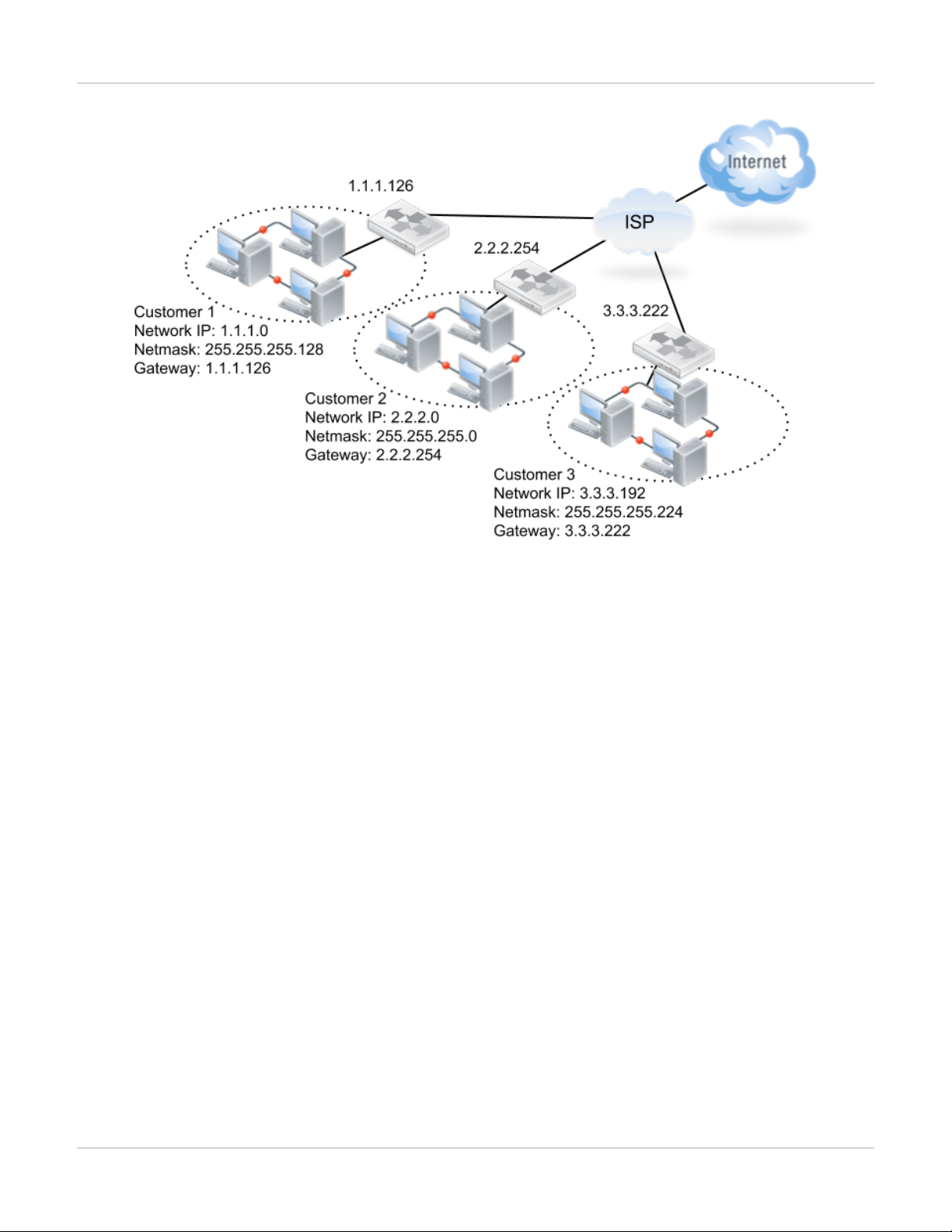
As for static IP addresses, ISP provides for clients in different ways. Generally, you obtain static IP addresses from ISP
in three types:
An available subnet
For example, ISP provides an ADSL link with a subnet 203.69.118.8/29 contains five host addresses, one gateway
address, one broadcast address and one for subnet ID. The result of subnet mask calculation shows there are eight IP
addresses in the subnet in total, which matches the IP addresses you obtained. In this case, the gateway is located at
your ATU-R which routes packets to ISP’s network. In the other words, the ATU-R connects a subnet with FortiWAN
and another subnet with ISP’s central office terminal in routing mode. You are suggested to configure the WAN link as
Routing Mode on FortiWAN for this application.
FortiWAN Handbook
Fortinet Technologies Inc.
16
Page 17
How to set up your FortiWAN Planning the network topology
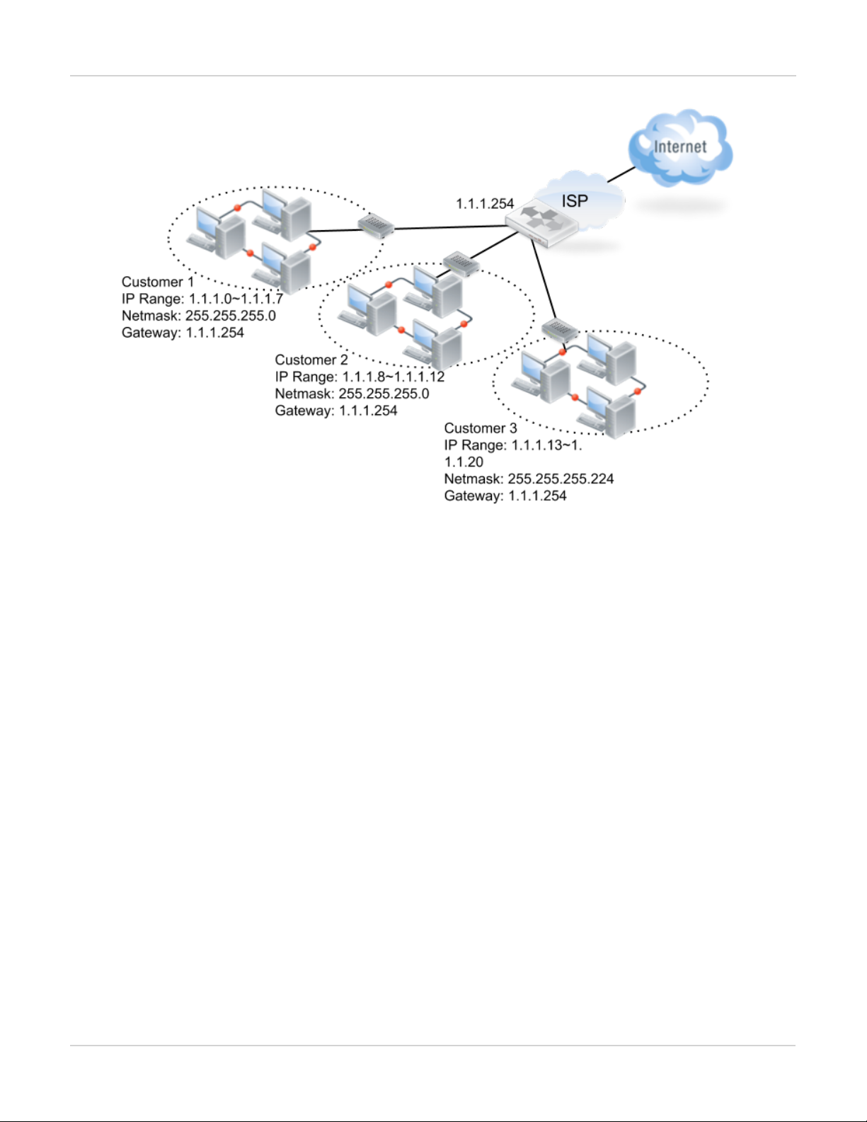
A range of static IP addresses in a shared subnet
For example, ISP provides an ADSL link with an IP range 61.88.100.1 ~3 that netmask is 255.255.255.0 and default
gateway is 61.88.100.254. The result of subnet mask calculation shows there are 256 IP addresses in the subnet in
total, but only 3 IP addresses you are allocated. In this case, the default gateway is located in ISP’s network and your
ATU-R only transfers packets to the gateway. In the other words, you are allocated in the same subnet with the ISP’s
central office, and the ATU-R takes the action to connect the two network segments in the subnet. You are suggested
configure the WAN link as Bridge Mode: Multiple Static IP or Bridge Mode: One Static IP on FortiWAN for this
application.
17 FortiWAN Handbook
Fortinet Technologies Inc.
Page 18
Planning the network topology How to set up your FortiWAN
See also
l
Configurations for a WAN link in Routing Mode
l
Configurations for a WAN link in Bridge Mode: One Static IP
l
Configurations for a WAN link in Bridge Mode: Multiple Static IP
l
Configurations for a WAN link in Brideg Mode: PPPoE
l
Configurations for a WAN link in Bridge Mode: DHCP
Near WAN
FortiWAN defines an area in WAN as near WAN, which traffic transferred in/from/to the area would not be counted to
the WAN links. That means traffic coming from or going to near WAN through a WAN port would not be controlled by
FortiWAN.
FortiWAN defines a near WAN for a WAN link in different ways between routing mode and bridge mode.
l In routing mode, the default gateway of a subnet deployed in WAN or in WAN and DMZ is near to FortiWAN.
Therefore, the area between the default gateway and FortiWAN is called near WAN. In the other words, FortiWAN
treats directly the subnet deployed on the WAN port as near WAN. The near WAN contains the default gateway.
l In bridge mode, the default gateway is located at ISP’s COT and the IP addresses allocated on FortiWAN are just a
small part of a subnet shared with others. Therefore, only the IP addresses deployed in WAN are treated as near
WAN (not include the remote gateway).
FortiWAN Handbook
Fortinet Technologies Inc.
18
Page 19
How to set up your FortiWAN Planning the network topology
This is the reason FortiWAN separates WAN link configuration into different type: routing mode and bridge mode (See
"WAN types: Routing mode and Bridge mode"). If you configure a bridge-mode WAN link that ISP provides on
FortiWAN as Routing Mode and the bridge-mode WAN link might belong to a shared class C subnet, FortiWAN treats
the whole class C network as near WAN, traffic goes to or comes from the class C network would be ignored for
FortiWAN’s balancing, management and statistics functions. That would be a big mistake.
See also
WAN types: Routing mode and Bridge mode
Public IP pass through (DMZ Transparent Mode)
Public IP Pass through makes the physical Ethernet segments connected to WAN port and DMZ port become one
logical segment, which is implemented by Proxy ARP (for IPv4) and ND Proxy (for IPv6). Therefore, one IP subnetwork
can be deployed over the two segments and accessibility between WAN and DMZ is the action taken without NAT or
routing. Note public IP pass through is available when a WAN link is configured as Routing mode with the deployment
of subnet in WAN and DMZ, or Bridge mode: multiple static IP with IP addresses being deployed in WAN and DMZ.
For the WAN link that ISP provides multiple static IP addresses (no matter routing mode or bridge mode), it’s very
convenient to deploy some public IP addresses in DMZ for external-facing services.
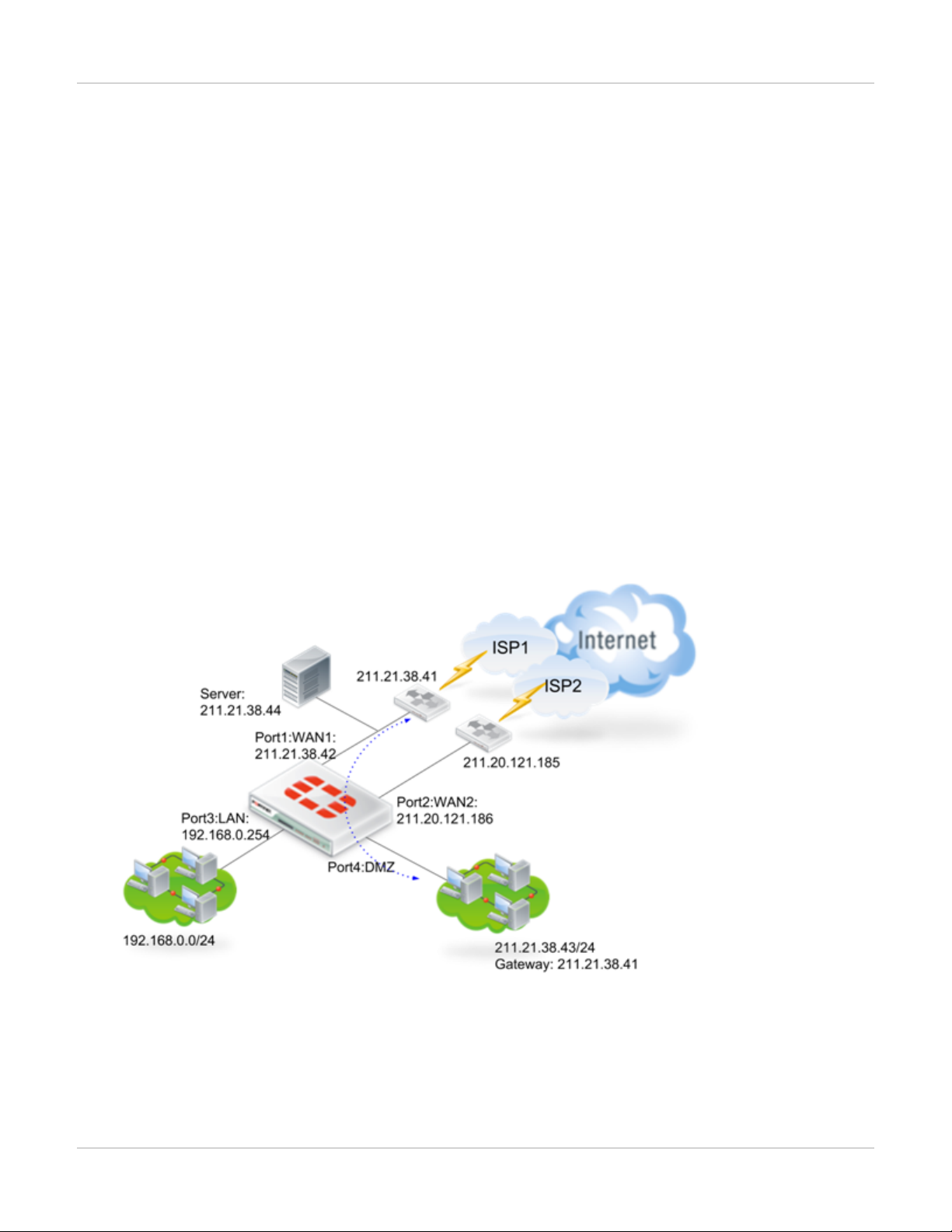
In the topology below, the PC in DMZ has been assigned with a public IP 211.21.38.43, in the same IP range with
port1. Public IP Pass-through actually indicates port4 has been transparently connected to port1 (shown in dotted line).
Thus, the PC in DMZ takes port1's gateway as its own gateway.
Public IP Pass-through minimizes the adaptation to current network structure and requires no changes on the
configuration for servers while a FortiWAN is deployed into.
19 FortiWAN Handbook
Fortinet Technologies Inc.
Page 20

Planning the network topology How to set up your FortiWAN
See also
l
WAN types: Routing mode and Bridge mode
l
Scenarios to deploy subnets
l
Configuring your WAN
Scenarios to deploy subnets
No matter an available subnet (routing mode) or an IP range of a shared subnet you obtain from ISP, you will need
making a plan how to deploy the multiple IP addresses.
To deploy the available subnet that ISP provides (routing mode) on FortiWAN, there are four different scenarios (be
called subnet types as well) for your options:
Subnet in WAN : Deploy the subnet in WAN.
Subnet in DMZ : Deploy the subnet in DMZ.
Subnet in WAN and DMZ : Deploy the subnet in both WAN and DMZ. FortiWAN’s Public IP Pass-
through function makes the two Ethernet segments in WAN and in DMZ one
IP subnetwork (See "Public IP Pass-through").
Subnet on Localhost : Deploy the whole subnet on localhost.
For cases of obtaining an IP range (bridge mode), the IP addresses could be allocated to:
IP(s) on Localhost : Allocate the IP addresses on localhost.
IP(s) in WAN : Allocate the IP addresses in WAN.
IP(s) in DMZ : Allocate the IP addresses in DMZ.
Static Routing Subnet
If there are subnets, which are called static routing subnets, connected to a basic subnet, it’s necessary to configure
the static routing for external accessing to the static routing subnets.
See also
l
WAN types: Routing mode and Bridge mode
l
Public IP Pass-through
l
Configuring your WAN
l
LAN Private Subnet
VLAN and port mapping
Customers can assign every physical port (except the HA port) to be a WAN port, LAN port or a DMZ port on demand,
which is called Port Mapping as well. The WAN ports, LAN ports and DMZ ports are actually physical ports on
FortiWAN Handbook
Fortinet Technologies Inc.
20
Page 21

How to set up your FortiWAN Planning the network topology
FortiWAN, they are just not at the fixed positions. The port mapping will be reflected in related configurations.
FortiWAN supports IEEE 802.1Q (also known as VLAN Tagging), but it does not support Cisco’s ISL. Every physical
port (except the HA port) can be divided into several VLAN with a VLAN switch, and those virtual ports can be mapped
to WAN port, LAN port or DMZ port as well.
See also
Configurations for VLAN and Port Mapping
IPv6/IPv4 Dual Stack
FortiWAN supports deployment of IPv6/IPv4 Dual Stack in [Routing Mode], [Bridge Mode: One Static IP], [Bridge
Mode: Multiple Static IP] and [Bridge Mode: PPPoE]. For configuration of IPv6/IPv4 Dual Stack, please select
appropriate WAN Type (See "WAN types: Routing mode and Bridge mode") for the WAN link according to the IPv4
you are provided by ISP as mentioned previously, and configure for IPv4 and IPv6 at the WAN link together. Except a
WAN IPv6 subnet used to deploy for a WAN link, ISP might provide an extra LAN IPv6 subnet for deploying your LAN.
Depending on the demand, the LAN IPv6 subnet can be deployed as basic subnet in DMZ as well for the WAN link.
FortiWAN in HA (High Availability) Mode
Installing FortiWAN in HA mode
When two FortiWAN units work together, they can be configured to HA (High Availability) double-device backup mode.
This setup allows two FortiWAN units to server as backup for each other. The master is the main functioning unit,
while the slave is the backup unit in standby. An FortiWAN unit alone already has built-in fault tolerance mechanism.
All its OS and control applications are stored in Flash Memory, so sudden loss of electricity will not damage the
system. But when the network must provide non-stop service for mission-critical applications, the HA mode becomes a
must. With HA, FortiWAN serves a significant solution to accomplish network fault tolerance.
FortiWAN supports hot backup in HA by heartbeat mechanism. When both FortiWAN are on, one unit (the master)
performs operations, with the other (the slave) in standby. If the master fails for power failure or hardware failure
(including normal power off and system reboot), hot backup performs a switch-over to the slave (heartbeat detection
fails). This function logically promotes the slave to activate HA and to resume the role of the master. The failed master
unit will take the role of slave after it resumes from reboot. The HA hot-backup solution significantly limits the
downtime, and secures uninterrupted operation for critical applications.
Hot backup also implies data synchronization. FortiWAN HA performs system configurations synchronization between
the master and slave units. Applying configurations to the master unit from Web UI triggers a synchronization to the
slave unit. Besides, as long as the peer unit resumes as slave mode from system rebooting, the master also
synchronizes system configures with it. This mechanism guarantees the identical system configurations for the two
units.
In case that two units are insistent with firmware version, FortiWAN model and throughput license, only one unit takes
the role of master but the peer unit stay the booting status. A master unit cannot synchronize system configurations
with the unit that is in booting status. A message "Incompatible" is displayed for Peer Information in the Summary
page of the master's Web UI.
21 FortiWAN Handbook
Fortinet Technologies Inc.
Page 22
Planning the network topology How to set up your FortiWAN
Setting Up HA
FortiWAN's double-device backup setup is easy to use. Simply connect the HA RJ-45ports on both FortiWAN units with
a Ethernet cable. Note that HA deployment requires identical firmware version, model and throughput license on the
two units.
Activating HA Mode
1. Install the master FortiWAN.
2. Connect the slave FortiWAN to the master with a Ethernet cable.
3. Switch on the slave.
After HA mode has been activated, the Master emits 4 beeps, and the Slave does 3. The status of the Slave is
displayed under [System] > [Summary] > [Peer Information] on the master's Web UI. Note that a slave's Web UI is not
available.
Once the master is down, the slave emits 1 beep and resumes the role of the master to keep network alive.
Switching on the two units together, then the unit with larger Up Time or Serial Number takes the role of master, while
the peer unit takes the role of slave.
Note: Ensure the cable is solidly plugged in both units. Otherwise, it may cause errors. After the master locates the
slave, system will activate HA mode.
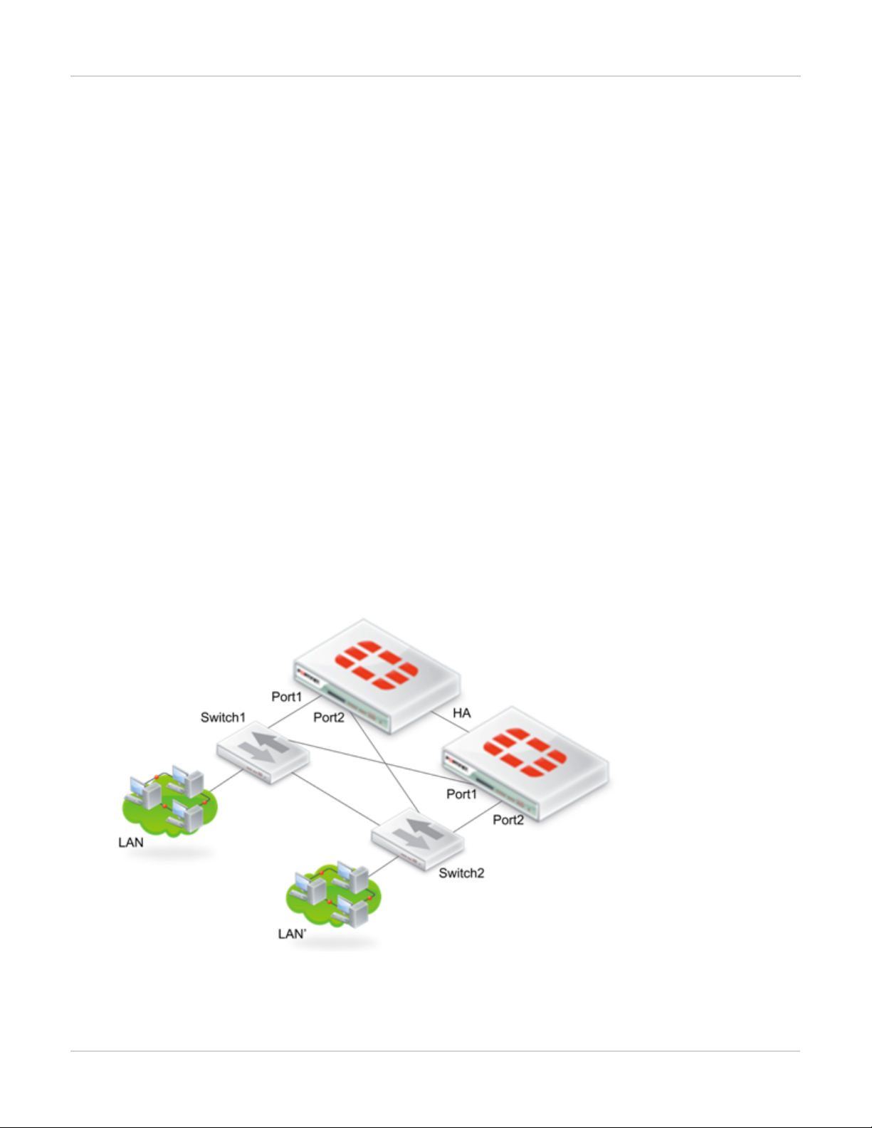
Redundant LAN Port and/or redundant DMZ port: FortiWAN in HA mode
As illustrated in the topology below, two FortiWAN units work in HA mode, with one active and the other in standby.
Port1 and port2 acts as redundant LAN port for each other, putting the two units into hot backup mode. This mode
offers a significant solution against single point failure in LAN/DMZ (See "Configurations for VLAN and Port
Mapping").
FortiWAN Handbook
Fortinet Technologies Inc.
22
Page 23

How to set up your FortiWAN Planning the network topology
High Availability (HA) Scenarios
Firmware Update Procedure in HA Deployment
The firmware update procedure in HA deployment differs from the non-HA (single unit) procedure:
1.
Log onto the master unit (unit A) as Administrator, go to [System]→[Summary] and double check and make sure
the peer device is under normal condition (See "Summary").
2. Execute the firmware update (See "Administrator"). Please wait as this may take a while.
3.
During the upgrade, do not turn off the system, unplug the power or repeatedly click the Submit button. The
message “Update succeeded” will appear after the upgrade is completed. System automatically reboots afterward
for the firmware to take effect.
4.
The slave unit (unit B) switches to be master while unit A rebooting. Note: The unit B will beep once.
5.
Log onto unit B Web UI. "Peer Information " might display "none" or "Booting". Then execute firmware update
procedure again.
6.
Make sure the firmware update steps are done and system reboots automatically.
7.
Unit A now switches to master while unit B rebooting.
8.
Login the unit A Web UI, go to [System] → [Summary], and make sure the system firmware is the latest version.
Also make sure the firmware is up to date on unit B.
Note: If there are abnormal behaviors in the DMZ or public IP servers, go to [System] → [Diagnostic Tools] →[ARP
Enforcement] and execute [Enforce] for troubleshooting. Also notice that if the Ethernet cable for HA between the
master and slave is removed or disconnected.
If abnormal behaviors appear consistently, please remove the network and HA cable, and perform the firmware update
procedure again to both system individually.Then reconnect them to the network as well as the HA deployment.
If repetitive errors occur during the firmware update process, DO NOT ever switch off the device and contact your
dealer for technical support.
HA Fallback to Single Unit Deployment
The steps to fallback to single unit deployment from HA are:
1.
Log onto Web UI via Administrator account. Go to [System] → [Summary]and double check and make sure the
peer device is under normal condition (See "Summary").
2.
Turn the Master off if the Master is to be removed. The Slave will take over the network immediately without
impacting services. If the Slave is to be removed, then simply turn the Slave off.
3.
Remove the device and the associated cables.
Steps of the Slave Take Over are:
1.
In the HA setup, the Master unit is in an active state and serving the network at the meanwhile the Slave unit is
monitoring the Master.
2.
In the case of unit failover (Hardware failure, Power failure, HA cable failure, etc), the Slave takes over the network
and beeps once when the switchover is completed. The switchover requires 15 seconds or so since negotiations
for states.
3.
The switched Master unit becomes the Slave unit in the HA deployment even it is repaired from failures. You can
power cycle the Master unit to have another switchover to the units.
23 FortiWAN Handbook
Fortinet Technologies Inc.
Page 24
Web UI Overview How to set up your FortiWAN
See also
l
Summary
l
Configurations for VLAN and Port Mapping
l
Administrator
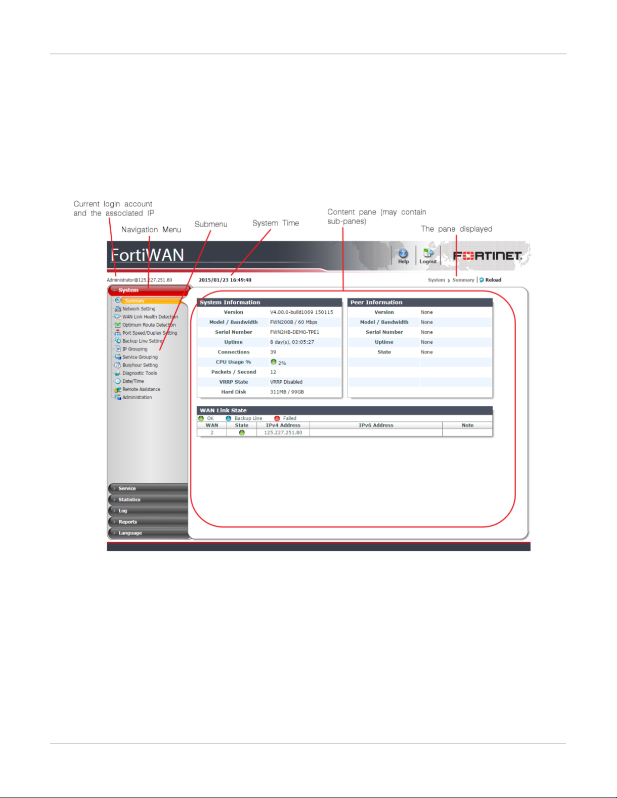
Web UI Overview
Once you log in, you will see the operating menu on FortiWAN Web UI. A navigation menu is located on the left side of
the web UI. The menu consists of six main functions: System, Service, Statistics, Log, Reports and Language.
Each function is divided into submenus. To expand a menu item, simply click it.To view the pages located within a
submenu, click the name of the page. [System/Summary] shown above indicates page contents are displayed of
[System] > [Summary], and [Administrator@125.227.251.80] indicates Administrator account log in from IP
125.227.251.80. Note that do not use your browser’s Back button to navigate, pages may not operate correctly.
l Apply: Click this button, to perform configurations or save configuration changes to memory. Before switching page,
remember to click [Apply]. Otherwise, changes will NOT be stored.
l Help: Click this button, to display online help for current page.
l Reload: Click this button, to reload page contents.
FortiWAN Handbook
Fortinet Technologies Inc.
24
Page 25

How to set up your FortiWAN Web UI Overview
FortiWAN manages most of its rules/filters/policies with top-down evaluation method where the rules are prioritized in
descending order.
Click this button, to add a new rule below the current rule.
Click this button, to delete the rule.
Click this button, to move the rule up a row.
Click this button, to move the rule down a row.
Write a note for this rule.
The function is disabled.
The function is enabled.
Using the web UI and the CLI
Be aware that the position of LAN port may vary depending on models. FortiWAN-200B, for example, has five network
interfaces, with its fourth interface as LAN port and fifth as DMZ port.
Before setting up FortiWAN in your network, ensure the following are taken care of:
l Check network environment and make sure the following are ready before FortiWAN installation and setup: well-
structured network architecture, and proper IP allocation.
l Use cross-over to connect PC to FortiWAN LAN port instead of straight-through.
To connect to the web UI
Requires: Microsoft Internet Explorer 6, Mozilla Firefox 2.0, or Google Chrome 2.0 or newer.
l Using the Ethernet cable, connect LAN port (port 4) of the appliance to your computer.
l Switch on FortiWAN. It will emit 3 beeps, indicating the system is initialized and activated. Meanwhile, the LAN port
LED blinks, indicating a proper connection.
l By default, the LAN IP address is 192.168.0.1. Configure your computer to match the appliance’s default LAN
subnet. For example, on Windows 7, click the Start (Windows logo) menu to open it, and then click Control Panel.
Click Network and Sharing Center, Local Area Connection, and then the Properties button. Select Internet Protocol
Version 4 (TCP/IPv4), then click its Properties button. Select Use the following IP address, then change your
computer’s settings to:
l IP address: 192.168.0.2 (or 192.168.0.X)
l Subnet mask: 255.255.255.0
l To connect to FortiWAN’s web UI, start a web browser and go to https://192.168.0.1. (Remember to include the “s”
in https://.)
l Login to web UI with the default username/password combinations: Administrator/1234 or Monitor/5678 (case
sensitive).
25 FortiWAN Handbook
Fortinet Technologies Inc.
Page 26

Web UI Overview How to set up your FortiWAN
Note:
1.
Make sure the proxy settings of the web browser are disabled. For example, open Internet Explorer and select
"Internet Option" on "Tools" menu. Click the "Connection" tab, "LAN settings" and open "Local Area Network
Settings" dialog box, then disable "Proxy server".
2.
Administrator has privileges to monitor and modify system parameters, while Monitor can monitor ONLY. It is
strong recommended that the passwords be changed ASAP, and store it in a safe and secure location.
3.
Only 1 Administrator can be logged in at one time. A 2nd Admin logging on will terminate the session of the 1st
login.
To connect to the CLI via serial console
Requires: Terminal emulator such as HyperTerminal, PuTTY, Tera Term, or a terminal server
l Using the console cable, connect the appliance’s console port to your terminal server or computer. On your
computer or terminal server, start the terminal emulator
l Use these settings:
l Bits per second: 9600
l Data bits: 8
l Parity: None
l Stop bits: 1
l Flow control: None
l Press Enter on your keyboard to connect to the CLI
l The default username/password is Administrator/fortiwan.
Note: FortiWAN CLI has limited functionality and cannot fully conigure the system. Normal configuration changes
should be done via the WebUI.
Using the web UI
FortiWAN's services (load balancing, fault tolerance and other optional services) are based on Policy and Filter.
Policies (or called Classes as well) are specified items indicating different actions for a service. Policies are applied to
different objects classified by the predefined filters. Basically, a object is classified by the combinations of When,
Source, Destination and TCP/UDP/ICMP Service. A filter contains the settings of those items When, Source,
Destination and Service, and also an associated Policy. Traffic that matches the filter will be applied to the specified
policy.
Configuration on When
This is for filtering traffic by different time period which is predefined in "Busyhour Settings".
Configuration on Source and Destination
This is for filtering the established sessions from/to specified source/destination. The options are:
IPv4/IPv6 Address : Matches sessions coming from or going to a single IPv4/IPv6 address. e.g.
192.168.1.4.
FortiWAN Handbook
Fortinet Technologies Inc.
26
Page 27

How to set up your FortiWAN Web UI Overview
IPv4/IPv6 Range : Matches sessions coming from or going to a continuous range of IP addresses.
e.g. 192.168.1.10-192.168.1.20.
IPv4/IPv6 Subnet : Matches sessions coming from or going to a subnet.
e.g.192.168.1.0/255.255.255.0.
WAN : Matches sessions coming from or going to WAN.
LAN : Matches sessions coming from or going to LAN.
DMZ : Matches sessions coming from or going to DMZ.
Localhost : Matches sessions coming from or going to FortiWAN.
Any Address : Matches all sessions regardless of its source or destination.
FQDN : Matches sessions coming from or going to FQDN.
IP Grouping Name : Matches sessions coming from or going to the IP addresses that predefined in IP
groups (See "IP Grouping").
Configuration on Service
This is for filtering the established sessions running specified service. It contains some well-known services for options
and user-defined services (TCP@, UDP@ and Protocol#):
l FTP (21)
l SSH (22)
l TELNET (23)
l SMTP (25)
l DNS (53)
l GOPHER (70)
l FINGER (79)
l HTTP (80)
l POP3 (110)
l NNTP (119)
l NTP (123)
l IMAP (143)
l SNMP (161)
l BGP (179)
l WAIS (210)
l LDAP (389)
l HTTPS (443)
l IKE (500)
l RLOGIN (513)
l SYSLOG (514)
l RIP (520)
l UUCP (540)
27 FortiWAN Handbook
Fortinet Technologies Inc.
Page 28

Web UI Overview How to set up your FortiWAN
l H323 (1720)
l RADIUS (1812)
l RADIUS-ACCT (1813)
l pcAnywhere-D (5631)
l pcAnywhere-S (5632)
l X-Windows (6000-6063)
l GRE
l ESP
l AH
l ICMP
l TCP@
l UDP@
l Protocol#
l Any
Console Mode Commands
This section provides further details on the Console mode commands. Before logging onto serial console via
HyperTerminal, please ensure the following settings are in place: Bits per second: 9600; Data bits: 8; Parity: None;
Stop bits: 1; Flow control: None.
help: Displays the help menu
help [COMMAND]
Show a list of console commands.
arping: Find the corresponding MAC address of an IP address
arping [HOST] [LINK] [INDEX]
Show the MAC address of an IP address. Host is the IP of the machine or domain name whose MAC address is of
interest. Link is the type of interface used, i.e. WAN, LAN and DMZ. If WAN is selected, please indicate the WAN port
number.
Example: "arping 192.168.2.100 lan" [enter] will send out an ARP packet from LAN port to query the MAC address of
the machine whose IP address is 192.168.2.100.
Note: If domain name is to be used in the HOST parameter, the DNS Server must be set in the Web UI [System]->
[Network Settings]->[DNS Server].
For more on ARP related error messages, please refer to other ARP materials.
disablefw: Disable firewall
disablefw
System will re-confirm, press [y] to proceed or [n] to cancel.
FortiWAN Handbook
Fortinet Technologies Inc.
28
Page 29

How to set up your FortiWAN Web UI Overview
enforcearp: Force FortiWAN's surrounding machines to update their ARP tables
enforcearp
Sytem will send ARP packets to update their ARP tables. This is for cases where after the initial installation of
FortiWAN, machines or servers sitting in the DMZ are unable to be able to connect to the internet.
httpctl: Control web server for Web User Interface
httpctl [restart|showport|setport [PORT]]
System will restart the web server running on FortiWAN for the Web UI, or display the port number occupied by the
web server, or reset the specified port number to the web server.
logout: Exit Console mode
logout
Exit the Console mode. The system will re-confirm, press [y] to proceed or [n] to cancel.
ping: Test network connectivity
ping [HOST] [LINK] [IDX]
Ping a HOST machine to detect the current WAN link status. HOST is the machine/device to be pinged. The LINK
parameter can be WAN, LAN or DMZ. If the LINK is WAN then also specify the WAN port number.
Example: "ping www.hinet.net wan 1" [Enter] to ping www.hinet.net via WAN #1.
Note: If domain name is used in the HOST parameter, DNS Server must be set in the Web UI [System]->[Network
Settings]->[DNS Server] (See "Set DNS server for FortiWAN").
For more on ICMP related error messages please refer to other ICMP/PING materials.
reactivate Reset to factory default and base bandwidth grade.
reboot: Restart FortiWAN
reboot | reboot [-t [SECOND]]
Restart FortiWAN. Type "reboot -t X" [Enter] to restart the FortiWAN after X amount of seconds.
Example: :reboot -t 5" [Enter] to restart the system in 5 seconds.
resetconfig: Restore to factory defaults
resetconfig | resetconfig [IP ADDRESS/NETMASK]
System will re-confirm, press [y] to proceed or [n] to cancel.
Type “resetconfig [IP address/Netmask]” to specify IP configuration to LAN port from resetting system to factory
default. Example: command “resetconfig 10.10.10.1/255.255.255.0” resets system to factory default, and the IP
configuration of LAN port becomes to 10.10.10.1 / 255.255.255.0 after system comes back up. IP configuration of
LAN port returns to 192.168.0.1/255.255.255.0 if system is reset without specification. Note that resetting system with
specification on LAN port disables all the WAN links by default.
29 FortiWAN Handbook
Fortinet Technologies Inc.
Page 30

Web UI Overview How to set up your FortiWAN
resetpasswd: Reset FortiWAN's Administrator and Monitor passwords to factory default
resetpasswd
System will re-confirm, press [y] to proceed or [n] to cancel.
setupport: Configure the transmission mode for all the FortiWAN port(s)
setupport [SHOW] | setupport change [INDEX] [SPEED] [MODE]
Type "setupport show" shows the current transmission modes for all the network ports.
Type "setupport change" [INDEX], then type "auto" [Enter] to change the index network port into AUTO mode.
Type "port-config change" [INDEX] [SPEED] [MODE] [Enter] to change the index network port into a specific
transmission mode.
INDEX: 1, 2, 3...
SPEED: 10, 100, 1000
MODE: half, full
Example: "setupport show" [Enter]
"setupport change 1 auto" [Enter]
"setupport change 2 100 full" [Enter]
Note:
Not all network devices support full 100M speed.
This command has no effect on fiber interface.
The INDEX is the port number of the FortiWAN port interface; exact number varies according to product models.
shownetwork: Show the current status of all the WAN links available
shownetwork
Display WAN Type, Bandwidth, IP(s) on Local/WAN/DMZ, Netmask, Gateway, and WAN/DMZ Port.
Example: "shownetwork" [Enter]
Note: This Console command can only show the current network status. This setting can be changed in the Web UI
under “Network Settings”.
showtrstat Display tunnel status
showtrstat [TR GROUP NAME]
Display the status of specified tunnel group.
sslcert: Set or unset SSL certificate for FortiWAN WebUI
sslcert show | sslcert set
Type “sslcert show” [Enter] to display current SSL certificate that FortiWAN WebUI is working with.
FortiWAN Handbook
Fortinet Technologies Inc.
30
Page 31

How to set up your FortiWAN Web UI Overview
Type “sslcert set” [Enter] to set new SSL certificate for working with FortiWAN WebUI. You have to manually input the
SSL private key and its correspondent certificate in text after the command prompt “sslcert>” line by line. The content
inputted for the private key and certificate must start with “-----BEGIN CERTIFICATE-----” and “-----BEGIN RSA
PRIVATE KEY-----”, and end with “-----END CERTIFICATE-----” and “----END RSA PRIVATE KEY-----”.
Example: "sslcert set" [Enter]
sslcert> -----BEGIN CERTIFICATE-----
sslcert> …(data encoded in Base64)…
sslcert> -----END CERTIFICATE-----
Type “sslcert reset” to reset to factory default, the self-signed certificate.
Note that command “sslcert show” displays no RSA private key to avoid possible information leakage.
sysctl: Controls the system parameters - [sip_helper] and [h323_helper].
sysctl sip_helper=[0|1] | sysctl h323_helper=[0|1]
sip_helper: to enable [1] or disable [0] SIP application gateway modules.
h323_helper: to enable [1] or disable [0] H323 application gateway modules.
Example: “sysctl sip_helper=0”[Enter] to disable the SIP application gateway modules.
Note: SIP and H323 application gateway modules execute NAT transparent for SIP and H323. Since NAT transparent
is a built-in function for some SIP and H323 devices, it is suggested to disable the SIP or H323 gateway module in
FortiWAN.
sysinfo: Display information regarding FortiWAN's CPU and memory
sysinfo
Display the status of FortiWAN’s CPU, memory and disk space.
tcpdump Dump network traffic
tcpdump [-aAdDeflLnNOpqRStuUvxX] [-c count] [-E algo:secret] [-i PORT] [-s snaplen] [-T
type] [-y datalinktype] [expression]
traceroute: Shows the packet routes between FortiWAN's port to a specified destination
traceroute [HOST] [TYPE] [INDEX]
Show the packet routes between the [INDEX] WAN ports to the [HOST] destination. [HOST] can be based on IP or
domain name. The LINK parameter can be WAN/LAN/DMZ. If the TYPE is WAN, then port number must also be
specified.
Example: "traceroute www.hinet.net wan 1" [Enter] to show the trace routes from WAN link1 to www.hinet.net.
Note: If the domain name is used in the HOST parameter, then the DNS Server must be set in the Web UI [System]->
[Network Settings]->[DNS Server] (See "Set DNS server for FortiWAN").
31 FortiWAN Handbook
Fortinet Technologies Inc.
Page 32

Configuring Network Interface (Network Setting) How to set up your FortiWAN
Configuring Network Interface (Network Setting)
This section enables administrators to configure WAN, LAN settings from Web UI. Explore the following to know more
about the five submenus in [System/Network Settings]:
DNS Server :
VLAN and Port Mapping : The feature enables administrators to map FortiWAN ports to WAN, LAN, or
WAN Setting : WAN Settings is the major part to deploy FortiWAN in various types of WAN
WAN/DMZ Private Subnet :
LAN Private Subnet :
Set DNS server for FortiWAN
The IP address of the DNS server in the network can be entered or modified
(See "Set DNS server for FortiWAN").
DMZ. In network that is using VLAN Switch (Virtual LAN Switch), FortiWAN
ports can even be mapped to VLAN Switch ports. In big network that is segmented into smaller groups of subnets by VLAN Switch, FortiWAN allows
data to exchange between these subnets. Through [VLAN Tags] settings,
VLAN Switch ports can even perform as DMZ, WAN or LAN (See "Con-
figurations for VLAN and Port Mapping").
links. Here are some information helping you on the configurations of WAN
Setting (See "Configuring your WAN").
This feature includes several configuration settings of WAN/DMZ port that
has private subnets (See "WAN/DMZ Private Subnet").
This feature includes several configuration settings of LAN port that has
private subnets (See "LAN Private Subnet").
[DNS Server] feature enables administrators to define the host name the FortiWAN in the network, the IPv4/IPv6
address of domain name servers used by FortiWAN, and the suffix of the domain name. The following lists Web UI
functions that may use the domain name servers here.
System/Diagnostic Tools :
Log/Control :
Log/Notification :
Serial Console :
Note: Incomplete DNS server configurations will not influence the performance of the functions listed above. Only IP
address is necessary instead of the FQDN.
FortiWAN Handbook
Fortinet Technologies Inc.
Ping and Trace (See "Diagnostic Tools")
SMTP and FTP Server Settings (See "Log Control")
SMTP Server Settings (See "Log Notification")
Ping and Traceroute Commands (See "Console Mode Commands")
32
Page 33

How to set up your FortiWAN Configuring Network Interface (Network Setting)
Configurations for VLAN and Port Mapping
VLAN and Port Mapping
FortiWAN supports IEEE 802.1Q (also known as VLAN Tagging), but it does not support Cisco’s ISL. Prior to its
deployment, it is better to get ports mapped, for example. Port1 mapped to WAN port. To better use FortiWAN with
VLAN Switch in the network, see the structure below:
As described, FortiWAN Port 1 is connected to VLAN switch, and VLAN tagging is required in the network. Thus
administrators can map the tags in [Mapping] and configure tagging in [VLAN Tag]. See below:
l Tag 101 --- WAN
l Tag 102 --- WAN
l Tag 103 --- LAN
l Tag 104 --- DMZ
After this configuration, FortiWAN port1 will no longer accept untagged VLAN packets. Port1.101 and port1.102 on
VLN Switch are directly connected with WAN links, while port1.103 is connected with PCs in LAN and port1.104 is
connected with PCs in DMZ. In this network, FortiWAN acts as the role of Router. PCs in DMZ can be assigned with
public IP addresses, with their packets transparently passing through FortiWAN to WAN. Apart from FortiWAN ports, it
is necessary to configure VLAN Switch as well, like the settings of tags and IP addresses. Note: This field (VRID) is
only available when VRRP mode is enabled in LAN Private Subnet settings. The VRID indicates the virtual router
identifier for every VR.
Redundant LAN/DMZ Port and Aggregated LAN/DMZ Port
Why redundant LAN port and redundant DMZ port are necessary? Because without these two ports, when FortiWAN is
working in HA mode, single point failure can still occur over links connecting LAN/DMZ and LAN/DMZ ports on
FortiWAN. FortiWAN bridges the connections of redundant LAN port and redundant DMZ port. It supports the
Spanning Tree algorithm and sets the highest 0xffff as bridge priority. The configurations thus manage to avoid
33 FortiWAN Handbook
Fortinet Technologies Inc.
Page 34

Configuring Network Interface (Network Setting) How to set up your FortiWAN
network failure caused by the possible packet looping. In addition, the aggregation of both ports can be used to
increase 1x bandwidth, while also offer HA backup support.
Label : The logical label of the redundant LAN/DMZ or aggregated LAN/DMZ port pair that is grouped by
a selection of two ports. The label is used for later reference in other configurations. The label
can only contain letters of “0-9 a-z A-Z .-_”, and will display in LAN settings as one option.
Mapping : Select two LAN/DMZ ports and group them as redundant LAN/DMZ or aggregated LAN/DMZ
port pair.
As illustrated in the topology below, FortiWAN port1 are mapped to WAN port. Port2 and port3 are configured as the
redundant LAN ports which are connected to Switch1, port4 and port5 as the redundant DMZ ports which are
connected to Switch2. In this case, once one of the two LAN/DMZ links breaks down, FortiWAN will enable the other
LAN/DMZ link to resume the traffic.
Configure [VLAN and Port Mapping] from the Web UI. In this example, Port 1 is set as WAN, Port 2 and Port 3 as HA
LAN port pair and Port 4 and 5 as HA DMZ port pair. Each of the LAN/DMZ pair is connected via a single switch (switch
1 or switch 2). This will remove the chance of single point failure on the switch, and the entire system will be in ‘HA’.
As illustrated in the topology below, two FortiWAN units work in HA mode (See "FortiWAN in HA (High Availability)
Mode"), with one active and the other in standby. Port1 and port2 acts as redundant LAN port for each other, putting
the two units into hot backup mode. This mode offers a significant solution against single point failure in LAN/DMZ.
FortiWAN Handbook
Fortinet Technologies Inc.
34
Page 35

How to set up your FortiWAN Configuring Network Interface (Network Setting)
Configuring your WAN
[WAN Settings] is the major part to deploy FortiWAN in various types of WAN links. If your network has several WAN
links, you have to configure one after another. Select any link from [WAN link] and check [Enable] to start a
configuration of the WAN connection (See "WAN link and WAN port"). A configuration of WAN link is divided into
three parts: Basic Settings, Basic Subnet and Static Routing Subnet. Before starting configuration, here are several
important concepts you should know.
WAN Type
The first step to start a WAN link configuration is deciding the WAN type. Configuration varies on [WAN Type] in [Basic
Settings]. The [WAN Type] could be one of:
l
Routing Mode (See "Configurations for a WAN link in Routing Mode")
l
Bridge Mode: One Static IP (See "Configurations for a WAN link in Bridge Mode: One Static IP")
l
Bridge Mode: Multiple Static IP (See "Configurations for a WAN link in Bridge Mode: Multiple Static IP")
l
Bridge Mode: PPPoE (See "Configurations for a WAN link in Brideg Mode: PPPoE")
l
Bridge Mode: DHCP Client (See "Configurations for a WAN link in Bridge Mode: DHCP")
Basic Setting & Basic Subnet & Static Routing Subnet
Basic Setting :
Basic Setting is the necessary settings for a WAN link, such as WAN type, up/-
download bandwidth, threshold, netmask, gateway and the localhost IP, to
enable data transmission on a WAN link. The setting fields varies on the WAN types.
35 FortiWAN Handbook
Fortinet Technologies Inc.
Page 36

Configuring Network Interface (Network Setting) How to set up your FortiWAN
Basic Subnet : Basic Subnet is the configuration for the subnets deployed on a WAN link. You decide
the subnet type (or ignore it) according to your various requirements and the network
ISP provides.
Static Routing Subnet : If there are subnets, which are called static routing subnets, connected to a basic sub-
net, it’s necessary to configure the static routing for external accessing to the static
routing subnets.
See also
l
WAN link and WAN port
l
Configurations for a WAN link in Routing Mode
l
Configurations for a WAN link in Bridge Mode: One Static IP
l
Configurations for a WAN link in Bridge Mode: Multiple Static IP
l
Configurations for a WAN link in Brideg Mode: PPPoE
l
Configurations for a WAN link in Bridge Mode: DHCP
Configurations for a WAN link in Routing Mode
Basic Setting
Select [Routing Mode] from [WAN Type], and configure parameters in [Basic Settings]. Note that localhosts of
FortiWAN’s WAN and DMZ ports belong to the basic subnet in Routing Mode; therefore at least one basic subnet is
required. For the reason, [Basic Setting] contains no fields for setting IP(s) on Localhost and Netmask, which are the
fields in [Basic Subnet].
WAN Port : The physical port (network interface) on FortiWAN used to connect the WAN
link. For the deployment of multiple WAN links on one WAN port, set this field
with the same value for those WAN links. For example, select Port1 for configurations of WAN link1, WAN link2 and WAN link3 for deploying the three
WAN links on WAN port1. Note: The port has to be mapped to [WAN] beforehand in [VLAN and Port Mapping] (See "WAN link and WAN port", "VLAN and
port mapping" and "Configurations for VLAN and Port Mapping").
Up/Down Stream : The WAN link's transfer speed at which you can upload/download data to/from
the Internet e.g. 512Kbps.
Up/Down Stream Threshold : Specify upstream/downstream (Kbps) threshold for the WAN link. WAN link
with traffic that exceeds the threshold values will be considered as failed.
FortiWAN’s Auto Routing and Multihoming (See "Outbound Load Balancing
and Failover (Auto Routing)" and "Inbound Load Balancing and Failover (Multi-
homing)") use the value while balancing traffic between WAN links if the
Threshold function is enabled. Leave it blank or zero if you do not apply
threshold to the WAN link.
FortiWAN Handbook
Fortinet Technologies Inc.
36
Page 37

How to set up your FortiWAN Configuring Network Interface (Network Setting)
MTU : (Maximum Transmission unit) refers to the size of the largest packet or frame
that a given layer of a communications protocol can pass onwards. It allows
dividing the packet into pieces, each small enough to pass over a single link.
IPv4 Gateway : The IPv4 address of the default gateway. This field is mandatory.
IPv6 Gateway : The IPv6 address of the default gateway. This field is optional. Ignore it for
IPv4 WAN links or configure it for IPv4/IPv6 dual stack WAN links.
Basic Subnet and Static Routing Subnet
As mentioned previously, FortiWAN’s Routing Mode plays the role routing packets between subnets. For applications
deploying different subnets in FortiWAN’s WAN or (and) DMZ, you are required to complete configuration of the
subnets. There are two majore types of subnets for your options to deploy.
IPv4 / IPv6 Basic Subnet
Basic subnets are subnets connected directly to FortiWAN. According to the location a subnet deployed to, Basic
Subnet (See "Scenarios to deploy subnets") is divided into:
l Subnet in WAN: A subnet deployed in WAN.
l Subnet in DMZ: A subnet deployed in DMZ.
l Subnet in WAN and DMZ: A subnet deployed in WAN and DMZ. The subnet that is on the same network segment is
implemented by Proxy ARP.
l Subnet on Localhost (Not support for [IPv6 Basci Subnet])
Among these, [Subnet in WAN and DMZ] is the most general basic subnet for deplyment. You can have multiple basic
subnets for various requirements, such as one subnet in WAN and another subnet in DMZ, or one subnet in WAN and
DMZ and another subnet in DMZ. Note that it is necessary to deploy at least one subnet in WAN or subnet in WAN and
DMZ for a WAN link. you cannot configure a WAN link containing only one basic subnet which is deployed in DMZ. The
field “IP(s) on Localhost” in configuration of Subnet in DMZ is for assigning IP(s) on the DMZ port, not for WAN port. It
requires at least one IP address be assigned to localhost of a WAN port for data transmission via the WAN link, which
means at least one subnet in WAN or one subnet in WAN and DMZ is required in routing mode.
IPv4 / IPv6 Static Routing Subnet
Static routing subnets are the subnets connected indirectly to FortiWAN via a router or an L3 switch (See "Scenarios to
deploy subnets"). According to the location a subnet deployed to, Static Routing Subnet is divided into:
l Subnet in WAN: A static routing subnet deployed in WAN, connected to a basic subnet in WAN or basic subnet in
WAN and DMZ.
l Subnet in DMZ: A static routing subnet deployed in DMZ, connected to a basic subnet in DMZ or basic subnet in
WAN and DMZ.
Next comes a few examples to further illustrate configurations in [Basic Subnet] and [Static Routing Subnet].
37 FortiWAN Handbook
Fortinet Technologies Inc.
Page 38

Configuring Network Interface (Network Setting) How to set up your FortiWAN
Examples of Basic Subnets
[Basic Subnet]: Subnet in WAN
This topology is frequently found where cluster hosts on a IPv4 public subnet are deployed in WAN.
As described in the topology, FortiWAN uses port2 as WAN port with IP address 203.69.118.10. Its netmask obtained
from ISP is 255.255.255.248, and the router's IP address 203.69.118.9. IP addresses that are unlisted in [IP(s) on
localhost], 203.69.118.11 – 203.69.118.14 in this case, can be used for hosts in the subnet in WAN. In this case, IP
addresses 203.69.118.9 – 203.69.118.14 are treated as in near WAN.
[Basic Subnet]: Subnet in DMZ
This topology is frequently found where a cluster of hosts in an IPv4 subnet are deployed in DMZ. Base on the
topology introduced previously, click the [+] button to add a subnet in DMZ. Remember a subnet in DMZ must
coexist with a subnet in WAN or a subnet in WAN and DMZ.
FortiWAN Handbook
Fortinet Technologies Inc.
38
Page 39

How to set up your FortiWAN Configuring Network Interface (Network Setting)
As described in the topology, since the cluster of hosts are deployed in DMZ. FortiWAN port5 has to be mapped to
DMZ with IP address 140.112.8.9. Thus the hosts in the subnet take the default gateway as 140.112.8.9. In this case,
IP addresses 203.69.118.9 – 203.69.118.14 are treated as in near WAN, while IP addresses 140.112.8.9 –
140.112.8.14 in DMZ do not belong to near WAN. Check [Enable DHCP] if hosts in the subnet in DMZ require DHCP
service. And enter the starting and ending address in [DHCP Range]. If any host in the subnet uses static IP address,
then in [Static Mapping], enter its IP and MAC address. Similarly, if ISP provides another LAN IPv6 subnet, you can
deploy it in DMZ. The SLAAC and DHCPv6 in FortiWAN are designed to work together, which SLAAC responses router
advertisement (including default gateway and DNS server) to a host and DHCPv6 responses the host an appropriate
IPv6 address. Note: FortiWAN assumes that IP addresses that are unlisted in [IP(s) on Localhost] can be used for
hosts in the subnet.
[Basic Subnet]: Subnet in WAN and DMZ
This topology is frequently found where a cluster of hosts in one subnet are deployed in both WAN side and DMZ side.
39 FortiWAN Handbook
Fortinet Technologies Inc.
Page 40

Configuring Network Interface (Network Setting) How to set up your FortiWAN
As described in the topology, port2 and port5 are connected in dotted line, indicating an IP range in the same subnet
203.69.118.8/29 spreads across WAN (port2) and DMZ (port5). FortiWAN employs Proxy ARP to connect those hosts
becoming in the same network segment (See "Public IP pass through (DMZ Transparent Mode)").
Note that although IP address 203.69.118.9 has been configured as default gateway in Basic Setting table, you are
still required to add it in the field [IP(s) in WAN]. When you select [Subnet in WAN and DMZ] from [Subnet Type],
FortiWAN will assume the IP addresses that are unlisted in [IP(s) on Localhost] and [IP(s) in WAN] are all in DMZ.
Thus, in this example, except 203.69.118.10, 203.69.118.9 and 203.69.118.11-203.69.118.12, the rest IP addresses
of subnet 203.69.118.8/29 are assigned to DMZ for Public IP Pass-through. In this case, IP addresses 203.69.118.9 –
203.69.118.12 in WAN side are treated as in near WAN, while IP addresses 203.69.118.13 – 203.69.118.14 in DMZ
side do not belong to near WAN.
Check [Enable DHCP] if hosts in the subnet in DMZ require DHCP service. And enter the starting and ending address
in [DHCP Range]. If any host in the subnet uses static IP address, then in [Static Mapping], enter its IP and MAC
address. Similarly, the configuration to deploy an IPv6 public subnet in WAN and DMZ.
[Basic Subnet]: Subnet on Localhost
This topology is found where subnet is designated on FortiWAN to better use Virtual Server.
FortiWAN Handbook
Fortinet Technologies Inc.
40
Page 41

How to set up your FortiWAN Configuring Network Interface (Network Setting)
As described in the UI, the subnet as a whole is assigned to Virtual Server for use. Enter subnet IP address in [Network
IP] and netmask 255.255.255.248 in [Netmask].
Examples of Static Routing Subnets
[Static Routing Subnet]: Subnet in WAN
This topology is rarely seen in actual network where static routing subnet is located on the WAN. In other words, the
subnet in WAN does not connect to FortiWAN directly, but needs a router instead to transfer packets. In this example,
a subnet 139.3.1.8/29 is located on the WAN and connects to router 203.69.118.9, while another subnet
203.69.118.8/29 is located on the WAN as well, but connects to FortiWAN directly. The configurations here indicate
how FortiWAN to route packets to subnet 139.3.1.8/29.
41 FortiWAN Handbook
Fortinet Technologies Inc.
Page 42

Configuring Network Interface (Network Setting) How to set up your FortiWAN
As described in the UI, FortiWAN transfers packets to the gateway 203.69.118.9 to deliver them to subnet
139.3.1.8/255.255.255.248.
[Static Routing Subnet]: Subnet in DMZ
This topology is similar with the one in last example [Static Routing Subnet]: Subnet in WAN. The only difference is
subnet is in DMZ this time.
FortiWAN Handbook
Fortinet Technologies Inc.
42
Page 43

How to set up your FortiWAN Configuring Network Interface (Network Setting)
As described in the UI, FortiWAN transfers packets to the gateway 203.69.118.14 to deliver them to subnet
139.3.1.8/255.255.255.248
See also
l
WAN link and WAN port
l
VLAN and port mapping
l
Configurations for VLAN and Port Mapping
l
Outbound Load Balancing and Failover (Auto Routing)
l
Inbound Load Balancing and Failover (Multihoming)
l
Scenarios to deploy subnets
l
Public IP pass through (DMZ Transparent Mode)
l
IPv6/IPv4 Dual Stack
Configurations for a WAN link in Bridge Mode: Multiple Static IP
[Bridge Mode: Multiple Static IPs] is used for a range of static IPv4 addresses of a C class network from ISP. The
netmask is 255.255.255.0 and the ATU-R ISP provided is bridge-mode. FortiWAN’s Bridge Mode: Multiple Static IP is
suggested to apply for this case. The multiple IPv4 addresses can be deployed in WAN or in DMZ where is a logical
network segment via ProxyARP between the two physical ports. IPv4 basic subnets are not supported here, however, it
supports IPv6 basic subnets as previous cases.
43 FortiWAN Handbook
Fortinet Technologies Inc.
Page 44

Configuring Network Interface (Network Setting) How to set up your FortiWAN
Basic Setting
WAN Port : The physical port (network interface) on FortiWAN used to connect the WAN
link. For the deployment of multiple WAN links on one WAN port, set this field
with the same value for those WAN links. For example, select Port1 for configurations of WAN link1, WAN link2 and WAN link3 for deploying the three
WAN links on WAN port1. Note: The port has to be mapped to [WAN] beforehand in [VLAN and Port Mapping] (See "WAN link and WAN port", "VLAN and
port mapping" and "Configurations for VLAN and Port Mapping").
Up/Down Stream : The WAN link's transfer speed at which you can upload/download data to/from
the Internet e.g. 512Kbps.
Up/Down Stream Threshold : Specify upstream/downstream (Kbps) threshold for the WAN link. WAN link
with traffic that exceeds the threshold values will be considered as failed.
FortiWAN’s Auto Routing and Multihoming (See "Outbound Load Balancing
and Failover (Auto Routing)" and "Inbound Load Balancing and Failover (Multi-
homing)") use the value while balancing traffic between WAN links if the
Threshold function is enabled. Leave it blank or zero if you do not apply
threshold to the WAN link.
MTU : (Maximum Transmission unit) refers to the size of the largest packet or frame
IPv4 IP(s) on Localhost :
IPv4 IP(s) in WAN :
IPv4 IP(s) in DMZ :
IPv4 Netmask : The IPv4 netmask that ISP provides.
IPv4 Gateway : The IPv4 address of the default gateway.
IPv6 IP(s) on Localhost :
IPv6 IP(s) in WAN :
IPv6 IP(s) in DMZ :
that a given layer of a communications protocol can pass onwards. It allows
dividing the packet into pieces, each small enough to pass over a single link.
The IPv4 addresses that are deployed on localhost (See "Scenarios to deploy
subnets").
The IPv4 addresses that are deployed in WAN (See "Scenarios to deploy sub-
nets").
The IPv4 addresses that are deployed in DMZ (See "Scenarios to deploy sub-
nets").
The IPv6 addresses that are deployed on localhost (See "Scenarios to deploy
subnets").
The IPv6 addresses that are deployed in WAN (See "Scenarios to deploy sub-
nets").
The IPv6 addresses that are deployed in DMZ (See "Scenarios to deploy sub-
nets").
IPv6 Prefix : The IPv6 prefix that ISP provides.
IPv6 Gateway : The IPv6 address of the default gateway.
Enable SLAAC : Check to enable SLAAC.
FortiWAN Handbook
Fortinet Technologies Inc.
44
Page 45

How to set up your FortiWAN Configuring Network Interface (Network Setting)
Subnet : The IPv6 subnet deployed on the WAN link.
DMZ Port : The DMZ port for the IPv6 subnet.
Enable DHCP : Check to enable DHCP.
DHCP Range : Specify the range of IPv4 addresses for DHCP to use.
Static Mapping : Specify the static mapping between IPv4 Addresses and MAC addresses.
Enable DHCPv6 Service : Check to enable DHCPv6.
DHCP Range : Specify the range of IPv6 addresses for DHCP to use.
Static Mapping : Specify the static mapping between IPv6 Addresses and client IDs.
The SLAAC and DHCPv6 in FortiWAN are designed to work together, which the SLAAC responses router
advertisement (including default gateway and DNS server) to a host and DHCPv6 responses the host an appropriate
IPv6 address.
This topology can be seen where a group of valid IP addresses ranging 211.21.40.32~211.21.40.34 have been given
by ISP and assigned to port1 on FortiWAN. And their default gateway is 211.21.40.254 given by ISP as well.
If there are other hosts deployed on the WAN, then configure their IP addresses in [IP(s) in WAN]. And if there are
hosts deployed on the DMZ, then configure their IP addresses in [IP(s) in DMZ]. Check [Enable DHCP] if hosts in the
subnet in DMZ require DHCP service. And enter the starting and ending address in [DHCP Range]. If any host in the
subnet uses static IP address, then in [Static Mapping], enter its IP and MAC address.
See also
l
WAN link and WAN port
l
VLAN and port mapping
l
Configurations for VLAN and Port Mapping
l
Outbound Load Balancing and Failover (Auto Routing)
l
Inbound Load Balancing and Failover (Multihoming)
l
Scenarios to deploy subnets
l
Public IP pass through (DMZ Transparent Mode)
l
IPv6/IPv4 Dual Stack
Configurations for a WAN link in Bridge Mode: One Static IP
[Bridge Mode: One Static IP] is used when ISP gives one static IPv4 address to a user. Usually, the IPv4 address a
user obtained is one IP address of a C class IPv4 network; it is indicated by the netmask 255.255.255.0. The default
gateway that ISP assigned is located at ISP’s network, while the ATU-R works in bridge mode. FortiWAN’s Bridge
Mode: One Static IP is suggested to apply for this case. IPv6/IPv4 dual static is supported for FortiWAN’s Bridge
Mode: One Static IP. In the dual static similar as previous case, ISP might provide you a WAN IPv6 subnet and a LAN
IPv6 subnet. You can deploy the LAN IPv6 subnet as a basic subnet in DMZ. Although the deployment is under
FortiWAN’s Bridge Mode, FortiWAN routes packets between WAN and DMZ for the IPv6 subnets. Basic subnets are
not supported for IPv4 network deployed in Bridge Mode. The following topology is widely seen where a user gets one
static IP from ISP.
45 FortiWAN Handbook
Fortinet Technologies Inc.
Page 46

Configuring Network Interface (Network Setting) How to set up your FortiWAN
Basic Setting
WAN Port: The physical port (network interface) on FortiWAN used to connect the WAN link. For the deployment of
multiple WAN links on one WAN port, set this field with the same value for those WAN links. For example, select Port1
for configurations of WAN link1, WAN link2 and WAN link3 for deploying the three WAN links on WAN port1. Note: The
port has to be mapped to [WAN] beforehand in [VLAN and Port Mapping].
Up/Down Stream
Up/Down Stream Threshold : Specify upstream/downstream (Kbps) threshold for the WAN link. WAN link
MTU : (Maximum Transmission unit) refers to the size of the largest packet or frame
IPv4 Localhost IP :
IPv4 Netmask : The IPv4 netmask that ISP provides.
The WAN link's transfer speed at which you can upload/download data to/from
:
the Internet e.g. 512Kbps
with traffic that exceeds the threshold values will be considered as failed.
FortiWAN’s Auto Routing and Multihoming (See "Outbound Load Balancing
and Failover (Auto Routing)" and "Inbound Load Balancing and Failover (Multi-
homing)") use the value while balancing traffic between WAN links if the
Threshold function is enabled. Leave it blank or zero if you do not apply
threshold to the WAN link.
that a given layer of a communications protocol can pass onwards. It allows
dividing the packet into pieces, each small enough to pass over a single link.
The IPv4 address that ISP provides (See "Scenarios to deploy subnets").
IPv4 Gateway : The IPv4 address of the default gateway.
IPv6 Localhost IP :
FortiWAN Handbook
Fortinet Technologies Inc.
The IPv6 address that ISP provides (See "Scenarios to deploy subnets").
46
Page 47

How to set up your FortiWAN Configuring Network Interface (Network Setting)
IPv6 Prefix : The IPv6 prefix that ISP provides.
IPv6 Gateway : The IPv6 address of the default gateway.
See also
l
WAN link and WAN port
l
VLAN and port mapping
l
Configurations for VLAN and Port Mapping
l
Outbound Load Balancing and Failover (Auto Routing)
l
Inbound Load Balancing and Failover (Multihoming)
l
Scenarios to deploy subnets
l
IPv6/IPv4 Dual Stack
Configurations for a WAN link in Brideg Mode: PPPoE
[Bridge Mode: PPPoE] is used for PPPoE WAN link (ISP provides dynamic or static IP addresses via PPPoE). In [Basic
Settings], you shall configure upstream and downstream, user name, password and service name given by ISP. Left
[IP Address] blank if you are assigned an dynamic IP address; otherwise, enter your static IP address. Select an
FortiWAN WAN port to which PPPoE ADSL Modem is connected, e.g. port1. Checks [Redial Enable] to enable redial.
As some ISPs automatically reconnect to the network within a certain time interval, [Redial Enable] will avoid
simultaneous redialing of WAN links, which properly staggers WAN redial time. In case of connecting several
DHCP/PPPoE WAN links to the same ISP, the connections might fail if they are deployed on the same physical WAN
port via VLAN because the same MAC address. Via [Clone MAC Enable] you can configure MAC address clone on
FortiWAN for this deployment.
Basic Setting
WAN Port : The physical port (network interface) on FortiWAN used to connect the WAN
link. For the deployment of multiple WAN links on one WAN port, set this field
with the same value for those WAN links. For example, select Port1 for configurations of WAN link1, WAN link2 and WAN link3 for deploying the three
WAN links on WAN port1. Note: The port has to be mapped to [WAN] beforehand in [VLAN and Port Mapping] (See "WAN link and WAN port", "VLAN and
port mapping" and "Configurations for VLAN and Port Mapping").
Up/Down Stream : The WAN link's transfer speed at which you can upload/download data to/from
the Internet e.g. 512Kbps.
Up/Down Stream Threshold : Specify upstream/downstream (Kbps) threshold for the WAN link. WAN link
with traffic that exceeds the threshold values will be considered as failed.
FortiWAN’s Auto Routing and Multihoming (See "Outbound Load Balancing
and Failover (Auto Routing)" and "Inbound Load Balancing and Failover (Multi-
homing)") use the value while balancing traffic between WAN links if the
Threshold function is enabled. Leave it blank or zero if you do not apply
threshold to the WAN link.
47 FortiWAN Handbook
Fortinet Technologies Inc.
Page 48

Configuring Network Interface (Network Setting) How to set up your FortiWAN
MTU : (Maximum Transmission unit) refers to the size of the largest packet or frame
that a given layer of a communications protocol can pass onwards. It allows
dividing the packet into pieces, each small enough to pass over a single link.
User Name : Fill in the Username provided by ISP.
Password : Fill in Password provided by ISP.
Service Name : Fill in service name provided by ISP. Left it blank if ISPs do not require it.
IPv4 Address : Fill in the IPv4 address provided by ISP. Left it blank if ISPs do not require it.
IPv6 Enable : Check to enable IPv6 over PPPoE.
Redial Enable : Since some ISPs tend to turn off PPPoE connection at a certain schedule,
FortiWAN will automatically re-establish every disconnected PPPoE link when
detected. In order to prevent simultaneous re-connection of multiple links, different re-connection schedules can be configured for different WAN links to
avoid conjunction. After reconnection schedule is configured (HH:MM), the system will perform PPPoE reconnection as scheduled daily.
Clone MAC Enable : Configure MAC address clone.
See also
l
WAN link and WAN port
l
VLAN and port mapping
l
Configurations for VLAN and Port Mapping
l
Outbound Load Balancing and Failover (Auto Routing)
l
Inbound Load Balancing and Failover (Multihoming)
Configurations for a WAN link in Bridge Mode: DHCP
[Bridge Mode: DHCP Client] is used when FortiWAN WAN port gets a dynamic IP address from DHCP host. IPv6 is not
supported in this WAN type.
Basic Setting
WAN Port : The physical port (network interface) on FortiWAN used to connect the WAN
link. For the deployment of multiple WAN links on one WAN port, set this field
with the same value for those WAN links. For example, select Port1 for configurations of WAN link1, WAN link2 and WAN link3 for deploying the three
WAN links on WAN port1. Note: The port has to be mapped to [WAN] beforehand in [VLAN and Port Mapping]. (See "WAN link and WAN port", "VLAN and
port mapping" and "Configurations for VLAN and Port Mapping")
Up/Down Stream :
FortiWAN Handbook
Fortinet Technologies Inc.
The WAN link's transfer speed at which you can upload/download data to/from
the Internet e.g. 512Kbps
48
Page 49

How to set up your FortiWAN Configuring Network Interface (Network Setting)
Up/Down Stream Threshold : Specify upstream/downstream (Kbps) threshold for the WAN link. WAN link
with traffic that exceeds the threshold values will be considered as failed.
FortiWAN’s Auto Routing and Multihoming (See "Outbound Load Balancing
and Failover (Auto Routing)" and "Inbound Load Balancing and Failover (Multi-
homing)") use the value while balancing traffic between WAN links if the
Threshold function is enabled. Leave it blank or zero if you do not apply
threshold to the WAN link.
MTU : (Maximum Transmission unit) refers to the size of the largest packet or frame
that a given layer of a communications protocol can pass onwards. It allows
dividing the packet into pieces, each small enough to pass over a single link.
Clone MAC Enable : Configure MAC address clone.
See also
l
WAN link and WAN port
l
VLAN and port mapping
l
Configurations for VLAN and Port Mapping
l
Outbound Load Balancing and Failover (Auto Routing)
l
Inbound Load Balancing and Failover (Multihoming)
LAN Private Subnet
[LAN Private Subnet] is the second most important part for deploying FortiWAN in your network. In contrast with
configurations on WAN Settings to active the WAN link transmission from FortiWAN to Internet (external network),
LAN Private Subnet is the configuration for deploying the internal network on FortiWAN’s LAN ports. There are two
parts for setting LAN private subnet: Basic Subnet and Static Routing Subnet, which respectively are the subnets
connected directly to FortiWAN’s LAN ports and the subnets connected indirectly to FortiWAN via a router. (See
"Scenarios to deploy subnets")
Basic Subnet
Here is a simple example to demonstrate a configuration for the basic subnet in the typical LAN environment.
49 FortiWAN Handbook
Fortinet Technologies Inc.
Page 50

Configuring Network Interface (Network Setting) How to set up your FortiWAN
As the illustration, FortiWAN port3 has been mapped to LAN port via [System / Network Setting / VLAN and Port
Mapping] (See "VLAN and Port Mapping"), and is assigned with private IP 192.168.34.254. Enter this IP address in
the field [IP(s) on Localhost]. For hosts in LAN, port3 (192.168.34.254) serves as gateway as well. Enter the netmask
(255.255.255.0) for the subnet in the field [Netmask]. Select the LAN port Check the field in [Enable DHCP], to
allocate IP address (any of 192.168.34.175~192.168.34.199) dynamically via DHCP to PCs in LAN.
If any hosts in LAN require static IP addresses, then enter in [Static Mapping] the IP addresses to designate, and MAC
addresses of the PCs as well.
Check the field in [NAT Subnet for VS], which is an optional choice. When users in LAN or DMZ access the WAN IP of
virtual server, their packets may bypass FortiWAN and flow to internal server directly. This function can translate the
source IP address of the users' packets into IP address of FortiWAN, to ensure the packets flow through FortiWAN. If
no check is made, the system will determine which IP address it may translate into by itself. Similarly, to deploy an
IPv6 private LAN on FortiWAN port4 which has been mapped to LAN port, with IPv6 address 2001:a:b:cd08::1 served
as gateway for PCs in LAN. Check the field in [Enable SLAAC] or [Enable DHCPv6 Service] to allocate IP addresses
dynamically to PCs in LAN. [NAT Subnet for VS] is not supported in IPv6 private LAN. The SLAAC and DHCPv6 in
FortiWAN are designed to work together, which the SLAAC responses router advertisement (including default gateway
and DNS server) to a host and DHCPv6 responses the host an appropriate IPv6 address.
Static Routing Subnet
[Static Routing Subnet] is useful when in LAN a router .is used to cut out a separate subnet which does not connect to
FortiWAN directly. The topology is similar to [Static Routing Subnet: Subnet in DMZ] mentioned previously, and the
only difference is this example is set in LAN rather than in DMZ. In this topology below, a subnet 192.168.99.x is
located in the LAN and connects to router 192.168.34.50, while another subnet 192.168.34.x is located on the LAN
port as well, but connects to FortiWAN directly. The configurations here indicate how FortiWAN to route packets to
subnet 192.168.99.x.
FortiWAN Handbook
Fortinet Technologies Inc.
50
Page 51

How to set up your FortiWAN Configuring Network Interface (Network Setting)
RIP
FortiWAN supports the Routing Information Protocol (RIP v1, v2), RIP employs hot count as the metric, and uses timer
broadcast to update the router. As RIP features configuration simplicity and operation convenience, it has been widely
used across all fields. RIP version 1 (v1)1 was designed to suit the dynamic routing needs of LAN technology-based IP
internetworks, and to address some problems associated with RIP v1, a refined RIP, RIP version 2 (v2) was defined.
RIP v2 supports sending RIP announcements to the IP multicast address and supports the use of authentication
mechanisms to verify the origin of incoming RIP announcements.
Check the field in [RIP] if you have enabled RIP on your private subnet router. Check the field in [RIP v1] if you have
enabled RIP v1 on your private subnet router behind FortiWAN. Thus, FortiWAN can forward packets from the RIP v1enabled private subnet. Otherwise, check the field in [RIP v2] if you have enabled RIP v2 on your private subnet router.
Thus, FortiWAN can forward RIP v2 packets. Moreover, if you have enabled RIP v2 authentication, type the password
in [Password]. Otherwise, keep [Password] blank.
OSPF
Apart from RIP, FortiWAN also supports OSPF (Open Shortest Path First), to assign LAN port router with given
preference. Like RIP, OSPF is designated by the Internet Engineering Task Force (IETF) as one of several Interior
Gateway Protocols (IGPs). Rather than simply counting the number of hops, OSPF bases its path descriptions on "link
states" that take into account additional network information. Using OSPF, a host that obtains a change to a routing
table or detects a change in the network immediately multicasts the information to all other hosts in the network so
that all will have the same routing table information.
OSPF Interface :
51 FortiWAN Handbook
Displays the LAN port in the network. Check the box to enable OSPF over
the port.
Fortinet Technologies Inc.
Page 52

Configuring Network Interface (Network Setting) How to set up your FortiWAN
Area Setting : Network is logically divided into a number of areas based on subnets. Admin-
istrators can configure area ID, which accepts numbers or IPs only.
Authentication Setting : Routers in different areas require authentication to communicate with each
other. Authentication types: Null, Simple Text Password, MD5.
Set router priority. Router that sends the highest OSPF priority becomes DR
Router Priority :
(Designated Router). The value of the OSPF Router Priority can be a number
between 0 and 255.
Hello Interval :
Set the interval, in seconds, to instruct the router to send out OSPF
keepalive packets to inform the other routers.
Set the length of time, in seconds, that OSPF neighbors will wait without
Dead Interval :
receiving an OSPF keepalive packet from a neighbor before declaring the
neighbor router is down.
Set the interval, in seconds, between retransmissions of Link ups. When
Retransmit Interval :
routers fail to transmit hello packets, it will retransmit packets in the defined
interval.
Authentication Type :
This specifies whether the router will perform authentication of data passing
the LAN. Choices are: Null, Simple Text Password, MD5.
FortiWAN provides statistics for the RIP & OSPF service, see "RIP & OSPF Status".
VRRP
VRRP is a Virtual Router Redundancy Protocol that runs on a LAN port. A system can switch between VRRP or HA
mode; when switched, the system will reboot first for changes to take effect. When VRRP mode is enabled, the HA
mode will be automatically disabled, and also a VRID field will appear available for input in [VLAN and Port Mapping]
setting page (See "VLAN and Port Mapping"). In general, VRRP is faster in detecting the master unit compared to HA
mode. Although FortiWAN's VRRP implementation is based on VRRP version 3, some restrictions may apply:
l Always in non-preempt mode.
l Always in non-accept mode.
l IPv6 is not supported.
l Active-active mode is not supported.
When FortiWAN switches to master mode, it automatically starts WAN link health detection. When it switches to
backup mode, it automatically stops WAN link health detection and sets WAN status to "failed".
In addition, DHCP servers in LAN and DMZ should let clients use FortiWAN virtual IP and the default gateway (as
FortiWAN's DHCP service does). If RIP and OSPF is used in LAN, FortiWAN uses real IP at OSPF and virtual IP at RIP
to exchange route information. Clone-MAC settings will be ignored if VRRP function is enabled. FortiWAN doesn't
exchange NAT table with VRRP peers. When VRRP master changes, existing connection might break.
Local Priority :
The priority field specifies the sending VRRP router's priority for the virtual
router. Select a number from 1 to 254 as the priority for the VR.
Advertisement Interval : Set the time interval in centi-seconds between advertisements. (Default is
100)
FortiWAN Handbook
Fortinet Technologies Inc.
52
Page 53

How to set up your FortiWAN Configuring Network Interface (Network Setting)
Virtual address : Enter a virtual IP address for the virtual router.
Double-check Link :
Click the checkbox to enable. When enabled, the backup router will check
whether the master is responding ARP on the specified WAN port.
See also
l
Scenarios to deploy subnets
l
VLAN and Port Mapping
l
Summary
l
RIP & OSPF Status
WAN/DMZ Private Subnet
After having gone through public subnet configurations, let's move to private subnet settings. This section lists a few
typical topology structures for private subnet. Similarly, FortiWAN supports two different types of private subnet
according to the deployment, direct or indirect connecting to FortiWAN.The two settings are configured from [Basic
Subnet] and [Static Routing Subnet]. FortiWAN supports both IPv4 and IPv6 for the two private subnet types.
On its UI, [IPv4 Basic Subnet] and [IPv6 Basic Subnet] could be one of:
l Subnet in WAN
l Subnet in DMZ
l Subnet in WAN and DMZ
l Subnet on Localhost (Not support in [IPv6 Basci Subnet])
And [IPv4 Static Routing Subnet] and [IPv6 Static Routing Subnet] could be one of:
l Subnet in WAN
l Subnet in DMZ
[Basic Subnet]: Subnet in WAN
This topology is frequently found where cluster hosts in the IPv4 private subnet are located on the WAN. In this
example, FortiWAN port2 has been mapped to WAN port, with IP 192.168.3.1. Select [Subnet in WAN] from [Subnet
Type] in [Basic Subnet]. Then enter 192.168.3.1 in [IP(s) on Localhost] and the netmask offered by ISP in [Netmask].
53 FortiWAN Handbook
Fortinet Technologies Inc.
Page 54

Configuring Network Interface (Network Setting) How to set up your FortiWAN
Note: FortiWAN assumes that IP addresses that are unlisted in [IP(s) on Localhost] are all in WAN.
[Basic Subnet]: Subnet in DMZ
This topology is frequently found where cluster hosts in IPv4 private subnet are located on the DMZ. In this example,
FortiWAN port5 has been mapped to DMZ port, with private IP 192.168.4.254. And subnet 192.168.4.X is located on
the DMZ as a whole. From UI, select [Subnet in DMZ] from [Subnet Type] in [Basic Subnet].
Check [Enable DHCP] if hosts in the subnet in DMZ require DHCP service. And enter the starting and ending address
in [DHCP Range]. If any host in the subnet uses static IP address, then in [Static Mapping], enter its IP and MAC
FortiWAN Handbook
Fortinet Technologies Inc.
54
Page 55

How to set up your FortiWAN Configuring Network Interface (Network Setting)
address. Note: FortiWAN assumes IP addresses that are unlisted in [IP(s) on Localhost] are all in DMZ. Thus there is
no need to configure them.
[Basic Subnet]: Subnet in WAN and DMZ
This topology is found where cluster hosts in IPv4 private subnet are located in both WAN and DMZ. FortiWAN hereby
assumes IP addresses that are unlisted in [IP(s) on Localhost] and [IP(s) in WAN] are all in the DMZ. Port2 and port5
are connected in dotted line, indicating the subnet spreads across WAN (port2) and DMZ (port5). FortiWAN employs
Proxy ARP to connet the whole subnet togther. In this example, more than one IP addresses are needed for FortiWAN
in bridging. These IP addresses therefore have to be on the same network segment. Enter 192.168.5.20-192.168.5.30
in [IP(s) on Localhost], and 192.168.5.10-192.168.5.19 in [IP(s) in WAN].
[Basic Subnet]: Subnet on Localhost
This topology is found where a whole IPv4 private subnet is designated on FortiWAN. And the IP addresses in this
subnet can be utilized by Virtual Server. An IPv6 private subnet is not supported for this subnet type.
[Static Routing Subnet]: Subnet in WAN
This topology is found where IPv4 private static routing subnet is located on the WAN. In other words, the private
subnet on the WAN does not connect to FortiWAN directly. Instead, it connects to a router which helps to transfer its
packets.
55 FortiWAN Handbook
Fortinet Technologies Inc.
Page 56

Configuring Network Interface (Network Setting) How to set up your FortiWAN
Hence, in [Static Routing Subnet], [Gateway] IP address is that of the router.
[Static Routing Subnet]: Subnet in DMZ
In this topology, in DMZ you create an IPv4 private subnet using one router (its IP, say, 192.168.34.50). But the subnet
(its IP 192.168.99.0/24) does not connect to FortiWAN directly. Configure the subnet on FortiWAN to process its
packets.
FortiWAN Handbook
Fortinet Technologies Inc.
56
Page 57

How to set up your FortiWAN Configuring Network Interface (Network Setting)
Deployment Scenarios for Various WAN Types
This Section provides various network scenarios for the different WAN types and explains how FortiWAN can easily be
integrated into any existing networks.
WAN Type: Bridge Mode with a Single Static IP
Single Static IP is a common and simple WAN network scenario, where the ISP provides a single public static (fixed) IP
for the WAN link. Note: ISP often provides ATU-R, sometimes known as ADSL Modems with bridge model.
In this example it is assumed that WAN port 1 is connected to the bridge-mode ATU-R.
Please refer to the ATU-R User manual provided by your ISP to connect the ATU-R to FortiWAN’s WAN #1. Connect
LAN to FortiWAN’s LAN port via a switch or hub. In this example, FortiWAN’s Port2 is treated as LAN port. Please map
FortiWAN’s LAN port to the Port2 in [System] → [Network Setting] → [VLAN and Port Mapping]. Note: FortiWAN is
treated as a normal PC when connecting to other networking equipments.
WAN configuration:
1.
Enter FortiWAN's Web-based UI.
2.
Go to [System] → [Network Setting] → [WAN Settings].
3.
In the WAN LINK scroll menu, select "1", and choose "Enable" in the Basic Settings.
4.
In the WAN type scroll menu, select [Bridge Mode: One static IP].
5.
Select [Port 1] in the WAN Port field.
6.
Enter the up/down stream bandwidth associated with this WAN link. Example: If the ADSL Line on WAN1 is
512/64, then enter [64] and [512] in the Up Stream and Down Stream fields respectively. Note: The up/down
stream values entered will ONLY affect the BM and statistics reporting. Bandwidth will not increase if the values
are greater than the actual bandwidth.
7.
Enter [211.100.3.35] in the Localhost IP field.
8.
Enter [255.255.255.0] in the Netmask field.
9.
Enter [211.100.3.254] in the Default Gateway IP field.
57 FortiWAN Handbook
Fortinet Technologies Inc.
Page 58

Configuring Network Interface (Network Setting) How to set up your FortiWAN
10.
Apply the bridge mode configuration.
11.
If the configuration above has been correctly established, in the [System] →[Summary] page, the status color on
the WAN Link State for WAN Link #1 will turn green.
LAN configuration:
1.
Go to [System] → [Network Setting] → [LAN Private Subnet].
2.
Enter [192.168.1.254] in the IP(s) on Localhost field.
3.
Enter [255.255.255.0] in the Netmask field.
4.
Select [Port2] in the LAN Port field.
5.
Check NAT Subnet for VS.
6.
Configuration complete.
Virtual Server Configuration:
Assume an SMTP server with IP 192.168.1.1 provides SMTP services to the outside via the virtual server. FortiWAN
will perform NAT on this machine so that the outside clients can get SMTP services via FortiWAN’s public IP on WAN1.
The settings for this are in [Service] → [Virtual Server].
1.
Click [+] to create a new rule.
2.
Check [E] to enable this rule.
3.
Select [All-Time] in the "When" field.
4.
Enter [211.100.3.35] in the WAN IP field.
5.
Select [SMTP(25)] in the Service field.
6.
Select [Round-Robin] in the Algorithm field.
7.
Click [+] to create a new server in Server Pool.
8.
Enter [192.168.1.1] in the Server IP field.
9.
Select [SMTP(25)] in the Service field.
10.
Enter [1] in the Weight field.
11.
Selection of the L field is optional. (If an Administrator wishes to log Virtual Server activities, please select "L").
12.
Configuration complete.
Administrators can set up different types of services inside the LAN and use the Virtual Server to make these services
available to public once the configurations are completed.
WAN Type: Routing Mode Example 1
This is a typical example where ISP provides a network segment (a class C segment for example) to the user. Under
such a condition, FortiWAN use one or more IP addresses, while the rest of the public IP addresses (from the assigned
segment) will be under DMZ.
Servers with public IP addresses can be deployed in two places in the network (as illustrated in the figure below). It can
be deployed either between the ATU-R and FortiWAN, i.e., behind the ATU-R but in front FortiWAN or inside the
FortiWAN DMZ segment.
FortiWAN Handbook
Fortinet Technologies Inc.
58
Page 59

How to set up your FortiWAN Configuring Network Interface (Network Setting)
In this example, the router is assumed to be connected to FortiWAN’s WAN port1.
Network Information from ISP:
Client side IP segment is 211.102.30.0/24, Gateway (i.e. the IP for the router) is 211.102.30.254, while the netmask is
255.255.255.0.
FortiWAN's IP is assumed as 211.102.30.253.
Servers in between ATU-R and FortiWAN occupy the IP range between 211.102.30.70-100.102.30.99.
WAN port is on port #1.
DMZ port is on port #2.
ISP supplies the router.
Hardware Configuration:
Connect the router with FortiWAN in WAN1 by referring to router's user manual. Note: FortiWAN is viewed as a normal
PC when connected to other network equipment.
Configuration Steps:
1.
Log onto the FortiWAN Web UI.
2.
Go to [System] → [Network Settings] → [WAN Settings].
3.
Under the WAN Link menu, select "1" and select "Enable" in Basic Settings.
4.
In the WAN Type scroll menu, select [Routing Mode].
5.
Set WAN port to port #1.
6.
Enter the corresponding up/down stream bandwidth. For example, if the type of ADSL connection is 512/64K,
then enter [64] and [512] in the Up Stream and Down Stream parameter fields respectively. Note: The Up and
Down Stream parameters will not affect the physical bandwidth provided by the ISP. It will only affect the BM and
Statistical pages.
7.
Set the IPv4 Gateway to 211.21.30.254.
59 FortiWAN Handbook
Fortinet Technologies Inc.
Page 60

Configuring Network Interface (Network Setting) How to set up your FortiWAN
8.
In the IPv4 Basic Subnet section select the Subnet Type as “Subnet in WAN and DMZ”, as follows:
l For IP(s) on Localhost field, enter [211.102.30.253].
l For IP(s) in WAN field, enter [211.102.30.70-211.102.30.99].
l In the Netmask field, enter [255.255.255.0].
l In the DMZ Port field, enter [Port 2].
9.
Configuration complete.
Note: This example shows all addresses are in DMZ (211.102.30.1-211.102.30.69, 211.102.30.100-211.102.30.252),
except those specified in the “IP(s) in WAN” .
WAN Type: Routing Mode Example 2
This example shows the scenario where a private subnet between the WAN router and FortiWAN. In addition, the
public IP subnet inside the FortiWAN DMZ port requires a router.
Sample Configuration:
l Assume the private IP subnet (192.168.0.0/24) is between the WAN link router and FortiWAN WAN port.
l FortiWAN's port 1 IP (192.168.0.253) is connected to the WAN link router (192.168.0.254).
l FortiWAN's Port 3 is DMZ with a public IP subnet (211.20.103.254/24).
l The LAN part behind FortiWAN has another public IP subnet (211.20.104.0/24 behind a router (211.20.103.253).
Configuration Steps:
1.
In the UI: [System] → [Network Settings] → [WAN Settings] sub-function.
2.
Select "1" on the WAN Link menu and select [Enable].
3.
In the WAN Type scroll menu, select [Routing Mode].
4.
In the WAN Port field, enter [Port 1].
5.
Enter the corresponding up and down stream bandwidths.
6.
In the IPv4 Gateway field, enter [192.168.0.254].
7.
In the IPv4 Basic Subnet function, use [+] to create new rules, and select [subnet in DMZ] in the Subnet Type
field.
8.
In the IP(s) on Localhost field, enter [211.20.103.254].
FortiWAN Handbook
Fortinet Technologies Inc.
60
Page 61

How to set up your FortiWAN Configuring Network Interface (Network Setting)
9.
In the Netmask field, enter [255.255.255.0].
10.
In the DMZ Port field, enter [Port 3].
11.
In the IPv4 Static Routing Subnet field, use [+] to add new rules with Subnet Type as [Subnet in DMZ]. In this
example, there is a router in the DMZ port for the public IP subnet and the subnet does not connect to the
FortiWAN directly. Therefore the subnet info should be filled in the "Static Routing Subnet" field.
12.
In the Network IP field, enter [211.20.104.0].
13.
In the Netmask field, enter [255.255.255.0].
14.
In the Gateway field, enter [211.20.103.253].
15.
Go to [WAN/DMZ Private Subnet] sub-function page and select [+] in the IPv4 Basic Subnet and add the following
rules:
16.
Set the Subnet Type as "Subnet in WAN".
17.
In the IP(s) on Localhost field, enter [192.168.0.253].
18.
In the Netmask field, enter [255.255.255.0].
19.
In the WAN Port field, select [Port 1], and the configuration is complete.
WAN Type: Routing Mode Example 3
In this example, both WAN links have its own routers and FortiWAN is connected to these routers using private IP
addresses, as illustrated below. In addition, FortiWAN Port 3 has been assigned another private IP connecting to the
LAN Core Switch (L3 switch), therefore there is a public IP subnet connected behind the Core Switch inside the LAN.
Configuration Example:
1.
FortiWAN Port 1 (192.168.0.253) is connected to WAN1's router (192.168.0.254/24).
2.
FortiWAN Port 2 (192.168.1.253) is connected to WAN2's router (192.168.1.254/24).
3.
FortiWAN Port 3 (192.168.2.253) is connected to the LAN Core Switch (192.168.2.254/24).
4.
WAN1's Public IP subnet is placed behind the Core Switch as (211.70.3.0/24).
5.
WAN2's Public IP subnet is also placed behind the Core Switch as (53.244.43.0/24).
61 FortiWAN Handbook
Fortinet Technologies Inc.
Page 62

Configuring Network Interface (Network Setting) How to set up your FortiWAN
Configuration Steps:
1.
Go to FortiWAN Web UI: [System] → [Network Settings] → [WAN Settings] management page.
2.
Select [1] in the WAN Link menu.
3.
Click Enable to activate the WAN link.
4.
Select [Routing Mode] in the WAN Type menu.
5.
Select [Port 1] in the WAN Port field.
6.
Enter the corresponding up/down-stream bandwidth.
7.
In the IPv4 Gateway field, enter [192.168.0.254].
8.
In the Static Routing Subnet field, use [+] to add a new rule with Subnet Type as "Subnet in DMZ". In this
example, there is a Core Switch in the DMZ port for the public IP subnet and the subnet does not connect to the
FortiWAN directly. Therefore the subnet info should be filled in the "Static Routing Subnet" field.
9.
In the Network IP field, enter [211.70.3.0].
10.
In the Netmask field, enter [255.255.255.0].
11.
In the IPv4 Gateway field, enter [192.168.2.254].
12.
In the WAN Link menu, select 2 to switch to WAN2.
13.
Click on Basic Settings to enable the WAN link.
14.
In the WAN type menu, select [Routing Mode].
15.
In the WAN Port field select [Port 2].
16.
Enter the corresponding up and down stream bandwidth parameters.
17.
In the IPv4 Gateway field, enter [192.168.1.254].
18.
In the Static Routing Subnet field, use [+] to add a new rule with the Subnet Type field as "Subnet in DMZ".
19.
In the Network IP field, enter [53.244.43.0].
20.
In the Netmask field, enter [255.255.255.0].
21.
In the Gateway IP field, enter [192.168.2.254].
22.
WAN/DMZ Private Subnet Management Page
23.
In the WAN and DMZ ports, all three subnets should be completed as below:
24.
In the IPv4 Basic Subnet field, click on [+] to add a new rule with 192.168.0.0/24 as the IP, and select "Subnet in
WAN" under Subnet Type.
25.
In the IP(s) on Localhost field, enter [192.168.0.253].
26.
In the Netmask field, enter [255.255.255.0].
27.
In the WAN port field, select [Port 1].
28.
WAN Port 1 settings are complete; proceed onto WAN Port 2.
29.
In the IPv4 Basic Subnet field, click on [+] to add a new rule with 192.168.1.0/24 as the subnet IP address, and
select "Subnet in WAN" under Subnet Type.
30.
In the IP(s) on Localhost field, enter [192.168.1.253].
31.
In the Netmask field, enter [255.255.255.0].
32.
In the WAN port field, select [Port 2].
33.
The WAN Port2 settings are complete, proceed onto the DMZ port.
34.
In the IPv4 Basic Subnet field, click on [+] to add a new rule. Select "Subnet in DMZ" under Subnet Type.
35.
In the IP(s) on Localhost field, enter [192.168.2.253].
36.
In the Netmask field, enter [255.255.255.0].
37.
In the DMZ Port field, select [Port3].
38.
Configuration is complete.
FortiWAN Handbook
Fortinet Technologies Inc.
62
Page 63

How to set up your FortiWAN Configuring Network Interface (Network Setting)
The example above illustrates a common FortiWAN deployment scenario where a private IP subnet is placed inside a
WAN and DMZ, and a public IP subnet is connected to FortiWAN DMZ via a Core Switch.
63 FortiWAN Handbook
Fortinet Technologies Inc.
Page 64

Summary System Configurations
System Configurations
This topic elaborates on [System] and its submenus. Simple examples are given to illustrate how to configure [system]
settings.
Summary
As soon as you log in to the web UI, you will see the [System/Summary].It shows you basic information on the system,
including [System Information], [Peer Information],and [WAN Link State]. [Peer Information] is populated as soon as
HA mode becomes active. As is mentioned in "FortiWAN in HA (High Availability) Mode", HA (High Availability) is hot
backup. In HA mode, one FortiWAN is the primary system while the other is the backup system.
System Information / Peer Information
System Information
Version : The firmware version of the device.
Model/Max Bandwidth : The model and Max. bandwidth of the device.
Serial Number : The serial number of the device.
Uptime : The time the device has been up and running.
Connections : The number of connections.
CPU Usage % : The CPU usage in percentage.
Packets/Second : The number of the packets that are processed per second.
VRRP State : The state of VRRP (Virtual Router Redundancy Protocol) - whether it is enabled.
Note: When VRRP is enabled, HA will be disabled, and vice versa. (See "LAN
Private Subnet")
Hard Disk : FortiWAN's hard disk for Reports is being consumed by increasing report data-
base. Once the disk space is used up, Reports will fail to continue log processing. This field monitors the disk space status of Reports by displaying the
total space and consumed space. (See "Reports")
Peer Information
FortiWAN Handbook
Fortinet Technologies Inc.
Version : The firmware version of the slave.
64
Page 65

System Configurations Optimum Route Detection
Model/Max Bandwidth : The model and Max. bandwidth of the slave.
Serial Number : The serial number of the slave.
Uptime : The time the slave has been up and running.
State : he "State" is always being “Slave”.
Note1: Connections may exceed 100 when FortiWAN is started, but will return to normal in a while. This happens
because FortiWAN sends out ICMP packets to test the network.
Note2: Once HA becomes active, settings of master unit will be synchronized to slave unit automatically.
WAN Link State
[WAN Link State] shows you the number of WAN links enabled and their current status. The number of WAN links
available for each FortiWAN may vary depending on models. In [WAN Link State], each WAN link is color-coded to
indicate its status. See the color-coding scheme below:
l Green: Active WAN link
l Blue: Backup WAN link
l Red: Failed WAN link
WAN Link State
WAN : Enabled WAN Link.
State : Current connection status.
IPv4 / IPv6 Address :
Note
The IPv4 or IPv6 address of the WAN port (See "Configuring your WAN").
The notes for the WAN link (See "Configuring your WAN").
See also
l
FortiWAN in HA (High Availability) Mode
l
LAN Private Subnet
l
Configuring your WAN
l
Reports
Optimum Route Detection
[Optimum Route Detection] serves to optimize connection between multiple ISPs, enabling users to access optimum
route and to maximize WAN efficiency. From this UI, administrators configure [Static IP Table] and [Dynamic Detect]
settings to detect the optimum route. FortiWAN then checks network connection status with ICMP and TCP packets,
calculates by optimum route algorithm, and finally determines which WAN link is the optimum route.
Optimum Route Policy:
Options for optimum route detection
65 FortiWAN Handbook
Fortinet Technologies Inc.
Page 66

Optimum Route Detection System Configurations
Static IP Table : Uses static IP table only.
Dynamic Detect : Uses dynamic detection only.
Static, Dynamic : Uses static detection first, then switches over to dynamic detection after static detec-
tion has failed. [Static, Dynamic] is the default detection method.
Dynamic, Static : Uses dynamic detection first, then switches over to static detection after dynamic
detection has failed.
Static IP Table
Enables to match the IP address entries in the table to work out the optimum route. Administrators can add, delete or
inquire the desirable IP entry in the table.
Table Name : Assign a name to the Static IP Table.
Upload : Click "Browse" to locate static IP table files. Then click "upload".
Subnet Address : Enter a subnet addresses to add to or remove from the table. The format is:
202.99.0.0/255.255.255.0 or 202.99.0.0/24. Note: It is unacceptable to add a single
IP or add such subnet mask as "/255.255.255.255" or "/32".
Action :
l Add to: Add a subnet address to the static IP table.
l Remove from: Remove a subnet address from the static IP table.
Parameter : Check the field of WAN link the static IP table uses.
IP Query : Inquire if a single IP address is in the static IP table. The format is 202.99.96.68.
Dynamic Detect
Detection Protocol : Choose protocol ICMP or TCP for Optimum Route Detection. (Default:
ICMP).
Detection Period, in Seconds : The interval to resume optimum route detection after system has failed to
receive any response in detection. The interval settings help to gain an
overall insight into connection status. (Default: 3 seconds).
Number of Retries : The number of retries after system has failed to receive any response in
detection. After system has resumed detection, it will stop retrying as
long as a retry is successful. (Default: 3 retries).
Cache Aging Period, in Minutes : The period of time to keep a cache of optimum route. After this period,
system will redetect optimum route based on specific needs. (Default:
2880mins, ie. 2days).
FortiWAN Handbook
Fortinet Technologies Inc.
66
Page 67

System Configurations Port Speed/Duplex Settings
Weight of Round Trip Time : Weight of Load A parameter used to calculate the optimum route. It
shows how much round trip time (RTT) and link load account for in calculating the optimum route. Note: The smaller the field value is, the less
it accounts for in optimum route calculation.
Port Speed/Duplex Settings
[Port Speed/Duplex Settings] enables to configure port speed and duplex transfer mode. Generally it is set to autodetect by default which works properly in most cases. Manual speed/duplex mode configuration is still necessary in
event that some old devices are either not supporting auto-detect, or incompatible with FortiWAN.
Port Name : The list of all physical ports on FortiWAN.
Status : The physical connection status of the port. It shows whether the port has been connected
to other detectable network devices e.g. a hub.
Speed : The current speed of the port. It can be a value either manually set or auto-detected.
Duplex : The current duplex of the port. It can be a value either manually set or auto-detected.
Settings : You can opt for desirable settings, which can be manually set or auto-detected.
MAC Address : The MAC address of the port.
HA : Click to enable HA (switch between master and slave units) based on the status of net-
work ports. While HA is enabled in FortiWAN, the port status of both master and slave
FortiWAN units will be compared to determine which unit should be selected as master.
Once the number of functioning network ports on the master unit becomes lower than that
on the slave unit, the slave unit will then be switched as master instead. (Only the status
of selected network ports will be compared.) Note: This field is not available if VRRP has
been enabled in [Networking Setting > LAN Private Subnet] setting page.
Backup Line Settings
In the deployment of multiple links, a link might serve as backup line which is inactive unless it matches the enabling
criteria. The choice of backup lines mostly depends on cost, especially in areas where charges are based on data
traffic. Backup lines in standby do not cost a cent, thus only basic fees are charged. Contrary to backup lines, main
lines are lines commonly in use. The concept is to be used below.
FortiWAN provides log mechanism to the Backup Line service, see "Log".
Threshold Parameters
Backup Line Enable Time : The interval to enable backup lines after main lines have broken down.
67 FortiWAN Handbook
Fortinet Technologies Inc.
Page 68

IP Grouping System Configurations
Backup Line Disable Time : The interval to disable backup line after main lines have returned to normal.
Backup Line Rules table
Field Purpose / Description
Main Line : Select main lines, which can be multiple links.
Backup Line : Select backup lines.
Algorithm :
5 options to activate backup lines:
l All fail: when all lines defined in [Main line] are down
l One fails: when one of the lines defined in [Main line] is down
l Inbound bandwidth usage reached: when the inbound bandwidth
consumption of all lines defined in [Main Line] reaches the defined level
l Outbound bandwidth usage reached: when the outbound bandwidth
consumption of all lines defined in [Main Line] reaches the defined level
l Total traffic reached: when the total bandwidth consumption of all lines
defined in [Main Line] reaches the defined level
Parameter : When the latter 3 options are chosen in [Algorithm], you can define here the band-
width usage of the main lines over which backup lines are to be enabled.
IP Grouping
[IP Grouping] lets you create and manage IP groups exclusively and efficiently. These predefined IP groups are
available and easy to use in the drop-down list of the fields of [Source] and [Destination] on such [Service] submenus
as [Firewall], [NAT], [Persistent Routing], [Auto Routing], [Inbound BM], [Outbound BM], [Connection Limit], and
[Cache Redirect]. This section walks you through the steps to create an IP group.
IP Grouping Table:
Group Name : Assign a name to an IP group. The name will show in the drop-down list of
[Source] and [Destination] in [Service] submenus mentioned previously.
Enable : Check the field to enable an IP group. Once the IP group has been enabled,
it will show in the drop-down list of [Source] and [Destination] in [Service]
submenus mentioned previously.
Show/Hide IPv4/IPv6 Detail : Click the button to show or hide the IPv4/IPv6 table details. After Hide
Detail has been clicked, the table only shows the name of the IP group and
whether it has been enabled.
After you have clicked [Show IPv4/IPv6 Detail], [IPv4/IPv6 Rules Settings] table displays. You can click [Hide
IPv4/IPv6 Details] to close the table.
FortiWAN Handbook
Fortinet Technologies Inc.
68
Page 69

System Configurations Service Grouping
IPv4/IPv6 Rule Settings Table:
E : Check the field to add the list of IP addresses to the current IP group.
IP Address : Enter a single IPv4/IPv6 address, IPv4/IPv6 range, IPv4/IPv6 subnet or
FQDN.
Action : Two options, to belong and not to belong, to determines whether an IP
address defined in [IP Address] belongs to the IP group. For exceptions in
an IP range or subnet that belongs to the IP group, the action of not to
belong makes the configuration easier than separating an IP range or subnet into several groups.
Service Grouping
[Service Grouping] lets you create and manage service groups exclusively and efficiently. You can group an ICMP, a
TCP/UDP Port, and a group of TCP/UDP Ports, particular applications and server ports. These predefined service
groups are available and easy to use in the drop-down list of the fields of [Source] and [Destination] on such [Service]
submenus as [Firewall], [NAT], [Virtual Server], [Auto Routing], [Inbound BM], [Outbound BM].
Group Name : Assign a name to a service group e.g. MSN File Transfer. The name will
appear in the drop-down list of [Source] and [Destination] in [Service] submenus mentioned previously.
Enable : Check the field to enable a service group. Once the service group has been
enabled, it will show in the drop-down list of [Source] and [Destination] in
[Service] submenus mentioned previously.
Show/Hide IPv4/IPv6 Detail : Click the button to show or hide the table details. After Hide Detail has been
clicked, the table only shows the name of the service group and whether it
has been enabled.
IPv4/IPv6 Rule Settings Table:
E : Check the field to add the list of services to the current service group.
Service : Enter a single or a set of ICMP / ICMPv6 or TCP / UDP ports. Single port fol-
lows the the format: port (xxx). A set of ports follow the format: xxx-yyy e.g.
6891-6900.
Action : Two options, to belong and not to belong, to determines whether service port
defined in [Service] belongs to the service group. For exceptions in a set of
service ports that belongs to the service group, the action of not to belong
makes the configuration easier than separating the set of service ports into
several groups.
Here is an example to elaborate on how to configure [Service Grouping]. Create a service group "MSN File Transfer",
which uses TCP 6891-6900. Then enter TCP@6891-6900 in the [Service] field.
69 FortiWAN Handbook
Fortinet Technologies Inc.
Page 70

Busyhour Settings System Configurations
Busyhour Settings
[Busyhour Settings] plays a crucial role in managing bandwidth. .Generally opening hours Mon-Fri: 09h00 to 18h00 is
configured to be busy hours, for this period sees the advent of bandwidth-intensive applications in both intranet and
extranet.
Default Type : Time segment unspecified in [Rules] below fall into this Default type either as idle or
busy hours.
Rules : Defines time segment. The time segments are matched in sequence on a first-match
basis. If none of the rules match, the default type is used. If time segment in [Default
Type] is defined as idle hours, then unspecified time segment in this [Rules] is taken
as idle hours as well.
E : Check the field box to add time segments in this list to [Rules].
Day of Week : Select a day of the week.
From : Start time.
To : End time.
Type : Defines the time segment, either busy or idle hours.
For the case that time period 09:00-18:00 from Monday to Saturday belongs to busy hour and only Sunday belongs to
idle hour, set an idle rule for 00:00-00:00 on Sunday beyond a busy rule for Any day 09:00-18:00. The rule would be
first matched from the top down.
As is shown in the figure, Sunday and hours beyond Mon-Sat: 09h00-18h00 are set to be idle hours. Remaining hours
of the week belong to busy hours.
Diagnostic Tools
Click the tabs [IPv4] and [IPv6] on the upper side to choice diagnostic tools for IPv4 and IPv6.
IPv4
IPv4 ARP
Enforcement [ARP Enforcement] forces FortiWAN's attached PCs and other devices to update ARP table. Click
[Enforce] and system will send out ARP packets force ARP updates throughout the attached devices. Generally the
function is used only when certain devices in DMZ cannot access the Internet after FortiWAN has been installed
initially.
IP Conflict Test
[IP Conflict Test] checks if any PC's IP address runs into conflict with that in WAN or DMZ settings in [Network
Settings].
FortiWAN Handbook
Fortinet Technologies Inc.
70
Page 71

System Configurations Diagnostic Tools
Click [Test] to start testing. And IP conflict message may be one of:
l Test completed, no IP conflict has been found.
l There is an IP conflict with a PC in DMZ, a public IP which has been assigned to WAN in [Network Settings] is now
used in DMZ, for example. And the MAC address of this IP is also listed in the message.
l There is an IP conflict with a PC in WAN; a public IP has been assigned to DMZ in [Network Settings] is now used in
WAN, for example. And the MAC address of this IP is also listed in the message.
Clean IPv4 Session Table (Only Non-TCP Sessions)
The function is used to clean up non-TCP session tables in FortiWAN. In FortiWAN, protocols are managed with a
session timer. Old sessions may be continuously retried by users that they keep unexpired. These old sessions, are
always being valid and active instead of new ones. Hence, new sessions will not get into use unless session tables are
cleaned up.
IPv4 Ping & Trace Route
Ping
[Ping] is used to detect network status. Enter an IP address or host name of target device. Select a port (WAN, LAN, or
DMZ). If WAN port is selected, specify the WAN link number index. Details of ICMP error message and ping are
outside the scope of this manual. Please refer to other documents for more information.
Note: If you ping a domain name, ensure DNS server have been specified in [System]->[Network Settings]->[DNS
Server] (See "Set DNS server for FortiWAN").
Trace
[Trace] is used to trace the route path of a packet from a specific port to destination host. Enter an IP address or host
name of target device in [Target]. Select a link port (WAN, LAN, or DMZ). If WAN port is selected, specify the WAN link
number index. [Host] can be an IP address or domain name of the target device.
Note: If you trace route with a domain name, ensure DNS server has been specified in [System]->[Network Settings]->
[DNS Server] (See "Set DNS server for FortiWAN").
Arping
[Arping] is used to detect the MAC address of a PC. Enter an IP address or host name of target device. Select a port
(WAN, LAN, or DMZ). If WAN port has been selected, specify the WAN link number index. Details of ARP and error
message are out of the scope of this manual; please refer to other documents for more information.
Note: If you arping with a domain name, ensure DNS server has been specified in [System]->[Network Settings]->
[DNS Server] (See "Set DNS server for FortiWAN").
IPv4 ARP Table Show & Clear
[IPv4 ARP Table Show & Clear] is used to display or clear the ARP information of certain port. Select a [port] and click
[Show], to display the ARP information of this port. Or select a [port], click [Clear] to clean up the ARP information of
this port, and confirm the message to clear. After this, a message shows that ARP table has been cleared successfully.
71 FortiWAN Handbook
Fortinet Technologies Inc.
Page 72

Diagnostic Tools System Configurations
Nslookup Tool
[Nslookup Tool] is used to inquire domain name of hosts. Enter a host in Target Domain. Select a host type from
optical [Type] list: Any, A, AAAA, CNAME, DNAME, HINFO, MX, NS, PTR, SOA, SRV, TXT; and select a server from
optical [Server] list: Internal DNS, Multihoming, etc. Click [Nslookup] to start the inquiring session, and the domain
name of target host will show in the field. Click [Stop] to halt the session.
IPv6
IPv6 Neighbor Discovery Enforcement
When IPv6 Neighbor Discovery is enforced, FortiWAN will send out a “neighbor discovery” packet to neighbor servers
or network devices within the same network to request for a reply of IPv6 and MAC address of devices found.
Clean IPv6 Session Table (Only Non-TCP Sessions)
The function is used to clean up non-TCP session tables in FortiWAN. In FortiWAN, protocols are managed with a
session timer. Old sessions may be continuously retried by users that they keep unexpired. These old sessions, are
always being valid and active instead of new ones. Hence, new sessions will not get into use unless session tables are
cleaned up.
IPv6 Ping & Trace Route
Ping
[Ping] is used to detect network status. Enter an IP address or host name of target device. Select a port (WAN, LAN, or
DMZ). If WAN port is selected, specify the WAN link number index. Details of ICMP error message and ping are
outside the scope of this manual. Please refer to other documents for more information.
Note: If you ping a domain name, ensure DNS server have been specified in [System]->[Network Settings]->[DNS
Server] (See "Set DNS server for FortiWAN").
Trace
[Trace] is used to trace the route path of a packet from a specific port to destination host. Enter an IP address or host
name of target device in [Target]. Select a link port (WAN, LAN, or DMZ). If WAN port is selected, specify the WAN link
number index. [Host] can be an IP address or domain name of the target device.
Note: If you trace route with a domain name, ensure DNS server has been specified in [System]->[Network Settings]->
[DNS Server] (See "Set DNS server for FortiWAN").
Arping
[Arping] is used to detect the MAC address of a PC. Enter an IP address or host name of target device. Select a port
(WAN, LAN, or DMZ). If WAN port has been selected, specify the WAN link number index. Details of ARP and error
message are out of the scope of this manual; please refer to other documents for more information.
Note: If you arping with a domain name, ensure DNS server has been specified in [System]->[Network Settings]->
[DNS Server] (See "Set DNS server for FortiWAN").
FortiWAN Handbook
Fortinet Technologies Inc.
72
Page 73

System Configurations Setting the system time & date
IPv6 Neighbor Table Show & Clear
[IPv6 Neighbor Table Show & Clear] is used to display or clear the IPv6 and MAC address of neighbor servers or
devices. Select a [port] and click [Show], to display the neighbor information of this port. Or select a [port], click [Clear]
to clean up the neighbor information of this port, and confirm the message to clear. After this, a message shows that
neighbor table has been cleared successfully.
Nslookup Tool
[Nslookup Tool] is used to inquire domain name of hosts. Enter a host in Target Domain. Select a host type from
optical [Type] list: Any, A, AAAA, CNAME, DNAME, HINFO, MX, NS, PTR, SOA, SRV, TXT; and select a server from
optical [Server] list: Internal DNS, Multihoming, etc. Click [Nslookup] to start the inquiring session, and the domain
name of target host will show in the field. Click [Stop] to halt the session.
Tcpdump
Interface : Tcpdump can capture FortiWAN data packets and download captured packets to local host for ana-
lysis and debug. Firstly, select an interface from [Interface] to capture packets. In its drop-down
list, tunnel will display if Tunnel Routing has been configured. Option [Any] enables all interfaces
to capture packets.
Timeout : Set [Timeout] value. Once time is over, capture will stop. Lastly, click [Start] to start capturing and
download intercepted packets to local host. It should be noted that FortiWAN does not store the
Tcpdump packets. Click [Stop] to stop capturing.
Setting the system time & date
[Date/Time] lets you configure time, date, and time zone. [Date] follows the year/month/day date format, and [Time]
uses 24-hour time system in the hour:minute:second format. [Time Zone] is represented by continent and city,
[America] and [New York], for example. FortiWAN uses NTP time server for accurate time synchronization, simply by
clicking the [Synchronize Time] button. And other time servers are also included in the drop-down list which can be
added or deleted at your preference.
Remote Assistance
Enabling this function allows Fortinet's technical support specialist to enter your system for further troubleshooting
when assistance is needed. FortiWAN allows technical support specialist to access the Web UI and backend system
remotely, so as to assist users promptly upon the occurrence of problems. Remote assistance opens both TCP ports
443 for web UI and 23 for SSH debug.
Note: To enter the backend system via SSH login, a debug patch file is required.
Enable : Click the checkbox to enable Remote Assistance.
Server : Enter the server IP address given by Fortinet's technical support specialist.
73 FortiWAN Handbook
Fortinet Technologies Inc.
Page 74

Administration System Configurations
Security Code : Displays the security code required for remote logins. This security code is automatically
generated after clicking Apply to complete Remote Assistance settings, and is updated
after every system reboot.
Administration
[Administration] lets you perform administrative tasks, including changing passwords of Administrator and Monitor.
Every FortiWAN is shipped with the same default passwords. For security concerns, it is thus strongly recommended
that the passwords shall be changed.
By default, FortiWAN uses 443 as the Web UI login port. And it allows administrators to change the port, to avoid
possible port conflict caused for virtual server services.
[Update/downgrade] section enables to update or downgrade firmwares once new firmwares are available (from our
website or dealers). Simply click the [Update/Downgrade] button and follow exactly the on-screen instructions.
[Configuration Files] gives you the ability to back up configuration files, by clicking the [Save] button. Or you can click
[Restore] to reload the previous backup files to FortiWAN. System configurations can be recovered from failures via
the backup configuration files.
In [Maintenance], you can restore factory default configurations and reboot FortiWAN. Due to the limitation of HTML
syntax, no hint displays after reboot has been completed. Thus you have to wait about two minutes before navigating
to Web UI in browser.
Administrator and Monitor Password
Create, modify and delete the account and password for Administrators or Monitors.
Select Account : You can select and configure an account (old or new). If you select the current login
account, [Add Account] button will change to [Set Account].
New Account : Allows you to add a new account. Enter the new account ID here.
New Password : Enter the new password after you have added or modified an account.
Password : Verification Confirm the new password.
RADIUS Authentication
Click the checkbox to enable Radius Authentication. Choose an option from the drop-down menu of Priority (this
determines how network access should be authorized: matching login information with Radius first then localhost, or
matching with localhost first then Radius). Enter Radius server's IP address at Server IP, and Radius server's port
number at Server Port. Enter a pass code at Secret for login authentication. Enter an FortiWAN's IP address at NAS IP,
and enter FortiWAN's port number (port 0 by default) at NAS Port. Click Apply for changes to take effect.
FortiWAN Handbook
Fortinet Technologies Inc.
74
Page 75

System Configurations Administration
Firmware Update
Click [Update] or [Downgrade] and follow the on-screen instructions to perform firmware update/downgrade. Note that
firmware downgrade will reset current configurations to factory default, please backup configurations before in
advance.
Updating the FortiWAN Firmware:
l Before proceeding with the firmware update, ALWAYS backup system configurations.
l
Obtain the latest firmware upgrade pack from https://support.fortinet.com.
l Log onto the Web UI with administrator account and go to [System]→ [Administration].
l Click on "Update".
l Use [Browse...] to select the path of the new firmware image and enter the license key in [Input update key], then
select [Upload File].
l The firmware update will take a while, so please be patient. During the update process, be sure NOT to turn off the
system or unplug the power adapter. DO NOT click on the [Upload] button more than once.
l Update is completed when the "Update succeeded" message appears. At this time please reset the system.
Errors that occur during the update can be caused by any reason below:
l General error – Please contact your dealer if this happens repeatedly.
l Invalid update file – Please make sure the new image file was updated correctly.
l MD5 checksum error – Image file is corrupted. Please reload and try again.
l Incompatible version/build – Firmware version incompatible. Check with your dealer for the correct firmware
version.
l Incompatible model/feature – Firmware image does not match the FortiWAN system. Check with your dealer for
the correct model and version.
l Incompatible platform – Firmware image does not match the current FortiWAN platform. Check with your dealer for
the correct model and version.
l Update error –If this error message appears during firmware update, please do not turn off the device and contact
your dealer immediately.
l Unknown error – Contact your dealer.
Configuration File
Click [Save] to back up the current configurations of all functions in one binary file on your PC. Click [Show] to display a
binary configuration file (.cfg) as readable content. Click [Restore] to recover whole system with the backed up
configurations. The configuration file here is in binary format and should NOT be edited outside of FortiWAN tools and
systems. The configuration file here contains all the configurations of FortiWAN’s functions. You can have individual
configuration file of every single function via the export function in every function page.
Configuration File for individual function Backup and Restore:
l Log on to FortiWAN as administrator. On every single function page of web UI, click [Export Configuration] to back
up the configuration in an editable text file.
l To restore to the previously saved configuration file, click [Browse] on the function page of web UI to select the
configuration file previously saved, and then click [Import Configuration] to restore previous configurations. Do NOT
75 FortiWAN Handbook
Fortinet Technologies Inc.
Page 76

Administration System Configurations
to turn off the power while restoring the configuration file, or repetitively clicking on the [Import Configuration]
button.
l Restart FortiWAN.
During the configuration file restoration process, if an error occurs, it is most likely the result of one of the following:
l The total WAN bandwidth setting in the restored configuration file exceeds the max bandwidth defined for the
current system. The bandwidth can be either upload stream and download stream.
l The restored configuration file contains port numbers exceeding the port numbers defined by the system.
l The restored configuration file contains VLAN parameters not supported by the machine.
l The total number of WAN links in the restored configuration file exceeds the current system definition.
l Incompatible versions and/or systems.
Note:
l FortiWAN does not guarantee full compatibility of configuration files for different models.
l After the firmware upgrade, it is encouraged to backup the configuration file.
Configuration file backup and restore are available in the following function page:
Function Page File Name
[System > Network] network.txt
[System > WAN Link Health Detection] wan-link-health-detection.txt
[System > Optimum Route Detection] optimum-route.txt
[System > Port Speed / Duplex Set-
port-speed.txt
ting]
[System > Backup Line Setting] backup-line.txt
[System > IP Grouping]
l Click [Import] & [Export], you may backup and restore
configurations of ip list in a file named ip-list.txt.
l Click [Import Configuration] & [Export Configuration],
you may backup and restore configurations of IP
Grouping saved in ip-group.txt.
[System > Service Grouping]
l Click [Import] & [Export], you may backup and restore
configurations of service list in a file named service_
list.txt.
l Click [Import Configuration] & [Export Configuration],
you may backup and restore configurations of Service
Grouping saved in service-group.txt.
[System > Busyhour Setting] busy-hour.txt
[Service > Firewall] firewall.txt
FortiWAN Handbook
Fortinet Technologies Inc.
76
Page 77

System Configurations Administration
Function Page File Name
[Service > NAT] nat.txt
[Service > Persistent Routing] persistent-routing.txt
[Service > Auto Routing] auto-routing.txt
[Service > Virtual Server] virtual-server.txt
[Service > Bandwidth Management] bandwidth-management.txt
[Service > Connection Limit] connection-limit.txt
[Service > Cache Redirect] cache-redirect.txt
[Service > Multihoming] multihoming.txt
[Service > Internal DNS] Internal-nameserver.txt
[Service > SNMP] snmp.txt
[Service > IP-MAC Mapping] ip-mac-mapping.txt
[Service > DNS Proxy] dnsproxy.txt
[Service > Tunnel Routing] tunnel-routing.txt
[Log > Control] log-control.txt (This file includes Mail/FTP passwords.)
[Log > Notification] notification.txt (This file includes email/password)
[Log > Link Report] link-report.txt
Maintenance
Click [Factory Default] to reset configurations to factory default. Or you can perform “resetconfig” command in
console. Click [Reboot] to reboot FortiWAN. For information on console command, please refer to Console Mode
Commands.
Web UI Port
Type the port number in [New Port] and then click [Setport]. Enter the new port number when you log in again into
Web UI. Additionally, the new port shall avoid conflict with FortiWAN reserved ports when configuring the port.
Otherwise, FortiWAN will display error message of port settings failure and resume to the correct port number that was
configured last time.
77 FortiWAN Handbook
Fortinet Technologies Inc.
Page 78

Administration System Configurations
Port Service Port Service Port Service
1 tcpmux 102 iso-tsap 530 courier
7 echo 103 gppitnp 531 Chat
9 discard 104 acr-nema 532 netnews
11 systat 109 pop2 540 uucp
13 daytime 110 pop3 556 remotefs
15 netstat 111 sunrpc 563 nntp+ssl
17 qotd 113 auth 587
19 chargen 115 sftp 601
20 ftp-data 117 uucp-path 636 ldap+ssl
21 ftp-cntl 119 nntp 993 imap+ssl
22 ssh 123 NTP 995 pop3+ssl
23 telnet 135 loc-srv/epmap 1111 FortiWAN
reserved
25 smtp 139 netbios 1900 FortiWAN
reserved
37 time 143 imap2 2005 FortiWAN
reserved
42 name 179 BGP 2049 nfs
43 nicname 389 ldap 2223 FortiWAN
reserved
53 domain 465 smtp+ssl 2251 FortiWAN
reserved
77 priv-rjs 512 print/exec 3535 FortiWAN
reserved
79 finger 513 login 3636 FortiWAN
reserved
87 ttylink 514 shell 4045 Lockd
95 supdup 515 printer 6000 x11
FortiWAN Handbook
Fortinet Technologies Inc.
78
Page 79

System Configurations Administration
Port Service Port Service Port Service
101 hostriame 526 tempo 49152 FortiWAN
reserved
License Control
License Control provides users with all the License Key configurations, including:
Bandwidth Upgrade License:
FortiWAN provides various bandwidth capabilities for individual model. Bandwidth upgrade on models is supported via
a license key. You could ask your distributor for bandwidth upgrade license keys.
l FortiWAN 200B provides 60Mbps, 100Mbps and 200Mbps bandwidth capability.
l FortiWAN 1000B provides 0.5Gbps, and 1Gbps.
l FortiWAN 3000B provides 1Gbps, 2Gbps, and 3Gbps bandwidth capability.
Product Model Bandwidth Capability
Product Model Bandwidth Capability
FortiWAN 200B 60 Mbps / 100 Mbps / 200 Mbps
FortiWAN 1000B 0.5 Gbps / 1 Gbps
FortiWAN 3000B 1 Gbps / 2 Gbps / 3 Gbps
Note: Conditional bandwidth upgrade is provided for old models. Please contact customer support to gain further
information.
Firmware Upgrade License:
A license key is necessary to upgrade FortiWAN system. You could ask your distributor for firmware upgrade license
keys.
79 FortiWAN Handbook
Fortinet Technologies Inc.
Page 80

WAN Link Fault Tolerance Load Balancing & Fault Tolerance
Load Balancing & Fault Tolerance
WAN Link Fault Tolerance
With the rapid proliferation and decreasing prices of broadband solutions, more and more small and medium
enterprises are opting for the use of multiple WAN links from various ISPs. The benefits include:
l Single link failure does not result in a total loss of internet connectivity, thus WAN reliability increases.
l Traffic can be evenly dispersed across multiple WAN links, resulting in increased efficiency and improved
performance of bandwidth.
l Multiple WAN links for fault tolerance and load balancing has two advantages:
l The outbound traffic, i.e. traffic originating from LAN traveling outwards, can be load-balanced across multiple
WAN links. This is Auto Routing.
l Traffic from the WAN, i.e. traffic originating from WAN traveling towards the LAN, can be load-balanced across
multiple WAN links. This is Multihoming.
Load Balancing Algorithms
FortiWAN offers seven types of auto routing algorithms for administrators to select the best policy to match their
environment. It's based to sessions for Auto Routing to distribute traffic among multiple WAN links. All the packets of a
session are routed to the WAN link that the session is distributed to. Sessions are transferred via different WAN links
according to algorithm, but packets of a session are transferred via one WAN link. All the routing policies (except the
fixed one) will ONLY use working WAN links and by-pass the failed ones.
Fixed
Routes connections through fixed WAN links.
Round-Robin
Evenly distribute the traffic over all WORKING WAN links in circular order according to the specified weights.
Considerring the example that distributing sessions over three WAN links withe the weight 3:1:2, Auto Routing will
distribute sessions to the WAN links in the order of WAN1, WAN1, WAN1, WAN2, WAN3, WAN3. In case of failure
happening on WAN2, Auto Routing distributes sessions in the order of WAN1, WAN1, WAN1, WAN3, WAN3.
By Connection
Compares the number of current connections on each WAN link and routes connections over WAN links based on a
specified ratio. The ratio for connections running among WAN links is the target that Auto Routing have to achieve and
keep by distributing connections appropriately. Considering the example that ratio of WAN1 to WAN2 to WAN3 is
1:1:2. At the begining, numbers of running connection on the WAN links are zero, so that the first three connections go
to WAN1, WAN2 and WAN3 respectively. Auto Routing has to distribute the forth connection to WAN3 to achieve the
ratio 1:1:2. Next, the fifth and sixth connection will be routed to WAN1 and WAN2 respectively, and the current ratio of
FortiWAN Handbook
Fortinet Technologies Inc.
80
Page 81

Load Balancing & Fault Tolerance Outbound Load Balancing and Failover (Auto Routing)
running connection is 2:2:2. Auto Routing then has to route both the seventh and eighth connections to WAN3 to make
the ratio 2:2:4 which is 1:1:2. Now in case that the two connections on WAN1 are finished, the number of running
connection becomes 0:2:4. The next two connections must be routed to WAN1 to keep the specified ratio 1:1:2. A
variance that makes this algorithm complexer than Round-Robin is when a connection is finished. In case of failure
happening on WAN2, Auto Routing routes connections among WAN1 and WAN3 with the ratio 1:2.
By Downstream Traffic
Routes connections though the WAN link with lightest downstream traffic load which is the ratio of downstream to the
capibility of a WAN link. Considering the example that WAN1 is 1Mbps and WAN2 is 2Mbps, and downstream traffic of
the both WAN links is 0.5M. Thus the downstream traffic load of WAN1 and WAN2 are 0.5 and 0.25, the next session
will be routed to WAN2.
By Upstream Traffic
Routes connections though the WAN link with lightest upstream traffic load which is the ratio of upstream to the
capibility of a WAN link. Considering the example that WAN1 is 1Mbps and WAN2 is 2Mbps, and upwnstream traffic of
the both WAN links is 0.5M. Thus the upstream traffic load of WAN1 and WAN2 are 0.5 and 0.25, the next session will
be routed to WAN2.
By Total Traffic
Routes connections though the WAN link with lightest traffic load (upstream and downstream) which is the ratio of
total traffic to the capibility of a WAN link. Considering the example that WAN1 is 1Mbps and WAN2 is 2Mbps, and
total traffic of the both WAN links is 0.5M. Thus the traffic load of WAN1 and WAN2 are 0.5 and 0.25, the next session
will be routed to WAN2.
By Optimum Route
Routes sessions through the best-conditioned WAN link based on the evaluation of Optimum Route Detection
(involves the RTT and traffic loading of a WAN link). This algorithm provides real WAN status and avoids the peering
issue between ISPs.
Outbound Load Balancing and Failover (Auto Routing)
Auto Routing Mechanism
Auto Routing load-balances the outbound traffic across multiple WAN links according to a pre-defined routing policies.
During WAN link failures, auto routing will also adjust the routing methods to distribute the outbound traffic ONLY
among the WAN links in fit and working conditions, thus avoiding the failed link(s).
The traditional method of backing up WAN links by having a secondary WAN link taking over the failed link. Basically
having a main line and a second line as backup, aided by any standard router’s backup policy, minimum fault tolerance
can be achieved. This kind of approach means certain lines remain idle for most of the time and it is a waste of
resources. In addition, the router configurations can be tedious.
Another approach for multiple WAN links backup is by dividing the LAN into multiple segments, each doing its own
thing as they are all independent WAN links. Under standard conditions, each segment has its own way using separate
routers. When one of the WAN links fails, the administrator has to change the router configuration to bypass the failed
link. The obvious drawback to this approach is the unnecessary workload for administrators. Whenever WAN link
81 FortiWAN Handbook
Fortinet Technologies Inc.
Page 82

Outbound Load Balancing and Failover (Auto Routing) Load Balancing & Fault Tolerance
status changes, the LAN environment settings (such as gateway, netmask, router policies, proxy settings, etc) all need
to be adjusted.
Fault Tolerance Mechanism
As previously stated, without WAN load-balancer such as FortiWAN, the traditional way of using multiple WAN links
always involves human intervention.
FortiWAN has an internal “Virtual Trunk” circuit, which is essentially a combination of the multiple WAN links. Auto
routing is capable of adjusting the ‘Virtual Trunk” to include only the WAN links that are functioning normally and to
direct outbound traffic through the “Virtual Trunk circuit” without human intervention. Network users will therefore not
be able to notice any change of status in WAN links (See "WAN Link Health Detection").
The figure above illustrates auto routing securing uninterrupted connection to the internet even during WAN link
failures. Compared to the traditional multiple WAN link usage, auto routing can effectively use all available WAN links
FortiWAN Handbook
Fortinet Technologies Inc.
82
Page 83

Load Balancing & Fault Tolerance Outbound Load Balancing and Failover (Auto Routing)
to balance outbound traffic even when all the WAN links are in perfect working condition. Auto routing cannot prevent
data loss on a WAN link when it fails, but all subsequent sessions will be automatically routed to other working links.
FortiWAN provides mechanisms to record, notify and analysis on events refer to the Auto Routing service, see "Log",
"Statistics: Traffic", "Statistics: Bandwidth" and "Reports".
Configurations
It allows administrators to determine the way traffic is routed to WAN links. Multiple WAN links have a variety of ideal
auto-routing methods for any network environment. Auto routing is configured in 2 steps: Policies and Filters.
Allows administrators to select load balancing algorithm to be deployed in the Fil-
Policy :
Filter : FortiWAN will base on the filters table to manage the outbound traffic by matching
ters. Each policy can be named accordingly and administrator can decide which
WAN links to be used before adding in the filters table.
them in top-down order. After this, Auto Routing will consult the filtering table and
check if the connection to be established matches any filter in the table. If the connection matches the conditions specified in the filter, the routing policy assigned to
that filter will decide which WAN link the connection will use.
Policy
Label : Assigning name to auto routing policy.
T : Check to enable threshold function to the policy. Administrators can configure the
downstream and upstream threshold of each WAN link on the configuration page of
WAN Setting (See "Configuring your WAN"). WAN links with traffic that exceeds the
threshold values will be considered as failed to Auto Routing, and traffic flow will be
re-directed to other WAN links based on its algorithm.
83 FortiWAN Handbook
Fortinet Technologies Inc.
Page 84

Outbound Load Balancing and Failover (Auto Routing) Load Balancing & Fault Tolerance
Filter
Algorithm :
Parameter : The parameter in use depends on the chosen algorithm.
Algorithms for this policy to auto route filtered sessions (See "Load Balancing &
Fault Tolerance").
For “Fixed”, “By Upstream traffic”, “By Downstream traffic”, “By Total
Traffic”, and "By Optimum Route", select the WAN links to which the
algorithm will be applied. Numbering scheme represents WAN link number.
Check the box under the number to apply the algorithm to the WAN link.
For “Round-Robin” and "By Connection" algorithm, define the weight and
ratio on each WAN link, for example apply algorithm “Round-Robin” with weight
“1” on WAN1, weight “1” on WAN2, and weight “3” on WAN3. Note that you
have to apply "0" to those enable WAN links but are not involved in this policy,
and you don't need to change the "1" for other disable WAN links.
E : Check the box to enable the rule.
When :
Source :
Options: Busy hour, idle hour, and All-times (See "Busyhour Settings").
Established connections from specified source will be matched (See "Using the web
UI").
Destination : The connections to specified destination will be matched. This field is the same as
the “Source” field, except it matches packets with specified destination (See "Using
the web UI").
Service : The type of TCP/UDP service to be matched. Select the matching criteria from the
publicly known service types (e.g. FTP), or choose the port number in TCP/UDP
packets (See "Using the web UI").
Routing Policy : Defines the way connections to be routed. The display policies here are the ones
defined in policy table.
Fail-over Policy : Once all the WAN links associated with the routing policy fail, this fail-over policy will
take effect. The display policies here are the ones defined in policy table. Policies of
Tunnel Routing is available only when Tunnel Routing is enabled. If [NEXT-MATCH]
is selected as the Fail-Over Policy, the system filter will ignore the routing policy and
move on to the next matched policy where packets fall into.
L : Check to enable logging. Whenever the rule is matched, system will record the
event to log file.
Configuration File : Configuration file can be imported or exported and stored as “.txt” file. Note: Only
the Administrator has the privilege to perform this function.
FortiWAN Handbook
Fortinet Technologies Inc.
84
Page 85

Load Balancing & Fault Tolerance Outbound Load Balancing and Failover (Auto Routing)
Example 1
The auto routing policies to be established accordingly:
1.
Always route connections through WAN#1, which is an ADSL WAN link with 512k downstream/512k upstream.
2.
Always route connections through WAN#2, which is an ADSL WAN link with 1.5M downstream/384k upstream.
3.
Route connections with algorithm "Optimum Route".
4.
Route connections based on the current downstream traffic of WAN links.
5.
Route connections based on the total traffic of each WAN link.
Policy table will look like:
Label Algorithm Parameter
WAN1 (512/512) Fixed Check WAN#1
WAN2 (1536/384) Fixed Check WAN#2
By Optimum Route By Optimum Route Check both WAN #1 and WAN
#2
By Downstream By Downstream Traffic Check both WAN #1 and WAN
#2
By Total By Total Traffic Check both WAN #1 and WAN
#2
Note: Labeling the policies alone does not mean the policy has been set up. Configuring WAN link bandwidth must be
done under [System] -> [Network Settings].
Defining filters for the following:
85 FortiWAN Handbook
Fortinet Technologies Inc.
Page 86

Outbound Load Balancing and Failover (Auto Routing) Load Balancing & Fault Tolerance
1.
When LAN users access web server on the internet, use policy "By Optimum Route" to route connections to the
best-conditioned link.
2.
When LAN users access the FTP server on the internet, use policy "WAN1(512/512)" to route connections. If
WAN#1 fails, the connections will be routed "By Optimum Route". Note: In this case, "By Optimum Route" will only
route connections through WAN#2 as WAN #1 has failed.
3.
The connections from 211.21.48.195 in DMZ to SMTP server on the internet will be routed by policy "WAN1
(512/512)". If WAN#1 fails, it will be routed by "WAN2 (1536/384)".
4.
The connections from 211.21.48.195 in DMZ to POP3 server on the internet will be routed by "WAN1 (512/512)".
If WAN#1 fails, no action will be taken. Note: When WAN #1 fails, connection to the external POP server will also
fail.
Example 2
The auto routing policies to be established accordingly:
1.
Always route connections through WAN#1 (fixed algorithm).
2.
Always route connections through WAN#2 (fixed algorithm).
3.
Always route connections through WAN#3 (fixed algorithm).
4.
Route connections evenly among the three WAN links with "Round-Robin".
5.
Route connections through the three WAN links by "Round-Robin" with weight ratio WAN#1:WAN#2:WAN#3 =
1:2:3. Note: if there are six connections to be established, the first connection will be routed through WAN#1, the
second and third through WAN#2, and the last three through WAN#3.
6.
Route connections through WAN#1 and WAN#2 depending on the bandwidth left in the downstream traffic of
each WAN link.
7.
Route connections through WAN#2 and WAN#3 depending on the bandwidth left in the total traffic of each WAN
link.
FortiWAN Handbook
Fortinet Technologies Inc.
86
Page 87

Load Balancing & Fault Tolerance Outbound Load Balancing and Failover (Auto Routing)
Label Algorithm Parameter
WAN1 Fixed Check WAN #1
WAN2 Fixed Check WAN #2
WAN3 Fixed Check WAN #3
Round-Robin 1:1:1 Round-Robin Enter “1” for WAN #1, WAN #2, and
WAN #3
Round-Robin 1:2:3 Round-Robin Enter “1” for WAN #1, “2” for WAN
#2, "3" for WAN #3
By Downstream By Downstream Check both WAN #1 and WAN #2
By Total By Total Traffic Check both WAN #2 and WAN #3
Defining filters for the following:
1.
The connections from 192.168.0.100 to FTP 210.10.10.11 are routed by the policy "WAN3". If WAN #3 fails, they
will be routed by policy "by Downstream".
2.
The connections from sub-network 192.168.10.0/24 to web servers on the internet are routed by the policy
"Round-Robin1:1:1".
3.
The connections from 192.168.0.100~192.168.0.200 to sub-network 192.192.0.0/24 on TCP port 8000 are routed
by the policy "WAN2". If WAN #2 fails, they will be routed by the policy "WAN3".
4.
The connections from the LAN to the Internet are routed by the policy "by Downstream". If both WAN #1 and WAN
#2 fail, they will be routed by "WAN3".
5.
The connections from 211.21.48.196 to FTP 210.10.10.11 are routed by policy "Round-Robin1:2:3".
6.
The connections from 211.21.48.195 to any SMTP server on the internet are routed by policy "WAN3". If WAN #3
fails, they will be routed by "WAN3". Note: In this case, the host at 211.21.48.195 will not be able to establish
connections to any SMTP server on the internet when WAN #3 fails, even though some other WAN links still keep
alive. For more details, refer to “Fail-over” policy.
7.
The connections from DMZ to the internet are routed by policy "By Downstream". If both WAN #1 and WAN #2 fail,
it will be routed by "By Total". Note: Usually, when both WAN #1 and WAN #2 fail, fail-over policy will take effect.
Somehow in the case above when both WAN links fail, then all traffic will be routed to WAN #3.
8.
The connections from an arbitrary host to the hosts at 60.200.10.1~60.200.10.10 will be routed by policy "WAN2".
If WAN #2 fails, they will be routed by "WAN1".
9.
The connections from an arbitrary host to any host on the Internet will be routed by the policy "by Downstream".
See also
l
WAN Link Health Detection
l
Configuring your WAN
l
Load Balancing & Fault Tolerance
l
Busyhour Settings
l
Using the web UI
87 FortiWAN Handbook
Fortinet Technologies Inc.
Page 88

Inbound Load Balancing and Failover (Multihoming) Load Balancing & Fault Tolerance
Inbound Load Balancing and Failover (Multihoming)
Multihoming
Multihoming is a technique when external users request any server’s IP address; Multihoming promptly returns DNS
response according to the link quality. This provides unmatched availability of bandwidth and load-balances incoming
traffic across the multiple ISP lines.
Simultaneously using multiple IP address provided by the ISP connections can result in problems with inbound traffic.
For example, if the network is currently using an IP provided by ISP1, and a problem occurs with this ISP, then the
inbound query will not be received because the external traffic only knows the IP address provided by ISP1. Also, by
using the IP provided ISP1, ISP2 cannot manage the inbound traffic of ISP1. Therefore the concern with multiple ISP
links is how to effectively display IP address to the external environment.
Multihoming uses DNS fault-tolerance technique to resolve this problems with the simultaneous use of multiple ISP
connections. For example, if the web server for external traffic uses a single ISP connection, then any problems with
that connection will affect the network. However, if the DNS periodically assigns different IP addresses provided by
different ISP connections, then the external traffic will always have a valid IP to connect to. The actual implementation
is assigning a name of different IP, and any query to this name will receive an IP address. As a result, different users
can access the web server through different IPs, which is the purpose of Multihoming.
Assuming, there are three WAN links (therefore three different IPs) for the web site of www.example.com, the DNS
record has three entries:
www IN A 211.21.10.3
www IN A 63.98.110.123
www IN A 192.136.1.243
All DNS requests to www.example.com will be sent to FortiWAN. Multihoming will constantly measure the health
conditions as well as the state of each WAN link and compute the optimal return answer to the DNS queries, defined
as the SwiftDNS technology. The SwiftDNS technology will not only ensure fault tolerance for inbound traffic, it also
supports powerful and flexible load balancing algorithms as in the Auto Routing mechanism to enable users with heavy
web presence to maximize the reliability and efficiency of their web services.
The SwiftDNS Multihoming mechanism requires network administrators to understand the details of the system
behavior. The fundamental concept of the DNS mechanism is shown in the next section. A step by step deployment
tutorial will also be provided.
Introduction to DNS
DNS server differs from the host file based on name resolution. Host file contains information of IP address mapping
information. It is only useful for intranet where the information of host machines is relatively static. Name resolution by
DNS server is dynamic because it can adapt to changes easily. The way it works is based on DNS server hierarchy on
the Internet. If a DNS server cannot resolve a name (the information is not in its cache), it will ask other DNS servers.
There is a protocol on how and where to ask other DNS servers.
A name resolution request may go through a number of DNS servers. When an answer is found, it will be saved in
cache so that the same request can be answered immediately without asking other DNS servers again. Each name
resolution result saved in cache has a TTL (Time To Live). After the period of TTL, it will be discarded in order to avoid
stale information.
The whole internet has a large DNS hierarchy. The top of the hierarchy is called Root. It consists of a set of Root DNS
servers coordinated by ICANN. The next level below Root is Top Level Domain (TLD). TLD registration database
FortiWAN Handbook
Fortinet Technologies Inc.
88
Page 89

Load Balancing & Fault Tolerance Inbound Load Balancing and Failover (Multihoming)
contains information about top level domains such as CA, COM, EDU, GOV, NET, etc. The next level below TLD is
Second Level Domain (such as whitehouse.gov, Microsoft.com, inforamp.net, etc.) followed by Third Level Domain,
and so on.
You can apply for domains for your organization. First, go to the Internet’s Network Information Center (InterNIC) to
find out if the domain has been registered already. You can also consult the ICANN-accredited registrar database.
Second, register the domain with a registrar. You have to provide at least two DNS servers to serve DNS requests. If
your registration has been approved, then any DNS request to your domain will be forwarded to the DNS servers you
are registered with. For example, xtera.com is registered and InterNIC has put the name “xtera” into the COM DNS
servers.
Once the domain is registered, sub-domains can be created. Example: a part or the network can be named
“sales.xtera.com”. InterNIC’s approval is not required for creating sub-domains. However, it is important to put DNS
information about sales.xtera.com into the DNS servers of xtera.com.
Here is an example of how DNS hierarchy works. A user at a university sees a link to sales.xtera.com on a web page
and clicks it. The browser will ask the local DNS server dns.utexas.edu about sales.xtera.com. Suppose it is not in the
cache of dns.utexas.edu. The DNS server goes to a Root DNS server to find the DNS server for COM TLD. The DNS
server for COM TLD tells dns.utexas.edu to go to dns1.xtera.com. Finally dns.utexas.edu is given the IP address of
sales.xtera.com by dns1.xtera.com.
SwiftDNS
One of the problems with traditional DNS servers are facing is TTL. A long TTL means a long update time when IPs
have been changed. Before the update time is up (i.e. TTL is expired), DNS requests may be answered with incorrect
information. FortiWAN employs SwiftDNS for multihoming based on the health state of the link and a traffic redirecting algorithm. SwiftDNS dynamically answers DNS requests to prevent broken or congested links. In order to
solve the TTL issue stated above, SwiftDNS maintains a very short TTL and actively sends out updates to internal
DNS in case of link status changes.
How does SwiftDNS work?
Here is an example to illustrate how SwiftDNS works. When Multihoming is enabled, SwiftDNS becomes active. In this
case, the upper level DNS server for example.com has two NS records and they are for Primary DNS server at
210.58.100.1 and Secondary DNS server at 210.59.100.1. Both of them are pointing to FortiWAN.
In this case, a web site at 192.168.100.1 in LAN is exposed to these two IPs. When both ISP links are working
properly, FortiWAN replies to DNS requests for www.example.com with 210.58.100.1 and 215.59.100.1 at ratio of 1:2
(weight ratio).
89 FortiWAN Handbook
Fortinet Technologies Inc.
Page 90

Inbound Load Balancing and Failover (Multihoming) Load Balancing & Fault Tolerance
Assuming ISP1 is down and a DNS request for www.example.com comes in, it would not be able to go through
210.58.100.1 but it will be able to reach 215.59.100.1. Multihoming detects the link status of WAN1 and answer the
request with 215.59.100.1.
Prerequisites for Multihoming
In order to multihome properly, review the requirements below.
Prerequisites for Multihoming:
l Multiple WAN links (minimum of 2).
l Registered domain names for public servers. Please make sure DNSrequests for the domains can be delivered to
FortiWAN.
l Public servers must be configured as virtual servers, or have public IPs
DNSSEC Support
The DNS Security Extensions (DNSSEC) is a specification that adds data authentications and integrity to standard
DNS. To resist tampering with DNS responses, DNSSEC introduces PKI (Public Key Infrastructure) to sign and
authenticate DNS resource record sets within the zone. A signed zone includes a collection of new resource records:
RRSIG, DNSKEY and DS.
l RRSIG contains the DNSSEC signature for the corresponded DNS records (A, AAAA, MX, CNAME and etc.) within
the zone.
l DNSKEY contains the public key corresponded to the private key used to generate RRSIG records. A DNS resolver
uses it to verify DNSSEC signatures in RRSIG.
l DS (Delegation Signer) references to the public key used to verify the RRSIG in your zone. Every DS record should
be signed by your parent zone and stored in the parent zone to establish trust chain between DNS zones.
Multihoming supports basic DNSSEC which employs only one key pair KSK (Key Sign Key) to generate DNSKEY and
RRSIG records for the zone (NSEC is not supported). The supported algorithm and key size are only RSASHA512 and
2048 bits. Note that Multihoming’s DNSSEC is not supported for Relay Mode.
Remember that you have to configure DS records with your domain registrar after you complete configurations for
DNSSEC. Please contact your domain registrar for further details about managing DS records.
FortiWAN Handbook
Fortinet Technologies Inc.
90
Page 91

Load Balancing & Fault Tolerance Inbound Load Balancing and Failover (Multihoming)
Relay Mode
For the case that a DNS server already exists in you network, Relay Mode is the way to combine the existing DNS
servers with Multihoming's inbound load balance and fault tolerance. With Relay Mode enabled, FortiWAN will forward
all the DNS requests it receives to the specified name servers, in stead of processing the requests directly. Answer of
the DNS request will be responded to FortiWAN from the name server. FortiWAN's Multihoming then reprocess the
answer with appropriate IP address according to the AAAA/A records and AAAA/A policies (load balancing algorithm).
The DNS answer that contains appropriate IP address will finally responded to client, so that the inbound access could
connect via the appropriate WAN link.
Enable Backup
FortiWAN Multihoming employs Backup mechanism to provide disaster recovery approach for network across various
regions. Under this mechanism, the same backup service is set up across different regions. Therefore, when master
site is down, backup site will immediately take over to resume the service.
To deploy Multihoming Backup between two FortiWAN units for one domain, at least one of the WAN links' localhost
IPv4 addresses of each FortiWAN unit must be registered with the parent domain (so that a DNS request for the
domain can be delivered to the two FortiWAN units). Check "Enable Backup" on the Slave FortiWAN Web UI and
specify the IPv4 addresses (which are registered with parent domain) of the Master FortiWAN in "Remote Master
Servers". Configurations for Multihoming Backup deployment is only necessary on the Slave unit, please do not check
"Enable Backup" on the Master unit.
Then the Slave unit will detect the state of the Master unit periodically with its built-in Dig tool. The detect packets will
be delivered to Master unit via the IP addresses specified on the Slave unit. When the Master's Multihoming works
properly, the Slave's Multihoming will get into non-active mode (Unit that is in non-active mode will not answer to any
DNS request); when the Master's Multihoming is down, the Slave will get into active mode and take over to resume
Multihoming. After takeover, the Slave will continuously detect Master's state. Once the Master recovers, the Slave
will return Multihoming service back to Master and get into non-active mode. This is how the Backup mechanism offers
disaster recovery function. DNS database synchronization is not provided for Multihoming Backup deployment, so that
DNS database can be maintained individually on the two units for local and remote-backup services. In case that
multiple IP addresses of FortiWAN are registered with parent domain (to avoid single WAN links failure), those IP
addresses should be configured into the "Server IPv4 Address" field on the Slave unit.
Configurations
Auto-routing is a trunking technology that provides load balancing and fault tolerance for all outbound requests, but it
does not apply to inbound requests. These are handled by a unique technology called SwiftDNS, a multihoming
service which includes load balancing and fault tolerance for inbound requests. The minimum requirements for
multihoming are networks must have multiple WAN links and registered domain names for publicly accessible servers.
Note that a DNS request from client is delivered to FortiWAN via a fixed WAN link, whose the IP address is registered
with parent domain. It would be better to have multiple IP addresses registered to avoid single WAN link failure.
When FortiWAN receives a DNS query, it replies with a public IP assigned to one of the WAN links based on the
settings of the answering policies. Therefore, subsequent requests to server will be sent to a public IP of the WAN link
based on FortiWAN’s previous response. The policies are based on weight for each WAN link and are definable.
Multihoming is also capable of automatically detecting the best links by “Optimum Route”, and if WAN link failure
occurs, the public IP assigned to that failed link will not be returned even though the servers are still reachable via
other links.
FortiWAN offers two options for Multihoming: Non Relay Mode and Relay Mode. The details of will be explained in this
section.
91 FortiWAN Handbook
Fortinet Technologies Inc.
Page 92

Inbound Load Balancing and Failover (Multihoming) Load Balancing & Fault Tolerance
The section explains how to configure Multihoming. First, check the box to enable Multihoming in "Enable
Multihoming". Multihoming supports Backup mechanism. To enable this function, check “Enable Backup” and enter
the IP addresses of the backup server.
FortiWAN provides mechanisms to record, notify and analysis on events refer to the Multihoming service, see "Log",
"Statistics: Traffic", "Statistics: Bandwidth" and "Reports".
Non Relay Mode
When relay is disabled, FortiWAN performs DNS analysis on local host. There are three tables for configuring
multihoming settings: global settings, policy settings and domain name settings.
Global Settings: IPv4 / IPv6 PTR Record
TTL :
Zone Name :
IP Number :
Host Name : Enter the host name to which DNS will respond.
Set DNS query response time. TTL (Time To Live) Specifies the amount of time other DNS
servers and applications are allowed to cache the record.
Reverse domain name of the subnet the host belongs to. For example, enter 0-8.3.3.3 in
Zone Name if subnet is 3.3.3.0-8.
Enter IP number of the host. For example, enter 3 in IP Number if the host is 3.3.3.3 in the
subnet 3.3.3.0-8.
Policy Settings: A / AAAA Record Policy
Enable Multihoming : Enable or disable multihoming
Policy Name :
T : Check to enable threshold function to the policy. Administrators can configure the
For assigning name to policies. It is recommended to give descriptive names to avoid
future confusion.
downstream and upstream threshold of each WAN link on the configuration page of
WAN Setting (See "Configuring your WAN"). WAN links with traffic that exceeds the
threshold values will be considered as failed to Multi-Homing, and the other WAN links
will be replied according to the configured A / AAAA Record Policy.
FortiWAN Handbook
Fortinet Technologies Inc.
92
Page 93

Load Balancing & Fault Tolerance Inbound Load Balancing and Failover (Multihoming)
Algorithm :
The algorithm for selecting WAN links,for DNS queries (See "Load Balancing & Fault
Tolerance"):
l By Weight: answer DNS queries by weight.
l By Downstream: answer DNS queries by selecting the WAN link with the
lightest downstream traffic load.
l By Upstream: answer DNS queries by selecting the WAN link with the lightest
upstream traffic load.
l By Total Traffic: answer DNS queries by selecting the WAN link with the
lightest total traffic load.
l By Optimum Route: answer DNS queries by selecting the best WAN link
according to “Optimum Route Detection”.
l By Static: answer DNS queries by replying A records of specified static IPs.
WAN Link : The WAN link to be answered by DNS resolver.
IPv4 / IPv6 Address : The public IP addresses on this WAN link.
Weight :
The weight of each WAN link. It is available only when algorithm of By Weight is in
use.
Domain Settings
The table below configures Domain Settings: multihoming domain names, DNS servers names (for querying domain),
and answering policies to be applied when being given a prefix of the domain name.
Domain Name : Enter domain names for multihoming. Press “+” to add more domains.
TTL : Assign DNS query response time.
Responsible Mail : Enter domain administrator's email.
Primary Name Server : Enter primary server's name.
IPv4 Address :
IPv6 Address :
Query IPv4 address. It can be: IPv4 single address, range, subnet, or predefined IPv4
group.
Query IPv6 address. It can be: IPv6 single address, range, subnet, or predefined IPv6
group.
DNSSEC
Enable : Check to enable DNSSEC.
Private Key : Click the [+] button to generate DNSSEC private key used to sign the domain. This
private key information will be listed. DNSKEY record and RRSIG record set for this
domain are generated while applying the domain configuration. (For multiple keys,
use the [+] key)
93 FortiWAN Handbook
Fortinet Technologies Inc.
Page 94

Inbound Load Balancing and Failover (Multihoming) Load Balancing & Fault Tolerance
Signing : States for the key, Active or Standby for options. Keys in the active state are those
that are in use. Keys in standby state are not introduced into the zone.
Algorithm : Only RSASHA512 is supported. This field is visible only for Administrator permission.
Key Size : Only 2048 bits is supported. This field is visible only for Administrator permission.
Key Tag : Key ID.
Hash : Hash of the public key. Send the hash value to parent zone to generate a DS record.
Modulus : Public modulus for the keypair. This field is visible only for Administrator permission.
PublicExponent : Exponent for the public key. This field is visible for only Administrator permission.
PrivateExponent : Exponent for the private key. This field is visible for only Administrator permission.
Prime1 : Prime number 1 for the keypair. This field is visible for only Administrator permission.
Prime2 : Prime number 2 for the keypair. This field is visible for only Administrator permission.
Notice:
1.
You can generate multiple key pairs in batches from the configuration panel. Generally one key pair is in Active
state for using while the other key pairs are in Standby state for manually key rollover at the appropriate time as
determined by your key management policy.
2.
In case of replacement keys, it is strongly suggested to keep both new and old keys in Active state for at least one
TTL value. When the caching of records using the old keys in external name servers has expired, the old keys can
be deleted.
3.
Before deleting DNSSEC keys from your domain, you have to delete the corresponded DS record from the parent
zone. Be careful that any mistake in the process of key replacement or delete might cause DNS queries to your
domain failure.
NS Record
Name Server :
IPv4 Address : Enter the IPv4 address corresponding to the name server.
IPv6 Address : Enter the IPv6 address corresponding to the name server.
Enter server name's prefix . For example: if a server’s FQDN is "ns1.abc.com", enter
“ns1”.
A Record
Host Name :
When : Options: All-Time/Busy/Idle
Source : Enter the IPv4 address that the DNS query comes from.
FortiWAN Handbook
Fortinet Technologies Inc.
Enter the prefix name of the primary workstation. For example: if the name is "www.abc.com", enter “www”.
94
Page 95

Load Balancing & Fault Tolerance Inbound Load Balancing and Failover (Multihoming)
To Policy : Select the policy used for domain settings.
AAAA Record
Host Name :
Source IP : Enter the IPv6 address that the DNS query comes from.
To Policy : Select the policy used for domain settings.
CName Record
TTL :
When : Options: All-Time/Busy/Idle
TTL :
Alias :
TTL (Time To Live) specifies the amount of time that A Record is allowed to be
cached.
Enter the prefix name of the primary workstation. For example: if the name is "www.abc.com", enter “www”.
TTL (Time To Live) specifies the amount of time that A Record is allowed to be
cached.
Enter the alias of the domain name. For example, if "www1.abc.com" is the alias of
"www.abc.com", (domain name), enter “www1” in this field.
DName Record
SRV Record
Target :
TTL :
Alias :
Target :
TTL :
Service :
Enter the real domain name. For example, if "www1.abc.com" is the alias of "www.abc.com", enter “www”.
TTL (Time To Live) specifies the amount of time that CName Record is allowed to
be cached.
Enter the alias of the domain name. For example, if "www.a.abc.com" is the alias of
"www.abc.com" (domain name), enter “a” in this field.
Enter the prefix of the domain name. For example, if "www.a.abc.com" is the alias
of "www.abc.com", enter “abc.com" as the prefix.
TTL (Time To Live) specifies the amount of time that DName Record is allowed to
be cached.
Specify the symbolic name prepended with an underscore, for example, _http, _ftp
or _imap.
95 FortiWAN Handbook
Fortinet Technologies Inc.
Page 96

Inbound Load Balancing and Failover (Multihoming) Load Balancing & Fault Tolerance
MX Record
Protocol :
Priority : Specify the relative priority of this service (0 - 65535). Lowest is highest priority.
Weight : Specify the weight of this service. Weight is used when more than one service has
Port : Specify the port number of the service.
Target : The hostname of the machine providing this service.
TTL :
TTL :
Host Name :
Specify the protocol name prepended with an underscore, for example, _tcp or _
udp.
the same priority. The highest is most frequently delivered. Leave is blank or zero if
no weight should be applied.
TTL (Time To Live) specifies the amount of time that SRV Record is allowed to be
cached.
TTL (Time To Live) specifies the amount of time that MX Record is allowed to be
cached.
Enter the prefix of the mail server’s domain name. For example, if domain name is
"mail.abc.com", enter “mail”.
Priority :
Mail Server : Enter the IP address of the mail server.
Enter the priority of the mail servers. The higher the priority is, the lower the number is.
TXT Record (multiple TXT records on one hostname is allowed)
TTL :
Host Name : Enter the prefix of the mail server. For example, when mail server is “mail.-
SPF : Specify SPF value the host uses. It is an effective antispam tool. For example,
TTL (Time To Live) specifies the amount of time other DNS servers and applications are allowed to cache the record.
abc.com”, enter “mail” in Host Name field; whereas, when mail server is abc.com,
leave Host Name field blank.
SPF record v=spf1 a:mail ip4:10.16.130.2/24 ~all means emails sent from domain
IP 10.16.130.2/24 are effective, while emails sent from other IPs are assumed as
spams.
External Subdomain Record (available only in non-relay mode)
Subdomain Name :
Enter the name of an external subdomain. To add an additional subdomain, press
+.
FortiWAN Handbook
Fortinet Technologies Inc.
96
Page 97

Load Balancing & Fault Tolerance Inbound Load Balancing and Failover (Multihoming)
NS Record :
l Name server: Enter the prefix of domain name (e.g. if the FQDN of the host
is "ns1.abc.com", enter "ns1")
l IP address: Enter the corresponding IP address of the domain name.
Note that Multihoming only answer IP addresses of the name servers (NS Records) correspond to the sub-domains.
Please make sure external name servers of the sub-domains are active well for DNSqueries.
Relay Mode
When Relay is enabled, FortiWAN will relay the DNS requests it receives to a specified name servers, and reprocess
the answer with appropriate IP address according to the AAAA/A record policies. The necessary configurations for
Multihoming in Relay Mode are AAAA/A Record Policy and Domain Settings. The name server the Multihoming Relay
Mode forward a DNS request to must be configured in field "Domain Settings". Only if the AAAA/A record of the
request answer that the name serve responds to FortiWAN matches Multihoming's AAAA/A Record, the request
answer will be reprocesses with appropriate IP address according to the AAAA/A record policies, otherwise,
Multihoming will simply forward the DNS answer to client without any changing. Please make sure the same
configuration of AAAA/A record on both FortiWAN Multihoming and the specified name server working
with Multihoming Relay Mode.
Note that it's necessary to update the registrations on your parent domain with FortiWAN's localhost IP addresses, so
that a request for your domain can be delivered to FortiWAN and forwarded to the specified name server.
For other query type such as MX and TXT, Multihoming's Relay Mode will simply forward the answer from the
specified name server to clients.
Policy Settings: A / AAAA Record Policy
Policy Name :
T : Check to enable threshold function to the policy. Administrators can configure the
Algorithm :
For assigning name to policies. It is recommended to give descriptive names to avoid
future confusion.
downstream and upstream threshold of each WAN link on the configuration page of
WAN Setting (See "Configuring your WAN"). WAN links with traffic that exceeds the
threshold values will be considered as failed to Multi-Homing, and the other WAN links
will be replied according to the configured A / AAAA Record Policy.
The algorithm for selecting WAN links,for DNS queries (See "Load Balancing & Fault
Tolerance"):
l By Weight: answer DNS queries by weight.
l By Downstream: answer DNS queries by selecting the WAN link with the
lightest downstream traffic load.
l By Upstream: answer DNS queries by selecting the WAN link with the lightest
upstream traffic load.
l By Total Traffic: answer DNS queries by selecting the WAN link with the
lightest total traffic load.
l By Optimum Route: answer DNS queries by selecting the best WAN link
according to “Optimum Route Detection”.
l By Static: answer DNS queries by replying A records of specified static IPs.
97 FortiWAN Handbook
Fortinet Technologies Inc.
Page 98

Inbound Load Balancing and Failover (Multihoming) Load Balancing & Fault Tolerance
WAN Link : The WAN link to be answered by DNS resolver.
IPv4 / IPv6 Address : The public IP addresses on this WAN link.
Weight :
The weight of each WAN link. It is available only when algorithm of By Weight is in
use.
Domain Settings
l Domain Name: Enter the domain names for multihoming.
Name Server
IPv4 Address :
IPv6 Address :
A Record
Host Name :
When :
Specify the IPv4 addresses of the name servers that DNS queries would be relayed
to.
Specify the IPv6 addresses of the name servers that DNS queries would be relayed
to.
Enter the prefix of the primary workstation’s name. For example: for "www.abc.com", the prefix will be “www”.
Options are "Busy", "Idle", and "All-Time". Refer to [System]->[Date/Time] for more
information.
AAAA Record
Source IP : Enter the IPv4 address that the DNS query comes from.
To Policy : Select the defined A Record Policy to be used for the domain setting.
TTL :
TTL (Time To Live) specifies the amount of time A Record is allowed to cache the
record.
Host Name : Enter the prefix of the primary workstation’s name. For example: for "www.-
abc.com", the prefix will be “www”.
When :
Options are "Busy", "Idle", and "All-Time". Refer to [System]->[Date/Time] for
more information.
Source IP : Enter the IPv6 address that the DNS query comes from.
To Policy : Select the defined AAAA Record Policy to be used for the domain setting.
TTL :
TTL (Time To Live) specifies the amount of time A Record is allowed to cache the
record.
FortiWAN Handbook
Fortinet Technologies Inc.
98
Page 99

Load Balancing & Fault Tolerance Inbound Load Balancing and Failover (Multihoming)
Example1
To access internet, a web server should be installed in intranet and be configured as virtual server. Settings of virtual
server look like below (For more details, refer to section Virtual Server.).
WAN IP Server IP Service
211.21.33.186 192.168.0.100 HTTP(80)
61.64.195.150 192.168.0.100 HTTP(80)
This web server is bound to two WAN ports. For more information, see [System] -> [Networking settings] -> [WAN
Settings].
Multihoming settings in the example
A Record Policy Settings
Policy Name Algorithm Policy Advance Setting
WAN Link IPv4 Address
web By Upstream 1 211.21.33.186
2 61.64.195.150
Domain Settings
Domain Name TTL Responsible Mail Primary
Name
IPv4
Address
Server
Domainname.com 30 Abc.domainname.com ns1 192.168.0.10
99 FortiWAN Handbook
Fortinet Technologies Inc.
Page 100

Inbound Load Balancing and Failover (Multihoming) Load Balancing & Fault Tolerance
Name
IPv4 Address
Server
ns1 192.168.0.10
Host Name When Source IP To Policy TTL
www All-Time Any Web 30
Note: DNS server IP can be public IP and private IP.
Example 2
Configure virtual server before setting multihoming. Its configuration looks like below in this example.
WAN IP Server IP Service
211.21.33.186 192.168.0.200 SMTP
(25)
61.64.195.150 192.168.0.200 SMTP
(25)
Multihoming settings in the example
FortiWAN Handbook
Fortinet Technologies Inc.
100
 Loading...