

Page 1

FortiSwitchOS 3.x AdministrationGuide
Standalone Mode
Version 3.2.0
Page 2

FORTINET DOCUMENTLIBRARY
http://docs.fortinet.com
FORTINETVIDEOGUIDE
http://video.fortinet.com
FORTINETBLOG
https://blog.fortinet.com
CUSTOMERSERVICE&SUPPORT
https://support.fortinet.com
FORTIGATECOOKBOOK
http://cookbook.fortinet.com
FORTINETTRAININGSERVICES
http://www.fortinet.com/training
FORTIGUARDCENTER
http://www.fortiguard.com
ENDUSER LICENSE AGREEMENT
http://www.fortinet.com/doc/legal/EULA.pdf
FEEDBACK
Email: techdocs@fortinet.com
Wednesday, March 25, 2015
FortiSwitchOS-3.2.0 AdministrationGuide Standalone Mode
Page 3

TABLEOFCONTENTS
Change Log 6
Introduction 7
Supported Models 7
Supported Features 7
Before You Begin 8
How this Guide is Organized 8
System Settings 10
IPConflict Detection 10
Description 10
Configuring IPConflict Detection 10
Viewing IPConflict Detection 10
Port Flap Guard 10
Configuring Port Flap Guard 11
Viewing Port Flap Guard Configuration 11
Management Ports 12
Configuring the Management Ports 12
Example Configurations 12
Configuring Static Routing for the Internal Management Port 16
Physical Port Settings 17
Diagnostic Monitoring Interface (DMI) Module Status 17
Auto-Module Speed Detection 18
Enabling Auto-Module speed detection on a Port 18
Viewing Auto-Module Configuration 18
Link-Layer Discovery Protocol 18
Enabling LLDP on a Port 19
Viewing LLDP Configuration 19
Power over Ethernet 19
Enabling PoE on a Port 19
Determining the PoE Power Capacity 19
Reset the PoE Power on a Port 20
Spanning Tree Protocol 21
MSTP Overview and terminology 21
Regions 21
Page 4

IST 21
CST 21
Hop Count and Message Age 21
MSTPconfiguration 22
Configuring STP settings 22
Configuring an MSTinstance 23
Interactions outside of the MSTP Region 25
Viewing the MSTPConfiguration 25
VLANTagging 26
Native VLAN 26
Allowed VLANList 26
Packet Processing 27
Ingress Port 27
Egress Port 27
Example 1 28
Purple flow: 28
Blue flow: 28
Example 2 29
Green flow: 29
Blue flow: 29
Layer 2 Interfaces 30
Configuring Switched Interfaces 30
Viewing Interface Configuration 30
Fortinet Loop Guard 30
Configuring Loop Guard 31
Viewing Loop Guard Configuration 31
Link Aggregation Groups 32
Configuring the Trunk and LAG Ports 32
Example Configuration 32
Viewing the Configured Trunk 34
Port Mirroring 35
Configuring a Port Mirror 35
Multiple Mirror Destination Ports (MTP) 35
Private VLANs 38
About Private VLANs 38
Private VLAN Example 38
Configuring SNMP Access 39
Layer 3 Interfaces 40
Switched VirtualInterfaces 40
Configuring a Switched Virtual Interface 40
Example SVIConfiguration 40
Viewing SVIConfiguration 41
Page 5

Routed Interfaces 41
Configuring a Routed Interface 42
Example Routed Port Configuration 42
Viewing Routed Port Configuration 43
Equal Cost Multi-Path (ECMP) Routing 43
Configuring ECMP 44
Example ECMPConfiguration 44
Viewing ECMPConfiguration 45
Bidirectional Forwarding Detection 45
Configuring BFD 46
Viewing BFD Configuration 46
IP-MACBinding 47
Configuring IP-MACBinding 47
Viewing IP-MACBinding Configuration 48
802.1x Authentication 49
About 802.1x 49
Authenticating with a RADIUS server 49
Example Configuration 50
TACACS 51
Administrative Accounts 51
Configuring an Access Profile for Admin Accounts 51
Configuring a TACACS Admin Account 51
User Accounts 52
Configuring a User Account 52
Configuring a User Group 52
Example Configuration 52
Page 6

Change Log
Date Change Description
Oct 24, 2014 Added content for initial 3.0.0 release.
Nov 21, 2014 Added chapter to describe Private VLANs.
Dec 4, 2014 Added content for release 3.0.1
Added a step in "Configuring a Port Mirror" to enable the Packet Switching option if the mirror
Dec 22, 2014
Feb 17, 2015 Added content for release 3.2.0
Mar 6, 2015 Added new chapter for MSTP
Mar 25, 2015 Added MSTPdiagnostic commands. Added chapter to describe VLANTagging.
destination is not a dedicated port.
Added an explanation and examples to clarify the hardware restrictions when configuring multiple mirror destination ports.
Page 7

Introduction
This guide contains information about the administration of a FortiSwitch unit in standalone mode. In standalone
mode, you manage the FortiSwitch by connecting directly to the unit, either using the web-based manager (also
known as the GUI) or the CLI.
If you will be managing your FortiSwitch unit using a FortiGate, please see the guide Managing a FortiSwitch
unit with a FortiGate, available at the following location:
http://docs.fortinet.com/d/fortiswitch-1u-2u-managing-a-fortiswitch-with-a-fortigate-fortios-5.2.
Supported Models
This guide is for all FortiSwitch models that are supported by FortiSwitchOS. This includes the following models:
FS-108D-POE, FS-224D-POE, FS-1024D, FS-1048D, and FS-3032D.
FortiSwitch Rugged model FSR-112D-POE is also supported.
Note: FS-124D is also supported, using special build 6122.
Supported Features
Release 3.0.0
Release 3.0.0 includes the following new features, which are available on all of the FortiSwitchOS models:
l CLIbios upgrade
l CPU-based static routing
l DMI module reading (for select modules)
l Fan/Temp/PSUmonitoring
l Multi-port mirroring
In addition, FS-1024D, FS-1048D, and FS-3032D support Link Aggregation Groups with up to 24 ports.
Release 3.0.1
The following enhancements are included in FortiSwitchOS v3.0.1:
l Support FS-224D-POE FortiLink remote management mode (see Release Notes for supported FortiGate models).
l Added delay internals between PoE ports when they are enabled during bootup.
Release 3.2.0
The following table lists the new features in Release 3.2.0. and the switch models that support each feature.
7 FortiSwitchOS-3.2.0
Page 8

FS-108D-POE
Feature
FSR-112D-POE
FS-1024D FS-1048D FS-3032D
FS-224D-POE
802.1x MAC-based security mode ✓ ✓ ✓ ✓
LLDP transmit ✓ ✓ ✓ ✓
Loop guard ✓ ✓ ✓ ✓
Flap guard ✓ ✓ ✓ ✓
LAG min-max bundle ✓ ✓ ✓ ✓
Auto-module max speed detection ✓ ✓
IP conflict detection and notification ✓ ✓ ✓ ✓
Layer 3 routing in Hardware ✓ ✓ ✓
MAC-IP Binding ✓ ✓ ✓
Introduction
Static BFD ✓ ✓ ✓
Hardware-based ECMP ✓ ✓ ✓
48 port LAG support ✓
Release 3.2.0 supports FortiLink remote management mode for FS-108D-POE, FSR-112D-POE, and FS-224DPOE (see Release Notes for supported FortiGate models).
Before You Begin
Before you start administrating your FortiSwitch unit, it is assumed that you have completed the initial
configuration of the FortiSwitch unit, as outlined in the QuickStart Guide for your FortiSwitch model and have
administrative access to the FortiSwitch unit’s web-based manager and CLI.
How this Guide is Organized
This guide is organized into the following chapters:
l System Settings contains information about the initial configuration of your FortiSwitch unit.
l Management Ports contains information about configuring the management ports.
l Physical Port Settings contains information about configuring the physical ports.
l Layer 2 Interfaces contains information on configuring Layer 2 interfaces.
8
FortiSwitchOS-3.2.0
Page 9

Introduction
l Link Aggregation Groups contains information on configuring Link Aggregation Groups.
l Port Mirroring contains information on configuring Port Mirroring.
l Private VLANs contains information on the creation and management of private virtual local area networks (VLANs).
l Layer 3 Interfaces contains information on configuring routed ports, routed VLANinterfaces, switch virtual
interfaces, and features related to these interfaces.
l 802.1x Authentication contains information on configuring 802.1x authentication.
l TACACS contains information on using TACACS authetication.
9 FortiSwitchOS-3.2.0
Page 10

System Settings
IPConflict Detection
IP conflicts can occur when two systems on the same network are uing the same IP. FortiSwitch monitors the
network for conflicts and raises a system log message and an SNMP trap when it detects a conflict.
Description
The IP Conflict Detection feature provides two methods to detect a conflict. The first method relies on a remote
device to send a broadcast ARP (Address Resolution Protocol) packet claiming ownership of a particular IP
address. If the IP address in the source field of that ARP packet matches any of the system interfaces associated
with the receiving FortiSwitch system, the system logs a message and raises an SNMP trap.
For the second method, the FortiSwitch actively broadcasts gratuitous ARP packets when any of the following
events occurs:
l System boot-up
l Interface status changes from down to up
l MAC address change
l IP address change
If a system is using the same IP address, the FortiSwitch will receive a reply to the gratuitous ARP. If it receives a
reply, the system logs a message.
Configuring IPConflict Detection
IP conflict detection is enabled on a global basis. The default setting is enabled.
Using the CLI:
config system global
set detect-ip-conflict <enable|disable>
Viewing IPConflict Detection
If the system detects an IPConflict, the system generates the following log message:
IP Conflict: conflict detected on system interface mgmt for IP address 10.10.10.1
Port Flap Guard
A flapping port can create instability in protocols such as STP. If a port is flapping, STPmust continually
recalculate the role for each port.
10 FortiSwitchOS-3.2.0
Page 11

System Settings
The port flap guard feature will detect a flapping port and the system will shut down the port if necessary. You can
manually reset the port and restore it to the enabled state.
Configuring Port Flap Guard
Port flap-guard is configured and enabled on a global basis. The default setting is disabled.
Flap duration range is 5 to 300
Flap rate range is is 5 to 300
Using the CLI:
config switch flapguard settings
set status [ disable | enable ]
set flap-rate <integer>
set flap-duration <integer>
Use the following command to reset a port and restore it to service:
execute flapguard reset <port>
Viewing Port Flap Guard Configuration
Display the status of Port Flap Guard configuration using following commands
show switch flapguard settings
Display the Port Flap Guard information for each port using the following command:
diagnose flapguard instance status
11
FortiSwitchOS-3.2.0
Page 12

Management Ports
This chapter contains information about the initial configuration of your FortiSwitch unit.
Configuring the Management Ports
Using the web-based manager:
First start by editing the default internal interface’s configuration.
1.
Go to System > Network > Interface and edit the internal interface.
2.
Assign an IP/Netmask.
3.
Set Administrative Access to use the desired protocols to connect to the interface.
4.
Select OK.
Next, create a new interface to be used for management.
Management Ports
1.
Go to System > Network > Interface and select Create New to create a management VLAN.
2. Give the interface an appropriate name.
3.
Set Interface to internal.
4.
Set a VLAN ID.
5.
Assign an IP/Netmask.
6.
Set Administrative Access to use the desired protocols to connect to the interface.
7.
Select OK.
Using the CLI:
config system interface
edit internal
set ip <address>
set allowaccess <access_types>
set type physical
next
edit <name>
set ip <address>
set allowaccess <access_types>
set interface internal
set vlanid 10
end
end
Example Configurations
The following are four example configurations for management ports, with the CLI syntax shown to create them.
12 FortiSwitchOS-3.2.0
Page 13
Management Ports
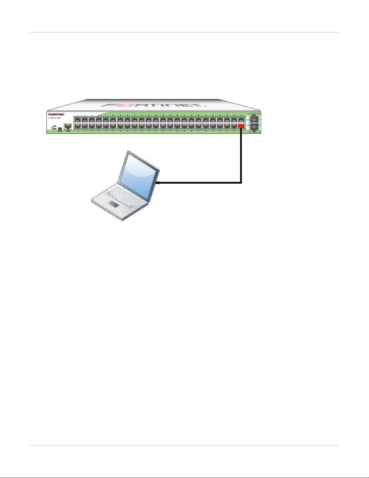
Port 48 used as an
inbound management interface
Example 1: Port 48 as an inbound management interface
In this example, a physical port is used as an inbound management interface. Also, the FortiSwitch in the
example has no default VLAN configured to connect its internal interface to any physical port.
Using Port 48 of a FortiSwitch-448B unit
Syntax
config system interface
edit internal
set type physical
next
edit mgmt-vlan
set ip 10.105.142.22 255.255.255.0
set allowaccess ping https ssh
set interface "internal"
set vlanid 4090
next
end
config switch interface
edit port48
set native-vlan 4090
set stp-state disabled
next
edit uplink1
next
edit uplink2
next
edit internal
set native-vlan 4095
set allowed-vlans 4090
set stp-state disabled
end
end
13
FortiSwitchOS-3.2.0
Page 14
Management Ports
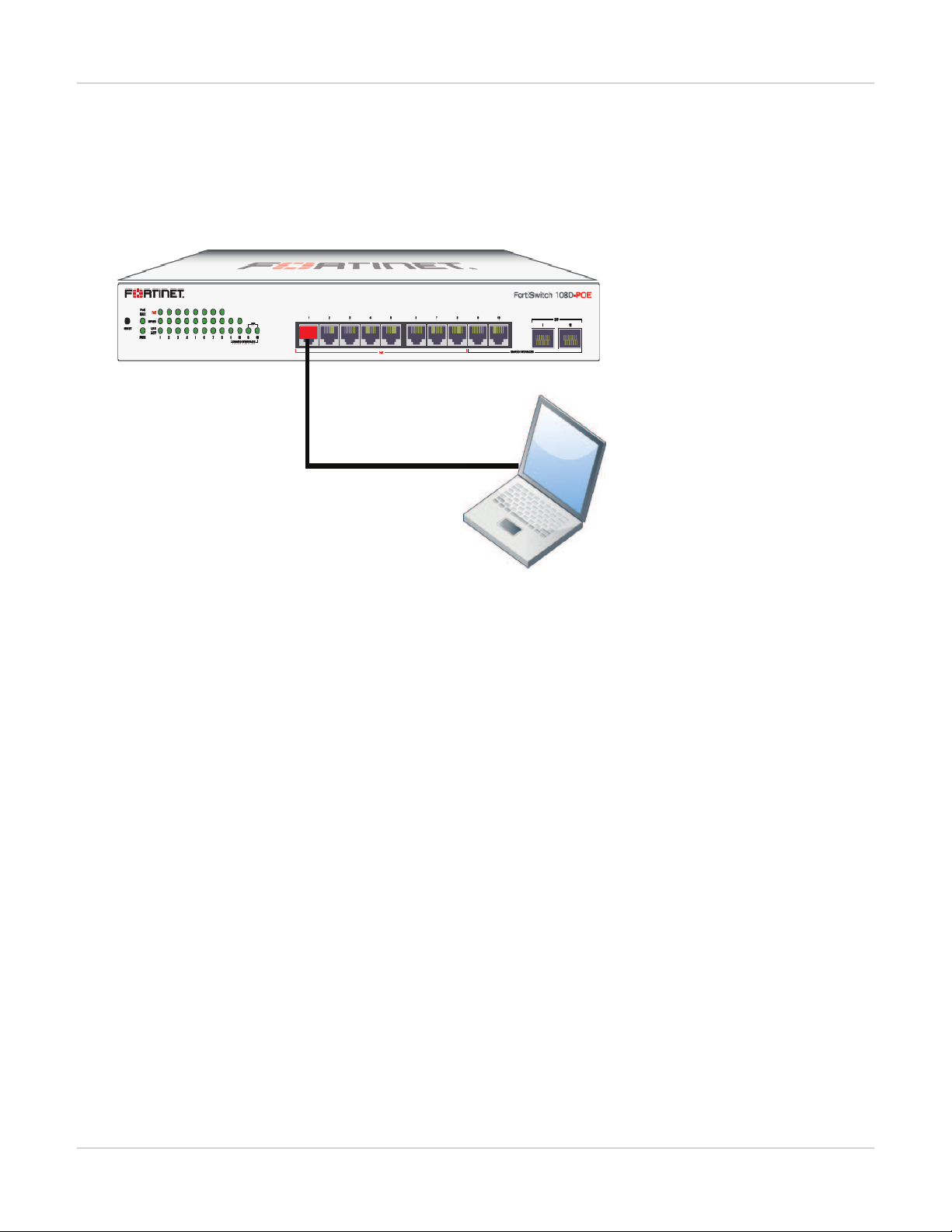
Port 1 (part of the internal interface)
used as an inband management interface
Example 2: Internal interface as an inbound management interface
In this example, the internal interface is used as an inbound management interface. Also, the FortiSwitch has a
default VLAN across all physical ports and its internal port.
Using the internaI interface of a FortiSwitch-108D-POE
Syntax
config system interface
edit internal
set ip 192.168.1.99 255.255.255.0
set allowaccess ping https http ssh
set type physical
end
end
Example 3: WAN interface as an inbound management port
In this example, the WAN interface is used as an inbound management port.
14 FortiSwitchOS-3.2.0
Page 15
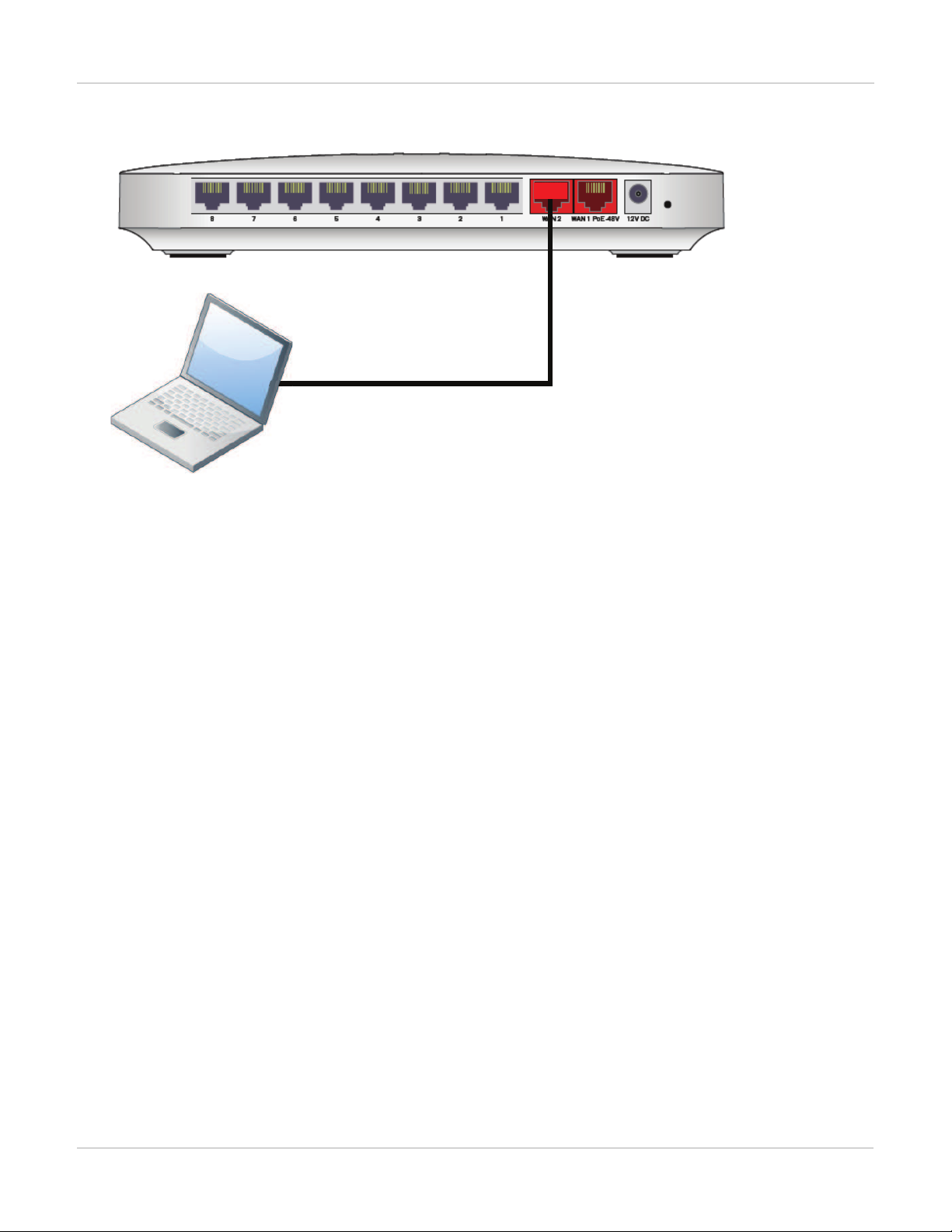
WAN interface of a FortiSwitch-28C
WAN 2 port used as an
inbound management port
Management Ports
Syntax
config system interface
edit wan2
set ip 10.105.142.10 255.255.255.0
set allowaccess ping https ssh
set type physical
next
edit wan1
set mode dhcp
set allowaccess ping https ssh
set type physical
set defaultgw enable
next
edit internal
set type physical
end
end
Example 4: Out of band management interface
In the example, an out of band management interface is used as the dedicated management port.
15
FortiSwitchOS-3.2.0
Page 16
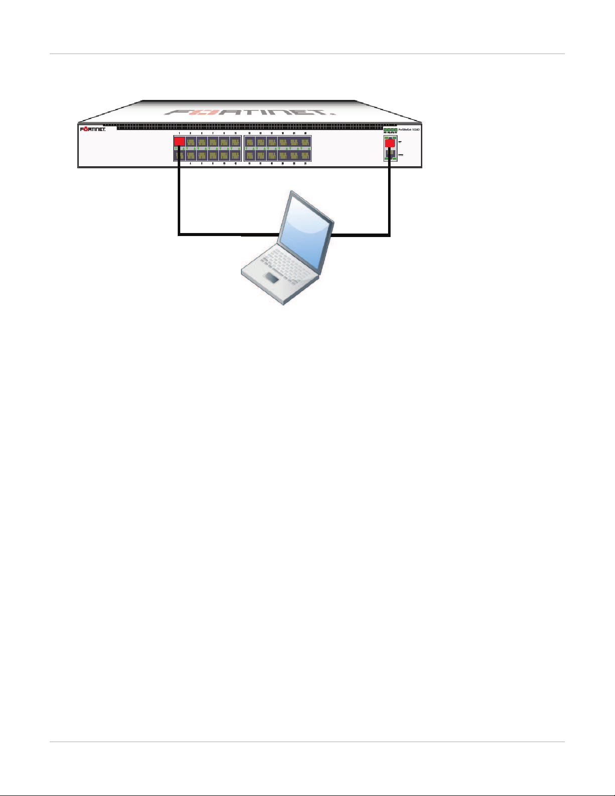
Out of band management on a FortiSwitch-1024D
Port 1 used as an
Ethernet data port
Dedicated
MGMT port
Syntax
Management Ports
config system interface
edit mgmt
set ip 10.105.142.19 255.255.255.0
set allowaccess ping https http ssh snmp telnet
set type physical
next
edit internal
set type physical
end
end
Configuring Static Routing for the Internal Management Port
Using the CLI:
config router static
edit 1
set device <internal>
set default gateway
set gateway 192.168.0.10
end
end
16 FortiSwitchOS-3.2.0
Page 17

Physical Port Settings
Physical Port Settings
This chapter covers features that are associated with FortiSwitch physical ports.
Diagnostic Monitoring Interface (DMI) Module Status
DMI is only supported on the following models: FortiSwitch-1024D, FortiSwitch-1048D, and FortiSwitch3032D.
The FortiSwitch-3032D also supports a 40G DMI.
DMI module status can be viewed using the command get switch modules. This allows you to display one of
the following:
l Module details (detail)
l Eeprom contents (eeprom)
l Module limits (limit)
l Module status (status)
l Summary information of all a port’s modules (summary)
Below is an example output for the command switch modules detail:
Port(port38)
identifier SFP/SFP+
connector LC
transceiver 10G Base-SR
encoding 64B/66B
Length Decode Common
length_smf_1km N/A
length_cable N/A
SFP Specific
length_smf_100m N/A
length_50um_om2 80 meter
length_62um_om1 30 meter
length_50um_om3 150 meter
vendor FINISAR CORP.
vendor_oid 0x009065
vendor_pn FTLX8572D3BCL
vendor_rev A
vendor_sn UDK050K
manuf_date 02/20/2009
17
FortiSwitchOS-3.2.0
Page 18

Physical Port Settings
Auto-Module Speed Detection
When you enable auto-module speed detection, the system reads information from the module, and sets the port
speed to the maximum speed that is advertised by the module. If there is a problem reading from the module, the
system sets the default speed (the default value is platform-specific).
When auto-module sets the speed, the system creates a log entry noting the speed that was set.
Enabling Auto-Module speed detection on a Port
config switch physical-port
edit <port>
set speed auto-module
end
end
Viewing Auto-Module Configuration
Display the status of Auto-Module using following commands
FS # config switch physical-port
FS (physical-port) # edit port47
FS(port47) # show
config switch physical-port
edit "port47"
set max-frame-size 16360
set speed 10000full
next
end
FS(port47) # get
name : port47
description : (null)
flow-control : both
link-status : down
max-frame-size : 16360
port-index : 47
speed : 10000full
status : up
Link-Layer Discovery Protocol
The Link Layer Discovery Protocol (LLDP) is a vendor-neutral Layer 2 protocol that enables devices on a Layer 2
segment to discover information about each other.
The switch will multicast LLDPpackets to advertise its identity and capabilities, and the switch receives the
equivalent information from adjacent layer 2 peers.
LLDP transmission is configured per port. By default LLDPtransmission is disabled.
18 FortiSwitchOS-3.2.0
Page 19

Enabling LLDP on a Port
config switch physical-port
edit <port>
set lldp-transmit [ enable | disable ]
next
end
Viewing LLDP Configuration
Use the following command to display the LLDPerrors:
get switch lldp errors
LLDP errors:
Total memory allocation failures: 0
Total unrecognized TLVs: 0
Use the following commands to display the LLDP information about the Layer 2 peers for a specified port:
Physical Port Settings
get switch lldp (neighbors-summary | neighbors-detail) <port>
Power over Ethernet
This section contains information on using Power over Ethernet (PoE) with your FortiSwitch.
Power over Ethernet is only available on the following models:
FS-108D-POE, FS-224D-POE, FSR-112D-POE,
FortiSwitch-108D-POE, FortiSwitch-124D-POE, FortiSwitch-224D-POE, and FortiSwitch-324BPOE.
Enabling PoE on a Port
config switch physical-port
edit <port>
set poe-status enable
end
end
Determining the PoE Power Capacity
To determine the PoE power capacity, use the following command:
get switch poe inline
19
FortiSwitchOS-3.2.0
Page 20

Reset the PoE Power on a Port
To reset the PoE power on a port, use the following command:
execute poe-reset <port>
Physical Port Settings
20 FortiSwitchOS-3.2.0
Page 21

Spanning Tree Protocol
Spanning Tree Protocol
Spanning tree protocol is a link-management protocol that ensures a loop-free Layer 2 network topology.
FortiSwitch supports the Multiple Spanning Tree Protocol (MSTP), which is defined in the IEEE 802.1Q standard.
MSTP Overview and terminology
MSTPsupports multiple spanning tree instances, where each instance carries traffic for one or more VLANs (the
mapping of VLANs to instances is configurable).
MSTP is backward-compatible with STPand RSTP. A given Layer 2 network may contain switches that are
running MSTP, STPor RSTP.
MSTPis built on RSTP, so it provides fast recovery from network faults and fast convergence times.
Regions
A region is a set of interconnected switches that have the same MSTconfiguration (region name, MSTrevision
number and VLAN-to-instance mapping). A network may have any number of regions. Regions are independent
of each other (VLAN-to-instance mapping is different in each region).
FortiSwitch supports 15 MST instances in a region. Multiple VLANs can be mapped to each MSTinstance. Each
switch in the region must have the identical mapping of VLANs to instances.
The MSTregion acts like a single bridge to adjacent MSTregions and to non-MST STPprotocols.
IST
Instance 0 is a special instance, called the IST. ISTis a spanning tree that connects all of the MST switches in a
region. All VLANs are assigned to the IST.
ISTis the only instance that exchanges BPDUs. The MSTPBPDUcontains information for each MSTPinstance
(captured in an M-record). The M-records are added to the end of a regular RSTPBPDU. This allows MSTP
region to inter-operate with an RSTPswitch.
CST
The Common Spanning Tree (CST)interconnects the MSTregions and all instances of STP or RSTP that are
running in the network.
Hop Count and Message Age
MST does not use the BPDUmessage age within a region. The message-age and maximum-age fields in the
BPDUare propagated unchanged within the region.
21
FortiSwitchOS-3.2.0
Page 22

Spanning Tree Protocol
Within the region, a hop-count mechansim is used to age out the BPDU. The ISTroot sends out BPDUs with hop
count set to Maximum hops. The hop count is decremented each time the BPDUis forwarded. If the hop count
reaches zero, the switch discards the BPDUand ages out the information on the receiving port.
MSTPconfiguration
Configuration consist of two steps:
l configure STPsettings that are common to all MSTinstances.
l configure settings that are specific to each MST instance.
Configuring STP settings
Some STPsettings (region name and MST revision number) are common to all MST instances. Also, protocol
timers are common to all instances, because only the ISTsends out BPDUs.
Using the web-based manager:
1. Go to Switch > STP > Settings
2. Update the settings as described in the following table
3. Click Apply to save the settings.
Settings Guidelines
Enable Enables MSTP for this switch.
Name
Region name. All switches in the MSTregion must have the identical
name.
Revision The MSTPrevision number. All switches in the region must have the same
revision number. Range of values is 0 - 65535
Default value is 0.
Hello time is how often (in seconds) that the switch sends out a BPDU.
Hello-Time
Range of values is 1 to 10.
Default value is 2.
Forward-Time Forward time is how long (in seconds) a port will spend in listening and
learning state before transitioning to forwarding state.
Range of values is 4 to 30.
Default value is 15.
22 FortiSwitchOS-3.2.0
Page 23

Spanning Tree Protocol
Settings Guidelines
The maximum age before the switch considers the received
BPDUinformation on a port to be expired. Max-age is used when inter-
Max-Age
Max-Hops Maximum hops is used inside the MSTregion. Hop count is decremented
working with switches outside the region.
Range of values is 6 to 40.
Default value is 20.
each time the BPDUis forwarded. If max-hops reaches zero, the switch discards the BPDUand ages out the information on the receiving port.
Range of values is 1 to 40.
Default value is 20.
Using the CLI:
config switch stp settings
set forward-time <4 - 30>
set hello-time <1 - 10>
set max-age <6 - 40>
set max-hops <1 - 40>
set name <region name>
set revision <0 - x>
set status {enable | disable}
end
Configuring an MSTinstance
STPtopology is unique for each MSTinstance in the region. You can configure a different bridge priority and port
parameters for each instance.
Using the web-based manager:
1. Go to Switch > STP > Instance
2. Create a new MSTinstance, or select an existing instance to edit.
3. Update the instance parameters as described in the following table.
4. Click Apply to save the settings.
23
FortiSwitchOS-3.2.0
Page 24

Spanning Tree Protocol
Settings Guidelines
ID Instance ID. Range is 1 - 15.
Priority is a component of bridge ID. The switch with the lowest bridge ID
becomes the root switch for this MST instance.
Priority
Allowed values: 0, 4096, 8192, 12288, 16384, 20480, 24576, 28672,
32768, 36864, 40960, 45056, 49152, 53248, 57344, and 61440
Default value is 32768
VLANRange The VLANs that map to this MST instance. You can specify individual
VLANnumbers, or a range of numbers.
Note: do not assign any VLANto more than one MSTinstance.
Each VLANnumber is in the range 1-4094
Port Configuration
Name Port that will participate in this MSTinstance.
The switch uses port cost to select designated ports. Port cost is added to
the received PBDUroot cost in any BPDU sent on this port.
A lower value is preferred. The range of values is 1 to 200,000,000.
Cost
Default value depends on the interface speed:
- 10 Gigabit Ethernet: 2,000
- Gigabit Ethernet: 20,000
- Fast Ethernet: 200,000
- Ethernet: 2,000,000
Priority The switch uses port priority to choose among ports of the same cost. The
port with the lowest priority is put into forwarding state. The valid values
are: 0, 32, 64, 96, 128, 160, 192, and 224.
Default value : 128
Using the CLI:
config switch stp instance
edit <instance number>
set priority <>
config stp-port
edit <port name>
set cost <>
set priority <>
next
set vlan-range <vlan range>
end
24 FortiSwitchOS-3.2.0
Page 25

Spanning Tree Protocol
Example:
config switch stp instance
edit "1"
set priority 8192
config stp-port
edit "port18"
set cost 0
set priority 128
next
edit "port19"
set cost 0
set priority 128
next
end
set vlan-range 5 7 11-20
end
Interactions outside of the MSTP Region
Aboundary port on an MSTswitch is a port that receives an STP(version 0) BPDU or an RSTP(version 2) BPDU,
or a PBDU from a different MST region.
If the port receives a version 0 BPDU, it will only send version 0 BPDUs on that port. Otherwise, it will send
version 3 (MST) BPDUs, since the RSTPswitch will read this as an RSTP BPDU.
Viewing the MSTPConfiguration
In order to view the MSTPconfiguration details, use the following commands:
get switch stp instance
get switch stp settings
Use the following commands to display information about the MSTPinstances in the network:
diagnose stp instance list
diagnose stp vlan list
diagnose stp mst-config list
25
FortiSwitchOS-3.2.0
Page 26

VLANTagging
FortiSwitch ports will process tagged and untagged Ethernet frames. Untagged frames do not carry any
VLANinformation.
Tagged frames include an additional header (the 802.1Q header) after the Source MAC address. This header
includes a VLANID.This allows the VLANvalue to be transmitted between switches.
VLANTagging
The FortiSwitch provides port parameters to configure and manage VLAN tagging.
Native VLAN
You can configure a native VLANfor each port. The native VLAN is like a default VLANfor untagged incoming
packets. Outgoing packets for the native VLAN are sent as untagged frames.
The native VLANis assigned to any untagged packet arriving at an ingress port.
At an egress port, if the packet tag matches the native VLAN, the packet is sent out without the VLANheader.
Allowed VLANList
The Allowed VLANlist for each port specifies the VLAN tag values for which the port can transmit or receive
packets.
For a tagged packet arriving at an ingress port, the tag value must match a VLANon the Allowed VLANlist. The
native VLANis NOTan allowed value for an incoming tagged packet.
At an egress port, the packet tag must match the native VLAN or a VLANon the Allowed VLANlist.
26 FortiSwitchOS-3.2.0
Page 27

Packet Processing
Ingress processing ensures that the port accepts only packets with allowed VLANvalues (untagged packets are
assigned the native VLAN, which is implicitly allowed). At this point, all packets are now tagged with a valid VLAN.
The packet is sent to each egress port that can send the packet (because the packet tag value matches the native
VLANor an Allowed VLAN on the port).
Ingress Port
Untagged packet
l packet is tagged with the native VLAN and allowed to proceed
l the Allowed VLAN list is ignored
Tagged packet
l tag VLANvalue must match an Allowed VLAN (which excludes the native VLAN)
l packet keeps the VLANtag and is allowed to proceed
VLANTagging
Egress Port
All packets that arrive at an egress port are tagged packets.
If the packet tag value is on the Allowed VLAN list, the packet is sent out with the existing tag.
if the packet tag value is the native VLAN, the tag is stripped and then the packet is sent out.
Otherwise the packet is dropped.
27
FortiSwitchOS-3.2.0
Page 28

Example 1
Example flows for tagged and untagged packets.
VLANTagging
Purple flow:
An untagged packet arriving at Port3 is assigned VLAN 100 (the native VLAN), and flows to all egress ports that
will send VLAN100 (Port1 and Port4).
A tagged packet (VLAN100) arriving at Port4 is allowed (VLAN100 is allowed). The packet is sent out from Port1
and Port3. On Port3, VLAN 100 is the native VLAN, so the packet is sent without a VLANtag.
Blue flow:
An untagged packet arriving at Port 4 is assigned VLAN 300 (the native VLAN). Then it flows out all ports that will
send Vlan300 (Port 3).
A tagged packet (VLAN300) arriving at Port3 is allowed. The packet is sent to egress from Port4. VLAN 300 is the
native VLAN on Port4, so the packet is sent without a VLANtag.
28 FortiSwitchOS-3.2.0
Page 29

Example 2
Example of invalid tagged VLAN.
VLANTagging
Green flow:
Between Port1 and Port2, packets are assigned to VLAN1 at ingress, and then the tag is removed at egress.
Blue flow:
Incoming on Port 3, a tagged packet with VLANvalue 100 is not allowed, because 100 is the native VLAN.
29
FortiSwitchOS-3.2.0
Page 30

Layer 2 Interfaces
This chapter provides information about configuring FortiSwitch layer 2 interfaces.
Configuring Switched Interfaces
Default configuration will suffice for regular switch ports. The default VLANis set to 1, STPis enabled, and all
other optional capabilities are disabled.
You can configure optional capabilities such as Loop Guard, IEEE 802.1x authentication, and Private VLAN.
These capabilities are covered in subsequent sections of this document.
Using the web-based manager:
1. Go to Switch > Interface > Interface
2. Select the port to update and click Edit.
3. Enter a new value for native VLAN.
Using the CLI:
config switch interface
edit <port>
set native-vlan <vlan>
set allowed-vlans <vlan> [<vlan>] [<vlan> - <vlan>]
set stp-state {enabled | disabled}
set edge-port {enabled | disabled}
Viewing Interface Configuration
Display port configuration using following command:
show switch interface <port>
Display port settings using following command:
config switch interface
edit <port>
get
Fortinet Loop Guard
A loop in a layer 2 network results in broadcast storms that have far-reaching and unwanted effects. Fortinet Loop
Guard helps to prevent loops. When Loop Guard is enabled on a switch port, the port monitors its subtending
network for any downstream loops. If a port detects a loop,the system takes the port out of service to protect the
overall network.
30 FortiSwitchOS-3.2.0
Page 31

Layer 2 Interfaces
The loop guard feature is designed to work in concert with STP rather than as a replacement for STP. Each port
that has loop guard enabled will periodically broadcast Loop Guard Data Packets (LGDP) packets to its network.
If a broadcast packet sent out on a port is subsequently received by the same port, a loop exists downstream.
The system takes the port out of service. The port returns to service after a configured timeout duration. If the
timeout value is zero, you must manually reset the port.
By default, Loop Guard is disabled on all ports, and the timeout is set to Zero.
Configuring Loop Guard
Using the CLI:
config switch interface
edit port <number>
set loop-guard <enabled|disabled>
set loop-guard-timeout <integer>
Use the following command to reset a port that detected a loop:
execute loop-guard reset <port>
Viewing Loop Guard Configuration
Display the Loop Guard configuration for a port using following command:
config switch interface <port>
show
31
FortiSwitchOS-3.2.0
Page 32

Link Aggregation Groups
This chapter provides information on how to configure a Link Aggregation Group (LAG). For LAGcontrol,
FortiSwitch supports the industry-standard Link Aggregation Control Protocol (LACP).
FortlSwitch supports LACPprotocol in active and passive modes.
In active mode, you can optionally specify the mininum and maximum number of active members in a trunk
group.
FortlSwitch supports flap guard protection for switch ports in a LAG.
Configuring the Trunk and LAG Ports
It is important to configure the trunk to prevent loops.
Using the web-based manager:
1.
Go to Switch > Port > Trunk and select Create Trunk.
2. Give the trunk an appropriate name.
3.
Set Mode to either static, lacp-active or lacp-passive.
4.
Add the required ports to the Members list.
5.
Select OK.
Using the CLI:
config switch trunk
edit <trunk name>
set description <description_string>
set members <ports>
set mode {lacp-active | lacp-passive | static}
set member-withdrawal-behaviour {block | forward}
set lacp-speed {fast | slow}
set bundle [enable|disable]
set min_bundle <integer>
set max_bundle <integer>
set port-selection-criteria
{src-ip | src-mac | dst-ip |dst-mac | src-dst-ip |src-dst-mac}
end
end
Example Configuration
The following is an example CLI configurations for trunk/LAG ports:
32 FortiSwitchOS-3.2.0
Page 33

Trunk/LAG ports
1. Configure the trunk 1 interface and assign member ports as a LAG group:
config switch trunk
edit trunk1
set members "port1" "port2" "port3"
set description test
set mode lacp-passive
set port-selection criteria src-dst-ip
end
end
Link Aggregation Groups
2. Configure the switch ports to have native vlan assignments and allow those vlans on the port that will be the uplink
port:
config switch interface
edit port 1
set native-vlan 1
next
edit port 2
set native-vlan 2
next
edit port 3
set native-vlan 3
next
edit port 4
set native-vlan 4
set allowed vlans 1 2 3
next
edit port 5
set native-vlan 5
set allowed-vlans 1 2 3
end
end
3. Configure the trunk 2 interface and assign member ports as a LAG group:
config switch trunk
edit trunk2
set members "port4" "port5"
set description test
set mode lacp-passive
set port-selection criteria src-dst-ip
end
33
FortiSwitchOS-3.2.0
Page 34

end
Viewing the Configured Trunk
In order to see the details of a configured trunk, use the following command:
diagnose switch trunk list
Link Aggregation Groups
34 FortiSwitchOS-3.2.0
Page 35

Port Mirroring
This chapter contains information on how to configure layer 2 port mirroring.
Configuring a Port Mirror
Using the web-based manager:
1.
Go to Switch > Port > Mirror.
2. Enter a name for the mirror.
3.
Set the Status Enable check box to set the mirror to active.
4. Select a Destination Port.
5. Select available ports to be used for Ingress Monitoring and Egress Monitoring.
6.
Enable the Packet switching functionality when mirroring option if the destination port is not a dedicated
port. For example, enable this option if you connect a laptop to the switch and you are running a packet sniffer
along with the management GUIon the laptop.
Port Mirroring
Using the CLI:
config switch mirror
edit "m1"
set dst "port5"
set src-egress "port2" "port3"
set src-ingress "port2" "port4"
set status active
set switching-packet enable
end
Multiple Mirror Destination Ports (MTP)
With some FortiSwitch models, you can configure multiple mirror destination ports. However, note the following
guidelines and restrictions:
l Always set the destination port before setting the src-ingress or src-egress ports
l Any port configured as a src-ingress or src-egress port in one mirror cannot be configured as a destination port in
another mirror.
l For switch models FS-1024D, FS-1048D, and FS--3032D:
l You can configure a maximum of four mirror destination ports.
l You can configure a maximum of four ingress/egress ports.
l The same ingress/egress port can be mirrored to more than one destination port.
l For switch models FS-108D-POE and FS-224D-POE:
l You can configure up to seven port mirrors, each with a different destination port.
35
FortiSwitchOS-3.2.0
Page 36

Port Mirroring
l There is no limit on the number of ingress or egress ports.
l An ingress or egress port cannot be mirrored to more than one destination port.
The above restrictions apply to active port mirrors. If you try to activate an invalid port mirror configuration, the
system will display the Insufficient resources!! error message.
The following example configuration is valid for FortiSwitch--3032D:
config switch mirror
edit "m1"
set dst "port16"
set status active
set src-ingress "port3" "port5" "port7"
next
edit "m2"
set dst "port22"
set status active
set src-ingress "port3" "port5"
next
edit "m3"
set dst "port1"
set status active
set src-egress "port3"
next
edit "m4"
set dst "port2"
set status active
set src-egress "port3"
end
(The above configuration includes three ingress ports, one egress port, and four destination ports. The port3
ingress and egress ports are mirrored to multiple destinations).
The following example configuration is valid for FortiSwitch-224D-POE:
config switch mirror
edit "m1"
set dst "port1"
set status active
set src-ingress "port2" "port7"
next
edit "m2"
set dst "port5"
set status active
set src-egress "port2"
next
edit "m3"
set dst "port3"
set status active
set src-ingress "port6"
next
edit "m4"
set dst "port4"
set status active
set src-egress "port6" "port8"
end
36 FortiSwitchOS-3.2.0
Page 37

Port Mirroring
(The above configuration includes three ingress ports, three egress ports and four destination ports. Each ingress
and egress port is mirrored to only one destination port).
37
FortiSwitchOS-3.2.0
Page 38

Private VLANs
This chapter contains information on the creation and management of private virtual local area networks
(VLANs).
About Private VLANs
A Private VLAN divides the original VLAN, now called the Primary VLAN, into sub-VLANs (Secondary VLANs),
while keeping the existing IP subnet and layer 3 configuration. Unlike a regular VLAN, which is a single broadcast
domain, private VLANs partitions one broadcast domain into multiple smaller broadcast subdomains.
After a Private VLAN is configured, the Primary VLAN is used to forward frames downstream to all Secondary
VLANs.
There are two main types of Secondary VLAN:
l
Isolated: Any switch ports associated with an Isolated VLAN can reach the primary VLAN, but not any other
Secondary VLAN. In addition, hosts associated with the same Isolated VLAN cannot reach each other. Only one
Isolated VLAN is allowed in one Private VLAN domain.
l
Community: Any switch ports associated with a common community VLAN can communicate with each other and
with the primary VLAN but not with any other secondary VLAN. There can be multiple distinct community VLANs
within one Private VLAN domain.
There are mainly two types of ports in a Private VLAN: Promiscuous port (P-Port) and Host port.
l
Promiscuous port (P-Port): The switch port connects to a router, firewall or other common gateway device. This
port can communicate with anything else connected to the primary or any secondary VLAN. In other words, it is a
type of a port that is allowed to send and receive frames from any other port on the VLAN.
l
Host Ports further divides in two types – Isolated port (I-Port) and Community port (C-port).
l
Isolated Port (I-Port): Connects to the regular host that resides on isolated VLAN. This port communicates
only with P-Ports.
l
Community Port (C-Port): Connects to the regular host that resides on community VLAN. This port
communicates with P-Ports and ports on the same community VLAN.
Private VLAN Example
1. Enabling a Private VLAN:
config switch vlan
edit 1000
set private-vlan enable
set isolated-vlan 101
set community-vlans 200-210
end
end
2. Configuring the Private VLAN ports:
config switch interface
edit "port2"
set private-vlan promiscuous
38 FortiSwitchOS-3.2.0
Page 39

set primary-vlan 1000
next
edit "port3"
set private-vlan sub-vlan
set primary-vlan 1000
set sub-vlan 200
next
edit "port7"
set private-vlan sub-vlan
set primary-vlan 1000
set sub-vlan 101
next
edit "port19"
set private-vlan promiscuous
set primary-vlan 1000
next
edit "port20"
set private-vlan sub-vlan
set primary-vlan 1000
set sub-vlan 101
next
edit "port21"
set private-vlan sub-vlan
set primary-vlan 1000
set sub-vlan 101
end
end
Private VLANs
Configuring SNMP Access
1. Ensure that the management vlan has SNMP added to the access-profiles:
config system interface
edit <name>
set ip <ip_address>
set allowaccess <access_types>
set interface <name>
end
end
2. Ensure that a SNMP community is created (with host configured):
config system snmp community
edit <id>
config hosts
edit <id>
end
set name <name>
end
end
39
FortiSwitchOS-3.2.0
Page 40

Layer 3 Interfaces
Layer 3 Interfaces
This chapter provides information about configuring Layer 3 interfaces. FortiSwitch supports Switched
VirtualInterfaces (SVI) and Routed Ports. These interface types are described in detail below.
Switched VirtualInterfaces
Switched Virtual Interface (or SVI) is a logical interface that is associated with a VLAN. You can assign an IP
address to the SVIinterface to enable routing between VLANs. For example, we may use SVIs to route between
two different VLANs connected to a switch (no need to connect through a L3 router).
The SVIattaches to the “internal" interface in the switch. An SVI supports routing and switching protocols.
Configuring a Switched Virtual Interface
Using the CLI:
Set the Allowed VLAN list on the internal interface. Include all of the VLANs for ports that route through this SVI.
config switch interface
edit internal
set allowed-vlans <vlan list>
end
Create a system interface. Give it an IPsubnet and an associated VLAN.
config system interface
edit <sytem interface name>
set ip <IP address and mask>
set vlanid <vlan>
set interface internal
set allowacess ping ssh telnet
Configure a static route:
config router static
edit 1
set dst <IP subnet and mask>
set device <sytem interface name>
Example SVIConfiguration
The following is an example CLI configurations for SVI static routing.
In this configuration, Server-1 is connected to switch Port1 and Server-2 is connected to switch Port2. Their IP
and MAC address are show in the diagram. Port1 is a member of VLAN 4000 and Port2 is a member of VLAN 2.
For Server-1, Port1 is the gateway and for Server-2, port2 is the gateway.
(Note: For simplicity, assume that both port1 and port are on same switch)
40 FortiSwitchOS-3.2.0
Page 41

Layer 3 Interfaces
1. Configure Native VLANs for Port1 & Port2. Also configure “internal” interface to allow the native VLANs for Port1
and Port2.:
config switch interface
edit port1
set native-vlan 4000
edit port2
set native-vlan 2
edit internal
set allowed-vlans 2, 4000
end
2. Create L3 system interfaces that correspond to port 1 (VLAN4000) and Port 2 (VLAN2):
config system interface
edit vlan4000
set ip 192.168.11.1/24
set vlanid 4000
set interface internal
set allowacess ping ssh telnet
next
edit vlan2
set ip 192.168.10.1/24
set vlanid 2
set interface internal
set allowacess ping ssh telnet
end
3. Configure static routes, so that the switch will know how to route between the two VLANs:
config router static
edit 1
set dst 192.168.10.0/24
set device vlan2
next
edit 2
set dst 192.168.11.0/24
set device vlan4000
end
Viewing SVIConfiguration
Display the status of SVIconfiguration using following command:
show system interface [ <sytem interface name> ]
Routed Interfaces
A routed port is a physical port on a switch that acts like a port on a router. It supports all routing protocols and
terminates Layer 2 completely. It does not support VLAN sub-interfaces and it is not associated with a VLAN. A
routed port typically connects to either a server or a router (a Layer 3 device).
The routed port is associated with a subnet.
The main reason to use a routed interface is to simplify the network topology.
41
FortiSwitchOS-3.2.0
Page 42

Configuring a Routed Interface
Using the CLI:
Set the Allowed VLAN list on the internal interface. Include the VLANs of the routed ports.
config switch interface
edit internal
set allowed-vlans <vlan list>
end
Create a Layer 3 virtual interface corresponding to the physical port:
config system interface
edit <rvi name>
set switch-members <port> <port> ...
next
edit <virtual device name>
set vlanid <vlan>
set ip <ip subnet> <mask>
set interface <rvi name>
set allowaccess ping telnet
Layer 3 Interfaces
Configure static routes, so that the switch will know how to route between VLANs:
config router static
edit 2
set device <virtual device name>
set dst <ip subnet>
Example Routed Port Configuration
The following is an example CLI configuration for Routed Port static routing.
In this configuration, we configure Port2 and Port6 as a Routed Port. We created interface I-RED and I-GREEN
as RVI interface. Remainder of the ports in the switch are normal Layer 2 ports.
1. Configure Native VLANs for Port2, Port6 and Port9. Also configure “internal” interface to allow native VLANs for
Port2, Port6 and Port9.:
config switch interface
edit port2
set native-vlan 10
edit port6
set native-vlan 20
edit port9
set native-vlan 30
edit internal
set allowed-vlans 10,20,30
end
2. Create L3 virtual interfaces corresponding to the physical ports:
config system interface
edit "i-red"
set switch-members "port2"
next
42 FortiSwitchOS-3.2.0
Page 43

edit "i-green"
set switch-members "port6"
next
edit "rVan10"
set vlanid 10
set ip 1.1.3.1 255.255.255.0
set interface "i-red"
set allowaccess ping telnet
next
edit "gVlan20"
set vlanid 20
set ip 172.168.13.1 255.255.255.0
set allowaccess ping telnet
set interface "i-green"
next
edit "b-vlan30"
set vlanid 30
set ip 192.168.13.1 255.255.255.0
set allowaccess ping telnet
set interface internal
end
3. Configure static routes, so that the switch will know how to route between the two VLANs:
config router static
edit 1
set device "mgmt"
set gateway 10.105.0.1
next
edit 2
set device "rVlan10"
set dst 1.1.3.0/24
next
edit 3
set device "gVlan20"
set dst 172.168.13.0/24
next
edit 4
set device "b-vlan30"
set dst 192.168.13.0/24
end
Layer 3 Interfaces
Viewing Routed Port Configuration
Display the status of RVIconfiguration using following commands
show system interface [ <sytem interface name> ]
Equal Cost Multi-Path (ECMP) Routing
Equal Cost Multi-Path (ECMP) is a forwarding mechanism that enablee load-sharing of traffic to multiple paths of
equal cost.
43
FortiSwitchOS-3.2.0
Page 44

Layer 3 Interfaces
An ECMP set is formed when the routing table contains multiple next-hop address for the same destination with
equal cost.
Routes of equal cost have the same preference and metric value. If there is an ECMP set for an active route, the
switch uses a hash algorithm to choose one of the next-hop addresses.
As input to the hash, the switch uses one or more of the following fields in the packet to be routed: Source IP,
Destination IP, or Input Port.
Configuring ECMP
The switch will automatically use ECMP to choose between equal-cost routes.
As input to the hash, you can configure the switch to use one or more of the following fields in the packet to be
routed: Source IP, Destination IP, or Input Port.
This configuration value is system-wide. Source IP is the default value.
Notes and Restrictions
Maximum of 8 alternative paths (i.e. ecmp path).
When you configure a static route with a gateway, the gateway must be in the same IPsubnet as the device.
Also, the destination subnet cannot be equal to any of device IP subnets in the system.
When you configure a static route without a gateway, the destination subnet be in the same IPsubnet as the
device.
Using the CLI:
config system setting
set v4-ecmp-mode [ source-ip-based ] [ dst-ip-based ] [ port-based ]
end
Example ECMPConfiguration
The following is an example CLI configuration for ECMP forwarding.
In this configuration, we configure Port2 and Port6 as routed ports. We create interfaces I-RED and I-GREEN as
RVI interface. The remaining ports in the switch are normal Layer 2 ports.
1. Configure Native VLANs for Port2, Port6 and Port9. Also configure “internal” interface to allow native VLANs for
Port2, Port6 and Port9.:
config switch interface
edit port2
set native-vlan 10
edit port6
set native-vlan 20
edit port9
set native-vlan 30
edit internal
set allowed-vlans 10,20,30
end
2. Configure system interfaces.:
config system interface
44 FortiSwitchOS-3.2.0
Page 45

edit "internal"
set type physical
next
edit "i-blue"
set ip 1.1.1.1 255.255.255.0
set allowaccess ping https http ssh snmp telnet
set vlanid 10
set interface internal
next
edit "i-red"
set ip 172.16.11.1 255.255.255.0
set allowaccess ping ssh telnet
set vlanid 20
set interface "internal"
next
edit "i-green"
set ip 172.168.13.1 255.255.255.0
set allowaccess ping https http ssh snmp telnet
set vlanid 30
set interface "internal"
next
end
Layer 3 Interfaces
3. Configure static routes.We are configuring multiple next hop gateway for the same network:
config router static
edit 1
set device "mgmt"
set gateway 10.105.0.1
next
edit 2
set device “i-red"
set dst 8.8.8.0/24
set gateway 172.16.11.2
next
edit 3
set device "i-green"
set dst 8.8.8.0/24
set gateway 172.168.13.2
next
Viewing ECMPConfiguration
Display the status of ECMPconfiguration using following commands
show system interface [ <sytem interface name> ]
Bidirectional Forwarding Detection
Bidirectional Forwarding Detection (BFD) is a point-to-point protocol to detect faults in the datapath between the
endpoints of an IETF-defined tunnel (such as IP, IP-in-IP, GRE, MPLSLSP/PW).
45
FortiSwitchOS-3.2.0
Page 46

Layer 3 Interfaces
BFDdefines Demand mode and Asynchronous mode operation. The FortiSwitch supports Asynchronous mode.
In this mode, the systems periodically send BFD Control packets to one another, and if a number of those
packets in a row are not received by the other system, the session is declared to be down.
BFD packets are transported using UDP/IP encapsulation and BFD control packets are identified using well
known UDP destination port 3784 (Note: BFD echo packets are identified using 3785).
BFD packets are not visible to the intermediate nodes and are generated and processed by the tunnel end
systems only.
Configuring BFD
Use the following steps to configure BFD:
1. Configure the following values in the system interface:
l
Enable BFD. Set to enable, or set to global to inherit the global configuration value.
l Desired min TXinterval. This is the minimum interval that the local system would like to use between
transmission of BFDcontrol packets. Value range is 1-100,000 ms. Default value is 1000.
l Required min RXinterval. This is the minimum interval that the local system can support between receipt
of BFDcontrol packets. If you set this value to zero, the remote system will not transmit BFDcontrol
packets. Value range is 1-100,000 ms.Default value is 1000.
l Detect multi. This is the detection time multiplier. The negotiated transmit interval multiplied by this value
is the Detection Time for the receiving system.
2. Enable BFD in the static router configuration:
Using the CLI:
config system interface
edit <system interface name>
set bfd [enable| disable | global]
set bfd–desired-min-tx <number of ms>
set bfd-required-min-rx <number of ms>
set bfd-detect-multi [1…50]
next
config router static
set bfd enable
Viewing BFD Configuration
Display the status of BFD sessions using following commands
get router info bfd neighbor [ <IP address of neighbor>]
OurAddr NeighAddr LD/RD State Int
192.168.15.2 192.168.15.1 1/4 UP vlan2000
192.168.16.2 192.168.16.1 2/2 UP vlan2001
Use the following command to display additional detail:
get router info bfd neighbor detail
46 FortiSwitchOS-3.2.0
Page 47

Layer 3 Interfaces
IP-MACBinding
Use IP-MACbinding to prevent ARPspoofing.
Port accepts a packet only if the source IPaddress and source MACaddress in the packet match an entry in the
IP-MACbinding table.
You can enable/disable IP-MACbinding for the whole switch, and you can override this global setting for each
port.
Configuring IP-MACBinding
Use the following steps to configure IP-MACBinding:
1. Configure switch ip-mac-binding global setting.
2. Create the IP-MACbindings. You can activate each binding individually.
3. Set each port to follow the global setting. You can also override the global setting for indivual ports by enabling or
disabling IP-MACbinding for the port.
Using the CLI:
config switch global
set ip-mac-binding [enable| disable]
config switch ip-mac-binding
edit 1
set ip <IP address and network mask>
set mac <MAC address>
set status (enable| disable)
next
end
config switch interface
edit <port>
set ip-mac-binding (enable| disable | global)
edit <trunk name>
set ip-mac-binding (enable| disable | global)
Notes
For a switch port, the default IP-MAC binding falue is disabled.
When you configure a trunk, the default is for the trunk to follow the global value. You can also explicitly enable or
disable IP-MACbinding for a trunk, as shown above.
When you add member ports to the trunk, all ports take on the trunk setting. If you later remove a port from the
trunk group, the port is reset to the default value (disabled).
No duplicate entries allowed in the mapping table.
Rules are disabled by default. You need to explicitly enable each rule.
Mapping table holds up to 1024 rules.
47
FortiSwitchOS-3.2.0
Page 48

Viewing IP-MACBinding Configuration
Display the status of IP-MACbinding using following command
show switch ip-mac-binding <entry number>
Layer 3 Interfaces
48 FortiSwitchOS-3.2.0
Page 49

802.1x Authentication
This chapter contains information about how to use IEEE 802.1x authentication on Fortinet switches.
About 802.1x
FortiSwitch supports IEEE 802.1x authentication to control network access. FortiSwitch implements port-based
and MAC-based access.
A supplicant connected to a port on the switch must be authenticated by a Radius/diameter server in order to gain
access to the network. The supplicant and the authentication server communicate via the switch using EAP
protocol.
With port-based authentication, any user on the authenticated port will have access to the network.
With MAC-based authentication, the switch saves the MAC address of the supplicant's device. The switch limits
network access to devices that have successfully been authenticated.
Authenticating with a RADIUS server
Using the CLI:
1. Creating a RADIUS user group:
config user radius
edit <name>
set server <address>
end
end
2. Creating a user group:
config user group
edit <name>
set member <list>
config match
edit 1
set group-name <name>
set server-name <name>
end
end
end
end
3. Configuring the switch interface for port-based 802.1x
config switch interface
edit <interface>
set security-mode 802.1X
set security-groups <name>
49 FortiSwitchOS-3.2.0
Page 50

end
end
4. Configuring the switch interface for MAC-based 802.1x
config switch interface
edit <interface>
set security-mode 802.1X-mac-base
set security-groups <name>
end
end
5. Configuring an STP instance
config switch stp instance
edit <name>
set priority <integer>
end
end
Using the web-based manager:
NOTE:Define the Radius server and remote user group using the CLI(steps 1 and 2 above).
1.
Go to Switch > Interface > Interface and select the port to update.
2.
Set Security Mode to either 802.1x or 802.1x-mac-based
3.
Select OK.
802.1x Authentication
Example Configuration
The following is an example configuration for a RADIUS user group, with the CLI syntax shown to create it.
1. Creating a RADIUS user group
config user radius
edit R1
set server “192.160.10.98”
next
end
2. Creating a user group
config user group
edit 802group
set member user1 R1
config match
edit 1
set group-name 802group
set server-name R1
end
end
end
end
50
FortiSwitchOS-3.2.0
Page 51

TACACS
This chapter contains information on using TACACS authetication with your FortiSwitch unit.
Administrative Accounts
Administrative, or admin, accounts allow access to various aspects of the FortiSwitch configuration. The level of
access is determined by the access profile used in the admin account.
Configuring an Access Profile for Admin Accounts
Using the web-based manager:
1.
Go to System > Admin > Admin Profile and select Create New.
2. Give the profile an appropriate name.
3.
Set Access Control as desired, choosing between None, Read Only, or Read-Write.
4.
Select OK.
Using the CLI:
config system accprofile
edit <name>
set admingrp {none | read | read-write}
set loggrp {none | read | read-write}
set netgrp {none | read | read-write}
set routegrp {none | read | read-write}
set sysgrp {none | read | read-write}
end
end
Configuring a TACACS Admin Account
Using the web-based manager:
1.
Go to System > Admin > Administrators and select Create New.
2. Give the administrator account an appropriate name.
3.
Set Type as Remote.
4.
Set User Group to a group for remote users.
5.
Enable Wildcard.
6.
Set Admin Profile to use the new profile.
7.
Select OK.
51 FortiSwitchOS-3.2.0
Page 52

Using the CLI:
config system admin
edit tacuser
set remote-auth enable
set wildcard enable
set remote-group <group>
set accprofile <profile>
end
end
User Accounts
User accounts can be used to identify a network user and determine what parts of the network the user is allowed
to access.
Configuring a User Account
config user tacacs+
edit <tacserver>
set authen-type {ascii | auto | chap | ms_chap | pap}
set authorization enable
set key <authorization_key>
set server <server>
end
end
TACACS
Configuring a User Group
config user group
edit <tacgroup>
set member <tacserver>
config match
edit 1
set server-name <server>
set group-name <group>
end
end
end
end
Example Configuration
The following is an example configuration of a TACACS user account, with the CLI syntax shown to create it:
1. Configuring a TACACS user account for login authentication:
config user tacacs+
edit tacserver
set authen-type ascii
set authorization enable
52
FortiSwitchOS-3.2.0
Page 53

set key temporary
set server tacacs_server
end
2. Configuring a TACACS user group:
config user group
edit tacgroup
set member tacserver
config match
edit 1
set server-name tacserver
set group-name tacgroup
end
end
end
end
3. Configuring a TACACs system admin user account:
config system admin
edit tacuser
set remote-auth enable
set wildcard enable
set remote-group tacgroup
set accprofile noaccess
end
end
TACACS
53 FortiSwitchOS-3.2.0
Page 54

Copyright© 2015 Fortinet, Inc. All rights reserved. F ortinet®, FortiGate®, FortiCare® and FortiGuard®, and certain other marks are registered trademarks of Fortinet,
Inc., in the U.S. and other jurisdictions, and other Fortinet names herein may also be registered and/or c ommon law trademarks of Fortinet. All other product or company
names may be trademarks of t heir respective owners. Performance and other metrics contained herein were attained in internal lab tests under ideal conditions, and
actual performance and other results may vary. Network variables, different network environments and other conditions may affect performance results. Nothing herein
represents any binding commitment by Fortinet, and Fortinet disclaims all warranties, whether express or implied, except to the extent Fortinet enters a binding written
contract, signed by Fortinet’s General Counsel, with a purchaser that expres sly warrants that the identified product will perf orm accordingto certain expressly-identified
performance metrics and, in such event, only the specific performance metrics expressly identified in such binding writt en c ontract shall be binding on Fortinet. For
absolute clarity, any such warranty will be limited to performance in the s ame ideal conditions as in Fortinet’s internal lab tests. In no event does Fortinet make any
commitment related to future deliverables, features, or development, and circums tances may change such that any forward-look ing statements herein are not accurate.
Fortinet disclaims in full any covenants, representations,and guarantees pursuant hereto, whether express or implied. Fortinet reserves the right to change, modify,
transfer, or ot herwise revise this publication without notice, andthe most current version of the publication s hall be applicable.
 Loading...