

Page 1
TM
FortiSwitch-5003A
System Guide
A detailed guide to the FortiSwitch-5003A system. This FortiSwitch-5003A System Guide describes the
FortiSwitch-5003A hardware features, how to install the FortiSwitch-5003A board in a FortiGate-5000 series chassis,
and how to configure the FortiSwitch-5003A system.
The most recent versions of this and all FortiGate-5000 series documents are available from the FortiGate-5000 page of
the Fortinet Technical Documentation web site (http://docs.forticare.com).
Visit http://support.fortinet.com to register your FortiSwitch-5003A system. By registering you can receive product
updates, technical support, and FortiGuard services.
FortiSwitch-5003A System Guide
Preliminary-01-30000-77803-20080917
Page 2

Warnings and cautions
!
!
Only trained and qualified personnel should be allowed to install or maintain FortiGate-5000 series
equipment. Read and comply with all warnings, cautions and notices in this document.
CAUTION: Risk of Explosion if Battery is replaced by an Incorrect Type. Dispose of Used Batteries According
to the Instructions.
Caution: You should be aware of the following cautions and warnings before installing FortiGate-5000 series
hardware
• Turning off all power switches may not turn off all power to the FortiGate-5000 series equipment. Some
circuitry in the FortiGate-5000 series equipment may continue to operate even though all power
switches are off. Follow all instructions in the procedures in this document for disconnecting
FortiGate-5000 series equipment from power sources, telecommunications links and networks before
installing, or removing FortiGate-5000 series components, or performing other maintenance tasks.
Failure to do following these instructions can result in personal injury or equipment damage.
• Install FortiGate-5000 series chassis at the lower positions of a rack to avoid making the rack top-heavy
and unstable.
• Do not insert metal objects or tools into open chassis slots.
• Electrostatic discharge (ESD) can damage FortiGate-5000 series equipment. Only perform the
procedures described in this document from an ESD workstation. If no such station is available, you
can provide some ESD protection by wearing an anti-static wrist strap and attaching it to an available
ESD connector such as the ESD sockets provided on FortiGate-5000 series chassis.
• Make sure all FortiGate-5000 series components have reliable grounding. Fortinet recommends direct
connections to the building ground.
• If you install a FortiGate-5000 series component in a closed or multi-unit rack assembly, the operating
ambient temperature of the rack environment may be greater than room ambient. Make sure the
operating ambient temperature does not exceed Fortinet’s maximum rated ambient temperature.
• Installing FortiGate-5000 series equipment in a rack should be such that the amount of airflow required
for safe operation of the equipment is not compromised.
• FortiGate-5000 series chassis should be installed by a qualified electrician.
• FortiGate-5000 series equipment shall be installed and connected to an electrical supply source in
accordance with the applicable codes and regulations for the location in which it is installed. Particular
attention shall be paid to use of correct wire type and size to comply with the applicable codes and
regulations for the installation / location. Connection of the supply wiring to the terminal block on the
equipment may be accomplished using Listed wire compression lugs, for example, Pressure Terminal
Connector made by Ideal Industries Inc. or equivalent which is suitable for AWG 10. Particular attention
shall be given to use of the appropriate compression tool specified by the compression lug
manufacturer, if one is specified.
FortiSwitch-5003A System Guide
01-30000-77803-20080917
Page 3

Contents
Contents
Warnings and cautions ..................................................................................... 2
FortiSwitch-5003A system ................................................ 5
Front panel LEDs and connectors ................................................................... 6
LEDs ............................................................................................................. 7
Base channel interfaces................................................................................ 8
Fabric channel interfaces .............................................................................. 9
Front panel connectors ............................................................................... 10
FortiSwitch-5003A configurations ................................................................. 10
Base and fabric gigabit switching within a chassis...................................... 10
Base and fabric 10-gigabit switching within a chassis ................................ 11
Layer-2 link aggregation and redundancy configurations ........................... 12
Hardware installation....................................................... 13
Setting the FortiSwitch-5003A configuration switch.................................... 13
FortiSwitch-5003A mounting components.................................................... 15
Inserting a FortiSwitch-5003A board ............................................................. 16
Removing a FortiSwitch-5003A board ........................................................... 18
Resetting a FortiSwitch-5003A board ............................................................ 20
Troubleshooting .............................................................................................. 20
FortiSwitch-5003A does not startup ............................................................ 20
Quick Configuration Guide ............................................. 21
Registering your Fortinet product ................................................................. 21
Factory default settings .................................................................................. 21
Basic configuration ......................................................................................... 22
Upgrading FortiSwitch-5003A firmware ........................................................ 23
Additional configuration ................................................................................. 23
For more information....................................................... 25
Fortinet documentation................................................................................... 25
Fortinet Tools and Documentation CD ........................................................ 25
Fortinet Knowledge Center ........................................................................ 25
Comments on Fortinet technical documentation ........................................ 25
Customer service and technical support ...................................................... 25
Register your Fortinet product....................................................................... 25
FortiSwitch-5003A System Guide
01-30000-77803-20080917 3
Page 4

Contents
FortiSwitch-5003A System Guide
4 01-30000-77803-20080917
Page 5

FortiSwitch-5003A system
FortiSwitch-5003A system
The FortiSwitch-5003A board provides 10/1-gigabit fabric backplane channel
layer-2 switching and 1-gigabit base backplane channel layer-2 switching in a
dual star architecture for the FortiGate-5140 and FortiGate-5050 chassis. The
FortiSwitch-5003A board provides a total capacity of 200 Gigabits per second
(Gbps) throughput.
The FortiGate-5140 chassis is a 14-slot ATCA chassis and the FortiGate-5050
chassis is a 5-slot ATCA chassis. In both chassis the FortiSwitch-5003A board is
installed in the first and second hub/switch fabric slots. For most versions of the
FortiGate-5140 and 5050 chassis the hub/switch fabric slots are slots 1 and 2. For
more information about these chassis see the FortiGate-5140 Chassis Guide and
the FortiGate-5140 Chassis Guide.
You can use the FortiSwitch-5003A board for fabric and base backplane layer-2
switching for FortiGate-5000 boards installed in slots 3 and up in FortiGate-5140
and FortiGate-5050 chassis. Usually you would use the base channel for
management traffic (for example, HA heartbeat traffic) and the fabric channel for
data traffic. FortiSwitch-5003A boards can be used for fabric and base backplane
layer-2 switching within a single chassis and between multiple chassis.
The FortiSwitch-5003A system also supports 802.3ad layer-2 link aggregation,
802.1q VLANs, and 802.1s Multi-Spanning Tree Protocol (MTSP) for the fabric
channels. You can use these features to configure link aggregation and support
redundant FortiSwitch-5003A switch configurations to distribute traffic to multiple
FortiGate-5000 boards. The FortiGate-5000 boards must operate in Transparent
mode, all are managed separately and all must have the same configuration.
A FortiSwitch-5003A board in hub/switch fabric slot 1 provides communications
on fabric channel 1 and base channel 1. A FortiSwitch-5003A board in hub/switch
fabric slot 2 provides communications on fabric channel 2 and base channel 2. If
your chassis includes one FortiSwitch-5003A board you can install it in hub/switch
fabric slot 1 or 2 and configure the FortiGate-5000 boards installed in the chassis
to use the correct fabric and base backplane interfaces.
For a complete 10-gigabit fabric backplane solution you must install
FortiGate-5000 hardware that supports 10-gigabit connections. For example, a
FortiGate-5001A board combined with a FortiGate-RTM-XB2 module provides
two 10-gigabit fabric interfaces. You can install the FortiGate-5001A boards in
chassis slots 3 and up and FortiGate-RTM-XB2 modules in the corresponding
RTM slots on the back of the chassis.
The FortiSwitch-5003A board includes the following features:
• One 1-gigabit base backplane channel for layer-2 base backplane switching
between FortiGate-5000 boards installed in the same chassis as the
FortiSwitch-5003A
• One 10/1-gigabit fabric backplane channel for layer-2 fabric backplane
switching between FortiGate-5000 boards installed in the same chassis as the
FortiSwitch-5003A
• Two front panel base backplane one-gigabit copper gigabit interfaces (B1 and
B2) that connect to the base backplane channel
FortiSwitch-5003A System Guide
01-30000-77803-20080917 5
Page 6
Front panel LEDs and connectors FortiSwitch-5003A system
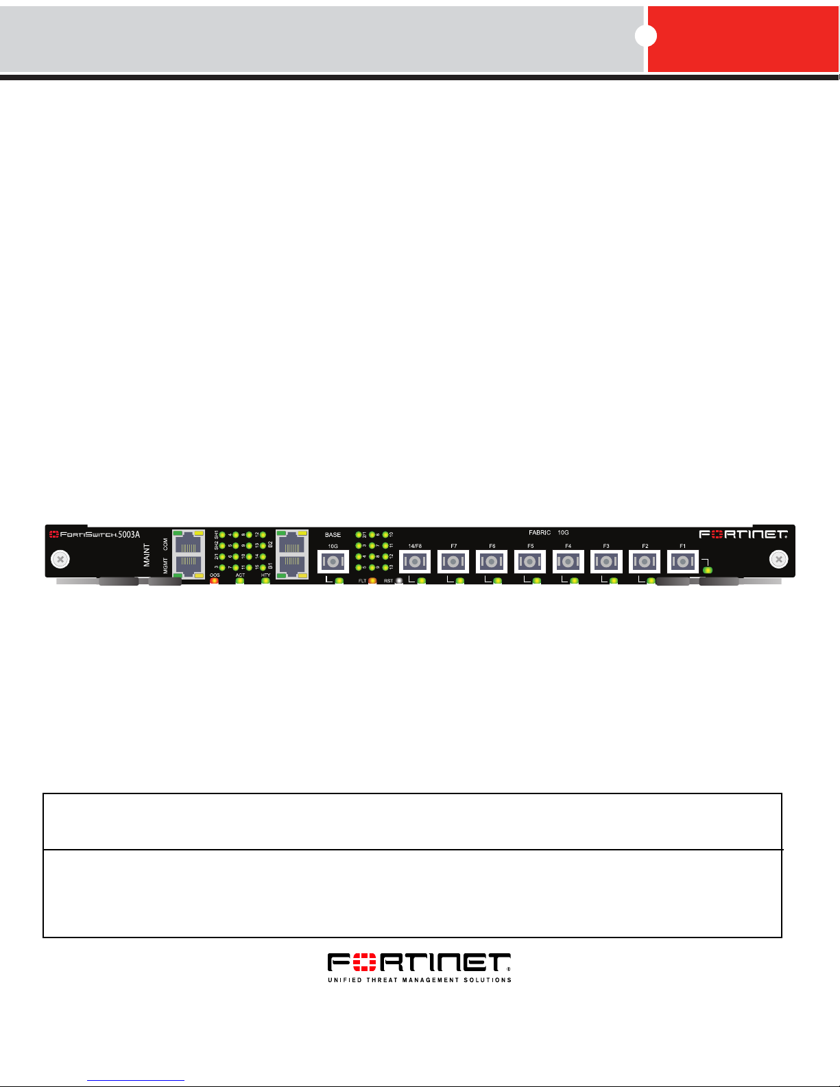
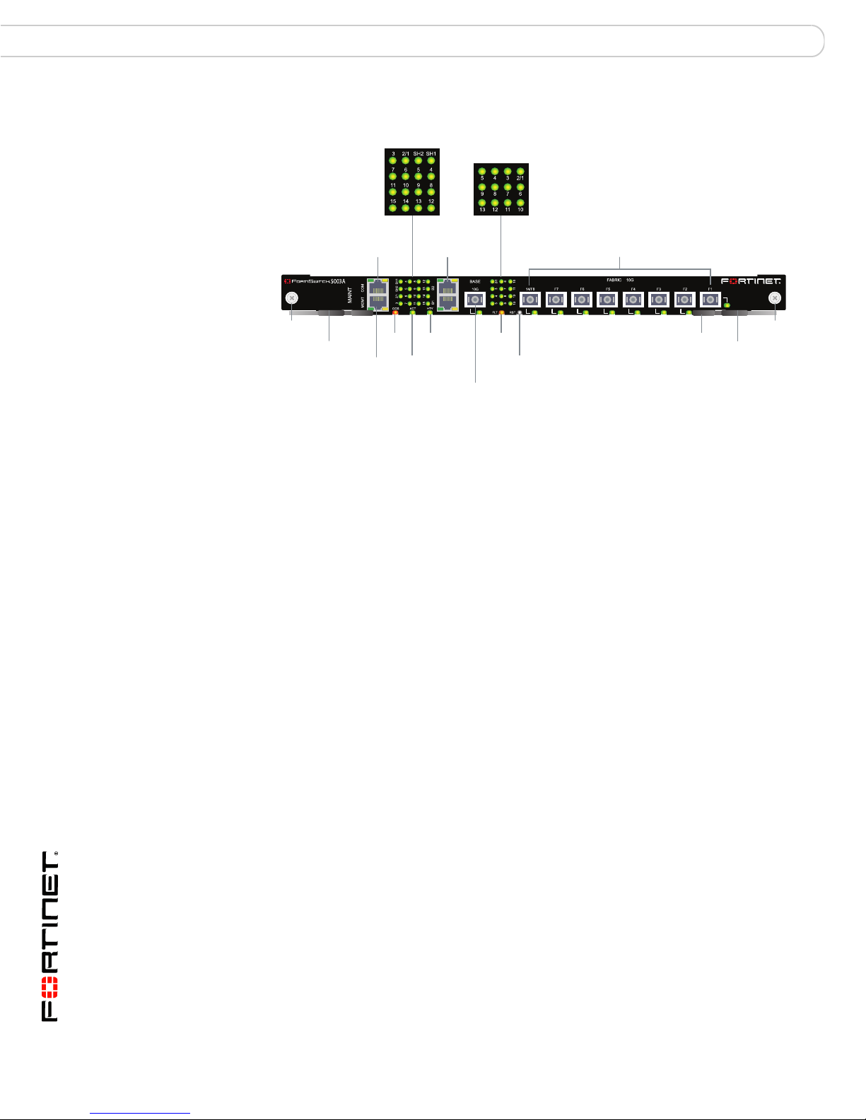
Figure 1: FortiSwitch-5003A front panel
Base Network
Activity LEDs
Fabric Network
Activity LEDs
B1 B2
Base 1G
Copper
Healthy
LED
Active
LED
BASE 10G Optical
or Copper SFP
Fault
LED
14/F8 F7 F6 F5 F4 F3 F2 F1
Fabric 10G Optical or Copper SFP
Reset
Switch
Hot Swap
LED
Retention
Screw
Extraction
Lever
Retention
Screw
Extraction
Lever
RJ-45 COM
Port
MGMT 1G
Copper
Interface
OOS
LED
• One front panel base backplane 10-gigabit optical or copper SFP+ interface
(BASE 10G) that connects to the base backplane channel
• Eight front panel fabric backplane 10-gigabit optical or copper SFP+ interfaces
(14/F8, F7, F6, F5, F4, F3, F2, and F1)
• One gigabit out of band management ethernet interface (MGMT)
• One RJ-45, RS-232 serial console connection (COM)
• Mounting hardware
• LED status indicators
• IEEE 802.1q VLANs
• IEEE 802.3ad layer-2 link aggregation
• Link aggregation using a hash algorithm based on source and destination IP
addresses
• Multi-Spanning Tree Protocol (MTSP) (IEEE 802.1s) to support redundant
FortiSwitch-5003A boards and external MTSP-compatible switches
• Heartbeat between FortiGate-5001A and FortiGate-5005FA2 boards and the
FortiSwitch-5003A over the fabric channel to support MTSP (configurable from
the FortiGate-5001A and FortiGate-5005FA2 systems)
• Standard FortiOS command line interface (CLI) for configuring fabric switch
settings (VLANs, MTSP, trunks, and so on)
Front panel LEDs and connectors
From the FortiSwitch-5003A font panel you can view the status of the board LEDs
to verify that the board is functioning normally. The front panel includes a reset
switch for restarting the FortiSwitch-5003A board.
The front panel also contains connectors to the fabric and base channels, an out
of band management ethernet interface, and an RJ-45 RS-232 console port for
connecting to the FortiSwitch-5003A CLI.
FortiSwitch-5003A System Guide
6 01-30000-77803-20080917
Page 7
FortiSwitch-5003A system Front panel LEDs and connectors
LEDs
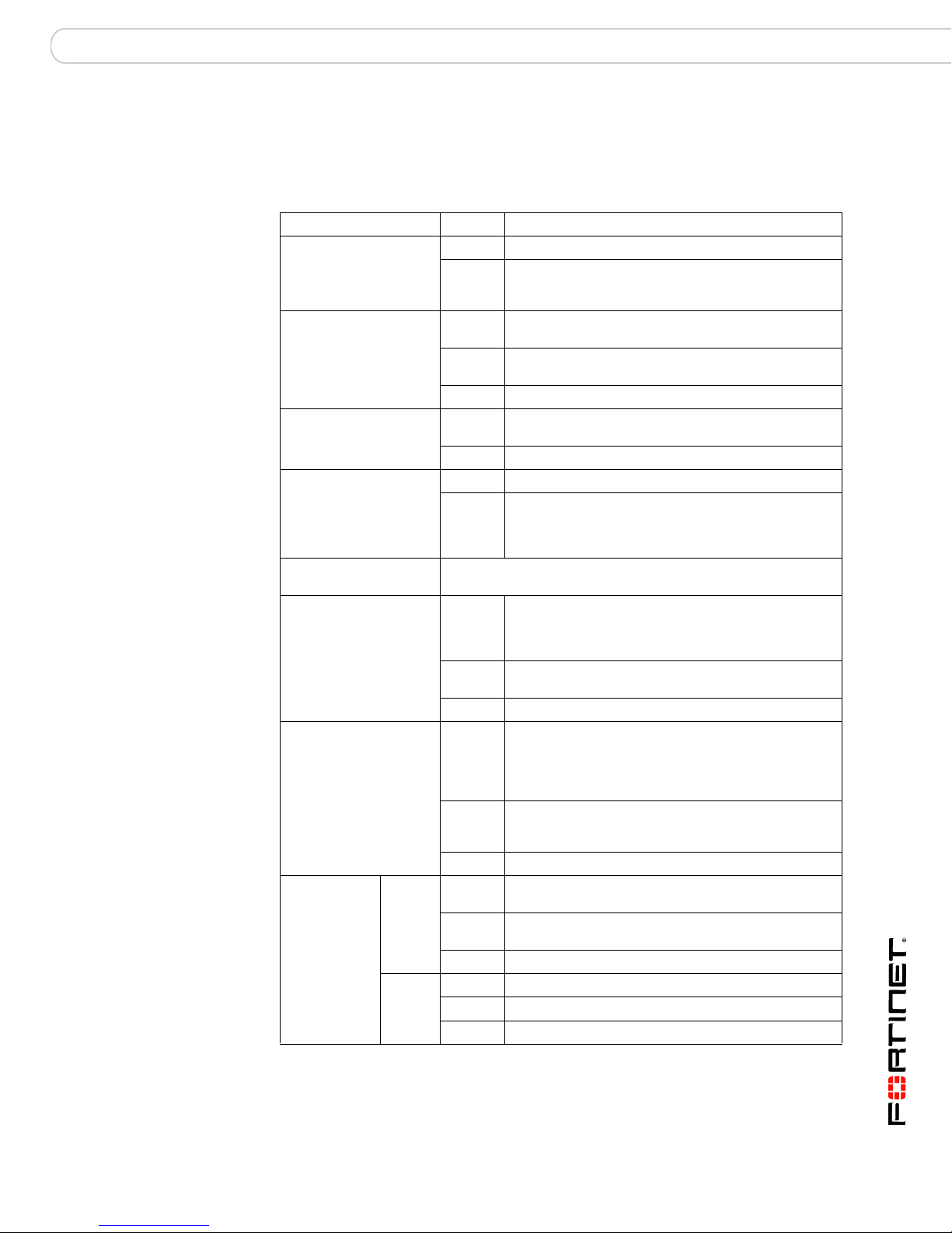
Ta bl e 1 lists and describes the FortiSwitch-5003A front panel LEDs.
Table 1: FortiSwitch-5003A front panel LEDs and switches
LED State Description
OOS (Out of Service) Off Normal operation.
Red Out of service. The LED turns on if the
ACT (Active) Green The FortiSwitch-5003A board is powered on and
Yellow Caution status. Caution status is indicated by the
Off The board is not connected to power.
HTY (Healthy) Green The FortiSwitch-5003A board is powered on and
Off The board health system has detected a fault.
FLT (Fault) Off Normal operation.
Yellow Cannot establish a link to a configured interface or
RST (Reset switch) Press and hold Reset for three seconds to restart the
Base Network Activity
LEDs
Fabric Network
Activity LEDs
MGMT, B1,
B2
(Management
and base
1-gigabit
LEDs)
Link/Act
(Left
LED)
Speed
(Right
LED)
FortiSwitch-5003A board.
Solid
Green
Blinking
Green
Off No link.
Solid
Green
Blinking
Green
Off No link.
Solid
Green
Blinking
Green
Off No Link
Green Connection at 1 Gbps.
Amber Connection at 100 Mbps.
Off Connection at 10 Mbps.
FortiSwitch-5003A board fails. The LED may also
flash briefly when the board is powering on.
operating normally.
fault condition of the HTY and FLT LEDs.
operating normally.
another connection problem external to the
FortiSwitch-5003A board. This LED may indicate
issues that do not affect normal operation.
Indicates this interface is connected to the 1-gigabit
base channel interface of a FortiGate-5000 board.
Table 2 on page 8 lists the base network activity
LEDs and the interface that each represents.
Indicates 1-gigabit network traffic on this interface.
Indicates this interface is connected to the
10/1-gigabit fabric channel interface of a
FortiGate-5000 board. Table 4 on page 10 lists the
fabric network activity LEDs and the interface that
each represents.
Indicates 10/1-gigabit network traffic on this interface.
Table 4 on page 10 lists the fabric network activity
LEDs and the interface that each represents.
Indicates this interface is connected with the correct
cable and the attached network device has power.
Indicates network traffic on this interface.
FortiSwitch-5003A System Guide
01-30000-77803-20080917 7
Page 8
Front panel LEDs and connectors FortiSwitch-5003A system
Table 1: FortiSwitch-5003A front panel LEDs and switches (Continued)
LED State Description
Solid
BASE 10G, 14/F8, F7,
F6, F5, F4, F3, F2, F1
(Base and Fabric 10
gigabit LEDs)
HS (Hot Swap) Blue The FortiSwitch-5003A is ready to be hot-swapped
Green
Blinking
Green
Off No link.
Flashing
Blue
Off Normal operation. The FortiSwitch-5003A board is in
Indicates this interface is connected to a 10-gigabit
network device with the correct cable and the
attached network device has power.
Indicates 10-gigabit network traffic on this interface.
(removed from the chassis). If the HS light is blue
and no other LEDs are lit the FortiSwitch-5003A
board has lost power.
The FortiSwitch-5003A is changing from hot swap to
running mode or from running mode to hot swap.
This happens when the FortiSwitch-5003A board is
starting up or shutting down.
contact with the chassis backplane.
Base channel interfaces
Tab le 2 lists and describes the FortiSwitch-5003A base backplane channel
interfaces. The base backplane interfaces are not configurable or visible from the
FortiSwitch-5003A CLI.
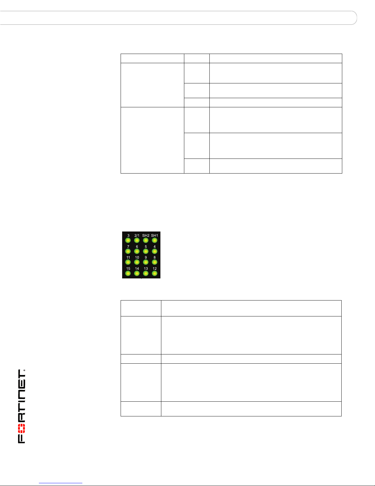
Figure 2: FortiSwitch-5003A base network activity LEDs
Table 2: Base channel interfaces and network activity LEDs
Interface
Name
SH1 If the FortiSwitch-5003A board is in the first hub/switch fabric slot, this
15 and SH2 Not used.
2/1 Base channel connection between base channels 1 and 2.
3 to 14 Base channel connection to FortiGate-5000 boards in chassis slots 3 to
Description
LED indicates a backplane connection to shelf manager 1. If the
FortiSwitch-5003A board is in second hub/switch fabric slot this LED
indicates a backplane connection to shelf manager 2.
This LED may not be lit even if a shelf manager is present if the shelf
manager is configured to use its front panel interface.
The 2/1 LED is lit if there is any board capable of connecting to the base
channel in the other slot. For example, if the FortiSwitch-5003A board is
installed in the first hub/switch fabric slot, this LED will be lit if any board
is installed in the second hub/switch fabric slot, including a
FortiSwitch-5003A board or any FortiGate-5000 board.
14.
FortiSwitch-5003A System Guide
8 01-30000-77803-20080917
Page 9

FortiSwitch-5003A system Front panel LEDs and connectors
Table 2: Base channel interfaces and network activity LEDs
Interface
Name
B1 and B2 Front panel gigabit base channel interfaces B1 and B2.
BASE 10G Front panel 10-gigabit base channel interface.
Fabric channel interfaces
Ta bl e 3 lists and describes the FortiSwitch-5003A fabric channel interfaces. You
can configure fabric interface settings, group fabric interfaces into trunks, and
configure MSTP spanning tree settings for fabric interfaces from the
FortiSwitch-5003A CLI.
Table 3: Fabric channel interfaces
Interface Name
Front Panel CLI*
2/1 slot-2/1 Interface between fabric channel 1 and fabric channel 2.
3 to 13 slot-3 to
14/F8 slot-14/f8 Front panel interface 14/F8.
F1 to F7 f1 to f7 Front panel 10-gigabit fabric interfaces F1 to F7.
* You can configure settings for FortiSwitch-5003A fabric interfaces from the
FortiSwitch-5003A CLI. The CLI columns show the names of the interfaces as they appear
on the FortiSwitch-5003A CLI.
Description
Use these interfaces to connect your network to the base channel, to
connect base channel 1 to base channel 2, or to connect a base channel
on one chassis to a base channel on another chassis.
Use this interface to connect a 10-gigabit network to the base channel.
10-gigabit communication is not supported across the base channels but
this interface is still available if you need to connect the base channel to
a 10-gigabit network.
Description
If there are two FortiSwitch-5003A boards installed in a
chassis this interface can be used to communicate between
them. In some configurations you may have to disable this
communication. See the FortiGate-5000 Backplane
Communication Guide for more information.
Fabric backplane slots 3 to 13.
slot-13
The 3 to 13 fabric network activity LEDs are lit if there are
FortiGate boards in chassis slots 3 to 13.
Fabric backplane slot 14 and front panel interface 14/F8
share the same FortiSwitch-5003A switch port. By default the
the front panel interface 14/F8 is enabled and fabric
backplane slot 14 is disabled. You can change this setting
using a switch on the FortiSwitch-5003A board. See “Setting
the FortiSwitch-5003A configuration switch” on page 13.
Use these interfaces to connect your network to the fabric
channel, to connect fabric channel 1 to fabric channel 2, or to
connect a fabric channel on one chassis to a fabric channel
on another chassis.
The fabric network activity LEDs show links and network activity for the interfaces
and connections listed in Tab le 4 .
Figure 3: FortiSwitch-5003A fabric network activity LEDs
FortiSwitch-5003A System Guide
01-30000-77803-20080917 9
Page 10

FortiSwitch-5003A configurations FortiSwitch-5003A system
Table 4: Fabric network activity LEDs
Fabric network
activity LED
2/1 Fabric channel connection between fabric channel 1 and fabric
3 to 13 Fabric backplane connection to FortiGate-5000 boards in chassis slots
Front panel connectors
Tab le 5 lists and describes the FortiSwitch-5003A front panel connectors.
Table 5: FortiSwitch-5003A connectors
Connector Type Speed Protocol Description
MGMT RJ-45 10/100/1000
COM RJ-45 9600 bps
B1, B2 RJ-45 10/100/1000
BASE 10G SFP+ 10 Gbps Ethernet SFP+ 10 gigabit connection to the base
FABRIC
10G, 14/F8,
F7, F6, F5,
F4, F3, F2,
F1
Interface or connection
channel 2. This LED is lit if there are two FortiSwitch-5003A boards
installed in the chassis to indicate fabric backplane communication
between them.
3 to 13.
Base-T
8/N/1
Base-T
SFP+ 10 Gbps Ethernet SFP+ 10 gigabit connection to the fabric
Ethernet Copper gigabit connection to out of band
RS-232
serial
Ethernet Copper gigabit connection to the base
management interface.
Serial connection to the command line
interface.
backplane channel.
backplane channel.
backplane channel.
FortiSwitch-5003A configurations
You can operate the FortiSwitch-5003A board as a fabric and base channel
layer-2 switch for any FortiGate-5000 board. The FortiSwitch-5003A board is
compatible with all FortiGate-5000 boards.
See the FortiGate-5000 Backplane Communication Guide for information about
FortiSwitch-5003A fabric and base channel switching. This document also
contains a FortiSwitch-5003A CLI reference.
Base and fabric gigabit switching within a chassis
Figure 4 shows a FortiGate-5050 chassis with a FortiSwitch-5003A board in slot 1
and two FortiGate-5001A boards in slots 3 and 4. In this configuration the
FortiGate-5001A boards are using base channel 1 for HA heartbeat
communication. The FortiGate-5001A boards use base1 as the HA heartbeat
interface.
FortiSwitch-5003A System Guide
10 01-30000-77803-20080917
Page 11

FortiSwitch-5003A system FortiSwitch-5003A configurations
1
2
2
3
4
5
SMC
1
SMC
POWER
Base channel 1
HA Heartbeat
Communication
Fabric Channel 2
10-gigabit Data
Communication
FortiGate-RTM-XB2
Module installed in RTM
slot 3 provides two
10-gigabit fabric channels
and NP2 acceleration for
the FortiGate-5001A board
FortiGate-5001A Board
Installed in FortiGate-5050
front panel slot 3
Fabric Channel 1
10 Gigabit Data
Communication
Internal 10-gigabit
Network Connected
to Fabric Channel 2
External 10-gigabit
Network Connected
to Fabric Channel 1
External
Network
Internal Network
Figure 4: FortiSwitch-5003A base channel 1 HA heartbeat communication
5000SM
10/100
ETH0
Service
link/Act
ETH1
STATUS
10/100
ETH0
link/Act
Hot Swap
RESET
5050SAP
SERIAL
1
ALARM
Base and fabric 10-gigabit switching within a chassis
One FortiGate-RTM-XB2 provides 10-gigabit connections to both
FortiGate-5001A fabric channels. The FortiGate-RTM-XB2 also provides NP2
packet acceleration for each fabric channel. To effectively use NP2 acceleration,
packets must be received by the FortiGate-5001A board on one fabric channel
and exit from the FortiGate-5001A board on the same fabric channel or on the
other fabric channel. See the FortiGate-RTM-XB2 System Guide for more
information.
Figure 5 shows a FortiGate-5050 chassis containing two FortiSwitch-5003A
boards and one FortiGate-5001A board. Using these components this chassis
supplies 10-gigabit connectivity between the external and internal network.
Figure 5: Example 10-gigabit connection between internal and external networks
5000SM
10/100
ETH0
Service
link/Act
ETH1
SERIAL
2
STATUS
10/100
ETH0
link/Act
Hot Swap
RESET
FortiSwitch-5003A System Guide
01-30000-77803-20080917 11
5
4
3
2
1
5000SM
10/100
SMC
ETH0
Service
link/Act
ETH1
STATUS
10/100
RESET
ETH0
link/Act
2
5050SAP
SERIAL
Hot Swap
1
POWER
5000SM
10/100
link/Act
ETH1
SERIAL
10/100
2
ETH0
ALARM
link/Act
SMC
ETH0
Service
STATUS
Hot Swap
RESET
1
Page 12

FortiSwitch-5003A configurations FortiSwitch-5003A system
Layer-2 link aggregation and redundancy configurations
The FortiSwitch-5003A board supports 802.3ad layer-2 link aggregation, 802.1q
VLANs, and 802.1s Multi-Spanning Tree Protocol (MTSP) for the fabric channels.
You can use these features to configure link aggregation and support redundant
FortiSwitch-5003A switch configurations to distribute traffic to multiple
FortiGate-5000 boards.
See the FortiGate-5000 Backplane Communication Guide for more information
about FortiSwitch-5003A link aggregation and redundancy.
Figure 6 shows a basic link aggregation configuration using a single
FortiSwitch-5003A board. In this configuration the external switch is connected to
FortiSwitch-5003A front panel f5 interface. The switch adds VLAN tags to traffic
from the internal and external networks.
Figure 6: Basic link aggregation configuration
Internal Network
External
Network
Internal and External
10 Gigabit Networks
Connected to
FortiSwitch-5003A
Front Panel Interface F5
and to Fabric Channel 2
External Switch
VLAN
Tagged
Traffic
Three FortiGate-RTM-XB2
modules installed in RTM
5
slots 3, 4, and 5 to
provide 10-gigabit
4
fabric interfaces and
NP2 acceleration for each
3
2
POWER
1
5000SM
10/100
SMC
ETH0
Service
link/Act
ETH1
STATUS
10/100
RESET
ETH0
link/Act
2
5050SAP
SERIAL
Hot Swap
1
ALARM
5000SM
10/100
ETH0
Service
link/Act
ETH1
SERIAL
10/100
2
ETH0
link/Act
SMC
STATUS
Hot Swap
RESET
1
FortiGate-5001A board.
Distributed 10-gigabit
Data Communication
on Fabric Channel 2
FortiSwitch-5003A System Guide
12 01-30000-77803-20080917
Page 13

Hardware installation Setting the FortiSwitch-5003A configuration switch
Hardware installation
Before use, the FortiSwitch-5003A module must be correctly inserted into the first
or second hub/switch fabric slot of an Advanced Telecommunications Computing
Architecture (ACTA) chassis such as the FortiGate-5140 or FortiGate-5050.
Before inserting the board into a chassis you should make sure the configuration
switch is set correctly.
This chapter describes:
• Setting the FortiSwitch-5003A configuration switch
• FortiSwitch-5003A mounting components
• Inserting a FortiSwitch-5003A board
• Removing a FortiSwitch-5003A board
• Resetting a FortiSwitch-5003A board
• Troubleshooting
Setting the FortiSwitch-5003A configuration switch
The SW3 switch on the FortiSwitch-5003A board is factory set by Fortinet with the
front panel 14/F8 interface enabled and the fabric backplane slot 14 disabled. This
means you can connect the FortiSwitch-5003A front panel 14/F8 interface to a
network but you cannot connect a FortiGate-5000 board in slot 14 to the fabric
backplane.
The SW3 switch on the FortiSwitch-5003A board can be used to switch between
enabling 14/F8 front panel interface and enabling the fabric backplane slot 14
interface.
Figure 7: SW3 factory default setting (front panel interface 14/F8 enabled)
Default (Front panel 14/F8 interface enabled)
ON
SW3
1 2 3 4
Figure 8: SW3 changed (backplane slot 14 enabled)
Backplane slot 14 enabled
ON
SW3
1 2 3 4
1 ON
2 OFF
3 ON
4 ON
1 OFF
2 OFF
3 ON
4 ON
FortiSwitch-5003A System Guide
01-30000-77803-20080917 13
Page 14

Setting the FortiSwitch-5003A configuration switch Hardware installation
!
FortiGate-5003A
Front Faceplate
Location of SW3
SW1
ON
1 2 3 4
FortiGate-5003A
board (top view)
1 2 3 4
ON
SW3
To change or verify the SW3 switch settings
To complete this procedure, you need:
• A FortiSwitch-5003A board
• A tool for changing the SW3 switch setting (optional)
• An electrostatic discharge (ESD) preventive wrist strap with connection cord
Caution: FortiSwitch-5003A boards must be protected from static discharge and physical
shock. Only handle or work with FortiSwitch-5003A boards at a static-free workstation.
Always wear a grounded electrostatic discharge (ESD) preventive wrist strap when
handling FortiSwitch-5003A boards.
1 Attach the ESD wrist strap to your wrist and to an ESD socket or to a bare metal
surface on a chassis or frame.
2 If you have installed the FortiSwitch-5003A board in a chassis, remove it.
For removal instructions, see “Removing a FortiSwitch-5003A board” on page 18.
3 Use Figure 9 to locate SW3 on the FortiSwitch-5003A board.
Figure 9: Location of SW3 on the FortiSwitch-5003A board
4 If required, change SW3 to the required setting (see Figure 7 and Figure 8).
5 Insert the FortiSwitch-5003A board into a chassis and verify that the board starts
up and operates correctly.
For inserting instructions, see “Inserting a FortiSwitch-5003A board” on page 16.
FortiSwitch-5003A System Guide
14 01-30000-77803-20080917
Page 15

Hardware installation FortiSwitch-5003A mounting components
FortiSwitch-5003A mounting components
To install a FortiSwitch-5003A board you slide the board into a hub/switch fabric
slot in the front of an ATCA chassis and then use the mounting components to
lock the board into place in the slot. When locked into place and positioned
correctly the board front panel is flush with the chassis front panel. The board is
also connected to the chassis backplane.
Note: FortiSwitch-5003A boards are horizontal when inserted into a FortiGate-5050
chassis and vertical when inserted into a FortiGate-5140 chassis. The inserting and
removing procedures are the same in either case. For clarity the descriptions in this
document refer to the left (top) and right (bottom) mounting components
To position the board correctly you must use the mounting components shown in
Figure 10 for the right (bottom) of the FortiSwitch-5003A front panel. The
mounting components on the left (top) of the front panel are the same but
reversed. The FortiSwitch-5003A mounting components align the board in the
chassis slot and are used to insert and eject the board from the slot.
Figure 10: FortiSwitch-5003A right (bottom) mounting components
Closed
Alignment Pin
Retention
Screw
Handle
Lock
Handle
Alignment
Pin
Retention
Screw
Lock
Open
Alignment Pin
Alignment
Pin
Retention
Hook
(right handle
only)
Lock
Retention
Handle
Handle
Screw
Hook
(right handle
only)
Screw
Lock
The FortiSwitch-5003A handles align the board in the chassis slot and are used to
insert and eject the board from the slot. The right (bottom) handle activates a
microswitch that turns on or turns off power to the board. When the right (bottom)
handle is open the microswitch is off and the board cannot receive power. When
the right (bottom) handle is fully closed the microswitch is on and if the board is
fully inserted into a chassis slot the board can receive power.
Note: You can use front panel reset switch to cycle the power and reset the board without
removing the board from the chassis. See “Resetting a FortiSwitch-5003A board” on
page 20.
FortiSwitch-5003A System Guide
01-30000-77803-20080917 15
Page 16

Inserting a FortiSwitch-5003A board Hardware installation
!
!
Unlock
Handle
Inserting a FortiSwitch-5003A board
The FortiSwitch-5003A board must be fully installed in a chassis slot, with the
handles closed and locked and retention screws fully tightened for the
FortiSwitch-5003A board to receive power and operate normally. If the
FortiSwitch-5003A board is not receiving power, the HS LED glows solid blue and
all other LEDs remain off. See “Front panel LEDs and connectors” on page 6.
It is important to carefully seat the FortiSwitch-5003A board all the way into the
chassis, to not use too much force on the handles, and to make sure that the
handles are properly locked. Only then will the FortiSwitch-5003A board power-on
and start up correctly.
FortiSwitch-5003A boards are hot swappable. The procedure for inserting
a FortiSwitch-5003A board into a chassis slot is the same whether or not the
chassis is powered on.
To insert a FortiSwitch-5003A board into a chassis slot
Caution: Do not carry the FortiSwitch-5003A board by holding the handles or retention
screws. When inserting or removing the FortiSwitch-5003A board from a chassis slot,
handle the board by the front panel. The handles are not designed for carrying the board. If
the handles become bent or damaged the FortiSwitch-5003A board may not align correctly
in the chassis slot.
To complete this procedure, you need:
• A FortiSwitch-5003A board
• An ATCA chassis with an empty hub/switch fabric slot
• An electrostatic discharge (ESD) preventive wrist strap with connection cord
Caution: FortiSwitch-5003A boards must be protected from static discharge and physical
shock. Only handle or work with FortiSwitch-5003A boards at a static-free workstation.
Always wear a grounded electrostatic discharge (ESD) preventive wrist strap when
handling FortiSwitch-5003A boards.
1 Attach the ESD wrist strap to your wrist and to an ESD socket or to a bare metal
surface on the chassis or frame.
2 If required, remove the protective metal frame that the FortiSwitch-5003A board
has been shipped in.
3 Insert the FortiSwitch-5003A board into the empty slot in the chassis.
4 Unlock the handles by squeezing the handle locks.
5 Open the left (top) and right (bottom) handles to their fully open positions.
FortiSwitch-5003A System Guide
16 01-30000-77803-20080917
Page 17

Hardware installation Inserting a FortiSwitch-5003A board
!
Caution: To avoid damaging the lock, make sure you squeeze the handles fully to unlock
them before opening. The handles should pop easily out of the board front panel.
Alignment Pin
Alignment Pin
Handle
Open
Handle
Lock
6 Insert the FortiSwitch-5003A board into the empty slot in the chassis.
7 Carefully guide the board into the chassis using the rails in the slot.
Insert the board by applying moderate force to the front faceplate (not the
handles) to slide the board into the slot. The board should glide smoothly into the
chassis slot. If you encounter any resistance while sliding the board in, the board
could be aligned incorrectly. Pull the board back out and try inserting it again.
8 Slide the board in until the alignment pins are inserted half way into their sockets
in the chassis.
9 Turn both handles to their fully-closed positions.
The handles should hook into the sides of the chassis slot. Closing the handles
draws the FortiSwitch-5003A board into place in the chassis slot and into full
contact with the chassis backplane. The FortiSwitch-5003A front panel should be
in contact with the chassis front panel. When the handles are fully-closed they
lock into place.
As the right (bottom) handle closes the microswitch is turned on, supplying power
to the board. If the chassis is powered on the HS LED starts flashing blue. If the
board is aligned correctly, inserted all the way into the slot, and the right (bottom)
handle is properly closed the HS LED flashes blue for a few seconds. At the same
time the ACT and HTY LEDs turn green. After a few seconds the HS LED goes
out and the FortiSwitch-5003A firmware starts up. If the board is operating
correctly, the front panel LEDs are lit as described in Tab le 6 .
Table 6: FortiSwitch-5003A normal operating LEDs
LED State
OOS (Out of
Service)
ACT (Active) Green
HTY (Healthy) Green
FLT (Fault) Off
Off
If the board has not been inserted properly the HS LED changes to solid blue and
all other LEDS turn off. If this occurs, open the handles, slide the board part way
out, and repeat the insertion process.
FortiSwitch-5003A System Guide
01-30000-77803-20080917 17
Page 18

Removing a FortiSwitch-5003A board Hardware installation
Tighten
Retention
Screw
!
!
10 Once the board is inserted correctly, fully tighten the retention screws to lock the
FortiSwitch-5003A board into position in the chassis slot.
Removing a FortiSwitch-5003A board
The following procedure describes how to correctly use the FortiSwitch-5003A
mounting components described in “FortiSwitch-5003A mounting components” on
page 15 to remove a FortiSwitch-5003A board from an ATCA chassis slot.
FortiSwitch-5003A boards are hot swappable. The procedure for removing
a FortiSwitch-5003A board from a chassis slot is the same whether or not the
chassis is powered on.
To remove a FortiSwitch-5003A board from a chassis slot
Caution: Do not carry the FortiSwitch-5003A board by holding the handles or retention
screws. When inserting or removing the FortiSwitch-5003A board from a chassis slot,
handle the board by the front panel. The handles are not designed for carrying the board. If
the handles become bent or damaged the FortiSwitch-5003A board may not align correctly
in the chassis slot.
To complete this procedure, you need:
• An ATCA chassis with a FortiSwitch-5003A board installed
• An electrostatic discharge (ESD) preventive wrist strap with connection cord
Caution: FortiSwitch-5003A boards must be protected from static discharge and physical
shock. Only handle or work with FortiSwitch-5003A boards at a static-free workstation.
Always wear a grounded electrostatic discharge (ESD) preventive wrist strap when
handling FortiSwitch-5003A boards.
1 Attach the ESD wrist strap to your wrist and to an ESD socket or to a bare metal
surface on the chassis or frame.
2 Disconnect all cables from the FortiSwitch-5003A board, including all network
cables and the console cable.
FortiSwitch-5003A System Guide
18 01-30000-77803-20080917
Page 19

Hardware installation Removing a FortiSwitch-5003A board
!
Handle
Alignment Pin
Open
Alignment Pin
Lock
Handle
Fully Closed
and Locked
Alignment Pin
Handle
Close
Alignment Pin
Handle
3 Fully loosen the FortiSwitch-5003A retention screws.
Retention
Screw
Loosen
4 Unlock the handles by squeezing the handle locks.
5 Open the handles to their fully open positions.
Caution: To avoid damaging the lock, make sure you squeeze the handles fully to unlock
them before opening. The handles should pop easily out of the board front panel.
Opening the handles turns off the microswitch, turns off all LEDs, and ejects the
board from the chassis slot. You need to use moderate pressure on the handles to
eject the board.
6 Pull the board about half way out.
7 Turn both handles to their fully-closed positions.
When the handles are fully-closed they lock into place.
8 Carefully slide the board completely out of the slot.
9 Re-attach the protective metal frame if you are going ship the FortiSwitch-5003A
board or store it outside of a chassis.
FortiSwitch-5003A System Guide
01-30000-77803-20080917 19
Page 20

Resetting a FortiSwitch-5003A board Hardware installation
Resetting a FortiSwitch-5003A board
You can use the front panel reset switch to cycle the power and reset the
FortiSwitch-5003A board without ejecting the board from its slot. Press and hold
the reset switch for three seconds to restart the board. For the location of the reset
switch, see “The FortiSwitch-5003A board includes the following features:” on
page 5.
Troubleshooting
This section describes the following troubleshooting topics:
• FortiSwitch-5003A does not startup
FortiSwitch-5003A does not startup
Positioning of FortiSwitch-5003A handles and a few other causes may prevent a
FortiSwitch-5003A board for starting up correctly.
All chassis: handles not fully closed
If the handles are damaged or positioned incorrectly the FortiSwitch-5003A board
will not start up. Make sure the handles are correctly aligned, fully inserted and
locked.
All chassis: Firmware problem
If the FortiSwitch-5003A board is receiving power and the handles are fully closed,
and you have restarted the chassis and the FortiSwitch-5003A still does not start
up, the problem could be with FortiOS. Connect to the FortiSwitch-5003A console
and try cycling the power to the board. If the BIOS starts up, interrupt the BIOS
startup and install a new firmware image. For details about installing a new
firmware image in this way, see the FortiGate-5000 Series Firmware and FortiUSB
Guide.
If this does not solve the problem, contact Fortinet Technical Support.
FortiSwitch-5003A System Guide
20 01-30000-77803-20080917
Page 21

Quick Configuration Guide Registering your Fortinet product
Quick Configuration Guide
This section is a quick start guide to connecting and configuring a
FortiSwitch-5003A board.
Before using this chapter, your FortiGate-5000 series or compatible ATCA chassis
should be mounted and connected to your power system. In addition, your
FortiSwitch-5003A board should be inserted into the chassis. The
FortiSwitch-5003A board should also be powered up and the front panel LEDs
should indicate that the boards are functioning normally.
This chapter includes the following topics:
• Registering your Fortinet product
• Factory default settings
• Basic configuration
• Upgrading FortiSwitch-5003A firmware
• Additional configuration
Registering your Fortinet product
Register your Fortinet product to receive Fortinet customer services such as
product updates and technical support. You must also register your product for
FortiGuard services such as FortiGuard Antivirus and Intrusion Prevention
updates and for FortiGuard Web Filtering and AntiSpam.
Register your product by visiting http://support.fortinet.com and selecting Product
Registration.
To register, enter your contact information and the serial numbers of the Fortinet
products that you or your organization have purchased. You can register multiple
Fortinet products in a single session without re-entering your contact information.
Factory default settings
The FortiSwitch-5003A unit ships with a factory default configuration. The default
configuration allows you to connect to and use the FortiSwitch-5003A CLI to
configure the FortiSwitch-5003A board. To configure the FortiSwitch-5003A board
you add an administrator password, change the management interface IP
address, and, if required, configure the default route for the management
interface.
Table 7: FortiSwitch-5003A factory default settings
Administrator Account User Name: admin
MGMT IP/Netmask 192.168.1.99/24
Default route Gateway: 192.168.1.254
FortiSwitch-5003A System Guide
01-30000-77803-20080917 21
Password: (none)
Device: mgmt
Page 22

Basic configuration Quick Configuration Guide
Note: At any time during the configuration process, if you run into problems, you can reset
the FortiSwitch-5003A board to the factory defaults and start over. From the CLI enter
execute factory-reset.
Basic configuration
1 Use the serial cable supplied with your FortiSwitch-5003A board to connect the
front panel RJ-45 COM port to the management computer serial port.
You can also connect to the CLI using an SSH or Telnet connection to the MGMT
interface. The default IP address is 192.168.1.99/24.
2 Start a terminal emulation program (HyperTerminal) on the management
computer. Use these settings:
Baud Rate (bps) 9600
Data bits 8
Parity None
Stop bits 1
Flow Control None
3 At the Login: prompt, type admin and press Enter twice (no password required).
4 Change the administrator password.
config admin user
edit admin
set password <password>
next
end
5 Configure the mgmt interface.
config system interface
edit mgmt
set ip <ip_address>/<netmask>
next
end
If you have connected to the FortiSwitch-5003A CLI using telnet or SSH, since
this step changes the mgmt interface IP address you will have to re-establish the
Telnet or SSH session.
6 Configure the default gateway for the management interface.
config route static
edit 1
set gateway <gateway_ip>
next
end
7 If your are installing two FortiSwitch-5003A boards in the same chassis, you may
need to enter the following command to disable communication between them.
config switch fabric-channel physical-port
edit slot-2/1
set status down
end
FortiSwitch-5003A System Guide
22 01-30000-77803-20080917
Page 23

Quick Configuration Guide Upgrading FortiSwitch-5003A firmware
end
See the FortiGate-5000 Backplane Communication Guide for more information.
Upgrading FortiSwitch-5003A firmware
Fortinet periodically updates the FortiSwitch-5003A FortiOS firmware to include
enhancements and address issues. After you have registered your
FortiSwitch-5003A security system (see “Registering your Fortinet product” on
page 21) you can download FortiSwitch-5003A firmware from the support web
site http://support.fortinet.com.
To upgrade the firmware
To use the following procedure, you must have a TFTP server the
FortiSwitch-5003A board can connect to.
1 Make sure the TFTP server is running.
2 Copy the new firmware image file to the root directory of the TFTP server.
3 Log into the FortiSwitch-5003A CLI.
4 Make sure the FortiGate board can connect to the TFTP server.
You can use the following command to ping the computer running the TFTP
server. For example, if the IP address of the TFTP server is 192.168.1.168:
execute ping 192.168.1.168
5 Enter the following command to copy the firmware image from the TFTP server to
the FortiSwitch-5003A board:
execute restore image tftp <name_str> <tftp_ipv4>
Where <name_str> is the name of the firmware image file and <tftp_ipv4> is
the IP address of the TFTP server. For example, if the firmware image file name is
image.out and the IP address of the TFTP server is 192.168.1.168, enter:
execute restore image tftp image.out 192.168.1.168
The FortiSwitch-5003A board responds with the message:
This operation will replace the current firmware version
Do you want to continue? (y/n)
6 Type y.
The FortiSwitch-5003A board uploads the firmware image file, upgrades to the
new firmware version, and restarts. This process takes a few minutes.
7 Reconnect to the CLI.
8 To confirm the firmware image is successfully installed, enter:
get system status
Additional configuration
You can use the FortiSwitch-5003A CLI to configure other basic system settings
such as using config system global to set system time settings and change
the system host name. Execute commands are also available for setting the
system time and date and backing up the configuration.
FortiSwitch-5003A System Guide
01-30000-77803-20080917 23
Page 24

Additional configuration Quick Configuration Guide
If you are using the FortiSwitch-5003A system for link aggregation or just to pass
VLANs you need to use the config switch fabric-channel command. This
command has 4 keywords:
• interface to add VLANs to interfaces and other settings
• physical-port to enable listening for heartbeats from FortiGate-5000 units
on the fabric channel and to configure interfaces to be up or down
• stp to configure MTSP
• trunk to aggregate FortiSwitch-5003A fabric interfaces
See “Layer-2 link aggregation and redundancy configurations” on page 12 for
some examples of using these commands. See also the FortiGate-5000
Backplane Guide for a complete FortiSwitch-5003A CLI reference as well as
example FortiSwitch-5003A configurations.
FortiSwitch-5003A System Guide
24 01-30000-77803-20080917
Page 25

For more information Fortinet documentation
For more information
Support for your Fortinet product is available as online help from within the
web-based manager, from the Tools and Documentation CD included with the
product, on the Fortinet Technical Documentation web site, from the Fortinet
Knowledge Center web site, as well as from Fortinet Technical Support.
Fortinet documentation
The most up-to-date publications and previous releases of Fortinet product
documentation are available from the Fortinet Technical Documentation web site
at http://docs.forticare.com. FortiGate-5000 series documentation is located in its
own section of the site at http://docs.forticare.com/fgt5k.html.
Fortinet Tools and Documentation CD
Fortinet documentation is available from the Fortinet Tools and Documentation
CD shipped with your Fortinet product. The documents on this CD are current for
your product at shipping time. For the latest versions of all Fortinet documentation
see the Fortinet Technical Documentation web site at http://docs.forticare.com.
Fortinet Knowledge Center
Additional information about Fortinet products is available from the Fortinet
Knowledge Center. The knowledge center contains troubleshooting and how-to
articles, FAQs, technical notes, and more. Visit the Fortinet Knowledge Center at
http://kc.forticare.com.
Comments on Fortinet technical documentation
Please send information about any errors or omissions in this document, or any
Fortinet technical documentation, to techdoc@fortinet.com.
Customer service and technical support
Fortinet Technical Support provides services designed to make sure that your
Fortinet systems install quickly, configure easily, and operate reliably in your
network.
Please visit the Fortinet Technical Support web site at http://support.fortinet.com
to learn about the technical support services that Fortinet provides.
Register your Fortinet product
Register your Fortinet product to receive Fortinet customer services such as
product updates and technical support. You must also register your product for
FortiGuard services such as FortiGuard Antivirus and Intrusion Prevention
updates and for FortiGuard Web Filtering and AntiSpam.
Register your product by visiting http://support.fortinet.com and selecting Product
Registration.
To register, enter your contact information and the serial numbers of the Fortinet
products that you or your organization have purchased. You can register multiple
Fortinet products in a single session without re-entering your contact information.
FortiSwitch-5003A System Guide
01-30000-77803-20080917 25
Page 26

© Copyright 2008 Fortinet, Inc. All rights reserved. No part of this publication
including text, examples, diagrams or illustrations may be reproduced,
transmitted, or translated in any form or by any means, electronic, mechanical,
manual, optical or otherwise, for any purpose, without prior written permission of
Fortinet, Inc.
Trademarks
Fortinet, FortiGate and FortiGuard are registered trademarks and Dynamic Threat
Prevention System (DTPS), APSecure, FortiASIC, FortiBIOS, FortiBridge,
FortiClient, FortiGate, FortiGate Unified Threat Management System, FortiGuardAntispam, FortiGuard-Antivirus, FortiGuard-Intrusion, FortiGuard-Web, FortiLog,
FortiAnalyzer, FortiManager, FortiOS, FortiPartner, FortiProtect, FortiReporter,
FortiResponse, FortiShield, and FortiVoIP, are trademarks of Fortinet, Inc. in the
United States and/or other countries. The names of actual companies and
products mentioned herein may be the trademarks of their respective owners.
Regulatory compliance
FCC Class A, Part 15
CE mark
www.fortinet.com
FortiSwitch-5003A System Guide
01-30000-77803-20080917
 Loading...