

Page 1

FortiSwitch-1000
Version 4.0 MR1
Install Guide
Page 2

FortiSwitch-1000 Install Guide
Version 4.0 MR1
Revision 2
October 27, 2009
© Copyright 2009 Fortinet, Inc. All rights reserved. No part of this publication including text, examples, diagrams
or illustrations may be reproduced, transmitted, or translated in any form or by any means, electronic, mechanical,
manual, optical or otherwise, for any purpose, without prior written permission of Fortinet, Inc.
Trademarks
Dynamic Threat Prevention System (DTPS), APSecure, FortiASIC, FortiBIOS, FortiBridge, FortiClient, FortiGate®,
FortiGate Unified Threat Management System, FortiGuard®, FortiGuard-Antispam, FortiGuard-Antivirus,
FortiGuard-Intrusion, FortiGuard-Web, FortiLog, FortiAnalyzer, FortiManager, Fortinet®, FortiOS, FortiPartner,
FortiProtect, FortiReporter, FortiResponse, FortiShield, FortiVoIP, and FortiWiFi are trademarks of Fortinet, Inc. in
the United States and/or other countries. The names of actual companies and products mentioned herein may be
the trademarks of their respective owners.
Regulatory compliance
FCC Class A Part 15 CSA/CUS
CAUTION: Risk of Explosion if Battery is replaced by an Incorrect Type. Dispose of Used Batteries According to
the Instructions.
Page 3

Table of Contents
1 Introduction .................................................................................................................................................... 6
1.1 Scope...................................................................................................................................................... 6
1.2 Audience................................................................................................................................................. 6
1.3 Registering your Fortinet product ........................................................................................................... 6
1.4 Customer Service and Technical Support.............................................................................................. 6
1.5 Training................................................................................................................................................... 7
1.6 Fortinet Documentation .......................................................................................................................... 7
2 Switch Overview............................................................................................................................................. 8
2.1 Front of Chassis ..................................................................................................................................... 8
2.2 Back of Chassis...................................................................................................................................... 9
2.3 Management Card................................................................................................................................ 10
2.4 Line Card (CX4).................................................................................................................................... 11
2.5 Line Card (XFP).................................................................................................................................... 11
2.6 Fan Tray ............................................................................................................................................... 12
2.7 Power Supply ....................................................................................................................................... 13
3 Site Preparation............................................................................................................................................ 14
3.1 Safety Considerations .......................................................................................................................... 14
3.2 Environmental Considerations.............................................................................................................. 14
3.3 Rack Requirements .............................................................................................................................. 14
3.3.1 Switch Dimensions and Weight .................................................................................................. 14
3.4 Power Requirements and Redundancy................................................................................................ 14
3.4.1 Power Overview.......................................................................................................................... 14
3.4.2 Feed-Level Redundancy............................................................................................................. 15
3.4.3 Circuit Breaker-Level Redundancy ............................................................................................. 15
3.4.4 Power Supply-Level Redundancy............................................................................................... 15
4 Unpacking and Mounting the Switch ......................................................................................................... 17
4.1 Unpacking the Switch ........................................................................................................................... 17
4.1.1 Prepare Rack .............................................................................................................................. 17
4.1.2 Remove Cover ............................................................................................................................ 17
4.1.3 Lift Switch Free from Crate Base ................................................................................................ 17
4.2 Mounting the Switch ............................................................................................................................. 18
4.2.1 Position and Attach the Switch ................................................................................................... 18
4.2.2 Establish Ground and Connect to AC Power.............................................................................. 18
– 3 –
Page 4

4.3 XFP Pluggable Transceivers ................................................................................................................ 18
4.3.1 Further Considerations in Handling XFP Transceivers............................................................... 18
5 Configuring the IP Address and Default Gateway.................................................................................... 19
5.1 Initial Switch Configuration ................................................................................................................... 19
5.1.1 Connecting to the Serial Port ...................................................................................................... 19
5.2 Management and IP Addressing Options............................................................................................. 19
5.2.1 Inband vs. Out-of-Band Management......................................................................................... 19
5.2.2 DHCP vs. Static IP Addressing................................................................................................... 20
5.3 IP Address Configuration...................................................................................................................... 20
5.3.1 Configuring an IP Address via DHCP ......................................................................................... 20
5.3.2 Manually Configuring a Static IP Address .................................................................................. 20
6 Appendix 1: LED States............................................................................................................................... 22
7 Appendix 2: Updating the System Image .................................................................................................. 25
7.1 Image Update Procedure ..................................................................................................................... 25
7.1.1 Download Image ......................................................................................................................... 25
7.1.2 Load Images onto Switch............................................................................................................ 25
7.1.3 Set System Images..................................................................................................................... 25
7.1.4 Reload System............................................................................................................................ 26
8 Appendix 3: Regulatory Compliance and Safety Considerations .......................................................... 27
8.1 Agency Approvals................................................................................................................................. 27
8.1.1 Safety .......................................................................................................................................... 27
8.1.2 EMI.............................................................................................................................................. 27
8.1.3 Immunity...................................................................................................................................... 27
8.2 EMC Compliance Statements .............................................................................................................. 28
8.2.1 United States............................................................................................................................... 28
8.2.2 European Union .......................................................................................................................... 28
8.2.3 Canada........................................................................................................................................ 28
8.3 General Safety Guidelines.................................................................................................................... 28
8.3.1 Installation Environment.............................................................................................................. 28
8.3.2 Mechanical .................................................................................................................................. 28
8.3.3 Electrical Rating .......................................................................................................................... 29
8.3.4 Grounding ................................................................................................................................... 29
8.3.5 Metallic Interfaces ....................................................................................................................... 29
8.3.6 Fuse Replacement...................................................................................................................... 29
8.3.7 LASER Safety ............................................................................................................................. 29
8.3.8 Restricted Access Location......................................................................................................... 29
8.3.9 Power .......................................................................................................................................... 30
– 4 –
Page 5

8.3.10 Supply and Chassis Ground Wiring.......................................................................................... 30
8.4 General Operational and Maintenance Guidelines .............................................................................. 30
8.4.1 Electrical Safety .......................................................................................................................... 30
8.4.2 ESD............................................................................................................................................. 31
– 5 –
Page 6

1 Introduction
1.1 Scope
This document describes the process of installing the FortiSwitch-1000 unit, up to and including
the configuration of the management IP address and default gateway. Additional information
regarding FortiSwitch-1000 can be found in the following documents:
FortiSwitch-1000 Configuration Guide Configuration procedures for the FortiSwitch-1000 unit
FortiSwitch-1000 CLI Reference Full description of the FortiSwitch-1000 CLI commands
1.2 Audience
This guide is intended for use by “service personnel” as defined in section 1.1 of IEC 60950:
trained and experienced technicians aware of the hazards involved in Ethernet switch installation
and maintenance and capable of minimizing the related dangers to themselves and others. Only
such service personnel should undertake the installation or servicing of the FortiSwitch-1000 unit.
1.3 Registering your Fortinet product
Before you begin, take a moment to register your Fortinet product at the Fortinet Technical
Support web site, https://support.fortinet.com.
Many Fortinet
Antivirus and other FortiGuard services, require product registration.
For more information, see the Fortinet Knowledge Center article Registration Frequently Asked
Que
stions.
customer services, such as firmware updates, technical support, and FortiGuard
1.4 Customer Service and Technical Support
Fortinet Technical Support provides services designed to make sure that your Fortinet products
install quickly, configure easily, and operate reliably in your network.
To learn about the technical support services that Fortinet provides, visit the Fortinet Technical
Support web site at https://support.fortinet.com.
You can d
providing your configuration file, a network diagram, and other specific information. For a list of
required information, see the Fortinet Knowledge Center article What does Fortinet Technical
Suppo
ramatically improve the time that it takes to resolve your technical support ticket by
rt require in order to best assist the customer?
– 6 –
Page 7

1.5 Training
Fortinet Training Services provides classes that orient you quickly to your new equipment, and
certifications to verify your knowledge level. Fortinet provides a variety of training programs to
serve the needs of our customers and partners world-wide.
To learn about the training services that Fortinet provides, visit the Fortinet Training Services web
site at http://campus.training.fortinet.com, or email the
1.6 Fortinet Documentation
The Fortinet Technical Documentation web site, http://docs.fortinet.com, provides the most up-todate versions of Fortinet publications, as well as additional technical documentation such as
technical notes.
In addition to the Fortinet Technical Documentation web site, you can find Fortinet technical
documentation on the Fortinet Tools and Documentation CD, and on the Fortinet Knowledge
Center.
1.6.1.1 Fortinet Tools & Documentation CD
m at training@fortinet.com.
Many Fortinet publications are available on the Fortinet Tools and Documentation CD shipped
with your Fortinet product. The documents on this CD are current at shipping time. For current
versions of Fortinet documentation, visit the Fortinet Technical Documentation web site,
http://docs.fortinet.com.
1.6.1.2 Fortinet Knowledge Base
The Fortinet Knowledge Base provides additional Fortinet technical documentation, such as
troubleshooting and how-to-articles, examples, FAQs, technical notes, a glossary, and more. Visit
the Fortinet Knowledge Base at http://kb.fortinet.com.
1.6.1.3 Comments on FortiMail technical documentation
Please send information about any errors or omissions in this or any Fortinet technical document
to techdoc@fortinet.com.
Please
send information about any errors or omissions in this document to techdoc@fortinet.com.
– 7 –
Page 8
2 Switch Overview
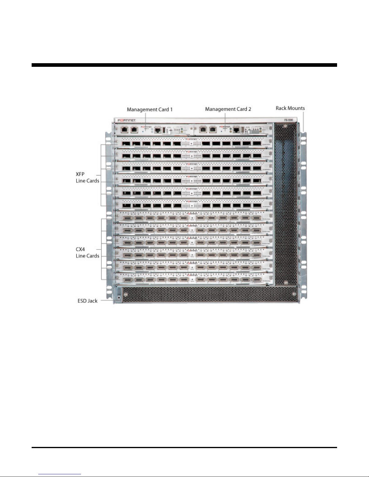
2.1 Front of Chassis
Fully loaded FortiSwitch-1000 chassis with dual management cards and a combination of XFP
line cards and CX4 line cards.
– 8 –
Page 9
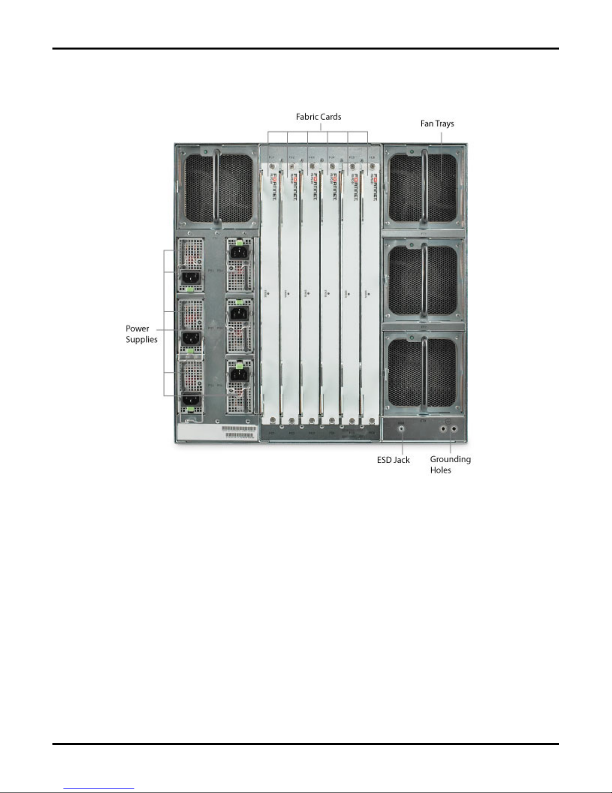
2.2 Back of Chassis
The back of the FortiSwitch-1000 with the full complement of six power supplies installed. Note
orientation of fan trays and power supplies. The three power supplies on the left are installed
with the release lever side down; the three power supplies on the right are installed with the
release lever side up. Ensure that each supply is correctly oriented.
– 9 –
Page 10

2.3 Management Card
Management Network Port: Ethernet port for out-of-band management of the switch. To
configure the switch via the management network port, an IP address must be configured on the
port by accessing the switch through the serial port or connecting the switch to a network with a
DHCP server.
Config Ethernet Port: This port is reserved for future functionality.
Reset Switch: Recessed switch used to force a reset of the management card without physically
removing the card from the chassis.
Serial Console Port: RS-232 serial port used for direct configuration of the management card by
connection to a laptop or other external control device. The settings for the serial connection are
an initialized baud-rate of 115200, 8 bit, no parity, and no flow control. The table below shows
the pinout of the serial console port connector:
Pin Signal Direction
1 NC Not Connected
2 DTR Output from card
3 TXD Output from card
4 GND
5 GND
6 RXD Input to card
7 DSR Input to card
8 NC Not Connected
External USB Port, Activity Indicator and Stop Switch: These three elements are reserved for
future external USB functionality and are not currently supported. Note: the stop button in this
grouping is currently unsupported and does not reset the management card. To reset the
management card, use the recessed reset switch.
LEDs: For full description of LED states, see Appendix 1: LED States on page 22.
– 10 –
Page 11

2.4 Line Card (CX4)
FS-10G12-CX4 / FS-10G12-CX4-A
Line card with CX4 ports; ports can support either powered (active) cables or passive copper
cables. “Link up” indicators and link activity indicators are located next to each port. For full
description of LED states, see Appendix 1: LED States on page 22.
2.5 Line Card (XFP)
FS-10G12-XFP / FS-10G12-XFP-A
Line card with XFP optical ports, optical transceivers installed; ports can support either SR (FSXFP-10G-SR) or LR (FS-XFP-10G-LR) optical transceivers. The indicator LEDs are identical in
function to those on the CX4 line card, but aggregated in a central panel. For full description of
LED states, see Appendix 1: LED States on page 22.
– 11 –
Page 12

2.6 Fan Tray
FS-1000-FANTRAY
Fan tray, showing release tab and handle for use in removing fan tray in case of a fan failure. For
full description of LED states, see Appendix 1: LED States on page 22.
– 12 –
Page 13

2.7 Power Supply
FS-1000-PWR850
850 watt power supply unit, showing release tab and handle for use in removing power supply in
case of a failure requiring unit replacement (indicated by a solid amber light). For full description
of LED states, see Appendix 1: LED States on page 22. To remov
green release tab toward the center of the unit, then pull on the black handle.
e power supply unit, press the
– 13 –
Page 14

3 Site Preparation
3.1 Safety Considerations
Please see “Appendix 3: Regulatory Compliance and Safety Considerations” on page 27 for
regulatory and safety information.
3.2 Environmental Considerations
The maximum recommended ambient temperature for the FortiSwitch-1000 during operation is
40 degrees C. Please note, though, that in a multi-unit rack assembly, temperatures in the rack
environment can be greater than room ambient: room temperatures below 40 degrees C are
often required.
Rack assembly must be configured to avoid blockage of intake and exhaust registers; a minimum
of 6 inches of clearance is required from the front and rear of the FortiSwitch-1000 to ensure
adequate air flow through the system.
3.3 Rack Requirements
The FortiSwitch-1000 chassis is 19" rack-mountable and occupies 10RU (rack units) of rack
space. It is shipped with rack mounts installed appropriately for front mounting, and includes
additional screw holes to accommodate mid-mounting.
Ensure that adequate racking is available to safely support the chassis with 6" clearance in front
and in back for airflow and cabling. Install chassis supports or shelving in rack before removing
chassis from packing crate.
3.3.1 Switch Dimensions and Weight
Height: 44.45 cm (17.50 inches)
Depth: 71.12 cm (28 inches)
Width: 43.82 cm (17.25 inches)
Weight: 56 to 85.5 Kg (125 to 188.5 lbs) depending on configuration; a fully-loaded chassis with
12 XFP line cards weighs approximately 85.5 Kg (188.5 lbs).
3.4 Power Requirements and Redundancy
3.4.1 Power Overview
Please consult “Power” on page 30 before connecting the switch to an AC power source. Fortinet
recommends using 200 to 240 V AC power to accommodate future upgrades which may require
higher power consumption.
– 14 –
Page 15

Each power supply shipped with the FortiSwitch-1000 provides a maximum of 850 W DC power.
To calculate the power draw and circuit breaker requirements for the switch as a whole, limit the
AC current per power supply to 8A for 100-180VAC and 5A for 200-240VAC.
3.4.1.1 Peak Input AC Current per Power Supply
At 120 V AC: 12 A
At 240 V AC: 6 A
3.4.2 Feed-Level Redundancy
For the highest level of power redundancy, the switch must be connected to two independent
sources of AC power. In addition to the primary AC power source, this requires a second feed
from a different power substation or an in-house generator or other grid-independent source of
dependable AC power. Connecting three 850W power supplies to each of the two independent
AC feeds (attached to separate circuit breakers) can provide feed-level redundancy for a subset
of possible switch configurations (those for which N=3 or below – consult “Power Supply-Level
undancy” below).
Red
3.4.3 Circuit Breaker-Level Redundancy
If feed-level redundancy is impossible or unnecessary for your installation, Fortinet recommends
establishing circuit breaker-level redundancy by putting each pair of power supplies on a separate
circuit-breaker. For configurations where N=4 or below, this allows six power supplies to provide
uninterrupted power to the switch in the event that a single power cord is disconnected or a single
circuit-breaker is tripped.
3.4.4 Power Supply-Level Redundancy
The minimum recommended level of redundancy is provided by ensuring the presence of N+1
power supplies as detailed in the chart below. Assuming constant AC power from the power strip,
this provides uninterrupted power to the switch in the event that a single power supply fails.
The following chart shows the maximum number of line cards supported by various numbers of
power supplies. Recommended minimum power supply configuration is N+1, where N is equal to
the minimum number of power supply units required to power the chassis for a given
configuration.
850 W Power
Supplies Required
N=1
N=2
N=3
N=4
CX4 Line Cards
Using Passive
Cables
Maximum Number of Line Cards Supported
CX4 Line
Cards Using
Active Cables
0 0 0 0
4 3 3 3
10 7 7 6
12 12 11 10
XFP Line
Cards, SR
Modules
XFP Line
Cards, LR
Modules
– 15 –
Page 16

N=5
N=6
12 12 12 12
12 12 12 12
– 16 –
Page 17

4 Unpacking and Mounting the Switch
4.1 Unpacking the Switch
NOTE: Prior to touching or handling the switch or any of its components, ensure that the
equipment is protected against all forms of electrostatic discharge (ESD). Personnel must ground
themselves before handling the switch or its components, and Fortinet recommends that all cards
should be handled using anti-static bags.
4.1.1 Prepare Rack
The packing crate in which the FortiSwitch-1000 is shipped is the safest place to store the switch
while preparing for installation. Ensure that chassis supports or shelving are properly installed
and secured before removing the switch from its crate; if third party or aftermarket shelving is
unavailable, Fortinet recommends use of the support brackets included in the shipping crate.
4.1.1.1 Support Brackets
Support brackets are shipped with the FortiSwitch-1000 to facilitate the mounting of the switch,
packed in the gap above the crate base (see below). They are designed to support the weight of
the chassis during mounting, and are attached at the front and rear of the shelving space (not on
the sides).
4.1.2 Remove Cover
The crate cover is held in place by four hinged clasps; unfasten them by turning the handle
counterclockwise to disengage the clasp, then pulling the clasp away from the crate cover. Once
the clasps are unfastened, lift the cover straight up until it is clear of the chassis and set it aside.
4.1.3 Lift Switch Free from Crate Base
Fortinet strongly recommends using a mechanical lift to install the switch in the rack. Before a lift
can be used, though, the switch must be manually lifted to free it from the crate base. Lift the
– 17 –
Page 18

switch straight up to clear the lip on the base, then position it to be mechanically lifted into
position in the rack.
CAUTION: There are sharp metal components inside the chassis; be sure to wear adequate
hand protection and grip carefully. A fully-loaded switch weighs over 188 lbs.; Fortinet
recommends removing components as needed to reduce weight before lifting and using a
minimum of four people to manually lift the switch. If you remove cards from the switch, take
necessary precautions to protect them against electrostatic discharge (ESD) as described above.
4.2 Mounting the Switch
4.2.1 Position and Attach the Switch
Use a mechanical lift to position the switch on the chassis supports or shelving. Align the rackmount holes with the rail holes, insert mounting screws and tighten.
4.2.2 Establish Ground and Connect to AC Power
Before connecting the power supplies to AC power, establish the ground for the switch by
connecting a grounding wire to the grounding attachment point located on the back of the chassis
and connecting the other end to an appropriate grounding attachment point in your facility. The
grounding attachment holes accommodate 1/4"-20 thread screws and are spaced for a dual hole
ground lug on 5/8" centers.
Use only copper conductors for supply and ground wiring.
4.3 XFP Pluggable Transceivers
The pluggable transceivers supplied with XFP line cards are Class 1 LASER devices. They are
theoretically eye-safe without protection, but Fortinet strongly recommends avoiding looking into
the transceivers or into the end of an attached fiber optic cable when the switch is powered. For
further safety information, please consult “LASER Safety” on page 29.
4.3.1 Further Considerations in Handling XFP Transceivers
The transceivers are very sensitive to static shock damage. Always take adequate precautions
against ESD when handling transceivers.
Never try to force a transceiver out once it is inserted into the line card; transceivers have a
release button or lever which must be actuated before attempting to remove the transceiver.
– 18 –
Page 19

5 Configuring the IP Address and
Default Gateway
In order to configure or otherwise manage the FortiSwitch-1000 without the use of a console
directly attached to the serial console port, an IP address must first be configured on the
management card of the switch to allow access via telnet or SSH session.
5.1 Initial Switch Configuration
5.1.1 Connecting to the Serial Port
Until inband or out-of-band management has been established, initial configuration of the switch
must be performed via the serial port (see the management card illustration on page 10). The
serial cable provided with the switch can connect to a standard DB9 serial port on an older PC;
newer computers may require a USB-serial converter (not included).
The settings for the serial connection are an initialized baud-rate of 115200, 8 bit, no parity, and
no flow control. The table below shows the pinout of the serial console port connector:
Pin Signal Direction
1 NC Not Connected
2 DTR Output from card
3 TXD Output from card
4 GND
5 GND
6 RXD Input to card
7 DSR Input to card
8 NC Not Connected
5.2 Management and IP Addressing Options
5.2.1 Inband vs. Out-of-Band Management
The FortiSwitch-1000 may be managed inband or out-of-band, with out-of-band management
typically being performed via the management network port on the management card. Fortinet
recommends use of out-of-band management to allow uninterrupted access to the switch in the
event of a broadcast storm.
– 19 –
Page 20

5.2.2 DHCP vs. Static IP Addressing
The FortiSwitch-1000 is configured to seek an IP address via DHCP by default, but a static IP
address can also easily be manually configured on the switch. If the network administrator
wishes to always access the switch by a consistent IP address, in switches with dual
management cards Fortinet recommends manually configuring the same static management IP
address on both cards. Because only one management card is active at a time, the duplicate
address does not cause an addressing conflict, and in the event of a switchover to the standby
management card the switch may still be accessed using the same IP address, even if the switch
is then rebooted with the second management card remaining active.
5.2.2.1 Management Card Switchover
During a switchover (when the standby management card becomes the active card without
rebooting, through either failover or use of the switchover command), the IP address of the
newly active card will depend on the configuration of the second management card.
Static (Manually Configured): If the IP addresses of both management cards are fixed, then the
standby card will take over the IP address of the active card when they switch roles; the IP
address remains the same even if the cards have different static IP addresses. On reboot,
however, the second management card will be reset to its manually configured, fixed IP address.
If the operator wishes to guarantee access to the switch by a single IP address under all
circumstances, both management cards should be configured with the same static IP address.
Dynamic (DHCP): If the IP addresses of both management cards are assigned dynamically by
DHCP, then the standby card will take the next available IP address from the DHCP server in the
event of a switchover. The management IP address for the switch will therefore be different after
switchover.
5.3 IP Address Configuration
5.3.1 Configuring an IP Address via DHCP
5.3.1.1 Setting the IP Address
By default, each FortiSwitch-1000 management card will attempt to acquire an IP address
automatically via DHCP once the switch is running and a network cable is plugged into the
management network port of the management card. If the management network port of the
active management card is connected to a network which includes a functioning DHCP server, an
IP address for the management network port should be automatically configured on the active
management card.
5.3.1.2 Finding the Assigned IP Address
If the DHCP-assigned management IP address for the management card cannot be easily
deduced from the network, it can be found through the CLI:
Log into the switch (see “Logging in to the Switch” below).
Type sho
service port, including the management IP address.
w mgmt-ip service-port to display configuration information for the management
5.3.2 Manually Configuring a Static IP Address
The process below assumes that the operator is configuring the switch for out-of-band
management. Inband management is disabled on the switch by default; information on
– 20 –
Page 21

configuring inband management can be found in the CLI Command Reference Guide under in
section 4.2.16 (“mgmt-ip inband”).
5.3.2.1 Logging in to the Switch
The switch is factory configured with a single administrator-level login account. To log in to the
switch for the first time with administrative privileges:
1. Ensure that the switch has been turned on and allowed to boot up.
2. Connect a console to the active management card via the serial console port (see
“Management Card” on page 10). The settings for the serial connection are an initialized baudrate of 1152
3. Type admin for the user name, and enter for the password (the default account has no
associated password).
00, 8 bit, no parity, and no flow control.
5.3.2.2 Setting the IP Address, Netmask and Gateway
Once logged in to the CLI, use the following steps to enter static IP address details for the
management network port:
Type enable to enter Enable Mode.
Type config to enter Config Mode.
Type mgmt-ip service-port ip <ip_address><netmask><gateway> where <ip_address> is the
static IP address you wish to configure on the active management card’s management network
port for out-of-band management of the switch.
5.3.2.3 Configuring an IP Address on the Second Management Card
When configuring IP addresses statically on a switch with dual management cards, the second
card can be configured with the same IP address as the first. Once the above steps have been
followed to log into the switch and configure an IP address on the first management card, follow
the following steps to configure the second card:
From Enable Mode, type switchover. This transfers switch management to the secondary
management card and allows its direct configuration.
Type config to enter Config Mode.
Type mgmt-ip service-port ip <ip_address><netmask><gateway> where <ip_address> is the
static IP address you wish to configure on the secondary management card’s management
network port for out-of-band management of the switch. Because the management cards never
operate simultaneously, this may be the same IP address as for the primary management card.
Type switchover again to return control of the switch to the primary management card.
Note: the same result can be achieved by copying the entire configuration of the active
management card to the standby management card.
– 21 –
Page 22

6 Appendix 1: LED States
LED State Meaning State Meaning Notes
Mgmt Card
ACT In current versions of the
FortiSwitch, the ACT light is always
off. Future functionality will use
this light to indicate state and
activity of the external USB card.
ACT
MGR
MC green All installed management
FC green All fabric cards are running
LC green All line cards are running
PWR green All power supplies
FAN green All fans are running
green This is the active
management card.
cards up and running.
normally.
normally.
powered and running
normally.
normally.
off This is the
yellow One or both
yellow One or more
yellow One or more line
yellow One or more
off One or more fans
standby
management
card.
management
cards are not up
and running.
fabric cards are
not running
normally.
cards are not
running normally.
power supplies
not running
normally.
not running
normally.
In a system with only one
management card the MC light
indicates the state of that card.
If the management card's FC light
is yellow, check the LEDs on the
individual fabric cards to identify
the source of the problem.
If the management card's LC light
is yellow, check the LEDs on the
individual line cards to identify the
source of the problem.
If the management card's PWR
light is yellow, check the LEDs on
the individual power supplies to
identify the source of the problem.
If the management card's FAN
light is off, check the LEDs on the
individual fan trays to identify the
source of the problem.
– 22 –
Page 23

LED State Meaning State Meaning Notes
(Mgmt Card, cont.)
ENV green All thermal
yellow One or more
sensors within
range.
SUMMARY
(green)
on All is well. The
SUMMARY light is
Summary lights are mutually
green if everything
else is green.
SUMMARY
(yellow)
LNK green Connection is
on Something is
wrong.
off The link is not up.
made, synched
and ready.
ACT blinking
Activity on the link. off No traffic present. Green ACT LED will be constantly
green
STATUS green Line card
yellow Line card not
functioning
normally.
thermal sensors
out of range.
Line Card
functioning
normally.
exclusive; one is on, the other is
off; if both are off, it usually means
no power is being supplied to the
system.
on at high data rates.
Check here to see which line card
is the problem if the management
card LC LED is yellow.
STATUS green Fabric card
functioning
normally.
(LED) green All fans in tray
running normally.
Fabric Card
yellow Fabric card not
functioning
normally.
Fan Tray
yellow One or more fans
in tray not running
normally.
Check here to see which fabric
card is the problem if the
management card FC LED is
yellow.
– 23 –
Page 24

LED State Meaning State Meaning Notes
Power
Supply
(LED)
solid
green
Main output (12V
DC) is available
from this unit.
blinking
green
AC power is
present; standby
output (3.3V DC) is
on, main output is
off.
off No AC power is
being supplied to
the unit.
solid
amber
Unit has failed
and must be
replaced due to
fan failure,
overtemperature
protection (OTP),
or standby output
overcurrent or
undervoltage
protection
(OCP/UVP).
blinking
amber
Main output
failure due to
OCP, OVP or
UVP.
– 24 –
Page 25

7 Appendix 2: Updating the System
Image
The software image of the most recent approved GA software at ship time is provided on a USB
flash drive already installed in the management card, so installation of an updated system image
is only necessary if you need features which are not available in the shipped version of the
software.
7.1 Image Update Procedure
7.1.1 Download Image
Contact Fortinet Technical Support to download the appropriate system images to a local FTP or
TFTP server on your network. Fortinet recommends installing the images onto the switch from a
local server on your network to reduce the number of hops in the final installation process and
ensure higher data integrity in the images.
Note: there are separate system images for management, line and fabric cards; all system
images in use on a single chassis must be from the same software build, so be sure to update all
three at the same time.
7.1.2 Load Images onto Switch
If using FTP, type the ftp command in File Mode to open a connection to the local FTP server
onto which you’ve downloaded the images and copy the images to the switch using standard FTP
commands.
If using TFTP, use the tftp get command to copy the images from the local TFTP server onto
which you’ve downloaded the images as follows:
1. Access the CLI with admin privileges, and type enable to access Enable Mode.
2. Type file to access File Mode.
3. To load each image from your TFTP server, type tftp get
<ip_address>:/<file_path>/<file_name> [target_file] where <ip_address>:/<file_path> is the IP
address and file path of the local FTP server location of the new image file, <file_name> is the
name of the new image and <target_file> is the file name on the FortiSwitch-1000 management
card.
4. Repeat step three for each of the remaining images. Be sure to update your system with
system images from the same build for the management card, fabric cards and line cards.
7.1.3 Set System Images
Set the newly downloaded images as the system images for all cards by using the system image
command.
1. From File Mode, type system image mgmt all <file_name> (where <file_name> is the name
of the new management card system image) to set the system image for both management cards.
(In a non-redundant chassis, use system image mgmt 1 instead.)
– 25 –
Page 26

2. Type system image fabric all <file_name> (where <file_name> is the name of the new fabric
card system image) to set the system image for all fabric cards.
3. Type system image line all <file_name> (where <file_name> is the name of the new line card
system image) to set the system image for all line cards.
7.1.4 Reload System
Finish the process by resetting the switch.
1. From File Mode, type exit to access Enable Mode.
2. Type reload to reset the switch without power cycling. This command terminates all network
connections and loads the settings from the startup-config file.
– 26 –
Page 27

8 Appendix 3: Regulatory Compliance
and Safety Considerations
8.1 Agency Approvals
8.1.1 Safety
UL 60950-1 / CSA 22.2 No. 60950-1; Safety of Information Technology Equipment
EN / IEC 60950-1; Safety of Information Technology Equipment
EN 60825-1 - Safety of Laser Products - Part 1; Equipment Classification. Requirements and
User's Guide
EN 60825-2; Safety of Laser Products - Part 2; Safety of Optical Fiber Communication Systems
8.1.2 EMI
FCC Part 15 Class A
ICES-003 Class A
EN 300 386 Class A
EN 55022 Class A
VCCI Class A
EN 61000-3-2
EN 61000-3-3
8.1.3 Immunity
EN 300 386
EN 55024
EN 61000-4-2; Electrostatic Discharge (ESD) Immunity
EN 61000-4-3; Radiated RF Immunity
EN 61000-4-4; Electrical fast Transients (EFT) Immunity
EN 61000-4-5; Electrical Surge Immunity
EN 61000-4-6; Conducted Immunity
EN 61000-4-8; Magnetic Field Immunity
EN 61000-4-11; Power Voltage Dips Immunity
– 27 –
Page 28

8.2 EMC Compliance Statements
8.2.1 United States
This equipment has been tested and found to comply with the limits for Class A digital devices,
pursuant to part 15 of the FCC Rules. These limits are designed to provide reasonable protection
against harmful interference when the equipment is operated in a commercial environment. This
equipment generates, uses, and can radiate radio frequency energy and, if not installed and used
in accordance with the instruction manual, may cause harmful interference to radio
communications. Operation of this equipment in a residential area is likely to cause harmful
interference in which case the user will be required to correct the interference at their own
expense. Changes or modifications to this equipment not expressly approved by the party
responsible for compliance to FCC part 15 could void the user's authority to operate the
equipment.
8.2.2 European Union
This is a Class A product. In a domestic environment this product may cause radio interference in
which case the user may be required to take adequate measures.
8.2.3 Canada
This Class A digital apparatus complies with Canadian ICES-003. Cet appareil numérique de la
classe A est conforme à la norme NMB-003 du Canada.
8.3 General Safety Guidelines
8.3.1 Installation Environment
The maximum recommended ambient temperature for the FortiSwitch-1000 during operation is
40 degrees C.
Since a chassis can be installed into a multi-unit rack assembly, the operating ambient
temperature of the rack environment may be greater than room ambient. Therefore, consideration
should be given to installing the equipment in an environment compatible with the maximum
recommended ambient temperature of 40 deg C.
Installation of the chassis in a rack assembly should be such that the amount of air flow required
for safe operation of the equipment is not compromised (that is, no blockage of intake or exhaust
registers). A minimum of 6 inches of clearance is required from the front and rear of the
FortiSwitch-1000 to ensure adequate air flow through system.
8.3.2 Mechanical
Mounting of the FortiSwitch-1000 in the rack assembly should be such that a hazardous condition
is not achieved due to uneven mechanical loading.
– 28 –
Page 29

8.3.3 Electrical Rating
The FortiSwitch-1000’s electrical ratings should be considered when connecting to the power
supply circuits. Consideration must be given to the effect that overloading of circuits may have on
overcurrent protection and supply wiring.
8.3.4 Grounding
Reliable earthing (grounding) of the FortiSwitch-1000 chassis through the protective earthing
terminal(s) should be maintained.
8.3.5 Metallic Interfaces
FortiSwitch-1000 metallic interfaces are suitable for connection to intrabuilding or non-exposed
wiring or cabling only.
8.3.6 Fuse Replacement
Although FortiSwitch-1000 field-replaceable units (cards, power supplies and fan trays) are
provided with fuses and holders, Fortinet does not recommend replacement of damaged or blown
fuses. It is recommended instead that the entire FRU be returned to Fortinet for
repair/replacement if found to be non-functional.
8.3.7 LASER Safety
CLASS 1 LASER PRODUCT: FortiSwitch-1000 circuit boards may be equipped with optical
communication transmitters which have been evaluated and found to be in compliance with
requirements found within 21 CFR (FDA-CDRH) and EN 60825-1 for Class 1 laser devices.
WARNING: While Class 1 laser products are considered to be “eye safe” without the need for
additional protection, when working around the circuit boards, the following general safety
guidelines should be observed to reduce the risk of eye injury:
Do not look or stare into unterminated optical fiber ports or at fibers that are connected to a
source.
Do not examine unterminated optical fiber ports or optical fibers that are connected to a source
with optical instruments. The use of optical instruments (e.g. magnifying glass) with this product
may increase eye hazard.
Adjustments/settings, maintenance, operational parameters and procedures other than those
specified and allowed herein and on the rating plate of the FortiSwitch-1000 may result in
increased eye hazard.
Do not attempt to perform any repair or maintenance on optical communications components.
Repairs and maintenance outside that which is allowed herein must be performed only by an
authorized repair facility.
8.3.8 Restricted Access Location
The FortiSwitch-1000 is intended to be installed only in a RESTRICTED ACCESS LOCATION.
A RESTRICTED ACCESS LOCATION is defined as an area where access can be gained only by
SERVICE PERSONNEL who have been instructed about the reasons for the restrictions applied
to the location and about any precautions that must be taken.
– 29 –
Page 30

RESTRICTED ACCESS LOCATIONS can be accessed only through the use of a tool or lock and
key or other means of security, and are controlled by the authority responsible for the location.
SERVICE PERSONNEL are defined as persons having appropriate technical training and
experience necessary to be aware of hazards to which they are exposed in performing a task and
of measures to minimize the danger to themselves or other persons.
8.3.9 Power
Each chassis has a maximum of six AC power supply connections. A minimum of 5 power
supplies and 3 separate branch circuits are required when input voltage range is 100-180 VAC.
A minimum of 5 power supplies and 2 branch circuits are required when input voltage range is
200-240 VAC. Each branch circuit over-current protection must be Listed 20 Amp for North
America or European Union (EU) Installation. A readily accessible disconnect device that is
suitably approved and rated should be incorporated in the facility wiring. All power connections
must be removed to completely de-energize the unit.
Before conducting non-operational work or maintenance on the FortiSwitch-1000, completely
remove all power from the unit. The circuit breakers feeding the chassis, when opened, will deenergize circuitry beyond the breakers.
When performing work/maintenance on the FortiSwitch-1000 during operation, SERVICE
PERSONNEL should use caution as there are Hazardous Energy levels present within the
chassis.
8.3.10 Supply and Chassis Ground Wiring
Use only copper conductors for supply and ground wiring.
The power supplies are designed to accept UL/CSA rated power cords with IEC 60320 C13 plugs.
Specific conductor size and type should be in accordance with NEC/CEC requirements.
8.4 General Operational and Maintenance
Guidelines
The following guidelines are designed to help ensure the safety of the people working on or
around the FortiSwitch-1000 (such as technicians or installers) and are also designed to protect
the routing equipment.
Installation of the FortiSwitch-1000 should be performed only by a qualified technician.
Do not wear conductive items such as watches, bracelets, rings, or other jewelry when working
with the FortiSwitch-1000.
The installation area should be kept dust-free at all times.
Never attempt to lift an object that may be too heavy.
Keep tools and other equipment out of walkways where people could trip on them.
8.4.1 Electrical Safety
WARNING: Disconnect all power supplies before performing non-operational servicing.
The FortiSwitch-1000 is designed to be upgraded while the system is operational. Performing
upgrades on the FortiSwitch-1000 therefore entails working with live voltage. The following
– 30 –
Page 31

guidelines are designed to help ensure the safety of technicians working with the equipment,
prevent occurrences of electric shock, and to mitigate the risk of damaging the equipment:
Know the location of the emergency power-off switch at the facility before work on the
FortiSwitch-1000 begins. The readily accessible disconnect device shall be incorporated in the
building installation wiring.
Never work alone when connecting power cables to the FortiSwitch-1000.
Examine all equipment and components for possible hazards, such as moistness, loose cabling,
or improper grounding.
Never install damaged equipment.
Never assume a circuit is disconnected from the power source. Always verify that a circuit has
been disconnected before work begins.
8.4.2 ESD
The FortiSwitch-1000 is sensitive to electrostatic discharge (ESD). It is important to take the
necessary precautions before working on a system. The following guidelines will help reduce the
risk of an ESD event damaging the electronics of a system:
Make sure the chassis is properly grounded before handling any electronic components (the
FortiSwitch-1000 is provided with attachment points on the rear of the chassis for the connection
of a grounding cable).
Always wear an ESD-preventative wrist strap.
Make sure the wrist strap makes adequate contact with your skin. An ESD wrist strap tester is
recommended.
Make sure the other end of the wrist strap is connected to one of the standard ESD jacks on the
front or rear of the chassis.
– 31 –
 Loading...