

Page 1
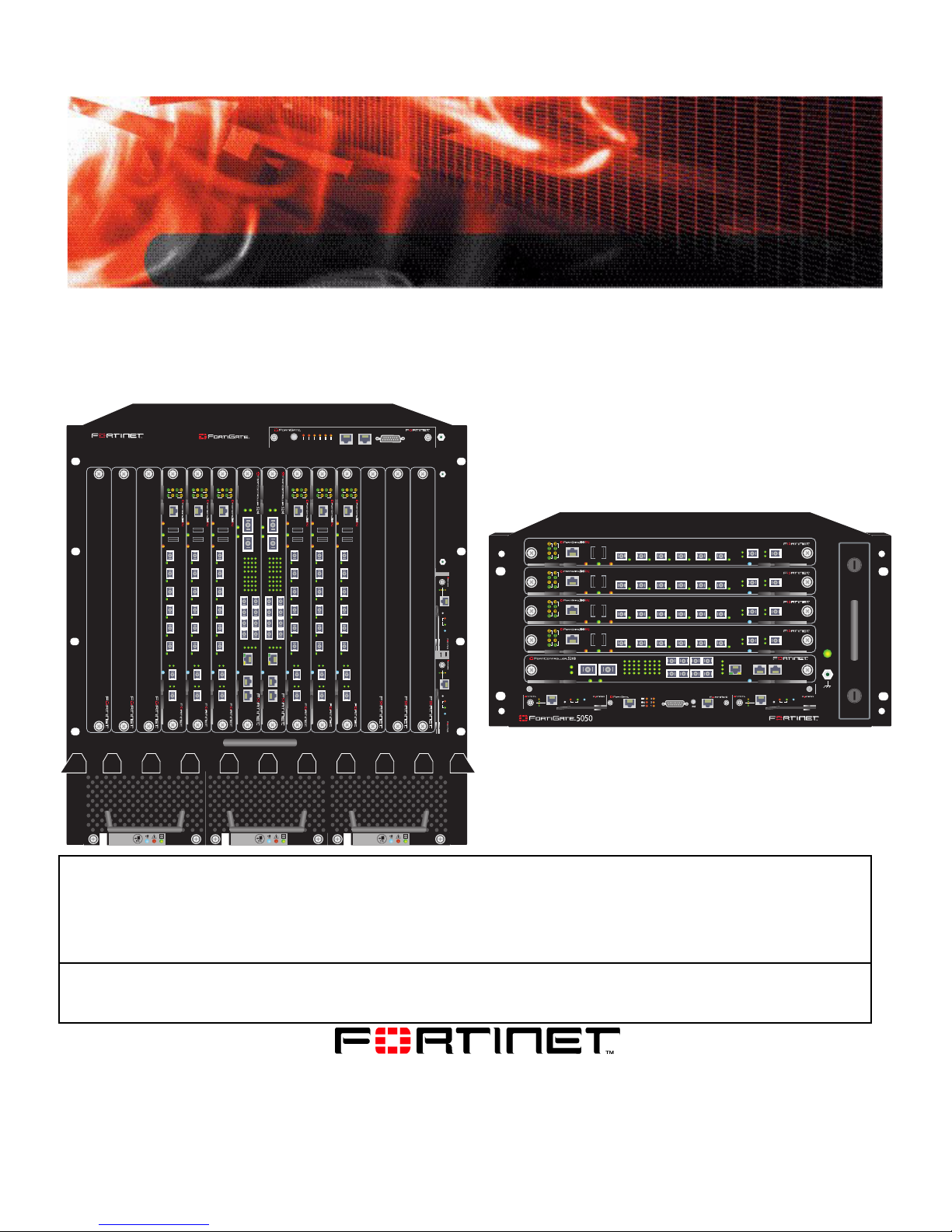
FortiGate-5005-DIST Security System
5140SAP
5140
T
SE
RE
1311975312468101214
D
C
1/2 3/4 D15/D16 C15/C16
X 1
234
678
101112
141516
234
678
101112
141516
MANAGEMENT
COM 1 COM 2
STATUS
X 1 X 2
PAYLOAD OPERATION
1
5
DATA CONTROL
9
13
1
5
9
13
123
IPM
X 2
X 1
X 1 X 2
10/100/1000 MBPS ETHERNET ACTIVITY
1
234
5
678
DATA CONTROL
101112
9
D
D
13
141516
1
234
5
678
101112
9
C
C
13
141516
1/2 3/4 D15/D16 C15/C16
123
4
MANAGEMENT
COM 1 COM 2
LINK
CONSOLE
OOS ACC STATUS
IPM
LINK
ACT
FABRIC
BASE
CONSOLE
OOS ACC STATUS
IPM
LINK
LINK
LINK
ACT
ACT
FABRIC
BASE
CONSOLE
OOS ACC STATUS
USB USB
3 412 56
3 412 56
IPM
78
LINK
LINK
ACT
ACT
ACT
FABRIC
BASE
CONSOLE
OOS ACC STATUS
USB USB
USB USB
3 412 56
IPM
78
78
X 2
STATUS
PAYLOAD OPERATION
10/100/1000 MBPS ETHERNET ACTIVITY
D
C
4
IPM
L
R
A
R
C
JO
INO
SER1
A
RITI
U
M
M
C
LINK
LINK
ACT
ACT
FABRIC
BASE
CONSOLE
OOS ACC STATUS
USB USB
3 412 56
IPM
78
SERIAL 1 SERIAL 2 ALARM
3
R2
SE
SER
U
U
LINK
LINK
ACT
ACT
FABRIC
BASE
CONSOLE
OOS ACC STATUS
USB USB
3 412 56
IPM
78
LINK
ACT
ACT
FABRIC
BASE
USB USB
3 412 56
78
Getting Started
ACT
LINK
ACT
5
LINK
ACT
LINK
5000SM
ETH1
ETH0
10/100
10/100
link/Act
link/Act
ETH0
Service
RESET
STATUS
Hot Swap
12
5000SM
ETH1
ETH0
10/100
10/100
link/Act
link/Act
ETH0
Service
RESET
STATUS
Hot Swap
ACT
4
LINK
ACT
LINK
ACT
LINK
3
ACT
LINK
ACT
2
LINK
1
5000SM
10/100
SMC
link/Act
ETH1
10/100
ETH0
link/Act
2
USB USB
BASE
FABRIC
CONSOLE
OOS ACC STATUS
USB USB
BASE
FABRIC
CONSOLE
OOS ACC STATUS
USB USB
BASE
FABRIC
CONSOLE
OOS ACC STATUS
USB USB
BASE
FABRIC
CONSOLE
OOS ACC STATUS
X 1 X 2
X 1
X 2
PAYLOAD OPERATION
STATUS
ETH0
Service
STATUS
Hot Swap
RESET
1
2
3
4
10/100/1000 MBPS ETHERNET ACTIVITY
SERIAL
1
DATA CONTROL
9
5
13
10
6
14
11
7
15
D
12
8
16
D
5050SAP
1
2
3
4
3 412 56
3 412 56
3 412 56
3 412 56
9
5
13
10
6
14
1/2 3/4 D15/D16 C15/C16
11
7
15
C
12
8
16
C
ALARM
78
IPM
78
IPM
78
IPM
78
IPM
1
MANAGEMENT
COM 1 COM 2
2
3
4
IPM
5000SM
10/100
ETH0
Service
link/Act
ETH1
SERIAL
10/100
2
ETH0
link/Act
POWER
SMC
STATUS
Hot Swap
RESET
1
FILTER
0
FAN TRAY FAN TRAYFAN TRAY
12
This FortiGate-5005-DIST Security System Getting Started describes how to install FortiGate-5005-DIST security
system hardware components and how to configu re a FortiGate-5005-DIST system onto your network.
The most recent versions of this and all FortiGate-5000 series documents are available from the FortiGate-5000
page of the Fortinet Technical Documentation web site (http://docs.forticare.com).
Visit http://support.fortinet.com to register your FortiGate-5005-DIST Security System. By r egistering you can receive
product updates, technical support, and FortiGuard services.
www.fortinet.com
FortiGate-5005-DIST Security System Getting Started
01-30000-0414-20070615
Page 2

Warnings and cautions
Only trained and qualified personnel should be allowed to install or maintain FortiGate-5000 series
equipment. Read and comply with all warnings, cautions and notices in this document.
CAUTION: Risk of Explosion if Battery is replaced by an Incorrect Type. Dispose of Used Batteries According
!
to the Instructions.
Caution: You should be aware of the following cautions and warnings before installing FortiGate-5000 series
!
hardware
• Turning off all power switches may not turn off all power to the FortiGate-5000 series equipment.
Except where noted, disconnect the FortiGate-5000 series equipment from all power sources,
telecommunications links and networks before installing, or removing FortiGate-5000 series
components, or performing other maintenance tasks. Failure to do this can result in personal injury or
equipment damage. Some circuitry in the Fort iGa te-5000 series equipment may continue to operate
even though all power switches are off.
• An easily accessible disconnect device, such as a circuit breaker, should be incorporated into the data
center wiring that connects power to the FortiGate-5000 series equipment.
• Install FortiGate-5000 series chassis at the lower positions of a rack to avoid making the rack top-heavy
and unstable.
• Do not insert metal objects or tools into open chassis slots.
• Electrostatic discharge (ESD) can damage FortiGate-5000 series equipment. Only perform the
procedures described in this document from an ESD workstation. If no such station is available, you
can provide some ESD protection by wearing an anti-static wrist or ankle strap and attaching it to an
ESD connector or to a metal part of a FortiGate chassis.
• Some FortiGate-5000 series component s may overload your supply circuit and imp act your overcurrent
protection and supply wiring. Refer to nameplate ratings to address this concern.
• Make sure all FortiGate-5000 series components have reliable grounding. Fortinet recommends direct
connections to the branch circuit.
• If you install a FortiGate-5000 series component in a closed or multi-unit rack assembly, the operating
ambient temperature of the rack environment may be greater than room ambient. Make sure the
operating ambient temperature does not exceed the manufacturer's maximum rated ambient
temperature.
• Installing FortiGate-5000 series equipment in a rack should be such that the amount of airflow required
for safe operation of the equipment is not compromised.
• This equipment is for installation only in a Restricted Access Location (dedicated equipment room,
service closet or the like), in accordance with the National Electrical Code.
• Per the National Electrical Code, sizing of a Listed circuit breaker or branch circuit fuse and the supply
conductors to the equipment is based on the marked inpu t current rating. A p roduct with a marked input
current rating of 25 A is required to be placed on a 40 A branch circuit. The supply conductors will also
be sized according to the input current rating and also derated for the maximum rated operating
ambient temperature, Tma, of the equipment.
• FortiGate-5000 series equipment shall be installed and connected to an electrical supply source in
accordance with the applicable codes and re gu la tio ns for the location in which it is installed. Particular
attention shall be paid to use of correct wire type and size to comply with the applicable codes and
regulations for the installation / location. Connection of the supply wiring to the terminal block on the
equipment may be accomplished using Listed wire compression lugs, for example, Pressure Terminal
Connector made by Ideal Industries Inc. or equivalent which is suitable for A WG 10. Par ticular attenti on
shall be given to use of the appropriate compre ss ion too l spe cifie d by the compression lug
manufacturer, if one is specified.
FortiGate-5005-DIST Security System Getting Started
01-30000-0414-20070615
Page 3

Contents
Contents
Warnings and cautions..................................................................................... 2
The FortiGate-5005-DIST Security System...................... 5
Basic FortiGate security system configuration.............................................. 5
FortiController-5208 I/O modules..................................................................... 6
FortiGate-5005FA2 worker modules ................................................................ 7
FortiGate-5005-DIST security system chassis................................................ 7
FortiGate-5140 chassis................................................................................. 8
FortiGate-5050 chassis................................................................................. 8
FortiGate-5005-DIST interface names .... ... ....................................................... 9
Installing hardware components.................................... 11
Getting started................................................................................................. 11
Installing the chassis ...................................................................................... 12
Installing FortiController-5208 modules................................ .... ... ................. 12
Installing FortiController-5208 modules ...................................................... 13
Connecting to the FortiController-5208 CLI or web-based manager .......... 13
Configuring the primary I/O module ............................................................ 14
Installing FortiGate-5005FA2 worker modules ............................................. 15
Installing FortiGate-5005FA2 modules........................................................ 16
Verifying that FortiGate-5005FA2 modules can communicate with the primary
I/O module................................................................................................... 16
Installing DIST firmware on a FortiGate-5005FA2 module ......................... 19
Quick Configuration Guide ............................................. 23
Planning the configuration ............................................................................. 23
NAT/Route mode ........................................................................................ 23
Transparent mode....................................................................................... 24
Choosing the configuration tool.................................................................... 25
Web-based manager................................................................................... 25
Command Line Interface (CLI).................................................................... 25
Factory default settings.................................................................................. 26
Configuring NAT/Route mode........................................................................ 27
Using the web-based manager to configure NAT/Route mode................... 28
Using the CLI to configure NAT/Route mode.............................................. 28
Configuring Transparent mode...................................................................... 29
Using the web-based manager to configure Transparent mode... ... ... .... ... . 30
Using the CLI to configure Transparent mode ............................................ 31
Powering off the FortiGate-5005-DIST system.............................................. 31
FortiGate-5005-DIST Security System Version 3.0 MR2 Getting Started
01-30000-0414-20070615 3
Page 4

Contents
Hardware procedures...................................................... 33
Starting a configured FortiGate-5005-DIST system ........... ... ... ... ... .... ... ... ... . 33
Installing FortiGate-5005-DIST firmware ....................................................... 33
Viewing the currently installed firmware versions....................................... 34
Upgrading I/O module firmware.................................................................. 34
Upgrading worker module firmware installed on the primary I/O module... 36
Upgrading FortiController-5208 NPU firmware............................................. 37
For more information ...................................................... 39
Fortinet documentation .................................................................................. 39
Fortinet Tools and Documentation CD........................................................ 39
Fortinet Knowledge Center ........................................................................ 39
Comments on Fortinet technical documentation ........................................ 39
Customer service and technical support............................... ....................... 39
Register your Fortinet product....................................................................... 39
FortiGate-5005-DIST Security System Version 3.0 MR2 Getting Started
4 01-30000-0414-20070615
Page 5

The FortiGate-5005-DIST Security System Basic FortiGate security system configuration
The FortiGate-5005-DIST Security
System
The FortiGate-5005-DIST security system is very similar to a sing le FortiGate unit,
but with much higher capacity and with support for failover protection and
scalability . The FortiGate-5005-DIST security system consists of a FortiGate-5050
or FortiGate-5140 chassis with one or two Input/Output or I/O modules
(FortiController-5208 modules) and one or more worker modules
(FortiGate-5005FA2 modules running in DIST mode). The I/O modules provide
network connections and distribute traffic to the worker modules. The worker
modules provide FortiGate security system functions including firewall, VPN, IPS,
antivirus, antispam, and so on.
The following topics are included in this section:
• Basic FortiGate security system configuration
• FortiController-5208 I/O modules
• FortiGate-5005FA2 worker modules
• FortiGate-5005-DIST security system chassis
• FortiGate-5005-DIST interface names
Basic FortiGate security system configuration
A basic FortiGate security system consists of a single FortiController-5208
module and four FortiGate-5005 modules installed in a FortiGate-5050 or
FortiGate-5140 chassis (see Figure 1 on page 6 ). This system can be installed in
NAT/Route mode between the Int er ne t and a private network. In this
configuration, the FortiGate-5005-DIST security system can provide FortiGate
services to 10 gigabit traffic passing between the private network and the Internet.
FortiGate-5005-DIST Security System Getting Started
01-30000-0414-20070615 5
Page 6
FortiController-5208 I/O modules The FortiGate-5005-DIST Security System
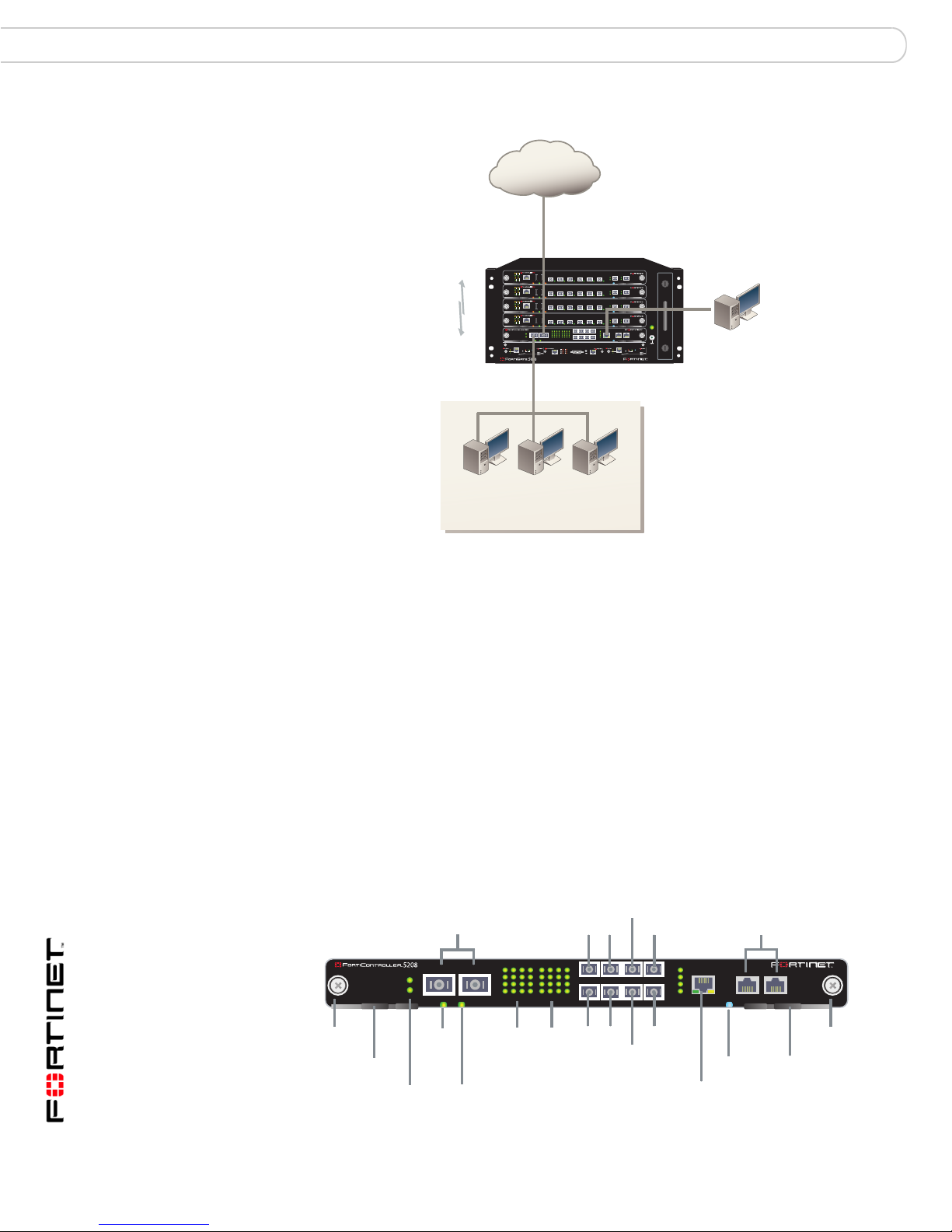
Figure 1: Example basic FortiGate-5005-DIST security system
Internet
X2 (port1_X2)
204.23.1.5
NAT mode policies
controlling 10G traffic
between internal and
external networks.
FortiController-5208 I/O modules
Data flows into and out of the FortiGate-5005-DIST system thro ugh the I/O
modules. The I/O modules are FortiController-5208 modules installed in chassis
slots 1 and 2 in a FortiGate-5050 or FortiGate-5140 chassis. The I/O module
installed in slot 1 is configured as the primar y I/O module. The optional I/O module
installed in slot 2 becomes the secondary I/O module. A FortiGate-5005-DIST
system can include one or two I/O modules.
As the I/O module, the FortiController-5208 provides all FortiGate-5005-DIST
network connections. The FortiController-5208 module provides two 10 gigabit
interfaces and four 1 gigabit interfaces for network traffic. The FortiController-5208
front panel also contains four 1 g igab it interfa ces. Two of these interfaces sup port
inter-chassis HA and two are for future use. Adding a second FortiController-5208
module doubles the number of FortiGate-5005-DIST network interfaces.
ACT
LINK
ACT
FABRIC
5
LINK
ACT
LINK
ACT
FABRIC
4
LINK
ACT
LINK
ACT
FABRIC
LINK
3
ACT
LINK
ACT
FABRIC
2
LINK
1
5000SM
10/100
SMC
link/Act
ETH1
10/100
ETH0
link/Act
2
Internal
network
BASE
CONSOLE
BASE
CONSOLE
BASE
CONSOLE
BASE
CONSOLE
X 1
X 2
ETH0
Service
RESET
FortiGate-5005-DIST
security system in
NAT/Route mode
USB USB
OOS ACC STATUS
USB USB
OOS ACC STATUS
USB USB
OOS ACC STATUS
USB USB
OOS ACC STATUS
DATA CONTROL
9
5
9
1
5
1
13
X 1 X 2
10
6
10
2
6
2
14
11
7
11
3
7
3
15
D
12
8
12
4
8
4
16
D
10/100/1000 MBPS ETHERNET ACTIVITY
PAYLOAD OPERATION
STATUS
5050SAP
SERIAL
STATUS
Hot Swap
1
3 412 56
3 412 56
3 412 56
3 412 56
13
14
1/2 3/4 D15/D16 C15/C16
15
C
16
C
ALARM
78
IPM
78
IPM
78
IPM
78
IPM
1
MANAGEMENT
2
3
4
IPM
5000SM
10/100
link/Act
ETH1
SERIAL
10/100
2
ETH0
link/Act
X1 (port1_X1)
192.168.1.99
POWER
COM 1 COM 2
ETH0
Service
STATUS
Hot Swap
RESET
SMC
1
Management
interface (mng)
Figure 2: FortiController-5208 front panel
SFP Gigabit
Fiber or Copper
Mounting
Knot
Extraction
X1 X2 XFP 10 Gigabit
Fiber or Copper
X 1 X 2
X 1
X 2
STATUS
Status
Lever
Link/
Traffic
Payload
Operation
PAYLOAD OPERATION
DATA CONTROL
5
9
1
5
1
13
10
6
10
2
6
2
14
11
7
11
3
7
3
15
D
12
8
12
4
8
4
16
D
10/100/1000 MBPS ETHERNET ACTIVITY
Link/Traffic
1
9
13
14
1/2 3/4 D15/D16 C15/C16
15
C
16
C
D15
3
C15
C16
42
D16
Management
RJ-45 Ethernet
1
MANAGEMENT
2
3
4
Management
RJ-45 Serial
COM 1 COM 2
IPM
Extraction
IPM
Lever
FortiGate-5005-DIST Security System Getting Started
6 01-30000-0414-20070615
Mounting
Knot
Page 7

The FortiGate-5005-DIST Security System FortiGate-5005FA2 worker modules
FortiGate-5005FA2 worker modules
The FortiGate-5005FA2 security system serves as the worker module for the
FortiGate-5005-DIST security system. Worker modules are identically configured
and administered as a single unit from the primary I/O module. Workers are
typically installed in slots 3 and above, though Fort iGate-5005FA2 security
systems with only one I/O module can also have a worker installed in slot 2.
The worker modules apply all of the FortiGate security system functionality to
traffic passing through the FortiGate-5005-DIST security system. Traffic is
distributed to the worker modules by the I/O modu les . Th e wo rke r mod ule s
perform FortiGate functions such as applying firewall policies, virus scanning, IPS
and routing to distributed traffic.
Figure 3: FortiGate-5005FA2 front panel
Fabric and Base
network activity
LEDs
USB
1 2 3 4 5 6 SPF Gigabit
Fiber or Copper
7 8 SPF Gigabit
Fiber or Copper
Accelerated
ACT
LINK
ACT
LINK
Mounting
Knot
Extraction
FABRIC
Lever
BASE
CONSOLE
RJ-45
Serial
USB USB
OOS ACC STATUS
Out
of
Service
Flash Disk
Access
Status
3 412 56
Link/Traffic
78
IPM
Module
Position
Mounting
Extraction
Lever
Knot
FortiGate-5005-DIST Security System Getting Started
01-30000-0414-20070615 7
Page 8
FortiGate-5005-DIST security system chassis The FortiGate-5005-DIST Security System
FortiGate-5005-DIST security system chassis
FortiGate-5005-DIST security systems can be installed in FortiGate-5050
or FortiGate-5140 chassis.
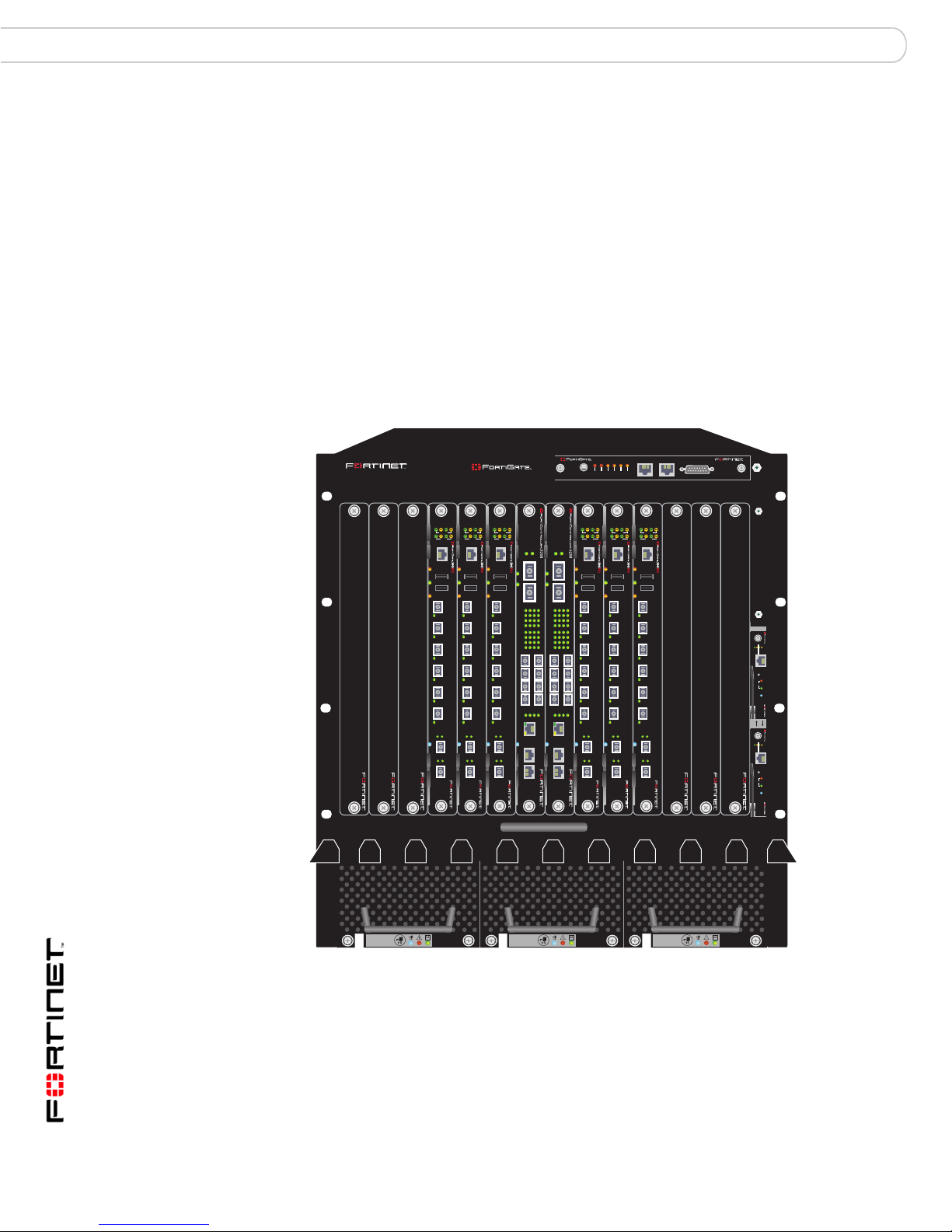
FortiGate-5140 chassis
You can install one or two I/O modules in slo t 1 and 2 of the FortiGate-51 40 ATCA
chassis. You can also install up to 12 worker modules in slots 3 to 14 if two I/O
modules are used, or up to 13 worker modules in slots 2 to 14 if one I/O module is
used. The FortiGate-5140 is a 12U chassis that contains two redu ndant hot
swappable DC power entry modules that connect to -48 VDC Data Center DC
power. The FortiGate -5140 cha ssis also in cludes th ree hot swapp able cooling fan
trays. For details about the FortiGate-5140 chassis see to the FortiGate-5140
Chassis Guide.
Figure 4: FortiGate-5005-DIST components installed in a FortiGate-5140 chassis
5140
5140SAP
CRITICAL
RESET
MINOR
MAJOR
USER2
USER3
USER1
SERIAL 1 SERIAL 2 ALARM
1311975312468101214
LINK
LINK
LINK
LINK
LINK
LINK
LINK
ACT
FABRIC
BASE
CONSOLE
OOS ACC STATUS
3 412 56
IPM
LINK
LINK
ACT
ACT
ACT
FABRIC
BASE
CONSOLE
OOS ACC STATUS
USB USB
USB USB
3 412 56
IPM
78
78
LINK
LINK
ACT
FABRIC
BASE
CONSOLE
OOS ACC STATUS
3 412 56
IPM
ACT
X 2
X 1
STATUS
X 1 X 2
USB USB
PAYLOAD OPERATION
10/100/1000 MBPS ETHERNET ACTIVITY
1
234
5
678
DATA CONTROL
101112
9
D
D
13
141516
1
234
5
678
101112
9
C
C
13
141516
1/2 3/4 D15/D16 C15/C16
123
4
MANAGEMENT
78
IPM
COM 1 COM 2
X 2
X 1
STATUS
X 1 X 2
PAYLOAD OPERATION
10/100/1000 MBPS ETHERNET ACTIVITY
1
234
5
678
101112
9
D
D
13
141516
1
234
5
678
101112
9
C
C
13
141516
1/2 3/4 D15/D16 C15/C16
123
4
MANAGEMENT
IPM
COM 1 COM 2
ACT
FABRIC
BASE
CONSOLE
OOS ACC STATUS
DATA CONTROL
3 412 56
IPM
ACT
ACT
ACT
FABRIC
BASE
CONSOLE
OOS ACC STATUS
USB USB
USB USB
3 412 56
IPM
78
78
LINK
ACT
FABRIC
BASE
CONSOLE
OOS ACC STATUS
3 412 56
IPM
ACT
USB USB
12
78
FILTER
5000SM
ETH1
ETH0
10/100
10/100
link/Act
link/Act
ETH0
Service
RESET
STATUS
Hot Swap
5000SM
ETH1
ETH0
10/100
10/100
link/Act
link/Act
ETH0
Service
RESET
STATUS
Hot Swap
0
FAN TRAY FAN TRAYFAN TR AY
12
FortiGate-5005-DIST Security System Getting Started
8 01-30000-0414-20070615
Page 9
The FortiGate-5005-DIST Security System FortiGate-5005-DIST interface names
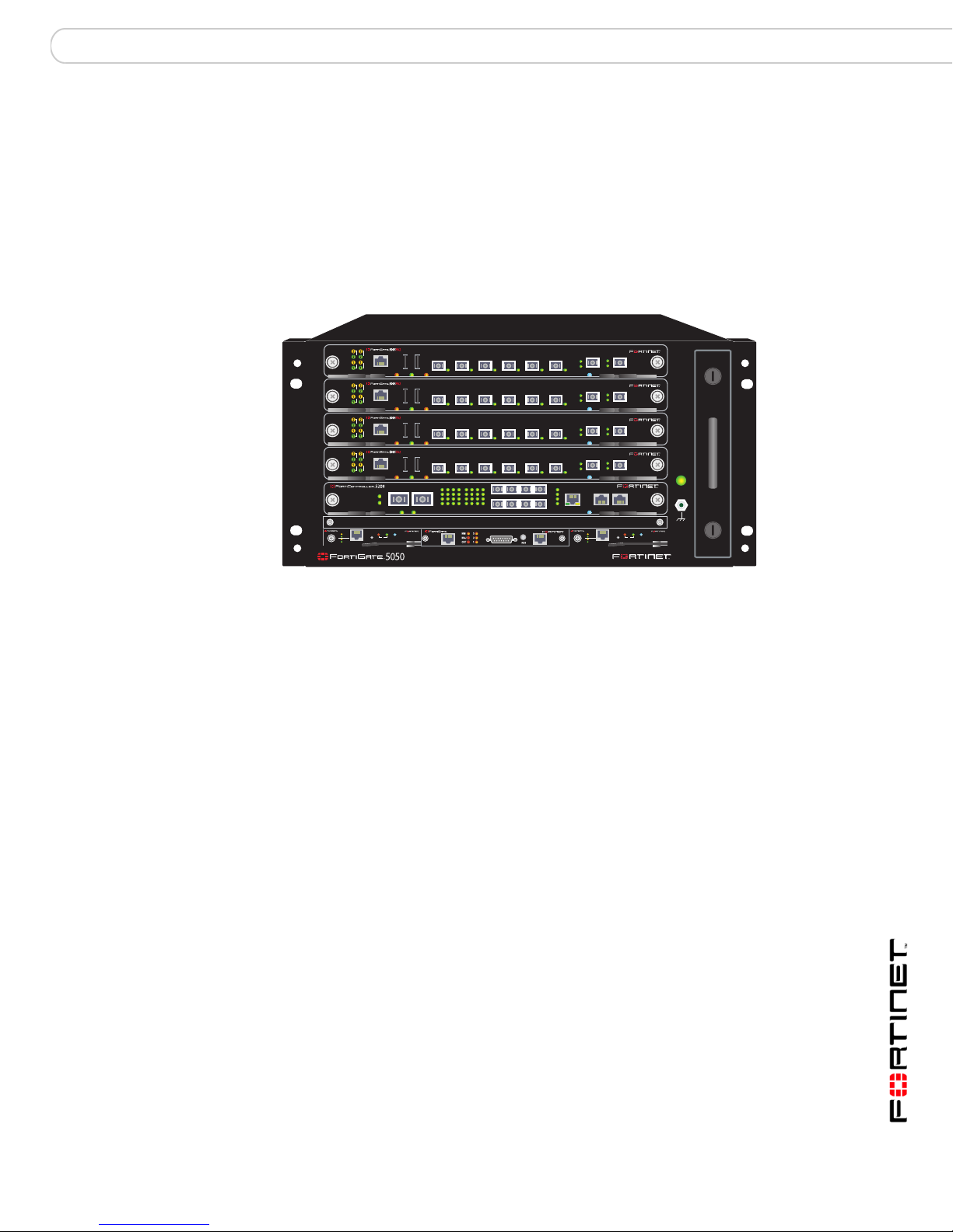
FortiGate-5050 chassis
Y o u can inst all one or two I/O module s in slot 1 and 2 of the F ortiGate-5050 ATCA
chassis. You can also install up to three worker modules in slots 3 to 5 if two I/O
modules are being used, or four worker modules in slots 2 to 5 if one I/O module
is used. The FortiGate-5050 is a 5U chassis that contains two redundant DC
power connections that connect to -48 VDC Data Center DC power. The
FortiGate-5050 chassis also includes a hot swappable cooling fan tray. For details
about the FortiGate-5050 chassis, see the FortiGate-5050 Chassis Guide.
Figure 5: FortiGate-5005-DIST components installed in a FortiGate-5050 chassis
ACT
LINK
ACT
5
LINK
ACT
LINK
ACT
4
LINK
ACT
LINK
ACT
LINK
3
ACT
LINK
ACT
2
LINK
1
5000SM
10/100
SMC
link/Act
ETH1
10/100
ETH0
link/Act
2
USB USB
BASE
FABRIC
CONSOLE
OOS ACC STATUS
USB USB
BASE
FABRIC
CONSOLE
OOS ACC STATUS
USB USB
BASE
FABRIC
CONSOLE
OOS ACC STATUS
USB USB
BASE
FABRIC
CONSOLE
OOS ACC STATUS
X 1 X 2
X 1
X 2
PAYLOAD OPERATION
STATUS
ETH0
Service
RESET
SERIAL
STATUS
Hot Swap
1
DATA CONTROL
5
9
1
5
1
13
6
10
2
6
2
14
7
11
3
7
3
15
D
8
12
4
8
4
16
D
10/100/1000 MBPS ETHERNET ACTIVITY
5050SAP
3 412 56
3 412 56
3 412 56
3 412 56
9
13
10
14
1/2 3/4 D15/D16 C15/C16
11
15
C
12
16
C
ALARM
FortiGate-5005-DIST interface names
The FortiGate-5005-DIST worker web-based manager and CLI use an intern al
naming convention to name FortiGate-5005-DIST interfaces. The interface names
indicate the I/O module containing the interface and also include the I/O module
front panel interface name. The naming convention is:
port<I/O_module_number>_<I/O_module_interface_name>
where:
<I/O_module_number> is 1 for the interfaces of the primary I/O module
installed in chassis slot 1 and 2 for the interfaces of the secondary I/O module
installed in chassis slot 2. The interfaces for the secondary I/O module only
appear in the web-based manager and CLI when a secondary I/O module is
installed.
<I/O_module_interface_name> is the name of the interface as shown on the
FortiController-5208 front panel.
SERIAL
1
2
3
4
2
MANAGEMENT
78
IPM
78
IPM
78
IPM
78
IPM
COM 1 COM 2
IPM
5000SM
10/100
ETH0
Service
link/Act
ETH1
10/100
ETH0
link/Act
POWER
SMC
STATUS
Hot Swap
RESET
1
Table 1 on page 10 shows the relationship between the names of the pr imary and
secondary module front panel interfaces and the interface names that appear on
the FortiGate-5005-DIST worker web-based manager and CLI.
FortiGate-5005-DIST Security System Getting Started
01-30000-0414-20070615 9
Page 10

FortiGate-5005-DIST interface names The FortiGate-5005-DIST Security System
Table 1: FortiGate-5005-DIST interface naming
FortiController-5208
location
Primary
FortiController-5208
module installed in
chassis slot 1
Secondary
FortiController-5208
module installed in
chassis slot 2
FortiController-5208 front
panel interface names
Web-based manager and
CLI interface names
X1 port1_X1
X2 port1_X2
1 port1_1
2 port1_2
3 port1_3
4 port1_4
Management mng
X1 port2_X1
X2 port2_X2
1 port2_1
2 port2_2
3 port2_3
4 port2_4
Management Not used.
FortiGate-5005-DIST Security System Getting Started
10 01-30000-0414-20070615
Page 11

Installing hardware components Getting started
Installing hardware components
This section provides the information you need to install FortiGate-5005-DIST
hardware components and to make sure that they are all functioning properly.
Once you have completed the procedures in this chapter, you can configure the
FortiGate-5005-DIST system onto your network using the procedures in “Quick
Configuration Guide” on page 21.
FortiGate-5005-DIST hardware components include a FortiGate-5140 or
FortiGate-5050 chassis, one or two FortiController-5208 I/O modules, and one or
more FortiGate-5005FA2 modules. The chassis must be installed and connected
to power and the modules must be inserted into the proper chassis slots and be
operating in the correct modes before you can begin configuring your
FortiGate-5005-DIST security system.
You can install and power up the FortiGate-5005-DIST hardware components in
any order. If all of the components are installed in the correct slots, power is
connected correctly, and all components are operating in the correct mode, the
primary I/O module will connect with all components, and after a few minutes the
system will be operational.
However, the first time you install a FortiGate-5005-DIST system you should
follow the procedures in this chapter in order. The procedures in this chapter
describe a systematic process for making sure that all hardware components are
installed and functioning properly.
When all FortiGate-5005-DIST hardwa re com p on en ts are installed and
functioning correctly, you can establish a management connection to the primary
I/O module CLI using the Com 2 console port. You can also establish a
management connection to the primary I/O module web-ba sed manager using the
Management ethernet interface. No other management conne ctions are possible.
You cannot connect to the FortiGate-5005FA2 console port or any interface. All
management is done through the primary I/O module.
The following topics are included in this section:
• Getting started
• Installing the chassis
• Installing FortiController-5208 modules
• Installing FortiGate-5005FA2 worker modules
Getting started
To complete the procedures in this chapter, you need:
• A FortiGate-5140 or 5050 chassis
• A rack to install the chassis in with enough space for the chassis
• DC power for the chassis
• One or two FortiController-5208 I/O modules
• SFP and XFP connectors for the interfaces you will be using
FortiGate-5005-DIST Security System Getting Started
01-30000-0414-20070615 11
Page 12

Installing the chassis Installing hardware components
• One or more FortiGate-5005-DIST worker modules
• An electrostatic discharge (ESD) preventive wrist or ankle strap with
connection cord
The procedures in this chapter reference detailed hardware install information
available in the following documents. You should have these documents availab le
before installing your FortiGate-5005-DIST security system.
• FortiGate-5140 Chassis Guide
• FortiGate-5050 Chassis Guide
• FortiController-5208 System Guide
• FortiGate-5005FA2 Security System Guide
Caution: FortiGate-5000 hardware components must be protected from static discharge
and physical shock. Only handle or work with FortiGate-5000 components at a static-free
!
workstation. Always wear a grounded electrostatic discharge (ESD) preventive wrist or
ankle strap when handling FortiGate-5000 components.
Installing the chassis
Begin by installing your FortiGate-5140 or FortiGate-5050 chassis using the
information in the FortiGate-5140 Chassis Guide or the FortiGate-5050 Chassis
Guide.
To install the chassis
1 Install the chassis in an equipment rack.
2 Connect the chassis to DC power.
3 Turn on the power to the chassis.
4 Verify that the chassis is operating normally.
Installing FortiController-5208 modules
If your FortiGate-5005-DIST security system includes one FortiController-5208
module it must be installed in slot 1 of your chassis. The FortiController-5208
module installed in slot 1 becomes the primary I/O module.
If your system includes two FortiController-5208 modules the second one is
installed in slot 2. Use the following steps to install each FortiController-5208
module. The FortiController-5208 module installed in slot 2 becomes the
secondary I/O module.
See the FortiController-5208 System Guide for complete information about h ow to
insert the FortiController-5208 module into a chassis slot.
• Installing FortiController-5208 modules
• Connecting to the FortiController-5208 CLI or web-based manager
• Configuring the primary I/O module
FortiGate-5005-DIST Security System Getting Started
12 01-30000-0414-20070615
Page 13

Installing hardware components Installing FortiController-5208 modules
Installing FortiController-5208 modules
This procedure describes how to install one or two FortiController-5208 modules
in a FortiGate-5005-DIST chassis. This procedure also describes how to confirm
that the front panel LEDs indicate that the FortiController-5208 modules are
operating normally.
To install the FortiController-5208 modules
1 Insert the FortiController-5208 module into chassis slot 1.
See the FortiController-5208 System Guide for complete details.
If the chassis is powered on, the FortiController-5208 module starts up. After a
few minutes, verify that the FortiController-5208 module normal operating LEDs
are lit.
Table 2: FortiController-5208 normal operating LEDs
LED State
PAYLOAD OPERATION Green
STATUS Green
IPM Off
2 If your FortiGate-5005-DIST sys tem in clu d es a seco nd FortiController-5208
module, install it in slot 2.
After a few minutes verify that the second FortiController-5208 module normal
operating LEDs show normal operation.
3 Install SFP and XFP transceivers in the front panel interfaces of your
FortiController-5208 I/O module as required.
Connecting to the FortiController-5208 CLI or web-based manager
The following procedures describe how to confirm that a FortiController-5208
module is operating normally by connecting to the FortiController-5208 CLI or
web-based manager.
To connect to the FortiController-5208 console port
You can confirm that the FortiController-5208 module is operating normally if you
can connect to the CLI using the Com 2 front panel console port.
1 Use the serial cable supplied with your FortiController-5208 module to connect
the FortiController-5208 Com 2 port to a management computer serial port.
2 Start a terminal emulation program (HyperTerminal) on the management
computer.
Use these settings: Baud Rate (bps) 9600, Data bits 8, Parity None, Stop bits 1,
and Flow Control None.
3 Press Enter a few times on the management computer.
If the FortiController-5208 is operating normally the login: p rompt appears. You
can type admin and press Enter twice (no password require d ) to log into the CLI.
FortiGate-5005-DIST Security System Getting Started
01-30000-0414-20070615 13
Page 14

Installing FortiController-5208 modules Installing hardware components
Enter the command get system status. The output similar to the following is
displayed if the FortiController-5208 is operating normally.
Version:Fortigate-5208 3.00,build039,061031
Serial-Number:123456789012345
Bios version:04000002
Hostname:FTG5K-IO
System time: Tue Nov 7 09:30:18 2006
If you cannot connect to the CLI make sure your connections are good and that
your terminal emulation settings are correct. You could also tr y connecting to the
web-based manager using the following procedure.
If you still cannot connect, contact Fortinet Support.
To connect to the FortiController-5208 web-based manager
You can confirm that the FortiController-5208 module is operating normally if you
can connect to the web-based manager using the Management front panel
Ethernet interface.
1 Connect the Management ethernet interface of the FortiController-52 08 module to
the same hub, switch, or network as a management computer.
2 The default IP address of the FortiContro ller -5 2 08 Mana ge m en t int er fa ce is
192.168.1.99. Configure the management computer to be on the same subnet as
the Management interface. For example, change the IP address of the
management computer to 192.168.1.2 and the netmask to 255.255.255.0.
3 To access the web-based manager, start Internet Explorer on the management
computer and browse to https://192.168.1.99 (remember to include the “s” in
https://).
If the FortiController-5208 is operating normally, the FortiGate login page appears.
4 Type admin in the Name field and select Login (no password required).
The FortiController-5208 System Status page (also called the dashboard) is
displayed (for example, see Figure 6 on page 18).
If you cannot connect to the web-based manager make sure your connections are
good and that the management computer IP address is correct. The Manag ement
interface should also respond to pings at 192.168.1.99. You could also try
connecting to the CLI using the previous procedure.
If you still cannot connect, contact Fortinet Support.
Configuring the primary I/O module
Once the FortiController-5208 modules are installed you must configure the
FortiController-5208 module installed in slot 1 to be the primary I/O module.
All FortiController-5208 modules default to operating as a secondary I/O module,
and wait for communication from the primary FortiController-5208 module.
Y ou must always con figure the FortiController-5208 modu le installed in slot 1 to be
the primary I/O module. This is true if the FortiGate-5005-DIST system contains
one or two FortiController-5208 modules.
If your system contains two FortiController-5208 modules an extra step is required
on the primary I/O module.
FortiGate-5005-DIST Security System Getting Started
14 01-30000-0414-20070615
Page 15

Installing hardware components Installing FortiGate-5005FA2 worker modules
This section also contains an optional procedure for enabling bridge mode. Bridge
mode provides fail open protection for the FortiGate-5005-DIST system. If you
enable bridge mode, the FortiController-5208 modules will function similar to
network hubs and continue to pass traffic if all FortiGate-5005FA2 modules fail.
To configure the primary I/O module
1 Connect to the CLI of the FortiController-5208 module installed in slot 1.
Use the Com 2 port as described in “To connect to the FortiController-5208
console port” on page 13.
2 Enter the following commands to set the FortiController-5208 module to be the
primary I/O module.
• If there is only one FortiController-5208 module, enter the following command:
config system global
set io-primary enable
end
• If there are two FortiController-5208 modules, enter th e fo llowin g com ma n ds :
config system global
set io-primary enable
set io-num double
end
The FortiController-5208 module in slot 1 b ecomes th e pr imary I/O mo dule. If you
have installed a FortiController-5208 module in slot 2, the module in slot 2
recognizes that the FortiController-5208 module in slot 1 is the primary I/O
module. The FortiController-5208 module in slot 2 becomes the secondary I/O
module.
To enable bridge mode (optional)
1 Connect to the CLI of the FortiController-5208 module installed in slot 1.
Use the Com 2 port as described in “To connect to the FortiController-5208
console port” on page 13.
2 Enter the following command to enable bridge mode.
config system global
set io-bridge enable
end
Installing FortiGate-5005FA2 worker modules
When configured as a FortiGate-5005-DIST system, the FortiGate-5050 chassis
will support up to four FortiGate-5005FA2 modules in slots 2 to 5 with a single
FortiController-5208 module in slot 1, or up to three FortiGate-5005FA2 modules
in slots 3 to 5 with two FortiController-5208 modules in slots 1 and 2. When using
a FortiGate-5140 chassis, the FortiGate-5005-DIST system supports any
arrangement of FortiGate-5005FA2 modules in slots 3 to 14. You cannot install a
FortiGate-5005FA2 module in chassis slots 1 or 2 using the FortiGate-5140
chassis.
See the FortiGate-5005FA2 Security System Guide for complete information
about how to insert the FortiGate-5005FA2 module into a chassis slot.
FortiGate-5005-DIST Security System Getting Started
01-30000-0414-20070615 15
Page 16

Installing FortiGate-5005FA2 worker modules Installing hardware components
FortiGate-5005FA2 modules can operate in normal mode or in DIST mode
depending on the firmware installed on the module. A FortiGate-5005FA2 module
must be running DIST mode firmware before it can join a FortiGate-5005-DIST
system.
The procedures in this section describe how to install FortiGate-5005FA2
modules. These procedures also describe how to determine the mode that the
FortiGate-5005FA2 module is operating in and if required how to install DIST
firmware so that the module operates in DIST mode.
• Installing FortiGate-5005FA2 modules
• Verifying that FortiGate-5005FA2 modules can communicate with the primary
I/O module
• Installing DIST firmware on a FortiGate-5005FA2 module
Installing FortiGate-5005FA2 modules
This procedure describes how to install FortiGate-5005FA2 modules in a
FortiGate-5005-DIST chassis. This procedure also describes how to confirm that
the front panel LEDs indicate that the FortiGate-5005FA2 modules are operating
normally.
To install FortiGate-5005FA2 modules
1 Install a FortiGate-5005FA2 module in any slot numbered 2 or higher in a single
I/O module FortiGate-5005-DIST system, or slot 3 or higher in a dual I/O module
FortiGate-5005-DIST system.
See the FortiGate-5005FA2 Security System Guide for details.
If the chassis is powered on, the FortiGate-5005FA2 module start s up. After a few
minutes, verify that the FortiGate-5005FA2 module normal operating LEDs are lit.
Table 3: FortiGate-5005FA2 normal operating LEDs
LED State
OOS Off
ACC Off (Or flashing green when the system accesses the
STATUS Green
IPM Off
FortiGate-5005FA2 flash disk.)
2 Repeat this procedure for each FortiGate-5005FA2 module to be installed.
FortiGate-5005-DIST Security System Getting Started
16 01-30000-0414-20070615
Page 17

Installing hardware components Installing FortiGate-5005FA2 worker modules
Verifying that FortiGate-5005FA2 modules can communicate with the primary
I/O module
From the primary I/O module CLI or web-based manager you can display
information about the status of the FortiGate-500 5FA2 modules that are oper ating
in DIST mode. If the FortiGate-5005FA2 modules are operating in normal mode
they are not visible from primary I/O module CLI or web-based manager. Use the
procedures in this chapter to verify that the FortiGate-5005FA2 modules that you
have installed are operating in DIST mode or not.
To view FortiGate-5005FA2 module status from the primary I/O module CLI
1 Connect to the primary I/O module CLI.
See “To connect to the FortiController-5208 console port” on page 13.
2 Enter the command execute worker list. If the FortiGate-5005FA2 modules
are operating in DIST mode, a message similar to the following is displayed:
2 workers are found
Found a worker at Slot-10 with IP address-192.168.100.26
Found a worker at Slot-6 with IP address-192.168.100.22
This message could be displayed by a FortiGate-5005-DIST system running in a
FortiGate-5140 chassis with worker mod ule s in stalled in cha ss i s slots 6 and 10.
The message indicates that both worker modules are op erating in DIST mode and
have successfully connected to the primary I/O module and become worker
modules in the DIST configuration. The FortiGate-5005FA2 modules listed in this
message are working properly and have been successfully installed.
If some or all of the worker modules do not appear in the list, use the procedure
“To view the status of FortiGate-5005FA2 modules from the FortiGate-5005FA2
CLI” on page 18 to verify the status of each module and determine a course of
action for changing the module to operate in DIST mode.
Note: I/O and worker modules are assigned IP addresses for control communication over
the chassis backplane fabric interfaces. These IP addresses are assigned automatically
and cannot be changed. A special invisible virtual domain is used for backplane fabric
control communication. Because these IP addresses are in a separate virtual domain, they
will not conflict with the IP addresses that you assign to other FortiGate-5005-DIST
interfaces.
To view worker module status from the primary I/O module web-based
manager
1 Log into the primary I/O module web-based manager.
See “Connecting to the FortiController-5208 CLI or web-based manager” on
page 13.
The I/O blade system status page (also called the dashboard) is displayed (see
Figure 6).
FortiGate-5005-DIST Security System Getting Started
01-30000-0414-20070615 17
Page 18

Installing FortiGate-5005FA2 worker modules Installing hardware components
Figure 6: FortiController-5208 I/O module system status
2 Check to see if the installed FortiGate-5005FA2 modules appear in the Blade
Type list on the dashboard.
Each FG5005 entry in the list indicates a FortiGate-5005FA2 module that has
successfully connected to the primary I/O module and become worker a module in
the DIST configuration. The FortiGate-5005FA2 modules in this list are working
properly and have been successfully installed.
If some or all of the worker modules do not appear in the list, use the procedure
“To view the status of FortiGate-5005FA2 modules from the FortiGate-5005FA2
CLI” on page 18 to verify the status of each module and determine a course of
action for changing the module to operate in DIST mode.
To view the status of FortiGate-5005FA2 modules from the
FortiGate-5005FA2 CLI
Use the following procedure to connect to the CLI of individual FortiGate-5005 F A2
modules to verify that the module has started up and to determine the mode that
the module is operating in.
1 Use the serial cable supplied with your FortiGate-5005FA2 module to connect the
FortiGate-5005FA2 Console port to a management computer ser ial po rt.
2 Start a terminal emulation program (HyperTerminal) on the management
computer.
Use these settings: Baud Rate (bps) 9600, Data bits 8, Parity None, Stop bits 1,
and Flow Control None.
FortiGate-5005-DIST Security System Getting Started
18 01-30000-0414-20070615
Page 19

Installing hardware components Installing FortiGate-5005FA2 worker modules
3 Press Enter a few times on the management computer.
• If the message Console access disabled appears after the system starts,
the FortiGate-5005FA2 module is operating with DIST firmware installed. The
FortiGate-5005FA2 is operating in DIST mode and you should be able to view
information about the FortiGate-5005FA2 module from the primary I/O module
CLI or web-based manager. If the FortiGate-5005FA2 module does not appear
on the primary I/O module CLI or web-based manager after a few minutes,
contact Fortinet Support.
•If the login: prompt appears after the system starts, the FortiGate-5005FA2
module is operating with standard firmware. You can type admin and press
Enter twice (no password required) to log into the CLI. You must install DIST
firmware so that the FortiGate-5005FA2 module can communicate with the
primary I/O module and form a DIST system. See “Installing DIST firmware on
a FortiGate-5005FA2 module” on page 19.
• If the following message appears after the system starts and repeats every 30
seconds:
wkcfg_open_retry() failed to connect to IO blade, still
trying. Please config IO blade if it has not been
configured yet
The FortiGate-5005FA2 module is operating with DIST firmware and cannot
connect to the primary I/O module. Check to make sure the primary I/O
module is installed and configured correctly. In particular, confirm the I/O
module in slot 1 is configured as the primary. For details, see “To configure the
primary I/O module” on page 15. If this does not solve the prob lem , contact
Fortinet Support.
Installing DIST firmware on a FortiGate-5005FA2 module
Most new FortiGate-5005F A2 modules are shippe d with normal firmware installe d
in the default partition of the FortiGate-5005FA2 boot device and DIST mode
firmware installed on the boot device backup partition. If your FortiGate-5005FA2
module has DIST mode firmware installed on the boot device backup partition,
you can use the procedure below to switch the DIST mode firmware to the default
partition so that the FortiGate-5005FA2 module operates in DIST mode.
Alternatively, you can skip this procedure and just download and install the latest
FortiGate-5005FA2 DIST mode firmware using any of the firmware proced ur es
described in the FortiGate-5005FA2 Security System Guide.
To install DIST firmware from the backup partition
Use the following procedure to switch firmware from the boot device backup
partition to the boot device default partition. If DIST firmware is installed in the
backup partition, at the end of this procedure the FortiGate-5005FA2 module
starts up in DIST mode. If DIST firmware is not installed in the backup partition,
you can download and install the latest FortiGate-5005FA2 DIST firmware.
1 Use the serial cable supplied with your FortiGate-5005FA2 module to connect the
FortiGate-5005FA2 console port to a management computer serial port.
Use these settings: Baud Rate (bps) 9600, Data bits 8, Parity None, Stop bits 1,
and Flow Control None.
FortiGate-5005-DIST Security System Getting Started
01-30000-0414-20070615 19
Page 20

Installing FortiGate-5005FA2 worker modules Installing hardware components
2 Press Enter a few times on the management computer.
If the FortiGate-5005FA2 module is operating normally, the login: prompt
appears. You can type admin and press Enter twice (no password required) to log
into the CLI.
3 Enter the following command to restart the FortiGate-5005FA2 module.
execute reboot
The FortiGate-5005FA2 module responds with the following message:
This operation will reboot the system!
Do you want to continue? (y/n)
4 Type y.
As the FortiGate-5005FA2 module starts, a series of system startup messages is
displayed. When the following messages appears:
Press any key to display configuration menu..........
......
Immediately press any key to interrupt the system startup.
.
Note: You have only 3 seconds to press any key. If you do not press a key soon enough,
the FortiGate unit reboots and you must log in and repeat the execute reboot
command.
If you successfully interrupt the startup process, th e follo wing m en u ap p ears:
[G]: Get firmware image from TFTP server.
[F]: Format boot device.
[B]: Boot with backup firmware and set as default.
[I]: Configuration and information.
[Q]: Quit menu and continue to boot with default firmware.
[H]: Display this list of options.
Enter G,F,B,I,Q,or H:
5 Enter B.
The FortiGate-5005FA2 module exchanges the backup and default firmware and
then restarts. If the DIST firmware was installed in the backup partition, the
FortiGate-5005FA2 module starts up running the DIST firmware.
• If the message Console access disabled appears the
FortiGate-5005F A2 is operating in DIST mode and has successfully co nnected
to the primary I/O module.
• If the a message similar to the following appears:
wkcfg_open_retry() failed to connect to IO blade, still
trying. Please config IO blade if it has not been
configured yet
The FortiGate-5005FA2 module is operating with DIST firmware and cannot
connect to the primary I/O module. Check to make sure the primary I/O module
is installed and configured correctly. If this does not solve the problem, contact
Fortinet Support.
•If the login: prompt appears, the FortiGate-5005FA2 module is still running
in normal mode and you need to use any of the firmwar e procedures descri bed
in the FortiGate-5005FA2 Security System Guide to install DIST firmware on
the FortiGate-5005FA2 module.
FortiGate-5005-DIST Security System Getting Started
20 01-30000-0414-20070615
Page 21

Quick Configuration Guide Planning the configuration
Quick Configuration Guide
This section is a quick start guide to configuring a FortiGate-5005-DIST security
system for your network.
Before using this section:
• Your FortiGate-5000 serie s chassis sh ould be moun ted and connected to your
power system
• A FortiController-5208 module should be installed in slot 1
• If required, a secondary FortiController-5208 module should be installed in
slot 2
• The FortiGate-5005FA2 modules should be installed in the remaining slots
(slot 3 and above is the system has two I/O modules installed, or slot 2 and
above if one I/O module is installed)
• The FortiController-5208 module(s) sho uld also have the appro priate XFP and
SFP transceivers installed.
• The modules should also be powered up with the front panel LEDs indicating
that the modules are functioning norma lly.
The following topics are included in this section:
• Planning the configuration
• Choosing the configuration tool
• Factory default settings
• Configuring NAT/Route mode
• Configuring Transparent mode
• Powering off the FortiGate-5005-DIST system
Planning the configuration
Before beginning to configure your FortiGate-5005-DIST security system, you
need to plan how to integrate the unit into your network. Your configuration plan
depends on the operating mode that you select: NAT/Route mode (the default) or
Transparent mode.
FortiGate-5005-DIST Security System Getting Started
01-30000-0414-20070615 21
Page 22

Planning the configuration Quick Configuration Guide
NAT/Route mode
In NA T/Route mode, th e FortiGate security system is visible to the networks that it
is connected to. Each interface connected to a network must be configured with
an IP address that is valid for that network. In many configurations, in NAT/Route
mode all of the FortiGate security system interfaces are on different networks, and
each network is on a separate subnet.
You would typically use NAT/Route mode when the FortiGate security system is
deployed as a gateway between private and public networks. In the default
NAT/Route mode configuration, the FortiGate security system functions as a
firewall. Firewall policies control communications through the FortiGate security
system. No traffic can pass through the FortiGate security system until you add
firewall policies.
In NAT/Route mode, firewall policies can operate in NAT mode or in Route mode.
In NAT mode, the FortiGate firewall performs network address translation before
IP packets are sent to the destination network. In Route mode, no translation
takes place.
Figure 7: Example FortiGate-5005-DIST system operating in NAT/Route mode
NAT mode policies
controlling 10G traffic
between internal and
external networks.
X2 (port1_X2)
204.23.1.5
ACT
LINK
BASE
ACT
FABRIC
5
LINK
ACT
LINK
BASE
ACT
FABRIC
4
LINK
ACT
LINK
BASE
ACT
FABRIC
LINK
3
ACT
LINK
BASE
ACT
FABRIC
2
LINK
1
5000SM
10/100
SMC
link/Act
ETH1
10/100
ETH0
link/Act
2
Internal
network
Internet
FortiGate-5005-DIST
security system in
NAT/Route mode
USB USB
3 412 56
CONSOLE
OOS ACC STATUS
USB USB
3 412 56
CONSOLE
OOS ACC STATUS
USB USB
3 412 56
CONSOLE
OOS ACC STATUS
USB USB
3 412 56
CONSOLE
OOS ACC STATUS
DATA CONTROL
9
5
9
1
13
5
1
X 1 X 2
2
X 1
3
X 2
4
10/100/1000 MBPS ETHERNET ACTIVITY
PAYLOAD OPERATION
STATUS
ETH0
Service
SERIAL
STATUS
Hot Swap
RESET
1
1
13
10
6
10
2
14
6
2
14
1/2 3/4 D15/D16 C15/C16
11
7
11
3
15
7
3
15
C
D
12
8
12
4
16
8
4
16
C
D
5050SAP
SERIAL
2
ALARM
X1 (port1_X1)
192.168.1.99
78
IPM
78
IPM
78
IPM
78
POWER
IPM
MANAGEMENT
COM 1 COM 2
IPM
5000SM
10/100
ETH0
Service
link/Act
ETH1
STATUS
Hot Swap
10/100
RESET
ETH0
link/Act
SMC
1
Management
interface (mng)
FortiGate-5005-DIST Security System Getting Started
22 01-30000-0414-20070615
Page 23

Quick Configuration Guide Choosing the configuration tool
Transparent mode
In Transparent mode, the FortiGate security system is invisible to the network. All
of the FortiGate interfaces are connected to different segments of the same
network. In Transparent mode you only have to configure a management IP
address so that you can connect to the FortiGate security system to make
configuration changes and so the FortiGate security system can connect to
external services such as the FortiGuard Distribution Network (FDN).
You would typically deploy a FortiGate security system in Transparent mode on a
private network behind an existing firewall or behind a router. In the default
Transparent mode configuration, the FortiGate security system functions as a
firewall. No traffic can pass through the FortiGate module until you add firewall
policies.
Figure 8: Example FortiGate-5005-DIST system operating in Transparent mode
Internet
Transparent mode policies
controlling 10G traffic
between internal and
external networks.
204.23.1.2
192.168.1.1
X2
(port1_X2)
ACT
LINK
BASE
ACT
FABRIC
5
LINK
CONSOLE
ACT
LINK
BASE
ACT
FABRIC
4
LINK
CONSOLE
ACT
LINK
BASE
ACT
FABRIC
LINK
3
CONSOLE
ACT
LINK
BASE
ACT
FABRIC
2
LINK
CONSOLE
X 1
1
X 2
5000SM
10/100
SMC
ETH0
Service
link/Act
ETH1
10/100
RESET
ETH0
link/Act
2
Internal
network
Gateway to
public
network
FortiGate-5005-DIST
security system in
Transparent mode
USB USB
OOS ACC STATUS
USB USB
OOS ACC STATUS
USB USB
OOS ACC STATUS
USB USB
OOS ACC STATUS
DATA CONTROL
9
5
9
1
5
1
13
X 1 X 2
10
6
10
2
6
2
14
11
7
11
3
7
3
15
D
12
8
12
4
8
4
16
D
10/100/1000 MBPS ETHERNET ACTIVITY
PAYLOAD OPERATION
STATUS
5050SAP
SERIAL
STATUS
Hot Swap
1
3 412 56
3 412 56
3 412 56
3 412 56
13
14
1/2 3/4 D15/D16 C15/C16
15
C
16
C
ALARM
78
IPM
78
IPM
78
IPM
78
IPM
1
MANAGEMENT
2
3
4
IPM
5000SM
10/100
link/Act
ETH1
SERIAL
10/100
2
ETH0
link/Act
X1
(port1_X1)
POWER
COM 1 COM 2
ETH0
Service
STATUS
Hot Swap
RESET
SMC
1
Management
interface (mng)
Choosing the configuration tool
You can use either the web-based manager or the Comm and Lin e In te rface (CLI)
to configure the FortiGate module.
Web-based manager
The FortiGate web-based manager is an easy to use management tool. Use the
web-based manager to configure the FortiGate administrator password, the
interface addresses, the default gateway, and the DNS server addresses.
FortiGate-5005-DIST Security System Getting Started
01-30000-0414-20070615 23
Page 24

Factory default settings Quick Configuration Guide
Requirements:
• An Ethernet connection between the FortiController-5208 module and
management computer.
• Internet Explorer 6.0 or higher on the management computer.
Command Line Interface (CLI)
The CLI is a full-featured management tool. Use it to configure the administrator
password, the interface addresses, the default gateway, and the DNS server
addresses.
Requirements:
• The serial connector that came packaged with your FortiController-5208
module.
• Terminal emulation applica tion (for example, HyperTerminal for Windows) on
the management computer.
Note: Connections to the management computer must be made to the Com 2 interface of
the primary FortiController-5208 module rather than the secondary FortiController-5208 or
any of the individual FortiGate-5005FA2 modules.
Factory default settings
The FortiGate-5005-DIST security system unit ships with a factory default
configuration. The default configuration allows you to connect to the console
interface and use the CLI to configure the FortiGate security system for your
network. To configure the FortiGate security system for your network, add an
administrator password, change the network interface IP addresses, add DNS
server IP addresses, and, if required, configure basic routing.
Table 4: FortiGate-5005-DIST factory default settings
Operation Mode NAT/Route
Administrator Account User Name: admin
X1 (port1_X1) IP/Netmask 192.168.1.99/24
X2 (port1_X2) IP/Netmask 192.168.100.99/24
All other interfaces 0.0.0.0/0.0.0.0
Management (mng) 192.168.1.99/24
Default route Gateway: 192.168.100.1
Primary DNS Server: 65.39.139.53
Secondary DNS Server: 65.39.139.53
Password: (none)
Device: port1_X2
Note: At any time during the configuration process, if you run into problems, you can reset
the FortiGate security system to the factory defaults and start over. From the web-based
manager go to System > Status, find System Operation at the bottom of the page, and
select Reset to Factory Default. From the CLI enter execute factory reset.
FortiGate-5005-DIST Security System Getting Started
24 01-30000-0414-20070615
Page 25

Quick Configuration Guide Configuring NAT/Route mode
Configuring NAT/Route mode
Use Table 5 to gather the information you need to customize NAT/Route mode
settings for the FortiGate-5005-DIST security system. You can use one table to
record the configuration of each FortiController-5208 module.
Table 5: FortiGate-5005-DIST module NAT/Route mode settings
Admin Administrator Password:
X1 (port1_X1)
X2 (port1_X1)
1 (port1_1)
2 (port1_2)
3 (port1_3)
4 (port1_4)
Management (mng)
Secondary I/O module interfaces
X1 (port2_X1)
X2 (port2_X1)
1 (port2_1)
2 (port2_2)
3 (port2_3)
4 (port2_4)
Default Route
DNS Servers
IP: _____._____._____._____
Netmask: _____._____._____._____
IP: _____._____._____._____
Netmask: _____._____._____._____
IP: _____._____._____._____
Netmask: _____._____._____._____
IP: _____._____._____._____
Netmask: _____._____._____._____
IP: _____._____._____._____
Netmask: _____._____._____._____
IP: _____._____._____._____
Netmask: _____._____._____._____
IP: _____._____._____._____
Netmask: _____._____._____._____
IP: _____._____._____._____
Netmask: _____._____._____._____
IP: _____._____._____._____
Netmask: _____._____._____._____
IP: _____._____._____._____
Netmask: _____._____._____._____
IP: _____._____._____._____
Netmask: _____._____._____._____
IP: _____._____._____._____
Netmask: _____._____._____._____
IP: _____._____._____._____
Netmask: _____._____._____._____
Device (Name of the Interface
connected to the external
network):
Default Gateway IP address: _____._____._____._____
The default route consists of the name of the interface connected
to an external network (usually the Internet) and the defaul t
gateway IP address. The default route directs all non-local traffic to
this interface and to the external network.
Primary DNS Server: _____._____._____._____
Secondary DNS Server: _____._____._____._____
FortiGate-5005-DIST Security System Getting Started
01-30000-0414-20070615 25
Page 26

Configuring NAT/Route mode Quick Configuration Guide
Using the web-based manager to configure NAT/Route mode
1 Connect the Management interface of the primary For tiController-5208 module to
the same hub or switch as the computer you will use to configure the FortiGate5005-DIST security system.
2 Configure the management computer to be on the same subnet as the
Management interface of the FortiController-5208 module. To do this, change the
IP address of the management computer to 192.168.1.2 and the netmask to
255.255.255.0.
3 To access the FortiGate-5005-DIST web-based manager, start Internet Explorer
and browse to https://192.168.1.99 (remember to include the “s” in https://).
4 Type admin in the Name field and select Login.
To change the admin administrator password
1 Go to System > Admin > Administrators.
2 Select Change Password for the admin administrator and enter a new password.
To configure the management interface
1 From the I/O module web-based manager go to System > Network > Interface.
2 Select the edit icon for the mng interface.
3 Enter the IP address and netmask for the interface.
To configure interfaces
1 Go to Worker Blade > System > Network > Interface.
2 Select the edit icon for each interface to configure.
3 Enter the IP address and netmask for the interface.
To configure the Primary and Secondary DNS server IP addresses
1 Go to System > Network > DNS.
2 Enter the Primary and Secondary DNS IP addresses as required and select Apply.
To configure the Default Gateway
1 Go to Router > Static and select Edit icon for the static route.
2 Select the Device that you recorded in Table 5.
3 Set Gateway to the Default Gateway IP address you recorded in Table 5.
4 Select OK.
Using the CLI to configure NAT/Route mode
1 Use the serial cable supplied with your FortiCo ntroller-5208 module to co nnect the
FortiController-5208 Com 2 port to the management computer serial port.
2 Start a terminal emulation program (HyperTerminal) on the management
computer. Use these settings:
Baud Rate (bps) 9600, Data bits 8, Parity None, Stop bits 1, and Flow Control
None.
3 At the Login: prompt, type admin and press Enter twice (no password required).
4 Configure the management interface.
FortiGate-5005-DIST Security System Getting Started
26 01-30000-0414-20070615
Page 27

Quick Configuration Guide Configuring NAT/Route mode
config system interface
edit mng
set ip <intf_ip>/<netmask_ip>
end
exit
5 Change the administrator password.
execute worker manage
config system admin
edit admin
set password <password>
end
exit
6 Configure the port1_X1 interface.
execute worker manage
config system interface
edit port1_X1
set ip <intf_ip>/<netmask_ip>
end
exit
7 Repeat to configure each interface as required, for example, to configure the
port1_X2 interface.
config system interface
edit port1_X2
...
8 Configure the primary and secondary DNS server IP addresses.
config system dns
set primary <dns-server_ip>
set secondary <dns-server_ip>
end
9 Configure the default gateway.
config router static
edit 1
set device <interface_name>
set gateway <gateway_ip>
end
FortiGate-5005-DIST Security System Getting Started
01-30000-0414-20070615 27
Page 28

Configuring Transparent mode Quick Configuration Guide
Configuring Transparent mode
Use Table 6 to gather the information you need to customize Transparent mode
settings.
Table 6: Transparent mode settings
Admin Administrator Password:
IP: _____._____._____._____
Management IP
Default Route
DNS Servers
Netmask: _____._____._____._____
The management IP address and netmask must be valid for the
network where you will manage the FortiGate unit.
Default Gateway IP address: _____._____._____._____
In Transparent mode the default route requires the default gateway IP
address. The default route directs all non-local traffic to the external
network.
Primary DNS Server: _____._____._____._____
Secondary DNS Server: _____._____._____._____
Using the web-based manager to configure Transparent mode
1 Connect the Management interface of the FortiController-5208 module to the
same hub or switch as the computer you will use to configure the FortiGate
module.
2 Configure the management computer to be on the same subnet as the port1
interface of the FortiGate-5005FA2 module. To do this, change the IP address of
the management computer to 192.168.1.2 and the netmask to 255.255.255.0.
3 To access the FortiGate web-based manager, start Internet Explorer and browse
to https://192.168.1.99 (remember to include the “s” in https://).
4 Type admin in the Name field and select Login.
To switch from NAT/Route mode to transparent mode
1 Go to Worker Blade > System > Status and select the Change link beside
Operation Mode: NAT.
2 Set Operation Mode to Transparent.
3 Set the Management IP/Netmask to 192.168.1.99/24.
4 Set the default Gateway to 192.168.100.1 and select Apply.
5 When complete, select I/O Blade to return to the FortiController-5208 interface.
To change the admin administrator password
1 Go to Worker Blade > System > Admin > Administrators.
2 Select Change Password for the admin administrator, enter a new password, and
select OK.
3 When complete, select I/O Blade to return to the FortiController-5208 interface.
FortiGate-5005-DIST Security System Getting Started
28 01-30000-0414-20070615
Page 29

Quick Configuration Guide Configuring Transparent mode
To change the management interface address
1 Go to Worker Blade > System > Config > Operation.
2 Enter the Management IP address and netmask that you recorded above and
select Apply.
3 When complete, select I/O Blade to return to the FortiController-5208 interface.
To configure the Primary and Secondary DNS server IP addresses
1 Go to System > Network > DNS.
2 Enter the Primary and Secondary DNS IP addresses as required and select
Apply.
Using the CLI to configure Transparent mode
1 Use the serial cable supplied with your FortiController-5208 module to connect
the FortiController-5208 Com 2 port to the management computer serial port.
2 Start a terminal emulation program (HyperTerminal) on the management
computer. Use these settings:
Baud Rate (bps) 9600, Data bits 8, Parity None, Stop bit s 1, and Flow Control
None.
3 At the Login: prompt, type admin and pre ss Ente r twice (n o password re qu ire d) .
4 Change from NA T/Route mode to Transparent mode. Configure the Manageme nt
IP address and default gateway.
execute worker manage
config system settings
set opmode transparent
set manageip <mng_ip>/<netmask>
set gateway <gateway_ip>
end
exit
5 Configure the primary and secondary DNS server IP addresses.
config system dns
set primary <dns-server_ip>
set secondary <dns-server_ip>
end
FortiGate-5005-DIST Security System Getting Started
01-30000-0414-20070615 29
Page 30

Powering off the FortiGate-5005-DIST system Quick Configuration Guide
Powering off the FortiGate-5005-DIST system
To avoid potential hardware problems or dat a loss, always shut down the modules
before powering down the chassis.
Note: Executing a shutdown command will shut down the module’s operating system. The
module itself will still receive power from the chassis and indicator lights on the module may
remain lit after a successful shut down operation.
Using the CLI to shut down the FortiGate-5005-DIST system
1 Connect to the primary I/O module and shut down the worker modules.
execute worker shutdown
2 If present, shut down the secondary I/O module.
execute secondary-io
execute shutdown
exit
3 Shut down the primary I/O module.
execute shutdown
You can now safely turn off power to the chassis.
FortiGate-5005-DIST Security System Getting Started
30 01-30000-0414-20070615
Page 31

Hardware procedures Starting a configured FortiGate-5005-DIST system
Hardware procedures
This section describes procedures that you may be required to perform from time
to time with your FortiGate-5005-DIST system.
The following topics are included in this section:
• Installing FortiGate-5005-DIST firmware
• Starting a configured FortiGate-5005-DIST system
• Upgrading FortiController-5208 NPU firmware
Starting a configured FortiGate-5005-DIST system
There are no special requirements for starting a configured FortiGate-5005-DIST
system that has been shut down and powered off. As long as the chassis has
power, as the modules start up they automatically find each other and form the
FortiGate-5005-DIST system. It may take a few minutes for all components to
start up and establish communications with the primary I/O blade. During this
startup time the FortiGate-5005-DIST system cannot process traffic.
To start a configured FortiGate-5005-DIST system
1 Connect and turn on power to the chassis.
2 Fully insert all modules into the correct chassis slots.
3 Wait a few minutes for the FortiGate-5005-DIST system to start up and begin
processing traffic.
4 Review the LEDs on your FortiGate-5005-DIST system components to make sure
that all components are operating correctly.
The following documents describe normal operating status LEDs for
FortiGate-5005-DIST components.
• FortiGate-5140 Chassis Guide
• FortiGate-5050 Chassis Guide
• FortiController-5208 System Guide
• FortiGate-5005FA2 Security System Guide
Installing FortiGate-5005-DIST firmware
In a functioning FortiGate-5005-DIST system, you install FortiController-5208
firmware on the primary I/O module. The primary I/O module synchronizes this
same firmware version to the secondary FortiController-5208 module if one is
present. This synchronization happens even if the secondary I/O module is
running a newer firmware version than the primary I/O module.
FortiGate-5005-DIST Security System Getting Started
01-30000-0414-20070615 31
Page 32

Installing FortiGate-5005-DIST firmware Hardware procedures
Y ou also install FortiGate-5005F A2 DIST firmware on the primary I/O module. The
primary I/O module synchronizes this firmware to all FortiGate-5005FA2 modules.
This happens even if the FortiGate-5005FA2 modules are ru nning newer firmwa re
versions. Also, if different FortiGate-5005FA2 modules are running different
firmware versions, the system synchronizes them all to run the worker firmware
version installed on the primary I/O module.
FortiController-5208 modules are shipped with FortiController-5208 and
FortiGate-5005FA2 firmware installed. So, as you are installing your
FortiGate-5005-DIST hardware, the system synchronizes all firmware to the
versions installed on the primary I/O module.
If the FortiGate-5005FA2 firmware is missing from the primary I/O module, the
FortiGate-5005FA2 modules will keep running their current firmware versions until
you install FortiGate-5005FA2 worker module firmware on the primary I/O module.
You can view the current FortiController-5208 and FortiGate-5005FA2 firmware
versions installed on the primary I/O module from the primary I/O module CLI or
web-based manager.
• Viewing the currently installed firmware versions
• Upgrading I/O module firmware
• Upgrading worker module firmware installed on the primary I/O module
Viewing the currently installed firmware versions
You can view the currently installed I/O module and worker m odule firmwar e fro m
the web-based manager or from the I/O module CLI.
To view the current firmware versions from the web-based manager
1 From the I/O module web-based manager go to System > Status.
2 On the IO Blade status list view the I/O blade firmware version and the worker
firmware version.
T o view the current firmware versions from the CLI
1 To view the FortiController-5208 firmware version enter the command:
get system status
2 To view the FortiGate-5005FA2 firmware version enter the following command to
connect to the worker CLI:
execute worker manage
3 Then to view the FortiGate-5005FA2 DIST firmware version enter the following
command:
get system status
Upgrading I/O module firmware
Use the following procedures to upgrade the I/O module to a newer firmware
version.
To upgrade the I/O module firmware using the web-based manager
1 Copy the firmware image file to your management computer.
2 Log into the I/O module web-based manager as the super admin, or an
administrator account that has system configuration read and write privileges.
FortiGate-5005-DIST Security System Getting Started
32 01-30000-0414-20070615
Page 33

Hardware procedures Installing FortiGate-5005-DIST firmware
3 Go to System > Status.
4 In the IO Blade Status section, select Update on the Firmware Version line.
5 Type the p ath and filename of the firmware image file, or select Browse and locate
the file.
6 Select OK.
The I/O module uploads the firmware image file, upgrades to the new firmware
version, closes all sessions, restarts, and displays the FortiGate login. This
process takes a few minutes.
7 Log into the web-based manager.
8 Go to System > Status and check the Firmware Version to confirm that the
firmware upgrade is successfully installed.
To upgrade the I/O module firmware using the CLI
To use the following procedure, you must have a TFTP server the I/O module can
connect to from the I/O module Management interface.
Note: To use this procedure, you must log in using the admin administrator account, or an
admin account that has system configuration read and write privileges.
1 Make sure the TFTP server is running.
2 Copy the new firmware image file to the root directory of the TFTP server.
3 Log into the CLI.
4 Make sure the I/O module can connect to the TFTP server.
You can use the following command to ping the computer running the TFTP
server. For example, if the IP address of the TFTP server is 192.168.1.168:
execute ping 192.168.1.168
5 Enter the following command to copy the firmware ima ge from the T FTP server to
the I/O module:
execute restore image io <name_str> <tftp_ip4>
Where <name_str> is the name of the firmware image file and <tftp_ipv4> is
the IP address of the TFTP server. For example, if the firmware image file name is
image.out and the IP address of the TFTP server is 192.168.1.168, enter:
execute restore image io image.out 192.168.1.168
The I/O module responds with the message:
This operation will replace the current firmware version!
Do you want to continue? (y/n)
6 Type y.
The I/O module uploads the firmware image file, upgrades to the new firmware
version, and restarts. This process takes a few minutes.
7 Reconnect to the CLI.
8 To confirm the firmware image is successfully installed, enter:
get system status
FortiGate-5005-DIST Security System Getting Started
01-30000-0414-20070615 33
Page 34

Installing FortiGate-5005-DIST firmware Hardware procedures
Upgrading worker module firmware installed on the primary I/O module
Use the following procedure to upgrade the wor ker mod ule firmwa re version. Th is
procedure describes how to install worker module firmware on the primary I/O
module. The primary I/O module synchronizes this firmware to all worker modules.
Note: Installing firmware replaces the current antivirus and attack definitions with the
definitions included with the firmware release that you are installing. After you install new
firmware make sure that antivirus and attack definitions are up to date.
To upgrade the worker module firmware using the web-based manager
1 Copy the firmware image file to your management computer.
2 Log into the web-based manager as the super admin, or an administrator account
that has system configuration read and write privileges.
3 Go to System > Status.
4 In the IO Blade Status section, select Update on the Worker Firmware line.
5 Type the path and filename of the firmware image file, or select Br owse and locate
the file.
6 Select OK.
The I/O module uploads the firmware image file, the worker modules upgrade to
the new firmware version, close all sessions, and restart.
7 After the worker modules reboot, log into the web-based manag er.
8 Go to System > Status and check the Firmware Version to confirm that the
firmware upgrade is successfully installed.
Update antivirus and attack definitions.
To upgrade the worker module firmware using the CLI
To use the following procedure, you must have a TF TP server th e I/O module can
connect to from the management interface.
Note: To use this procedure, you must log in using the admin administrator account, or an
admin account that has system configuration read and write privileges.
1 Make sure the TFTP server is running.
2 Copy the new firmware image file to the root directory of the TFTP server.
3 Log into the CLI.
4 Make sure the I/O module can connect to the TFTP server.
You can use the following command to ping the computer running the TFTP
server. For example, if the IP address of the TFTP server is 192.168.1.168:
execute ping 192.168.1.168
5 Enter the following command to copy the firmware image from the TFTP server to
the I/O module:
execute restore image worker <name_str> <tftp_ip4>
FortiGate-5005-DIST Security System Getting Started
34 01-30000-0414-20070615
Page 35

Hardware procedures Upgrading FortiController-5208 NPU firmware
Where <name_str> is the name of the firmware image file and <tftp_ipv4> is
the IP address of the TFTP server. For example, if the firmware image file name is
image.out and the IP address of the TFTP server is 192.168.1.168, enter:
execute restore image worker image.out 192.168.1.168
The I/O module responds with the message:
This operation will replace the current firmware version!
Do you want to continue? (y/n)
6 Type y.
The I/O module uploads the firmware image file and upgrades the worker
modules automatically. This process takes a few minutes.
7 To confirm the firmware image is successfully installed, enter:
execute worker manage
get system status
8 After confirming the workers are running the updated firmware, return to the I/O
module CLI by entering:
execute primary-io
Upgrading FortiController-5208 NPU firmware
Under normal circumstances you will never have to upgrade the
FortiController-5208 NPU firmware. However, in exceptional circumstances when
recommended by Fortinet Customer Support, you can use the following
information to upgrade the firmware operating on FortiController-5208 module.
You must perform this procedure sep arately for each For tiController-52 08 module
installed in your FortiGate-5005-DIST system.
Caution: The following procedure is for advanced users only. You should contact Fortinet
Customer Support before upgrading FortiController-5208 NPU firmware. A failed burn can
!
render the FortiController-5208 unusable and may require returning the module to Fortinet
for repair.
Note: The NPU firmware is entirely separate from the FortiController-5208 firmware and is
not effected by burning I/O module or worker module firmware, or by formatting the
FortiController-5208 boot device, or anything else done from FortiOS or the BIOS.
To upgrade FortiController-5208 NPU firmware
Before you start the FortiController-5208 must be operating as a primary
FortiController-5208. You must also have a TFTP server that the
FortiController-5208 module can connect to from the FortiController-5208
Management interface.
1 Copy the NPU firmware image to the TFTP server
2 Connect to the FortiController-5208 CLI
3 Enter the following command:
diag npu flash <npu_image_name> <tftp_server_IP> port1
The FortiController-5208 requests a password.
FortiGate-5005-DIST Security System Getting Started
01-30000-0414-20070615 35
Page 36

Upgrading FortiController-5208 NPU firmware Hardware procedures
4 Enter qwerty and press Enter.
The FortiController-5208 copies the firmware image from the TFTP server and
installs the image on the FortiController-5208 NPU.
5 Once the firmware has been installed you must restart the FortiController-5208.
If the 5208 does not restart properly, or the NPU behaves strangely the firmware
may not have burned properly. Contact Fortinet Customer Support for assistance
in restoring the NPU firmware.
FortiGate-5005-DIST Security System Getting Started
36 01-30000-0414-20070615
Page 37

For more information Fortinet documentation
For more information
Support for your Fortinet product is availab le as onlin e he lp fr om within the
web-based manager, from the Tools and Documentation CD included with the
product, on the Fortinet Technical Documentation web site, from the Fortinet
Knowledge Center web site, as well as from Fortinet Technical Support.
Fortinet documentation
The most up-to-date publications and previous releases of Fortinet product
documentation are available from the Fortinet Technical Documentation web site
at http://docs.forticare.com. FortiGate-5000 series documentation is located in its
own section of the site at http://docs.forticare.com/fgt5k.html.
Fortinet Tools and Documentation CD
All Fortinet documentation is available from th e Fortinet Tools and Documentation
CD shipped with your Fortinet product. The documents on this CD are current for
your product at shipping time. For the latest versions of all Fortinet documentation
see the Fortinet Technical Documentation web site at http://docs.forticare.com.
Fortinet Knowledge Center
Additional Fortinet technical documentation is available from the Fortinet
Knowledge Center. The knowledge center contains troubleshooting and how-to
articles, FAQs, technical notes, and more. Visit the Fortinet Knowledge Center at
http://kc.forticare.com.
Comments on Fortinet technical documentation
Please send information about any errors or omissions in this document, or any
Fortinet technical documentation, to techdoc@fortinet.com.
Customer service and technical support
Fortinet Technical Support provides services designed to make sure that your
Fortinet systems install quickly, configure easily, and operate reliably in your
network.
Please visit the Fortinet Technical Support web site at http://support.fortinet.com
to learn about the technical support services that Fortinet provides.
Register your Fortinet product
Register your Fortinet product to receive Fortinet customer services such as
product updates and technical support. You must also register your product for
FortiGuard services such as FortiGuard Antivirus and Intrusion Prevention
updates and for FortiGuard Web Filtering and AntiSpam.
Register your product by visiting http://support.fortinet.com and selecting Product
Registration.
To register, enter your contact information and the serial numbers of the Fortinet
products that you or your organization have purchased. You can register multiple
Fortinet products in a single session without re-entering your contact information.
FortiGate-5005-DIST Security System Getting Started
01-30000-0414-20070615 37
Page 38

© Copyright 2007 Fortinet, Inc. All rights reserved. No part of this publication
including text, examples, diagrams or illustrations may be reproduced,
transmitted, or translated in any form or by any means, electronic, mechanical,
manual, optical or otherwise, for any purpose, without prior written permission of
Fortinet, Inc.
Trademarks
Dynamic Threat Prevention System (DTPS), APSecure, FortiASIC, FortiBIOS,
FortiBridge, FortiClient, FortiGate, FortiGate Unified Threat Management System,
FortiGuard, FortiGuard-Antispam, FortiGuard-Antivirus, FortiGuard-Intrusion,
FortiGuard-Web, FortiLog, FortiAnalyzer, FortiManager, Fortinet, FortiOS,
FortiPartner, FortiProtect, FortiReporter, FortiResponse, FortiShield, FortiVoIP,
and FortiWiFi are trademarks of Fortinet, Inc. in the United States and/or other
countries. The names of actual comp anies and products mentio ned herein may be
the trademarks of their respective owners.
Regulatory compliance
FCC Class A Part 15 CSA/CUS
www.fortinet.com
FortiGate-5005-DIST Security System Getting Started
01-30000-0414-20070615
 Loading...