

Page 1
PWR
ACC
STA IPM
CONSOLE
USB
3 4
1 2
5 6 7 8
3 and 4
Gigabit Fiber
1 and 2
Gigabit Fiber
Accelerated
5 6 7 8
10/100/1000 Copper
RS-232 Serial
Connection
USB
Extraction
Lever
Mounting
Knot
Mounting
Knot
Extraction
Lever
Lockdown
Thumbscrew
4 1000Base-SX
SFP Transceivers
QuickStart Guide
FortiGate-5001FA2
QuickStart Guide
Copyright 2005 Fortinet Incorporated. All rights reserved.
Trademarks
Products mentioned in this document are trademarks.
01-28005-0043-20051110
RAM DIMs
PWR
ACC
STA IPM
CONSOLE
USB
3 4
1 2
5 6 7 8
PWR
ACC
STAIPM
CONSOLE
USB
3 4
1 2
5 6 7 8
Connector Type Speed Protocol Description
1 and 2 LC SFP 1000Base-SX Ethernet
Multimode fiber optic connections to gigabit optical
networks.
3 and 4 LC SFP 1000Base-SX Ethernet
Enhanced small packet performance multimode fiber
optic connections to gigabit optical networks.
5, 6, 7, 8 RJ-45 1000Base-T Ethernet
Copper gigabit connection to 10/100/1000 copper
networks.
CONSOLE DB-9 9600 bps
RS-232
serial
Serial connection to the command line interface.
FortiGate-5001FA2 normal operating LED indicators
LED State Description
PWR Green The FortiGate-5001FA2 module is on.
STA
Green Normal operation.
Red The FortiGate-5001FA2 is booting or a fault condition exists.
IPM
Blue
The FortiGate-5001FA2 is ready to be hot-swapped (or card is ready
to be removed from the chassis).
Flashing
Blue
The FortiGate-5001FA2is changing from hot swap to running mode or
from running mode to hot swap.
Off
Normal operation. The FortiGate-5001FA2 module is in contact with
the backplane of the FortiGate-5000 series chassis.
1, 2, 3, 4
Green
The correct optical fiber patch cable is connected to the gigabit fiber
interface.
Flashing Network activity at the gigabit fiber interface.
5, 6, 7, 8
Green
The correct cable is connected to the copper 10/100/1000 interface
and the connected equipment has power.
Flashing Network activity at this interface.
Amber The interface is connected at 1000 Mbps.
Install the FortiGate-5001FA2 module into a FortiGate 5000 series chassis and connect the
network cables. Always wear an ESD wrist strap or ankle strap to avoid static discharges.
NAT/Route mode
In NAT/Route mode, each FortiGate-5001FA2 module is visible to the networks that it is
connected to. All of its interfaces are on different subnets. Each interface that is
connected to a network must be configured with an IP address that is valid for that
network.
You would typically use NAT/Route mode when the FortiGate-5001FA2 module is
deployed as a gateway between private and public networks. In its default NAT/Route
mode configuration, the module functions as a firewall. Firewall policies control
communications through the FortiGate-5001FA2 module. No traffic can pass through
the FortiGate-5001FA2 module until you add firewall policies.
In NAT/Route mode, firewall policies can operate in NAT mode or in Route mode. In
NAT mode, the FortiGate-5001FA2 module performs network address translation
before IP packets are sent to the destination network. In route mode, no translation
takes place.
Transparent mode
In Transparent mode, the FortiGate-5001FA2 module is invisible to the network. All of
its interfaces are on the same subnet. You only have to configure a management IP
address so that you can make configuration changes.
You would typically use the FortiGate-5001FA2 module in Transparent mode on a
private network behind an existing firewall or behind a router. In its default Transparent
mode configuration, the unit functions as a firewall. No traffic can pass through the
FortiGate-5001FA2 module until you add firewall policies.
You can connect up to eight network segments to the FortiGate-5001FA2 module to
control traffic between these network segments.
FortiGate-5001FA2 Module
in NAT/Route mode
Route mode policies
controlling traffic between
internal networks.
Internal network
DMZ network
Port 4
192.168.1.99
Port 5
10.10.10.1
192.168.1.3
10.10.10.2
Port 3
204.23.1.5
NAT mode policies controlling
traffic between internal and
external networks.
Internet
PWR
ACC
STAIPM
CONSOLE
USB
3 4
1 2
5 6 7 8
Internal network
192.168.1.3
FortiGate-5001FA2 Module
in Transparent mode
192.168.1.2
Management IP
Port 1
Port 2
192.168.1.1
Transparent mode policies
controlling traffic between
internal and external networks
204.23.1.5
(firewall, router)
Gateway to
public network
Internet
PWR
ACC
STAIPM
CONSOLE
USB
3 4
1 2
5 6 7 8
Before beginning to configure the FortiGate-5001FA2 module, you need to plan how to integrate
the unit into your network. Your configuration plan is dependent upon the operating mode that you
select: NAT/Route mode (the default) or Transparent mode.
Web-based manager and
Setup Wizard
Using the Setup Wizard you can configure basic
configuration settings by following the wizard pages
and filling in the information required.
The FortiGate web-based manager is an easy to
use management tool.
Use it to configure the administrator password,
interface addresses, the default gateway address,
and the DNS server addresses. To configure advanced settings, see the online help
and Documentation CD-ROM.
Requirements:
• An Ethernet connection between the FortiGate-5001FA2 and a management
computer.
• Internet Explorer version 6.0 or higher on the management computer.
Command Line Interface (CLI)
The CLI is a full-featured management tool.
Use it to configure the administrator password, the
interface addresses, the default gateway address,
and the DNS server addresses. To configure
advanced settings, see the FortiGate CLI
Reference Guide on the Documentation CD-ROM.
Requirements:
• The serial connection between the
FortiGate-5001FA2 module and a
management computer.
• A terminal emulation application (HyperTerminal for Windows) on the management
computer.
Choose between two different tools to configure the FortiGate-5001FA2 module.
QuickStart Guide
FortiGate-5001FA2
Check that the package contents are complete.
To install the FortiGate-5001FA2 module
1. Install the RAM DIMMs into the module by pushing the RAM DIM gently until
the locking mechanism locks down the DIM.
2. Extend the extraction levers on the module.
3. Carefully slide the module into a chassis slot.
The module is seated
properly when it touches the chassis up to the extraction levers.
4. Lock the extraction levers by pushing them towards each other.
5. If power is supplied to the chassis, the FortiGate-5001FA2 module powers on
when the extraction levers are closed.
6. Tighten the mounting knots on the left and right sides of the front panel.
7. The power switch is built-in to the left side extraction lever. Ensure that the
lockdown thumbscrew is tightened to ensure that power is not interrupted.
8. Install SFP transceivers and connect the network cables.
Checking the package contents
Checking the package contents
1
Installing the FortiGate-5001FA2
2
Planning the configuration
3
Choosing a configuration tool
4
© Copyright 2005 Fortinet Incorporated. All rights reserved.
Trademarks
Products mentioned in this document are trademarks or registered trademarks of their respective holders.
Regulatory Compliance
FCC Class A Part 15 CSA/CUS
23 November 2005
For technical support please visit http://www.fortinet.com.
PWR
ACC
STA IPM
CONSOLE
USB
3 4
1 2
5 6 7 8
01-28011-0273-20051123
Refer to the Documentation CD-ROM for information on how to control traffic, and how to configure HA, antivirus protection, Web content filtering, Spam filtering, intrusion
prevention (IPS), and virtual private networking (VPN).
The blade ships with 4 Small Formfactor Pluggable (SFP) connectors. You can optionally use the
1000Base-LX (single-mode fiber) or 1000Base-TX (copper cable) SFP transceivers.
Page 2
NAT/Route mode
Transparent mode
The management IP address and netmask must be valid for the network that the
FortiGate-5001FA2 module is connected to.
General settings
A default gateway is required for the FortiGate unit to route connections to the
Internet.
Port 1
IP:
____.____.____.____
Netmask:
____.____.____.____
Port 2
IP:
____.____.____.____
Netmask:
____.____.____.____
Port 3
IP:
____.____.____.____
Netmask:
____.____.____.____
Port 4
IP:
____.____.____.____
Netmask:
____.____.____.____
Port 5
IP:
____.____.____.____
Netmask:
____.____.____.____
Port 6
IP:
____.____.____.____
Netmask:
____.____.____.____
Port 7
IP:
____.____.____.____
Netmask:
____.____.____.____
Port 8
IP:
____.____.____.____
Netmask:
____.____.____.____
Management IP:
IP:
____.____.____.____
Netmask:
____.____.____.____
Administrator password:
Network
Settings:
Default Gateway:
____.____.____.____
Primary DNS Server:
____.____.____.____
Secondary DNS Server:
____.____.____.____
255.255.255.0.
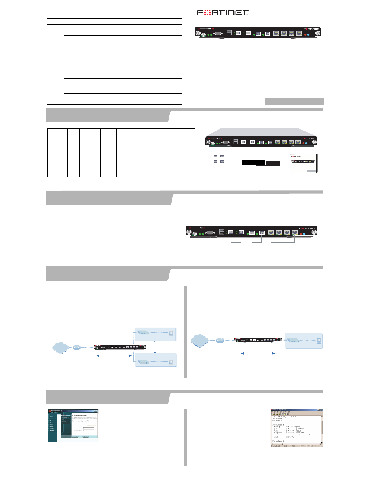
3. To access the FortiGate web-based manager, start Internet Explorer and browse to https://
192.168.1.99 (remember to include the “s” in https://).
4. Type admin in the Name field and select Login.
Web-based manager and
Setup Wizard
Use these tables to record your FortiGate-5001FA2 configuration. You can record NAT/Route or
Transparent mode settings and general settings that apply to both modes.
NAT/Route mode
Using the Setup Wizard
To configure the module using the Setup Wizard, select the Easy
Setup Wizard button and follow the prompts.
Using the web-based manager
To change the administrator password
1. Go to System > Admin > Administrators.
2. Select Change Password for the admin administrator and enter a new password.
To configure interfaces
1. Go to System > Network > Interface.
2. Select the edit icon for each interface to configure.
3. Set the addressing mode for the interface. (see the online help for information.)
•For manual addressing, enter the IP address and netmask for the interface.
•For DHCP addressing, select DHCP and any required settings.
•For PPPoE addressing, select PPPoE, and enter the username and password and
any other required settings.
To configure the Primary and Secondary DNS server IP addresses
1. Go to System > Network > DNS, enter the Primary and Secondary DNS IP
addresses that you recorded above and select Apply.
To configure a Default Gateway
1. Go to Router > Static and select Edit icon for the static route.
2. Set Gateway to the Default Gateway IP address that you recorded above and select
OK.
Transparent mode
To switch from NAT/route mode to transparent mode
1. Go to System > Status, select Change beside Operation Mode, and select OK.
2. Change the IP address of the management computer to 10.10.10.2 and use
Internet Explorer to browse to https://10.10.10.1.
Using the Setup Wizard
To configure the module using the Setup Wizard, select the Easy Setup Wizard button
and follow the prompts.
Using the web-based manager
To change the administrator password using the web-based manager
1. Go to System > Admin > Administrators.
2. Select Change Password for the admin administrator and enter a new password.
To configure the management interface using the web-based manager
1. Go to System > Network > Management.
2. Enter the Management IP address and netmask that you recorded above.
3. Select administrative access options if required and select OK.
To configure the Primary and Secondary DNS server IP addresses
1. Go to System > Network > DNS, enter the Primary and Secondary DNS IP
addresses that you recorded above and select Apply.
To configure a Default Gateway
1. Go to System > Network > Management.
2. Set Default Gateway to the Default Gateway IP address that you recorded above
and select OK.
Select the
Easy Setup Wizard
NAT/Route mode
1. Configure Port 1.
config system interface
edit port1
set mode static
set ip <intf_ip> <netmask_ip>
end
2. Repeat to configure each interface, for example, to configure Port 2:
config system interface
edit port2
set mode static
set ip <intf_ip> <netmask_ip>
end
3. Configure the primary and secondary DNS server IP addresses.
config system dns
set primary <dns-server_ip>
set secondary <dns-server_ip>
end
4. Configure the default gateway.
config router static
edit 1
set gateway <gateway_ip>
end
Transparent mode
1. Change from NAT/Route mode to Transparent mode.
config system global
set opmode transparent
end
2. Wait a moment and then log in again at the prompt.
3. Configure the Management IP address.
config system manageip
set ip <mng_ip> <netmask>
end
Configure the DNS server IP address.
config system dns
set primary <dns-server_ip>
set secondary <dns-server_ip>
end
4. Configure the default route.
config router static
edit 1
set gateway <gateway_ip>
end
Using the
Command Line Interface
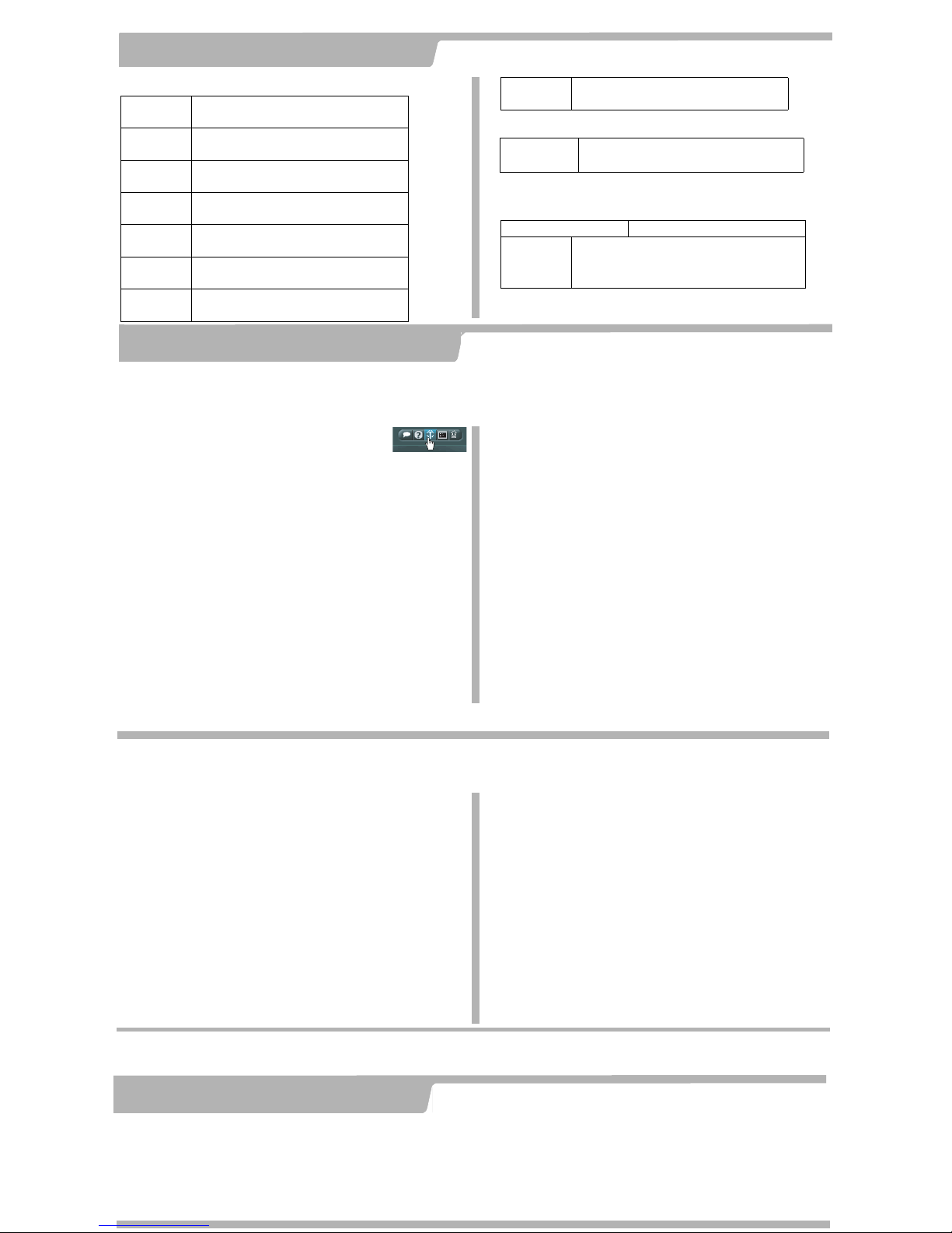
1. Use the serial cable to connect the FortiGate Console port to the management computer serial port.
2. Start a terminal emulation program (HyperTerminal) on the management computer. Use these settings:
Baud Rate (bps) 9600, Data bits 8, Parity None, Stop bits 1, and Flow Control None.
3. At the Login: prompt, type admin and press Enter twice (no password required).
1. Connect Port 1 to the same network as a management computer.
2. Configure the management computer to be on the same subnet as Port 1. To do this,
change the IP address of the management computer to 192.168.1.2 and the netmask to
Note: If you change the IP address of Port 1 (NAT/Route mode) or management IP address (Transparent mode), you must use this address to reconnect to the web-based manager and Setup Wizard. You
might also have to change the IP address of the management computer to be on the same subnet as the new IP address.
Collecting information
5
Configuring the FortiGate-5001FA2
6
Congratulations! You have configured the basic settings. Your network is now protected from
Internet-based threats. To explore the full range of configuration options, see the Documentation.
Completing the configuration
7
• To restart the unit, go to System > Maintenance >
ShutDown and select Reboot.
• To reset the unit, go to System > Maintenance >
Shutdown and select Reset to factory default.
CLI:
execute reboot
Restarting the FortiGate-5001FA2
Should you mistakenly change a network setting and cannot connect to the unit, reboot
the unit and try again or to set the unit back to factory defaults and start over again.
CLI:
execute factoryreset
Technical Documentation
The most up-to-date publications and previous releases of Fortinet product
documentation are available from the Fortinet Technical Documentation web
site at http://docs.forticare.com.
Fortinet Knowledge Center
The knowledge center contains short how-to articles, FAQs, technical notes, product
and feature guides, and much more. Visit the Fortinet Knowledge Center at
http://kc.forticare.com.
Technical Support
Fortinet Technical Support provides services designed to make sure that your
Fortinet systems install quickly, configure easily, and operate reliably in your
network.
Please visit the Fortinet Technical Support web site at http://
support.fortinet.com to learn about the technical support services that Fortinet
provides.
 Loading...