

Fortinet FortiGate FortiGate-5000, FortiGate-5140, FortiGate-5050, FortiGate-5020 Backplane Communications Manual
Page 1

Backplane Communications Guide
FortiGate-5000 Series
Version 3.0 MR5
www.fortinet.com
Page 2

FortiGate-5000 Series Backplane Communications Guide
29 August 2007
01-30005-0423-20070829
© Copyright 2007 Fortinet, Inc. All rights reserved. No part of this
publication including text, examples, diagrams or illustrations may be
reproduced, transmitted, or translated in any form or by any means,
electronic, mechanical, manual, optical or otherwise, for any purpose,
without prior written permission of Fortinet, Inc.
Trademarks
Dynamic Threat Prevention System (DTPS), APSecure, FortiASIC,
FortiBIOS, FortiBridge, FortiClient, FortiGate, FortiGate Unified Threat
Management System, FortiGuard, FortiGuard-Antispam, FortiGuardAntivirus, FortiGuard-Intrusion, FortiGuard-Web, FortiLog, FortiAnalyzer,
FortiManager, Fortinet, FortiOS, FortiPartner, FortiProtect, FortiReporter,
FortiResponse, FortiShield, FortiVoIP, and FortiWiFi are trademarks of
Fortinet, Inc. in the United States and/or other countries. The names of
actual companies and products mentione d herein may be the trade marks
of their respective owners.
Page 3

Contents
Contents
Introduction........................................................................ 5
Warnings and cautions..................................................................................... 5
About this document......................................................................................... 7
Fortinet documentation..................................................................................... 7
Fortinet Tools and Documentation CD.......................................................... 7
Fortinet Knowledge Center ........................................................................... 7
Comments on Fortinet technical documentation........................................... 7
Customer service and technical support........................................................ 7
FortiGate-5140 base backplane communication ............ 9
HA configurations.......................... .... ................................................ ... ........... 10
Two FortiSwitch modules per chassis......................................................... 11
One FortiSwitch module per chassis........................................................... 15
Network configurations................................................................................... 21
Connecting FortiGate modules to each other ............................................. 22
Connecting FortiGate modules to the network............................................ 22
FortiGate-5050 base backplane communication .......... 23
HA configurations.......................... .... ................................................ ... ........... 24
Two FortiSwitch modules per chassis......................................................... 25
One FortiSwitch module per chassis........................................................... 29
Network configurations................................................................................... 35
Connecting FortiGate modules to each other ............................................. 36
Connecting FortiGate modules to the network............................................ 36
FortiGate-5020 base backplane communication .......... 37
HA configurations.......................... .... ................................................ ... ........... 37
Heartbeat failover between channels.......................................................... 38
Inter-chassis HA configurations .................................................................... 41
Network configurations................................................................................... 43
Index.................................................................................. 45
FortiGate-5000 Series Version 3.0 MR5 Backplane Communications Guide
01-30005-0423-20070829 3
Page 4

Contents
FortiGate-5000 Series Version 3.0 MR5 Backplane Communications Guide
4 01-30005-0423-20070829
Page 5

Introduction Warnings and cautions
Introduction
This FortiGate-5000 Series Backplane Communications Guide contains
information, instructions and example configurations involving the base backplane
network interfaces of FortiGate-5000 series systems.
FortiGate-5140, FortiGate-5050 and FortiGate-5020 chassis base backplanes
can provide a communications medium between blade modules. FortiGate-5140
and FortiGate-5050 chassis base backplanes can also p rovide a communication s
medium to other chassis’ base backplanes, or to the network. Supported base
backplane use varies by configuration and by chassis and module types, but can
include:
• high availability (HA) cluster connection
• multi-channel HA cluster connection failover
• inter-chassis HA cluster connection
• multi-channel inter-chassis HA cluster connection failover
• network connection between modules
• inter-chassis network connection between modules
• network connection to the Internet or other network
For specific instructions and examples of your model’s supported features, see
the chapter for your chassis model.
Note: This guide assumes basic familiarity with FortiGate-5000 series hardware. For
hardware and other available documentation, see “Fortinet documentation” on page7.
This guide does not discuss fabric backplane communications, or configurations
involving FortiController. For information on FortiController, see the
FortiController-5208 System Guide.
This section includes the following topics:
• Warnings and cautions
• About this document
• Fortinet documentation
• Customer service and technical support
Warnings and cautions
Only trained and qualified personnel should be allowed to install or maintain
FortiGate-5000 series equipment. Read and comply with all warnings, cautions
and notices in this document.
Caution: You should be aware of the following cautions and warnings before installing
!
FortiGate-5000 series hardware.
FortiGate-5000 Series Version 3.0 MR5 Backplane Communications Guide
01-30005-0423-20070829 5
Page 6

Warnings and cautions Introduction
• Turning off all power switches may not turn off all power to the FortiGate
equipment. Except where noted, disconnect the FortiGate equipment from all
power sources, telecommunications links and networks before installing, or
removing FortiGate components, or perfo rm in g ot he r ma in te na nc e tasks.
Failure to do this can result in personal injury or equipment damage. Some
circuitry in the FortiGate equipment may continue to operate even though all
power switches are off.
• An easily accessible disconnect device, such as a circuit breaker, should be
incorporated into the data center wiring that connects power to the FortiGate
equipment.
• Install FortiGate chassis at the lower positions of a rack to avoid making the
rack top-heavy and unstable.
• Do not insert metal objects or tools into open chassis slots.
• Electrostatic discharge (ESD) can damage FortiGate equipme nt. Only perform
the procedures described in this document from an ESD workstation. If no
such station is available, you can provide some ESD protection by wearing an
anti-static wrist or ankle strap and attaching it to an ESD connector or to a
metal part of a FortiGate chassis.
• Some FortiGate components may overload your supply circuit and imp act your
overcurrent protection and supply wiring. Refer to nameplate ratings to
address this concern.
• Make sure all FortiGate components have reliable grounding. Fortinet
recommends direct connections to the branch circuit.
• If you install a FortiGate component in a closed or multi-unit rack assembly, the
operating ambient temperature of the rack environment may be greater than
room ambient. Make sure the operating ambient temperatur e does not exceed
the manufacturer's maximum rated ambient temperature.
• Installing FortiGate equipment in a rack should be such that the amount of
airflow required for safe operation of the equipment is not compromised.
• This equipment is for installation only in a Restricted Access Location
(dedicated equipment room, service closet or the like), in accordance with the
National Electrical Code.
• Per the National Electrical Code, sizing of a Listed circuit breaker or branch
circuit fuse and the supply conductors to the equipment is based on the
marked input current rating. A product with a marked input current rating of
25 A is required to be placed on a 40 A branch circuit. The supply conductors
will also be sized according to the input current rating and also derated for the
maximum rated operating ambient tem pera tu r e, T ma , of th e eq uip m en t.
• FortiGate equipment shall be installed and connected to an electrical supply
source in accordance with the applicable codes and regulations fo r the location
in which it is installed. Particular attention shall be paid to use of correct wire
type and size to comply with the applicable codes and regulations for the
installation / location. Connection of the supply wiring to the terminal block on
the equipment may be accomplished using Listed wire compression lugs, for
example, Pressure Terminal Connector made by Ideal Industries Inc. or
equivalent which is suitable for AWG 10. Particular attention shall be given to
use of the appropriate compression tool specified by the compression lug
manufacturer, if one is specified.
FortiGate-5000 Series Version 3.0 MR5 Backplane Communications Guide
6 01-30005-0423-20070829
Page 7

Introduction About this document
About this document
This document includes the following chapters:
• FortiGate-5140 base backplane communication describes supported
configurations and features for FortiGate-5140 chassis backplane
communications.
• FortiGate-5050 base backplane communication describes supported
configurations and features for FortiGate-5050 chassis backplane
communications.
• FortiGate-5020 base backplane communication describes supported
configurations and features for FortiGate-5020 chassis backplane
communications.
Fortinet documentation
The most up-to-date publications and previous releases of Fortinet product
documentation are available from the Fortinet Technical Documentation web site
at http://docs.forticare.com. All FortiGate-5000 information is available from the
FortiGate-5000 page.
Fortinet Tools and Documentation CD
All Fortinet documentation is available from th e Fortinet Tools and Documentation
CD shipped with your Fortinet product. The documents on this CD are current at
shipping time. For up-to-date versions of Fortinet documentation see the Fortinet
Technical Doc um entation we b site at http://docs.forticare.com.
Fortinet Knowledge Center
Additional Fortinet technical documentation is available from the Fortinet
Knowledge Center. The knowledge center contains troubleshooting and how-to
articles, FAQs, technical notes, and more. Visit the Fortinet Knowledge Center at
http://kc.forticare.com.
The FortiGate Log Message Reference is available exclusively from the Fortinet
Knowledge Center , the FortiGate Log Messag e Reference describes the structure
of FortiGate log messages and provides information about the log messages that
are generated by FortiGate units.
Comments on Fortinet technical documentation
Please send information about any errors or omissions in this document, or any
Fortinet technical documentation, to techdoc@fortinet.com.
Customer service and technical support
Fortinet Technical Support provides services designed to make sure that your
Fortinet systems install quickly, configure easily, and operate reliably in your
network.
Please visit the Fortinet Technical Support web site at http://support.fortinet.com
to learn about the technical support services that Fortinet provides.
FortiGate-5000 Series Version 3.0 MR5 Backplane Communications Guide
01-30005-0423-20070829 7
Page 8

Customer service and technical support Introduction
FortiGate-5000 Series Version 3.0 MR5 Backplane Communications Guide
8 01-30005-0423-20070829
Page 9
FortiGate-5140 base backplane communication
FortiGate-5140 base backplane
communication
Both the FortiGate-5140 and the FortiGate-5050 chassis have two base
backplane Ethernet channels. Available connections to these channels vary by
slot number.
• Slot 1 can connect to the chassis’ first base backplane channel, and thereby all
other slots, except slot 2.
• Slot 2 can connect the to the chassis’ second base backplane channel, and
thereby all other slots, except slot 1.
• Other slots can connect to either or both channels, but only directly reach
slot 1 or slot 2. Connections to other slots through the base backplane
channels must pass through slot 1 or slot 2.
Note: For more information on chassis architecture, see ATCA (Advanced Telecom
Computing Architecture) specifications.
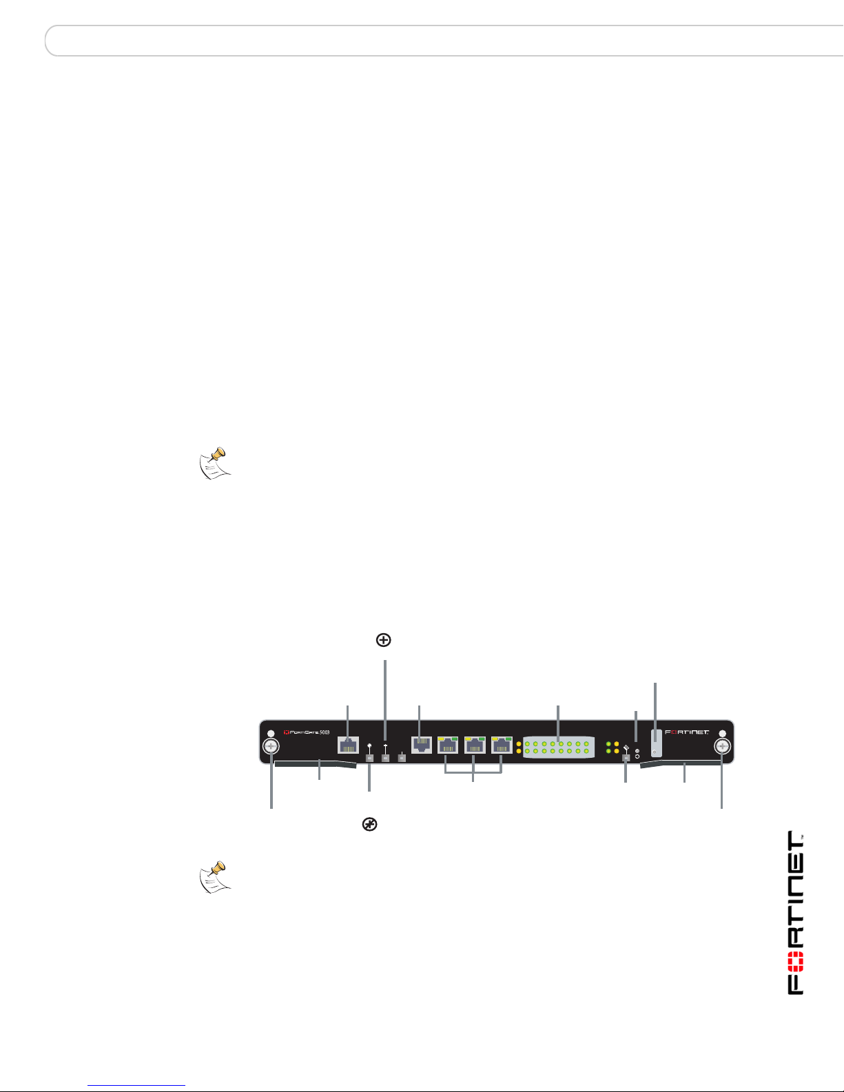
Because of the base backplane’s dual star topology, connecting to or through the
base backplane typically involves FortiSwitch modules installed in slot 1, slot 2, or
both slots. FortiSwitch-5003 modules switch base backplane traffic between
modules in other slots. FortiSwitch-5003 front panel ZRE interfaces can also
connect the chassis’ base backplane to external entities, such as a management
computer, the network, or the base backplane of another chassis.
Figure 1: FortiSwitch-5003 front panel, including ZRE interfaces
Power LED
LED Mode Switch
Reset
Switch
OKCLK
INTEXT
FLT
HOT SWAP
FLT
Hot
Swap
RESET
LED MODE
Extraction
ZRE
LED
Lever
Mounting
Knot
Mounting
Knot
Management
100Base-TX
Ethernet
MANAGEMENT
Extraction
Lever
Service LED
ETH
O
Out of
CONSOLE
RJ-45
Serial
RS232ZRE0ZRE1ZRE2
SYSTEM
CONSOLE
ZRE0 ZRE1 ZRE2
base backplane interfaces
10/100/1000Base-T
Ethernet
ZRE Network
Activity LEDs
(ZRE 0 to 15)
E1
9876543210
1514
1312
1110
E0
Note: FortiSwitch-5003 modules do not support VLAN tagging, so VLAN traffic cannot
occur through the FortiGate-5050 and FortiGate-5140 chassis base backplanes.
When viewing a FortiGate module’s web-based manager, names of base
backplane interfaces connecting through a FortiSwitch module vary by FortiGate
model.
FortiGate-5000 Series Version 3.0 MR5 Backplane Communications Guide
01-30005-0423-20070829 9
Page 10

HA configurations FortiGate-5140 base backplane communication
Table 1: Names of base backplane interfaces by FortiGate model
Model Name of base backplane
FortiGate-5001SX port9 port10
FortiGate-5001FA2 port9 port10
FortiGate-5005FA2 base1 base2
This section contains example HA and network configurations for each hardware
combination. It also discusses how to choose an appropriate amount and slot
number of FortiSwitch modules for base backplane HA.
This section includes the following topics:
• HA configurations
• Network configurations
HA configurations
Valid HA hardware configurations can be formed from FortiGate modules located
in either the same or multiple FortiGate-5050 or FortiGate-5140 chassis, with
either one or two FortiSwitch modules per chassis.
Inter-chassis HA configuration requirements are identical to HA configuration
within the same chassis, except for these additional requirements.
• Link multiple chassis’ base backplanes by connecting ZRE interfaces of
• If each chassis contains only one FortiSwitch module, install each FortiSwitch
It makes no difference whether you use the ZRE0, ZRE1, or ZRE2 interface to link
the base backplanes. You can connect an Ethernet cable, either straight-through
or crossover , from an y of these inter faces on on e FortiSwitch-50 03 module to any
of these interfaces on another FortiSwitch-5003 module installed in the other
chassis. You can also use the ZRE interfaces to connect more than two chassis
together.
Name of base backplane
interface 1 (to slot 1)
interface 2 (to slot 2)
FortiSwitch modules which have the same slot number.
module in matching slot numbers. For example, you coul d link HA m embers in
separate FortiGate-5140 and FortiGate-5050 chassis. If one chassis has only
one FortiSwitch module installed in slot 2, the other chassis’ FortiSwitch
module must also be installed in slot 2. For details, see “Choosing the slot
position” on page 20.
If you do not install each chassis’ FortiSwitch module in matching slot
numbers, instead of forming a single cluster, this forms multiple clusters, some
using port9 (or base1) for HA heartbeat comm u nic ation, and some using
port10 (or base2).
The model of connected chassis does not necessarily have to be the same.
Because the base backplane architectures of the FortiGate-5050 and
FortiGate-5140 chassis are the same, and because their base backplanes can be
connected through FortiSwitch modules, you can connect FortiGate-5 140 and
FortiGate-5050 chassis together and form clusters between these different model
chassis.
FortiGate-5000 Series Version 3.0 MR5 Backplane Communications Guide
10 01-30005-0423-20070829
Page 11
FortiGate-5140 base backplane communication HA configurations
Default heartbeat interfaces vary by the model of the FortiGate modules, and are
not always base backplane interfaces. For example, FortiGate-5005FA2 modules
use fabric1 and fabric2, the fabric backplane rather than the base backplane, as
the default heartbeat interfaces. If this is the case, to send heartbeat
communications through the base backplane, you must enable and adjust the
priority of the base backplane interfaces.
Two FortiSwitch modules per chassis
Installing two FortiSwitch-5003 modules provides two base backplane HA
heartbeat and synchronization channels, and two configuration options:
• Configure heartbeat interface failover to maintain communications thro ugh the
base backplane. For example, if you have FortiGate-5001SX clusters, you
could configure clusters to use port10 as the primary heartbeat interface, and
port9 as a backup if port10 fails or is disconnected, such as could occur if a
FortiSwitch module fails or is removed.
• Separate multiple sensitive or high volume communications, such as HA
communications for multiple clusters. For example, if you have two busy
FortiGate-5001SX clusters, you might configure one cluster to use port9 for
HA heartbeat traffic and the other to use port10.
Required steps vary by which way you want to use the two channels.
Note: More than one cluster can use the same base backplane channel for HA
communication. To separate HA communications of multiple clusters using the same
channel, configure a different HA Group Name and Password for each cluster.
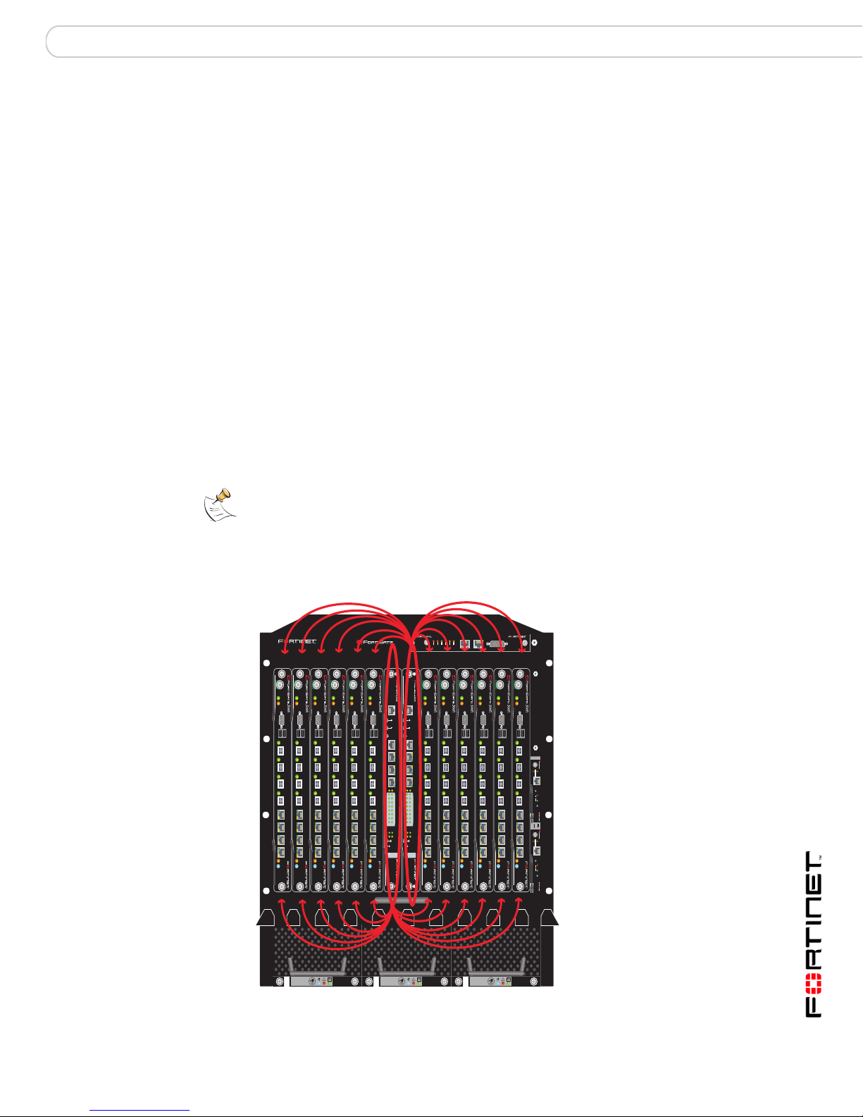
Figure 2: HA cluster with two available base backplane heartbeat interfaces
(through FortiSwitch-5003 modules in slot 1 and slot 2)
base backplane channel 2
5140SAP
5140
1311975312468101214
PWR
PWR
PWR
PWR
PWR
ACC
ACC
ACC
CONSOLE
CONSOLE
CONSOLE
USB
USB
USB
1 2 3 4 5 6 7 8
1 2 3 4 5 6 7 8
1 2 3 4 5 6 7 8
STA IPM
STA IPM
STA IPM
PWR
ACC
ACC
ACC
MANAGEMENT
MANAGEMENT
E
E
T
T
H
H
O
CONSOLE
USB
1 2 3 4 5 6 7 8
STA IPM
STA IPM
O
CONSOLE
CONSOLE
USB
USB
SYSTEM
SYSTEM
CONSOLE
CONSOLE
R
R
S
S
2
2
3
3
2
2
1 2 3 4 5 6 7 8
1 2 3 4 5 6 7 8
Z
Z
R
R
E
E
0
0
Z
Z
R
R
E
E
1
1
Z
Z
R
R
E
E
2
2
E1
E1
E0
E0
1514
1514
1312
1312
1110
1110
98
98
76
76
54
54
32
32
10
10
ZRE
ZRE
OKCLK
OKCLK
INTEXT
INTEXT
FLT
FLT
FLT
FLT
HOT SWAP
HOT SWAP
RESET
RESET
LED MODE
LED MODE
STA IPM
FILTER
SERIAL 1 SERIAL 2 ALARM
USER2
USER1
USER3
MINOR
MAJOR
CRITICAL
RESET
PWR
PWR
PWR
PWR
PWR
ACC
ACC
ACC
CONSOLE
CONSOLE
CONSOLE
USB
USB
USB
1 2 3 4 5 6 7 8
1 2 3 4 5 6 7 8
1 2 3 4 5 6 7 8
PWR
ACC
ACC
ACC
CONSOLE
CONSOLE
CONSOLE
USB
USB
USB
1 2 3 4 5 6 7 8
1 2 3 4 5 6 7 8
1 2 3 4 5 6 7 8
5000SM
ETH1
ETH0
10/100
10/100
link/Act
link/Act
ETH0
Service
RESET
STATUS
Hot Swap
12
5000SM
ETH1
ETH0
10/100
10/100
link/Act
link/Act
ETH0
STA IPM
STA IPM
STA IPM
STA IPM
Service
STA IPM
STA IPM
RESET
STATUS
Hot Swap
0
base backplane channel 1
FortiGate-5000 Series Version 3.0 MR5 Backplane Communications Guide
01-30005-0423-20070829 11
FAN TRAY FAN TRAYFAN TRAY
12
Page 12
HA configurations FortiGate-5140 base backplane communication
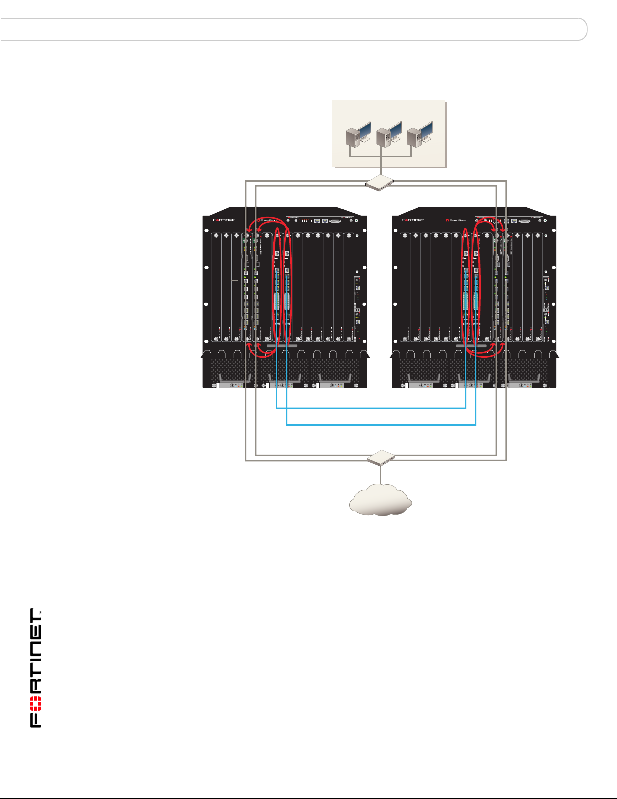
Figure 3: Inter-chassis HA cluster with two available base backplane heartbeat
interfaces (through FortiSwitch-5003 modules in slot 1 and slot 2)
Internal Network
internal network
switch
5140SAP
1311975312468101214
5140
PWR
PWR
ACC
ACC
MANAGEMENT
MANAGEMENT
E
T
H
O
CONSOLE
CONSOLE
USB
USB
SYSTEM
CONSOLE
R
S
2
3
2
1 2 3 4 5 6 7 8
1 2 3 4 5 6 7 8
Z
R
E
0
Z
R
E
1
Z
R
E
2
E0
E0
E1
1514
1312
1110
98
76
54
32
10
ZRE
OKCLK
INTEXT
FLT
FLT
FLT
HOT SWAP
RESET
LED MODE
STA IPM
LED MODE
STA IPM
SERIAL 1 SERIAL 2 ALARM
L
2
1
3
A
R
R
R
OR
C
T
OR
I
E
E
E
E
N
T
I
I
S
S
AJ
S
R
U
US
U
M
M
C
RE
E
T
H
O
SYSTEM
CONSOLE
R
S
2
3
2
Z
R
E
0
Z
R
E
1
Z
R
E
2
E1
1514
1312
1110
98
76
54
32
10
ZRE
OKCLK
INTEXT
FLT
HOT SWAP
RESET
FILTER
0
FAN TRAY FAN TRAYFAN TRAY
12
slot 1 inter-chassis heartbeat
slot 2 inter-chassis heartbeat
Internet
5000SM
ETH1
ETH0
10/100
10/100
link/Act
link/Act
ETH0
Service
RESET
STATUS
Hot Swap
12
5000SM
ETH0ETH1
10/100
10/100
link/Act
link/Act
ETH0
Service
RESET
STATUS
Hot Swap
Internet
5140SAP
1311975312468101214
5140
MANAGEMENT
MANAGEMENT
E
T
H
O
SYSTEM
CONSOLE
R
S
2
3
2
Z
R
E
0
Z
R
E
1
Z
R
E
2
OKCLK
INTEXT
FLT
FLT
FLT
HOT SWAP
RESET
LED MODE
LED MODE
SERIAL 1 SERIAL 2 ALARM
L
2
1
3
R
A
R
R
R
R
O
C
T
O
I
E
E
E
E
N
T
I
I
S
S
S
AJ
S
R
U
U
U
M
M
C
RE
PWR
PWR
ACC
ACC
E
T
H
O
CONSOLE
CONSOLE
USB
SYSTEM
CONSOLE
R
S
2
3
2
OKCLK
INTEXT
FLT
HOT SWAP
RESET
USB
1 2 3 4 5 678
1 2 3 4 5 6 7 8
FILTER
0
FAN TRAY FAN TRAYFAN TRAY
12
switch
5000SM
ETH1
ETH0
10/100
10/100
link/Act
link/Act
ETH0
Service
RESET
STATUS
Hot Swap
12
5000SM
ETH0ETH1
10/100
10/100
link/Act
link/Act
ETH0
Service
RESET
STATUS
Hot Swap
Separating HA clusters by channel
Configuring HA clusters to use separate channe ls essentially causes each cluster
to behave as if it has only one available FortiSwitch module. For instructions on
configuring each cluster to use a separate base backplane interface, see “One
FortiSwitch module per chassis” on page 15.
Heartbeat failover between channels
To configure your HA cluster with a heartbeat that fails over between the two base
backplane interfaces, both base backpla ne interf ace s must be enabled and:
• if priorities are not equal, must have the highest priorities of all heartbeat
interfaces
• if priorities are equal, be the first interfaces on the inde xe d Hear tb eat In te rface
list
FortiGate-5000 Series Version 3.0 MR5 Backplane Communications Guide
12 01-30005-0423-20070829
Page 13
FortiGate-5140 base backplane communication HA configurations
If you also want to specify which FortiSwitch module is used as the primary or
failover, its priority must be greater than the failover interface, or it must have a
higher position in the Heartbeat Interface list. Position in the Heartbeat Interface
list varies by the model of the FortiGate modules.
You can satisfy these requirements in multiple ways by adjusting interface priority
or by disabling heartbeats over oth er interfaces. Required step s vary by the model
of your FortiGate modules, and the number and He artbeat Interface list position of
other interfaces enabled as HA heartbeat interfaces.
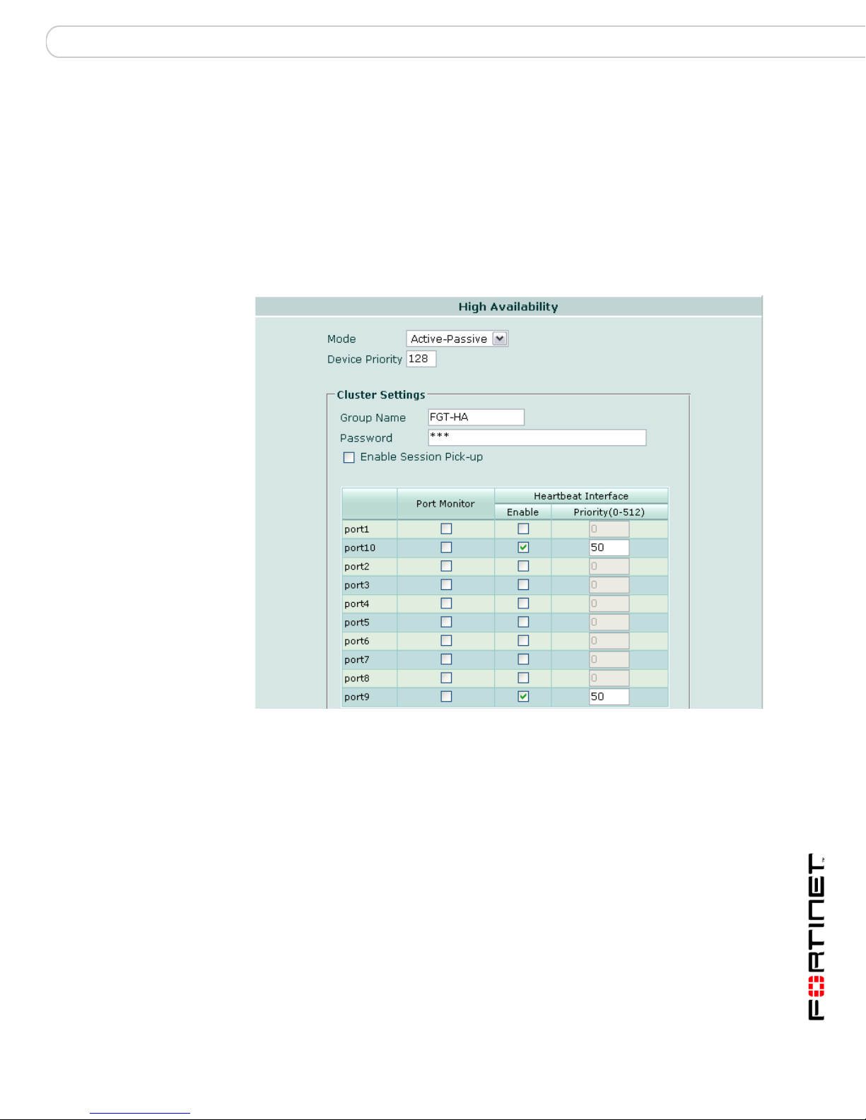
Figure 4: FortiGate-5001SX/FortiGate-5001FA2 heartbeat failover from slot 2
(port10) to slot 1 (port9)
FortiGate-5000 Series Version 3.0 MR5 Backplane Communications Guide
01-30005-0423-20070829 13
Page 14

HA configurations FortiGate-5140 base backplane communication
Figure 5: FortiGate-5005FA2 heartbeat failover from slot 1 (base1) to slot 2 (base2)
To configure HA interface failover to use two FortiSwitch modules
1 Insert FortiSwitch modules into slot 1 and slot 2 of each chassis.
If you want to form HA clusters between FortiGate modules in separate chassis,
link the base backplanes of each chassis by connecting FortiSwitch modules’ front
panel ZRE interfaces with an Ethernet cable.
For example hardware installations, see Figure 2 on page 11 and Figure 3 on
page 12. For details on hardware installation and related warnings and cautions,
see the FortiGate-5000 Series Introduction.
2 Insert FortiGate modules into any remaining chassis slot.
3 Power on each chassis.
4 On each FortiGate module to be included in the HA cluster, go to System >
Config > HA.
5 Select the Mode, then enter the Group Name, and Password.
You may also want to set other options, such as the Device Priority or session
pick-up. For detailed instructions, see the FortiGate HA Guide.
6 If the base backplane interfaces do not have heartbeat interface precedence,
increase the precedence of the base backplane interfaces so that they are
selected as the primary and first failover heartbeat interface.
FortiGate-5000 Series Version 3.0 MR5 Backplane Communications Guide
14 01-30005-0423-20070829
Page 15
FortiGate-5140 base backplane communication HA configurations
Note: Heartbeat interface precedence can be determined by multiple factors, including
Priority and position in the Heartbeat Interface list. For details, see “Slot position and HA
heartbeat interface precedence” on page 20.
• If interface priorities are not all equal, set the base backplane interfaces’
priority to a higher value than all other interfaces.
• If interface priorities are all equal, set the ba se backp lane inte rfaces’ pr iority to
a higher value than all other interfaces, or disable interfaces listed above the
base backplane interfaces in the Heartbeat Interface list. For some FortiGate
models, FortiSwitch slot positions, or configurations of other HA interfaces, this
may mean that no change is required. The table below describes where
changes are required, and if so, what kind.
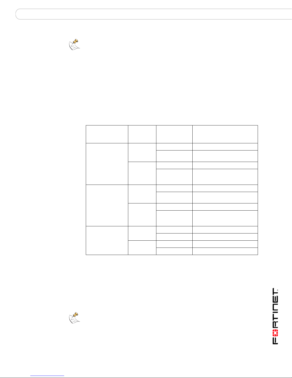
T able 2: Changes to configure base backplane HA, assuming initially equal interface
priorities
Model FortiSwitch
slot
FortiGate-5001SX 1 No
2No
FortiGate-5001FA2 1 No
2No
FortiGate-5005FA2 1 No
2No
Other HA
interfaces
enabled?
Yes Increase priority of port9, or
Yes If port1 is an HA interface,
Yes Increase priority of port9, or
Yes If port1 is an HA interface,
Yes
Yes
HA interface config change
disable other HA interfaces.
increase priority of port10 or
disable port1.
disable other HA interfaces.
increase priority of port10 or
disable port1.
7 If you want to select a different base back plane inte rface as the prima ry heartbeat
interface, increase its priority.
8 Select OK.
One FortiSwitch module per chassis
Installing a single FortiSwitch-5003 module provides a single base backplane HA
heartbeat and synchronization channel.
Note: More than one cluster can use the same base backplane channel for HA
communication. To separate HA communications of multiple clusters using the same
channel, configure a different HA Group Name and Password for each cluster.
FortiGate-5000 Series Version 3.0 MR5 Backplane Communications Guide
01-30005-0423-20070829 15
Page 16

HA configurations FortiGate-5140 base backplane communication
Unlike hardware configurations involving two FortiSwitch modules per chassis,
when installing only one FortiSwitch module per chassis, the slot position of the
FortiSwitch module becomes an important consid eration. Single FortiSwitch-5003
modules should usually be installed in slot 2 for FortiGate-5001SX and
FortiGate-5001F A2 clusters, but slot 1 for FortiGate-50 05FA2 clusters. For details
on the effects of slot positioning of a single FortiSwitch module in HA
configurations, see “Slot position and HA heartbeat interface precedence” on
page 20
Note: Using a single FortiSwitch-5003 module for HA heartbeat communication introduces
a single point of failure. If this FortiSwitch-5003 module fails or is removed, HA heartbeat
communication will be interrupted. For enhanced reliability, you can add a second
FortiSwitch-5003 module. You can also improve reliability by connecting and configuring
one or more other heartbeat interfaces.
Figure 6: HA cluster with one available base backplane heartbeat interface (through
.
FortiSwitch-5003 module in slot 2)
base backplane channel 2
5140SAP
5140
RESET
1311975312468101214
SERIAL 1 SERIAL 2 ALARM
USER2
USER1
USER3
MINOR
MAJOR
CRITICAL
PWR
PWR
PWR
PWR
PWR
ACC
ACC
ACC
ACC
CONSOLE
CONSOLE
CONSOLE
USB
USB
USB
1 2 3 4 5 6 7 8
1 2 3 4 5 6 7 8
1 2 3 4 5 6 7 8
STA IPM
STA IPM
STA IPM
STA IPM
PWR
ACC
ACC
CONSOLE
CONSOLE
CONSOLE
USB
USB
USB
1 2 3 4 5 6 7 8
1 2 3 4 5 6 7 8
1 2 3 4 5 6 7 8
STA IPM
STA IPM
MANAGEMENT
E0
FLT
PWR
PWR
PWR
PWR
PWR
ACC
ACC
ACC
E
T
H
O
CONSOLE
USB
SYSTEM
CONSOLE
R
S
2
3
2
1 2 3 4 5 6 7 8
Z
R
E
0
Z
R
E
1
Z
R
E
2
E1
1514
1312
1110
98
76
54
32
10
ZRE
OKCLK
INTEXT
FLT
HOT SWAP
RESET
LED MODE
STA IPM
STA IPM
ACC
CONSOLE
CONSOLE
USB
USB
1 2 3 4 5 6 7 8
1 2 3 4 5 6 7 8
STA IPM
STA IPM
PWR
ACC
ACC
CONSOLE
CONSOLE
CONSOLE
USB
USB
USB
1 2 3 4 5 6 7 8
1 2 3 4 5 6 7 8
1 2 3 4 5 6 7 8
5000SM
ETH1
ETH0
10/100
10/100
link/Act
link/Act
ETH0
Service
RESET
STATUS
Hot Swap
12
5000SM
ETH1
ETH0
10/100
10/100
link/Act
link/Act
ETH0
STA IPM
Service
STA IPM
RESET
STATUS
Hot Swap
FILTER
0
FAN TR AY FAN TR AYFAN TR AY
12
To configure your HA cluster to use the base backplane interface connected
through a single FortiSwitch, the base backplane interface must be enabled as a
heartbeat interface and:
• if priorities are not equal, have the highest priority of all heartbeat interfaces
FortiGate-5000 Series Version 3.0 MR5 Backplane Communications Guide
16 01-30005-0423-20070829
Page 17

FortiGate-5140 base backplane communication HA configurations
• if priorities are equal, be the first interface on the indexed Heartbeat Interface
list
You can satisfy these requirements in multiple ways by adjusting interface priority
or by disabling heartbeats over other interfaces. Required steps vary by the slot
position of the FortiSwitch module, the model of your FortiGate modules, and the
number and Heartbeat Interface list position of other interfaces enabled as
heartbeat interfaces.
Figure 7: FortiGate-5001SX/FortiGate-5001FA2 HA through slot 2 (port10) with
failover to a non-base backplane interface
FortiGate-5000 Series Version 3.0 MR5 Backplane Communications Guide
01-30005-0423-20070829 17
Page 18

HA configurations FortiGate-5140 base backplane communication
Figure 8: FortiGate-5005FA2 HA through slot 1 (base1) with failover to a non-base
backplane interface
To configure HA communications to use one FortiSwitch module
1 Insert FortiSwitch modules into slot 1 or slot 2 of each chassis.
When installing only one FortiSwitch module per chassis, recommended slot
number varies by the model of the FortiGate modules. For details on the effects of
slot number, see “Slot position and HA heartbeat interface precedence” on
page 20.
If you want to form HA clusters between FortiGate modules in separate chassis,
install each FortiSwitch module into matching slot numbers in each chassis, then
link the base backplanes of each chassis by connecting FortiSwitch modules’ front
panel ZRE interfaces with an Ethernet cable.
For example hardware installations, see Figure 6 on page 16 and Figur e 3 on
page 12. For details on hardware installation and related warnings and cautions,
see the FortiGate-5000 Series Introduction.
2 Insert FortiGate modules into any remaining chassis slot.
3 Power on each chassis.
4 On each FortiGate module to be included in the HA cluster, go to System >
Config > HA.
FortiGate-5000 Series Version 3.0 MR5 Backplane Communications Guide
18 01-30005-0423-20070829
Page 19

FortiGate-5140 base backplane communication HA configurations
5 Select the Mode, then enter the Group Name, an d Pa sswo rd.
You may also want to set other options, such as the Device Priority or session
pick-up. For detailed instructions, see the FortiGate HA Guide.
6 If the base backplane interface does not have heartbeat interface precedence,
increase the precedence of the base backplane interface so that it is selected as
the primary heartbeat interface.
Note: Heartbeat interface precedence can be determined by multiple factors, including
Priority and position in the Heartbeat Interface list. For details, see “Slot position and HA
heartbeat interface precedence” on page 20.
• If interface priorities are not all equal, set the base backplane interface’s
priority to a higher value than all other interfaces.
• If interface priorities are all equal, set the base backp lane inte rface’ s prior ity to
a higher value than all other interfaces, or disable interfaces listed above the
base backplane interface in the Heartbeat Interface list. For some FortiGate
models, FortiSwitch slot positions, or configurations of other HA interfaces, this
may mean that no change is required. The table below describes where
changes are required, and if so, what kind.
T able 3: Changes to configure base backplane HA, assuming initially equal interface
priorities
Model FortiSwitch
slot
FortiGate-5001SX 1 No
2No
FortiGate-5001FA2 1 No
2No
FortiGate-5005FA2 1 No
2No
Other HA
interfaces
enabled?
Yes Increase priority of port9, or
Yes If port1 is an HA interface,
Yes Increase priority of port9, or
Yes If port1 is an HA interface,
Yes
Yes
HA interface config change
disable other HA interfaces.
increase priority of port10 or
disable port1.
disable other HA interfaces.
increase priority of port10 or
disable port1.
7 Select OK.
FortiGate-5000 Series Version 3.0 MR5 Backplane Communications Guide
01-30005-0423-20070829 19
Page 20

HA configurations FortiGate-5140 base backplane communication
Choosing the slot position
Depending on the types of communications, HA or other, that you want to pass
through your FortiSwitch modules, you may choose to install FortiSwitch-5003
modules in different slots: slot 1, slot 2, or both. (Other hardware configurations
are possible but often not preferable for various reasons, such as points of failure
or base backplane topology.)
When using FortiSwitch modules to provide a network connection to the base
backplane, slot position does not matter. However, you can improve robustness
by installing FortiSwitch modules in both slots and providing a redundant link.
For all types of communication, using both slots has the advantage of improving
reliability of communications through or to the base backplane because no
FortiSwitch is a single point of failure. Using both slots also provides the option of
separating multip le sensitive or high volume communications, such as HA
communications for multiple clusters.
Note: For HA configurations, you can further improve fault tolerance by adding one or more
non-base backplane interfaces as heartbeat interface failovers.
However, if you install only one FortiSwitch module, in addition to fault tolerance
considerations, the slot position has additional effects specific to HA.
• Inter-chassis HA configurations require th at th e switc h use the same slot
number in each chassis so that each cluster member’s configuration uses the
same heartbeat interface.
• Slot position affects HA heartbeat interface selection and failover order.
Slot position and HA heartbeat interface precedence
When installing only one FortiSwitch-5003 module with an HA cluster of
FortiGate-5001SX or FortiGate-5001FA2 modules, it is usually preferable to use
slot 2. This allows you to connect one or more of the other FortiGate-5001SX or
FortiGate-5001FA2 interfaces as backup HA heartbeat interfaces.
The preferred FortiSwitch module slot is different for FortiGate-5005FA2 module
HA clusters. In this case, it is usually preferable to use slot 1.
The reason for selecting different slots is related to the mechanism for heartbeat
interface selection, which is indirectly tied to slot number.
During heartbeat interface selection, the heartbeat interface with the highest
priority is selected first. If multiple heartbeat interfaces have highest priority,
including when all have equal priority, the HA cluster chooses a heartbeat
interface using the Heartbeat Interface list.
This list is sorted into hash map order, rather than purely by alphabetical order or
purely by interface number value comparisons. As a result, the list is sorted
primarily alphabetical by interface name (for example, base1 is before port1), then
secondarily by index numbers:
•1
•10
• 2 through 8
•9
FortiGate-5000 Series Version 3.0 MR5 Backplane Communications Guide
20 01-30005-0423-20070829
Page 21

FortiGate-5140 base backplane communication Network configurations
Note: The FortiGate web-based manager and CLI list interfaces in sort order.
Because interface names, and therefore sort order, vary by FortiGate model, the
preferred slot number for single FortiSwitch modules varies by FortiGate model.
For example, a FortiGate-5001SX or FortiGate-5001FA2 module has interfaces
named port1 through port10; port9 and port10 are equally weighted heartbeat
interfaces, connected to the slot 1 FortiSwitch and the slot 2 FortiSwitch,
respectively. In the Heartbeat Interface list, port1 is first. However, port10 is not
last: due to hash map lookup,port10 is selected after port1 and before port2, not
after port9. Failover passes heartbeat communications from the FortiSwitch
module in slot 2 to slot 1.
There are additional considerations if you create additional heartbeat backup
interfaces connecting FortiGate module interfaces port2 through port8. In this
case, if the FortiSwitch module in slot 2 fails or is removed, the FortiGate cluster
could fail over to port2 through port8, and lastly fail over to the interface co nnected
to the FortiSwitch module in slot 1.
Because of this behavior, if you in stall a single FortiSwitch module in slot 1 with
those two models of FortiGate modules, and want to give heartbeat selection
precedence to the base backplane int er fa c e, you must set its heartbeat interface
priority to a greater value than the other interfaces. Otherwise, by default, when
priorities are equal, the heartbeat link through the base backplane interface will be
used only in failover, rather than primary, conditions. This is typically the inverse
of intended behavior.
Network configurations
In addition to HA traffic, FortiSwitch modules can pass other traffic types through
or to the base backplane.
Note: FortiSwitch-5003 modules do not support VLAN-tagged packets, so VLAN traffic
cannot occur through the FortiGate-5050 and FortiGate-5140 chassis base backplanes.
Like HA scenarios, network configurations can involve one or two FortiSwitch
modules per chassis, and one or more chassis.
However, unlike HA scenarios, modules connecting to transfer other traffic types
need not use identical interface numbers on each side of the connection, and
therefore they do not require FortiSwitch modules installed in the same slot
numbers. Because of this, by connecting one of the ZRE interfaces on each slot’ s
FortiSwitch module to another, you can send non-HA traffic between FortiGate
modules that use different base backplane interfaces.
For example, if an HA cluster of FortiGate-5005FA2 modules using base1 (slot 1)
for heartbeat traffic need to send some traffic to a second HA cluster of modules
in the same chassis that use base2 (slot 2) for their heartbeat traffic, you can
connect the two clusters across the two base backplane channels by linking one
of the ZRE interfaces on the slot 1 FortiSwitch module to one of the ZRE
interfaces on the slot 2 FortiSwitch module.
FortiGate-5000 Series Version 3.0 MR5 Backplane Communications Guide
01-30005-0423-20070829 21
Page 22

Network configurations FortiGate-5140 base backplane communication
In addition to linking base backplane traffic between FortiGate modules, you can
use FortiSwitch modules to link traffic between FortiGate modules’ base
backplane interfaces and your network, or the Internet. Connecting a ZRE
interface to the network links the base backplane, and any connected FortiGate
modules, to the network.
Required steps vary by whether you want to use the base backplane interfaces to
connect FortiGate modules to each other, or to the network. These scenarios are
not mutually exclusive; you can simultaneously provide both.
Note: You can also combine network configurations with HA configurations to send both
traffic types through the base backplane channel(s). However, because heavy heartbeat or
network traffic load can interfere with the other traffic type’s performance, it is generally
preferable to separate those traffic types to different base backplane interfaces. This
requires two FortiSwitch modules per chassis.
Connecting FortiGate modules to each other
By installing one or two FortiSwitch modules per chassis, you can connect
FortiGate modules to each other through their base backplane interf aces.
Hardware configurations are identical to single and multiple chassis configurations
for HA traffic, except the additional possibility of connecting FortiSwitch modules
that have been installed in different slot numbers. Connecting FortiSwitch
modules located in different slot numbers allows communication between the two
base backplane channels.
Configure FortiGate modules to communicate through the base backplane
interfaces as you would other interfaces.
Connecting FortiGate modules to the network
By installing one or two FortiSwitch modules per chassis, you can connect
FortiGate modules to the network or Internet through their base backplane
interfaces.
There are several ways you can connect FortiGate modules to the network,
depending on your available hardware and other goals such as hardware
redundancy.
• The most basic way to connect FortiGate modules to the network through the
base backplane is to connect one of the FortiSwitch module’s ZRE interfaces
to the network.
• By installing a second FortiSwitch module per chassis, you can provide a
redundant network or Internet connection.
• By connecting ZRE interfaces of other chassis’ FortiSwitch modules to the
ZRE interface of the FortiSwitch module connected to the network, you can
provide a shared network or Internet connection.
Configure FortiGate modules to communicate with the network through the base
backplane interfaces as you would other interfaces.
FortiGate-5000 Series Version 3.0 MR5 Backplane Communications Guide
22 01-30005-0423-20070829
Page 23

FortiGate-5050 base backplane communication
FortiGate-5050 base backplane
communication
Both the FortiGate-5140 and the FortiGate-5050 chassis have two base
backplane Ethernet channels. Available connections to these channels vary by
slot number.
• Slot 1 can connect to the chassis’ first base backplane channel, and thereby all
other slots, except slot 2.
• Slot 2 can connect the to the chassis’ second base backplane channel, and
thereby all other slots, except slot 1.
• Other slots can connect to either or both channels, but only directly reach
slot 1 or slot 2. Connections to other slots through the base backplane
channels must pass through slot 1 or slot 2.
Note: For more information on chassis architecture, see ATCA (Advanced Telecom
Computing Architecture) specifications.
Because of the base backplane’s dual star topology, connecting to or through the
base backplane typically involves FortiSwitch modules installed in slot 1, slot 2, or
both slots. FortiSwitch-5003 modules switch base backplane traffic between
modules in other slots. FortiSwitch-5003 front panel ZRE interfaces can also
connect the chassis’ base backplane to external entities, such as a management
computer, the network, or the base backplane of another chassis.
Figure 9: FortiSwitch-5003 front panel, including ZRE interfaces
Power LED
LED Mode Switch
Reset
Switch
OKCLK
INTEXT
FLT
HOT SWAP
FLT
Hot
Swap
RESET
LED MODE
Extraction
ZRE
LED
Lever
Mounting
Knot
Mounting
Knot
Management
100Base-TX
Ethernet
MANAGEMENT
Extraction
Lever
Service LED
ETH
O
Out of
CONSOLE
RJ-45
Serial
RS232ZRE0ZRE1ZRE2
SYSTEM
CONSOLE
ZRE0 ZRE1 ZRE2
base backplane interfaces
10/100/1000Base-T
Ethernet
ZRE Network
Activity LEDs
(ZRE 0 to 15)
E1
9876543210
1514
1312
1110
E0
Note: FortiSwitch-5003 modules do not support VLAN tagging, so VLAN traffic cannot
occur through the FortiGate-5050 and FortiGate-5140 chassis base backplanes.
When viewing a FortiGate module’s web-based manager, names of base
backplane interfaces connecting through a FortiSwitch module vary by FortiGate
model.
FortiGate-5000 Series Version 3.0 MR5 Backplane Communications Guide
01-30005-0423-20070829 23
Page 24

HA configurations FortiGate-5050 base backplane communication
Table 4: Names of base backplane interfaces by FortiGate model
Model Name of base backplane
FortiGate-5001SX port9 port10
FortiGate-5001FA2 port9 port10
FortiGate-5005FA2 base1 base2
This section contains example HA and network configurations for each hardware
combination. It also discusses how to choose an appropriate amount and slot
number of FortiSwitch modules for base backplane HA.
This section includes the following topics:
• HA configurations
• Network configurations
HA configurations
Valid HA hardware configurations can be formed from FortiGate modules located
in either the same or multiple FortiGate-5050 or FortiGate-5140 chassis, with
either one or two FortiSwitch modules per chassis.
Inter-chassis HA configuration requirements are identical to HA configuration
within the same chassis, except for these additional requirements.
• Link multiple chassis’ base backplanes by connecting ZRE interfaces of
• If each chassis contains only one FortiSwitch module, install each FortiSwitch
It makes no difference whether you use the ZRE0, ZRE1, or ZRE2 interface to link
the base backplanes. You can connect an Ethernet cable, either straight-through
or crossover , from an y of these inter faces on on e FortiSwitch-50 03 module to any
of these interfaces on another FortiSwitch-5003 module installed in the other
chassis. You can also use the ZRE interfaces to connect more than two chassis
together.
Name of base backplane
interface 1 (to slot 1)
interface 2 (to slot 2)
FortiSwitch modules which have the same slot number.
module in matching slot numbers. For example, you coul d link HA m embers in
separate FortiGate-5140 and FortiGate-5050 chassis. If one chassis has only
one FortiSwitch module installed in slot 2, the other chassis’ FortiSwitch
module must also be installed in slot 2. For details, see “Choosing the slot
position” on page 34.
If you do not install each chassis’ FortiSwitch module in matching slot
numbers, instead of forming a single cluster, this forms multiple clusters, some
using port9 (or base1) for HA heartbeat comm u nic ation, and some using
port10 (or base2).
The model of connected chassis does not necessarily have to be the same.
Because the base backplane architectures of the FortiGate-5050 and
FortiGate-5140 chassis are the same, and because their base backplanes can be
connected through FortiSwitch modules, you can connect FortiGate-5 140 and
FortiGate-5050 chassis together and form clusters between these different model
chassis.
FortiGate-5000 Series Version 3.0 MR5 Backplane Communications Guide
24 01-30005-0423-20070829
Page 25

FortiGate-5050 base backplane communication HA configurations
Default heartbeat interfaces vary by the model of the FortiGate modules, and are
not always base backplane interfaces. For example, FortiGate-5005FA2 modules
use fabric1 and fabric2, the fabric backplane rather than the base backplane, as
the default heartbeat interfaces. If this is the case, to send heartbeat
communications through the base backplane, you must enable and adjust the
priority of the base backplane interfaces.
Two FortiSwitch modules per chassis
Installing two FortiSwitch-5003 modules provides two base backplane HA
heartbeat and synchronization channels, and two configuration options:
• Configure heartbeat interface failover to maintain communications thro ugh the
base backplane. For example, if you have FortiGate-5001SX clusters, you
could configure clusters to use port10 as the primary heartbeat interface, and
port9 as a backup if port10 fails or is disconnected, such as could occur if a
FortiSwitch module fails or is removed.
• Separate multiple sensitive or high volume communications, such as HA
communications for multiple clusters. For example, if you have two busy
FortiGate-5001SX clusters, you might configure one cluster to use port9 for
HA heartbeat traffic and the other to use port10.
Required steps vary by which way you want to use the two channels.
Note: More than one cluster can use the same base backplane channel for HA
communication. To separate HA communications of multiple clusters using the same
channel, configure a different HA Group Name and Password for each cluster.
Figure 10: HA cluster with two available base backplane heartbeat interfaces
(through FortiSwitch-5003 modules in slot 1 and slot 2)
USB
1 2 3 4 5 6 7 8
base
backplane
channel 2
5
4
3
2
1
5000SM
SMC
2
CONSOLE
ACC
PWR
USB
1 2 3 4 5 6 7 8
CONSOLE
ACC
PWR
USB
1 2 3 4 5 6 7 8
CONSOLE
ACC
PWR
ETH
O
RS232ZRE0ZRE1ZRE2
SYSTEM
CONSOLE
MANAGEMENT
ETH
O
RS232ZRE0ZRE1ZRE2
SYSTEM
CONSOLE
MANAGEMENT
10/100
ETH0
Service
link/Act
ETH1
STATUS
10/100
RESET
ETH0
link/Act
5050SAP
SERIAL
Hot Swap
1
E1
9876543210
1514
1312
1110
E2
E1
9876543210
1514
1312
1110
E2
SERIAL
ALARM
2
STA IPM
STA IPM
STA IPM
OKCLK
INTEXT
FLT
HOT SWAP
RESET
ZRE
LED MODE
FLT
OKCLK
INTEXT
FLT
HOT SWAP
RESET
ZRE
LED MODE
FLT
5000SM
10/100
ETH0
Service
link/Act
ETH1
10/100
ETH0
link/Act
POWER
SMC
STATUS
Hot Swap
RESET
1
base
backplane
channel 1
FortiGate-5000 Series Version 3.0 MR5 Backplane Communications Guide
01-30005-0423-20070829 25
Page 26

HA configurations FortiGate-5050 base backplane communication
Figure 11: Inter-chassis HA cluster with two available base backplane heartbeat
interfaces (through FortiSwitch-5003 modules in slot 1 and slot 2)
Internal Network
internal network
switch
USB
1 2 3 4 5 6 7 8
CONSOLE
ACC
PWR
5
4
3
2
1
5000SM
SMC
2
USB
1 2 3 4 5 6 7 8
CONSOLE
ACC
PWR
ETH
O
RS232ZRE0ZRE1ZRE2
E1
1514
1312
SYSTEM
CONSOLE
MANAGEMENT
ETH
O
RS232ZRE0ZRE1ZRE2
SYSTEM
CONSOLE
MANAGEMENT
10/100
ETH0
link/Act
ETH1
10/100
ETH0
link/Act
5050SAP
Service
SERIAL
STATUS
Hot Swap
RESET
1
1110
E0
E1
1514
1312
1110
E0
ALARM
9876543210
9876543210
STA IPM
5
4
STA IPM
OKCLK
INTEXT
FLT
HOT SWAP
RESET
ZRE
FLT
OKCLK
INTEXT
FLT
HOT SWAP
ZRE
FLT
5000SM
10/100
link/Act
SERIAL
10/100
2
ETH0ETH1
link/Act
POWER
LED MODE
RESET
LED MODE
SMC
ETH0
Service
STATUS
Hot Swap
RESET
1
3
2
1
5000SM
SMC
2
USB
1 2 3 4 5 6 7 8
CONSOLE
ACC
PWR
USB
1 2 3 4 5 6 7 8
CONSOLE
ACC
PWR
ETH
O
RS232ZRE0ZRE1ZRE2
E1
1514
1312
SYSTEM
CONSOLE
MANAGEMENT
ETH
O
RS232ZRE0ZRE1ZRE2
SYSTEM
CONSOLE
MANAGEMENT
10/100
ETH0
link/Act
10/100
ETH0ETH1
link/Act
5050SAP
Service
SERIAL
STATUS
Hot Swap
RESET
1
1110
E0
E1
1514
1312
1110
E0
ALARM
9876543210
9876543210
STA IPM
STA IPM
OKCLK
INTEXT
FLT
HOT SWAP
RESET
ZRE
FLT
OKCLK
INTEXT
FLT
HOT SWAP
ZRE
FLT
5000SM
10/100
link/Act
ETH1
SERIAL
10/100
2
ETH0
link/Act
POWER
LED MODE
RESET
LED MODE
SMC
ETH0
Service
STATUS
Hot Swap
RESET
1
slot 1 inter-chassis heartbeat
slot 2 inter-chassis heartbeat
switch
Internet
Internet
Separating HA clusters by channel
Configuring HA clusters to use separate channe ls essentially causes each cluster
to behave as if it has only one available FortiSwitch module. For instructions on
configuring each cluster to use a separate base backplane interface, see “One
FortiSwitch module per chassis” on page 29.
Heartbeat failover between channels
To configure your HA cluster with a heartbeat that fails over between the two base
backplane interfaces, both base backpla ne interf ace s must be enabled and:
• if priorities are not equal, must have the highest priorities of all heartbeat
interfaces
• if priorities are equal, be the first interfaces on the inde xe d Hear tb eat In te rface
list
If you also want to specify which FortiSwitch module is used as the primary or
failover, its priority must be greater than the failover interface, or it must have a
higher position in the Heartbeat Interface list. Position in the Heartbeat Interface
list varies by the model of the FortiGate modules.
FortiGate-5000 Series Version 3.0 MR5 Backplane Communications Guide
26 01-30005-0423-20070829
Page 27

FortiGate-5050 base backplane communication HA configurations
You can satisfy these requirements in multiple ways by adjusting interface priority
or by disabling heartbeats over oth er interfaces. Required step s vary by the model
of your FortiGate modules, and the number and He artbeat Interface list position of
other interfaces enabled as HA heartbeat interfaces.
Figure 12: FortiGate-5001SX/FortiGate-5001FA2 heartbeat failover from slot 2
(port10) to slot 1 (port9)
FortiGate-5000 Series Version 3.0 MR5 Backplane Communications Guide
01-30005-0423-20070829 27
Page 28

HA configurations FortiGate-5050 base backplane communication
Figure 13: FortiGate-5005FA2 heartbeat failover from slot 1 (base1) to slot 2 (base2)
To configure HA interface failover to use two FortiSwitch modules
1 Insert FortiSwitch modules into slot 1 and slot 2 of each chassis.
If you want to form HA clusters between FortiGate modules in separate chassis,
link the base backplanes of each chassis by connecting FortiSwitch modules’ front
panel ZRE interfaces with an Ethernet cable.
For example hardware installations, see Figure 10 on page 25 and Figu r e 11 on
page 26. For details on hardware installation and related warnings and cautions,
see the FortiGate-5000 Series Introduction.
2 Insert FortiGate modules into any remaining chassis slot.
3 Power on each chassis.
4 Insert FortiGate modules into any remaining chassis slot.
5 Power on each chassis.
6 On each FortiGate module to be included in the HA cluster, go to System >
Config > HA.
7 Select the Mode, then enter the Group Name, and Password.
You may also want to set other options, such as the Device Priority or session
pick-up. For detailed instructions, see the FortiGate HA Guide.
FortiGate-5000 Series Version 3.0 MR5 Backplane Communications Guide
28 01-30005-0423-20070829
Page 29

FortiGate-5050 base backplane communication HA configurations
8 If the base backplane interfaces do not have heartbeat interface precedence,
increase the precedence of the base backplane interfaces so that they are
selected as the primary and first failover heartbeat interface.
Note: Heartbeat interface precedence can be determined by multiple factors, including
Priority and position in the Heartbeat Interface list. For details, see “Slot position and HA
heartbeat interface precedence” on page 34.
• If interface priorities are not all equal, set the base backplane interfaces’
priority to a higher value than all other interfaces.
• If interface priorities are all equal, set the ba se backp lane inte rfaces’ pr iority to
a higher value than all other interfaces, or disable interfaces listed above the
base backplane interfaces in the Heartbeat Interface list. For some FortiGate
models, FortiSwitch slot positions, or configurations of other HA interfaces, this
may mean that no change is required. The table below describes where
changes are required, and if so, what kind.
T able 5: Changes to configure base backplane HA, assuming initially equal interface
priorities
Model FortiSwitch
slot
FortiGate-5001SX 1 No
2No
FortiGate-5001FA2 1 No
2No
FortiGate-5005FA2 1 No
2No
Other HA
interfaces
enabled?
Yes Increase priority of port9, or
Yes If port1 is an HA interface,
Yes Increase priority of port9, or
Yes If port1 is an HA interface,
Yes
Yes
HA interface config change
disable other HA interfaces.
increase priority of port10 or
disable port1.
disable other HA interfaces.
increase priority of port10 or
disable port1.
9 If you want to select a different base back plane inte rface as the prima ry heartbeat
interface, increase its priority.
10 Select OK.
One FortiSwitch module per chassis
Installing a single FortiSwitch-5003 module provides a single base backplane HA
heartbeat and synchronization channel.
FortiGate-5000 Series Version 3.0 MR5 Backplane Communications Guide
01-30005-0423-20070829 29
Page 30

HA configurations FortiGate-5050 base backplane communication
Note: More than one cluster can use the same base backplane channel for HA
communication. To separate HA communications of multiple clusters using the same
channel, configure a different HA Group Name and Password for each cluster.
Unlike hardware configurations involving two FortiSwitch modules per chassis,
when installing only one FortiSwitch module per chassis, the slot position of the
FortiSwitch module becomes an important consid eration. Single FortiSwitch-5003
modules should usually be installed in slot 2 for FortiGate-5001SX and
FortiGate-5001F A2 clusters, but slot 1 for FortiGate-50 05FA2 clusters. For details
on the effects of slot positioning of a single FortiSwitch module in HA
configurations, see “Slot position and HA heartbeat interface precedence” on
page 34
Note: Using a single FortiSwitch-5003 module for HA heartbeat communication introduces
a single point of failure. If this FortiSwitch-5003 module fails or is removed, HA heartbeat
communication will be interrupted. For enhanced reliability, you can add a second
FortiSwitch-5003 module. You can also improve reliability by connecting and configuring
one or more other heartbeat interfaces.
Figure 14: HA cluster with one available base backplane heartbeat interface (through
.
FortiSwitch-5003 module in slot 2)
USB
1 2 3 4 5 6 7 8
USB
1 2 3 4 5 6 7 8
USB
1 2 3 4 5 6 7 8
RS232ZRE0ZRE1ZRE2
SYSTEM
CONSOLE
E1
1514
1312
1110
E2
9876543210
STA IPM
STA IPM
STA IPM
OKCLK
INTEXT
FLT
HOT SWAP
RESET
ZRE
LED MODE
FLT
POWER
base
backplane
channel 2
5
4
3
2
CONSOLE
ACC
PWR
CONSOLE
ACC
PWR
CONSOLE
ACC
PWR
ETH
O
MANAGEMENT
1
5000SM
10/100
SMC
ETH0
Service
link/Act
ETH1
STATUS
10/100
ETH0
link/Act
2
Hot Swap
RESET
5050SAP
SERIAL
1
ALARM
5000SM
10/100
ETH0
Service
link/Act
ETH1
SERIAL
10/100
2
ETH0
link/Act
SMC
STATUS
Hot Swap
RESET
1
To configure your HA cluster to use the base backplane interface connected
through a single FortiSwitch, the base backplane interface must be enabled as a
heartbeat interface and:
• if priorities are not equal, have the highest priority of all heartbeat interfaces
• if priorities are equal, be the first interface on the indexed Heartbeat Interface
list
You can satisfy these requirements in multiple ways by adjusting interface priority
or by disabling heartbeats over other interfaces. Required steps vary by the slot
position of the FortiSwitch module, the model of your FortiGate modules, and the
number and Heartbeat Interface list position of other interfaces enabled as
heartbeat interfaces.
FortiGate-5000 Series Version 3.0 MR5 Backplane Communications Guide
30 01-30005-0423-20070829
Page 31

FortiGate-5050 base backplane communication HA configurations
Figure 15: FortiGate-5001SX/FortiGate-5001FA2 HA through slot 2 (port10) with
failover to a non-base backplane interface
FortiGate-5000 Series Version 3.0 MR5 Backplane Communications Guide
01-30005-0423-20070829 31
Page 32

HA configurations FortiGate-5050 base backplane communication
Figure 16: FortiGate-5005FA2 HA through slot 1 (base1) with failover to a non-base
backplane interface
To configure HA communications to use one FortiSwitch module
1 Insert FortiSwitch modules into slot 1 or slot 2 of each chassis.
When installing only one FortiSwitch module per chassis, recommended slot
number varies by the model of the FortiGate modules. For details on the effects of
slot number, see “Slot position and HA heartbeat interface precedence” on
page 34.
If you want to form HA clusters between FortiGate modules in separate chassis,
install each FortiSwitch module into matching slot numbers in each chassis, then
link the base backplanes of each chassis by connecting FortiSwitch modules’ front
panel ZRE interfaces with an Ethernet cable.
For example hardware installations, see Figure 14 on page 30 and Figu r e 11 on
page 26. For details on hardware installation and related warnings and cautions,
see the FortiGate-5000 Series Introduction.
2 Insert FortiGate modules into any remaining chassis slot.
3 Power on each chassis.
4 On each FortiGate module to be included in the HA cluster, go to System >
Config > HA.
FortiGate-5000 Series Version 3.0 MR5 Backplane Communications Guide
32 01-30005-0423-20070829
Page 33

FortiGate-5050 base backplane communication HA configurations
5 Select the Mode, then enter the Group Name, an d Pa sswo rd.
You may also want to set other options, such as the Device Priority or session
pick-up. For detailed instructions, see the FortiGate HA Guide.
6 If the base backplane interface does not have heartbeat interface precedence,
increase the precedence of the base backplane interface so that it is selected as
the primary heartbeat interface.
Note: Heartbeat interface precedence can be determined by multiple factors, including
Priority and position in the Heartbeat Interface list. For details, see “Slot position and HA
heartbeat interface precedence” on page 34.
• If interface priorities are not all equal, set the base backplane interface’s
priority to a higher value than all other interfaces.
• If interface priorities are all equal, set the base backp lane inte rface’ s prior ity to
a higher value than all other interfaces, or disable interfaces listed above the
base backplane interface in the Heartbeat Interface list. For some FortiGate
models, FortiSwitch slot positions, or configurations of other HA interfaces, this
may mean that no change is required. The table below describes where
changes are required, and if so, what kind.
T able 6: Changes to configure base backplane HA, assuming initially equal interface
priorities
Model FortiSwitch
slot
FortiGate-5001SX 1 No
2No
FortiGate-5001FA2 1 No
2No
FortiGate-5005FA2 1 No
2No
Other HA
interfaces
enabled?
Yes Increase priority of port9, or
Yes If port1 is an HA interface,
Yes Increase priority of port9, or
Yes If port1 is an HA interface,
Yes
Yes
HA interface config change
disable other HA interfaces.
increase priority of port10 or
disable port1.
disable other HA interfaces.
increase priority of port10 or
disable port1.
7 Select OK.
FortiGate-5000 Series Version 3.0 MR5 Backplane Communications Guide
01-30005-0423-20070829 33
Page 34

HA configurations FortiGate-5050 base backplane communication
Choosing the slot position
Depending on the types of communications, HA or other, that you want to pass
through your FortiSwitch modules, you may choose to install FortiSwitch-5003
modules in different slots: slot 1, slot 2, or both. (Other hardware configurations
are possible but often not preferable for various reasons, such as points of failure
or base backplane topology.)
When using FortiSwitch modules to provide a network connection to the base
backplane, slot position does not matter. However, you can improve robustness
by installing FortiSwitch modules in both slots and providing a redundant link.
For all types of communication, using both slots has the advantage of improving
reliability of communications through or to the base backplane because no
FortiSwitch is a single point of failure. Using both slots also provides the option of
separating multip le sensitive or high volume communications, such as HA
communications for multiple clusters.
Note: For HA configurations, you can further improve fault tolerance by adding one or more
non-base backplane interfaces as heartbeat interface failovers.
However, if you install only one FortiSwitch module, in addition to fault tolerance
considerations, the slot position has additional effects specific to HA.
• Inter-chassis HA configurations require th at th e switc h use the same slot
number in each chassis so that each cluster member’s configuration uses the
same heartbeat interface.
• Slot position affects HA heartbeat interface selection and failover order.
Slot position and HA heartbeat interface precedence
When installing only one FortiSwitch-5003 module with an HA cluster of
FortiGate-5001SX or FortiGate-5001FA2 modules, it is usually preferable to use
slot 2. This allows you to connect one or more of the other FortiGate-5001SX or
FortiGate-5001FA2 interfaces as backup HA heartbeat interfaces.
The preferred FortiSwitch module slot is different for FortiGate-5005FA2 module
HA clusters. In this case, it is usually preferable to use slot 1.
The reason for selecting different slots is related to the mechanism for heartbeat
interface selection, which is indirectly tied to slot number.
During heartbeat interface selection, the heartbeat interface with the highest
priority is selected first. If multiple heartbeat interfaces have highest priority,
including when all have equal priority, the HA cluster chooses a heartbeat
interface using the Heartbeat Interface list.
This list is sorted into hash map order, rather than purely by alphabetical order or
purely by interface number value comparisons. As a result, the list is sorted
primarily alphabetical by interface name (for example, base1 is before port1), then
secondarily by index numbers:
•1
•10
• 2 through 8
•9
FortiGate-5000 Series Version 3.0 MR5 Backplane Communications Guide
34 01-30005-0423-20070829
Page 35

FortiGate-5050 base backplane communication Network configurations
Note: The FortiGate web-based manager and CLI list interfaces in sort order.
Because interface names, and therefore sort order, vary by FortiGate model, the
preferred slot number for single FortiSwitch modules varies by FortiGate model.
For example, a FortiGate-5001SX or FortiGate-5001FA2 module has interfaces
named port1 through port10; port9 and port10 are equally weighted heartbeat
interfaces, connected to the slot 1 FortiSwitch and the slot 2 FortiSwitch,
respectively. In the Heartbeat Interface list, port1 is first. However, port10 is not
last: due to hash map lookup,port10 is selected after port1 and before port2, not
after port9. Failover passes heartbeat communications from the FortiSwitch
module in slot 2 to slot 1.
There are additional considerations if you create additional heartbeat backup
interfaces connecting FortiGate module interfaces port2 through port8. In this
case, if the FortiSwitch module in slot 2 fails or is removed, the FortiGate cluster
could fail over to port2 through port8, and lastly fail over to the interface co nnected
to the FortiSwitch module in slot 1.
Because of this behavior, if you in stall a single FortiSwitch module in slot 1 with
those two models of FortiGate modules, and want to give heartbeat selection
precedence to the base backplane int er fa c e, you must set its heartbeat interface
priority to a greater value than the other interfaces. Otherwise, by default, when
priorities are equal, the heartbeat link through the base backplane interface will be
used only in failover, rather than primary, conditions. This is typically the inverse
of intended behavior.
Network configurations
In addition to HA traffic, FortiSwitch modules can pass other traffic types through
or to the base backplane.
Note: FortiSwitch-5003 modules do not support VLAN-tagged packets, so VLAN traffic
cannot occur through the FortiGate-5050 and FortiGate-5140 chassis base backplanes.
Like HA scenarios, network configurations can involve one or two FortiSwitch
modules per chassis, and one or more chassis.
However, unlike HA scenarios, modules connecting to transfer other traffic types
need not use identical interface numbers on each side of the connection, and
therefore they do not require FortiSwitch modules installed in the same slot
numbers. Because of this, by connecting one of the ZRE interfaces on each slot’ s
FortiSwitch module to another, you can send non-HA traffic between FortiGate
modules that use different base backplane interfaces.
For example, if an HA cluster of FortiGate-5005FA2 modules using base1 (slot 1)
for heartbeat traffic need to send some traffic to a second HA cluster of modules
in the same chassis that use base2 (slot 2) for their heartbeat traffic, you can
connect the two clusters across the two base backplane channels by linking one
of the ZRE interfaces on the slot 1 FortiSwitch module to one of the ZRE
interfaces on the slot 2 FortiSwitch module.
FortiGate-5000 Series Version 3.0 MR5 Backplane Communications Guide
01-30005-0423-20070829 35
Page 36

Network configurations FortiGate-5050 base backplane communication
In addition to linking base backplane traffic between FortiGate modules, you can
use FortiSwitch modules to link traffic between FortiGate modules’ base
backplane interfaces and your network, or the Internet. Connecting a ZRE
interface to the network links the base backplane, and any connected FortiGate
modules, to the network.
Required steps vary by whether you want to use the base backplane interfaces to
connect FortiGate modules to each other, or to the network. These scenarios are
not mutually exclusive; you can simultaneously provide both.
Note: You can also combine network configurations with HA configurations to send both
traffic types through the base backplane channel(s). However, because heavy heartbeat or
network traffic load can interfere with the other traffic type’s performance, it is generally
preferable to separate those traffic types to different base backplane interfaces. This
requires two FortiSwitch modules per chassis.
Connecting FortiGate modules to each other
By installing one or two FortiSwitch modules per chassis, you can connect
FortiGate modules to each other through their base backplane interf aces.
Hardware configurations are identical to single and multiple chassis configurations
for HA traffic, except the additional possibility of connecting FortiSwitch modules
that have been installed in different slot numbers. Connecting FortiSwitch
modules located in different slot numbers allows communication between the two
base backplane channels.
Configure FortiGate modules to communicate through the base backplane
interfaces as you would other interfaces.
Connecting FortiGate modules to the network
By installing one or two FortiSwitch modules per chassis, you can connect
FortiGate modules to the network or Internet through their base backplane
interfaces.
There are several ways you can connect FortiGate modules to the network,
depending on your available hardware and other goals such as hardware
redundancy.
• The most basic way to connect FortiGate modules to the network through the
base backplane is to connect one of the FortiSwitch module’s ZRE interfaces
to the network.
• By installing a second FortiSwitch module per chassis, you can provide a
redundant network or Internet connection.
• By connecting ZRE interfaces of other chassis’ FortiSwitch modules to the
ZRE interface of the FortiSwitch module connected to the network, you can
provide a shared network or Internet connection.
Configure FortiGate modules to communicate with the network through the base
backplane interfaces as you would other interfaces.
FortiGate-5000 Series Version 3.0 MR5 Backplane Communications Guide
36 01-30005-0423-20070829
Page 37

FortiGate-5020 base backplane communication HA configurations
FortiGate-5020 base backplane
communication
The FortiGate-5020 chassis has two base backplane Ethernet channels.
FortiGate modules installed in each slot can directly connect to the other slot
through either channel.
Because of the base backplane’s topology, connecting FortiGate modules to each
other through the base backplane does not require any additional hardware (that
is, FortiSwitch modules are not required). Modules connect to each other directly
through the base backplane as soon as they are installed.
The FortiGate-5020 base backplane can only be used to connect FortiGate
modules located in the same chassis. You cannot link the base backplanes of
multiple chassis to form inter-chassis HA clusters, and you cannot connect
FortiGate modules to the network through their base backplane interfaces.
Instead, inter-chassis HA or network traffic must pass th rough a FortiGate module
front panel interface. In these cases, additional hardware, such as an external
switch or Ethernet cables, may be required.
This section includes the following topics:
• HA configurations
• Inter-chassis HA configurations
• Network configurations
HA configurations
For a single FortiGate-5020 chassis, configuring HA between two FortiGate
modules through their base backplane interfaces is identical to configuring HA
between their front panel interfaces, except that their base backplane interfaces
are used. No additional hardware or cabling is required.
Because there are two available base backplane interfaces, you can con figure
heartbeat interface failover to maintain communications through the base
backplane in the event of interface failure. For example, if you have a
FortiGate-5001SX cluster, you could configure the cluster to use port10 as the
primary heartbeat interface, and port9 as a backup if port10 fails.
Note: For enhanced reliability, connect and configure heartbeat failover to one or more
non-base backplane interfaces.
Heartbeat interface failover order is contingent on heartbeat interface Priority
and/or position in the Heartbeat Interface list. For det ails, see “Slot position and
HA heartbeat interface precedence” on page 34.
FortiGate-5000 Series Version 3.0 MR5 Backplane Communications Guide
01-30005-0423-20070829 37
Page 38

HA configurations FortiGate-5020 base backplane communication
Heartbeat failover between channels
To configure your HA cluster with a heartbeat that fails over between the two base
backplane interfaces, both base backpla ne interf ace s must be enabled and:
• if priorities are not equal, must have the highest priorities of all heartbeat
interfaces
• if priorities are equal, be the first interfaces on the inde xe d Hear tb eat In te rface
list
If you also want to specify which base backplane channel is used as the primary
or failover, its priority must be greater than the failover interface, or it must have a
higher position in the Heartbeat Interface list. Position in the Heartbeat Interface
list varies by the model of the FortiGate modules.
You can satisfy these requirements in multiple ways by adjusting interface priority
or by disabling heartbeats over other interfaces. Required steps vary by the model
of your FortiGate modules, and the number and Heartbeat Interface list position of
other interfaces enabled as heartbeat interfaces.
Default heartbeat interfaces vary by the model of the FortiGate modules, and are
not always base backplane interfaces. For example, FortiGate-5005FA2 modules
use the fabric backplane (fabric1 and fabric2) , rather than the ba se backp lane, by
default. If this is the case, to send heartbeat traffic through the base backplane,
you must enable and adjust the priority of the base backplane interfaces.
Conversely, FortiGate-5001SX and FortiGate-5001FA2 modules use base
backplane heartbeat interfaces by default, and do not require modification.
Figure 17: HA cluster with two available base backplane heartbeat interfaces
(directly connected through the base backplane)
PSU A
PSU B
USB
1 2 3 4 5 6 7 8
base
backplane
channel 1
CONSOLE
ACC
PWR
USB
1 2 3 4 5 6 7 8
CONSOLE
ACC
PWR
STA IPM
STA IPM
base
backplane
channel 2
FortiGate-5000 Series Version 3.0 MR5 Backplane Communications Guide
38 01-30005-0423-20070829
Page 39

FortiGate-5020 base backplane communication HA configurations
Figure 18: FortiGate-5001SX/FortiGate-5001FA2 heartbeat failover between base
backplane channels
FortiGate-5000 Series Version 3.0 MR5 Backplane Communications Guide
01-30005-0423-20070829 39
Page 40

HA configurations FortiGate-5020 base backplane communication
Figure 19: FortiGate-5005FA2 heartbeat failover between base backplane channels
To configure heartbeat interface failover between two base backplane
channels
1 Insert FortiGate modules into the chassis slots.
For details on hardware installation and related warnings and cautions, see the
FortiGate-5000 Series Introduction.
2 Power on each chassis.
3 On each FortiGate module to be included in the HA cluster, go to System >
Config > HA.
4 Select the Mode, then enter the Group Name, and Password.
You may also want to set other options, such as the Device Priority or session
pick-up. For detailed instructions, see the FortiGate HA Guide.
5 If the base backplane interfaces do not have heartbeat interface precedence,
increase the precedence of the base backplane interfaces so that they are
selected as the primary and first failover heartbeat interface.
Note: Heartbeat interface precedence can be determined by multiple factors, including
Priority and position in the Heartbeat Interface list. For details, see “Slot position and HA
heartbeat interface precedence” on page 20.
FortiGate-5000 Series Version 3.0 MR5 Backplane Communications Guide
40 01-30005-0423-20070829
Page 41

FortiGate-5020 base backplane communication Inter-chassis HA configurations
• If interface priorities are not all equal, set the base backplane interfaces’
priority to a higher value than all other interfaces.
• If interface priorities are all equal, set the ba se backp lane inte rfaces’ pr iority to
a higher value than all other interfaces, or disable interfaces listed above the
base backplane interfaces in the Heartbeat Interface list. For some FortiGate
models or configurations of other HA interfaces, this may mean that no cha nge
is required. The table below describes where changes are required, and if so,
what kind.
T able 7: Changes to configure base backplane HA, assuming initially equal interface
priorities
Model Other HA interfaces
FortiGate-5001SX No
FortiGate-5001FA2 No
FortiGate-5005FA2 No
6 If you want to select a different base back plane inte rface as the prima ry heartbeat
interface, increase its priority.
7 Select OK.
Inter-chassis HA configurations
Base backplane HA clustering between multiple FortiGate-5020 chassis is not
supported. To configure HA for FortiGate modules installed in separate
FortiGate-5020 chassis, you must instead connect the heartbeat through
FortiGate module front panel interfaces.
HA interface config change
enabled?
Yes Increase priority of port9, or disable
non-base backplane HA interfaces.
If port1 is an HA interface, increase
priority of port10 or disable port1.
Yes Increase priority of port9, or disable
non-base backplane HA interfaces.
If port1 is an HA interface, increase
priority of port10 or disable port1.
Yes
Note: For enhanced reliability, connect and configure heartbeat failover between two or
more non-base backplane interfaces.
Figure 20 on page 42 shows an HA cluster of four FortiGate-5001SX modules
installed in two separate FortiGate-5020 chassis. For each FortiGate module in
the example cluster:
• port1 connects to an internal network switch
• port2 connects to an external network switch, which is connected to the
Internet
• port7 and port8 connect to switches that handle only heartbeat traffic
• port3 to port6 are not used
FortiGate-5000 Series Version 3.0 MR5 Backplane Communications Guide
01-30005-0423-20070829 41
Page 42

Inter-chassis HA configurations FortiGate-5020 base backplane communication
Figure 20: FortiGate-5020 inter-chassis network and heartbeat connections
Internal Network
internal network
CONSOLE
ACC
PWR
CONSOLE
ACC
PWR
USB
1 2 3 4 5 6 7 8
USB
1 2 3 4 5 6 7 8
Internet
switch
switch
PSU A
PSU B
STA IPM
STA IPM
CONSOLE
ACC
PWR
CONSOLE
ACC
PWR
switch
switch
Internet
inter-chassis heartbeat
USB
1 2 3 4 5 6 7 8
USB
1 2 3 4 5 6 7 8
inter-chassis heartbeat
PSU A
PSU B
STA IPM
STA IPM
Figure 21: FortiGate-5001SX/FortiGate-5001FA2 inter-chassis heartbeat interface
configuration
By default, FortiGate-5001SX modules use port9 and port10 (the base backplane
interfaces) as heartbeat interfaces. Because base backplane interfaces canno t be
used in inter-chassis configurations, if you want to form an inter-chassis HA
cluster, these default heartbeat interfaces should be disabled. In the above
example, the front panel interfaces port7 and port8 are enabled as heartbeat
interfaces, and port9 and port10 are disabled.
FortiGate-5000 Series Version 3.0 MR5 Backplane Communications Guide
42 01-30005-0423-20070829
Page 43

FortiGate-5020 base backplane communication Network configurations
Network configurations
In addition to HA traffic, the FortiGate-5020chassis base backplane can pa ss
other traffic types, including VLAN tagged network traf fic.
FortiGate modules do not necessarily have to be the same model. For example, if
you install a FortiGate-5005FA2 and a FortiGate-5001SX module in the same
FortiGate-5020 chassis, you can send network traffic between base1 of the
FortiGate-5005FA2 module and port9 of the FortiGate-5001SX module. You can
also send network traffic between b ase2 o f the Fo rtiGa te-5 005 FA2 and port10 on
the FortiGate-5001SX module.
Traffic cannot traverse base backplane channels. For example, if you have
installed two FortiGate-5001SX modules in the same FortiGate-5020 chassis,
port9 on the module in slot1 can only send traffic to port9 in slot 2; port9 in slot 1
cannot send traffic to port10 in slot 2.
The FortiGate-5020 chassis base backplane only support s networking between
FortiGate modules located in the same FortiGate-5020 chassis. Unlike
FortiGate-5140 and FortiGate-5050 chassis, you cannot use the FortiGate-5020
base backplane to connect FortiGate modules to modules in another chassis, or
to the network, through their base backplane interfaces. Inter-chassis traffic and
traffic with the Internet or internal network must pass through a FortiGate module
front panel interface. In these cases, additional hardware, such as an external
switch or Ethernet cables, may be required.
Configure FortiGate modules to send network traffic through the base backplane
interfaces as you would other interfaces.
Figure 22: Network connecti on be tween two modules in the same chassis
PSU A
PSU B
USB
1 2 3 4 5 6 7 8
base
backplane
channel 1
CONSOLE
ACC
PWR
USB
1 2 3 4 5 6 7 8
CONSOLE
ACC
PWR
STA IPM
STA IPM
base
backplane
channel 2
FortiGate-5000 Series Version 3.0 MR5 Backplane Communications Guide
01-30005-0423-20070829 43
Page 44

Network configurations FortiGate-5020 base backplane communication
Figure 23: Network connection between modules in separate chassis, to the Internet,
and to the internal network
Internal Network
internal network
switch
CONSOLE
ACC
PWR
CONSOLE
ACC
PWR
USB
1 2 3 4 5 6 7 8
USB
1 2 3 4 5 6 7 8
Internet
PSU A
PSU B
STA IPM
STA IPM
CONSOLE
ACC
PWR
CONSOLE
ACC
PWR
USB
1 2 3 4 5 6 7 8
USB
1 2 3 4 5 6 7 8
PSU A
PSU B
STA IPM
STA IPM
switch
Internet
FortiGate-5000 Series Version 3.0 MR5 Backplane Communications Guide
44 01-30005-0423-20070829
Page 45

Index
Index
A
Advanced Telecommunications Computing Architecture (ATCA) 9
B
base backplane channel 9, 11, 15, 21, 22, 23 , 25, 30,
35, 36, 38, 39, 40, 43
base1 10, 14, 18, 21, 24, 28, 32, 35, 43
base2 10, 14, 21, 24, 28, 35, 43
blade 5
C
cautions 5
customer service 7
D
Device Priority 14, 19
documentation 7
F
fabric backplane 38
fabric1 11, 25, 38
fabric2 11, 25, 38
failover 5, 11, 12, 13, 14, 16, 17, 18, 20, 21, 25, 26, 27,
28, 29, 31, 32, 34, 35, 37, 38, 39, 40, 41
fault tolerance 20, 34
FortiController 5
FortiGate-5001FA2 10, 13, 15, 16, 17, 19, 20, 21, 24,
27, 29, 30, 31, 33, 34, 35, 38, 39, 41, 42
FortiGate-5001SX 10, 13, 15, 16, 17, 19, 20, 21, 24,
27, 29, 30, 31, 33, 34, 35, 38, 39, 41, 42, 43
FortiGate-5005FA2 10, 11, 14, 15, 16, 18, 19, 20, 21,
24, 25, 28, 29, 32, 33, 34, 35, 38, 40, 41, 43
FortiGate-5020 chassis 37
FortiGate-5050 chassis 23
FortiGate-5140 chassis 9
Fortinet Knowledge Center 7
FortiSwitch-5003 module 9, 10, 20, 23, 34, 37
G
Group Name 11, 14, 15, 19, 25, 28, 30, 33, 40
H
heartbeat
interface failover 11, 12, 20, 21, 25, 26, 34, 35, 37,
38
interface priority 12, 15, 16, 19, 26, 29, 30, 33, 38,
41
interface selection 20, 34
interface selection precedence 19, 33
Heartbeat Interface 12, 13, 15, 17, 19, 20, 21, 26, 27,
29, 30, 33, 34, 35, 37, 38, 40, 41
high availability (HA) 5, 10, 24, 37, 41
I
IEEE 802.1Q 9, 23, 43
index 12, 17, 20, 26, 30, 34, 38
P
Password 11, 14, 15, 19, 25, 28, 30, 33, 40
port10 10, 11, 13, 15, 17, 19, 21, 24, 25, 27, 29, 31, 33,
35, 37, 41, 42, 43
port9 10, 11, 13, 15, 19, 21, 24, 25, 27, 29, 33, 35, 37,
41, 42, 43
Priority 19, 37
priority 12, 15, 16, 19, 26, 29, 30, 33, 38, 41
R
redundancy 16, 20, 22, 36
reliability 16, 20, 30, 34, 37, 41
robustness 20, 34
S
single point of failure 16, 20, 30, 34
slot 1 9, 10, 13, 14, 16, 18, 20, 21, 23, 24, 27, 28, 30,
32, 34, 35, 43
slot 2 9, 10, 13, 14, 16, 17, 18, 20, 21, 23, 24, 27, 28,
30, 31, 32, 34, 35, 43
slot number 9, 10, 15, 16, 18, 19, 20, 21, 22, 23, 24, 30,
32, 34, 35, 36
synchronization 11, 15
T
technical documentation 7
technical support 7
topology 9, 23, 37
V
VLAN tagging 9, 23, 43
W
warnings 5
Z
ZRE interfaces 9, 10, 14, 18, 21, 22, 23, 24, 35, 36
FortiGate-5000 Series Version 3.0 MR5 Backplane Communications Guide
01-30005-0423-20070829 45
Page 46

Index
FortiGate-5000 Series Version 3.0 MR5 Backplane Communications Guide
46 01-30005-0423-20070829
Page 47

www.fortinet.com
 Loading...