

Page 1
POWER ON/OFF
LAN 1LAN 2
PWR/KVMSTATUS
KVM/ACCESS
POWER ON/OFF
LAN 1LAN 2
PWR/KVMSTATUS
KVM/ACCESS
POWER ON/OFF
LAN 1LAN 2
PWR/KVMSTATUS
KVM ACCESS
POWER ON/OFF
LAN 1LAN 2
PWR/KVMSTATUS
KVM/ACCESS
POWER ON/OFF
LAN 1LAN 2
PWR/KVMSTATUS
KVM/ACCESS
POWER ON/OFF
LAN 1LAN 2
PWR/KVMSTATUS
KVM/ACCESS
POWER ON/OFF
LAN 1LAN 2
PWR/KVMSTATUS
KVM/ACCESS
POWER ON/OFF
LAN 1LAN 2
PWR/KVMSTATUS
KVM/ACCESS
POWER ON/OFF
LAN 1LAN 2
PWR/KVMSTATUS
KVM/ACCESS
KVM
ALARM
FortiGate-4000 LED Indicators
Components LED State Description
FortiBlade-4010
PWR/KVM
Blue The FortiBlade-4010 module is powered on.
Green KVM access to this FortiBlade-4010 is enabled.
STATUS
Off Normal operation.
Red System Fault.
LAN 1 and
LAN 2
Green The correct cable is connected to the internal
(or external for LAN 2) interface of this
FortiBlade-4010 module and the connected
equipment has power.
Flashing Network activity at the internal (or external for
LAN 2) interface of this FortiBlade-4010
module.
KVM switch
module
ALARM Off Normal operation.
Red FortiGate-4000 power fault resulting from a
failed power supply.
KVM Green KVM switch module is powered on.
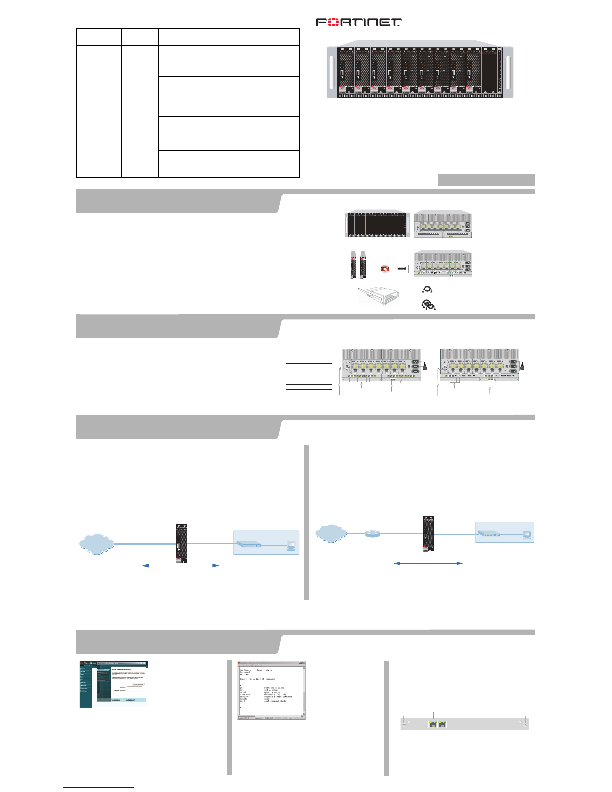
Connect the FortiGate-4000 unit to a power outlet and to the internal and external networks.
NAT/Route mode
In NAT/Route mode, the FortiGate-4000 is visible to the network. The Internal and
external interfaces are on different subnets. Each interface must be configure with an
IP address that is valid for the network that it is connected to.
You would typically use NAT/Route mode when the FortiGate-400 unit is deployed as a
gateway between private and public networks. In its default NAT/Route mode
configuration, the module functions as a firewall. Firewall policies control
communications through the FortiGate-400 unit. No traffic can pass through the
FortiGate-4000 unit until you add firewall policies.
In NAT/Route mode, firewall policies can operate in NAT mode or in Route mode. In
NAT mode, the FortiGate-400 unit performs network address translation before IP
packets are sent to the destination network. In Route mode, no translation takes place.
Transparent mode
In Transparent mode, the FortiGate-4000 unit is invisible to the network. All of its
interfaces are on the same subnet. You only have to configure a management IP
address so that you can make configuration changes.
You would typically use the FortiGate-4000 unit in Transparent mode on a private
network behind an existing firewall or behind a router. In its default Transparent mode
configuration, the unit functions as a firewall. No traffic can pass through the
FortiGate-4000 unit until you add firewall policies.
You can connect two network segments to the FortiGate-4000 unit to control traffic
between these network segments.
Internal network
192.168.1.3
External
204.23.1.5
NAT mode policies controlling
traffic between internal and
external networks.
Internet
FortiGate-4000 unit
in NAT/Route mode
Internal
192.168.1.99
POWER ON/OFF
LAN 1LAN 2
PWR/KVMSTATUS
KVM/ACCESS
Internal network
192.168.1.3
204.23.1.5
Transparent mode policies controlling
traffic between internal and
external networks.
Internet
FortiGate-4000 unit
in Transparent mode
Internal
192.168.1.2
Management IP
192.168.1.1
External
(Firewall, router)
Gateway to
public newtwork
POWER ON/OFF
LAN 1LAN 2
PWR/KVMSTATUS
KVM/ACCESS
Before beginning to configure the FortiGate-4000 unit, you need to plan how to integrate the unit
into your network. Your configuration plan is dependent upon the operating mode that you select:
NAT/Route mode (the default) or Transparent mode.
Web-based
manager &
Setup Wizard
The FortiGate web-based
manager Setup Wizard
guides you through the
initial configuration steps.
Use it to configure the administrator password, the
interface addresses, the default gateway address, and
the DNS server addresses. Optionally, use the Setup
Wizard to configure the internal server settings for
NAT/Route mode.
Requirements:
• The Ethernet connection between the FortiGate4000 and management computer.
• Internet Explorer version 4.0 or higher on the
management computer.
Command Line
Interface (CLI)
The CLI is a full-featured
management tool.
Use it to configure the
administrator password,
the interface addresses,
the default gateway
address, and the DNS
server addresses. To
configure advanced settings, see the “Getting Started”
chapter in Documentation CD-ROM.
Requirements:
• The serial connection between the FortiGate-4000
and management computer.
• A terminal emulation application (HyperTerminal for
Windows) on the management computer.
Out of band management module
You can manage FortiGate-4000 units by connecting to
the 10/100 out of band management module, which
provides out of band ethernet management connections
for all of the FortiGate-4000 units installed in the
FortiGate-4000 chassis.
Requirements:
• A computer with an ethernet connection.
• Internet Explorer version 4.0 or higher.
• A crossover cable or an ethernet hub and two
ethernet cables.
4000
LAN 2LAN 1
LAN 1
LAN 2
Mounting Knot Mounting Knot
Choose among three different tools to configure the FortiGate-4000.
QuickStart Guide
FortiGate-4000
© Copyright 2004 Fortinet Incorporated. All rights reserved.
Trademarks
Products mentioned in this document are trademarks or registered trademarks of their respective holders.
Regulatory Compliance
FCC Class A Part 15 CSA/CUS
03 November 2004
For technical support please visit http://www.fortinet.com.
Check that the package contents are complete.
See the “Getting Started” chapter of the FortiGate-4000 Installation and
Configuration Guide for details about how to perform the following steps.
1. Mount the FortiGate-4000 chassis with the mounting rail in a rack or
cabinet with a depth of more than 700 mm, excluding the front door depth.
2. Connect the network cables.
3. Connect the power cables to power outlets.
4. Turn on all FortiGate-4000 power switches.
5. Turn on each FortiBlade-4010.
Checking the package contents
Checking the package contents
1
Connecting the FortiGate-4000
2
Planning the configuration
3
Choosing a configuration tool
4
The FortiGate-4000 package consists of two or more packages. One or more of the packages
contains two FortiBlade-4010 modules.
The other package contains:
• FortiGate-4000 chassis which includes the following components (already installed):
1 KVM switch module, 10 FortiGate-4000 empty slot covers, 1 management module, 7 power
supply modules, 4 cooling fan trays, 2 pass-through interface modules with ten 1000Base-T
connectors (FortiGate-4000P), or 2 switched interface modules with two 1000Base-T or SFP
(FortiGate-4000S) connectors, one 10/100 out of band management module with two
10/100Base-T connectors.
• Three power cables,
• One RJ-45 to DB-9 serial cable (only the black header works with the FortiGate-4000),
• One FortiGate-4000 QuickStart Guide,
• One Documentation CD-ROM containing Fortinet user documentation.
Default IP Addresses (Nat/Route mode)
Internal
External
Out of band
192.168.1.99
192.168.100.99
172.16.1.2
Default IP Addresses (Transparent mode)
Management IP
10.10.10.1
Ethernet cables connect
FortiGate-4000 internal interfaces
to LAN or switch on internal network
Ethernet cables
connect FortiGate-4000
external interfaces to the Internet
LAN 9LAN 10 LAN 8 LAN 7 LAN 6 LAN 5 LAN 4 LAN 3 LAN 2 LAN 1 LAN 9LAN 10 LAN 8 LAN 7 LAN 6 LAN 5 LAN 4 LAN 3 LAN 2 LAN 1
LAN 2LAN 1
ONON OFFOFF
ERRERR
RJ-45 to DB-9 cable
connects to
management computer
FortiGate-4000P rear panel
Ethernet cable connect to out of
band management network
LAN 2LAN 1
ONON OFFOFF
ERRERR
LAN 1LAN 2COM
SFP
SFP HiGig OUT HiGig IN
ON OFF
LAN 1LAN 2COM
SFP
SFP HiGig OUT HiGig IN
ON OFF
FortiGate-4000S rear panel
RJ-45 to DB-9 cable
connects to
management computer
Ethernet or fibre optic cables
connect
FortiGate-4000 external interfaces
to the Internet
Ethernet or fibre optic cables
connect FortiGate-4000 internal
interfaces to LAN or switch on
internal network
Power cables
connect to
power outlets
Out of band
172.16.1.2
Power cables
connect to
power outlets
Ethernet cable connect to out of
band management network
FortiGate-4000P Chassis (back view)
POWER ON/OFF
LAN 1LAN 2
PWR/KVMSTATUS
KVM/ACCESS
POWER ON/OFF
LAN 1LAN 2
PWR/KVMSTATUS
KVM/ACCESS
FortiBlade-4010 modules
RJ-45 to DB-9
serial cable
Power Cables (3)
LAN 9LAN 10 LAN 8 LAN 7 LAN 6LAN 5 LAN 4 LAN 3 LAN 2 LAN 1 LAN 9LAN 10 LAN 8 LAN 7 LAN 6LAN 5 LAN 4 LAN 3 LAN 2 LAN 1
ONON OFFOFF
ERRERR
LAN 2LAN 1
FortiGate-4000S Chassis (back view)
LAN 2LAN 1
LAN 1LAN 2COM
SFP
SFP HiGig OUT HiGig IN
ON OFF
LAN 1LAN 2COM
SFP
SFP HiGig OUT HiGig IN
ON OFF
ONON OFFOFF
ERRERR
FortiGate-4000 Chassis (front view)
KVM
ALARM
Documentation
(CD and QuickStart Guide)
FortiGate-4000
QuickStart Guide
Copyright 2003 Fortinet Incorporated. All rights reserved.
Trademarks
Products mentioned in this document are trademarks.
KVM
ALARM
Mounting rail and rail mounting locations
Refer to the Documentation CD-ROM for information on how to control traffic, and how to configure HA, antivirus protection, Web content filtering, Spam filtering, intrusion
prevention (IPS), and virtual private networking (VPN).
01-28005-0042-20041103
Page 2
Using the out of band
management module
Connect the 10/100 out of band management module to your network. Power on the FortiGate-4000 unit that you want to
connect to. When first installed, all FortiGate-4000 units installed in the FortiGate-4000 chassis have the same out of band
management IP addresses. To connect to a specific FortiGate-4000 unit, you must turn on the power for this FortiGate-4000
unit. The power to all of the other FortiGate-4000 units must be turned off.
NAT/Route mode
Transparent mode
The management IP address and netmask must be valid for the network that the
FortiGate-4000 unit is connected to.
General settings
A default gateway is required for the FortiGate unit to route connections to the Internet.
Internal Interface:
IP:
____.____.____.____
Netmask:
____.____.____.____
External
Interface:
IP:
____.____.____.____
Netmask:
____.____.____.____
Out of band
management
Interface
IP:
____.____.____.____
Netmask:
____.____.____.____
Management IP:
IP:
____.____.____.____
Netmask:
____.____.____.____
Administrator password:
Network Settings:
Default Gateway:
____.____.____.____
Primary DNS Server:
____.____.____.____
Secondary DNS Server:
____.____.____.____
Using the
Setup Wizard
Use these tables to record your FortiGate-4000 configuration. You can record NAT/Route or
Transparent mode settings and general settings that apply to both modes.
To connect to the out of band management module
1. Set the IP address of the management computer to the static IP address
172.16.1.3 and a netmask of 255.255.255.0.
2. Start Internet Explorer and browse to the address https://172.16.1.2 (remember to
include the “s” in https://).
3. Type admin in the Name field and select Login.
To change the out of band management IP address
1. After logging into the FortiGate-4000 unit, go to System > Network > OOB
Management.
2. Change the IP/Netmask addresses.
Using the
Command Line Interface
1. Connect to the CLI of each FortiGate-4000 by connecting to the management interface module. Use the KVM switch to
select which FortiGate-4000 you are connecting to.
2. Start a terminal emulation program (HyperTerminal) on the management computer. Use these settings:
Baud Rate (bps) 9600, Data bits 8, Parity None, Stop bits 1, and Flow Control None.
3. At the FortiGate Login: prompt, type admin and press Enter twice.
Steps for using the configuration tool that you have chosen. For more information, see the
“Getting Started” chapter of the FortiGate-4000 Installation and Configuration Guide on the
Documentation CD-ROM.
Collecting information
5
Configuring the FortiGate-4000
6
1. Connect the FortiGate-4000 internal interface to the management computer Ethernet interface. Use a cross-over Ethernet cable to connect the
devices directly. Use straight-through Ethernet cables to connect the devices through a hub or switch.
2. Configure the management computer to be on the same subnet as FortiGate-4000 internal interface. To do this, change the IP address of the
management computer to 192.168.1.2 and the netmask to 255.255.255.0.
3. To access the FortiGate web-based manager, start Internet Explorer and browse to https://192.168.1.99 (remember to include the “s” in https://).
4. Type admin in the Name field and select Login.
NAT/Route mode
1. Configure the internal interface.
config system interface
edit internal
set mode static
set ip <intf_ip> <netmask_ip>
end
2. Repeat to configure the external interface.
config system interface
edit external
set mode static
set ip <intf_ip> <netmask_ip>
end
3. Configure the primary and secondary DNS server IP addresses.
config system dns
set primary <dns-server_ip>
set secondary <dns-server_ip>
end
4. Configure the default gateway.
config router static
edit 1
set gateway <gateway_ip>
end
Transparent mode
1. Change from NAT/Route mode to Transparent mode.
config system global
set opmode transparent
end
2. Wait a moment and then log in again at the prompt.
3. Configure the Management IP address.
config system manageip
set ip <mng_ip> <netmask>
end
Configure the DNS server IP address.
config system dns
set primary <dns-server_ip>
set secondary <dns-server_ip>
end
4. Configure the default route.
config router static
edit 1
set gateway <gateway_ip>
end
Note: If you change the IP address of the internal interface (NAT/Route mode) or management IP address (Transparent mode), you must use this address to reconnect to the web-based manager and Setup
Wizard. You might also have to change the IP address of the management computer to be on the same subnet as the new IP address.
NAT/Route mode
Using the Setup Wizard
To configure the FortiGate-4000 unit using the Setup Wizard, select
the Easy Setup Wizard button and follow the prompts.
Using the web-based manager
To change the administrator password
1. Go to System > Admin > Administrators.
2. Select Change Password for the admin administrator and enter a new password.
To configure interfaces
1. Go to System > Network > Interface.
2. Select the edit icon for each interface to configure.
3. Set the addressing mode for the interface. (see the online help for information.)
•For manual addressing, enter the IP address and netmask for the interface.
•For DHCP addressing, select DHCP and any required settings.
•For PPPoE addressing, select PPPoE, and enter the username and password and
any other required settings.
To configure the Primary and Secondary DNS server IP addresses
1. Go to System > Network > DNS, enter the Primary and Secondary DNS IP
addresses that you recorded above and select Apply.
To configure a Default Gateway
1. Go to Router > Static and select Edit icon for the static route.
2. Set Gateway to the Default Gateway IP address that you recorded above and select
OK.
Transparent mode
To switch from NAT/route mode to transparent mode
1. Go to System > Status, select Change beside Operation Mode, and select OK.
2. Change the IP address of the management computer to 10.10.10.2 and use
Internet Explorer to browse to https://10.10.10.1.
Using the Setup Wizard
To configure the FortiGate-4000 unit using the Setup Wizard, select the Easy Setup
Wizard button and follow the prompts.
Using the web-based manager
To change the administrator password using the web-based manager
1. Go to System > Admin > Administrators.
2. Select Change Password for the admin administrator and enter a new password.
To configure the management interface using the web-based manager
1. Go to System > Network > Management.
2. Enter the Management IP address and netmask that you recorded above.
3. Select administrative access options if required and select OK.
To configure the Primary and Secondary DNS server IP addresses
1. Go to System > Network > DNS, enter the Primary and Secondary DNS IP
addresses that you recorded above and select Apply.
To configure a Default Gateway
1. Go to System > Network > Management.
2. Set Default Gateway to the Default Gateway IP address that you recorded above
and select OK.
Select the
Easy Setup Wizard
Congratulations!
You have finished configuring the basic settings. Your network is now protected from
Internet-based threats. To explore the full range of configuration options, see the online help
or the Documentation CD-ROM.
Completing the configuration
7
• To restart the unit, go to System > Maintenance >
ShutDown and select Reboot.
• To reset the unit, go to System > Maintenance >
Shutdown and select Reset to factory default.
Restarting the FortiGate-4000
Should you mistakenly change a network setting and cannot connect to the
unit, reboot the unit and try again or to set the unit back to factory defaults and
start over again.
CLI:
execute reboot
CLI:
execute factoryreset
 Loading...