

Page 1
© Copyright 2008 Fortinet Incorporated. All rights reserved.
Products mentioned in this document are trademarks or registered trademarks of their respective holders.
Regulatory Compliance
FCC Class A Part 15 CSA/CUS
4 April 2008
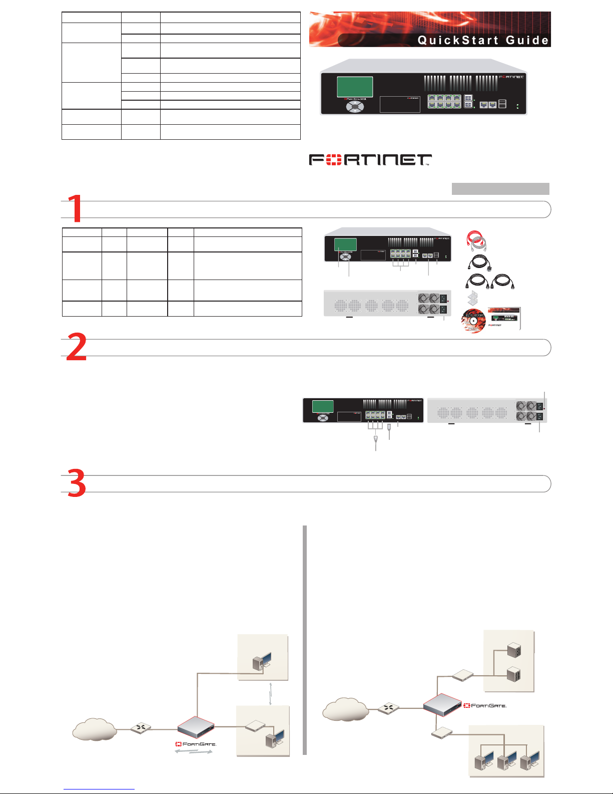
Checking the Package Contents
Connecting
Planning the Configuration
Intern et
Router
Int erna l
net work
Port 3
10.10.10.1
10.10.10.2
Int erna l Net work
192.168.1.3
Port 2
192.168.1.99
Routing policies controlling
traffic between internal
networks.
Port 1
204.23.1.5
NAT mode policies controlling
traffic between internal
and external networks.
Intern et
Router
DMZ net
w
ork
Web Server
Mail Server
Int erna l
net work
Hub or switch
Port 3
Poirt 1
Port 2
POWER
STATUS
Esc Enter
USB
AUX
CONSOLE
8642
7531
10
9
POWER
STATUS
Esc Enter
USB
AUX
CONSOLE
8642
7531
10
9
1-8 Coppe r Ports
9/10
Fiber Por ts
USB
Serial an d
Modem Con nections
Back
Front
Power
Connectio ns
Power Cab les (2)
Rack-Moun t Brackets
Documenta tion
Ethernet Cables:
Orange - Crossover
Grey - St raight-thro ugh
USER MANUAL
LCD
Display
Control
Buttons
RJ-45 to
DB-9 Seri al Cable
FortiGate-3600A
Copyright 2008 Fortinet Incorporat ed. All rig hts reserved .
Trademarks
Products mentioned in this documen t are trade marks.
Qui c k St a rt G ui d e
POWER
STATUS
Esc Enter
USB
AUX
CONSOLE
8642
7531109
POWER
STATUS
Esc Enter
USB
AUX
CONSOLE
8642
7531
10
9
Straig ht-through Ethernet cab les
connec t to the In ternet or ot her
networ ks
RJ-45 to DB-9 cab le connects
to ser ial port on management computer
Fiber optic cable
connec ts
to int ernal netwo rk or Intern et
Power cable s conn ect
to pow er ou tlets
Power alarm
reset butto n
Connect the FortiGate unit to a power outlet and to the internal and external networks.
Place the unit on a stable surface.
The FortiGate unit requires 1.5 inches (3.75 cm) clearance above and on each side
to allow for cooling.
Connect the power cables to the back of the FortiGate unit, then plug the power
cable into the power supply.
MAIN MENU appears when the unit is up and running.
If only one power supply is connected, an audible alarm sounds to indicate a failed
power supply. To stop this alarm, press the red alarm cancel button.
•
•
•
•
•
Before beginning to congure the FortiGate unit, you need to plan how to integrate the unit into your network. Your conguration plan is dependent upon the operating mode that you select:
NAT/Route mode (the default) or Transparent mode. Refer to the Documentation CD-ROM for information on how to control trafc, and how to congure HA, antivirus protection, FortiGuard,
Web content ltering, Spam ltering, intrusion prevention (IPS), and virtual private networking (VPN).
NAT/Route mode
In NAT/Route mode, each FortiGate unit is visible to the network that it is connected to. All
of its interfaces are on different subnets. Each interface connected to a network must be
congured with an IP address that is valid for that network.
You would typically use NAT/Route mode when the FortiGate unit is deployed as a gateway
between private and public networks. In its default NAT/Route mode conguration, the unit
functions as a rewall. Firewall policies control communications through the FortiGate unit.
No trafc can pass through the FortiGate unit until you add rewall policies.
In NAT/Route mode, rewall policies can operate in NAT mode or in Route mode. In NAT
mode, the FortiGate unit performs network address translation before IP packets are sent to
the destination network. In Route mode, no translation takes place.
Transparent mode
In Transparent mode, the FortiGate unit is invisible to the network. All of its interfaces are on
the same subnet. You only have to congure a management IP address so that you can make
conguration changes.
You would typically use the FortiGate unit in Transparent mode on a private network behind
an existing rewall or behind a router. In its default Transparent mode conguration, the unit
functions as a rewall. No trafc can pass through the FortiGate unit until you add rewall
policies.
You can connect up to four network segments to the FortiGate unit to control trafc between
these network segments.
FortiGate-3600A
01-30006-0344-20080404
LED State Description
Power
Green The FortiGate unit is on.
Off The FortiGate unit is off.
Port 1 to 8
(Left LED)
Green The correct cable is in use and the connected equipment
has power.
Flashing
Green
Network activity at this interface.
Off No link established.
Port 1 to 8
(Right LED)
Green Connection at 1 GB
Amber Connection at 100 MB
Off Connection at 10 MB
Port 9 and 10
Green The correct cable is in use and the connected equipment
has power.
Flashing
Green
Network activity at this interface.
Connector Type Speed Protocol Description
Ports 1 to 8 RJ-45 1000 Base-T Ethernet Copper gigabit connection to 10/100/1000
copper networks.
Ports 9 and 10 LC SFP 1000Base-SX Ethernet Multimode ber optic connections to gigabit
optical networks for small packet performance required for voice, video and other
multimedia streaming applications.
CONSOLE RJ-45 9600 bps RS-232
serial
Optional connection to the management
computer. Provides access to the command
line interface (CLI).
USB USB USB Optional connection to a FortiUSB key for
rmware backup and installation.
Page 2
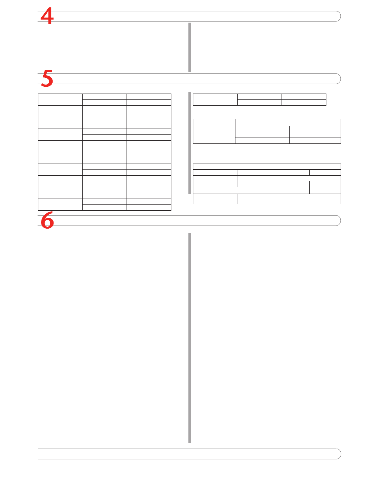
Completing the Configuration
7
Congratulations!
You have nished conguring the basic settings. Your network is now protected from Internetbased threats. To explore the full range of conguration options, see the online help or the
Documentation CD-ROM.
Visit these links for more information and documentation for your Fortinet product.
Technical Documentation - http://docs.forticare.com
Fortinet Knowledge Center - http://kc.forticare.com
Fortinet Technical Support - http://support.fortinet.com
•
•
•
Collecting Information
NAT/Route Mode
Port 1 IP: ____.____.____.____
Netmask: ____.____.____.____
Port 2 IP: ____.____.____.____
Netmask: ____.____.____.____
Port 3 IP: ____.____.____.____
Netmask: ____.____.____.____
Port 4 IP: ____.____.____.____
Netmask: ____.____.____.____
Port 5 IP: ____.____.____.____
Netmask: ____.____.____.____
Port 6 IP: ____.____.____.____
Netmask: ____.____.____.____
Port 7 IP: ____.____.____.____
Netmask: ____.____.____.____
Port 8 IP: ____.____.____.____
Netmask: ____.____.____.____
Port 9 IP: ____.____.____.____
Netmask: ____.____.____.____
Port 10 IP: ____.____.____.____
Netmask: ____.____.____.____
Transparent mode
Management IP IP: ____.____.____.____
Netmask: ____.____.____.____
General settings
Administrator password
Network Settings Default Gateway:
____.____.____.____
Primary DNS Server: ____.____.____.____
Secondary DNS Server: ____.____.____.____
A default gateway is required for the FortiGate unit to route connections to the Internet.
Factory default settings
NAT/Route mode Transparent mode
Port 1 192.168.1.99 Management IP 0.0.0.0
Port 2 192.168.2.99 Administrative account settings
Ports 3 to 10 0.0.0.0 User name admin
Password (none)
DHCP server on Internal
interface
192.168.1.110 – 192.168.1.210
Configuring the FortiGate Unit
Web-based Manager
Connect the FortiGate internal interface to a management computer Ethernet interface.
Use a cross-over Ethernet cable to connect the devices directly. Use straight-through
Ethernet cables to connect the devices through a hub or switch.
Congure the management computer to be on the same subnet as the internal
interface of the FortiGate unit. To do this, change the IP address of the management
computer to 192.168.1.2 and the netmask to 255.255.255.0.
To access the FortiGate web-based manager, start Internet Explorer and browse to
https://192.168.1.99 (remember to include the “s” in https://).
Type admin in the Name eld and select Login.
NAT/Route mode
To change the administrator password
Go to System > Admin > Administrators.
Select Change Password for the admin administrator and enter a new password.
To congure interfaces
Go to System > Network > Interface.
Select the edit icon for each interface to congure.
Set the addressing mode for the interface. (See the online help for information.)
For manual addressing, enter the IP address and netmask for the interface.
For DHCP addressing, select DHCP and any required settings.
For PPPoE addressing, select PPPoE, and enter the username and password
and any other required settings.
To congure the Primary and Secondary DNS server IP addresses
Go to System > Network > Options, enter the Primary and Secondary DNS IP addresses that you recorded above and select Apply.
To congure a Default Gateway
Go to Router > Static and select Edit icon for the static route.
Set Gateway to the Default Gateway IP address you recorded above and select OK.
Transparent mode
To switch from NAT/route mode to transparent mode
Go to System > Cong > Operation Mode and select Transparent.
Set the Management IP/Netmask to 192.168.1.99/24.
Set a default Gateway and select Apply.
To change the administrator password
Go to System > Admin > Administrators.
Select Change Password for the admin administrator and enter a new password.
To change the management interface
Go to System > Cong > Operation Mode.
Enter the Management IP address and netmask that you recorded above and select
Apply.
To congure the Primary and Secondary DNS server IP addresses
Go to System > Network > Options, enter the Primary and Secondary DNS IP addresses that you recorded above and select Apply.
1.
2.
3.
4.
1.
2.
1.
2.
3.
•
•
•
1.
1.
2.
1.
2.
3.
1.
2.
1.
2.
1.
Command Line Interface
Use the RJ-45 to DB9 serial cable to connect the FortiGate Console port to the management computer serial port.
Start a terminal emulation program (HyperTerminal) on the management computer. Use
these settings:
Baud Rate (bps) 9600, Data bits 8, Parity None, Stop bits 1, and Flow Control None.
At the Login: prompt, type admin and press Enter twice (no password required).
NAT/Route mode
Congure the FortiGate internal interface.
cong system interface
edit internal
set ip <intf_ip>/<netmask_ip>
end
Repeat to congure each interface, for example, to congure the WAN1 interface.
cong system interface
edit wan1
...
Congure the primary and secondary DNS server IP addresses.
cong system dns
set primary <dns-server_ip>
set secondary <dns-server_ip>
end
Congure the default gateway.
cong router static
edit 1
set gateway <gateway_ip>
end
Transparent Mode
Change from NAT/Route mode to Transparent mode and congure the Management IP
address.
cong system settings
set opmode transparent
set ip <mng_ip>/<netmask>
set gateway <gateway_ip>
end
Congure the DNS server IP address.
cong system dns
set primary <dns-server_ip>
set secondary <dns-server_ip>
end
1.
2.
3.
4.
1.
2.
3.
4.
1.
2.
Choosing a Configuration Tool
Web-based manager
The FortiGate web-based manager is an easy to use management tool.
Use it to congure the administrator password, the interface and default gateway addresses,
and the DNS server addresses.
Requirements:
An Ethernet connection between the FortiGate unit and management computer.
Internet Explorer 6.0 or higher on the management computer.
•
•
Command Line Interface (CLI)
The CLI is a full-featured management tool. Use it to congure the administrator password,
the interface addresses, the default gateway address, and the DNS server addresses. To
congure advanced settings, see the Documentation CD-ROM.
Requirements:
The RJ-45 to DB-9 serial connection between the FortiGate unit and management
computer.
A terminal emulation application (HyperTerminal for Windows) on the management
computer.
•
•
 Loading...