

Page 1
© Copyright 2006 Fortinet Incorporated. All rights reserved.
Products mentioned in this document are trademarks or registered trademarks of their respective holders.
Regulatory Compliance
FCC Class A Part 15 CSA/CUS
5 December 2006
2625
WAN1 WAN2 CONSOLEUSB
1 3 5 9 117
2 4 6 1 0 128
13 15 17 21 2319
14 16 18 22 2420
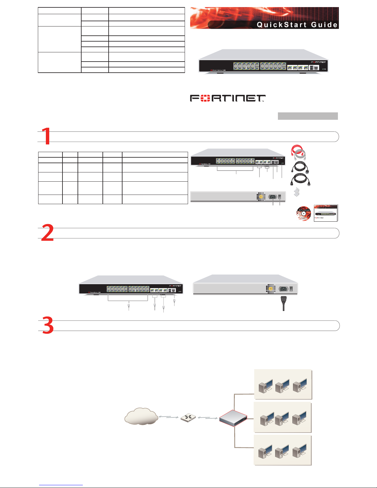
Checking the Package Contents
Connecting
Planning the Configuration
Connector Type Speed Protocol Description
Ports 1 to 24 RJ-45 10/100 Base-T Ethernet A 24-port switch connection.
Port 25 and 26 RJ-45 1000 Base-T Ethernet Copper gigabit connection to 10/100/1000
copper networks.
WAN1 and
WAN2
RJ-45 10/100 Base-T Ethernet Redundant connections to the Internet.
Console RJ-45 9600 Bps RS-232 Optional connection to the management
computer. Provides access to the command
line interface (CLI).
USB USB USB Optional connection for the FortiUSB key,
modem or backup operation.
Place the unit on a stable surface, or mounted on a standard 19-inch rack unit.
The FortiGate-224B requires 1U of vertical space on the rack.
The FortiGate-224B requires 1.5 inches (3.75 cm) clearance above and on each side to allow for cooling.
Make sure the power switch on the back of the unit is turned off before connecting the power and network cables.
•
•
•
•
Connect the FortiGate unit to a power outlet and to the internal and external networks.
The FortiGate-224B unit runs in NAT/Route mode only. In NAT/Route mode, the FortiGate unit is visible to the network
that it is connected to.
In its default NAT/Route mode conguration, the unit functions as a rewall as well as a 24 port switch. Firewall policies
control communications through the FortiGate unit.
No trafc can pass through the FortiGate unit until you add rewall policies. In NAT/Route mode, rewall policies can
operate in NAT mode or in Route mode. In NAT mode, the FortiGate unit performs network address translation before
IP packets are sent to the destination network. In Route mode, no translation takes place.
Refer to the Documentation CD-ROM for information on how to control trafc, and how to congure HA, antivirus
protection, FortiGuard, Web content ltering, Spam ltering, intrusion prevention (IPS), and virtual private networking
(VPN).
FortiGate-224B
01-30003-0332-20061205
LED State Description
Power
Green The FortiGate unit is on.
Off The FortiGate unit is off.
Ports 1 to 24
WAN1
WAN2
Amber The correct cable is in use and the connected
equipment has power.
Flashing Amber Network activity at this interface.
Green The interface is connected at 100Mbps.
Off No link established.
Port 25 and 26
Amber The correct cable is in use and the connected
equipment has power.
Flashing Amber Network activity at this interface.
Green The interface is connected at 1000Mbps.
2625
WAN1 WAN2 CONSOLEUSB
1 3 5 9 117
2 4 6 10 128
13 15 17 21 2319
14 16 18 22 2420
Power C able
Rack-Mo unt Bracket s
Etherne t Cables:
Orange - Crossover
Grey - Straight-th rough
Front
Interna l
(24-por t switch)
Power
LED
DMZ
1, 2
WAN
1, 2
Back
Power
Connect ion
Power
Switch
USB
Serial
Port
RJ-45 t o
DB-9 Se rial Cable
Docume ntation
FortiGate-224B
Copyright 2006 Fortinet Incor porated. Al l rights re served.
Trademarks
Products mentioned in this do cument are trademarks.
Qu ic k St a r t G u id e
2625
WAN1 WAN2 CONSOLEUSB
1 3 5 9 117
2 4 6 10 128
13 15 17 21 2319
14 16 18 22 2420
2625
WAN1 WAN2 CONSOLEUSB
1 3 5 9 1 17
2 4 6 10 128
13 15 17 21 2319
14 16 18 22 2420
Straight -through Et hernet cabl es for
redundan t connectio n to Intern et
O
ptional Giga
bit conn ections
Straight- through
Ethernet cables
connect to computer s on intern al network
Optional RJ-45 seri al cable co nnects to
manageme nt computer
Power ca ble connect s to power outlet
For t iG at e
Inter net
Router
Net work 1
Net work 2
WAN1
Net work 3
Page 2
Completing the Configuration
7
Congratulations!
You have nished conguring the basic settings. Your network is now protected from Internetbased threats. To explore the full range of conguration options, see the online help or the
Documentation CD-ROM.
Visit these links for more information and documentation for your Fortinet product.
Technical Documentation - http://docs.forticare.com
Fortinet Knowledge Center - http://kc.forticare.com
Fortinet Technical Support - http://support.fortinet.com
•
•
•
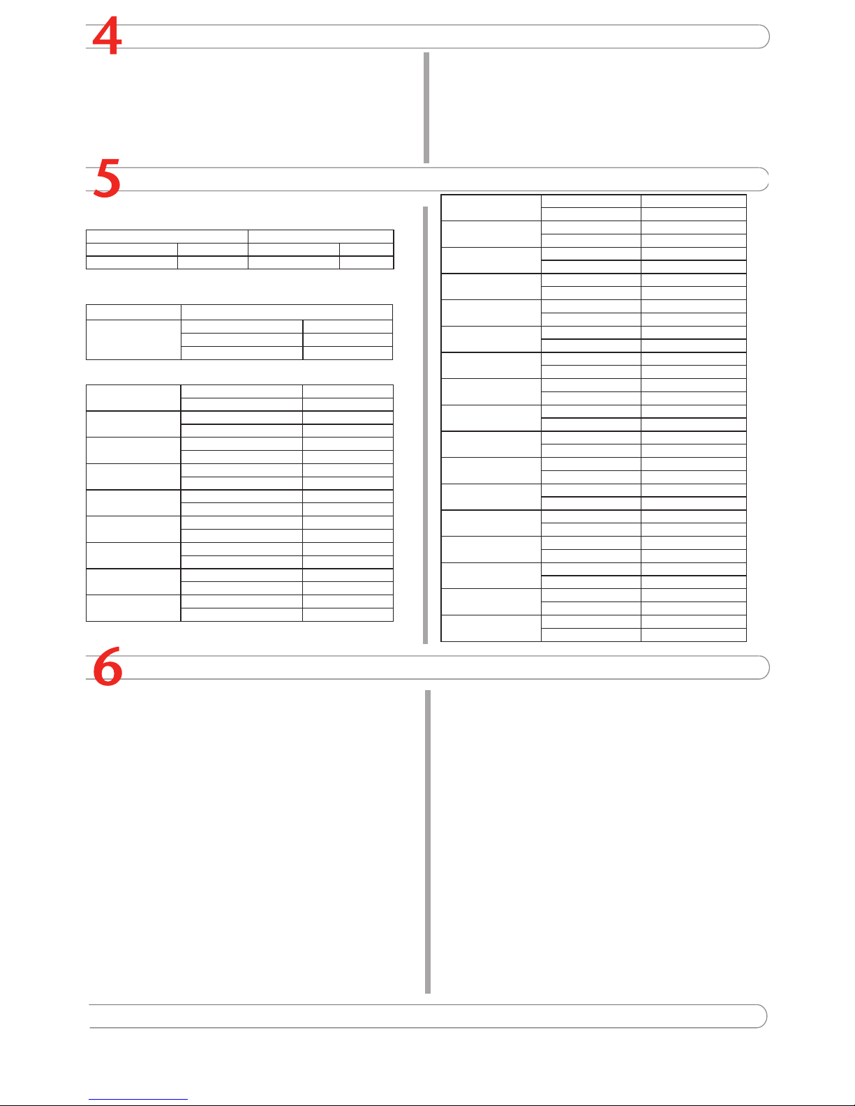
Configuring the FortiSwitch Unit
WAN1 IP: ____.____.____.____
Netmask: ____.____.____.____
WAN2 IP: ____.____.____.____
Netmask: ____.____.____.____
Port 1 IP: ____.____.____.____
Netmask: ____.____.____.____
Port 2 IP: ____.____.____.____
Netmask: ____.____.____.____
Port 3 IP: ____.____.____.____
Netmask: ____.____.____.____
Port 4 IP: ____.____.____.____
Netmask: ____.____.____.____
Port 5 IP: ____.____.____.____
Netmask: ____.____.____.____
Port 6 IP: ____.____.____.____
Netmask: ____.____.____.____
Port 7 IP: ____.____.____.____
Netmask: ____.____.____.____
Factory default settings
NAT/Route mode Administrative account settings
WAN1 192.168.1.99 User name admin
WAN2 0.0.0.0 Password (none)
General settings
Administrator password:
Network Settings: Default Gateway:
____.____.____.____
Primary DNS Server: ____.____.____.____
Secondary DNS Server: ____.____.____.____
A default gateway is required for the FortiGate unit to route connections to the Internet.
Web-based Manager
Connect to the FortiGate WAN1 interface to a management computer Ethernet interface. Use a cross-over Ethernet cable to connect the devices directly. Use straightthrough Ethernet cables to connect the devices through a hub or switch.
Congure the management computer to be on the same subnet as the internal
interface of the FortiGate unit. To do this, change the IP address of the management
computer to 192.168.1.2 and the netmask to 255.255.255.0.
To access the FortiGate web-based manager, start Internet Explorer and browse to
https://192.168.1.99 (remember to include the “s” in https://).
Type admin in the Name eld and select Login.
To change the administrator password
Go to System > Admin > Administrators.
Select Change Password for the admin administrator and enter a new password.
To congure interfaces
Go to System > Network > Interface.
Select the edit icon for each interface to congure.
Set the addressing mode for the interface. (See the online help for information.)
For manual addressing, enter the IP address and netmask for the interface.
For DHCP addressing, select DHCP and any required settings.
For PPPoE addressing, select PPPoE, and enter the user name and password
and any other required settings.
To congure the Primary and Secondary DNS server IP addresses
Go to System > Network > Options, enter the Primary and Secondary DNS IP addresses that you recorded above and select Apply.
To congure a Default Gateway
Go to Router > Static and select Edit icon for the static route.
Set Gateway to the Default Gateway IP address you recorded above and select OK.
1.
2.
3.
4.
1.
2.
1.
2.
3.
•
•
•
1.
1.
2.
Command Line Interface
Use the RJ-45 to DB-9 serial cable and converter to connect the FortiGate Console port
to the management computer serial port.
Start a terminal emulation program (HyperTerminal) on the management computer.
Use these settings: Baud Rate (bps) 9600, Data bits 8, Parity None, Stop bits 1, and
Flow Control None.
At the Login: prompt, type admin and press Enter twice (no password required).
Congure the FortiGate internal interface.
config system interface
edit internal
set ip <intf_ip>/<netmask>
end
Congure the FortiGate external interface.
config system interface
edit wan1
set ip <intf_ip>/<netmask>
Congure the primary and secondary DNS server IP addresses.
config system dns
set primary <dns-server_ip>
set secondary <dns-server_ip>
end
Congure the default gateway.
config router static
edit 1
set gateway <gateway_ip>
end
1.
2.
3.
1.
2.
3.
4.
Collecting Information
Choosing a Configuration Tool
Web-based manager
The FortiGate web-based manager is an easy to use management tool. Use it to congure
the administrator password, the interface and default gateway addresses, and the DNS
server addresses.
Requirements:
An Ethernet connection between the FortiGate unit and management computer.
Internet Explorer 6.0 or higher on the management computer.
•
•
Command Line Interface (CLI)
The CLI is a full-featured management tool. Use it to congure the administrator password,
the interface addresses, the default gateway address, and the DNS server addresses. To
congure advanced settings, see the Documentation CD-ROM.
Requirements:
The RJ-45 to DB-9 serial connection between the FortiGate unit and management
computer.
A terminal emulation application (HyperTerminal for Windows) on the management
computer.
•
•
Port 8 IP: ____.____.____.____
Netmask: ____.____.____.____
Port 9 IP: ____.____.____.____
Netmask: ____.____.____.____
Port 10 IP: ____.____.____.____
Netmask: ____.____.____.____
Port 11 IP: ____.____.____.____
Netmask: ____.____.____.____
Port 12 IP: ____.____.____.____
Netmask: ____.____.____.____
Port 13 IP: ____.____.____.____
Netmask: ____.____.____.____
Port 14 IP: ____.____.____.____
Netmask: ____.____.____.____
Port 15 IP: ____.____.____.____
Netmask: ____.____.____.____
Port 16 IP: ____.____.____.____
Netmask: ____.____.____.____
Port 17 IP: ____.____.____.____
Netmask: ____.____.____.____
Port 18 IP: ____.____.____.____
Netmask: ____.____.____.____
Port 19 IP: ____.____.____.____
Netmask: ____.____.____.____
Port 20 IP: ____.____.____.____
Netmask: ____.____.____.____
Port 21 IP: ____.____.____.____
Netmask: ____.____.____.____
Port 22 IP: ____.____.____.____
Netmask: ____.____.____.____
Port 23 IP: ____.____.____.____
Netmask: ____.____.____.____
Port 24 IP: ____.____.____.____
Netmask: ____.____.____.____
 Loading...