

Fortinet FON-350i Start Manual

FON-350i Telephone
Start Guide

FON-350i Telephone Start Guide
Revision 2
5 April 2012
27-400-166715-20120405
© Copyright 2012 Fortinet, Inc. All rights reserved. Contents and terms are
subject to change by Fortinet without prior notice. Reproduction or
transmission of this publication is encouraged.
Trademarks
The names of actual companies and products mentioned herein may be the
trademarks of their respective owners.
Visit these links for more information and documentation for your Fortinet
products:
Fortinet Knowledge Base - http://kb.fortinet.com
Technical Documentation - http://docs.fortinet.com
Training Services - http://campus.training.fortinet.com
Technical Support - http://support.fortinet.com
You can report errors or omissions in this or any Fortinet technical document
to techdoc@fortinet.com.

FON-350i Telephone Start Guide
FON-350i Telephone Start Guide v2 iii
Contents
Introduction 1
Phone Features . . . . . . . . . . . . . . . . . . . . . . . . . . . . . . . 1
Requirements . . . . . . . . . . . . . . . . . . . . . . . . . . . . . . . . 1
About this Guide . . . . . . . . . . . . . . . . . . . . . . . . . . . . . . . 2
Flexible Key States . . . . . . . . . . . . . . . . . . . . . . . . . . . . . 3
LCD Layout . . . . . . . . . . . . . . . . . . . . . . . . . . . . . . . . . 4
Installing the FON-350i 5
Connecting the IP Phone . . . . . . . . . . . . . . . . . . . . . . . . . . 5
Attaching the Stand . . . . . . . . . . . . . . . . . . . . . . . . . . . . . 6
Wall Mounting . . . . . . . . . . . . . . . . . . . . . . . . . . . . . . . . 7
Provisioning the FON-350i. . . . . . . . . . . . . . . . . . . . . . . . . . 8
For internal use . . . . . . . . . . . . . . . . . . . . . . . . . . . . . 8
For external use . . . . . . . . . . . . . . . . . . . . . . . . . . . . . 8
Personalizing Your Phone 10
Entering Values with the Dial Pad and Softkeys. . . . . . . . . . . . . . 10
Setting a Hunt Group as an Access Code Prefix . . . . . . . . . . . . . 11
Phone Settings. . . . . . . . . . . . . . . . . . . . . . . . . . . . . . . 11
LCD Contrast . . . . . . . . . . . . . . . . . . . . . . . . . . . . . 11
Ring Settings . . . . . . . . . . . . . . . . . . . . . . . . . . . . . 12
Default Ring Type . . . . . . . . . . . . . . . . . . . . . . . . . 12
Line Ring Setting . . . . . . . . . . . . . . . . . . . . . . . . . 12
Delayed Ring . . . . . . . . . . . . . . . . . . . . . . . . . . . 13
Disable Ringer . . . . . . . . . . . . . . . . . . . . . . . . . . . . . 14
Headset Auto Mode . . . . . . . . . . . . . . . . . . . . . . . . . . 14
Flexible Key Setting . . . . . . . . . . . . . . . . . . . . . . . . . . 14

Contents
iv FON-350i Telephone Start Guide v2
Time Configuration . . . . . . . . . . . . . . . . . . . . . . . . . . . 15
Speed Dial Number . . . . . . . . . . . . . . . . . . . . . . . . . . 15
Key Tone . . . . . . . . . . . . . . . . . . . . . . . . . . . . . . . . 16
Language. . . . . . . . . . . . . . . . . . . . . . . . . . . . . . . . 16
Auto Answer . . . . . . . . . . . . . . . . . . . . . . . . . . . . . . 16
Phone Book/Speed Dials. . . . . . . . . . . . . . . . . . . . . . . . . . 17
Adding a Phone Book Record . . . . . . . . . . . . . . . . . . . . . 17
Editing a Record . . . . . . . . . . . . . . . . . . . . . . . . . . . . 18
Deleting a Phone Book Record . . . . . . . . . . . . . . . . . . . . 19
Deleting All Records . . . . . . . . . . . . . . . . . . . . . . . . . . 20
Searching the Phone Book. . . . . . . . . . . . . . . . . . . . . . . 20
Placing a call from the Phone Book . . . . . . . . . . . . . . . . . . 21
Using Your FON-350i Phone with FortiVoice 22
Accessing an Outside Line . . . . . . . . . . . . . . . . . . . . . . . . . 22
Accessing Features. . . . . . . . . . . . . . . . . . . . . . . . . . . . . 22
Voicemail . . . . . . . . . . . . . . . . . . . . . . . . . . . . . . . . . . 24
Updating the Firmware . . . . . . . . . . . . . . . . . . . . . . . . . . . 24
Troubleshooting 25
Regulatory & Safety Notices 26
Radio Frequency Emissions . . . . . . . . . . . . . . . . . . . . . . . . 26
FCC Compliance Statement . . . . . . . . . . . . . . . . . . . . . . 26
Canadian Compliance Statement . . . . . . . . . . . . . . . . . . . 26
European Union Declarations of Conformity. . . . . . . . . . . . . . 27
Product Safety Instructions . . . . . . . . . . . . . . . . . . . . . . . . 27
E-911 and use of the FON-350i with Multi-Line Telephone Systems . . . 27
Privacy . . . . . . . . . . . . . . . . . . . . . . . . . . . . . . . . . . . 27
Limited Warranty 28
Warranty Repair Services . . . . . . . . . . . . . . . . . . . . . . . . . 28

FON-350i Telephone Start Guide
FON-350i Telephone Start Guide v2 1
Introduction
Congratulations on your purchase of the FortiFone FON-350i phone! The
FON-350i communicates over an IP network, allowing you to receive and
place calls in the same manner as a regular business telephone. This release
of the FON-350i supports the SIP protocol.
Phone Features
• A 3.0” x 1.5” LCD display
• 6 flexible keys with LEDs
• Up to 6 line appearance options with LEDs
• Message waiting with indicator lamp and tone
• Full duplex speakerphone
• Intercom paging
• Built-in two-port, 10/100 Ethernet switch. Lets you share a connection
with your computer.
• Inline PoE support eliminates the need for power adapters.
Requirements
• SIP-based phone system such as the FortiVoice™ series of phone
systems or alternate VoIP service provider.
• Ethernet or fast Ethernet network for connection (10/100 Mbps)
• Power Source
For Ethernet networks that supply in-line power:
• The network devices must conform to IEEE 802.3af specifications for
PoE (Power over Ethernet)
For Ethernet networks that do not supply power to the phone:
• Use only the FON-350i/FON-550i power supply designed for the
region you intend to use the product. This adapter is rated with an
output of 48v DC at 0.3 A and a positive tip.
About this Guide Introduction
2 FON-350i Telephone Start Guide v2
About this Guide
This guide describes how to physically set up your FON-350i phone and a
brief overview of features. For detailed instructions on using the phone,
please download the user guide from http://docs.fortinet.com.
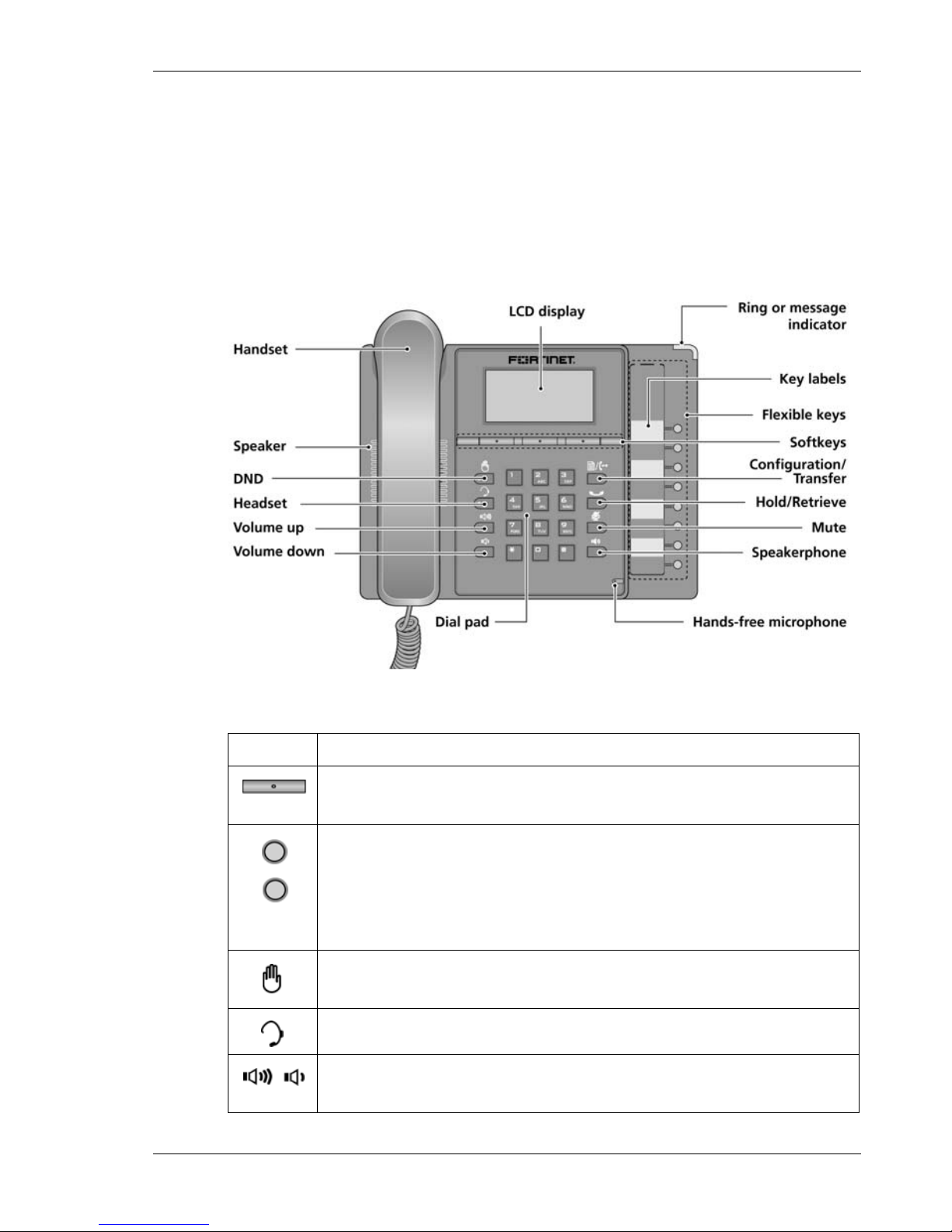
Figure 1: FON-350i Front
Item Function
Softkeys — Softkeys are interactive and change function
based on the state of the phone.
Flexible keys — Multi-colored LED keys that can be assigned
to engage and monitor lines, extensions or queues. They can
also be programmed as function and speed dial keys. Keys 1
and 2 are reserved for primary and secondary line appearance
for the extension. Keys 3–8 are programmable.
DND (Do Not Disturb) — Use to toggle on/off the DND feature
of the phone system.
Headset — Toggles the headset on and off-hook.
Volume control — Use to adjust ring, headset, handset, and
speaker volume.
Introduction Flexible Key States
FON-350i Telephone Start Guide v2 3
Flexible Key States
The flexible keys access lines, extensions and features based on the IP
phone configuration. Flexible keys assigned for line, extension or queue
appearances will monitor the state of those resources and allow access to
those resources at anytime unless the call is engaged by another user or the
system. Keys designated to monitor lines, extensions or queues indicate call
status as indicated below.
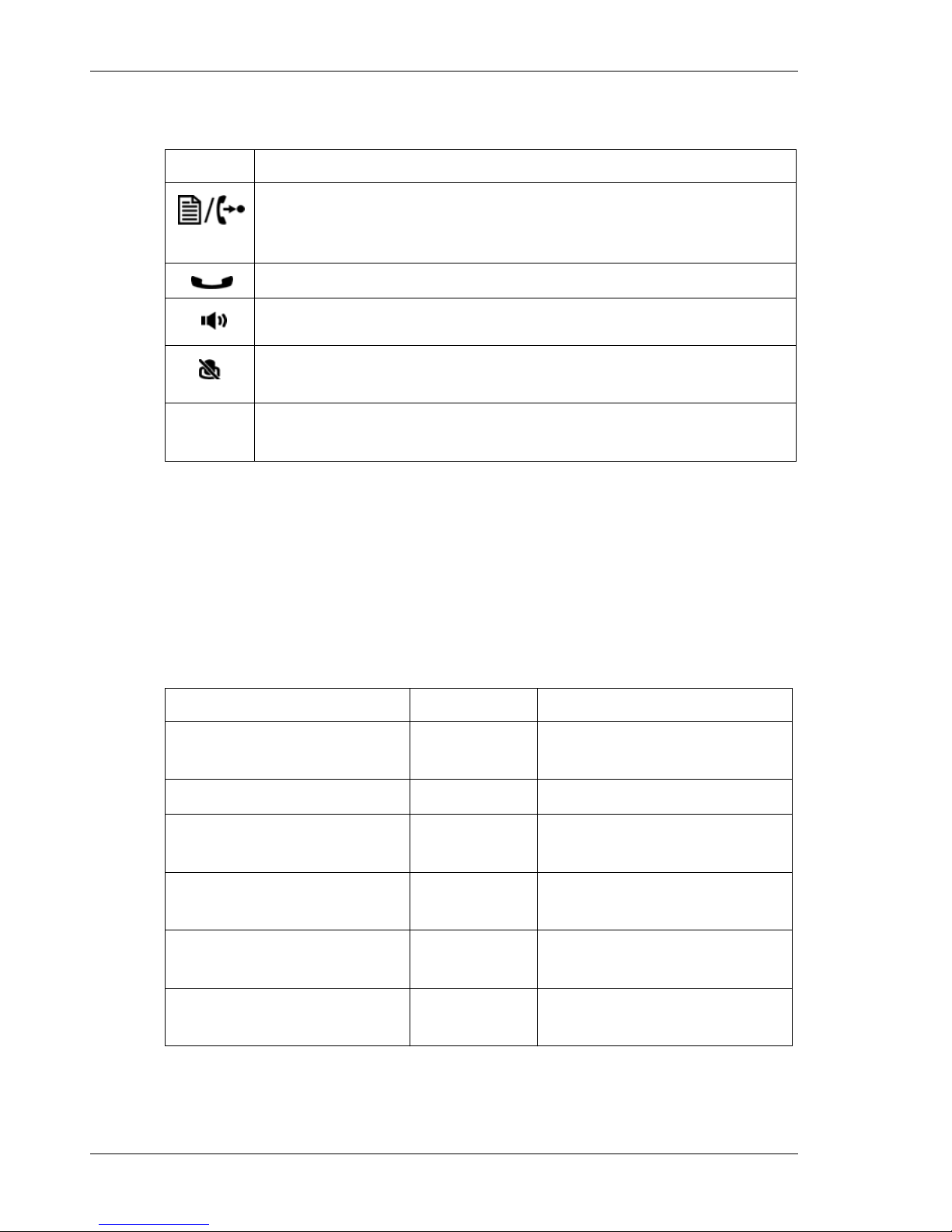
Configuration/Transfer — Use to transfer an active call. When
the phone is not in use, pressing this button accesses the menu
for making changes to the IP phone configuration.
Hold/Retrieve — Use to place or retrieve a call on hold.
Mute — Use to mute and unmute the microphone during calls.
Speakerphone — Press to engage the speakerphone and to
hang up after the call.
Dialpad — Use to dial a number, select a menu item, or input
a value.
Item Function
Status LED Color LED Pattern
Incoming call Green Flashing approx. once
every 1/2 second
Line in use on this phone Green On solid
Call on hold at extension Green Flashing approx. once
every second
Line/Extension/Queue
ringing
Green Flashing approx. once
every 1/2 second
Line/Extension/Queue
in use
Red On solid
Line/Extension/Queue
on hold
Red Flashing approx. once
every second
LCD Layout Introduction
4 FON-350i Telephone Start Guide v2
Flexible keys not assigned for line access may access features such as
Speed dial, Intercom, Park and others.
LCD Layout
The FON-350i phone has a 140x48 dot graphic LCD arranged to show 5 lines
of text and is used to display information to the user. The top-bar status line
displays icons, date and time. The bottom line shows choices associated with
the three context-sensitive softkeys located just below the LCD.
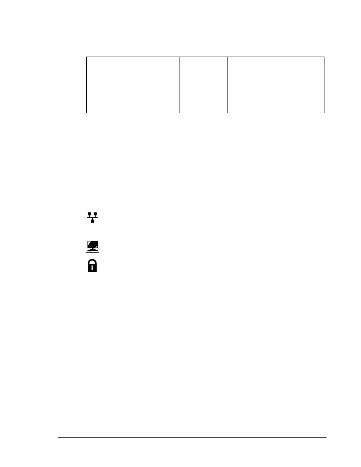
Below is a list of icons and their meaning.
LAN or Network connection icon, indicates the status of the LAN
connection to the IP phone. If the icon is blinking, check the LAN
connection.
PC port icon, when displayed, indicates a device such as a PC is
connected to the PC port of the IP phone.
Locked icon, indicates the IP phone is locked and a password is
required to place calls.
Extension/Line not
registered
Red/Yellow Alternating Red and Yellow
Do Not Disturb (DND)
enabled
Yellow On solid
Status LED Color LED Pattern
FON-350i Telephone Start Guide
FON-350i Telephone Start Guide v2 5
Installing the FON-350i
Connecting the IP Phone
The figure below shows the cable connections for your IP phone. The LAN
and desktop PC connections employ standard Category 5 cables
terminated with RJ-45 connectors. The FON-350i supports PoE (Power over
Ethernet) in accordance with the IEEE-802.1af Class 2 standard. When
connected to a PoE compliant LAN port, the IP Phone derives power from
the port. If the LAN port does not support PoE, use the AC/DC adaptor. The
handset connects to the base with the coiled handset cord.
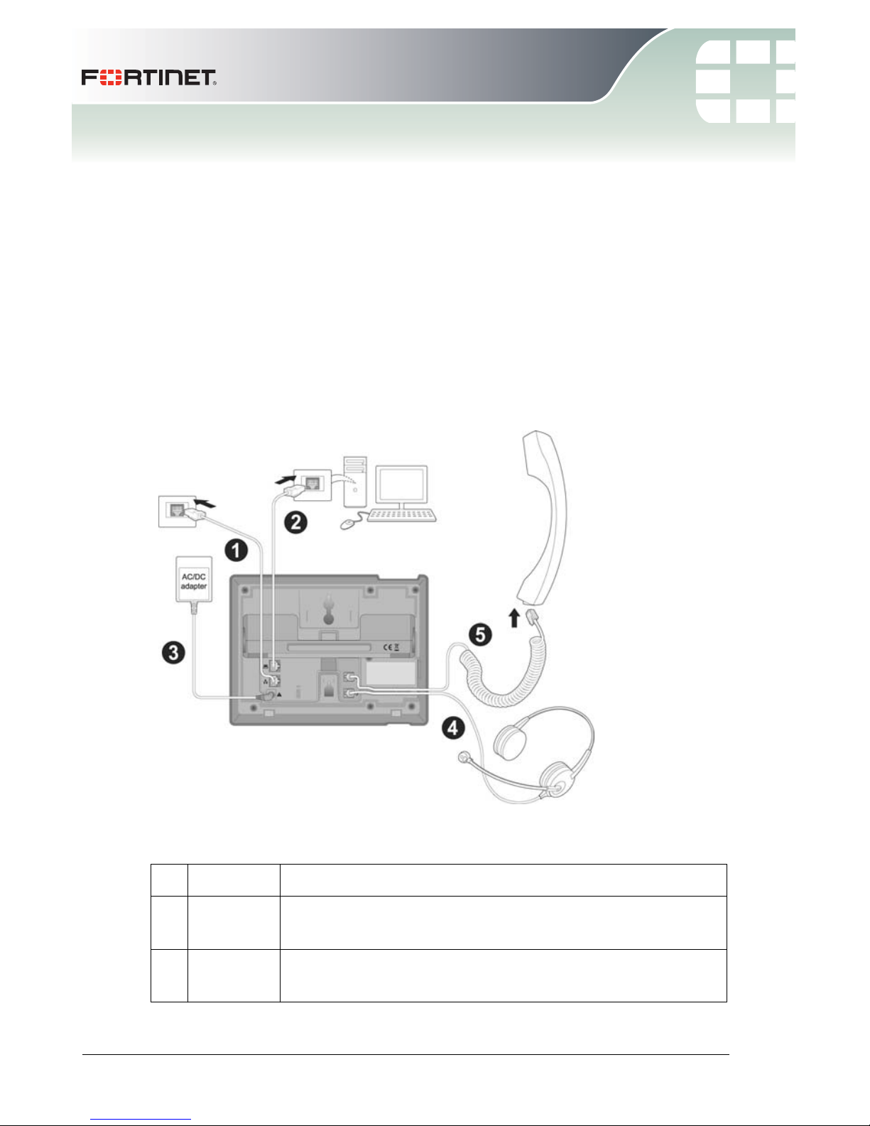
Figure 2: IP Phone Connections
Wiring Chart
1 LAN Connect the IP phone LAN port to the LAN wall jack with
the provided Ethernet cable.
2PC Optionally connect the IP phone PC port to your
desktop PC with an Ethernet cable (not supplied).
Attaching the Stand Installing the FON-350i
6 FON-350i Telephone Start Guide v2
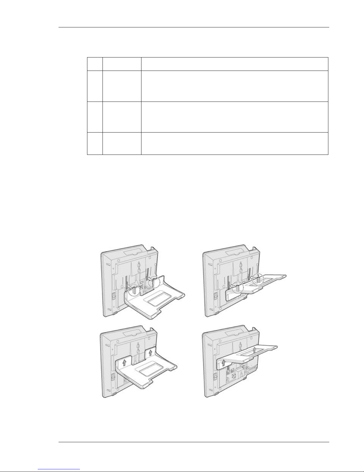
Attaching the Stand
The angle of the phone is set by the attachment of the provided stand in one
of two positions (30° or 55°).
To attach the stand,
1 Choose the desired angle for the phone.
2 Align the tabs on the stand with the notches in the base of the phone.
3 Push the stand upward in the slot as far as it can go until properly attached.
55° angle 30° angle
Figure 3: Installing the Foot Stand
3 Power If the LAN port supports PoE then the power adapter is
not required. If PoE is not supported on the LAN, connect
the power adapter to the power jack on phone.
4 Headset Optionally connect a headset to the RJ22 headset jack
on the phone. We strongly recommend the use of an
amplified headset.
5 Handset Connect the handset cord to the handset and the
handset jack on the phone.
Wiring Chart
 Loading...