

Page 1
FIM-7904E Interface Module Guide
7000
Page 2

FORTINET DOCUMENTLIBRARY
http://docs.fortinet.com
FORTINETVIDEOGUIDE
http://video.fortinet.com
FORTINETBLOG
https://blog.fortinet.com
CUSTOMERSERVICE&SUPPORT
https://support.fortinet.com
http://cookbook.fortinet.com/how-to-work-with-fortinet-support/
FORTIGATECOOKBOOK
http://cookbook.fortinet.com
FORTINETTRAININGSERVICES
http://www.fortinet.com/training
FORTIGUARDCENTER
http://www.fortiguard.com
FORTICAST
http://forticast.fortinet.com
ENDUSER LICENSE AGREEMENT
http://www.fortinet.com/doc/legal/EULA.pdf
FEEDBACK
Email: techdocs@fortinet.com
Friday, June 23, 2017
FIM-7904E Interface Module Guide
01-540-374567-20170623
Page 3

TABLEOFCONTENTS
FIM-7904E interface module 4
Physical Description 5
Front panel LEDs 5
Front panel connectors 6
Supported transceivers and breakout cables 7
Splitting the FIM-7904E B1 to B8 interfaces 7
Turning the module on and off 8
NMI switch 8
FIM-7904E hardware architecture 8
Hardware installation 10
Installing QSFP+, SFP+, and SFP transceivers 10
To install transceivers 10
FIM-7904E mounting components 11
Inserting a FIM-7904E module into a chassis 12
Shutting down and removing a FIM-7904E board from a chassis 16
Troubleshooting 18
FIM-7904E does not startup 19
FIM-7904E status LED is flashing during system operation 19
Quick FIM-7904E configuration 20
Registering your FortiGate-7000 series products 20
Choosing the configuration tool 20
Changing network settings 20
Cautions and Warnings 22
Environmental Specifications 22
Safety 23
Regulatory Notices 25
Federal Communication Commission (FCC) – USA 25
Industry Canada Equipment Standard for Digital Equipment (ICES) – Canada 25
European Conformity (CE) - EU 25
Voluntary Control Council for Interference (VCCI) – Japan 26
Product Safety Electrical Appliance & Material (PSE) – Japan 26
Bureau of Standards Metrology and Inspection (BSMI) – Taiwan 26
China 26
Page 4

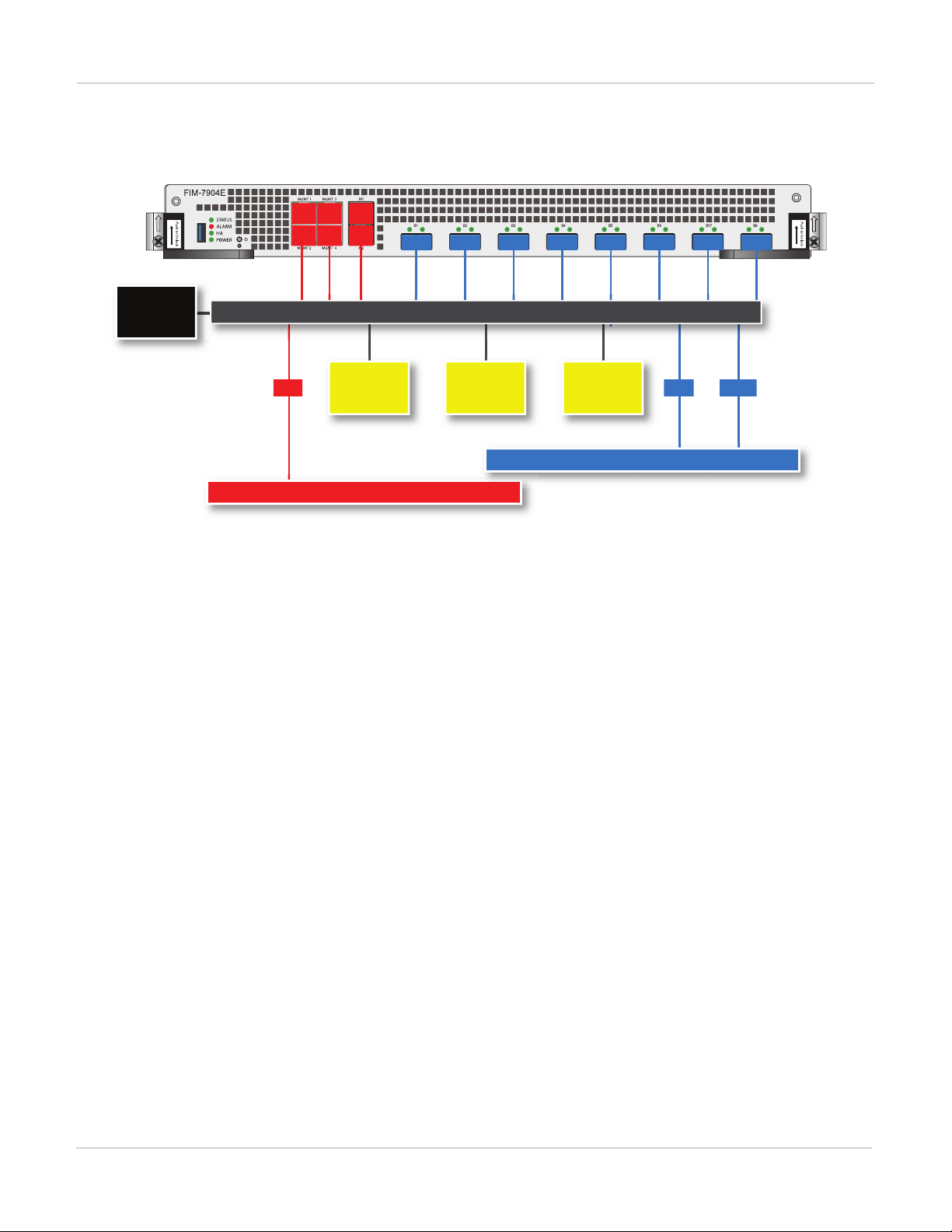
FIM-7904E interface module
Sliding
Latch
Handle
Retention
Screw
Handle
Sliding
Latch
Retention
Screw
B1 to B8
40GigE Fabric Channel
QSFP Network
Interfaces (data)
M1 and M2 10GigE Base
Channel SFP+ Interfaces
(heartbeat and management)
MGMT1 - MGMT4
10/100/1000BASE-T Copper
Management Interface
Status, Alarm
HA a nd Power
LEDS
USB
Power
Button
NMI
Button
FIM-7904E interface module
The FIM-7904E interface module is a hot swappable module that provides data, management and session
sync/heartbeat interfaces, base backplane switching and fabric backplane session-aware load balancing for a
FortiGate-7000 series chassis. The FIM-7904E includes an integrated switch fabric and DP2 processors to load
balance millions of data sessions over the chassis fabric backplane to FPM processor modules.
The FIM-7904E can be installed in any FortiGate-7000 series chassis. Normally you would install two FIM-7904E
modules in chassis hub/switch slots 1 and 2. Two FIM-7904Es provide a total of eight Quad Small Form-factor
Pluggable plus (QSFP+) interfaces for a FortiGate-7000 chassis. Using a 40GBASE-SR10 multimode QSFP+
transceiver, each QSFP+ interface can also be split into four 10GBASE-SR interfaces.
You can also install FIM-7904Es in a second chassis and operate the chassis in HA mode with another set of
processor modules to provide chassis failover protection.
FIM-7904E front panel
The FIM-7904E includes the following hardware features:
l Eight front panel 40GigE QSFP+ fabric channel interfaces (B1 to B8). These interfaces are connected to 40Gbps
networks to distribute sessions to the FPM processor modules installed in chassis slots 3 and up. Using 40GBASESR10 multimode QSFP+ transceivers, each QSFP+ interface can also be split into four 10GBASE-SR interfaces.
These interfaces also support creating link aggregation groups (LAGs) that can include interfaces from both FIM7904Es.
l Two front panel 10GigE SFP+ interfaces (M1 and M2) that connect to the base backplane channel. These
interfaces are used for heartbeat, session sync, and management communication between FIM-7904Es in different
chassis. These interfaces can also be configured to operate as Gigabit Ethernet interfaces using SFP transceivers,
but should not normally be changed. If you use switches to connect these interfaces, the switch ports should be
able to accept packets with a maximum frame size of at least 1526. The M1 and M2 interfaces need to be on
different broadcast domains. If M1 and M2 are connected to the same switch, Q-in-Q must be enabled on the
switch.
l Four 10/100/10000BASE-T out of band management Ethernet interfaces (MGMT1 to MGMT4).
l One 80Gbps fabric backplane channel for traffic distribution with each FPM module installed in the same chassis as
the FIM-7904E.
4 FIM-7904E Interface Module Guide
Fortinet Technologies Inc.
Page 5

FIM-7904E interface module Physical Description
l One 1Gbps base backplane channel for base backplane with each FPM module installed in the same chassis as the
FIM-7904E.
l One 40Gbps fabric backplane channel for fabric backplane communication with the other FIM-7904E in the chassis.
l One 1Gbps base backplane channel for base backplane communication with the other FIM-7904E in the chassis.
l On-board DP2 processors and an integrated switch fabric to provide high-capacity session-aware load balancing.
l One front panel USB port.
l Power button.
l NMIswitch (for troubleshooting as recommended by Fortinet Support).
l Mounting hardware.
l LED status indicators.
Physical Description
Dimensions 1.2 x 11.34 x 14 in. (3.1 x 28.8 x 35.1 cm) (Height x Width x Depth)
Weight 7.2 lb. (3.23 kg)
Operating Temperature 32 to 104°F (0 to 40°C)
Storage Temperature -31 to 158°F (-35 to 70°C)
Relative Humidity 10% to 90% (Non-condensing)
Front panel LEDs
From the FIM-7904E font panel you can view the status of the module LEDs to verify that the module is
functioning normally.
LED State Description
Off The FIM-7904E is powered off.
STATUS
Green The FIM-7904E is powered on and operating normally.
Flashing
The FIM-7904E is starting up.
Green
Red Major alarm.
ALARM
Amber Minor alarm
Off No alarms
FIM-7904E Interface Module Guide
Fortinet Technologies Inc.
5
Page 6

Front panel connectors FIM-7904E interface module
LED State Description
Off The FIM-7904E is operating in normal mode.
HA
POWER
B1 to B8
M1 and M2
Green The FIM-7904E is operating in HA mode.
Red A failover has occurred
Green The FIM-7904E is powered on and operating normally.
Off The FIM-7904E is powered off.
Green The correct cable is connected to the interface and the connected equipment has
power and is connected at 40Gbps or 10Gbps. If the port is split the LED will light
as long as at least one of the 10 Gbps connections is active.
Flashing
Green
Off No link is established.
Green
Flashing
Green
40 Gbps or 10Gbps network activity at the interface.
The correct cable is connected to the interface and the connected equipment has
power.
Network activity at the interface.
Off No link is established.
MGMT1-4
Link/Act
MGMT1-4
Speed
Solid
Green
Blinking
Green
Off No Link
Green Connection at 1Gbps.
Amber Connection at 100Mbps.
Off Connection at 10Mbps.
Indicates this interface is connected with the correct cable and the attached
network device has power.
Indicates network traffic on this interface.
Front panel connectors
You connect the FIM-7904E to your 100Gbps networks using the C1 to C4 front panel CFP2 interfaces. The front
panel also includes M1 and M2 SFP+ interfaces for the base channel, four Ethernet management interfaces
6 FIM-7904E Interface Module Guide
Fortinet Technologies Inc.
Page 7

FIM-7904E interface module Supported transceivers and breakout cables
(MGMT1 to MGMT4), and a USB port. The USB port can be used with any USB key for backing up and restoring
configuration files.
Connector Type Speed Protocol Description
USB USB 3.0
Type A
B1 to B8 QSFP+ 40Gbps/10Gbps Ethernet 40GbE connections using 40GBASE-SR/LR
M1 and M2 SFP+ 10Gbps/1Gbps Ethernet 10GbE connection (using SFP transceiver). For
MGMT1 to
MGMT4
RJ-45 10/100/1000Mbps Ethernet 10/100/1000BASE-T copper connection for
USB 3.0
USB 2.0
Standard USB connector.
Transceivers or 4x10GbE connections using
breakout cables.
heartbeat and synchronization between
chassis. 1GbE not recommended.
management or system administration.
Supported transceivers and breakout cables
Transceivers available from Fortinet for the FIM-7904E B1 to B8 QSFP+ interfaces.
Transceiver Description
FG-TRAN-QSFP+SR 40GE QSFP+ transceivers, short range.
FG-TRAN-QSFP+LR 40GE QSFP+ transceivers, long range.
Breakout cables available from Fortinet for the FIM-7904E B1 to B8 QSFP+ interfaces.
Breakout Description
FG-TRAN-QSFP-4XSFP 40GE QSFP+ Parallel Breakout Active Optical Cable with 1m length.
FG-TRAN-QSFP-4SFP-5 40GE QSFP+ Parallel Breakout MPO to 4x LC connectors, 5m reach.
Splitting the FIM-7904E B1 to B8 interfaces
Each 40GE interface (B1 to B8) on the FIM-7904Es in slot 1 and slot 2 of a FortiGate-7000 system can be split
into 4x10GBE interfaces. You split these interfaces after the FIM-7904Es are installed in your FortiGate-7000
system and the system us up and running. You can split the interfaces of the FIM-7904Es in slot 1 and slot 2 at
the same time by entering a single CLI command. Splitting the interfaces requires a system reboot so Fortinet
recommends that you split multiple interfaces at the same time according to your requirements to avoid traffic
disruption.
FIM-7904E Interface Module Guide
Fortinet Technologies Inc.
7
Page 8

Turning the module on and off FIM-7904E interface module
For example, to split the B1 interface of the FIM-7904E in slot 1 (this interface is named 1-B1) and the B1 and B4
interfaces of the FIM-7904E in slot 2 (these interfaces are named 2-B1 and 2-B4) connect to the CLI of your
FortiGate-7000 system using the management IP and enter the following command:
config system global
set split-port 1-B1 2-B1 2-B4
end
After you enter the command, the FortiGate-7000 reboots and when it comes up:
l The 1-B1 interface will no longer be available. Instead the 1-B1/1, 1-B1/2, 1-B1/3, and 1-B1/4 interfaces will be
available.
l The 2-B1 interface will no longer be available. Instead the 2-B1/1, 2-B1/2, 2-B1/3, and 2-B1/4 interfaces will be
available.
l The 2-B4 interface will no longer be available. Instead the 2-B4/1, 2-B4/2, 2-B4/3, and 2-B4/4 interfaces will be
available.
You can now connect breakout cables to these interfaces and configure traffic between them just like any other
FortiGate interface.
Turning the module on and off
You can use the front panel power button to turn the module power on or off. If the module is powered on, press
the power switch to turn it off. If the module is turned off and installed in a chassis slot, press the power button to
turn it on.
NMI switch
When working with Fortinet Support to troubleshoot problems with the FIM-7904E you can use the front panel
non-maskable interrupt (NMI) switch to assist with troubleshooting. Pressing this switch causes the software to
dump registers/backtraces to the console. After the data is dumped the board reboots. While the board is
rebooting, traffic is temporarily blocked. The board should restart normally and traffic can resume once its up and
running.
FIM-7904E hardware architecture
The FIM-7904E includes an integrated switch fabric (ISF) that connects the front panel interfaces to the DP2
session-aware load balancers and to the chassis backplanes. The ISFalso allows the DP2 processors to
distribute sessions amoung all NP6 processors on the FPMmodules in the same chassis.
8 FIM-7904E Interface Module Guide
Fortinet Technologies Inc.
Page 9
FIM-7904E interface module FIM-7904E hardware architecture
Chassis Base Backplane
Chassis Fabric Backplane
CPU
Integrated Switch Fabric
Management
(MGMT1-4)
Heartbeat
(M1 M2)
Data
(B1 - B8)
DP2 DP2 DP2
1G
80G
40G
FIM-7904E hardware architecture
FIM-7904E Interface Module Guide
Fortinet Technologies Inc.
9
Page 10

Installing QSFP+, SFP+, and SFP transceivers Hardware installation
Hardware installation
This chapter describes installing a FIM-7904E interface module into a FortiGate-7000 chassis.
Installing QSFP+, SFP+, and SFP transceivers
You must install QSFP+ transceivers into the FIM-7904E B1 to B8 interfaces before connecting them to 40Gbps
networks. See FIM-7904E front panel on page 4 for the locations of the B1 to B8 interfaces. You can install the
QSFP+ transceivers before or after inserting the FIM-7904E module into a chassis.
You must install SFP+ transceivers into the FIM-7904E M1 and M2 interfaces before connecting them to 10Gbps
networks. The FIM-7904E ships with two 10GBASE-SR SFP+ transceivers. You can also configure the M1 and
M2 interfaces to operate at 1Gbps and install SFP transceivers. You can install these transceivers before or after
inserting the FIM-7904E board into a chassis.
You can install the following types of transceivers for connectors M1 and M2:
l 10GBASE-SR SFP+ (10Gbps)
l 10GBASE-LR SFP+ (10Gbps)
l 1000BASE SFP (1Gbps)
The M1 and M2 interfaces are used for heartbeat, session sync, and management
communication between FIM-7904Es in different chassis. This communication
requires 10 Gbps connections so, even though it supported, the M1 and M2 interfaces
should not changed to 1000Base SFP 1Gbps interfaces.
To install transceivers
To complete this procedure, you need:
l A FIM-7904E
l Transceivers to install
l An electrostatic discharge (ESD) preventive wrist strap with connection cord
FIM-7904Es must be protected from static discharge and physical shock. Only handle
or work with FIM-7904Es at a static-free workstation. Always wear a grounded
electrostatic discharge (ESD) preventive wrist strap when handling FIM-7904Es.
Handling the transceivers by holding the release latch can damage the connector. Do
not force transceivers into their cage slots. If the transceiver does not easily slide in
and click into place, it may not be aligned correctly. If this happens, remove the
transceiver, realign it and slide it in again.
1.
Attach the ESD wrist strap to your wrist and to an available ESD socket or wrist strap terminal.
2.
Remove the caps from the cage sockets on the FIM-7904E front panel.
10 FIM-7904E Interface Module Guide
Fortinet Technologies Inc.
Page 11

Hardware installation FIM-7904E mounting components
Closed
Retention Screw
Handle
Latch
Latch
Alignment Pin
Handle
Retention Screw
Alignment Pin
Open
(when open the latch slides up about 2 mm)
3.
Hold the sides of the transceiver and slide it into the cage socket until it clicks into place.
FIM-7904E mounting components
To install a FIM-7904E you slide the module into a hub/switch slot in the front of an FortiGate-7000 series chassis
(either slot 1 or 2) and then use the mounting components to lock the module into place in the slot. When locked
into place and positioned correctly the module front panel is flush with the chassis front panel. The module is also
connected to the chassis backplane.
To position the module correctly you must use the mounting components shown below for the right of the FIM7904E front panel. The mounting components on the left of the front panel are the same but reversed. The FIM7904E mounting components align the module in the chassis slot and are used to insert and eject the module
from the slot.
On some FIM modules there may be very little clearance between the front panel
interfaces and the handle on the right side of the FIM-7904E. In fact you may have to
remove network connectors from some front panel interfaces to open the handle. In
most cases you should remove all network connectors from the front panel before
opening the handles to remove a FIM module from a chassis slot.
The FIM-7904E handles align the module in the chassis slot and are used to insert and eject the module from the
slot. The latches activate micro switches that turn on or turn off power to the module. When both latches are
raised the module cannot receive power. When the latches are fully closed if the module is fully inserted into a
chassis slot the module can receive power.
FIM-7904E Interface Module Guide
Fortinet Technologies Inc.
11
Page 12

Inserting a FIM-7904E module into a chassis Hardware installation
Inserting a FIM-7904E module into a chassis
This section describes how to install an FIM-7904E module into a FortiGate-7000 series chassis hub/switch slot
(slot 1 or 2).
You must carefully slide the module all the way into the chassis slot, close the handles
to seat the module into the slot, and tighten the retention screws to make sure the
module is fully engaged with the backplane and secured. You must also make sure
that the sliding latches are fully closed by gently pushing them down. The handles
must be closed, the retention screws tightened and the latches fully closed for the
module to get power and start up. If the module is not receiving power all LEDs remain
off.
FIM-7904Es are hot swappable. The procedure for inserting a FIM-7904E into a chassis slot is the same whether
or not the chassis is powered on.
To insert a FIM-7904E into a chassis slot
Do not carry the FIM-7904E by holding the handles or retention screws. When
inserting or removing the FIM-7904E from a chassis slot, handle the module by the
front panel. The handles are not designed for carrying the board. If the handles
become bent or damaged the FIM-7904E may not align correctly in the chassis slot.
To complete this procedure, you need:
l A FIM-7904E
l A FortiGate-7000 chassis with an empty hub/switch slot
l An electrostatic discharge (ESD) preventive wrist strap with connection cord
FIM-7904Es must be protected from static discharge and physical shock. Only handle
or work with FIM-7904Es at a static-free workstation. Always wear a grounded
electrostatic discharge (ESD) preventive wrist strap when handling FIM-7904Es.
Attach the ESD wrist strap to your wrist and to an ESD socket or to a bare metal
surface on the chassis or frame. (An ESD wrist strap is not visible in the photographs
below because they were taken in an ESD safe lab environment.)
12 FIM-7904E Interface Module Guide
Fortinet Technologies Inc.
Page 13

Hardware installation Inserting a FIM-7904E module into a chassis
1. Remove the FIM-7904E module from its packaging. Align the module with the chassis slot
and slide the module part way into the slot.
In the photograph an example FIM-7904E is being installed into chassis slot 1 of a FortiGate-7040E chassis.
2. Unlock the left and right handles by pushing the handle latches up about 2 mm until the
handles pop open.
Fully open both handles before sliding the module into the chassis to avoid damaging the handle mechanism.
Damaging the handles may prevent the module from connecting to power.
FIM-7904E Interface Module Guide
Fortinet Technologies Inc.
13
Page 14

Inserting a FIM-7904E module into a chassis Hardware installation
3. Carefully slide the module into the slot until the handles engage with the sides of the
chassis slot, partially closing them.
Insert the module by applying moderate force to the front faceplate (not the handles) to slide the module into the
slot. The module should glide smoothly into the chassis slot. If you encounter any resistance while sliding the
module in, the module could be aligned incorrectly. Pull the module back out and try inserting it again.
4. Push both handles closed and close the latches.
Closing the handles draws the module into place in the chassis slot and into full contact with the chassis
backplane. The module front panel should be in contact with the chassis front panel and the latches should drop
down and lock into place. You should gently push the latches down to make sure they lock. The module will not
receive power until the latches are fully locked.
14 FIM-7904E Interface Module Guide
Fortinet Technologies Inc.
Page 15

Hardware installation Inserting a FIM-7904E module into a chassis
5. Tighten both retention screws to secure the module in the chassis.
You can tighten the retention screws by hand with a Phillips screwdriver. If you use a power screwdriver the
tightening torque needs to be adjusted between 3 In-lb to 4 In-lb (0.4 N-m to 0.48 N-m).
As the latches are locked, power is supplied to the module. If the chassis is powered on during insertion the status
LED flashes green as the module starts up. Once the module has started up and is operating correctly, the front
panel LEDs are lit for normal operation.
Normal LED operation
LED State
Status Green
Alarm Off
HA Off
Power Green
FIM-7904E Interface Module Guide
Fortinet Technologies Inc.
15
Page 16

Shutting down and removing a FIM-7904E board from a chassis Hardware installation
Shutting down and removing a FIM-7904E board from a chassis
To avoid potential hardware problems, always shut down the FIM-7904E operating system properly before
removing the FIM-7904E from a chassis slot or before powering down the chassis.
Disconnect all cables from the FIM-7904E module, including all network cables and USB cables or keys.
FIM-7904Es are hot swappable. The procedure for removing a FIM-7904E from a chassis slot is the same
whether or not the chassis is powered on.
To remove a FIM-7904E board from a chassis slot
Do not carry the FIM-7904E by holding the handles or retention screws. When
inserting or removing the FIM-7904E from a chassis slot, handle the module by the
front panel. The handles are not designed for carrying the board. If the handles
become bent or damaged theFIM-7904E may not align correctly in the chassis slot.
To complete this procedure, you need:
l A FortiGate-7000 chassis with a FIM-7904E module installed
l An electrostatic discharge (ESD) preventive wrist strap with connection cord
FIM-7904Es must be protected from static discharge and physical shock. Only handle
or work with FIM-7904Es at a static-free workstation. Always wear a grounded
electrostatic discharge (ESD) preventive wrist strap when handling FIM-7904Es. (An
ESD wrist strap is not visible in the photographs below because they were taken in an
ESD safe lab environment.)
16 FIM-7904E Interface Module Guide
Fortinet Technologies Inc.
Page 17

Hardware installation Shutting down and removing a FIM-7904E board from a chassis
1. Fully loosen the retention screws.
You must fully loosen the screws or the handles may be damaged when used to eject the board from the chassis
slot.
2. Unlock the left and right handles by pushing the latches up about 2 mm until the handles
pop open.
Pushing the latches up turns off the module's power.
FIM-7904E Interface Module Guide
Fortinet Technologies Inc.
17
Page 18

Troubleshooting Hardware installation
3. Fully open the handles to eject the module from the chassis.
You need to open the handles with moderate force to eject the module from the chassis.
4. Hold the module front panel sides and slide it part way out of the slot. Then grasp the
module by the sides and carefully slide it out of the slot.
Troubleshooting
This section describes some common troubleshooting topics:
18 FIM-7904E Interface Module Guide
Fortinet Technologies Inc.
Page 19

Hardware installation Troubleshooting
FIM-7904E does not startup
Positioning of FIM-7904E mounting components and a few other causes may prevent a FIM-7904E from starting
up correctly.
Latches and handles not fully closed
If the latches or handles are damaged or positioned incorrectly the FIM-7904E may not start up. Make sure the
latches are fully closed and the handles are correctly aligned, fully inserted and locked and the retention screws
are tightened.
Firmware problem
If the FIM-7904E is receiving power and the latches are handles are fully closed, and you have restarted the
chassis and the FIM-7904E still does not start up, the problem could be with FortiOS. Connect to the FIM-7904E
console and try cycling the power to the board. If the BIOS starts up, interrupt the BIOS startup and install a new
firmware image.
If this does not solve the problem, contact Fortinet Technical Support.
FIM-7904E status LED is flashing during system operation
Normally, the FIM-7904E Status LED is off when the FIM-7904E is operating normally. If this LED starts flashing
while the module is operating, a fault condition may exist. At the same time the FIM-7904E may stop processing
traffic.
To resolve the problem you can try removing and reinserting the FIM-7904E in the chassis slot. Reloading the
firmware may also help.
If this does not solve the problem there may have been a hardware failure or other problem. Contact Fortinet
Technical Support for assistance.
FIM-7904E Interface Module Guide
Fortinet Technologies Inc.
19
Page 20

Registering your FortiGate-7000 series products Quick FIM-7904E configuration
Quick FIM-7904E configuration
This section is a quick start guide to connecting and configuring a FIM-7904E for your network.
Before using this chapter, your FortiGate chassis should be mounted and connected to your power system. In
addition, your FIM-7904Es should be inserted into the chassis in slots 1 or 2 and one or more processor modules
should be installed in chassis slots 3 and up. The chassis and the modules should also be powered up and the
front panel LEDs should indicate that the modules are functioning normally. As well the FIM-7904E and the
processor modules should be running the same FortiOS firmware version.
Registering your FortiGate-7000 series products
FortiGate-7000 series products are registered according to the chassis serial number. You need to register your
chassis to receive Fortinet customer services such as product updates and customer support. You must also
register your product for FortiGuard services. Register your product by visiting https://support.fortinet.com. To
register, enter your contact information and the serial numbers of the Fortinet products that you or your
organization have purchased.
Choosing the configuration tool
You can use either the GUI or the Command Line Interface (CLI) to configure the FIM-7904E. Some basic
configuration settings can only be done from the CLI. You can connect to the GUI using HTTP or HTTPS, You
can connect to the CLIusing SSH or Telent or by a direct console connection to the FIM-7904E Console port. Use
a terminal emulator with the following settings to connect to the console port: bits per second: 9600, data bits: 8,
parity: none, stop bits: 1, flow control: none.
Changing network settings
The FIM-7904E ships with the following factory default configuration.
Option Default Configuration
Administrator Account User
Name
Password (none)
MGMT1 to MGMT 4
IP/Netmask
admin
192.168.1.99/24
MGMT 1 to MGMT 4 of each FIM-7904E are configured as a static aggregate interface called mgmt and all have
the same IP address. If you have two FIM modules installed in your chassis, then MGMT 1 to MGMT 4 of both
modules are all in the same static aggregate interface.
20 FIM-7904E Interface Module Guide
Fortinet Technologies Inc.
Page 21

Quick FIM-7904E configuration Changing network settings
At any time during the configuration process, if you run into problems, you can reset the FIM-7904E to the factory
defaults and start over. From the CLI enter execute factoryreset.
Connect to the GUIby connecting MGMT1 of the module in slot 1 to your network and browsing to
https://192.168.1.99. Log into the GUI using the admin account with no password. Go to Network > Interface and
configure the FIM-7904E interfaces to connect to your network.
FIM-7904E Interface Module Guide
Fortinet Technologies Inc.
21
Page 22

Environmental Specifications Cautions and Warnings
Cautions and Warnings
Environmental Specifications
Rack Mount Instructions - The following or similar rack-mount instructions are included with the installation
instructions:
Instructions de montage en rack - Les instructions de montage en rack suivantes ou similaires sont incluses
avec les instructions d'installation:
Elevated Operating Ambient - If installed in a closed or multi-unit rack assembly, the operating ambient
temperature of the rack environment may be greater than room ambient. Therefore, consideration should be
given to installing the equipment in an environment compatible with the maximum ambient temperature (Tma)
specified by the manufacturer.
Température ambiante élevée – S'il est installé dans un rack fermé ou à unités multiples, la température
ambiante de fonctionnement de l'environnement du rack peut être supérieure à la température ambiante de la
pièce. Par conséquent, il est important d’installer le matériel dans un environnement respectant la température
ambiante maximale (Tma) stipulée par le fabricant.
Reduced Air Flow - Installation of the equipment in a rack should be such that the amount of air flow required
for safe operation of the equipment is not compromised.
Ventilation réduite – Installation de l'équipement dans un rack doit être telle que la quantité de flux d'air
nécessaire au bon fonctionnement de l'équipement n'est pas compromise.
Mechanical Loading - Mounting of the equipment in the rack should be such that a hazardous condition is not
achieved due to uneven mechanical loading.
Chargement Mécanique – Montage de l'équipement dans le rack doit être telle qu'une situation dangereuse
n'est pas lié à un chargement mécanique inégal.
Circuit Overloading - Consideration should be given to the connection of the equipment to the supply circuit
and the effect that overloading of the circuits might have on overcurrent protection and supply wiring. Appropriate
consideration of equipment nameplate ratings should be used when addressing this concern.
Surtension – Il convient de prendre l’ensemble des précautions nécessaires lors du branchement de
l’équipement au circuit d’alimentation et être particulièrement attentif aux effets de la suralimentation sur le
dispositif assurant une protection contre les courts-circuits et le câblage. Ainsi, il est recommandé de tenir
compte du numéro d’identification de l’équipement.
Reliable Earthing - Reliable earthing of rack-mounted equipment should be maintained. Particular attention
should be given to supply connections other than direct connections to the branch circuit (e.g. use of power
strips).
22 FIM-7904E Interface Module Guide
Fortinet Technologies Inc.
Page 23

Cautions and Warnings Safety
Fiabilité de la mise à la terre – Fiabilité de la mise à la terre de l'équipement monté en rack doit être
maintenue. Une attention particulière devrait être accordée aux connexions d'alimentation autres que les
connexions directes au circuit de dérivation (par exemple de l'utilisation de bandes de puissance).
Blade Carriers, Cards and Modems must be Listed Accessories or Switch, Processor, Carrier and similar blades or
cards should be UL Listed or Equivalent.
Serveur-blades, cartes et modems doivent être des accessoires listés ou commutateurs, processeurs, serveurs et
similaire blades ou cartes doivent être listé UL ou équivalent.
Refer to specific Product Model Data Sheet for Environmental Specifications (Operating Temperature, Storage
Temperature, Humidity, and Altitude).
Référez à la Fiche Technique de ce produit pour les caractéristiques environnementales (Température de
fonctionnement, température de stockage, humidité et l'altitude).
Safety
Moving parts — Hazardous moving parts. Keep away from moving fan blades.
Pièces mobiles – Pièces mobiles dangereuses. Se tenir éloigné des lames mobiles du ventilateur.
Warning: Equipment intended for installation in Restricted Access Location.
Avertissement: Le matériel est conçu pour être installé dans un endroit où l’accès est restreint.
Warning: A readily accessible disconnect device shall be incorporated in the building installation wiring.
Avertissement: Un dispositif de déconnexion facilement accessible doit être incorporé dans l'installation
électrique du bâtiment.
Battery – Risk of explosion if the battery is replaced by an incorrect type. Do not dispose of batteries in a fire.
They may explode. Dispose of used batteries according to your local regulations. IMPORTANT: Switzerland:
Annex 4.10 of SR814.013 applies to batteries.
Batterie – Risque d'explosion si la batterie est remplacée par un type incorrect. Ne jetez pas les batteries au feu.
Ils peuvent exploser. Jetez les piles usagées conformément aux réglementations locales. IMPORTANT: Suisse:
l'annexe 4.10 de SR814.013 s’appliquent aux batteries.
警告
本電 池 如果更 換 不正確 會 有爆炸 的 危險
請依 製 造商說 明 書處理 用 過之電 池
Caution: Disconnect power supply cords before servicing
Attention: Débranchez les cordons de la source d’alimentation avant tout entretien.
Grounding — To prevent damage to your equipment, connections that enter from outside the building should
pass through a lightning / surge protector, and be properly grounded. Use an electrostatic discharge workstation
FIM-7904E Interface Module Guide
Fortinet Technologies Inc.
23
Page 24

Safety Cautions and Warnings
(ESD) and/or wear an anti-static wrist strap while you work. In addition to the grounding terminal of the plug, on
the back panel, there is another, separate terminal for earthing.
Mise à la terre — Pour éviter d’endommager votre matériel, assurez-vous que les branchements qui entrent à
partir de l’extérieur du bâtiment passent par un parafoudre / parasurtenseur et sont correctement mis à la terre.
Utilisez un poste de travail de décharge électrostatique (ESD) et / ou portez un bracelet anti-statique lorsque vous
travaillez. Ce produit possède une borne de mise à la terre qui est prévu à l’arrière du produit, à ceci s’ajoute la
mise à la terre de la prise.
This product has a separate protective earthing terminal provided on the back of the product in addition to the
grounding terminal of the attachment plug. This separate protective earthing terminal must be permanently
connected to earth with a green with yellow stripe conductor minimum size # 6 AWG and the connection is to be
installed by a qualified service personnel.
Ce produit a une borne de mise à la terre séparé sur le dos de l'appareil, en plus de la borne de mise à la terre de
la fiche de raccordement. Cette borne de mise à la terre séparée doit être connecté en permanence à la terre
avec un conducteur vert avec la taille bande jaune de minimum # 6 AWG et la connexion doit être installé par un
personnel qualifié.
Caution: Slide/rail mounted equipment is not to be used as a shelf or a work space.
Attention: Un équipement monté sur bâti ne doit pas être utilisé sur une étagère ou dans un espace de travail.
Fiber optic transceiver must be rated 3.3V, 22mA max, Laser Class 1, UL certified component.
Le transceiver optique doit avoir les valeurs nominales de 3.3 V, maximum 22 mA, Laser Class 1, homologué UL.
Fiber optic transceiver must be rated 3.3V, 22mA max, Laser Class 1, UL certified component.
Le transceiver optique doit avoir les valeurs nominales de 3.3 V, maximum 22 mA, Laser Class 1, homologué UL
24 FIM-7904E Interface Module Guide
Fortinet Technologies Inc.
Page 25

Regulatory Notices Federal Communication Commission (FCC) – USA
Regulatory Notices
Federal Communication Commission (FCC) – USA
This device complies with Part 15 of FCC Rules. Operation is subject to the following two conditions:
(1) this device may not cause harmful interference, and
(2) this device must accept any interference received; including interference that may cause undesired operation.
This equipment has been tested and found to comply with the limits for a Class A digital device, pursuant to Part
15 of the FCC Rules. These limits are designed to provide reasonable protection against harmful interference
when the equipment is operated in a commercial environment. This equipment generates, uses, and can radiate
radio frequency energy, and if it is not installed and used in accordance with the instruction manual, it may cause
harmful interference to radio communications. Operation of this equipment in a residential area is likely to cause
harmful interference, in which case the user will be required to correct the interference at his own expense.
WARNING: Any changes or modifications to this product not expressly approved by the party responsible for
compliance could void the user’s authority to operate the equipment.
Industry Canada Equipment Standard for Digital Equipment (ICES) – Canada
CAN ICES-3 (A) / NMB-3 (A)
This digital apparatus does not exceed the Class A limits for radio noise emissions from digital apparatus set out
in the Radio Interference Regulations of the Canadian Department of Communications.
Cet appareil numérique n’émet pas de bruits radioélectriques dépassant les limites applicables aux appareils
numériques de la classe A prescrites dans le Règlement sur le brouillage radioélectrique édicte par le ministère
des Communications du Canada.
European Conformity (CE) - EU
This is a Class A product. In a domestic environment, this product may cause radio interference, in which case
the user may be required to take adequate measures.
FIM-7904E Interface Module Guide
Fortinet Technologies Inc.
25
Page 26

Voluntary Control Council for Interference (VCCI) – Japan Regulatory Notices
Voluntary Control Council for Interference (VCCI) – Japan
この装置 は、クラスA情 報 技術装 置 です。この装置を 家 庭環境 で使用 すると電波妨 害 を引 き起 こすことがありま
す。この場合 には使用 者が適切 な対策 を講ずるよう要求 されることがあります。VCCI-A
Product Safety Electrical Appliance & Material (PSE) – Japan
日本 では電気 用品安 全 法(PSE)の規 定 により、同梱 している電 源コードは本製 品の専用 電源コードとして利 用 し、
他の製品に使用 しないでください。
Bureau of Standards Metrology and Inspection (BSMI) – Taiwan
這是 甲 類的資 訊 產品,在 居 住的環 境 中使用 時 ,可能會 造 成射頻 干 擾,在這 種 情況 下 ,使用 者會被 要 求採
取某 些 適當的 對 策。
China
此为 A级 产 品,在生 活 环境中 ,该 产品可 能 会造成 无 线电干 扰 。这种情 况 下,可能 需 要用户 对 其采取 切 实
可行 的 措施。
26 FIM-7904E Interface Module Guide
Fortinet Technologies Inc.
Page 27

Copyright© 2017Fortinet, Inc. All rights reserved. Fortinet®, F ortiGate®, FortiCare® and FortiGuard®, and certain other marks are registered trademarks of Fortinet,
Inc., in t he U.S. and other jurisdictions, and other Fortinet names herein may also be registered and/or common law trademarks of Fortinet. All other product or company
names may be trademarks of their respective owners. Performance and other metrics contained herein were att ained in internal lab t ests under ideal c onditions, and
actual performance and other results may vary. Network variables, different network environments and other conditions may affect performance results. Nothing herein
represents any binding commitment by Fortinet, and Fortinet disclaims all warranties, whether express or implied, except to the extent Fortinet enters a binding written
contract, s igned by Fortinet’s General Counsel, with a purchaser that expressly warrants that the identified product will perform according to certain expressly-identified
performance metrics and, in such event, only the specific performance metrics expressly identified in such binding writ ten contract shall be binding on F ortinet. For
absolute c larity, any such warranty will be limited to performance in the same ideal c onditions as in Fortinet’s internal lab tests . In no event does Fortinet make any
commitment related to future deliverables, features, or development, and circumstances may change s uch that any f orward-looking statements herein are not accurate.
Fortinet disclaims in full any covenants, representations, and guarantees pursuant hereto, whether express or implied. Fortinet reserves the right to change, modify,
transfer, or otherwise revis e this publication without notice, and the most current version of t he publication shall be applicable.
 Loading...