

Page 1

IDD Flame Detector Heads
Standard Models: IDD-II, IDD-IIL, IDD-IIU, and IDD-Ultra
CEX Models: IDD-IICEX, IDD-IILCEX, IDD-IIUCEX
372000-05 Rev J
Page 2

IDD Flame Detector Heads Manual
Revision
Date
Comments
A
Initial Release
B
C
4/2003
D
6/2004
E
6/2004
F
10/2006
G
07/2013
Add CEX and Ultra versions of detector heads, update graphics.
H
08/2013
Correct graphics with cable support brackets.
J
09/2015
Update logo and address. Remove IDD-UV and IDD-UltraCEX
372000-05 Rev J
INTRODUCTION
This manual contains information for the IDD Flame Detector Heads from Forney Corporation, 16479 N.
Dallas Parkway, Suite 600, Addison, Texas.
All personnel should become thoroughly familiar with the contents of this manual before attempting to
install, operate or maintain the system. Because it is virtually impossible to cover every situation that might
occur during operation and maintenance of the equipment described in this publication, personnel are
expected to use good engineering judgment when confronted with situations that are not specifically
mentioned herein.
The user should update this manual whenever significant changes are made to the system. To be of value,
the manual must always reflect the latest configuration of the equipment. It should be noted, however, that
Forney Corporation will furnish updated pages only if Forney authorizes a modification and accomplished
under Forney supervision.
PROPRIETARY NOTICE
The contents of this publication are proprietary data of Forney Corporation. Reproduction or use of any
part of the publication for purposes other than the support of the equipment for which it is published is
permissible only if expressly authorized in writing by Forney.
Additional copies of this publication may be purchased from Forney. When ordering or requesting cost
information, refer to the publication number appearing on the title page. Address to the attention of the
Sales Department, Forney Corporation, 16479 N. Dallas Parkway, Suite 600, Addison, Texas 75001.
Revisions
i
Page 3

IDD Flame Detector Heads Manual
372000-05 Rev J
TABLE OF CONTENTS
Section 1 Description .................................................................................................................................. 3
Figure 1 Dimensional drawing – IDD Standard housing ................................................................. 3
1.1 IDD CEX ......................................................................................................................................... 4
Figure 2 Dimensional drawing – IDD CEX..................................................................................... 4
1.2 Mechanical Specifications ............................................................................................................... 5
1.3 Safety ............................................................................................................................................... 6
Section 2 Installation ................................................................................................................................... 7
2.1 Installation Procedure ...................................................................................................................... 7
2.1.1 IDD-CEX Mounting Flange ............................................................................................... 8
Figure 3 Detector Sighting ............................................................................................................... 8
Figure 4 Detector Location VS. Secondary air rotation ................................................................... 9
Figure 5 IDD Direct Mount Arrangement ..................................................................................... 10
Figure 6 IDD Swivel Mount Arrangement .................................................................................... 11
Figure 7 IDD Direct Mount with Cooling Chamber ...................................................................... 11
Figure 8 IDD Swivel Mount Arrangement with Cooling Chamber ............................................... 11
Figure 9 IDD-CEX Direct Mount Arrangement ........................................................................... 12
Figure 10 IDD-CEX Swivel Mount Arrangement ......................................................................... 12
Figure 11 IDD-CEX Direct Mount Arrangement with Cooling Chamber .................................... 13
Figure 12 IDD-CEX Swivel Mount Arrangement with Cooling Chamber ................................... 13
2.2 Detector Wiring ............................................................................................................................. 14
Figure 13 Sample Wiring Diagram for IDD Detector Head to Amplifier .................................... 14
Section 3 Commissioning .......................................................................................................................... 14
3.1 Checkout Procedure ....................................................................................................................... 14
3.1.1 Initial Checkout ................................................................................................................. 14
3.1.2 Operational Checkout ....................................................................................................... 14
Section 4 Operation ................................................................................................................................... 15
Section 5 Troubleshooting ........................................................................................................................ 15
TABLE 1: IDD Detector Head Troubleshooting .......................................................................... 15
Section 6 Maintenance .............................................................................................................................. 16
Section 7 Storage ....................................................................................................................................... 16
Section 8 Return or Repair Service ......................................................................................................... 16
Section 9 Parts ........................................................................................................................................... 17
TABLE 2: IDD Detector Head Assembly Parts ........................................................................... 17
ii
Page 4
IDD Flame Detector Heads Manual
Detector Head
Typical Application
Spectral Response
Sensor
Housing
IDD-II
Oil and Coal
IR 700 to 3300 nm
Lead sulfide
Standard
IDD-IICEX
Oil and Coal
IR 700 to 3300 nm
Lead sulfide
CEX
IDD-IIL
Lignite
IR 700 to 3300 nm
Lead sulfide
Standard
IDD-IILCEX
Lignite
IR 700 to 3300 nm
Lead sulfide
CEX
IDD-IIU
Unfiltered for Oil &
Coal
IR 400 to 3300 nm
Lead sulfide
Standard
IDD-IIUCEX
Unfiltered for Oil &
Coal
IR 400 to 3300 nm
Lead sulfide
CEX
IDD-Ultra
Natural Gas
UV 200 to 425 nm
Silicon carbide
Standard
372000-05 Rev J
Section 1 Description
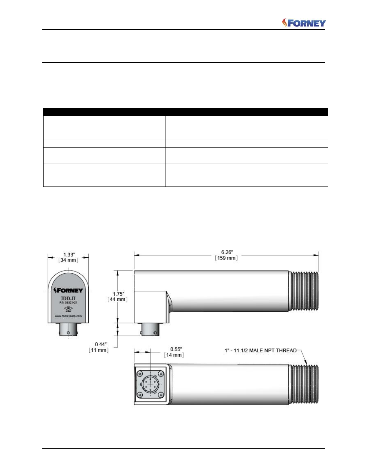
The Forney IDD flame detector heads are non-repairable devices that generate an AC signal of variable
amplitude and frequency proportional to a burner’s flame intensity. The detector head transmits the signal
through a four-conductor cable to an applicable Forney flame amplifier.
The IDD family of products offers a range of flame detector heads for a variety of fuels / applications.
The major components of the IDD flame detector heads are a metal housing containing a photocell and a
printed circuit board that provides power and amplifies the cell’s output signal. The IR series of detector
heads (-II, -IIU, -IIL, -IICEX, -IIUCEX, -IILCEX) contain a lead sulfide photocell and the UV detector–
ULTRA) heads utilize a silicon carbide cell. The complete assembly is potted with non-repairable epoxy.
Figure 1 Dimensional drawing – IDD Standard housing
Approvals: Factory Mutual
3
Page 5
IDD Flame Detector Heads Manual
372000-05 Rev J
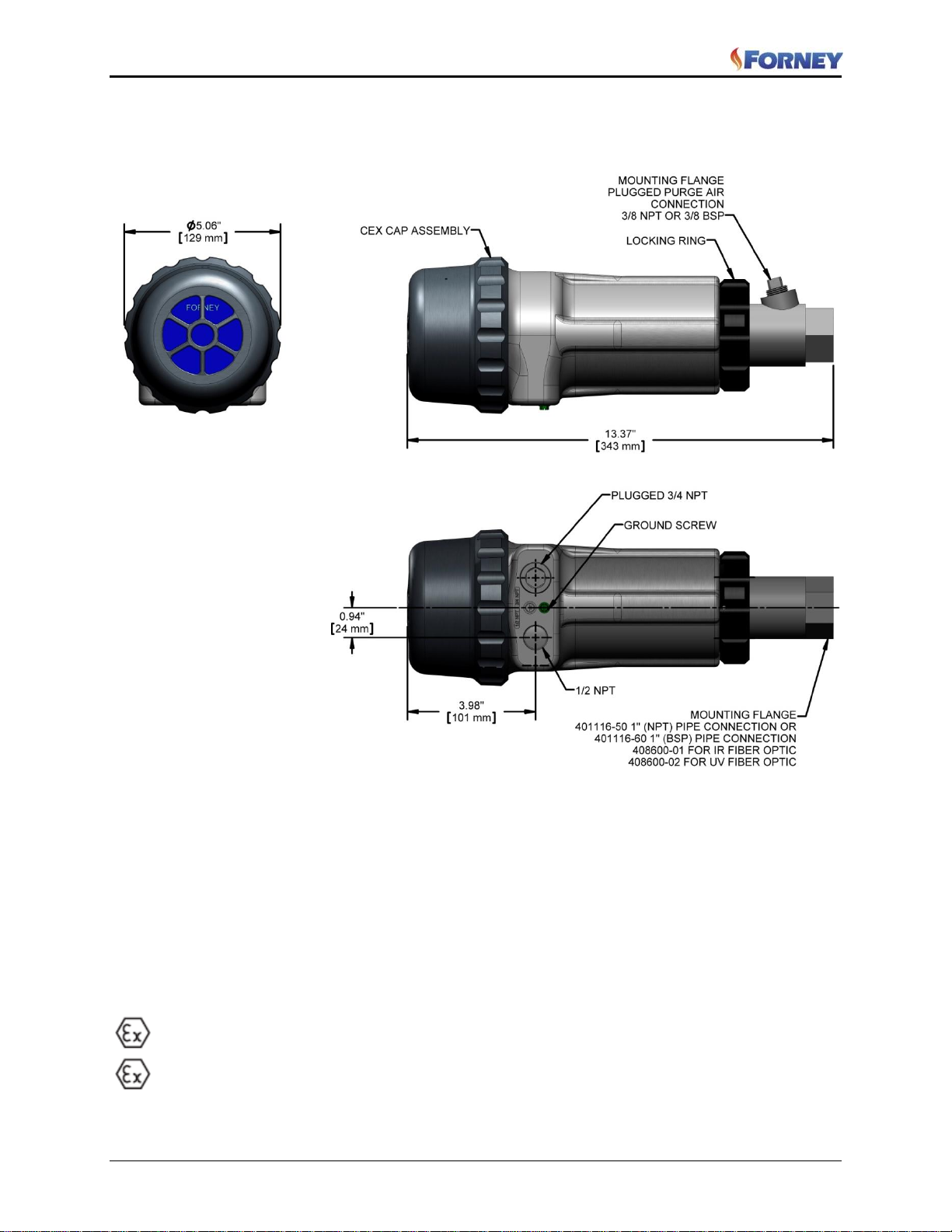
1.1 IDD CEX
Figure 2 Dimensional drawing – IDD CEX
Housing Material: Aluminum Alloy, A 380
Window joints are cemented using Aremco bond 568 high temperature epoxy with a temperature
index of -204C
Window material is fused silica with a temperature index of 950C
O-rings are made of BUNA-N with a thermal index of +121C
Suitably rated blanking elements must be used on all unused openings
Supply connection wiring shall have a temperature rating of at least 105°C
Approvals: Factory Mutual
ATEX Certification number FM10ATEX0024
II 2 G Ex d IIC T6 IP66
II 2 D Ex tD A21 IP66 T85°C
4
Page 6

IDD Flame Detector Heads Manual
ATTRIBUTE
STANDARD MODELS
ATEX MODELS
Models
IDD-II, IDD-IIL, IDD-IIU,
IDD-Ultra
IDD-IICEX, IDD-IILCEX,
IDD-IIUCEX
Approvals
Factory Mutual (FM)
Factory Mutual (FM)
Housing Rating
NEMA4
NEMA4
II 2 G Ex d IIC T6 IP66
II 2 D Ex tD A21 IP66 T85oC
MECHANICAL
Size
1.75 x 6.25 inches
(44.5 x 158.8 mm)
5.75 x 13.37 inches
(146.1 x 339.6 mm)
Weight
1.3 lbs (0.59kg)
7.1 lbs (3.23kg)
Mounting
1.0 inch NPT male pipe
1.0 inch NPT female pipe mount
1.0 inch BSP female pipe mount
Viewing Angle (non-restricted)
120 degrees
90 degrees
Recommended Viewing Angle
3 to 5 degrees
3 to 5 degrees
Temperature Rating
Operating:
IDD-II, IDD-IIL and IDD-IIU
32oF to 140oF (0oC to 60oC)
IDD-Ultra
32oF to 250oF (0oC to 121oC)
Storage:
-25oF to 140oF (-32oC to 60oC)
Operating:
IDD-II, IDD-IIL and IDD-IIU
32oF to 140oF (0oC to 60oC)
Storage:
-25oF to 140oF (-32oC to 60oC)
Cooling / Sealing Air
Front Mount:
10 scfm @ 6-inches w.c.
(16m3/hr @ 152Kg/m2)
Fiber Optic:
15 scfm @ 6-inches w.c.
(25m3/hr @ 152Kg/m2)
Front Mount:
10 scfm @ 6-inches w.c.
(16m3/hr @ 152Kg/m2)
Fiber Optic:
15 scfm @ 6-inches w.c.
(25m3/hr @ 152Kg/m2)
Maximum Cooling Air Temp
IDD-II, IDD-IIL and IDD-IIU
120oF (49oC)
IDD-Ultra
170oF (77oC)
IDD-II, IDD-IIL and IDD-IIU
120oF (49oC)
ELECTRICAL
Input Voltage
+50Vdc for cell bias
+12 to +15Vdc logic
+50Vdc for cell bias
+15Vdc logic
Output Voltage
0.1 to 0.8 Vac peak to peak
0.1 to 0.8 Vac peak to peak
Power Consumption
0.12 VA maximum
0.22 VA maximum
Cable Rating
4 conductor, shielded, 20-gauge
stranded wire
4-conductor, shielded, 20-gauge,
stranded wire
Maximum Cable Length
1320 feet (402.3 meters)
1320 feet (402.3 meters)
Connector
MS3112E10-6P
Internal 4-position terminal
block
372000-05 Rev J
1.2 Mechanical Specifications
5
Page 7
IDD Flame Detector Heads Manual
372000-05 Rev J
1.3 Safety
The IDD model flame detector heads’ voltage point is not accessible under normal operating conditions.
However, users should follow appropriate electrical safety procedure when installing the flame detector.
Electrical power should always be removed from the flame detector amplifier before installing or
replacing a flame detector head assembly. In addition, if a flame detector head must be replaced while the
furnace is in operation, maintenance personnel should exercise caution to avoid exposure to flying
particles and hot furnace gas.
WARNING:
Do Not Open When Energized
WARNING:
When installing and/or removing the IDD model flame detectors, wear safety glasses to prevent eye injury
caused by airborne particles in cooling/seal-air supply or wind box.
CAUTION: The detector head contains sensitive electrical components. Ensure that all power is removed
from the external amplifier assembly before connecting or disconnecting the I/O cable.
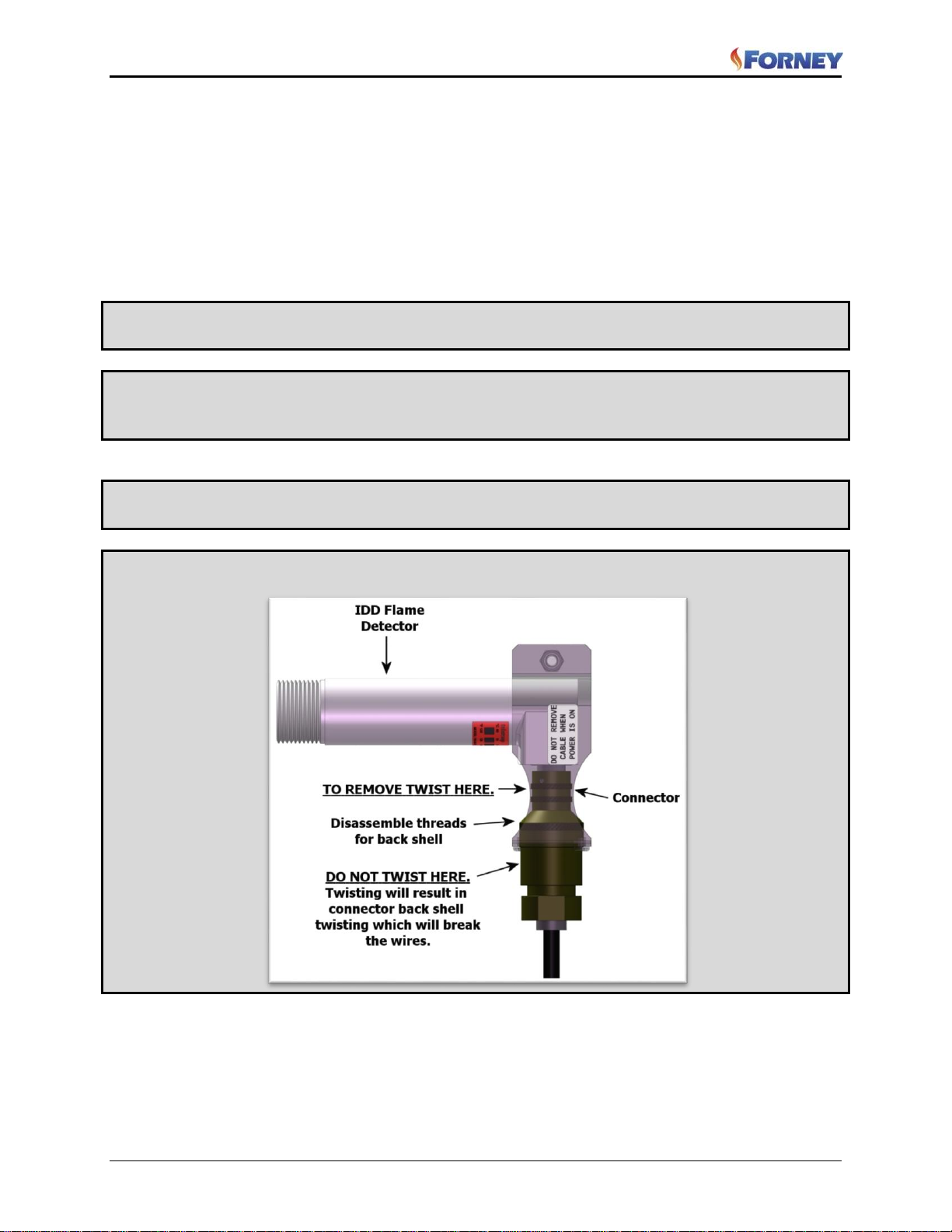
CAUTION: Disconnect the cable from the detector by hand, but do NOT twist the connector barrel.
Twisting could cause the wires to become disconnected from solder connections inside the connector barrel.
6
Page 8

IDD Flame Detector Heads Manual
372000-05 Rev J
Section 2 Installation
The IDD flame detectors determine the presence or absence of flame by monitoring the amplitude of the
flame across a flicker frequency spectrum. The detector should initially be mounted so that the primary
combustion zone is within the detector’s line of sight.
The IDD detectors are usually located on the boiler in a position that minimizes radiant or conducted heat
to the detector. In some cases, supplementary cooling chambers may be required. Typical installations
will have either a single union ball valve (front mount) or a “Quick Disconnect” Hansen-type fitting (fiberoptic) for ease of maintenance and a support bracket for the four-conductor cable. Cable support brackets
are not used with supplemental cooling chambers or CEX versions.
Two typical IDD detector installations are “front mount” or direct-view sighting and fiber-optic sighting
used when direct-view sighting is difficult. The detectors systems are shipped with appropriate mounting
equipment from Forney Corporation.
NOTE:
For fiber optic installations refer to Forney Publication 372000-73, Fiber Optic Installations manual.
The location and sighting instructions listed in the following sections are general guidelines for the location
of the detector. Consult Forney for application specific guidance on installation. The detector provides
feedback to a Forney Flame Amplifier which goes onto the burner management system (BMS).
NOTE:
An acceptable detector location must ensure:
Reliable main flame and/or igniter flame detection at all air flow and furnace loads (ranges of fuel
firing).
Rejection of the igniter flame if too short or in the wrong position to ignite the main flame reliably.
When installing a detector head for the first time, ensure the following requirements are satisfied:
The physical mounts are adequate to support the weight of the detector head in the position required
for operation.
The ball valve lever of the cooling-air line moves through its entire operating range without obstruction
from any structure, cable, or hose.
The cooling-air hose and I/O cable do not interfere with the operation of any moving components at
the boiler front. The I/O cable does not contact hot surfaces capable of melting its insulation.
The cable must not run close to any cable or equipment carrying high voltage to keep interference to
minimum.
2.1 Installation Procedure
WARNING: Protective filtered lenses should be worn when viewing flame; infrared and ultraviolet energy
from the flame can be damaging to the eyes.
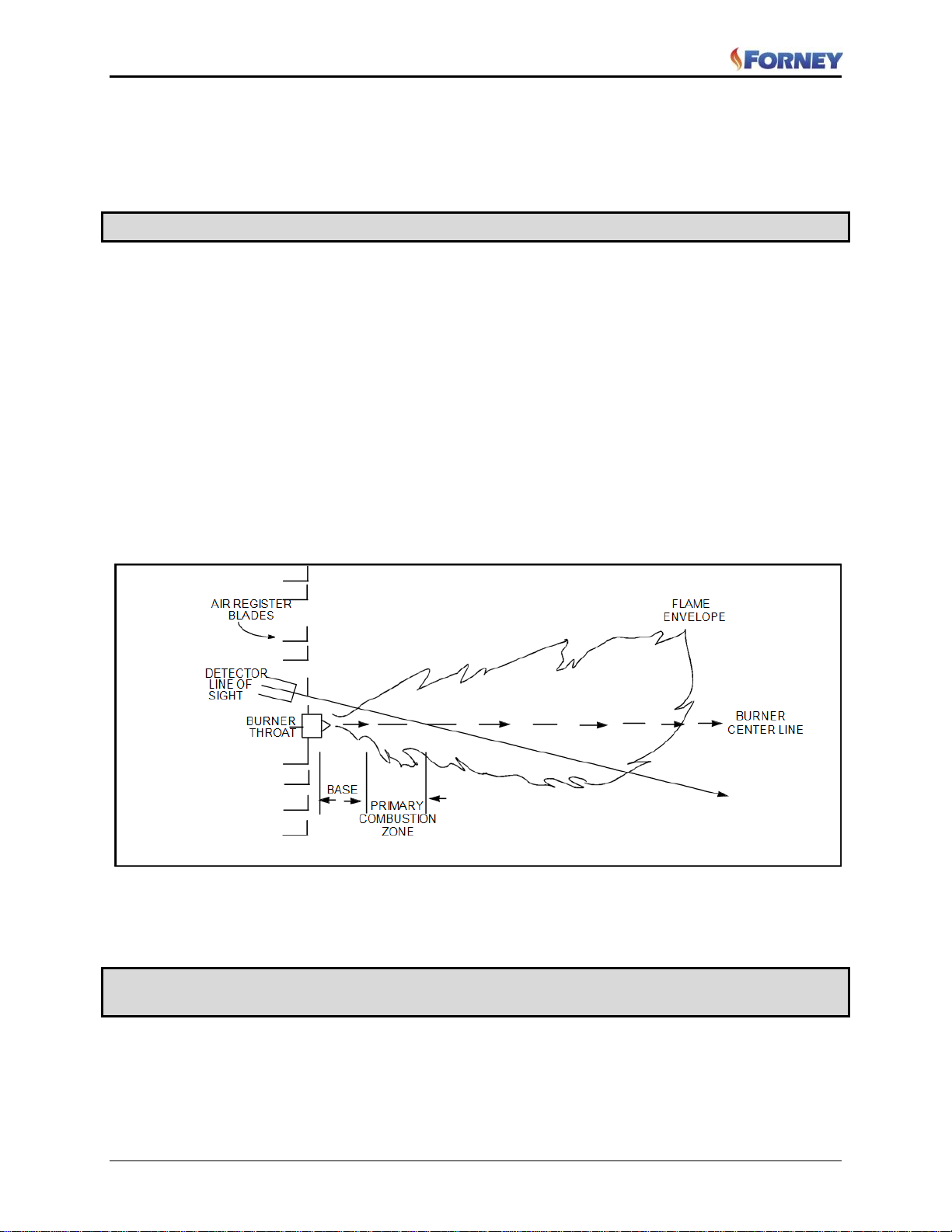
1. The best results are obtained when the detector is aimed so that the detector’s line of sight
intersects the burner center at a slight angle (e.g. 5 degrees) and sees a maximum of the primary
combustion zone, as shown in Figure 3. If only one detector is used per burner, the line of sight
should also intersect the igniting flame.
2. For installations where separate detectors are used to monitor main and igniter flames, the main
7
Page 9
IDD Flame Detector Heads Manual
372000-05 Rev J
flame detector should be sighted so it does not detect the igniter flame.
3. The detector should have an unrestricted view of flame as far as possible. Physical obstructions
such as air register blades, interfering vanes, or other hardware should be cut away or notched
so they do not fall within the detector’s line of sight as shown in Figure 3.
Note: Always check with the burner manufacturer before you trim the register blades.
2.1.1 IDD-CEX Mounting Flange
The IDD-CEX Housing requires an additional mounting flange for installation. See arrangement
drawings
Flange Material: Cast aluminum with gray polyester powder coat finish. Contains an integral heatinsulating female thread insert (external heat-insulating nipple not required).
Flange Threads: 1" NPT female pipe mount with 3/8” NPT female cooling air connection.
1" BSP female pipe mount with 3/8” BSP female cooling air connection.
Flange Weight: 0.62 lbs (0.28 kg)
Note: When installing the flange, only torque to 60 in/lbs (5 ft/lbs or 6.8Nm) on the sight pipe, else it may
damage the threads. (Hand tight plus 1 turn max)
Figure 3 Detector Sighting
4. AN ACCEPTABLE DETECTOR LOCATION MUST ENSURE THE FOLLOWING:
Reliable target flame detection.
Rejection if target flame is too short or in the wrong position
Note: Reliable signals must be obtained throughout the range of air flows and furnace loads (ranges of fuel
firing) and to meet the requirements of flame failure logics of the burner management system
8
Page 10
IDD Flame Detector Heads Manual
372000-05 Rev J
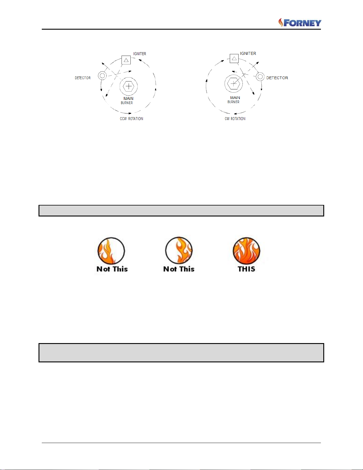
Figure 4 Detector Location VS. Secondary air rotation
5. If combustion air enters the furnace with a rotational movement of sufficient velocity to deflect
pilot flame in direction of rotation, position the detector 0 to 30 degrees downstream of the
pilot burner and close to the periphery of the throat where the ultraviolet radiation is at a
maximum. (See Figures 3 and 4)
Having determined an appropriate location for the sight tube, cut a clearance hole for a 2 inch
pipe through the burner plate. If register vanes interfere with the desired line of sight, the
interfering vane(s) should be trimmed to assure an unobstructed viewing path at all firing
levels, see example shown below.
Note: Always check with the burner manufacturer before you trim register vanes.
FLAME MUST COMPLETELY COVER SIGHT OPENING
6. The preferred method for mounting surface mounted detectors requires the use of a swivel
mount, shown in Figures 6, 8, 10 and 12. Center the swivel mount over the two inch hole in
the burner plate and secure using three hexed cap screws (not provided). Install the sight pipe
on the swivel mount. If a swivel is not used, insert the end of the sight pipe into the hole, align
the hole to the desired viewing angle and tack weld (welding must be adequate to temporarily
support the weight of the installed detector). The sight pipe should be arranged to slant
downward so that dirt and dust will not collect inside.
CAUTION: Use no more than one foot of one inch diameter sight pipe. Increase the sight pipe diameter
one inch for every additional foot of sight pipe length used to avoid restricting the detector’s field of view.
7. When a satisfactory sighting has been confirmed by operational testing, secure the swivel
mount’s ball position in place by tightening the three hex head cap screws located on the swivel
mount ring.
8. The detector lens must be kept free of contaminants (oil, ash, soot, dirt) and the detector housing
temperature must not exceed its maximum heat rating. Excessive temperatures will shorten
detector life. Both requirements will be satisfied by a continuous injection of purge air at either
the 3/8" inlet at the flange housing or the 1" wye connection ahead of the swivel mount as
shown in Arrangement Drawings.
9
Page 11
IDD Flame Detector Heads Manual
372000-05 Rev J
The detector mounting may be made with provision for purge air through only the 3/8" inlet or the 1" wye
connection. Normally purge air is provided through the 1” wye and the 3/8” inlet is plugged.
It is good practice to use the sealing coupling (P/N 9114793 NPT, 9114782 BSP) on all installations to
insure against unwanted furnace pressures from damaging the detector lens. When a sealing coupling is
used, the 1" wye connection is used for the purge air and the 3/8" opening is plugged. The sealing coupling
is located in front of the detector, behind the 1” wye/valve.
Under normal conditions, with clean burning fuels and moderate ambient temperature conditions, purge air
flow of approximately 10 SCFM (283 l/min) is generally adequate. Up to 15 SCFM
(425 l/min) may be required for fuels that produce high levels of ash or soot, or for hot environments to
maintain the detector’s internal temperature within specification.
NOTE:
If freezing temperatures are expected at the detector head, Forney recommends heat tracing the detector
sight tube. Contact Forney for additional details.
CAUTION: To ensure safe and reliable detection it is the responsibility of the commissioning engineer to
carry out flame failure testing after programming the detector.
Ensure that the detector correctly detects the target flame (Flame On condition) and recognizes the target
flame off (Flame Off condition).
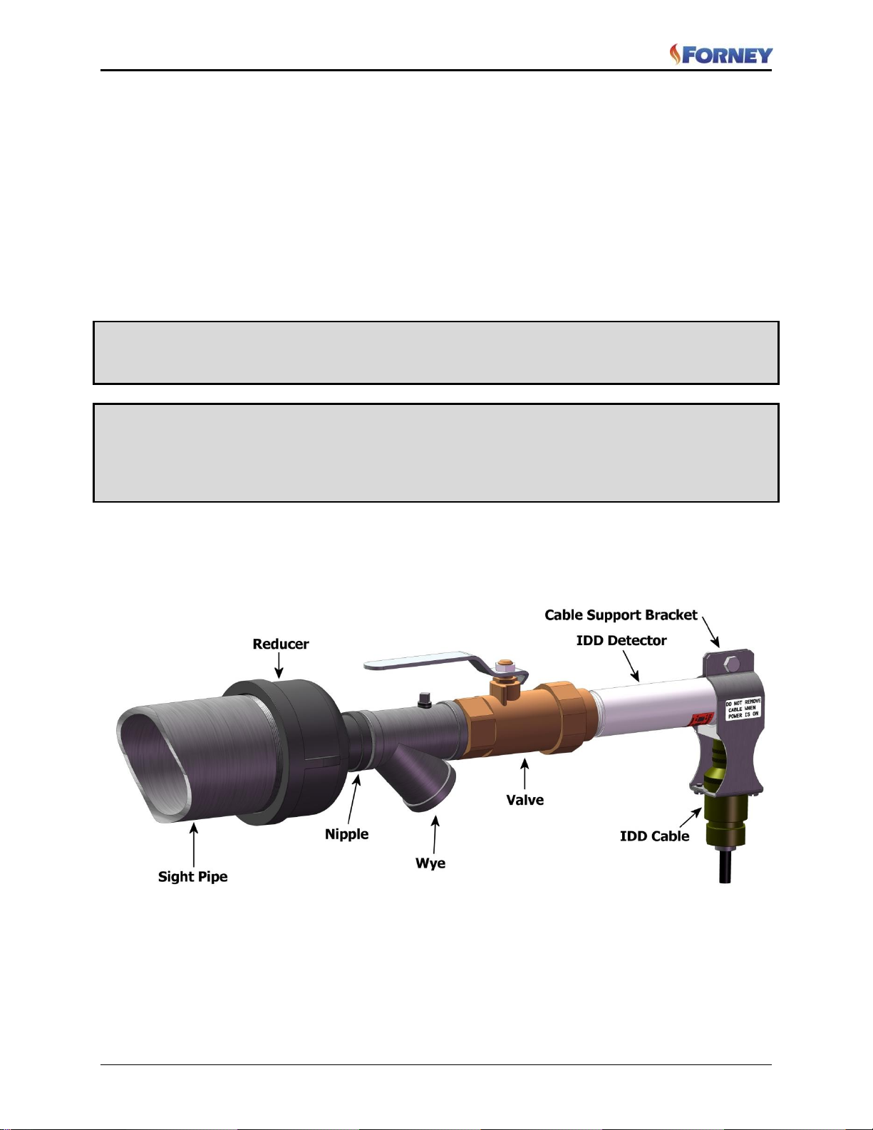
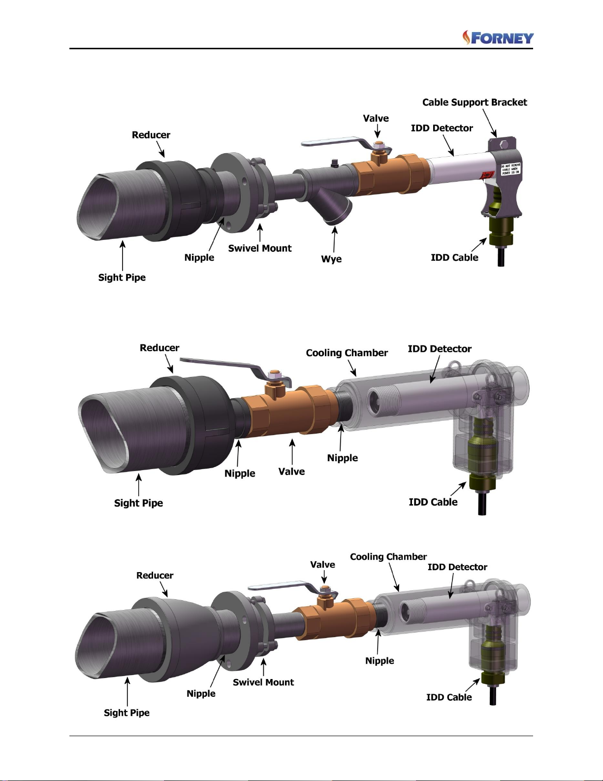
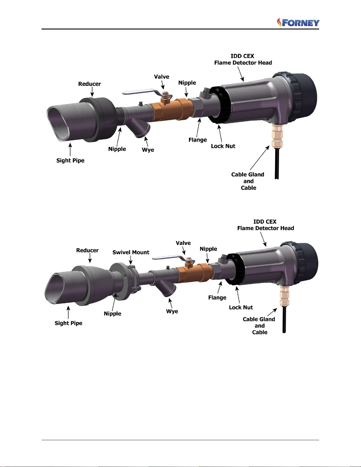
Refer to Parts section at the end of this manual for applicable part numbers of items shown in arrangement
drawings.
Figure 5 IDD Direct Mount Arrangement
Cable support bracket is required on Standard IDD when a cooling chamber is not used.
10
Page 12
IDD Flame Detector Heads Manual
372000-05 Rev J
Figure 6 IDD Swivel Mount Arrangement
Cable support bracket is required on Standard IDD when a cooling chamber is not used.
Figure 7 IDD Direct Mount with Cooling Chamber
Figure 8 IDD Swivel Mount Arrangement with Cooling Chamber
11
Page 13
IDD Flame Detector Heads Manual
372000-05 Rev J
Figure 9 IDD-CEX Direct Mount Arrangement
Figure 10 IDD-CEX Swivel Mount Arrangement
12
Page 14
IDD Flame Detector Heads Manual
372000-05 Rev J
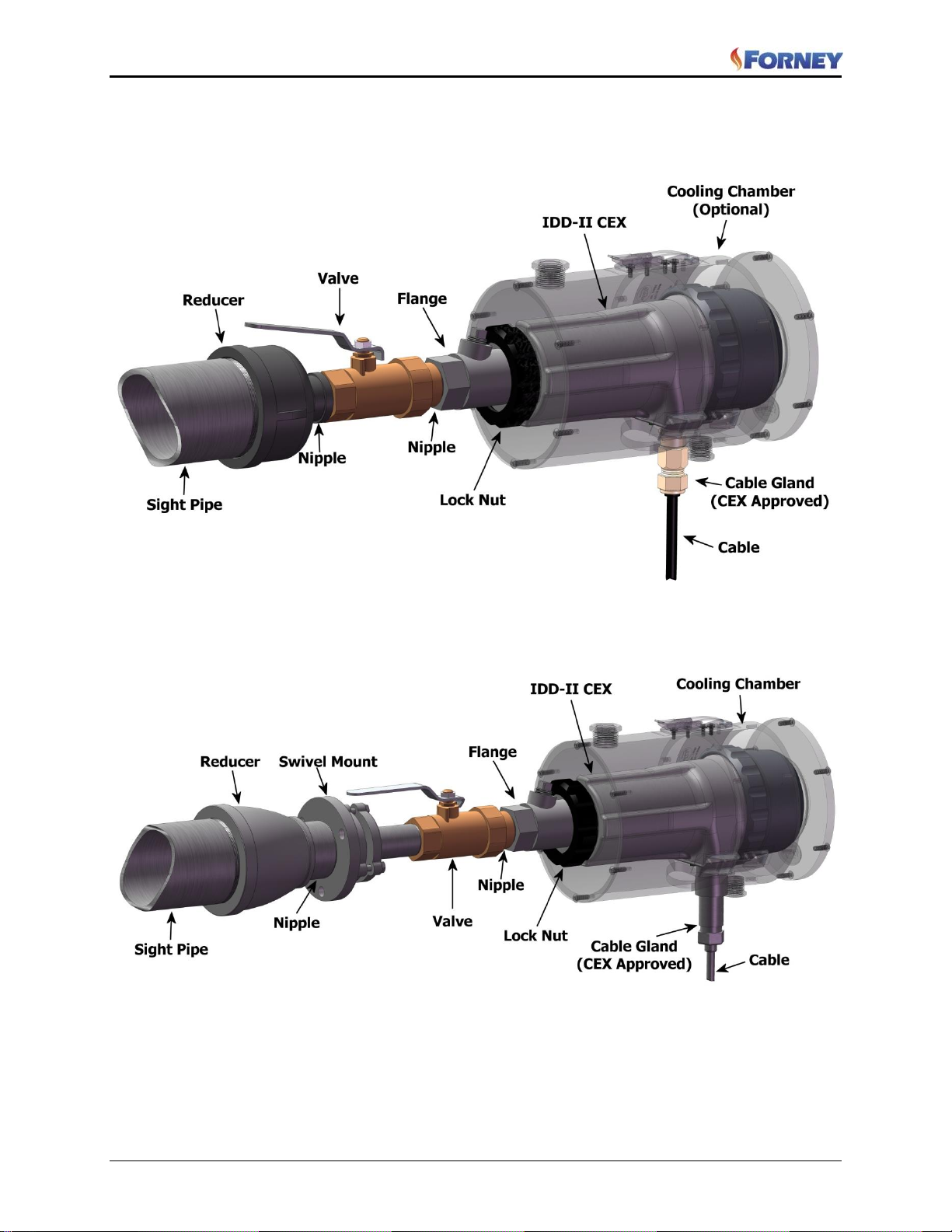
Figure 11 IDD-CEX Direct Mount Arrangement with Cooling Chamber
Figure 12 IDD-CEX Swivel Mount Arrangement with Cooling Chamber
13
Page 15
IDD Flame Detector Heads Manual
372000-05 Rev J
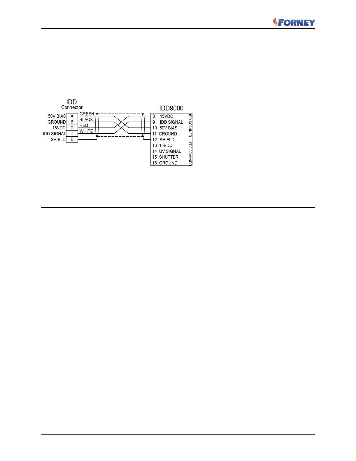
2.2 Detector Wiring
To reduce electrical noise interference, the detector cable should be installed in flexible or rigid conduit.
Take precautions to keep the detector cable away from any high inductive wiring associated with high
inductive loads or high voltage, or high energy spark ignition systems.
Figure 13 Sample Wiring Diagram for IDD Detector Head to Amplifier
Refer to specific Forney Amplifier manual for specific wiring instructions for other amplifiers.
Section 3 Commissioning
Before commissioning, complete all of the installation instructions.
3.1 Checkout Procedure
3.1.1 Initial Checkout
Verify the interconnection between detector head and the amplifier; confirm to applicable wiring diagram
for the specific amplifier.
1. Verify the operation of the detector head as follows:
a) Remove mounted IDD detector head.
b) Connect it to the four-conductor cable.
c) Place a light source 1 to 4 feet from the surface of the detector. Use a Tungsten light source for IR
detector heads and a UV light source for the IDD-Ultra.
d) At the signal input terminal of the detector amplifier, measure the signal with either a digital
voltmeter (DVM) or oscilloscope to be 0.1 to 8.0 vac, peak to peak.
e) Remove all light supplied to the detector cell, and verify loss of signal.
2. After checkout, return the system to normal configuration.
3.1.2 Operational Checkout
1. With burner in service, verify signal input to the detector amplifier.
2. Adjust the amplifier per the applicable Forney Corporation service manual.
3. Amplifier gain / frequency adjustments must be made by cycling target flame on/ off and changing
the target burner firing rate from minimum to maximum. Settings must be verified during burner
operation at different boiler loads to ensure discrimination requirements are met.
14
Page 16

IDD Flame Detector Heads Manual
Symptom
Probable Cause
Remedy
No signal output
Supply voltage to head not present.
Verify +50 vdc and +12 to +14.5
vdc to detector.
Detector head assembly not
functional.
Replace detector.
Overheated detector head.
Verify surface of detector is less
than 140° F (60°C). Correct high
temperature as necessary.
Detector not receiving sufficient
signal.
Aim the detector at the base of
the flame to be viewed. The
detector must view flame flicker.
Check alarm
Noise on output signal.
Ensure amplifier chassis is
grounded.
Check for broken cable wire.
Replace detector.
Reroute cable if not in a shielded
cable tray.
Weak detector (PPS) output
Detector not receiving sufficient signal
Aim the detector at the base of
the flame to be viewed. The
detector must view flame flicker.
Target flame intensity is weak.
Consult engineering.
372000-05 Rev J
Section 4 Operation
The IDD detector head is sighted at the first 1/3 of the flame or the primary combustion zone of the burner.
The radiant energy from the flame is viewed either directly through a straight piece of pipe or transmitted
to the surface of the detector cell through a fiber-optic assembly. The cell in the detector on which the
radiant energy falls is biased with a +50 vdc source. As the intensity of the flame’s radiation increases and
decreases, it causes a change in resistance of the cell substrate. This resistance change in turn creates a
varying ac voltage output that is proportional to the amount rate of change of the radiant flame energy.
IMPORTANT:
The detector must be sighted properly to sense sufficient flame radiation. Improper sighting may cause
detector failure due to a weak or non-existent signal.
The signal is transmitted to the applicable flame detector amplifier through a four-conductor shielded cable.
The output signal from the IDD detector head is totally dependent on the flame radiation from the burner
and the sighting of the primary combustion zone.
Section 5 Troubleshooting
If the detector head malfunctions, ensure that the procedures described in the commissioning section have
been performed successfully.
Refer to Table 1 for Troubleshooting information.
TABLE 1: IDD Detector Head Troubleshooting
15
Page 17

IDD Flame Detector Heads Manual
Phone
Fax
Web
(972) 458-6100,
(972) 458-6142
or
24-hour direct line
1-800-356-7740
(972) 458-6600
Fill out the online form at
http://www.forneycorp.com/return-material-authorizations-rma/
372000-05 Rev J
Section 6 Maintenance
The IDD detector head is a non-repairable device and requires no maintenance other than periodically
cleaning the cell surface. The appropriate cleaning schedule is determined by the quality and cleanliness
of the cooling-/seal-air source. Forney recommends the use of a non-oily cleaning solution and a soft lintfree cloth for lens cleaning.
Section 7 Storage
Store the IDD detector head in its shipping box until used. Refer to the Section 1.2 Mechanical
Specifications for acceptable storage temperature ranges.
Section 8 Return or Repair Service
Forney Corporation warrants this product to be free of defective material and workmanship. Forney will
repair or replace this equipment if it is found to be defective on receipt, but no later than 90 days from the
date of shipment.
Prior to returning any material to Forney, obtain a Return Material Authorization (RMA) identification
number from Forney. Clearly mark the RMA number on all shipping containers and accompanying
documents. Forney accepts only material submitted in accordance with the RMA instructions.
To issue an RMA, Forney must have the following information:
List of Equipment to be returned by stock number/model number
Reason for return
Company name and address of customer
Customer’s requested mode for return shipping
Customer’s purchase order number for repairs (if applicable)
Customer’s requested return date
Name and address to which Forney is to return-ship and any special container marking information
that may be required
Name of individual (customer’s representative) requesting the RMA.
Any of the following methods may be used to obtain an RMA:
Forney Corporation is not responsible for materials returned without proper authorization and
identification.
Exercise care in packing the materials to be returned. The shipper will be advised of any damage due to
improper packing; no further action will be taken in connection with this material return until the shipper
provides clearance for further disposition.
16
Page 18
IDD Flame Detector Heads Manual
Phone
Fax
Mail
(972) 458-6100 or 458-6142
24-hour direct line
1-800-356-7740
(972) 458-6600
Attn: Spare Parts Department
Forney Corporation
16479 N. Dallas Parkway, Suite 600
Addison, TX 75001
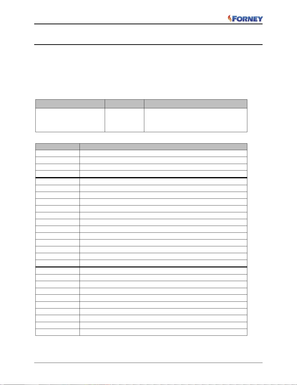
Part Number
Description
38321-21
IDD-II IR Detector Filtered (700 to 3300 nanometers)
38321-22
IDD-IIU IR Detector Unfiltered (400 to 3300 nanometers)
38321-23
IDD-IIL IR Detector (700 to 3300 nanometers; for lignite)
38321-29
IDD-Ultra UV Detector (200 to 425 nanometers)
399854-xx
Detector cable with connector (-xx consult Forney for available lengths)
364524-01
Cable support bracket
381071-01
Cooling air chamber (Standard IDD version)
354943-01
1” NPT Valve and wye assembly
311027-01
1” NPT Insulating nipple
74947-03
3” to 1” NPT Reducer
74947-05
3” to 2” NPT Reducer
75450-06
1” NPT Close nipple
75450-09
2” NPT Close nipple
92527-02
IDD-CEX Cooling chamber
91016-63
1” NPT Swivel
91147-93
1” NPT Sealing Coupling
91147-82
1" BSP Sealing Coupling
38321-25
IDD-IICEX IR Detector Filtered (700 to 3300 nanometers)
38321-26
IDD-IILCEX IR Detector (700 to 3300 nanometers; for lignite)
38321-27
IDD-IIUCEX IR Detector Unfiltered (400 to 3300 nanometers)
401116-50
1" NPT female pipe mount with 3/8” NPT female cooling air connection
401116-60
1" BSP female pipe mount with 3/8” BSP female cooling air connection
92437-02
3/8” NPT Purge air plug
92437-15
3/8” BSP Purge air plug
77923-50
Armored cable, 2 pair
77215-54
Cable gland & lock nut
77215-55
Cable gland
372000-05 Rev J
Section 9 Parts
When ordering parts, furnish the following information:
Contract number
Customer purchase order number
For each part ordered, provide the following information:
o Part Number
o Part Description
o Quantity Required
TABLE 2: IDD Detector Head Assembly Parts
17
 Loading...