

Page 1

FD 6102
Low-Volume Inserter
Operator Manual
9/2011 First Edition
Page 2

ENGLISH
TABLE OF CONTENTS
1 Health, Safety and Environment ...................................................... 2
1.1 Precautions and Safety Issues ................................................... 2
1.2 Country Specific Conditions ...................................................... 3
1.3 End of Life .............................................................................. 4
2 Functional description ..................................................................... 5
2.1 The Folding and Inserting Process .............................................. 5
2.2 Operating Controls .................................................................. 7
2.3 Control Panel .......................................................................... 8
2.4 User Interface Description ........................................................ 8
3 Operating Instructions .................................................................. 11
3.1 Installing the Envelope Catch Tray ............................................ 11
3.2 Starting Up ............................................................................ 11
3.3 Loading Documents ................................................................ 12
3.4 Loading Envelopes .................................................................. 14
3.5 Filling the Sealing Liquid Reservoir ............................................ 15
3.6 Run a Job .............................................................................. 15
3.7 Daily Mail .............................................................................. 16
3.8 Stopping the system ............................................................... 16
4 Job Programming .......................................................................... 17
4.1 Create a Job .......................................................................... 17
4.2 Edit a Job .............................................................................. 18
4.3 Delete a Job .......................................................................... 18
5 Operator Maintenance ................................................................... 19
5.1 Cleaning or Replacing Moistening Brushes .................................. 19
5.2 Clean the System ................................................................... 19
6 Fault finding .................................................................................. 20
6.1 Error Messages ...................................................................... 20
6.2 Clearing Stoppages ................................................................. 20
6.3 Operator Troubleshooting ........................................................ 22
7 Specifications ................................................................................ 27
7.1 Technical Specifications ........................................................... 27
7.2 Dimensions ........................................................................... 27
7.3 Other Specifications ................................................................ 27
7.4 Document Specifications ......................................................... 27
7.5 Envelope and Insert Specifications ............................................ 28
8 Terminology .................................................................................. 29
Index.............................................................................................. 34
1
Page 3

1. HEALTH, SAFETY AND ENVIRONMENT
1.1 Precautions and Safety Issues
Thoroughly read this operator manual, before using this system.
According to the EC declaration (European Commission) following the Low Voltage
Directive (2006/95/EC), this operator manual must be available in the national
language(s) of the country where the system is delivered. Therefore, if you do not have an
operator manual in your country’s language(s), contact your authorized distributor.
Warnings
• Disconnect the mains supply before performing any maintenance.
• Before connecting check if the system is suitable for the local mains voltage. Refer to
the type plate.
Safety Precautions
• Only trained personnel should operate this system.
If untrained personnel do operate this system
responsibili
• Only service technicians, who are aware of the risks involved, may open the protective
covers.
For safety reasons, the system will not function when the covers are open.
• Keep long hair, fingers, jewelry, etc. away from rotating and moving parts.
• The power connection must be easily accessible, preferably close to the system.
• For safety reasons, it is essential that the system is connected to a socket outlet that
has a protective earth connection.
• Over-current protection in the equipment also relies on the branch circuit protection
(max. 20 A).
• The following part is considered the equipment disconnect device:
- Power supply cord plug or appliance coupler
ty for any resulting accidents or injuries.
, the manufacturer does not accept
2
Page 4
ENGLISH
Conventions
Warning
This symbol:
• Identifies situations where improper use of the system can result in
personal injury or permanent/catastrophic damage to the system.
• Indicates that the operator manual should be consulted.
Note
A note gives additional relevant information.
Caution
Indicates the presence of a hazard that can cause personal injury or property damage, if
the hazard is not avoided.
1.2 Country Specific Conditions
Denmark
In Denmark, certain types of Class 1 appliances may be provided with a plug that does not
provide an adequate earth connection when inserted into a Danish socket outlet.
Make sure the system has a good functioning connection that has protective earthing (the
plug and socket outlet must match).
Japan
• Establish an earth connection before connecting the mains plug to the power supply.
• First disconnect the power supply before removing the earth connection.
Languages
This manual is also available in other languages. For more information, please contact
your local supplier.
3
Page 5
1.3 End of Life
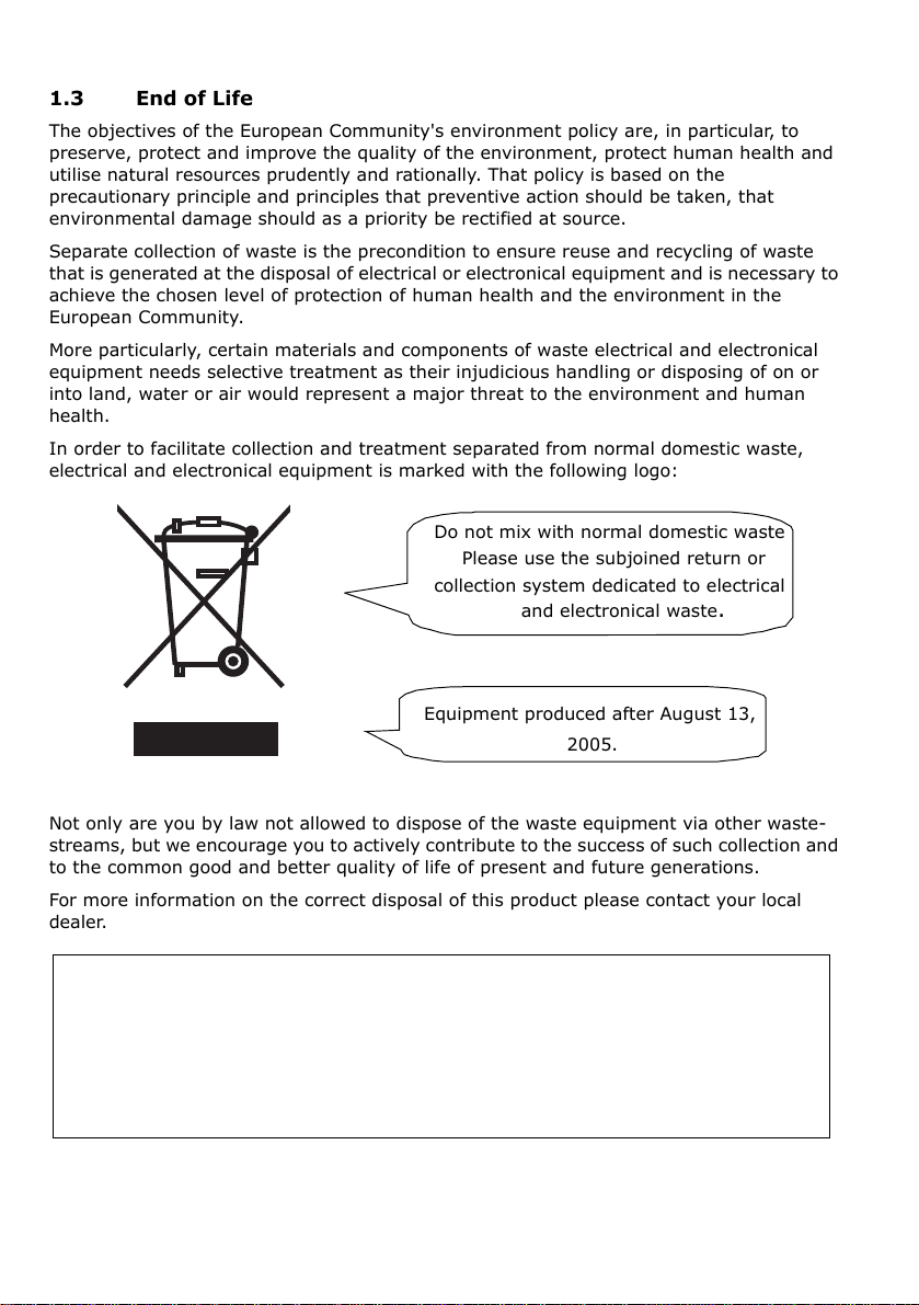
Do not mix with normal domestic waste
collection system dedicated to electrical
and electronical waste.
Please use the subjoined return or
Equipment produced after August 13,
2005.
The objectives of the European Community's environment policy are, in particular, to
preserve, protect and improve the quality of the environment, protect human health and
utilise natural resources prudently and rationally. That policy is based on the
precautionary principle and principles that preventive action should be taken, that
environmental damage should as a priority be rectified at source.
Separate collection of waste is the precondition to ensure reuse and recycling of waste
that is generated at the disposal of electrical or electronical equipment and is necessary to
achieve the chosen level of protection of human health and the environment in the
European Community.
More particularly, certain materials and components of waste electrical and electronical
equipment needs selective treatment as their injudicious handling or disposing of on or
into land, water or air would represent a major threat to the environment and human
health.
In order to facilitate collection and treatment separated from normal domestic waste,
electrical and electronical equipment is marked with the following logo:
Not only are you by law not allowed to dispose of the waste equipment via other waste-
streams, but we encourage you to actively contribute to the success of such collection and
to the common good and better quality of life of present and future generations.
For more information on the correct disposal of this product please contact your local
dealer.
4
Page 6
ENGLISH
2. FUNCTIONAL DESCRIPTION
The system feeds, folds and inserts documents into envelopes and then seals and stacks
the envelopes. Automatic monitoring ensures the correct number of inserts per envelope.
The system is a sophisticated folding and inserting system which can process large
quantities of mail rapidly and easily.
You can save the settings of the system (document type, envelope type and fold type) as
jobs.
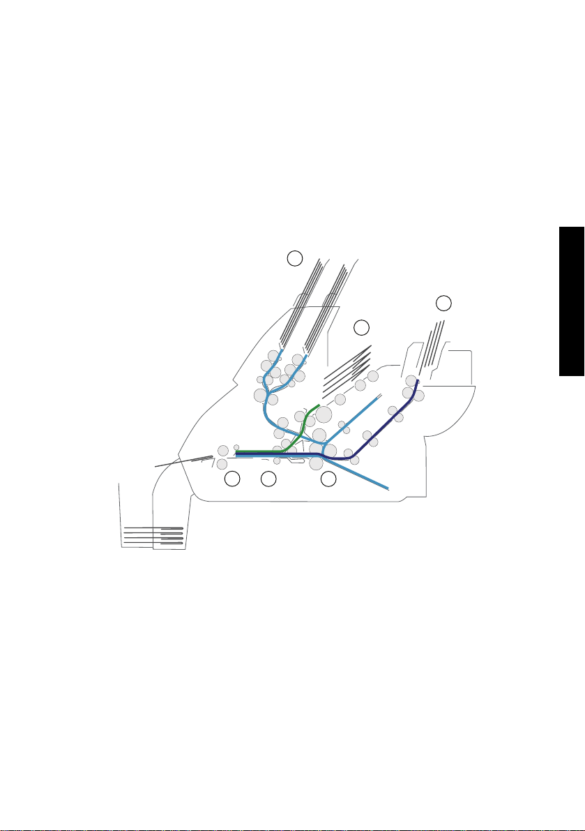
2.1 The Folding and Inserting Process
The figure shows an overview of the document and envelope flow.
1
3
2
6
5
Feeder Area (1)
The system has a feeder block with two document feeders. The feeder block is equipped
with hopper swap. This means that you can link both feeders as pairs. When the first
feeder is empty, the system switches to the other feeder. Meanwhile you can refill the
other empty feeder without stopping the system.
The front feeder (feeder 1) is equipped with a “daily mail” function to process documents
or sets of documents which cannot be processed automatically (e.g. stapled).
4
5
Page 7

Double Feed Control (DFC)
Each feeder has double feed control (DFC). In this way the system can detect faulty sets
of documents. When a job is started, the first document taken per feeder is used for a
reference measurement. When a document is exceeding that reference thickness an error
will be displayed.
Note
When Daily mail is selected, the DFC is switched off automatically.
Envelope Hopper (2)
The envelopes are picked up and transported to the insert position inside the system.
Feeder for Business Reply Envelopes (BRE) and Other Enclosures
(feeder 3)
Small enclosures or BREs are fed from feeder 3 and added to the folded document set.
Folding area (4)
In the folding area the documents are folded. The following fold types are possible (see
“Terminology” on page 29):
•No fold
• V-fold (half fold)
• C-fold (letter fold)
• Double V-fold (double parallel fold)
Inserter (5)
The folded document set is transported to the inserter unit and inserted into a waiting
envelope. The inserter can seal the envelope.
Exit (6)
The mail set leaves the system from the exit.
6
Page 8
ENGLISH
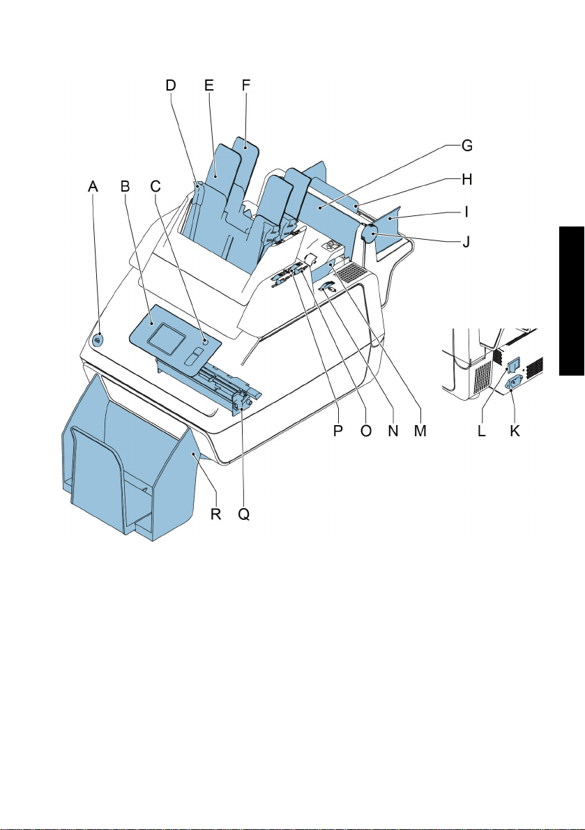
2.2 Operating Controls
A button to open the system K power inlet
B control panel with touch screen L power switch
C standby button M side guides envelope hopper
D paper guides N thumb wheel for adjusting side guides
envelope hopperE document feeder 1
F document feeder 2 O locking lever for side guides of document
feeder tray 2 and for filling tray 2G flap, for access to document path
of feeder 3 P thumb wheel for adjusting side guides
H support feeder 3 document feeder tray 2
I side guides feeder 3 Q sealing liquid reservoir
J thumb wheel to adjust side guides
feeder 3
Rcatch tray
7
Page 9
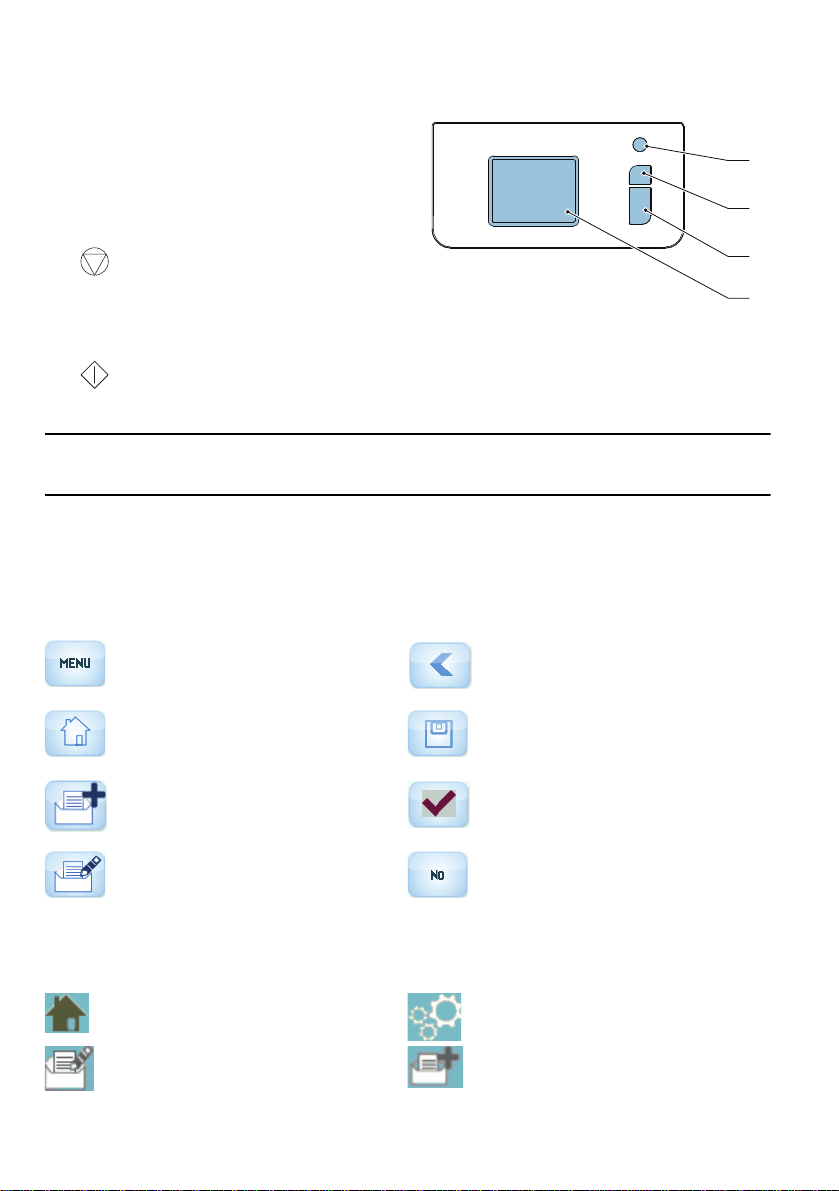
2.3 Control Panel
A
The system has a touch screen (D).
There are three buttons next to the touch
screen:
• Standby button A to switch the system
on or off.
B
•: the stop key (B)
When the stop key is pressed, the
system completes the current set and
stops.
• : the start key (C)
When the start key is pressed the system starts processing.
Caution
The touch screen is covered with a thin pressure-sensitive layer. To avoid permanent
damage of the touch screen, do not use sharp objects to press on the touch screen.
2.4 User Interface Description
2.4.1 Explanation of Buttons and icons
Buttons
Opens a selection menu with
language settings and supervisor
menu
Home: return to the ‘job selection’
menu
New job: create a new job OK or Yes: confirm choice
Back: return to the previous menu
Save: save changes to a job
C
D
Edit: open the ‘job settings’ menu No: reject choice
Meaning of Icons in Upper Left Corner of Touch Screen
The icons in the upper left corner indicate the menu type you are working in.
Home menu or ‘job selection’ menu Settings
‘job settings’ menu Wizard
8
Page 10
ENGLISH
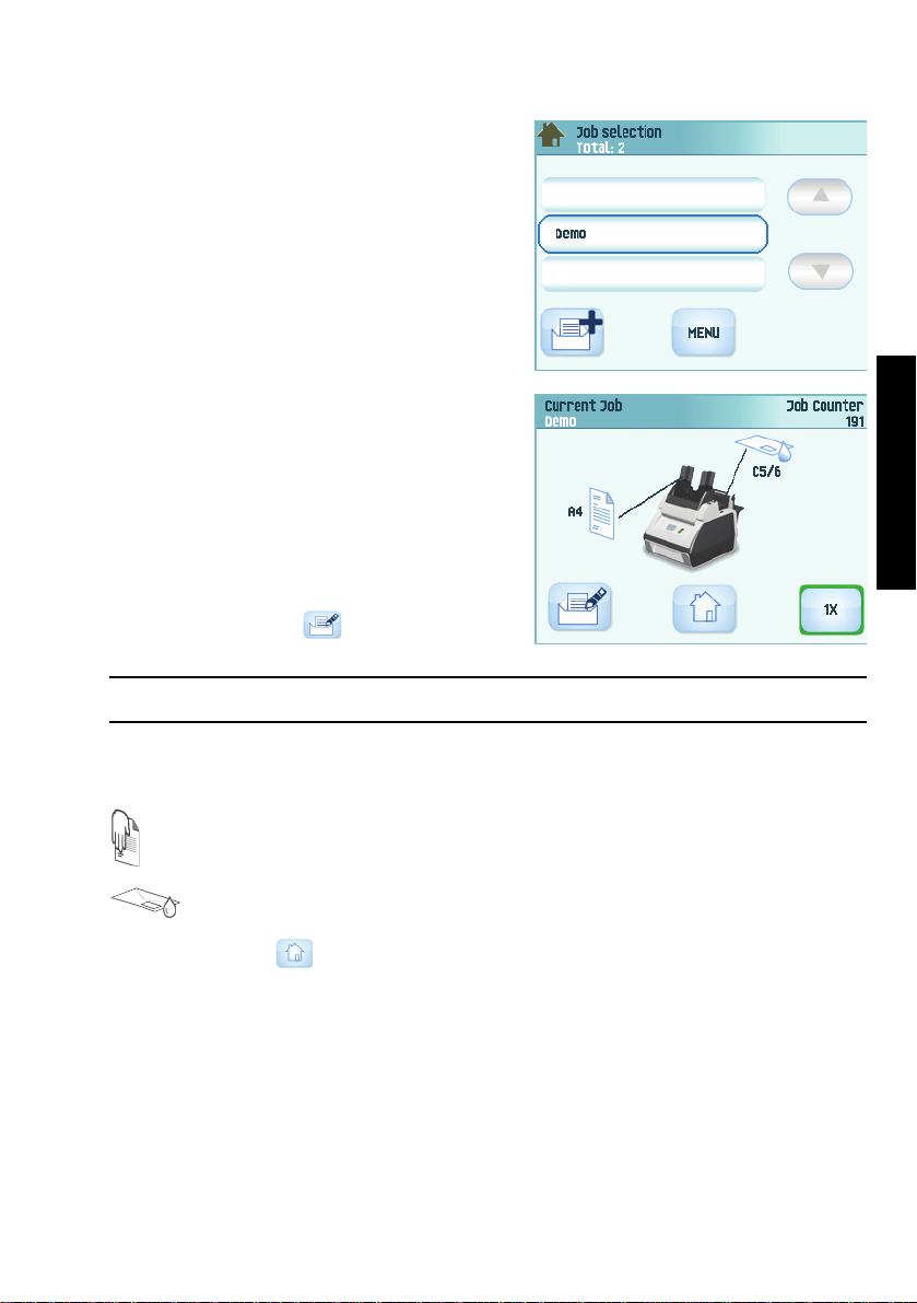
2.4.2 Home (Job Selection)
When you start up the system, the home menu
‘job selection’ appears. With the arrows you can
scroll through the jobs. If you want more
information on a job, select the job (see
2.4.3 ”Job Description (Current Job)” on page 9).
The Menu button opens a selection menu (see
2.4.4 ”Menu” on page 10).
With the New Job button you can define a new
job (see “Create a Job” on page 17).
2.4.3 Job Description (Current Job)
If you want more information on a job, select the
job in the ‘job selection’ menu.
The ‘current job’ menu shows the following
information of the selected job:
•Job name.
• Job counter: total number of mail sets that
have been processed with this job.
If you want to set the job counter to zero,
press the edit button and Reset job
counter.
Note
The counter settings are job related.
• A picture of the system with symbols for the selected features. The following symbols
can be used:
Feeder 1 is set for daily mail.
Sealing is on.
With the home button you get back to the home menu (‘job selection’).
9
Page 11
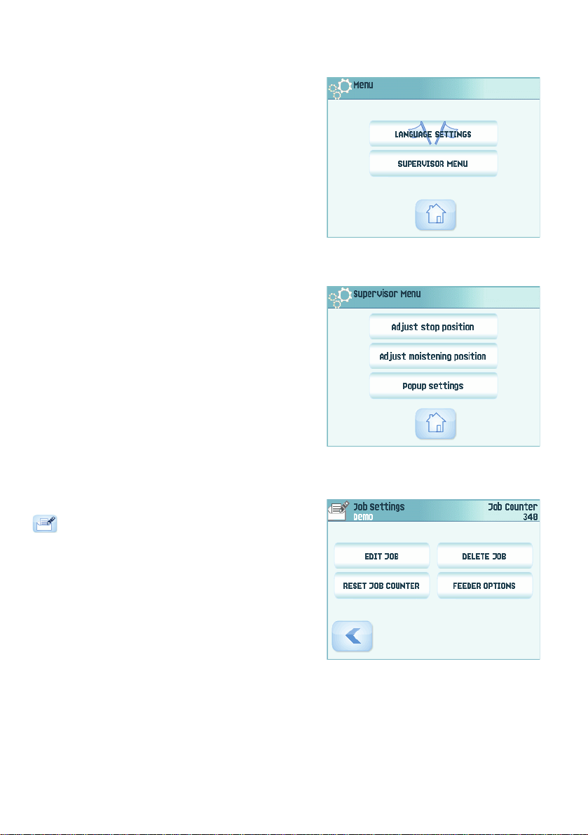
2.4.4 Menu
When you press the Menu button a selection
menu appears. This menu allows you to change
system settings and define jobs. The screen
shows the following functions:
• Language settings: change the language of
the user interface.
• Supervisor menu: define envelope settings
(see “Supervisor Menu” below, o
auth
orized personnel).
nly for
2.4.5 Supervisor Menu
When you press the Supervisor menu button in the selection menu, a login menu opens.
Enter the PIN-code 2546 to access the ‘supervisor menu’.
When you enter the correct pin code the
‘supervisor menu’ appears. This menu enables
you to:
• Define custom envelope sizes (press the
Adjust stop position button).
• Adjust the envelope stop position (see
“Envelope Position” on page 26).
• Adjust the sealing position (see “Sealing
position” on page 26).
• Switch off popups, like the popup that tells
you to press the 1x button.
2.4.6 Job Settings Menu
When you press on a job and press the edit button
, the ‘job settings’ menu opens. This menu
enables you to:
• Edit a job (see 4.2 ”Edit a Job” on page 18).
• Delete a job (see 4.3 ”Delete a Job” on page
18).
• Reset the job counter: sets counter to zero.
• Switch the double feed control (DFC) on or
off, per feeder. For example, if you have a
document with an address sticker on it,
switch the DFC off. The DFC sees the sticker as a double feed and generates an error
message.
10
Page 12

ENGLISH
3. OPERATING INSTRUCTIONS
3.1 Installing the Envelope Catch
Tray
To install the envelope catch tray:
1. Move the catch tray until the clamps hold the
feet of the system.
2. Adjust the catch tray to the correct envelope
size.
3.2 Starting Up
Warning
You can severely damage the system if it is connected to the incorrect power supply.
Before plugging in the system, check if the local voltage is the same as the voltage
mentioned on the type plate.
For the location of switches and buttons, see “Operating Controls” on page 7.
To start up the system:
1. Connect the system to the mains power
supply.
2. Use the power switch to switch the system
on. The power switch is located at the back of
the system.
3. Press the power button next to the display.
The touch screen shows the home menu.
11
Page 13

3.3 Loading Documents
3.3.1 Document Orientation
See also the job information on the touch screen. The table shows how to load documents,
depending on the fold type.
V-fold
C-fold
double
V-fold
no fold
one document
1
Address carrier in
feeder 1.
Face up and trailing.
3
Address carrier in
feeder 3.
Face up and trailing.
feeder linking
2
1
Address carrier in
feeders 1 and 2.
Face up and trailing.
two documents
2
1
Address carrier in
feeder 1.
Face up and trailing.
document + enclosure
1
Address carrier in
feeder 1.
Face up and trailing.
3
12
Page 14

ENGLISH
3.3.2 Adjusting the Side Guides of the
A
Document Feeder
To adjust the side guides of the document feeder
trays:
1. Pull lever C.
2. Move the side guides A apart as far as possible
with thumb wheel B.
3. Put a small stack of documents between the
side guides.
4. Move the side guides towards the documents
with thumb wheel B.
The space between the side guides and the
documents should be such that the documents
have just enough play to move freely.
5. Return lever C to its original position.
6. Remove the stack of documents.
3.3.3 Loading the Document Feeder
Tray
To load the document feeder tray:
1. Pull lever C at the tray.
2. Place a stack of documents between the side guides.
Feed the documents (depending on the type of documents) as shown in
3.3.1 ”Document Orientation” on page 12.
3. Return lever C to its original position.
3.3.4 Adjusting the Side Guides of
Feeder 3
To adjust the side guides of feeder 3:
1. Move the side guides C apart as far as
possible with thumb wheel D.
2. Pull back support B.
3. Put a small stack of enclosures (A) between
the side guides.
4. Release support B.
5. Move the side guides towards the enclosures
with thumb wheel D.
The space between the side guides and the
enclosures should be such that the enclosures
have just enough play to move freely.
6. Remove the stack of enclosures.
B
C
D
13
Page 15

3.3.5 Loading Feeder 3
To load feeder 3:
1. Pull back support B.
2. Place a stack of documents or BREs between the side guides.
Place documents with trailing edge down. Place BREs with leading edge down and the
flap at the support side.
3. Release support B.
3.4 Loading Envelopes
To load the envelopes:
1. Move the side guides B apart as far as
possible with thumb wheel A.
2. Fan the stack of envelopes C and place
them between the side guides (flap down
and trailing - bottom side of envelope
pointing to the system).
3. Move the side guides towards the
envelopes with thumb wheel A.
The space between the side guides and
the envelopes should be such that the
envelopes have just enough play to move
freely.
BA C
Note
If the distance between the side guides is too large, the envelopes will skew, when
transported into the system.
14
Page 16

ENGLISH
3.5 Filling the Sealing Liquid Reservoir
When you want to seal envelopes,
the sealing liquid reservoir must be
filled.
1. Press the button to open
the system (see “Operating
Controls” on page 7).
2. Lift the sealing liquid reservoir
D with the blue handles A
carefully out of the system.
3. Remove the strip C from the
reservoir.
4. Fill the three reservoirs with
sealing liquid.
5. Make sure the brushes B are
moistened sufficiently.
6. Replace the liquid reservoir.
7. Close the system.
Before you start the job, wait
approximately 5 minutes for the
brushes to moisten.
3.6 Run a Job
Note
Before you run a job, make sure the sealing liquid reservoir is filled.
To run a job:
1. From the home menu choose a job.
The job information appears (see “Job
Description (Current Job)” on page 9).
2. Load envelopes as specified in the job.
3. Load the documents face up and trailing, as
specified in the job.
Place the address carrier in feeder 1.
4. Press the 1x button to start a test run or
press the button to start the job.
If you press the 1x test button, the system helps you to adjust the address position
(see 6.3.7 ”Address Position” on page 26).
15
Page 17

3.7 Daily Mail
To process documents or sets of documents, which can not be processed automatically
(e.g. stapled documents), you can use feeder 1 as a daily mail feeder. Daily mail can
handle sets with a maximum of five sheets (80 g/m
1. To use the daily mail function, define a new job with daily mail (see “Job
Programming” on page 17) or use an existing daily mail job.
2. Place the document or document set in the feeder 1.
3. Press the button to start the job.
The document or document set will be folded and inserted into the envelope as
defined in the selected job.
4. Place the next document or document set in the feeder. The system will keep running
to process the inserted document or document set.
5. When finished with Daily Mail, press the button to stop the job.
2
).
3.8 Stopping the system
To stop the system press the button. The system completes and inserts the current
set and stops. This results in a cleared system which is ready to process a new job.
16
Page 18

ENGLISH
4. JOB PROGRAMMING
4.1 Create a Job
To cre a t e a new jo b :
1. In the home menu, press the (new job)
button.
The Job Wizard starts and helps you to
choose:
- Envelope size. Custom is only available if
defined by the supervisor (“Supervisor
Menu” on page 10).
- If the envelopes should be sealed or not.
- Document size for feeder 1.
- Daily mail or normal documents.
- Document size for feeder 2. If you choose None, you can use feeder 2 as a linked
feeder. This means that when one feeder is empty, the system automatically
starts picking documents from the other feeder.
- Enclosure size (from feeder 3).
-Fold type.
2. Press the 1x button to make sure that the address position is correct (see “Address
Position” on page 26).
3. Press the button to start the job or press the button to save the job.
4. If you press the button:
a Enter a name for the job. Use the < button to clear a character left of the cursor
position (backspace).
b Press the > button to confirm the job name.
17
Page 19

4.2 Edit a Job
To edit an existing job:
1. From the home menu choose a job.
2. Press the edit button .
The ‘job settings’ menu opens.
3. Press Edit job.
The Job Wizard starts and helps you to
change job settings.
4. Press Save to save the job with the changed
settings.
5. Press the 1x button to make sure that the
address position is correct (see “Address Position” on page 26).
4.3 Delete a Job
To delete an existing job:
1. From the home menu choose a job.
2. Press the edit button .
The ‘job settings’ menu opens.
3. Press Delete job.
4. Press the Yes button to confirm.
The job will be deleted without a warning.
18
Page 20

5. OPERATOR MAINTENANCE
Warning
• Disconnect the mains power supply before performing any maintenance.
The user must not attempt to service the system beyond that described in
this operator manual. All other servicing must be carried out by qualified
service personnel only.
Please contact your authorized distributor.
Maintenance
frequency
Daily • Check the system functions.
Weekly • When dirty or saturated, clean the brushes of the envelope sealing
Maintenance
• Keep the system in proper condition by removing dust, paper
remains, etc.
• When dirty, clean the sealing table and rollers with a slightly wetted
cloth, soaked in warm water.
(see “Cleaning or Replacing Moistening Brushes” below).
• Clean rollers (see “Clean the System” below).
5.1 Cleaning or Replacing Moistening Brushes
See “Filling the Sealing Liquid Reservoir” on page 15 for the location of the brushes.
1. Open the system.
2. Lift the sealing liquid reservoir with the blue handles carefully out of the system.
3. Remove the three brushes.
4. Clean the brushes with a small amount of water.
If the brushes are worn, replace them with new ones.
5. Install the brushes.
6. Fill the tray with sealing liquid.
7. Make sure the brushes are moistened sufficiently.
8. Replace the liquid reservoir.
9. Close the system.
ENGLISH
5.2 Clean the System
1. Open the system.
2. Clean the rollers. Use a cleaning product recommended by your authorized distributor
and apply it with a lint-free cloth. Wipe each rubber roller while turning it manually.
3. Clean the casing of the system with a damp cloth and a slightly soapy solution.
19
Page 21

6. FAULT FINDING
6.1 Error Messages
When an error occurs the touch screen shows a
menu showing the following information:
•An indication of the area in which the error
occurred.
• An error description.
• A suggested solution.
Special Errors
• Technical errors.
The touch screen shows a message. The error
cannot be solved by operating personnel and
assistance of the service support is needed.
Warning Screen
When a cover is opened, the touch screen shows a warning screen with the message
“Cover open” and a suggested solution “Close cover”.
6.2 Clearing Stoppages
Stoppages can occur in the following area’s:
• Document feeders.
•Document path.
• BRE feeder.
• Envelope feeder.
6.2.1 Document
Feeders
When a stoppage occurs in the
document feeders, remove the
documents as follows:
1. Pull the feeder block
forward (see figure).
2. If necessary lift the feeder
block out of the system.
3. Remove the documents
from the bottom of the
feeders.
4. Return the feeder block
into the system.
20
Page 22

ENGLISH
6.2.2 Document Path
A
When a stoppage
occurs somewhere
in the document
path, remove the
documents as
follows:
1. Press the
button to open
the system.
2. If necessary lift
flap A, or
rotate B or
roller E to
transport the
document.
3. Remove the
documents.
4. Close the
system.
6.2.3 Feeder 3
When a stoppage occurs in feeder 3,
remove the document or envelope as
follows:
1. Press flap A of feeder 3 and rotate
the feeder downward.
2. Remove the document or envelope.
3. Close the feeder.
21
Page 23

6.2.4 Envelope
Hopper
When a stoppage occurs
in the envelope hopper,
remove the envelopes as
follows:
1. Press the button
to open the system.
2. Remove the envelope.
If this is not possible, try
to remove it from the top
of the hopper:
1. Close the system.
2. Remove the envelope
stack and remove the
envelope.
6.3 Operator Troubleshooting
To sol v e problem s :
1. Write down the error.
2. Consult the troubleshooting tables in sections 6.3.1 up to 6.3.5 to solve the problem.
3. Switch the system off and on again, to verify system operation.
4. When the error still occurs contact your service organization.
Note
When contacting the service organization, you will also be asked for the last error
message.
6.3.1 Startup Problems
Symptom Possible cause Remedy Reference
The system
cannot be started
after switching
on.
System not
connected to mains.
You switched off the
system accidentally.
You did not press the
power button next to
the touch screen.
A cover is opened. Close the covers. -
Connect the system
to the mains.
Switch the system
on.
Press the power
button next to the
touch screen.
-
-
22
Page 24

ENGLISH
6.3.2 Envelope Sealing Problems
Symptom Possible cause Remedy Reference
Envelope not
closed properly.
Envelope contents
is wet.
Flap not
sufficiently
moistened.
Insufficient
moistening.
The current job has
no envelope sealing.
Document or
enclosure not
compliant with job
specification.
Documents are not
correctly inserted.
Sealing position is
not correctly set.
Exit roller is wet. Clean the exit roller. “Clean the System” on
Water level low. Check water level,
Brushes dry. Check brushes,
Brushes dirty. Check brushes, clean
Brushes worn out. Replace brushes. “Operator Maintenance”
The current job has
no envelope sealing.
Envelope does not
meet the
specifications.
Poor envelope
quality.
Sealing position is
not correctly set.
Make sure if the job
is programmed to
seal envelopes.
Make sure the
document size and
enclosure size equals
the job settings.
Make sure the side
guides of the
document feeders
are in the correct
position.
Check envelope stop
position, adjust if
needed.
In the supervisor
menu change the
settings of the
applicable envelope.
refill if needed.
replace if needed by
the extra soaked set.
if needed.
Choose job with
envelope sealing.
Make sure the
envelope meets the
specifications.
Seal an envelope
manually to test the
adhesion quality.
In the supervisor
menu change the
envelope settings.
See symptom “Flap not
sufficiently moistened.”
on page 23.
“Job Programming” on
page 17
“Adjusting the Side
Guides of the Document
Feeder” on page 13
“Envelope Position” on
page 26
“Sealing position” on
page 26
page 19
“Filling the Sealing
Liquid Reservoir” on
page 15
“Operator Maintenance”
on page 19
“Operator Maintenance”
on page 19
on page 19
“Envelope and Insert
Specifications” on
page 28
23
Page 25

6.3.3 Envelope feeding problems
Symptom Possible cause Remedy Reference
Envelopes are
double fed.
Envelope stops
skewed.
Envelopes are fed
irregularly.
Flap is wrinkled
and sometimes
not opened.
Envelopes not placed
properly in the
hopper.
Side guides of the
envelope hopper are
set too wide.
Hopper almost
empty.
Side guides set too
narrow.
Envelope not within
specifications.
Flap sticks. Store envelopes
Flap curled. Envelopes stored or
Check and replace if
needed.
Check side guides
and adjust if needed.
Refill hopper. “Loading Envelopes” on
Check side guides
and adjust if needed.
Check specifications
and change
envelopes if needed.
according to
specifications.
manufactured
improperly.
“Loading Envelopes” on
page 14
“Loading Envelopes” on
page 14
page 14
“Loading Envelopes” on
page 14
“Envelope and Insert
Specifications” on
page 28
“Envelope and Insert
Specifications” on
page 28
“Envelope and Insert
Specifications” on
page 28
6.3.4 Document feeding problems
Symptom Possible cause Remedy Reference
No document fed. Feeder empty. Refill feeder. “Loading the Document
Skewed
documents fed.
Shifted
documents in
feeder trays.
Side guides set too
narrow.
Feeder trays are not
locked.
Side guides set too
wide.
Feeder trays are not
locked.
Side guides set too
narrow.
Feeder trays are not
locked.
Dirty feeder rollers. Clean the feeder
Adjust the side
guides.
Push the lever to lock
the feeder.
Adjust side guides. “Adjusting the Side
Push the lever to lock
the feeder.
Adjust the side
guides.
Push the lever to lock
the feeder.
rollers.
Feeder Tray” on page 13
“Adjusting the Side
Guides of the Document
Feeder” on page 13
“Loading Documents” on
page 12
Guides of the Document
Feeder” on page 13
“Loading Documents” on
page 12
“Adjusting the Side
Guides of the Document
Feeder” on page 13
“Loading Documents” on
page 12
24
Page 26

ENGLISH
Symptom Possible cause Remedy Reference
Double
documents are
fed, but the
system does not
notice.
Different types of
documents fed.
Documents out of
specification.
Use daily mail to
process different
document types.
Check document
specifications.
“Document
Specifications” on
page 27
6.3.5 Insert problems
Symptom Possible cause Remedy Reference
System stops with
envelope at insert
position (flap not
open).
Fingers are placed
on top of the
envelope.
System stops
while inserting
(stoppage at the
inserting point).
Envelope not
always ejected
from sealer.
Address not
readable from
window
Envelopes stacked
reversed in the
hopper.
Envelope flap sticks. Store envelopes
Wrong envelope type
used (not according
to specifications or
job settings).
Envelope stops too
early.
Inserted document
too long or not
correctly folded.
Envelope throat
incorrect.
Envelope glued
inside.
Window not glued
properly.
Inserted document
too big.
Document not
inserted deep
enough.
Sealing area dirty. Clean sealing area. “Operator Maintenance”
Address position not
correctly defined.
Check envelope feed
adjustments. Place
envelopes correctly
in hopper.
according to
specifications.
Change envelopes
according to
specifications.
Check envelope stop
position, adjust if
needed.
Make sure the
document size and
enclosure size equals
the job settings.
Check envelope
specifications.
Eliminate faulty
envelopes.
Eliminate faulty
envelopes.
Make sure the
document size and
enclosure size equals
the job settings.
Check adjustment of
envelope stop
position.
Check address
position.
“Loading Envelopes” on
page 14
“Envelope and Insert
Specifications” on
page 28
“Envelope and Insert
Specifications” on
page 28
“Envelope Position” on
page 26
“Envelope and Insert
Specifications” on
page 28
-
-
“Envelope Position” on
page 26
on page 19
“Address Position” on
page 26
25
Page 27

6.3.6 Envelope Position
To make a good insert of the document set into
the envelope, the envelope should be positioned
correctly.
To verify the envelope position:
1. Go to the supervisor menu.
2. Press Adjust stop position.
3. Choose the envelope type and press the
arrow button.
4. Press the 1x button. Make sure that the
document set is completely inserted into the envelope.
5. If not, use the arrow buttons to adjust the envelope position.
6. Repeat step 3 and 4 until the envelope position is correct.
7. Press the button.
6.3.7 Address Position
The address on the document set should be
positioned in a way that you can read it from the
envelope window. If it is not readable, adjust the
address position as follows:
1. Choose a job and press the 1x button.
2. Press the No button if asked if the address is
visible.
3. Use the arrow buttons to adjust the address
position.
4. Press the 1x button again to verify the new
position.
5. Press the Yes button if the position is correct.
6.3.8 Sealing position
If the sealing area of the envelope is not correctly
moistened, adjust the sealing position as follows:
1. Go to the supervisor menu.
2. Press Adjust moistening position.
3. Choose the envelope type and press the
arrow button.
4. Use the arrow buttons to adjust the sealing
position.
5. Press the 1x button to test the new position.
6. Press the button if the position is
correct.
26
Page 28

ENGLISH
7. SPECIFICATIONS
7.1 Technical Specifications
Model FD 6102
Type Fold and insert system for small office use
Theoretical max.
speed
Power consumption 100-240 VAC/ 50-60 Hz /Maximum 3 A
Voltage tolerance 100-240 VAC:+6%/-10%
Approvals EMC Certificate conform EMC-Directive
1350 inserts per hour, depending on application
230 VAC: +10%/-10%
FCC Certificate conform 47CFR, part 15
CB Certificate conform IEC 60950-1
UL Listed I.T.E. (Information Technology Equipment), conform
UL-IEC 60950-1, file E153801
Conform NEN-EN-IEC 60950-1 and derivatives
7.2 Dimensions
Height
Width
Length
Weight 79.3 lb
22"
16.9"
26" wit
hout catch tray
7.3 Other Specifications
Noise level < 69 dBA (according to ISO 11202)
Operating
temperature
Humidity 20%-90%
17°C - 34°C (62.6°F - 93.2°F)
7.4 Document Specifications
Paper quality minimum: 17.5# bond
maximum: 30# bond
Paper size Minimum width: 5.6"
Maximum width: 8.9"
Minimum length: 3.5"
Maximum length: 14.0"
Folding capacity V-fold - 5 sheets (80 g/m²)
C-fold - 3 sheets (80 g/m²)
Double V-fold - 2 sheets (80 g/m²)
Enclosure sizes Standard BRE (Business Reply Envelopes)
Maximum length: 6.22"
27
Page 29

Enclosure quality BRE, minimum: 18.75# bond
BRE, maximum: 30# bond
Insert, minimum: 18.75# bond
Insert, maximum: 62.5# bond
7.5 Envelope and Insert Specifications
Envelope quality Minimum: 18.75# bond
Maximum: 30# bond
A B C D E F G
Minimum size mm 229 105 32 10 142 90*
inches 9.0 4.1 1.25 0.40 5.6 3.5
Maximum size mm 241 162 54 35 A-12** B-6 1.5
inches 9.5 6.4 2.1 1.4 A-0.47** B-0.24 0.06
70 g/m
2
* In case of fold only (no insert): height > 120 mm / 4.7
** When insert is more than 1 mm (0.04 inch): A-15 mm / A-0.6 inch
Remarks:
• Maximum insert specifications are based on single sheets. When multiples are
handled, more room inside the envelope is needed depending on the application.
• The specification of the paper handling equipment is often wider than that of the
envelopes and documents handled. The condition of material handled will limit the
specified environmental conditions.
• We recommend that materials to be handled are stored at a temperature of 20°C
(68°F) with a relative humidity factor of 50%. If difference in temperature occurs
between store room and mailing area, the material has to be stored near the system
at least 24 hours before use.
• Self-copying paper may cause rubber parts to wear quicker. The rubber used in this
system has the best resistance to Wiggins Teape material.
28
Page 30

ENGLISH
8. TERMINOLOGY
Term Description
Address carrier The address carrier is the document that carries the address of the
person for who the mail set is meant. The address carrier can consist
of one or more sheets, from which at least the first sheet must contain
the address. The address must remain visible while enclosures are
added and the document set is folded. The fold type and selected
envelope must ensure that the address is visible behind the window in
the envelope. For personalized mailings there is always an address
carrier present as long as envelope printing is not supported. Normally
there is one address carrier.
Address position Position of the address on the address carrier,
measured from the upper left corner. The address
position consists of a horizontal x coordinate, a
vertical y coordinate, a horizontal width w and a
vertical height h.
Business Reply
Envelope (BRE)
C-fold Fold type in which a document set is folded twice in which the folded
Daily Mail Capability of an inserting system to manually insert mail sets one by
Document A document is one of the components of a mail set. A document can
Envelope included in outgoing mail sets for addressee response
purposes.
flaps are on top of each other. This fold is illustrated in the picture
below. The position of both folds is adjustable.
Synonym: letter fold.
one into the system, which are then inserted into an envelope.
Optionally, depending on settings, additional enclosures can be added
and the mail set can be folded. This function is intended for small
amounts of mail that each can have a different build-up.
consist of one or more sheets. Documents can be divided into address
carriers and enclosures. For personalized mailings there is always one
address carrier and an optional number of enclosures.
29
Page 31

Term Description
Document set The document set is the physical collection of address carrier and
enclosure(s) that is under production in the inserting system. The
document set is completed during production and is to be inserted into
the envelope. The number of enclosures can range from 0 to the limit
opposed by the number of available feeders. Once the document set
has been inserted into an envelope it is called mail set.
Double Feed
Control (DFC)
Double V-fold The double V-fold is a type of fold where the document is first folded
Envelope The envelope is the packaging of a mail set. Window envelopes are
Face down Situation in which the front of a sheet is facing downwards when
Face down
leading
Face down
trailing
Face up Situation in which the front of a sheet is facing upwards when placed
Face up leading Situation in which the front of a sheet is facing upwards and the top of
Face up trailing Situation in which the front of a sheet is facing upwards and the
Feeder A feeder is a module for the input of documents to the inserting
Double Feed Control is the sensor that measures the thickness of a
sheet to check if the inserting system does not accidentally take more
sheets than intended. DFC sensors exist on feeders (double sheet
detection). Currently DFCs on Neopost inserting systems perform
relative measurements, which means that they need a cycle to 'learn'
the thickness of a sheet.
Also the length of the document is measured so partly overlapping
sheets will be detected.
halfway and the resulting folded set is again folded halfway. This fold is
illustrated in the picture below. The position of both folds is adjustable.
Synonym: double parallel fold.
envelopes that have a transparent section through which the address
on the address carrier can be read. Besides the normal top closing
window envelopes there are also bottom closing envelopes.
placed in a document feeder.
Situation in which the front of a sheet is facing downwards and the top
of the sheet is closest to the separation unit in a document feeder.
Situation in which the front of a sheet is facing downwards and the
bottom of the sheet is closest to the separation unit in a document
feeder.
in a document feeder.
the sheet is closest to the separation unit in a document feeder.
bottom of the sheet is closest to the separation unit in a document
feeder.
system. The feeder separates documents sheet by sheet from the
stack of documents in the feeder tray.
30
Page 32

ENGLISH
Term Description
Feeder linking The ability to load two feeders with the same document type where
the inserting system automatically switches to a second feeder when
the first feeder is empty and vice versa. In the mean time the first
feeder can be refilled, so the inserting system can keep running
without having to stop for refilling the feeders.
Feeder tray Part of the feeder that contains the stack of documents.
Insert • An insert is the action of inserting a document set into an
envelope.
• For native English speaking customers an insert is also a short,
not to be folded document, usually an enclosure.
Inserter An inserter is the module where the document set is inserted into the
Inserting system The system of all the modules that cooperate to perform the inserting
Job A job is an actually produced collection of mail sets based on a certain
Job counter The counter that registers the number of mail sets that is produced as
Linking See feeder linking.
Multifeed The feature of an inserting system in which more than one sheet is
Operator The person operating an inserting system.
Service engineer Technical engineer whose task it is to resolve problems with systems
Supervisor Person who is responsible for the technical state of the system.
envelope, the envelope is closed and if necessary sealed.
function (accumulate document set, fold and insert) and have a single
point of control.
job definition at a certain point in time for a specific purpose. It
consists of:
• The job definition used for the production
• Information about the batch size
part of a specific job.
taken from a feeder.
in the field. Besides dealing with problems, service engineers are also
responsible for preventive maintenance.
Normally a supervisor has access to programming functions, which are
restricted for standard users.
31
Page 33

Term Description
Test run A test run is intended to validate the settings of the inserting system:
• Inspect and adjust the stop position of the envelope.
• Check the fold settings for one set.
• Check whether the address is correctly positioned behind the
envelope window.
Tray Contains a stack of paper for a printer or inserter. This paper is
supplied to the system for further processing.
V-fold A V-fold implies the document set is folded once. The fold position is
adjustable. This fold is illustrated in the picture below:
Synonym: half fold.
32
Page 34

Index
A
address carrier 30
address position 26, 30
B
brush replacement 19
business reply envelope 30
button 8
C
catch tray 7, 11
cleaning 19
control panel 7, 8
counter 9
current job menu 9
D
daily mail 30
DFC 6, 10
dimensions 28
display
see touch screen
document 30
feeder 7
specifications 28
document set 30
document stoppage
see stoppage
double feed control 6, 10, 30
double feeding envelopes 24
double parallel fold 31
E
envelope 31
catch tray 11
feed 14
insert position 26
load 14
specifications 29
envelope hopper
side guides 14
error messages 20
F
face down
leading 31
trailing 31
face up
leading 31
trailing 31
feed
document 13
envelope 14
feeder 5, 31
load 13
side guides 13
feeder 3
load 14
side guides 13
feeder linking 17, 31
feeder tray 31
feeding process 5
fill sealing liquid reservoir 15
fold
double parallel 31
letter 32
single 32
folding area 6
folding process 5
H
home menu 9
I
insert 31
insert position 26
insert specifications 29
inserter 31
inserting process 5
J
job 32
choose 15, 18
counter 32
create 17
delete 18
description 9
edit 18
information 9
job menu 10
new 17
start 15
job list 9
job selection menu 9
L
letter fold 32
loading documents 13
loading envelopes 14
34
Page 35

ENGLISH
M
maintenance 19
menu 10
menu button 9
moistening position 26
multifeed 32
N
noise level 28
O
operating controls 7
operating instructions 11
P
paper quality 28
paper size 28
power consumption 28
power inlet 7
power switch 7
process overview 5
R
reservoir
fill 15
run a job 15
S
safety 2
sealing liquid reservoir 7
sealing position 26
select a job 15
single fold 32
software
see user interface
speed 28
standby button 8
start button 8
starting the job 15
stop button 8
stop the system 16
stoppage
document feeders 20
document path 21
envelope hopper 22
feeder 3 21
inserting area 25
supervisor menu 10
T
technical specifications
inserter 28
test run 33
touch screen 8
tray 33
troubleshooting 22
U
user interface description 8
35
 Loading...