

Page 1

FD 540
Burster
Page 2

TABLE OF CONTENTS
DESCRIPTION
Function ............................................................................................1
Model Numbers ................................................................................
Accessory Model Numbers ..............................................................
Form Specifications .........................................................................
Mounting Burster to Table ................................................................
INSTALLATION
Unpacking ........................................................................................ 2
Assembly .........................................................................................
OPERATION
General .................................................. ....................... .................. 4
Safety .............................................................................................
Control/Feature & Function ............................................................
..4
..5
1
1
1
1
2
Form Set-up Procedure with Slitters ..............................................
Form Set-up Procedure with Tractor & Slitters ..............................
Bursters with Imprinter Feature .......................................................10
Form Set-up with Imprinter Slitters & Tractor Set-up Procedures ...11
Operating Hints ......................................
7” Forms Imprinting Set-up ..............................................................12
Troubleshooting .............................................................................
........ ................................ 12
..7
..9
.13
Page 3

DESCRIPTION
FUNCTION
The 920 Burster bursts (breaks apart) single and multi-part
continuous forms and feeds them sequentially onto the stacker.
The optional Slitter enables the operator to remove the trim at
the same speed the forms are being burst.
The Sequence Stacker allows continuous runs of forms without
stopping the Burster to unload the Stacker. Web belts carry the
forms from the Burster output onto a slanted grill where they are
partially jogged for removal.
MOUNTING BURSTER TO THE
TABLE
This Burster is mounted to the table
1. FD540-60 with one hole intosurface of table. Install
“J” bolt in hole provided. Install washer and
wingnut loosely from underside of top surface.
Place Burster on table with infeed end of machine over large
hole in table top. The Burster should fit flush with table on all
sides. Push “J” bolt up and turn so that “J” bolt hooks over edge
of lip on Burster frame. Tighten wingnut on “J” Bolt.
MODEL NUMBER
FD 544 BURSTER 115V 50/60 Hz 3 Amps
FD 545 BURSTER 230V 50/60 Hz 2 Amps
FD 546 BURSTER/SLITTER 115V 50/60 Hz 3
Amps
FD 547 BURSTER/SLITTERS 230V 50/60 Hz
1 Amp
FD 546-40 BURSTERS/SLITTERS/IMPRINTER
115V 50/60 Hz 3 Amps
FD 546-50 BURSTER/SLITTERS/TRACTORS
115v 50/60 Hz 3 Amps
ACCESSORIES
Anti-Tenting Bracket 395-0015
Center Slitter FD 540-77
Power Stacker FD 540-80
Table FD 540-60
Static Elim. (Dual wand) FD 540-38
Static Elim. (Single wand) FD 540-88
14” Form Length Adapter FD 540-14
Extra Wide Margin Slitters FD540-40-Left
FD540-42-Right
Rolling Tear Bar Assy. 395-0054
FORM SPECIFICATIONS
Variable Speed: 0-200 ft/min (0-60 m/min)
Weight: 10-125 lbs.
Length: 2 3/4”-12” (7-30.5 cm)
Width: 15 7/8” (40.3 cm)
Max Slitting: 15 7/8” (40.3 cm)
Max Nonslitting: 14 7/8” (37.8 cm)
Min Slitting: 3 1/8” after slitting (7.9 cm)
Multiple Parts: 1-4 part (100 lbs total, no copy exceeding 60 lbs tag
stock.) Permanent fastening of one or both margins
recommended.
DIMENSION BURSTER SLITTER OVERALL
HEIGHT 10 7/8” 10 7/8” 10 7/8”
(27.6 cm) (27.6 cm) (27.6 cm)
WIDTH 24” 21 3/4” 24”
(61 cm) (55.3 cm) (61 cm)
LENGTH 46” 7 7/8” 53 7/8”
(3.6 cm) (136.9 cm) (117 cm)
WEIGHT 90 lbs 15 lbs 105 lbs
(41 kg) (6.8 kg) (7.6 kg)
1
Page 4
INSTALLATION
UNPACKING
Do, not destroy the shipping cartons or materials until the
machine has been inspected for shipping damage, missing
parts, and proper operation.
1. Remove the bands and open the outer carton,
2. Remove the four corner blocks and open the inner carton.
3. Lift out the cardboard tray which contains the
Sequence Stacker and accessories.
4. The Burster can now be lifted up onto a table. Caution: The
lifting should not be attempted by less than two people.
ASSEMBLY
Tools Required: Medium Phillips Screwdriver Allen Wrench
(Supplied)
4. To install the Jam Detector, insert one end of it into the hole in
the Burster. Then flex the piece just enough to where the other
end will slip in to the hole in the other side of the Burster. The
Jam Detector will now come to rest on the Jam Detection Switch
and the support on the other side. (Fig. 3)
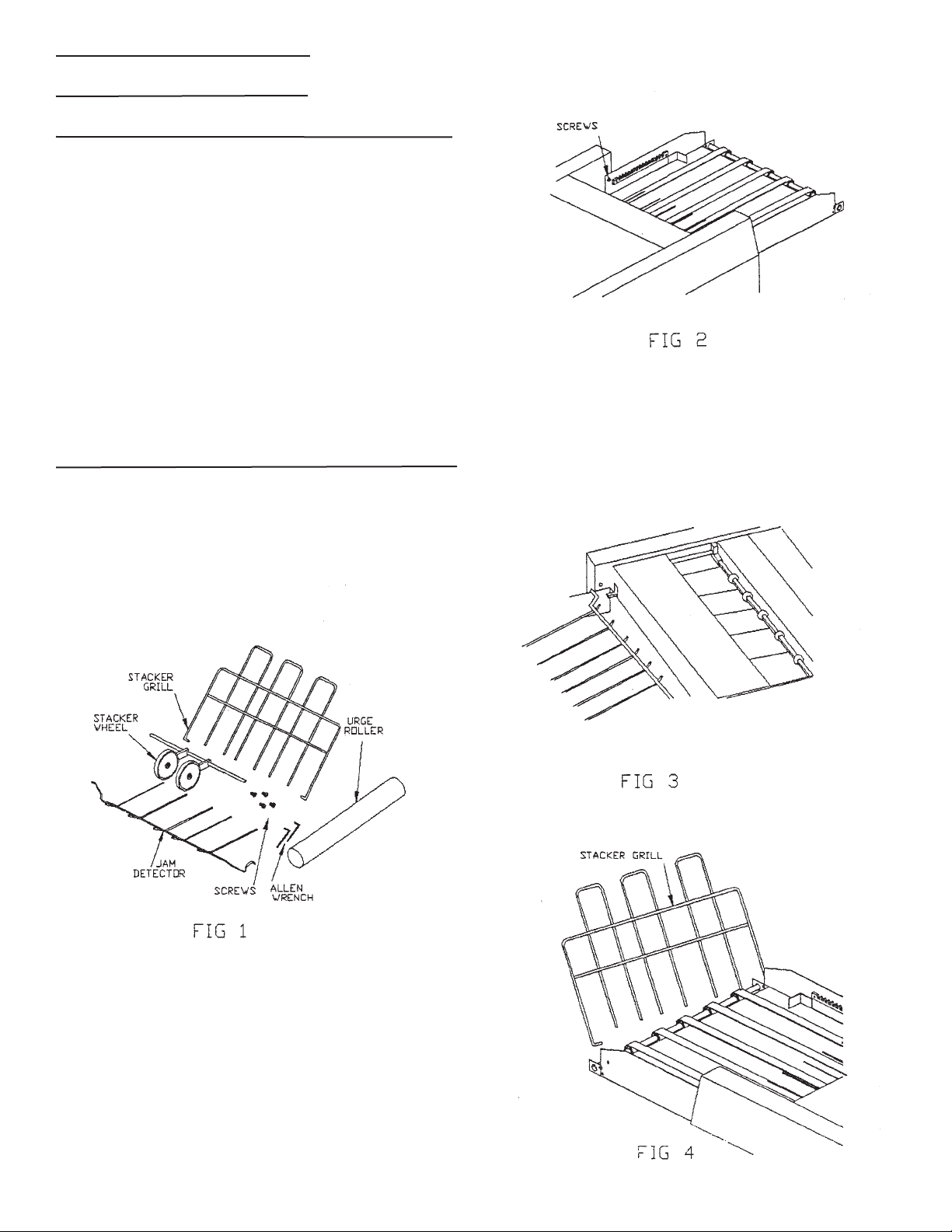
1. Remove the contents of the accessory box and compare them
against the photograph below. (Fig. 1)
2. Butt the Stacker up against the Burster to mesh the drive gear.
Align the holes in the Stacker Chassis with the threaded inserts in
the Burster. (Fig. 2)
5. Slip the Stacker Grill into the holes. The Stacker Grill should
be slanted away from the Burster. (Large forward holes) (Fig. 4)
3. Insert all four screws (two (2) on underside of stacker tray)
without tightening them. Once they are all in, tighten with a
medium Phillips screwdriver. (Fig.2)
2
Page 5
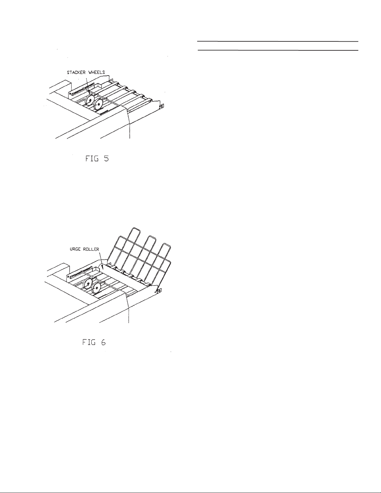
6. Place the stacker wheel assembly on the stacker wheel
adjustment rack. (Fig. 5)
ASSEMBLY INSTRUCTIONS FOR
INFEED BRUSH ASSEMBLY
FOR FD546-40 AND FD546-50 ONLY
Tools Required:
Medium Phillips Screwdriver
Parts Required:
1 - Infeed Brush Assembly
(Packed with Burster)
4 - 6-32 Phillips Pan Head Screws
(Packed in Accessory Box)
1. Unpack the infeed brush assembly and inspectfor damage.
2. Place the infeed brush assembly, with the bar on top to the
infeed end of the burster.
3. Align the holes in the infeed brush assembly with the threaded
holes in the burster side frames.
7. Place urge roller on stacker tray so that it rests on the stacker
grill. (Fig.6)
4. Insert all four screws without tightening them, once they are all
in, tighten them with a medium phillips screwdriver.
3
Page 6
OPERATION
GENERAL
This section describes the controls, features, and normal
operating procedures for the FD 540 Series Burster. This
section also identifies and describes the control devices of the
machines. Familiarity with these devices is very important in
order to operate this machine properly.
SAFETY
The machine has built-in safety devices to protect the operator,
but these devices do not replace good operative practices.
--Do not touch any moving parts while the machine is on.
--Keep fingers, long hair, jewelry and loose clothing away
from any moving parts.
--Refer servicing to qualified personnel.
4
Page 7

CONTROL/FEATURE FUNCTION
On/Off Switch Controls power to the Burster. Provides protection for the
operator and the machine against accidental grounds or
shorts. Indicator lights lets operator know that the power is
on.
Speed Control Varies burster speed.
Start Switch Starts Burster.
Stop Button Stops Burster.
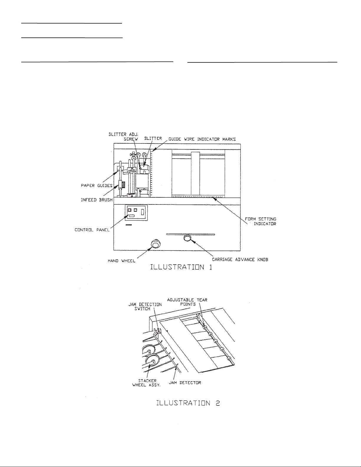
Paper Guides Restrict side to side movement of form while it is entering
the burster.
Infeed Guide Brush Holds forms in place as they are fed over Infeed Table,
Blade Indicator Marks Indicate where Slitter Blades are positioned.
Slitter Adjustment Screws Provide locking positioning of Slitter Boxes.
Handwheel Enables operator positioning of form.
Carriage Adjustment Knob Allow the operator to adjust the position of the Rollers for
proper form length and bursting.
5
Page 8

CONTROL/FEATURE FUNCTION
Guide Wire Indicator Marks Indicates where the Guide wires are withing the
machine
Form Setting Indicator Enables the operator to quickly adjust the machine to
the proper form length.
Form Length Scale Form length can be measured in order to set the
carriage adjustment.
Adjustable Tear Points Applies pressure at the perforation to begin the burst.
Safety Cover Interlock Switch Cuts power to the speed control when safety cover is
opened. Machine will not run with the cover open.
Jam Detection Switch Cuts power to the motor instantaneously in the event
of a paper jam.
Stacker Wheel Assembly Controls forms coming out of the Burster in the Stacker.
Stacker Wheel Form Length Scale Form length can be measured in order to set the
Stacker Wheel Assembly.
Urge Roller Assembly Controls the vertical stacking of the forms on the
Stacker Grill.
Stacker Grill Provides a surface for the forms to vertically stack.
6
Page 9

FORM SET-UP PROCEDURE
1. Without table, machine should be positioned on an ordinary
table with the Slitter Unit overhanging the edge. This will allow
the paper edge trim to be directed into any type of basket placed
under the Slitter Unit.
2. Measure the form length with the form length scale on the
Infeed Cover. (See top photo in Operation, General section for
location of Form Length Scale.)
3. Set the machine for the length of the form by pulling Carriage
Adjustment Knob outward- andr.ota.te it so that the Alignment
Mark on the Feed Roller Cover aligns with the corresponding
form length of the Form Setting Indicator. Push the knob back in.
(Fig. 8)
7. Center the leading edge of the form at the infeed end of the
machine so that the outer edges of the form extend equally
beyond the Guide Wires Indicators on each side, If you find that
the edges come within about 1/4” of the Guide Wires, offset the
form in either direction to avoid this. (Fig. 9)
8. Push the paper guides so that they are approximately 1/16”
from the edge of form.
4. Push the paper guides apart.
5.Thread the form under the infeed rod, over the
paper table and under the iinfeed brush.
6. Lightly press the infeed brush so that it rests lightly on the
form. (Fig. 9)
NOTE: For Models with slitters or tractors see Fig. 14.
9. Using the Handwheel, guide the form thru until the Snap
Roller grabs the form. (Fig. 10)
7
Page 10

10. If necessary, readjust the position of the Feed
Roller Carriage so that the form starts to burst when the
perforation is just under the Tear Bar.
NOTE: The Tear Points can be moved to allow the operator to
position them at any location along the Tear Bar. The
Tear Points should be set between the perforations
that run the length of the form. (Fig. 11)The Tear Bar
height is adjustable to accommodate the characteristics
of various forms. To adjust the height, the tear bar must
be pushed to compress the spring and lifted out. Then
rotate 180 degrees (turned over) and replace making
sure that the square end of the bar locks in the
brackets. Lower position is normal operation, #2313-up.
(Fig. 12)
11. Close safety cover. Machine is now ready to Burst.
Press start button and readjust machine speed to the
fastest, yet smoothest Burst.
8
Page 11

SET-UP PROCEDURES FOR
MODELS WITH SLITTERS
FOLLOW FORM SET-UP PROCEDURES 1 THRU 9 AND
PROCEED AS FOLLOWS.
SET-UP PROCEDURES FOR
MODELS WITH SLITTERS AND
TRACTORS
1. Noting the Blade Indicator Marks on the Upper Guide table so
the Edge Slitters, position each Edge Slitter in from of the corner
edges of the form to trim edges as desired. (Fig. 13)
2. Lock the Edge Slitters in place by tightening the Thumb screws
clockwise.
FOLLOW FORM SET-UP PROCEDURES 1 THRU 8 AND
PROCEED AND FOLLOWS.
1. Unlock Tractors and open Tractor Gates.
2. Place the form on the Feed Pins. (Fig, 14)
3. While rotating the Burster Handwheel clockwise,
slowly push the form through the Edge Slitters.
NOTE: To thread paper you do not wish to slit, push the Edge
Slitters apart and out of the way. To use Center Slitter, position
Slitters where cut is desired, tighten thumbscrew and set
screws.
4. Continue with steps 10 thru 11 in the Forms Set-Up
Procedures Section.
NOTE: Do not stretch the form too tightly between
the pins; the pins should be entered in the margin holes.
3. Close Tractor Gates and lock by pushing the lever forward
4. Continue with steps 9 through 11 in the Forms Set-up
Procedures section.
9
Page 12

10
Page 13

IMPRINTER, SLITTERS AND
TRACTORS SET-UP PROCEDURES
NOTE: It is recommended that forms or checks fed into
imprinter should be last form first, right side up.
1. Slide Paper Guides to either side of the Guide Bar.
2. Thread the form under the Guide Bar,
3. Position the Tractors to the proper form width by lifting the Levers
on the side on the Tractors. Raise the Tractor Gates and sliding the
tractors to the proper width. Place the form on the Feed Pins as
shown in Fig. 14. Close the Tractor gates and secure their position
by pushing the Locking Levers down.
NOTE: Do not stretch the form to tightly between the pins; the pins
should be centered in the margin holes. Align top of first form with
top of Tractor,
4. Draw a horizontal line through the desired Signature area on the
last form.
5. Loosen the Setscrews on the Ink Roller (If the Setscrews are not
in plain view, use the Handwheel to bring them into view). Slide the
Ink Roller well away from the Signature area on the Check.
6. Loosen Setscrews on Platen Cylinder (if the Setscrews are not
in plain view, use the Handwheel to bring them into plain view).
Horizontally align the Platen Cylinder with the Signature area on
the Check. Tighten Set Screws. (Fig. 15)
7. Loosen Setscrews in Imprint Cylinder (if the Setscrews are not
in plain view, use the Handwheel to bring them into plain view).
8. Install the Signature Saddle into Print Cylinder by rotating the
Knurled Sleeve until both cutouts are aligned with the pins. Drop
in Signature Saddle and rotate Sleeve to lock position. Slide
Print Cylinder to Signature area. (Fig. 16)
NOTE: If using 3 1/2”; Check use two (2) Saddles, If using 7”
Check use one (1) Saddle.
9. With the Print Cylinder Setscrews toward you; using the
Handwheel, align the Signature Saddle .with the horizontal line
on the Check. (Fig. 17). Tighten Setscrews.
11
Page 14

10. Turn Handwheel until Signature is printed on second check.
OPERATING HINTS
11. Located at the right end of the Imprint Cylinder shaft is the
timing collar. Loosen setscrew and align timing mark on Collar
with arrow on right side of machine. This will be your timing
mark.
12. Position Ink Roller in front of Signature Saddle and tighten
set screws.
13. Adjust the tension of the Ink Roller so that it lightly
touches Signature Saddle, by rotating Ink Roller Adjustment
Thumbscrews uniformally. (Fig. 19)
1. Some paper has a natural curve. Sometimes thia curve tends
to catch air and sail. If this occurs try running them upside down.
2. Perforations vary in strength. If the forms are bursting
hard, tearing or breaking behind the tear bar, vary the Carriage
Adjusting Knob setting up to 1/2” ahead or behind the actual form
size setting.
3. Multiple part forms with hard-glued edge can be burst by
positioning the tear point over the glued edge.
4. The Stacker Wheels should not stop the form until it clears the
Snap Rollers.
5. Carbonized forms will generally stack better when ran with the
coated side up.
7” FORMS IMPRINTING SET-UP
1. 7” Forms Imprinting Set Up is the same asfor 3-1/2” forms,
except that one saddle is used instead of two.
2. Set the form length adjustment to “7” w/imprint”.
3. Reposition the tear bar to the “7” w/imprint setting”.
4. To assure that the Burster rollers are timed, rotate the
forms advance handwheel until the “timing marks” appear
simultaneously through the slots in each roller cover. (See Fig.
20).
14. To load checks after burster has been set up;
A. With handwheel, turn forward until timing mark of collar (step
11) aligns with arrow on side of machine.
B. Place forms on tractors so leading edge is at top of tractors.
C., Rotate forms forward until they enter into the burster, set
speed and turn on.
12
Page 15

TROUBLESHOOTING
Feeding, Bursting, and Stacking problems ar usually
due to improper adjustment of the machine to the forms
or due to non-standaTd or defective. forms. Refer to the
table below for typical problems.
Most problems fall into. one of three categories:
Electrical, Mechanical, or Form Flow. Electrical troubles
are usually obvious in that the machine will not run or
respond in the normal manner to its
controls. Mechanical problems are usually
accompanied by noise, slippage, tearing, or binds. If
aform flow problem is present, jamming, misstacking
or intermittent form damage will occur. The problems
should be diagnosed to one of the three categories
before proceeding to pinpoint the problem, The
best approach is a logical elimination of possible
malfunctions.
SYMPTOM PROBABLE CAUSE
Burster will not run. Line plug loose or pulled out’ Last Form Switch
Activated. (No Forms in Tractors). Switch off. Safety cover not
completely closed. Jam detector not activating Jam Detection
Switch.
Forms creep to one side. Infeed guides not set properly. Tension not uniform across the
roller. Edge of form not under roller.
Burster stalls tears forms. Tear point too high Burster not running fast enough. Feed
Roller carriage not positioned properly. Tough Form
perforations.
Improper Stacking Stacker wheels too close to outfeed of Burster. Stacker wheels
too far away from outfeed of Burster. Wheels not directly over
belts. Wheels not spinning freely. Edge of form not under roller.
Stacker Grill not properly adjusted.
Poor Slitting Slitter Blades improperly adjusted. Worn Blades.
Edge Slitters difficult to slide. Foreign material on Shafts (dirt, dust, grease). Burrs, marks
on Shafts. Material buildup in Slitter Hubs.
Stacker does not run but Burster does. Loose setscrew Broken belt.
Rollers do not rotate while motor is running. Broken Drive belt.
Loose Setscrews; on sprocket.
Broken chain.
Feed Roller Carriage will not advance. Loose Setscrew on Handwheel. Obstruction on rack. Pin
missing to drive gear.
Not Bursting properly Carriage not properly positioned. Incorrect roller tension.
13
Page 16

SYMPTOM PROBABLE CAUSE
Large variation in trim accuracy. Upper/Lower Side Guides too loose/tight.
Paper pack not centered to Slitter
Infeed. Brush Tension to tight.
Form pull out to tractors. Incorrect Burster roller timing.
Incorrect Tear Bar setting.
Insufficient Feed roller tension.
Uneven Inking. Ink Roll not adjusted uniformly.
Ink Roll dried up, or not turning freely.
Signature patch worn or installed improperly.
Uneven Signature Position. Forms not in Tractors.
Print Cylinder timing incorrect.
Incorrect form size,
Signature patch position(s) incorrect.
Check roller timing-imprint position.
Set infeed tension higher.
Clean rollers.
Incorrect Counting. Code Mode Switch in wrong position.
Counter not cleared to zero.
14
Page 17

 Loading...