

Page 1

FD 4400
High-Volume
EDITION
Page 2

Blank
Page 3

Burster Unpack and Assembly
Pump Installation
Controls
Length Set-up Procedure
Squaring Feed Table
Vacuum Feed Sheet Separator
Horizontal Separator Adjustment
Feeding Paper
Bleeder Valve (Vacuum Adjustment)
TROUBLESHOOTING
Page 4

Page 5
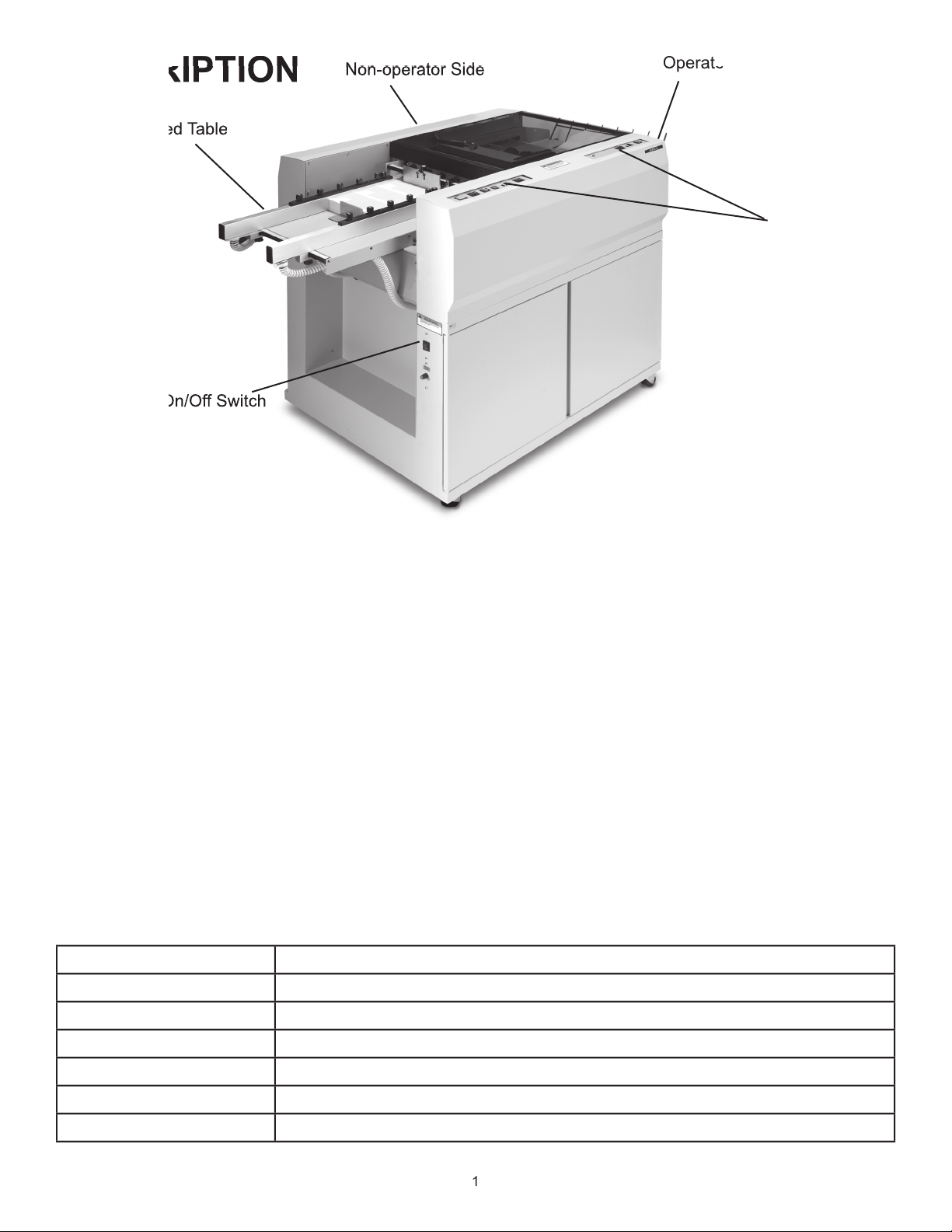
Air-Feed Table
The FD 4400 High-Volume Cut-Sheet Burster
A bottom-feed air system is utilized to allow operators to continually load forms to maximize effi ciency and
throughput.
The Conveyor
The o
Variable, up to 30,000/hour (11”)
42” H x 33” W x 64.5” - 72” L
Weight:
Approx. 500 lbs.
Page 6

Assembly
Lifting should not be attempted by less
than four people.
wooden pallet. Remove cardboard box.
4. Remove (4) foam blocks.
table.
9. Add 1/4-20 x 1 1/2 locating screws (included),
to underside of table, screwing up into burster
frame.
t
wo people should unpack and install
the base.
the rear and the vacuum is toward the front of the
the
to the right side of the base
th the mounting holes in the fl oor and
fans as shown in Fig. 3. Insert mounting bolts and
Vacuum
Page 7

Vacuum Hose
feed thru the
of
the burster).
feed up
of
the burster).
four
screws
A
table into place
the metal fi ngers under the blind roller and
4. Reset the table on infeed cover and align the holes
the cover
Page 8

-deck
screws
Page 9

Turns burster on and off
Jog Switch
Advances forms forward or backward at infeed and outfeed
4
4
2
Page 10

Length Set-up Procedure
Length Scale
Alignment Mark
2
to burst when perforation is just under tear points.
to position them at any location along tear bar. Tear
vertically along the length of the form. (Illust. 1)
Page 11

Vacuum Feed Sheet Separator
The sheet separator will need adjusting for the
weight of paper you are bursting. Ideal adjustment
will feed only one sheet without marking the paper
to the condition of the paper and the environmental
Adjustment Procedure
the sucker
wheel.
feature allows for quick and easy adjustment if
feeder table (Fig 14).
The rear scale will line up with the inside edge of the
4. Position the operator side guide so it is just touching
the sheet but not pushing it. The side guide must be
tuning the overall squareness.
Adjusting Knob
4
Table
Page 12

fl oat the bottom of the paper stack approximately
from the separator.
4. The vacuum advance knob is located on the side
4. Adjust separator assembly so that the plate is 1/16”
forward of the 12 o’clock position, measure from the
feed side of the plate.
Vacuum Advance
Air Blast Control
Air Blast
New Pic
Page 13

Turn the speed control to ½ or full speed. Place
your thumb on the back of the stack to keep paper
from feeding. Press the power button, the sucker
wheel will start to turn. Reduce the
thumb to feed only 3 to 4 sheets. Press your thumb
There is a bleeder valve on the vacuum pump, (Fig 20),
which allows for vacuum adjustment from completely
valve are half open for 20# stock, and closed for 80#
this can be opened slightly to “relieve” some of the
vacuum and stop the double feeding.
20
Tips
two stop buttons. Opening safety cover or lifting jam
thumbwheel is turned down.
4. Perforations vary in strength. If forms are bursting
Page 14

to a non-standard or defective form.
TROUBLE
Are the safety covers lowered?
turned on, plugged in, wall
wall outlet has power.
Are outfeed stacker nip rollers
to eliminate curl.
Page 15

forms
Tear bar in high position.
Tear points not adjusted properly
Tough form perforations.
Adjust tear points
Adjust tear points
Won’t burst properly.
Tear point not set correctly.
Tear bar not set correctly.
Adjust tear points
Adjust tear bar position
Tighten setscrew, call for service.
Adjust wheels left or right so they are
Page 16

 Loading...