

Page 1

FD/FE 4040 4’ Conveyor
FD/FE 4060 6’ Conveyor
7/2015
OPERATOR MANUAL
Rev 2
Page 2
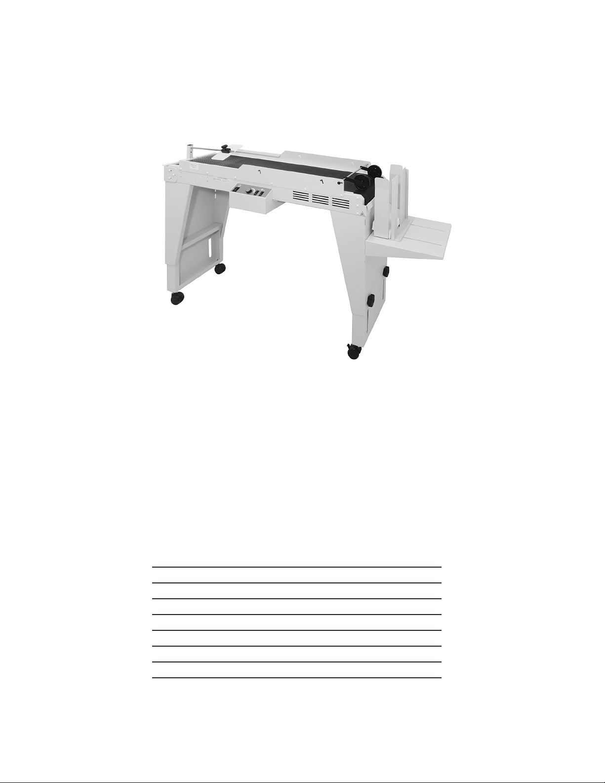
TABLE OF CONTENTS
SPECIFICATIONS 1
UNPACKING 1
ASSEMBLY 2
Mounting Adjustable Legs 2
Control Panel Module (Optional adjustment) 3
Mounting Accessories 4
MOUNTING OPTIONAL D1000 1K DRYER 8
SETUP & OPERATION 9 - 11
Page 3

SPECIFICATIONS
CONVEYOR
POWER FD: 105/120 VAC 50/60 HZ FE: 240 VAC 50/60 HZ
MAIN FUSE
SECONDARY FUSE FD 4040: 3 AMP FD 4040:
POWER CONSUMPTION
CONVEYOR @ MAX SPEED NO LOAD
CONVEYOR @ MAX SPEED NO LOAD W/ ONE
FAN
CONVEYOR @ MAX SPEED NO LOAD W/ BOTH
FANS
CONVEYOR @ MAX SPEED NO LOAD W/ BOTH
FANS AND DRYER
BELT SPEED VARIABLE 30 TO 350 FT PER MINUTE
FAN C.F.M. 170 C.F.M. EACH
HEIGHT ADJUSTABLE 28” TO 35” FLOOR TO TRANSPORT BELT
LENGTH 65”
WIDTH 14”
DROP TRAY
FD 4040: 10 AMP FE 4040: 7 AMP
FD 4060: 15 AMP FE 4060: 10 AMP
FD 4040: .56 AMP FE 4040:
FD 4060: FE 4060:
FD 4040: .76 AMP FE 4040:
FD 4060: FE 4060:
FD 4040: .96 AMP FE 4040:
FD 4060: FE 4060:
FD 4040: 6.19 AMP FE 4040:
FD 4060: FE 4060:
ADJUSTABLE 5.2’, 7.2”, 9.2” & 11.2” TRANSPORT BELT TO STACKING
SURFACE
WEIGHT 130 LBS (INCLUDES ACCESSORIES)
UNPACKING
INSPECT FOR SHIPPING DAMAGE, MISSING PARTS AND PROPER OPERATION. REPORT SHIPPING DAMAGE
TO THE CARRIER IMMEDIATELY. SAVE THE SHIPPING CARTONS AND MATERIALS IN CASE THEY ARE NEEDED
TO FILE A SHIPPING CLAIM OR FOR FUTURE SHIPPING USE.
1. Check the outside of the carton for visible damage. Make note of any damage on the carrier’s receiving report.
2. Open the carton.
3. Carefully remove the carton contents and inspect the unit for paint and structural damage.
4. Carefully check for missing parts. If damage or missing parts are noted, contact your Sales Representative immediately. Save cartons and packing materials. They may be required to substantiate a damage claim or to return a damaged
unit.
1
Page 4
ASSEMBLY
Mounting Adjustable Legs
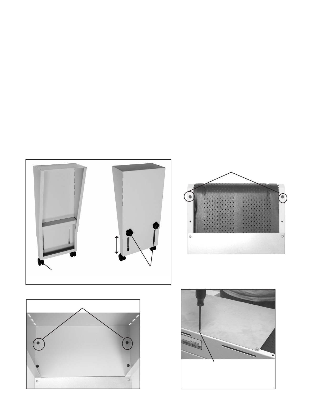
Install 2 swivel casters on each of the leg assemblies (Fig 1 item A). Secure casters with hex nuts.
1.
To pre-adjust leg assemblies to proper length, measure the distance from the oor, to the exit surface of the delivery
2.
device (i.e. printer). Loosen the black hand wheels (Fig 1 item B) and adjust leg assembly until overall length,
including casters, is about 7 inches less than the measurement you just obtained. Tighten hand wheels and repeat
procedure for other leg assembly.
With conveyor laying upside down, install leg assembly. Install two Allen screws to the outer edge of the conveyor
3.
(Fig 2 item C) do not tighten all the way, leave enough space to slide the keyhole, in the top of the leg assembly,
into position (Fig 3 item D). Insert two screws into the two remaining holes, tighten when all screws are in position
(Fig 4). Allen screws are provided in accessory bag.
Assembly Tip (Fig 4): If you have trouble aligning the screw holes in the leg assemblies with the conveyor holes;
loosen the 10 Phillips head screws that secure the bottom plate (Fig 4), to allow the conveyor side frames to ex.
When nished securing leg assemblies to conveyor, be sure to re-tighten these 10 Phillips head screws.
With the legs securely fastened, carefully turn conveyor upright. Note: If conveyor operation direction needs to be
4.
changed, do so before turning upright - see Control Panel Module Optional Adjustment Pg 3.
CAUTION! Two (2) people are required for lifting and turning conveyor.
C
Fig 1
Fig 3
Fig 2
A
D
B
To help align holes, when attaching leg
assemblies, loosen screws that secure
bottom plate.
Fig 4
2
Page 5
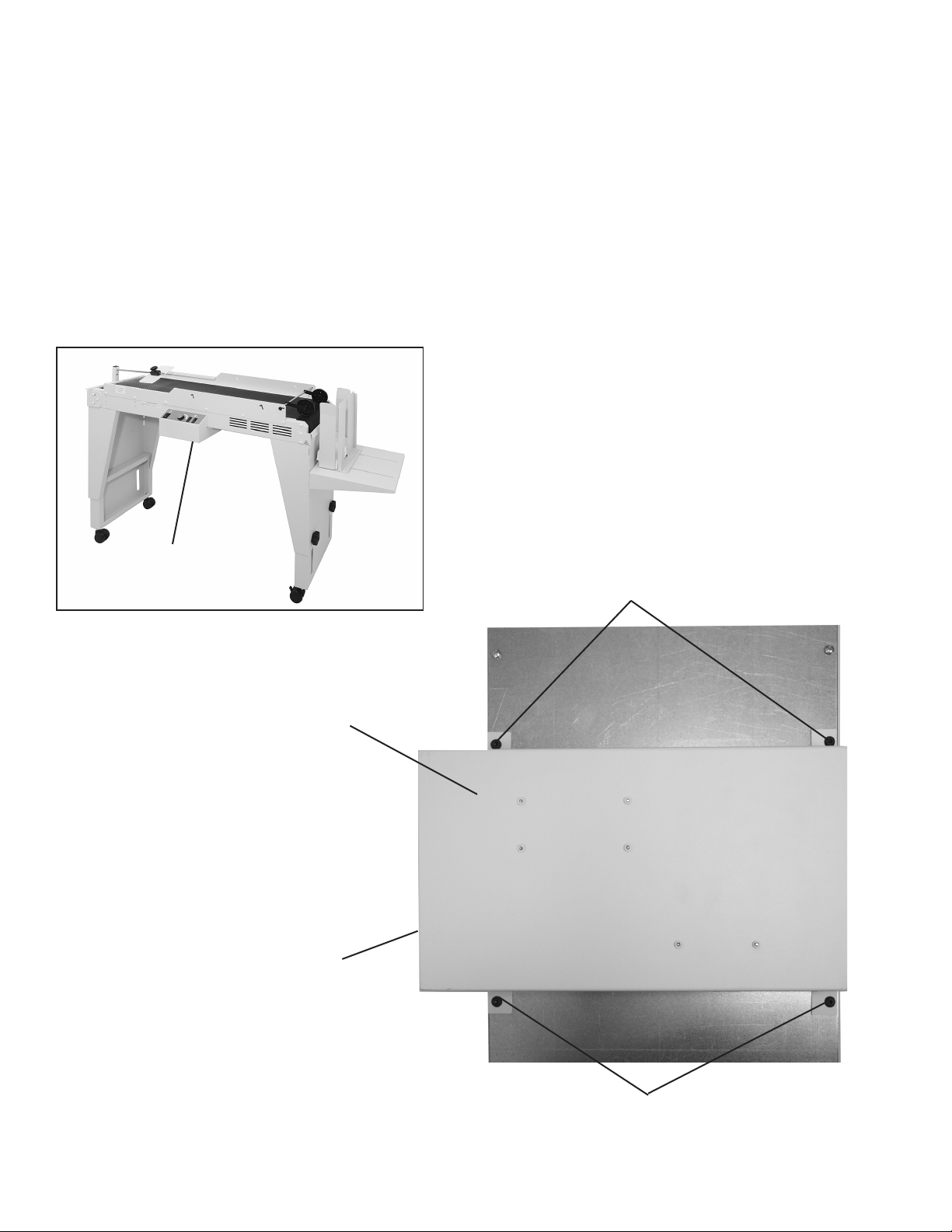
Control Panel Module (Optional adjustment)
If the direction of conveyor needs to be changed, a simple adjustment to the control panel module can be made while
the conveyor is in the upside down position.
Remove the four Phillips head screws that hold the control panel module in place (Fig 5 items A).
1.
Rotate the control panel 180 degrees counterclockwise and reattach with the four screws. No electrical connection
2.
adjustments are needed.
With the legs securely fastened and control panel module mounted properly, carefully turn conveyor upright.
3.
CAUTION! Two (2) people are required for lifting and turning conveyor.
Control Panel Module
Conveyor shown going left to right
Control Panel Module
Front of control panel
module
A
Fig 5
A
3
Page 6

Mounting Accessories
Envelope knockdown bracket assembly (Fig 6): To install, temporarily mount the envelope knockdown post (Fig 6
1
item A) in the down position, as shown below. Use thumb screw and securing plate (Fig 6 items B & C) to attach the
post to the bracket.
B
Fig 6
Mount envelope knockdown assembly onto the in-feed of the conveyor (Fig 7 item D) using 6 each white Phillips
2.
head machine screws provided in accessory bag. NOTE: The suction fans are located at the in-feed of the
conveyor. Loosen knockdown post thumb screw (Fig 6 item B) and rotate post 90 degrees into an upright position
(Fig 7).
Mount the outfeed bracket (Fig 7 item E) to the opposite end of the conveyor using the 4 white phillips head
3.
machine screws. Do not completely tighten screws. Continue to step 4 for bracket adjustment.
D
fans
A
C
E
Fig 7
In-feed
Mounting Screws
Out-feed
4
Page 7

CAUTION! This adjustment is necessary to avoid belt damage and eliminate a potential pinch point for safety.
4.
Insert supplied card stock spacer (Fig 8a item A) between the belt and the out-feed bracket to set the spacing
between the bracket and the belt. Move the bracket in or out until a slight drag is felt on the card stock (Fig 8b
item B) and then tighten mounting screws (Fig 8c) . Remove card stock spacer and rotate belt and roller by hand
(Fig 8d) to ensure clearance at all points on the roller and belt. Readjust if belt contacts bracket.
Fig 8a
Mounting screws
Fig 8c
A
Fig 8b
Ensure clearance between belt and bracket
Fig 8d
B
5
Page 8

Mount the side rails to either side of the conveyor with 6 each white Phillips head machine screws provided in
5.
accessory bag. The taller side goes on the out-feed end (Fig 9 items A & B). Note: If the optional D1000 1K dryer
is going to be attached leave the side rail screws loose for mounting the dryer.
B
A
Fig 9
A
Install threaded end of envelope knock down
6.
rod (Fig 10 item B) into hole of envelope knock
B
down post (Fig 10 item C). Install 1 white Phillips
head screw through post and into threaded
screw
rod. Install envelope knock down guide (Fig 10
item A) onto rod, as shown (Fig 10), and secure
using thumb screw.
C
Warning! Be sure the bottom of the envelope
knock down guide does not rub against the belt
or damage to the belt may result.
Install exit wheel assembly (Fig 11 item A)
7.
between rails of conveyor; align with mounting
holes and secure in place with 2 black
thumbscrews provided. The wheels can be
repositioned anywhere along the rod to meet
your specic needs.
Fig 10
A
Fig 11
6
Page 9

Install adjustable height drop tray (Fig 12 item A) into slots in leg assembly (Fig 11 item B).
8.
Install envelope stop plate (Fig 12 item C) onto drop tray using 2 hand wheel nuts provided (Fig 12 item D).
9.
Place envelope side guides (Fig 12 item E), magnetically mounted, onto drop tray.
10.
E
C
C
B
Fig 12
Attach the mounting bracket (Fig 13 item A) to the conveyor. This bracket is used to secure the conveyor to the
11.
A
table that the delivery device (i.e. printer) sits on. See mounting details supplied with the bracket. Do not attach
bracket to table until correct conveyor height has been determined (see page 9).
A
D
Fig 13
7
Page 10

MOUNTING OPTIONAL D1000 1K DRYER
1. Slide mounting rods through holes in dryer (Fig 14a item A).
2. Loosen side rail screws.
3. Loosen side rails (Fig 9 items A & B pg 6), place dryer and rods between rails of conveyor (Fig 14a item A), align
with mounting slots in high or low position (Fig 14b item B) and secure in place with the 4 white Phillips head
screws supplied. Note: Mounting rods, screws and electric components supplied in dryer box.
4. Connect the dryer’s power cord to the receptacle on the back of the dryer (Fig 15a item C) and on the back of the
control panel module (Fig 15b item D). Note: The dryer receptacle is marked on the back of the control panel
module.
CAUTION! Do NOT connect dryer to a separate power source or dryer damage may result. Connect dryer power
cord only to outlet on conveyor, as shown below.
Fig 14a
Fig 15a
Mounting Rods
C
A
Fig 14b
Fig 15b
B
D
8
Page 11

SETUP & OPERATION
Place completed conveyor assembly behind delivery device (i.e. printer) with fans centered on exit end of delivery
1.
device. Attach conveyor mounting bracket to table that the device is sitting on for stability using lag bolts provided,
see mounting details supplied with bracket.
The top of the front guide rail (Fig 16a item A), should be positioned about 1 inch below the exit surface of the
2.
delivery device (i.e. printer). If height adjustment is necessary, have another person support the weight of the
conveyor while you carefully loosen the black hand wheels (Fig 1 item B) and adjust the height of the conveyor leg
assemblies. Retighten to secure in place.
CAUTION! Be careful when performing this procedure. The conveyor is heavy and can cause injury if not properly
supported.
A
Fig 16a - Right angle printer setup Fig 16b - Optional straight-on printer setup
Optional Slide Bar for slow printing speed
If the printer is set at a slow speed, the slide bar (Fig 17a item A) may be needed to feed the envelope onto the
conveyor. Set the slide bar so that the top 1/4 of the envelope rides on the bar (Fig 17b item B). The envelope should
slide across the bar, hit the deector and land on the conveyor in the correct position. To ne tune, move the slide bar
backwards or forwards and adjust the conveyor speed.
A
B
Fig 17a
Fig 17b
9
Page 12

Connect conveyor power cord to a grounded 105/120 VAC, 50/60 Hz electrical source.
3.
Set up delivery device (i.e. printer) for desired media.
4.
The setup of the conveyor (which includes drop tray height, stop plate position, envelope knock down position, belt
5.
speed, and fan combination) is in direct relation to type, size and speed of media being delivered to the conveyor.
Send a test piece of media through delivery device (i.e. printer) to adjust proper distance of envelope knockdown
guide away from exit end of delivery device.
Start (power on) conveyor. Send a few test pieces of media through delivery device. Set conveyor belt speed to
obtain desired gap between pieces of media. Fans can be used to control media movement once it drops onto the
conveyor belt. Set fan controls as desired.
Note: At very low conveyor transport speed settings the transport belt may stall easily, especially when the fans
and/or dryer are being used. Increase the transport speed setting to prevent this condition.
Control Panel
Power Toggle Switch
Speed Control
Fan Toggle Switches
10
Page 13

6. To raise or lower drop tray (Fig 18 item A), insert hooks on drop tray into slots (Fig 18 item B) in leg assembly at
desired height.
7. To move envelope stop plate position (Fig 18 item C), loosen 2 hand wheel nuts (Fig 12 item D), and reposition
stop plate to accommodate the media, then tighten hand wheel nuts.
8. Position envelope side guides (Fig 18 item E), magnetically mounted, at desired location.
9. Send several test pieces of media through delivery device and conveyor to ensure correct set up.
Make adjustments if necessary.
10. The conveyor is now ready for operation.
E
C
B
Fig 18
A
11
Page 14

 Loading...