

Page 1

FD 125
Large-Format Card Cutter
9/2012
OPERATOR MANUAL
Page 2

Page 2
Page 3

Page 3
Table of Contents
SAFETY PRECAUTIONS ........................................................................................................................................................ 4
Introduction ........................................................................................................................................................................ 5
Specifications ...................................................................................................................................................................... 5
Accessories ......................................................................................................................................................................... 5
Major Components and Assemblies ................................................................................................................................... 6
Control Panel ...................................................................................................................................................................... 8
Installation .......................................................................................................................................................................... 9
Setting Up Procedure ......................................................................................................................................................... 9
The Job selection .............................................................................................................................................................. 11
Registration Mark Position ............................................................................................................................................... 15
Selecting a job ................................................................................................................................................................... 15
Batch Count function ........................................................................................................................................................ 16
User Define Job ................................................................................................................................................................. 17
Cut mark ........................................................................................................................................................................... 18
Turbo and normal Mode .................................................................................................................................................. 18
Paper weight ..................................................................................................................................................................... 18
Reset Counter ................................................................................................................................................................... 19
Clear Jam .......................................................................................................................................................................... 19
Troubleshooting ............................................................................................................................................................... 20
Optional Slitter Cassette ................................................................................................................................................... 20
Optional Conveyor ............................................................................................................................................................ 21
Page 4
Page 4
SAFETY PRECAUTIONS
Always pull the power supply plug out of its outlet before removing jammed
paper.
Do not use supply voltage other than the specified voltage.
Do not insert pins, wire or other foreign objects into the machine. Do not allow
any liquid to get into the machine through its openings or gaps in its structure.
Do not modify the machine. Do not remove any of the covers from the machine..
Keep this unit and the power cord away from heaters and heater vents. Excessive heat could
melt the cover or power cord covering, and result in a fire or an electrical shock.
Do not put fingers inside during operation.
Keep away long hair, ties, jewelry and loose clothing.
Install this unit on a level, stable stand or floor, with sufficient space around it.
Do not install this unit in a location where there is excessive humidity or where contact with
water is possible.
Disconnect the power plug from the power outlet before attempting to move this unit. Failure to
do so could result in power cord damage, a fire or an electrical shock.
Always observe the cautions and warnings given below to prevent personal injury or property damage.
Page 5
Page 5
INTRODUCTION
Paper Size
LT, LG, LD, 12 x 18 and 13 x 19
Paper Weight
120 ~ 350 gsm
Feeder Capacity
120 sheets (300gsm)
Receiving Tray
250 business Card x 3
Speed
Up to 240 business cards/min
Based on 55x90mm in A3
Accuracy
± 0.2 mm
Dimension -- With Conveyor
W/O Conveyor
98.5 X 53.5 X 101.5CM (38.8x21.1 x 40”)
48.5 X 53.5 X 101.5CM (19.1 x 21.1 x 40”)
Net Weight –With Conveyor
W/O Conveyor
70.8Kgs ( 156 lbs)
61.2Kgs (135 lbs)
Power
110/220V Selectable, 50/60Hz, 1.2A
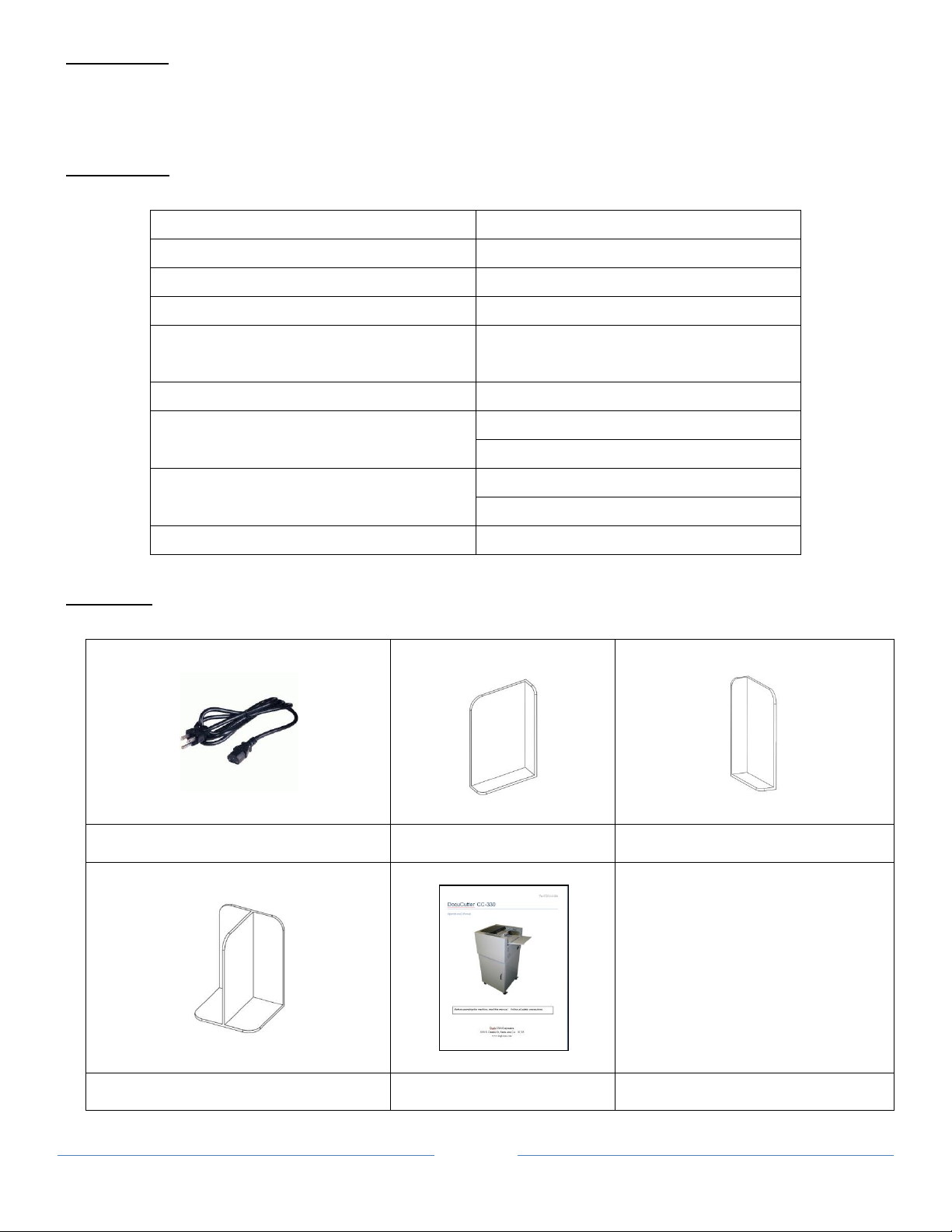
Power Cord
Right Stacking Guide
Left Stacking Guide
Center Stacking Guides X 2
Operation Manual
The FD 125 is designed to easily and accurately cut business cards, photos and postcard cutting in one pass.
SPECIFICATIONS
ACCESSORIES
Make sure all accessories provided with the machine.
Page 6
Page 6
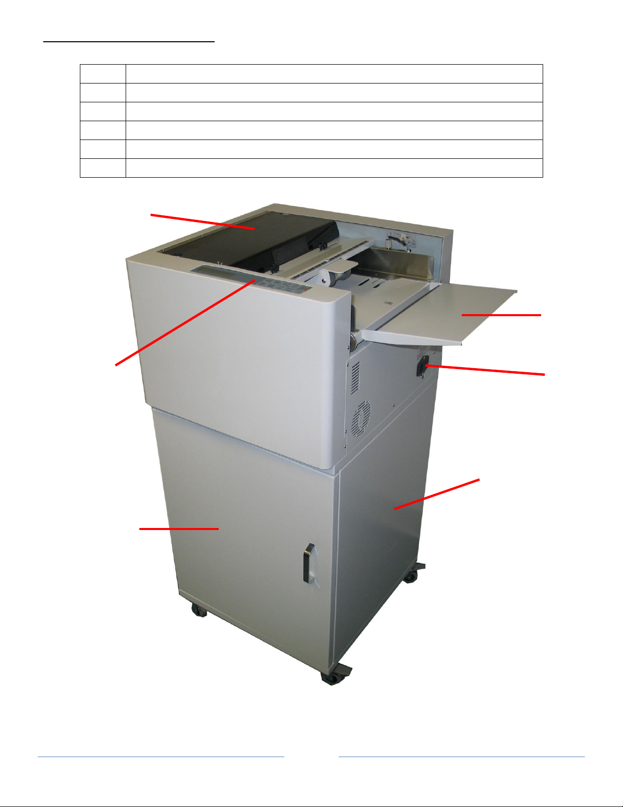
MAJOR COMPONENTS AND ASSEMBLIES
1
Power Switch
2
Control Panel
3
Extended Tray
4
Top Cover
5
Waste Compartment Door
6
Machine Stand
1
3
4
5
2
6
Page 7
Page 7
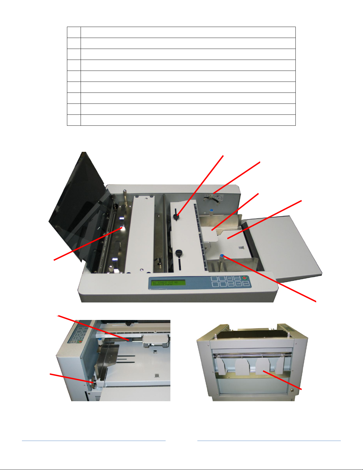
7
Stack Tray
8
Auxiliary Roller
9
Side Guide Adjustment Knob
10
Feed Tray Pressure Adjustment
11
Feed Rollers Adjustment Knob
12
Feed Rollers
13
Slitter Cassette
14
Slitting Registration Adjustment
15
Stacking Guides
7
8
12
9
13
11
10
14
15
Page 8

Page 8
CONTROL PANEL
Keys
Function
Start and Stop the cutter
Change job
Toggle between “Normal Mode” and “Turbo Mode” (Paper Weight Setting Mode)
Select batch count
Pre-feed (Mark Reader Calibration Mode)
Jog forward
Confirm job and batch count setting.
Jog backward
Reset counter (use with “RESET” button simultaneously)
Save settings
Hold (4s) paper weight setting mode
Reset counter (use with “ENTER” Button simultaneously)
Enter program mode
Change paper weight
Set top margin
Set finished length
Increment settings by 0.1 mm when pressed.
Decrement settings by 0.1mm when pressed (Mark Reader Calibration Mode).
Page 9

Page 9
INSTALLATION
on the stand to the holes on the base plate of the machine.
Stack Tray
Power Cord
1
To set the width of paper, loosen thumbscrew knob on
the side guide and slide to position. Use scales as
reference point.
2
Fan paper before loading. This will reduce static and
toner adhesion due to printing. For best result, the
paper stack should be flat.
Thumbscrew
Scales
guides
Pins
1. CUTTER INSTALLATION
Note: No tool is required for installation.
Stand
Place the machine on the stand. Make sure to align the pins
The door of the stand should face the operator side.
Place the left guide, center guides and right guide as shown.
Left
guide
Right
guide
Use caution when plugging in power cord. Attach power cord
to the machine and plug the other end into the wall outlet.
SETTING UP PROCEDURE
Center
knobs
Paper feed guides
Page 10

Page 10
3
Push the feed tray down and load the paper. Readjust
paper guides if needed.
4
Adjust tray pressure. For thinner paper, the number
should be higher. For heavier paper the number should
be lower.
5
Use slitter registration adjustment knob to compensate
for printing registration. The knob will allow ± 2mm of
6
7
Adjust feed rollers so they are about 0.5” away from the
edge on each side of the paper.
adjustment left and right.
Auxiliary roller is for hard-to-feed paper. To use auxiliary
roller, load paper, then push the rollers down onto paper.
Page 11

Page 11
JOB SELECTION
Slitters
Slit Size
Gutter Size
Number of rows
Default Size
Standard Slitter
3.5”
0.25” 3 3.5”
8.5” to 11”
None 1 11”
4” to 6”
0.25” 2 6”
Layouts
Job #
Applications
Display
Paper Size
Finished Size
Layouts
Gutter
Margin
Slitters
A
1
Full Bleed
Business Cards
Business
Card
12”X18”
2” x3.5”
24 up
0.2 in
(5.08 mm)
0.35”
(8.9 mm)
Standard Slitter
B 2 Business card
Business
Card
12”X17”
2” x3.5”
24 up
None
0.75”
(19.1 mm)
Standard Slitter
C 3 Brochure
Brochure
12”X18”
8.5” x 11”
2 up
0.25 in
(6.35 mm)
0.5”
(12.7 mm)
(11 in.)
D
Insert/Greeting
Cards
12”X18”
3.5” x 8.5”
6 up
0.25 in
(6.35 mm)
0.5”
(12.7 mm)
Standard Slitter
E 4 Photo
Photo
12”X18”
8” x 10”
2 up
1.25 in
(31.75 mm)
0.5”
(12.7 mm)
(10 in.)
F
Insert/Greeting
Cards
12”X18”
3.5” x 8”
6 up
1.25 in
(31.75 mm)
0.5”
(12.7 mm)
Standard Slitter
G 5 Postcard
Postcard
12”X18”
5.5” x 8.5”
3 up
0.375 in
(9.525 mm)
0.5”
(12.7 mm)
(8.5 in.)
H 6 Postcard
Postcard
12”X18”
5” x 7”
4 up
3.25 in
(82.55 mm)
0.5”
(12.7 mm)
(5 in.)
I 7 Postcard/Photo
Postcard
13”X19”
4” x 6
8 up
0.5 in
(12.7 mm)
0.5”
(12.7 mm)
(6 in.)
J
8-13
Custom
Program
Postcard
(Program)
12”x18”
3.5”x5”
9 up
0.875 in
(22.2 mm)
1.00”
(25.4 mm)
Standard Slitter
K
Brochure
12”X18”
11” x 17”
1 up
None
0.75”
(19.1 mm)
(11 in.)
L
Postcard
13”X19”
6” x 9”
4 up
0.25 in
(6.35 mm)
0.5”
(12.7 mm)
(6 in.)
The FD 125 offers 7 different programmed jobs from (1 to 7) and 6 programmable jobs (8 to 13).
The standard cassette has a slit size of 3.5” x 3 rows for business cards. Optional cassettes are available.
See below to select the proper slitter and program for your application.
Slitters
Optional Cassette 1
Optional Cassette 2
Applications
Option Slitter 1
Option Slitter 1
Option Slitter 1
Option Slitter 2
Option Slitter 2
Option Slitter 1
Option Slitter 2
Page 12

Page 12
Job Layout
A B
C D
Page 13

Page 13
E F
G H
Page 14

Page 14
I J
K L
Page 15

Page 15
REGISTRATION MARK POSITION
Actions
Display Example
1
Turn on the power. Previous job will appear.
2
Press
01 → 02 → 03 → 04 … 13
3
Press to select job
4
Press to start operation.
#01BUSINESS CARD
NM 2”x3.5” W/G 23
#04 PHOTO
NM 8”x10 W/G 23
#04 PHOTO
NM 8”x10 W/G 23
#04 PHOTO
NM 8”x10 W/G 23
1st Cut
Margin
Center
Feed
Registration mark will compensate for print shifting. See below for registration mark position.
SELECTING A JOB
until the desired job is displayed.
Page 16

Page 16
BATCH COUNT FUNCTION
Actions
Display Example
1
Press
appears. The batch count will increment by 10 every time
Batch → 10 → 20 → 30 → 40 → 50
2
Press to select batch count.
3
Press to start operation.
#04 PHOTO
NM 8”x10 W/G 23
#04 PHOTO
NM 8”x10 W/G 50
#04 PHOTO
NM 8”x10 W/G 50
Batch count function is used to automatically stop the machine after a set number of sheets has been fed.
until the desired batch count number
the button is pressed. Set “OFF” for no batch count.
Page 17

Page 17
Actions
Display Examples
1
Turn on the power. Previous job will appear.
2
Press
01 → 02 → 03 → 04 … 13
3
Press to select job.
4
Hold for 4 seconds. “Edit” will appear indicating
5
Hold and press to increment or to
6
Hold and press to increment or to
7
Hold and press to increment or to
8
Press to save settings.
#10L000.0M00.0G00.0
NM 89
#10L000.0M00.0G00.0
(E) 89
#10L000.0M00.0G00.0
(E) 89
#10L127.0M00.0G00.0
(E) 89
#10L127.0M12.7G00.0
(E) 89
#10L127.0M12.7G06.0
(E) 89
#10L127.0M12.7G06.0
NM 89
#04 PHOTO
NM 8”x10” W/G 50
USER DEFINED JOBS
Only jobs #8 – 13 can be programmed.
until the desired job is displayed.
machine is in “Program Mode”.
decrement change to finished length in mm.
decrement change to top margin in mm
decrement change to gutter length in mm
Page 18

Page 18
CUT MARK
Setting
Paper Weight
1, 2
120 – 210 (gsm)
3
211 – 300 (gsm)
4, 5
301 – 350 (gsm) (Normal Mode)
The purpose of the cut mark is to compensate horizontal cut due to image shifting during printing.
Hold and press to enable or disable cut mark. This will toggle “M” for mark and “NM” for no mark on the
display.
TURBO AND NORMAL MODE
1. Hold for 4 seconds.
2. Press to select “Normal Mode” or “Turbo Mode (Default)”.
3. Press to save settings.
# Paper weight above 300 gsm set it to “Normal Mode”
PAPER WEIGHT
Adjust paper weight settings if paper is skewing or misfeeding.Set 1 or 2 for lighter paper and 4 or 5 for heavier paper.
1. Hold for 4 seconds.
2. Press to select settings 1-5. Use table below for references.
3. Press to save settings.
Page 19

Page 19
RESET COUNTER
Hold and simultaneously to reset counter to 0.
CLEAR JAM
If a jam occurs in the machine follow these steps to clear it.
1. Press and pull out jammed paper toward feeding tray.
2. Press to move the jammed piece toward the exit.
3. If necessary, depending on location of the jam, open the corresponding cover or covers. If jam persists, refer to
“Error Message and Trouble Shooting” page 20.
4. After clearing the jam, press to clear all errors.
Page 20

Page 20
TROUBLESHOOTING
Error
Troubleshooting
Out of paper
1. Adjust the feed tray tension
jam sensor 2
1. Remove the paper jam by pulling toward stacking tray.
2. Adjust the feed hopper tension, if double feed happens
jam sensor 3
1. Use JOG key to clear the jam
2. Adjust feed hopper tension, if double feed happens
check top cover
Put the top cover in position
check rear cover
Put the rear cover in position
Call for service
Error message cannot reset
1. Lift Top Cover
4. Replace with the desired slitter cassette.
turning them clockwise.
Thumbscrews
Lift Handles
Disfeed
FinishĞĚ cardƐ not clean and neat
>ŽĂĚĨeed tray
2. Side guideƐ too tight. Adjust side guideƐ.
3. Fan the paper and reload the paper into ĨĞĞĚƚƌĂLJ
Check covers and ĐŚĞĐŬĨŽƌpaper jam
OPTIONAL SLITTER CASSETTE
Optional slitters enable the &ϭϮϱ to have more range of applications. Follow the stepƐ below to replace optional slitter
cassette.
2. Remove thumbscrewƐ by turning counter-clockwise on
both sideƐ of the slitter cassette.
3. Using both hands, lift ŽƵƚthe slitter cassette.
5. Secure the slitter cassette with the thumbscrewƐ by
Page 21

Page 21
OPTIONAL CONVEYOR
1 x Conveyor
1 x Ramp
1 x Stacking Rollers Assembly
1 x Interface Cable
1 x Stand Support
4 x Studs
4 x Socket Cap Screws (M6x12)
6 x Lock Washers (M6)
4 X Shoulder Washers
4 x Machine Screws (M4 x 12)
2 x Spacer
2 x Machine Screws (M5 x 35)
2 X Hex Bolt (M6 x 30)
4 x Washers (M6)
2 X Hex Nuts (M6)
2 Thumbscrews (M4 x 12)
Accessories List
Page 22

Page 22
2. Remove the chrome bracket.
3. Install the 4 studs as shown using 4 Socket Cap Screws
(M6x12) and 4 Lock Washers (M6).
4. Hook the conveyor onto the studs.
5. Use 2 spacers and Machine Screws (M5 x 35) to secure
the conveyor on the left and right side located below the
conveyor.
6. Plug interface cable to conveyor and machine.
Side Covers
Chrome Bracket
Shoulder Washers
Left Side Spacer
Right Side Spacer
1. Remove the side coversĂŶĚŵĂŐŶĞƚŝĐƐƚĂĐŬŝŶŐŐƵŝĚĞƐ.
7. Fasten 4 Machine Screws (M4 x 12) and 4 shoulder
washers ƚŽ the ŽƉƉŽƐŝƚĞend of the conveyor.
Page 23

Page 23
8. Install the ramp using the key holes.
9. Install Stack Rollers assembly using 2 thumbscrews as
shown onto conveyor rails. Adjust roller distance
depending on paper finish size for better stacking.
10. Install stand support using 2 Hex Bolt (M6 x 30), 4
washers (M6), 2 Lock Washer (M6) and 2 Nuts (M6) and
secure stand support to the stand.
Conveyor Rails
Thumbscrews
 Loading...