

Other Service and Repair
All other service and repairs should only be
done by a qualified repair person or shop. Your
dealer can help you select one or you can send
your Foredom equipment to the Bethel, CT
factory. Factory repairs are done promptly and
at reasonable cost. Send the equipment marked
“Attention: Service Department”. Be sure to
include your street address, email address, and
phone number. The equipment should be
accompanied by a brief note describing the
problem with the equipment. Estimates will
be made upon request.
LIMITED WARRANTY
Foredom warrants the M.PGX Motor (excluding flexible shaft and sheath) and the C.EMGX Dial
Speed Control
purchase, the
after purchase. During the warranty period the defective product will be repaired or
days
replaced without charge or at our option, the purchase price will be refunded. This warranty
does not cover damage caused in transit or by accident, misuse, or ordinary wear.
ALL IMPLIED WARRANTIES, INCLUDING BUT NOT LIMITED TO WARRANTIES OF FITNESS
AND MERCHANTABILITY, ARE HEREBY LIMITED IN DURATION TO THE PERIOD MENTIONED
ABOVE FROM DA
ANY SPECIAL OR CONSEQUENTIAL DAMAGES.
Repair or replacement will be made at our option if the product is returned post-paid to:
All warranty repairs must be done at the factory at the above address. We will not pay any
shipping or transportation charges.
since it is especially sensitive to the pressure and stress variables of each individual operator.
This warranty only covers the original purchaser of the product. Some states do not allow
limitations on how long an implied warranty lasts or the exclusion or limitation of incidental
or consequential damages so the above limitations may not apply to you. This warranty gives
you specific legal rights, and you may also have other rights which vary from state to state.
to be free of defects in material or workmanship for a period of 2 years after
C.FCGX Foot Switch for 1 year after purchase, and the H.9D Handpiece for 90
TE OF PURCHASE, AND WE WILL NOT BE LIABLE OR RESPONSIBLE FOR
The Foredom Electric Company
16 Stony Hill Road
Bethel, CT 06801
The HP76 Duplex Spring is not covered by this warranty
Storage
Store your Foredom power tools in a dry, clean,
dust-free area and out of the reach of children.
Please retain your proof of purchase
for warranty repairs.
Contact Information
For more information on Foredom machines,
handpieces or accessories, contact your local
dealer. When no local dealer is available, write,
call, fax or visit on-line:
The Foredom Electric Company
16 Stony Hill Road, Bethel, CT 06801
Tel.: (203) 792-8622 Fax: (203) 796-7861
Email: customerservice@blackstoneind.com
www.foredom.net
Owner’s Manual
Assembly, Operation and Service for the
PowerGraver® Kit
2-Year Warranty
For Your Own Safety
• Please read this Assembly, Operation, and Service Manual
before operating your Foredom power tool.
• Always wear eye protection while using power tools.
FOREDOM
®
The Foredom Electric Company • Bethel, CT USA 06801 • www.foredom.net
Form 1297 n 6/11
®
FOREDOM
www.foredom.net
Printed in U.S.A.

P
Contents
age
Specifications 2
Safety Instructions 2
The Complete PowerGraver®Kit 3-4
Assembly Instructions 4
Assembly and Adjustment of Handpiece 4-5
Connecting Speed Control and Foot Switch 5
Operation 5
Stroke/Speed Adjustment 5
Installing Accessories
Changing Collets 6
Adjusting Impact of Hammer 6
5-6
Maintenance 6
Routine Cleaning and Lubrication
of Flexible Shaft 6
Replacement of Worn Shaft and Sheath 7
Replacement of Motor Brushes 7
Handpiece Lubrication 7
Other Service and Repair 8
Storage 8
For More Information 8
Limited Warranty 8
Specifications
M.PGX Motor: 125 Volt DC; Ball Bearing
Permanent Magnet Motor, Operable Speed
Range: 500 – 2,800 RPM.
PGX-1 is for use with 115Volt AC.
PGX-2 is for use with 230Volt AC.
C.EMGX Dial Control: Variable speed
manually operated electronic control.
EMGX-1 is for use with 115Volt AC.
EMGX-2 is for use with 230Volt AC.
Shaft/Sheath: Shaft S-93 is 39″ long, and
″ in diameter
.150
S-76N is 36
Optional FCGX Foot Switch: On/Off foot-
operated switching. (115V or 230V AC
Current)
Safety Instructions
Before using your Foredom®power tool,
please read all these safety instructions.
They are for your protection and should always
be followed to reduce the risk of
personal injury or damage to the tool.
• Always wear proper eye and face
protection.
should be worn whenever you operate a
Foredom or any power tool to prevent
serious eye or face injuries.
2
Visit
www.foredom.net
How-To Videos
FOREDOM BASICS
Foredom's National Sales
Manager, walks you through
the "Basics" of using and
maintaining flexible shaft
machines. Downloadable
mini series of .wmv files each
under 5 minutes.
Click to View:
1. Introduction and
Proper Set-up
2. Safety Guidelines
3. Handpieces and
Accessories
4. Maintenance of Shafts
and Sheaths – Grease
and Replace
5. Motor Maintenance–
Remove Dust, Replace
Motor Brushes
. Flexible Neoprene Sheath
1
⁄4″ long.
Safety glasses or face shields
Always make sure your power tool
is unplugged during maintenance!
Replacing Worn Shafts and Sheaths
Shafts and sheaths last longer when they are not
used at sharp angles or loops, since wear occurs at
the points of greatest friction. There is no way to
avoid ultimate wear, and under normal conditions a
flexible shaft machine may require several replacement shafts and sheaths during its lifetime.
To expose the inner shaft follow steps 1, 2, and 3
on the previous page.
Next, remove motor connector
with 1
″ open end or adjustable
wrench.
Motor connector has a
left hand thread and must be
turned clockwise (right)
for removal.
Loosen set screw on the flexible shaft motor
coupling and slide shaft off the motor shaft.
Installation of New Shaft
1. After removing old shaft, loosen set screw on
the new flexible shaft motor coupling and slide
coupling onto motor shaft.
2. Tighten set screw
securely onto the flat of
the motor shaft.
3. Grease shaft prior to
putting on the sheath.
(See lubrication
instructions on page 6.)
4. Slide motor connector back up over the shaft
and tighten to the left (counterclockwise).
5. Slide sheath over flexible shaft with plain fitting directed toward the motor and into the motor
connector. (Each end of the sheath has a metal
fitting. One is plain, the other fits the handpiece.)
6. Adjust the shaft as
shown at top right side
of page and tighten
sheath set screw in
motor connector.
Connector Aligning T
ab
set screw
motor
coupling
Oil Hole
Duplex Spring Cover
motor
shaft
Shaft and Sheath Adjustment:
P
lace the entire unit on
a flat surface with shaft
a
nd sheath extended
Adjust the
straight.
exposed tip of the
flexible shaft at the handpiece
end so that it extends 3/4
the sheath
is done by moving the sheath in or out of the
motor connector. When he correct adjustment is
made, tighten the screw in the motor connector.
, as shown at bottom of page 6. This
″ (19mm) beyond
Replacement of Motor Brushes
New Motor Brush
Motor Brush that
needs replacement
The motor brushes (MP319P) should be
checked for wear periodically. When new, they are
approximately 3/4
when they have worn to 1/4
disconnect motor power cord and unscrew the
brush caps. Be sure that the contour of the
brushes match the contour of the armature when
replacing them. Be sure to replace both motor
brushes even if one of them is less worn than the
other.To remove dirt and dust buildup, when motor
brushes are checked or replaced, compressed air
should be blown through the motor.
″ long. They should be replaced
″. To remove brushes,
Handpiece Lubrication
The H.9D Handpiece requires lubrication
approximately every 40 hours of use. Use oiler
provided to apply
hole located on the barrel of the handpiece under
the palm rest and into the hole on the rear of the
duplex spring connection. To remove palm rest,
loosen set screw.
drops of oil.
two drops of oil into the oiling
Do not apply more than two
Replacement Fuse
The C.EMGX Dial Speed Control may require
CP10543 Replacement Fuse for either 115V AC or
230V AC.
Palm Rest
Impact Adjusting Ring
7
Set Screw
Tool Holder
Chuck Nut
Wrench Flats
Oil Hole

Maintenance Procedures
Always make sure your power tool
is unplugged during maintenance!
It is very important to routinely clean your
Foredom
(NOT the motor), especially in areas that
generate a lot of dust.
Dirt and improper lubrication are the most
common causes of poor operation and
excessive wear.
Always disconnect power tool before
cleaning or servicing.
Note: The M.PGX has permanently
lubricated ball bearings and does not
require additional lubrication.
Routine Cleaning of Motors
Foredom Motors need air circulation through the
motor housing to remove waste heat and cool the
windings. Inlet and outlet slots provide the means
for air flow. However, saw dust and conductive
debris (like metal filings or gold dust) can enter in
through these slots. If not cleaned regularly, dust
can collect, making a bridge between parts,
causing an electrical short.
In high dust environments, Foredom
recommends cleaning the motor every
40 hours of use.
To remove dirt and dust buildup, motor brushes
should be removed, cleaned and replaced, and air
should be blown through the motor.
Routine Cleaning and
Lubrication of Flexible Inner Shaft
The shaft should be checked, wiped clean, and
re-lubricated with grease every 50 hours of use.
With every 200 hours of use, the shaft should be
thoroughly cleaned with solvent and lubricated.
Use Foredom flex shaft grease (p/n MS10006) or
high quality white lubricating grease.
®
Power Tool and lubricate the shaft
Exposing the Inner Shaft
1.Remove handpiece
(see page 4).
2. Loosen set
screw on motor
connector.
3. Slide outer
sheath out of motor
connector and wipe
shaft clean.
4. Apply a very light
coating of lubrication
to shaft starting at the
top and working
downward to about
one inch from the handpiece end. Apply grease
with your finger tip or small brush. Don’t overdo,
apply a light film of grease. Once the machine is
running, the shaft itself will spread the grease. If
too much grease is applied, the excess will work
its way into the handpiece and will make the
handpiece run hot. For this reason, apply a bit
less near the handpiece end of the shaft.
Never operate the motor with the outer
sheath removed from the flexible shaft.
5. Replace and adjust
sheath so that shaft
key tip extends 3/4
(19mm) from sheath.
Retighten the set
screw in motor connector.
6. Clean outside of sheath by wiping with
a cloth.
7. Hang and run the motor for about 10 minutes
before attaching the handpiece to allow enough
time for the grease to warm up, spread and
drain off. Wipe off any excess grease at tip end
of sheath.
8. Re-attach handpiece.
6
″
IMPORTANT!
• Always use dust collection, respirator,
or face mask to prevent inhalation of
dust particles from workpiece
or abrasives.
• Never use or continue to use a graver or
accessory which appears to be damaged.
Inspect each graver for cracks or flaws
before using it.
• Always insert the shank or arbor of an
accessory or mandrel into the collet of
the handpiece as far as possible in order
to provide proper support and tighten the
collet securely.
• Never use excessive side pressures
which may tend to bend or break the
shank or arbor of an accessory. Let the
impact of the hammer do the work.
• Do not stall the motor by jamming or
using excessive pressure on the accessory.
This can result in damage to the motor or
flexible shaft.
• Never operate the motor with the outer
sheath removed from the flexible shaft.
• Always disconnect the power cord
before servicing the motor or removing
the flexible shaft or sheath.
• Never operate your power tool during a
perceptible power decrease. Turn power
tool off and do not use until power is
fully restored.
Accessories
Collets:
HP602 (1/16″),
HP603 (3/32″), 604 (1/8″)
and HP605 (3mm)
Gravers: A-G91 #52 Round
A-G92 #3 Onglette
A-G93 #2 Bevel
A-G94 #40 Flat
10215 Carbide Stylus
10177P Anvil Point
se proper grounding procedures.
• U
should be grounded while in use to protect
the operator from electric shock. The tool is
equipped with an approved 3-conductor cord
and a 3-prong grounding type plug to fit the
proper grounding receptacle. The green (or
green and yellow) conductor in the cord is
the grounding wire. Never connect the green
(or green and yellow) wire to a live terminal.
If your unit is for use on less than 150 volts,
it has a plug that looks like sketch A in the
diagram below. An adapter (sketches B and
C) can be used for connecting plugs as
shown below to 2-prong receptacles. The
green colored rigid ear, lug, etc., extending
from the adapter must be connected to a
permanent ground such as a properly
grounded outlet box.
Some jurisdictions,
This tool
including Canada, prohibit the use of 3 to
2 prong adapters. Where prohibited, they
should not be used.
extension cords that have 3-prong grounding
type plugs and 3-pole receptacles that accept
the tool's plug. Always disconnect the power
cord before servicing the machine. Never use
in an area where flammable vapors are present.
Use only 3-wire
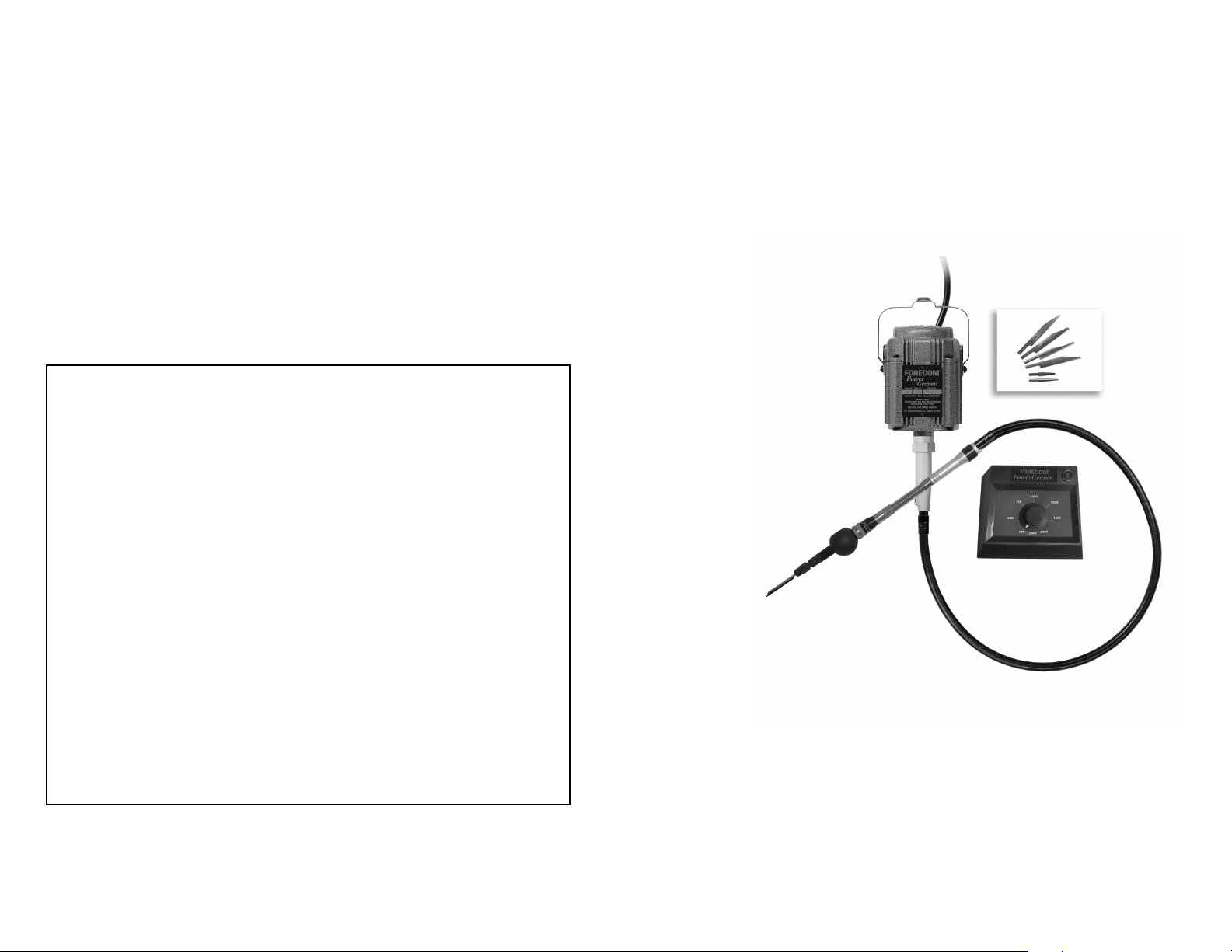
The PowerGraver® Kit
The Foredom®PowerGraver is a complete
power tool used to perform a wide variety of
tasks such as engraving, stone setting, bright
cutting, bead raising, and other applications
requiring the use of a graver or a hammering
effect. Foredom power tools are manufactured to
high standards of precision and with proper use
and regular maintenance will give you years of
trouble-free performance.
The Foredom PowerGraver Kit K.2293
a permanent magnet DC motor, flexible shaft with
neoprene sheath, dedicated handpiece with palm
rest, variable speed dial control, and accessories
listed at left.
3
consists of

The Foredom PowerGraver Kit K.2293
includes collet changing wrenches, handpiece
oil, flexible shaft grease, 32-minute instructional
DVD and booklet.
also
Assembly Instructions
Always make sure your power tool is
unplugged during assembly.
The PowerGraver ships with the shaft and
sheath assembled, however,
be sure that the tip of the shaft extends
″ beyond the end of the sheath. If it
3⁄4
IMPORTANT!
exposed tip of the flexible shaft so that it
extends 3/4
This is done by loosening the set screw in the
motor connector and moving the sheath in or
out of the motor connector. When the correct
adjustment is made, tighten the set screw in
the connector. See photo on bottom of page 6.
Connecting the Handpiece:
Unlike other Foredom Handpieces, the H.9D
handpiece has a tab on the end where it connects to the shaft and sheath (see drawing).
The tab slides over the flattened edge on the
sheath.
sheaths.
be attached to the PowerGraver shaft for
slow speed jobs.
″ beyond the sheath, as shown.
flattened edge of sheath
tab
The H.9D will not fit other Foredom
However, other handpieces can
please check to
needs to be
adjusted, place the
entire unit on a flat
surface with shaft
and sheath
extended straight.
Adjust the
Locate and identify all components before
discarding the packing list and materials that
came with your PowerGraver.
An optional on/off foot switch is available.
1. In addition to aligning the outer tab, the
keyed tip at the end of the flexible shaft must be
lined up with the keyway inside the end of the
handpiece. Do this by looking into the rear of
the handpiece before pushing it on. If it is not in
line, turn the key tip or the handpiece to the
correct position while being sure to also align
the outer tab with the flat outer edge of the
shaft.
Both connections must be properly
aligned and they move or turn independently
of eachother.
from the flexible shaft. To
the handpiece off the shaft and sheath with a
firm grip.
2. Install the Palm Rest. Slide the larger
opening over the front of the handpiece and
place it as close to the impact adjustment ring
as possible. Rotate the palm rest to the most
comfortable position and tighten set screw with
a small flat-head screwdriver. Use of the palm
rest is a matter of personal preference. You may
find that the palm rest is more appropriate for
some applications than others.
1
⁄8″
The handpiece is easy to remove
remove, simply pull
Grind corners of shank
1″
to dimension shown for
snug fit into collet.
Installing Accessories
The PowerGraver can take standard gravers and
other accessories with 1/16
(2.35mm), 1/8″ (3.18mm) and 3mm diameter
shanks. Choose the correct accessor
particular application. We recommend that you
grind and trim standard graver shanks to the
dimension illustrated above.
4
(1.6mm), 3/32
″
y for your
To install an accessory, insert one wrench into
the wrench flats of handpiece. Insert other
wrench into wrench flats of chuck nut. Loosen
chuck nut. Insert accessory as far as possible
into the collet. Tighten chuck nut. Test for a
secure hold by pulling on accessory. Remove
wrenches. To release an accessory, follow the
same steps.
Changing Collets
The H.9D handpiece has collets to fit four
different shank sizes: 1/16
3mm. To use the correct collet size for the
shank of the accessory you are using, it is
sometimes necessary to change a collet. The
″, 3/32″, 1/8″ and
collet holds the accessory securely in the
handpiece. Unscrew the chuck nut and slip out
collet. Slip in new collet and screw the chuck
nut back into place.
Chuck Nut
Palm Rest
Impact
Adjustment Ring
Adjusting Impact of Hammer
The impact of the stroke is adjusted by rotating
the knurled ring on the handpiece clockwise
towards the chuck nut for a lighter impact –
and counterclockwise towards the back for a
heavier impact.
Connecting Motor and Control
1. Connect male plug of motor to female
cord of Dial Control.
2. Connect male cord of Dial Control into wall
outlet or into female cord of Optional On/Off
Foot Switch.
Motor
Variable
Speed
Dial
Control
3. Plug the Optional On/Off Foot Switch into
an electrical outlet.
Plug into wall outlet
On/Off
Foot
Switch
Optional
Plug
into wall
outlet or
Optional
Foot
Switch
Operation
Read all safety instructions on pages 2 and 3
before using your Foredom PowerGraver.
Wear proper eye and face protection to protect yourself from injuries caused by flying
debris or chips from the work being done.
Your Foredom motor may be operated in a vertical or horizontal position. If the motor is hung
″
up above a workbench, be sure to
fasten it securely.
Do Not Bend the Flexible Shaft at a T
Angle.
Shafts and sheaths last longer when
they are used without sharp bends. If used at
angles or loops, wear will occur at the points of
greatest friction.
ight
Do Not Force the Tool. Let the speed of
the tool do the work. Avoid using too
much pressure.
Stroke/Speed Adjustment
The strokes per minute are determined by
motor speed, which can be varied from 500 to
2,800 strokes. Set the speed desired with the
knob on the V
speed and impact can be adjusted while the
motor is running. The On/Off Foot Switch will
turn the motor on or off at the speed set on the
speed control.
5
ariable Speed Dial Control. Both
 Loading...