

Parts List
C.SCT−1 & C.SCH−1
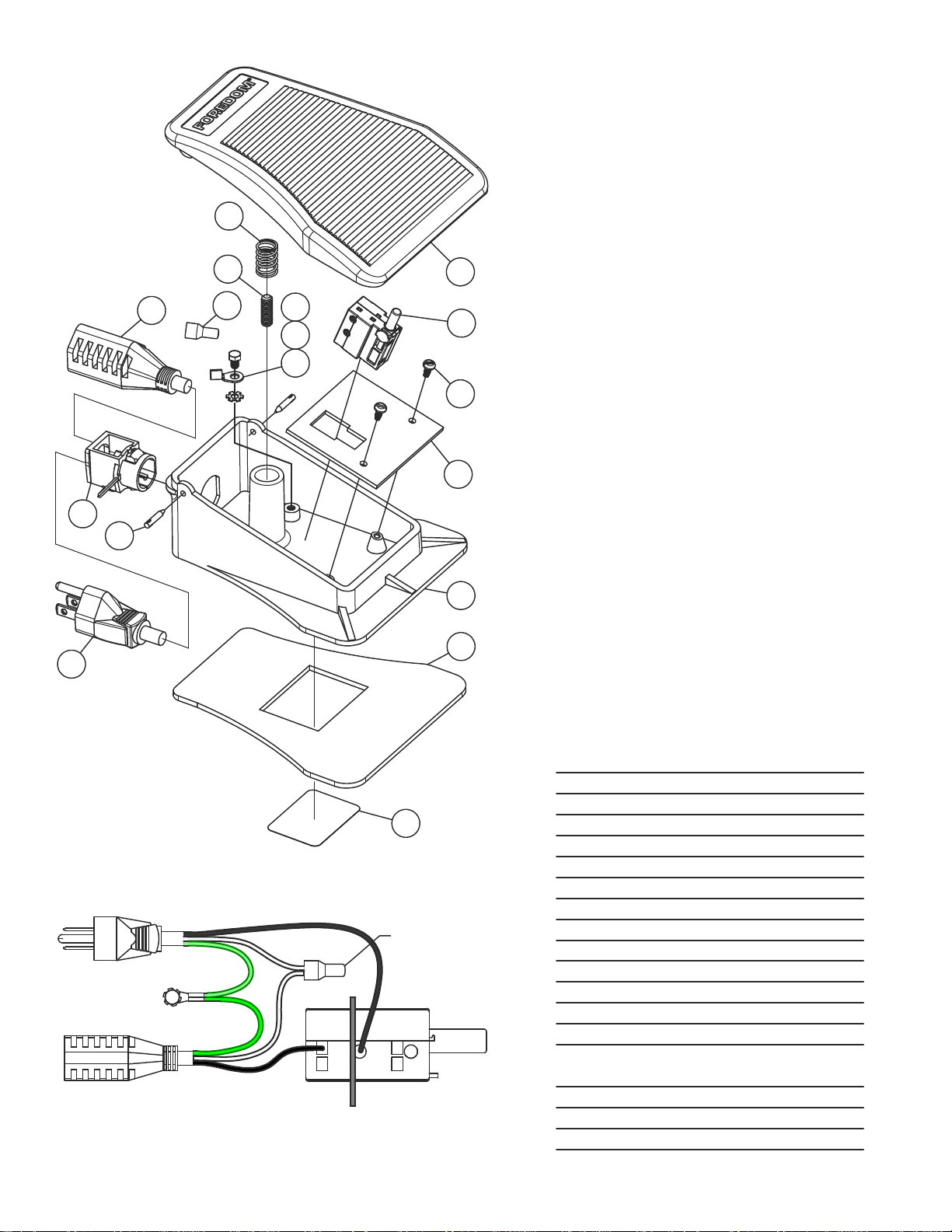
Foot Control, 115V
14
17
16
15
13
12
11
Instructions for Removing
and Replacing Trigger Switch
Disconnect Foot Control from Motor and Wall Outlet.
1.
With a punch and hammer drive two Pins (9) in until Cover (1)
lifts from each side of Base (5).
2.
Remove Cover and drive Pins outward with hammer and punch
to remove.
3.
Remove two Screws (3) from Bracket (4). After the wires have
been removed from the switch, as instructed in paragraph 4,
remove the switch from the board, insert the new sw itch in its
1
2
3
4
place, and follow the instructions in paragraph 5 and 6.
4.
On older Switches, all the terminals will be push -in, spring clamp
type. On newer Switches, Terminal 1 has a screw for fastening
the wire lead. To remove wires from the push-in terminals, insert
1.3mm [.05in] approximate diameter pin or th e bl ade of a jewel er's
screwdriver all the way into the terminal socket to release the spring
clamp. Grasp the tool and wire and pull them together out of the
socket. If you have difficulty removing the wires from the push-in
terminals and you have wire-cutting, stripping, and soldering tools,
you can cut the wires off where they exit from the terminals. To
prepare the cut wires for installation into the replacement Switch,
strip them back exactly 8.25 mm [5/16 in], then apply solder to the
stripped ends to fuse the strands together.
10
9
8
7
Wiring Diagram
Male Plug to
AC Power Source
1
Bracket
Wire
Connector
4
3
2
Attach Ground
Screw to Base
Female Receptacle
to Motor
}
GRN
GRN
WHT
BLK
BLK
WHT
6
5
FOREDOM The Foredom Electric Company
16 Stony Hill Rd., Bethel, CT 06801 • 203−792−8622
Fax: 203−796−7861
• www.foredom.net
5
6
Trigger Switch
5.
Insert new Trigger Switch into Bracket.
6.
Connect Wires to New Trigger Switch as shown in the
Wiring Diagram.
Push wires all the way in, so that no bare wire
is exposed. On Screw Terminal 1, push the wire lea d all the way
into the socket then tighten the screw firmly. Push the other
wire lead all the way into terminal 6. Pull on all the wires, making
sure they are secure.
7.
Install Bracket and Switch into Base using two Screws (3).
8.
Position wires around post of Base so wires will not
interfere with Cover travel.
9.
Install Cover over Spring (17) and align holes to Base.
Insert Pins (9) and seat them with hammer.
DescriptionPart No.Item
1
2
3
4
5
6
7
8
9
10
11
12
13
14
15
16
17
CP11030
CP10690
CP10542
CP10830
CoverCP10691
Trigger Switch, 125VCP10857
Screw, 6−32 x 5/16"CP10571
Bracket
Base
Base PadCP10753
Specification LabelSCT−1.LAB
Male CordsetCP10541
Hinge PinCP10584C
GrommetCP10578
Terminal RingCP10580
Lock Washer, #8CP10564
Screw, 8−32 x 1/4"CP10563
Female Cordset (SCT−1)
Female Cordset (SCH−1)
2 Wire ConnectorCP11029
Set ScrewCP10562
SpringCP10588
FORM DN 12/10
Qty
1
1
2
1
1
1
1
1
2
1
1
1
1
1
1
1
1
 Loading...