

FOREDOM 500, 500L, 500-2, 500L-2 Setup, Operation & Maintenance Manual
Replacement of Handpiece Pads: When install-
ing or replacing the Handpiece Pad Holder be
sure that the Adjustment Sleeve is tight. The
plunger shaft should extend at least 1/16″ beyond
the adjustment sleeve when the Plunger Shaft is
in its uppermost (withdrawn) position.
The rubber holder has a screw and locking nut for
attaching it to the plunger shaft. Screw the Pad
Holder into the plunger shaft and tighten the lock
nut with a 3/8″ wrench. Replacement pads can be
held in the holder with double faced pressure
sensitive tape.
Replacement of Motor Brushes: Be sure to
unplug motor before re plac ing motor brushes.
The motor brushes should be replaced when they
have worn down to 1/4″. To remove the brushes,
unscrew the brush caps on either side of motor.
Be sure to replace both motor brushes even if one
of them seems less worn than the other.
Replacement of Shafts and Sheaths: Shafts and
sheaths will last the longest when they are used as
straight as possible and when the shaft is cleaned
and lubricated regularly. There is no way to avoid
ultimate wear. A Massager may require several
replacement shafts and sheaths during its lifetime. Always keep a spare shaft on hand.
Repair Service:
Other service or repairs should
be done by a competent repair person or you can
return your Foredom equipment to the factory. If
you wish, send your Massager directly to the factory marked "Attention: Repair De part ment".
Enclose the item(s), a packing list, information
regarding the problem or repairs required, and your
contact information including daytime phone
number, email and mailing address. Estimates of
repair cost will be made upon request. If the cost
(labor plus parts) is more than fifty percent of the
price for a new replacement we will contact you and
recommend a trade-in offer.
For More Information
For more information on Foredom machines,
handpieces or ac ces so ries, contact your local
dealer. When no local dealer is available you
can also visit our website at www.foredom.net
for Foredom replacement parts.
Other contact information:
Email:
customerservice@blackstoneind.com
Foredom Electric Company
16 Stony Hill Road, Bethel, CT 06801
Phone: 203-792-8622
Fax: 203-796-7861
Form 1232 N-IH 9/17 Printed in USA
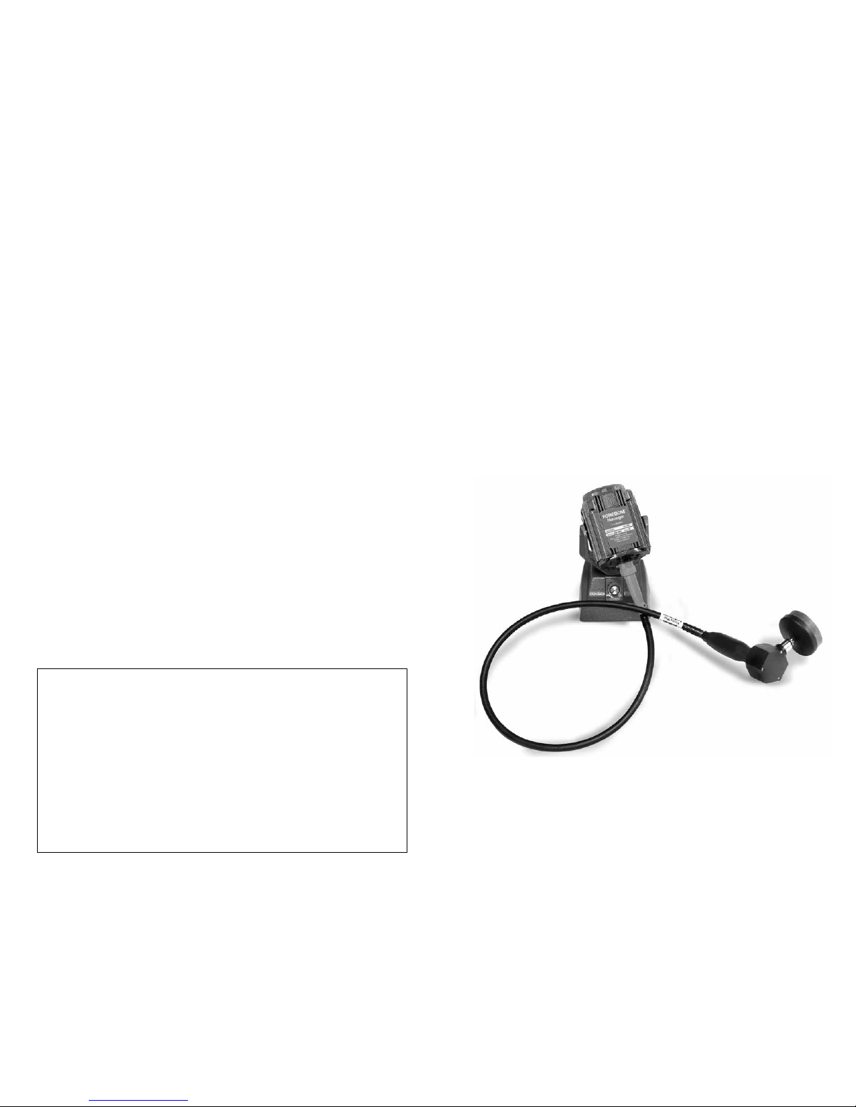
Massager
Models:
500
500L
500-2
500L-2
IMPORTANT!
Read Manual before operating this tool.
FOREDOM
®
www.foredom.net
Set-up, Assembly and
Maintenance Manual
Please retain your proof of purchase
for warranty repairs.
Recommended Spare Parts:
39″ Long Shaft S-93
36
1
⁄4″ Long Neoprene Sheath to use
with 39″ Long Shaft S-77N
Replacement Pad HP10254
Motor Brushes MP319P (Pair)
Foredom Flexible Shaft Grease MS10006
Optional Parts / Accessories:
66″ Long Shaft S-93-66
63
1
⁄4″ Long Sheath to use with
66″ Long Shaft S-77-66
Holder with Pad HP10255
Pad Holder HP10253
Pack of 6 Pads HP10254B
LIMITED WARRANTY
Warranty period is 2 years for motors, 90 days for handpieces, and 1 year for controls and switches.
Blackstone Industries, LLC d/b/a The Foredom Electric Company warrants, to the original purchaser only, that its
products will be free from defects in material or workmanship for the applicable period of time indicated above
following the purchase date. During the warranty period, the defective product will be repaired or replaced with
out charge or, at our sole option, the purchase price will be refunded. This warranty does not cover damage
caused in transit or by accident, misuse or ordinary wear.
ALL IMPLIED WARRANTIES INCLUDING, WITHOUT LIMITATION, IMPLIED WARRANTIES OF FITNESS FOR A
PARTICULAR PURPOSE AND MERCHANTABILITY, ARE LIMITED IN DURATION TO THE APPLICABLE
WARRANTY PERIOD. IN NO EVENT WILL WE BE LIABLE FOR ANY INCIDENTAL OR CONSEQUENTIAL
DAMAGES. Some states do not allow limitations on how long an implied warranty lasts or the exclusion or
limitation of incidental or consequential damages, so the above limitations or exclusion may not apply to you.
At our sole option, repair, replacement or refund will be made if the product is returned postage prepaid to:
Foredom Electric Company 16 Stony Hill Road Bethel, Connecticut 06801
All warranty repairs must be done at our factory at the above address. We will not pay any shipping or transpor
-
tation charges. Armatures, bearings, shafts, sheaths and duplex springs are not covered by this warranty.
This warranty gives you specific legal rights, and you may also have other rights which vary from state to state.
Operation
For the best performance, safety, and
maximum life, please follow these
general suggestions:
1. Try to avoid using the Massager with
sharp bends or loops in the flexible shaft.
This will reduce wear of the flexible shaft
and the sheath lining.
2. Never deliberately stall the motor or slow
it down near the stalling point by bearing
down too hard on the handpiece.
3. The Massager comes with a dial control
built into the base. Strokes can be varied
from 0 to 4,400 per minute with the turn
of the dial.
Maintenance and
Assembly
These simple maintenance procedures
should be done by the user:
1. Cleaning and lubrication of flexible shaft
and handpiece.
2. Replacement of motor brushes.
3. Replacement of worn shafts
and sheaths.
4. Replacement of handpiece pads.
Keep the Massager as free of dust and
dirt as possible. Never allow oil or
grease to accumulate on exposed
surfaces as this tends to collect dirt.
Lubrication
The motor has permanently lubricated bear ings and does not require lubrication.
The flexible shaft should be cleaned and
lubricated once every 100 hours of use.
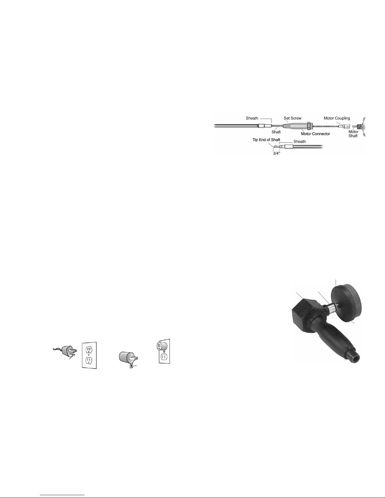
Expose the shaft by removing the handpiece
and then the sheath by loosening the set
screw in the motor connector (see Figure 1)
and sliding it off the shaft. Apply a light film
of Foredom flexible shaft grease (MS10006)
along the entire length of the shaft after wip ing off the old grease with a piece of cloth.
Replace the sheath by sliding it over the shaft
and tightening the set screw. Be sure to
follow the Adjustment Instructions below.
Shaft Replacement
1. Remove the motor connector. Left hand
thread, turn right. (See Figure 1)
2. Loosen the set screw on the old flexible shaft
motor coupling and slide the shaft coupling
off the motor shaft. (See Figure 1.) Tighten
the set screw of the new shaft onto the flat
on the motor shaft.
3. Put the motor connector back on the motor
by sliding it up the flexible shaft and tighten ing. Grease shaft as described above.
4. Now slide the sheath over the flexible shaft
with the plain sheath fitting (not the grooved
fitting) going toward the motor and into the
motor connection.
Adjustment of Shaft and Sheath
Before attaching handpiece, shaft and sheath
adjustment must be carefully checked. Place
the entire unit on a flat surface with shaft and
sheath extended straight. Adjust the exposed
tip of the flexible shaft so that it extends 3/4″
beyond the sheath, as shown above. This is
done by moving the sheath in or out of the
motor connector. When the correct ad just-
Front
Plate
Set Screw
Adjustment
Sleeve
Plunger Shaft
Handpiece
Pad Holder
Figure 1
Figure 2
Set Up
Check the voltage of your power before plugging in the motor. It should match the voltage
shown on the motor nameplate. Models 500
and 500L are for use on 115 Volt AC power.
Models 500-2 and 500L-2 are for use on 230
Volt AC power.
Note: The Massager Handpiece comes
attached to the motor. If you need to remove
the handpiece (when cleaning, for example),
loosen the set screw and just pull away from
the shaft and sheath with a strong motion. To
reattach, push the hand piece onto the shaft
tip and sheath fitting while motor is running
slowly. Be sure that the catch ball in the end
of the handpiece toward the sheath goes into
the groove in the sheath tip so that the handpiece will be held securely onto the sheath.
ment is made, tighten the screw in the motor
connector. The handpiece can now be reattached
as described in the Note: under “Set Up”.
H.60 Massager
Handpiece Maintenance
The handpiece should be cleaned and lubricated
once every 100 hours of use. Remove the Front
Plate to expose the ec cen tric cam and plunger
shaft. Flush out the old grease with a solvent and
regreasewith a tea spoon ful of Foredom grease,
being sure that all the moving parts are thoroughly lubricated. After regreasing, run the handpiece slowly for a few minutes to fully distribute
grease. The Ad just ment Sleeve retains a grease
seal and should be tightened to prevent leakage
of grease.
• Use proper grounding procedures. This tool
should be grounded while in use to protect
the operator from electric shock. The tool is
equipped with an approved 3-conductor cord
and a 3-prong grounding type plug to fit the
proper grounding receptacle. The green (or
green and yellow) conductor in the cord is the
grounding wire. Never connect the green (or
green and yellow) wire to a live terminal. If
your unit is for use on less than 150 volts, it
has a plug that looks like sketch A below. An
adapter (sketches B and C) can be used for
connecting plugs as shown in sketch A to
2-prong receptacles. The green colored rigid
ear, lug, etc., extending from the adapter must
be connected to a permanent ground such as
a properly grounded outlet box.
Some jurisdictions, including Canada,
prohibit the use of 3 to 2 prong adapters.
Where prohibited, they should not be used.
Use only 3-wire extension cords that have 3-
prong grounding type plugs and 3-pole type
plugs and 3-pole receptacles that accept the
tool’s plug. Always disconnect the power cord
before servicing the tool.
Replace a worn
cord immediately.
Models 500-2 and 500L-2 are equipped
with power plugs suitable for use in the
country for which they are intended.
 Loading...