

Foredom 1045 - Rotary User Manual
®
Safety Instructions
FOREDOM
Operation and
Maintenance Manual for
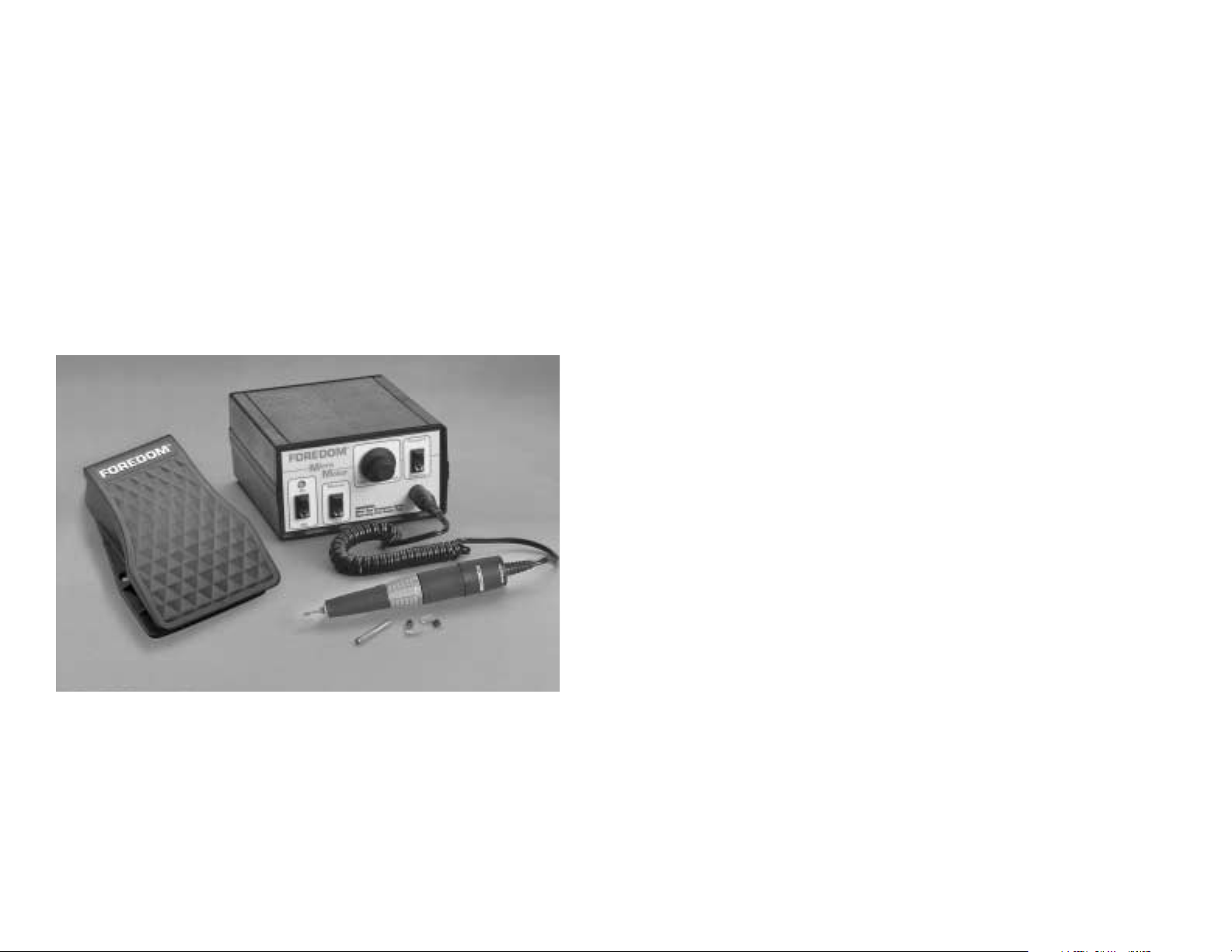
1045 Micro Motor Kit
FM3545
Control
• ALWAYS wear proper eye and face protection.
Safety glasses have been provided with your new Micro Motor. For your
own protection, they should be worn (or a face shield) whenever you
operate a Foredom®or any power tool to prevent serious eye or
face injuries.
• ONLY use accessories rated for 45,000 rpm or higher speeds when
operating this micro motor.
• ALWAYS find out the manufacturer's speed rating before using any
accessory.
• NEVER use or continue to use any accessory which appears to be
damaged, loose, vibrating or out of balance. Inspect each accessory for
cracks or flaws before using it.
• ALWAYS insert the shank or arbor of an accessory or mandrel into the
collet or chuck of the handpiece as far as possible in order to provide
proper support and close the collet or chuck securely.
• NEVER use excessive side pressures which may tend to bend or
break the shank or arbor of an accessory. Let the speed of the accessory
do the work.
FC-2000
Foot Pedal
3/32″ & 1/8″ Collets,
Spare Motor Brushes
For Your Safety:
• Read this Manual before operating your
Foredom Micro Motor Power Tool.
• Always wear eye protection while using
the Foredom Micro Motor Handpiece.
MH-145A
Handpiece
• DO NOT stall the motor by jamming or using excessive pressure on the
mounted point, buff, wheel or accessory. This can result in damage
to the motor.
• WEAR a dust protector to prevent you from inhaling harmful dust or debris
from grinding, carving or other operations performed with this power tool.
A Micro Motor Handpiece is a high speed rotary power tool which
can be dangerous and cause serious injury if it is not used properly.
NEVER operate it without wearing eye protection.
2

Assembly Instructions
Do not plug into power outlet before connecting handpiece or
foot pedal.
Front Panel (Figure 1)
Manual Dial
Speed Control
Power
On/Off
Indicator
Light
Power
On/Off
Switch
Control
Selector Switch
Rotation
Selection Switch
Handpiece
Connection Port
Rear Panel (Figure 2)
Keyway
Key
way
Foot Control
Connection Port
Fuse
Plug
Connecting Power Cord:
Before connecting power cord plug (see Figure 2) to a power outlet, put the
On/Off Selector Switch in the OFF position and turn the dial to the LOW
speed position. Be sure that the handpiece chuck is closed with (or
without) an accessory in it. (Operating the handpiece with the chuck in the
open position can severely damage the motor of the handpiece.) Now plug
in the power cord to a 115 Volt (or 230 Volt) AC current outlet. Refer to the
section below for selecting the Manual/Foot and Forward/Reverse switches.
Operating Instructions
FM3545 Control
Power On/Off Switch and Indicator Light:
With the Power On/Off Switch in the ON position and the Control Selector
Switch in the MANUAL position, the Power Indicator Light will go on
immediately and the handpiece will run at the speed set on the
Dial Speed Control.
Connecting Handpiece:
Attach the handpiece to the control by plugging the coiled cord into the
handpiece connection port on the lower right side of the front control panel
(see Figure 1). Be sure to align pins properly using keyway when plugging in
the cord.
NEVER turn or start the MH-145A Handpiece while chuck is in open
(unlocked) position. This can damage the handpiece. Always operate it
with a bur or other accessory in the chuck and with the chuck in the
closed position.
DO NOT operate the handpiece in the presence of any flammable liquid
or gas.
DO NOT cover the ventilation slots or handpiece motor with cloth or tape.
Air must pass freely through the intake and exhaust ventilation slots to properly cool the motor. If the power cord or plug to the handpiece is damaged,
repair or replace immediately. NEVER operate with a damaged power cord.
Connecting Foot Pedal:
The Foot Pedal Control can be used with either 115 Volt or 230 Volt models
of the control. Attach it by inserting the foot pedal connector pins into the
foot control connector port on rear panel of control (see Figure 2) using
keyway to properly align pins. Then tighten the threaded locking collar by
turning it clockwise. (It is not necessary to have the foot pedal connected to
the control box to operate the dial speed control.) The Micro Motor control
and handpiece are now ready to operate.
With the Power On/Off Switch in the ON position and the Control Selector
Switch in the FOOT position, the Power Indicator Light will go on but the
handpiece will not rotate until the Food Pedal is depressed.
Control Selector Switch:
With the Power On/Off Switch in the OFF position, select either foot or
manual speed control.
Forward/Reverse Rotation Selection Switch:
With Power On/Off Switch in OFF position, select the desired handpiece
direction by moving switch to FORWARD or REVERSE position. Do not
change handpiece direction while it is running. This can damage the
handpiece motor.
Manual Dial Speed Control:
The dial control will vary handpiece speed from low to full speed. It will only
function while Power On/Off Switch is in ON position and Control Selector
Switch is in MANUAL position.
Handpiece Overload Protection:
If the Handpiece is used with a locking ring left in the “R” position or in
overload condition, it will trigger the overload circuit protector. The Power
ON light will change in color from green to red and handpiece will stop.
Immediately turn off control by putting Power ON/OFF switch in OFF
position. Put power switch in ON position again when overload condition
is corrected.
3
4
 Loading...