

Page 1

Table of Contents
Introduction 4
Instrument Cluster 10
Warning and control lights 10
Gauges 14
Entertainment Systems 16
AM/FM stereo cassette with CD 16
AM/FM stereo cassette 18
AM/FM stereo with CD 25
Rear seat controls 28
Climate Controls 31
Manual heating and air conditioning 31
Rear window defroster 35
Lights 36
Headlamps 36
Turn signal control 39
Bulb replacement 41
Driver Controls 45
Windshield wiper/washer control 45
Steering wheel adjustment 46
Power windows 53
Mirrors 54
Speed control 56
Message center 63
Locks and Security 77
Keys 77
Locks 77
Anti-theft system 79
1
Page 2

Table of Contents
Seating and Safety Restraints 89
Seating 89
Safety restraints 99
Air bags 112
Child restraints 118
Driving 132
Starting 132
Brakes 135
Traction control 137
Transmission operation 140
Trailer towing 147
Roadside Emergencies 152
Getting roadside assistance 152
Hazard flasher switch 153
Fuel pump shut-off switch 153
Fuses and relays 154
Changing tires 163
Jump starting 169
Wrecker towing 174
Customer Assistance 175
Reporting safety defects (U.S. only) 183
Cleaning 184
2
Page 3

Table of Contents
Maintenance and Specifications 190
Engine compartment 192
Engine oil 193
Battery 196
Fuel information 203
Low tire warning system 218
Part numbers 223
Refill capacities 224
Lubricant specifications 225
Accessories 230
Index 233
All rights reserved. Reproduction by any means, electronic or mechanical
including photocopying, recording or by any information storage and retrieval
system or translation in whole or part is not permitted without written
authorization from Ford Motor Company. Ford may change the contents without
notice and without incurring obligation.
Copyright © 2002 Ford Motor Company
3
Page 4

Introduction
CALIFORNIA Proposition 65 Warning
WARNING: Engine exhaust, some of its constituents, and
certain vehicle components contain or emit chemicals known to
the State of California to cause cancer and birth defects or other
reproductive harm. In addition, certain fluids contained in vehicles and
certain products of component wear contain or emit chemicals known
to the State of California to cause cancer and birth defects or other
reproductive harm.
CONGRATULATIONS
Congratulations on acquiring your new Ford. Please take the time to get
well acquainted with your vehicle by reading this handbook. The more
you know and understand about your vehicle the greater the safety and
pleasure you will derive from driving it.
For more information on Ford Motor Company and its products visit the
following website:
• In the United States: www.ford.com
• In Canada: www.ford.ca
• In Australia: www.ford.com.au
• In Mexico: www.ford.com.mx
Additional owner information is given in separate publications.
This Owner’s Guide describes every option and model variant available
and therefore some of the items covered may not apply to your
particular vehicle. Furthermore, due to printing cycles it may describe
options before they are generally available.
Remember to pass on the Owner’s Guide when reselling the vehicle. It is
an integral part of the vehicle.
Fuel pump shut-off switch In the event of an accident the
safety switch will automatically cut off the fuel supply to the
engine. The switch can also be activated through sudden vibration
(e.g. collision when parking). To reset the switch, refer to the Fuel
pump shut-off switch in the Roadside emergencies chapter.
4
Page 5
Introduction
SAFETY AND ENVIRONMENT PROTECTION
Warning symbols in this guide
How can you reduce the risk of personal injury and prevent possible
damage to others, your vehicle and its equipment? In this guide, answers
to such questions are contained in comments highlighted by the warning
triangle symbol. These comments should be read and observed.
Warning symbols on your vehicle
When you see this symbol, it is
imperative that you consult the
relevant section of this guide before
touching or attempting adjustment
of any kind.
Protecting the environment
We must all play our part in
protecting the environment. Correct
vehicle usage and the authorized
disposal of waste cleaning and
lubrication materials are significant
steps towards this aim. Information in this respect is highlighted in this
guide with the tree symbol.
BREAKING-IN YOUR VEHICLE
Your vehicle does not need an extensive break-in. Try not to drive
continuously at the same speed for the first 1,600 km (1,000 miles) of
new vehicle operation. Vary your speed to allow parts to adjust
themselves to other parts.
Drive your new vehicle at least 800 km (500 miles) before towing a
trailer.
Do not add friction modifier compounds or special break-in oils during
the first few thousand kilometers (miles) of operation, since these
additives may prevent piston ring seating. See Engine oil in the
Maintenance and specifications chapter for more information on oil
usage.
5
Page 6

Introduction
SPECIAL NOTICES
Emission warranty
The New Vehicle Limited Warranty includes Bumper-to-Bumper
Coverage, Safety Restraint Coverage, Corrosion Coverage, and 7.3L
Power Stroke Diesel Engine Coverage. In addition, your vehicle is eligible
for Emissions Defect and Emissions Performance Warranties. For a
detailed description of what is covered and what is not covered, refer to
the Warranty Guide that is provided to you along with your Owner’s
Guide.
Data Recording
Computers in your vehicle are capable of recording detailed data
potentially including but not limited to information such as:
• the use of restraint systems including seat belts by the driver and
passengers,
• information about the performance of various systems and modules in
the vehicle, and
• information related to engine, throttle, steering, brake or other system
status.
Any of this information could potentially including information regarding
how the driver operates the vehicle potentially including but not limited
to information regarding vehicle speed, brake or accelerator application
or steering input. This information may be stored during regular
operation or in a crash or near crash event.
This stored information may be read out and used by:
• Ford Motor Company.
• service and repair facilities.
• law enforcement or government agencies.
• others who may assert a right or obtain your consent to know such
information.
6
Page 7

Introduction
Special instructions
For your added safety, your vehicle is fitted with sophisticated electronic
controls.
Please read the section Supplemental Restraint System (SRS)
in the Seating and safety restraints chapter. Failure to follow
the specific warnings and instructions could result in personal injury.
Front seat mounted rear facing child or infant seats should
NEVER be used in front of a passenger side air bag unless the
air bag can be and is turned OFF.
MIDDLE EAST/NORTH AFRICA VEHICLE SPECIFIC INFORMATION
For your particular global region, your vehicle may be equipped with
features and options that are different from the ones that are described
in this Owner Guide; therefore, a supplement has been supplied that
complements this book. By referring to the pages in the provided
supplement, you can properly identify those features, recommendations
and specifications that are unique to your vehicle. Refer to this Owner
Guide for all other required information and warnings.
7
Page 8
Introduction
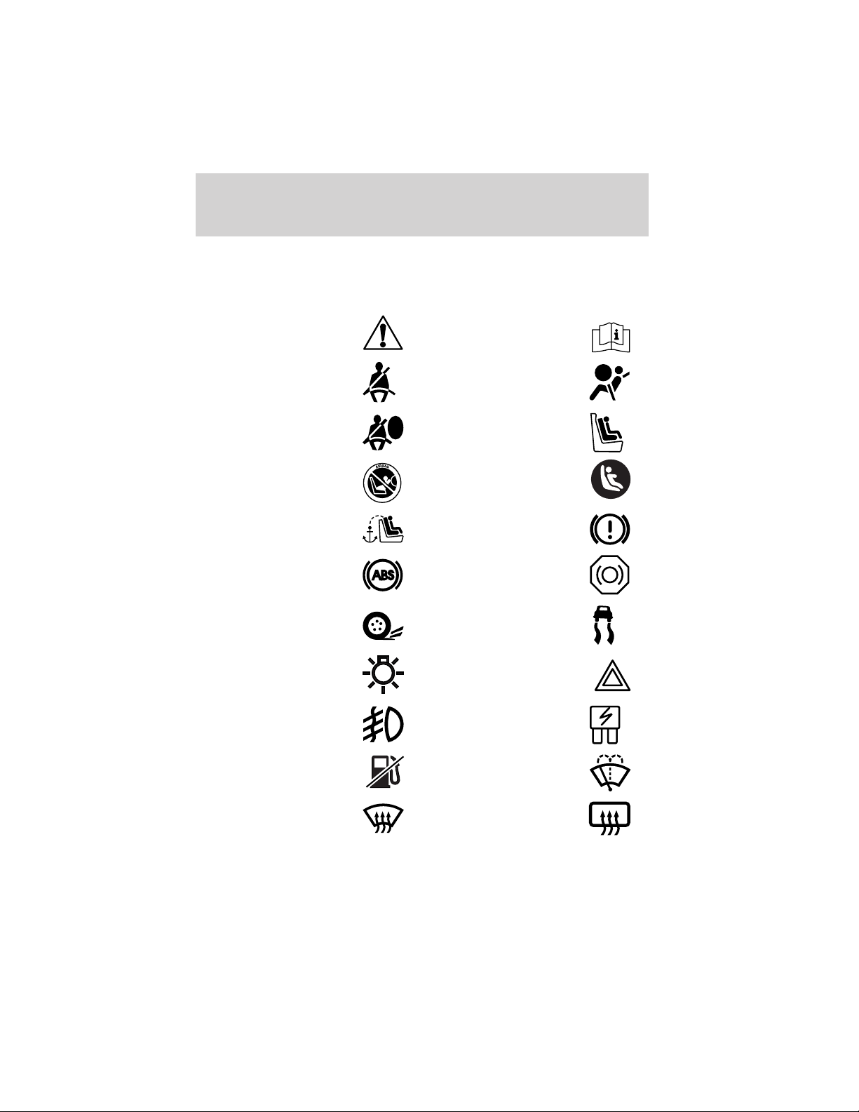
These are some of the symbols you may see on your vehicle.
Vehicle Symbol Glossary
Safety Alert
Fasten Safety Belt Air Bag-Front
Air Bag-Side Child Seat
Child Seat Installation
Warning
Child Seat Tether
Anchor
Anti-Lock Brake System
Traction Control AdvanceTrac
Master Lighting Switch Hazard Warning Flasher
Fog Lamps-Front Fuse Compartment
See Owner’s Guide
Child Seat Lower
Anchor
Brake System
Brake Fluid Non-Petroleum Based
Fuel Pump Reset Windshield Wash/Wipe
Windshield
Defrost/Demist
8
Rear Window
Defrost/Demist
Page 9
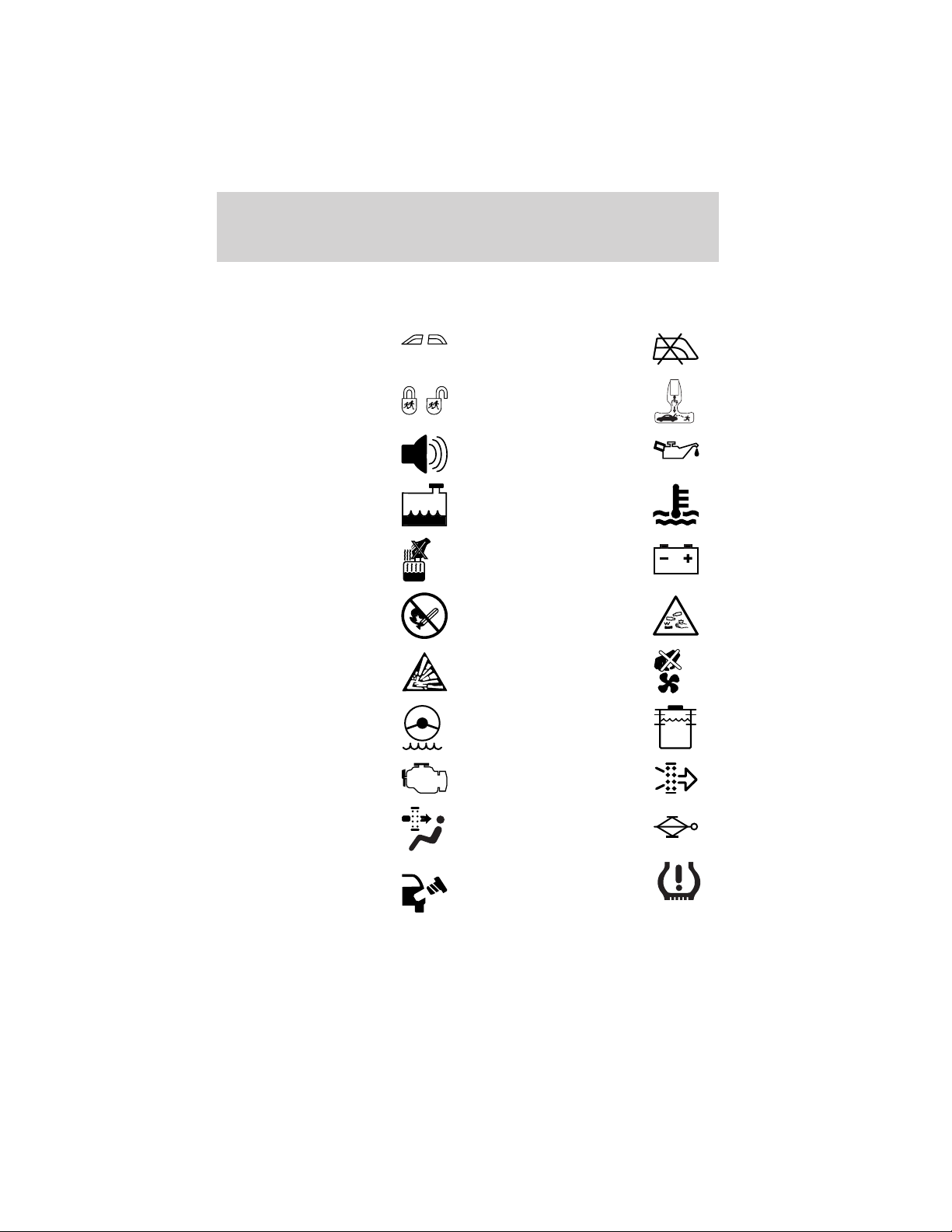
Vehicle Symbol Glossary
Introduction
Power Windows
Front/Rear
Child Safety Door
Lock/Unlock
Power Window Lockout
Interior Luggage
Compartment Release
Symbol
Panic Alarm Engine Oil
Engine Coolant
Engine Coolant
Temperature
Do Not Open When Hot Battery
Avoid Smoking, Flames,
or Sparks
Battery Acid
Explosive Gas Fan Warning
Power Steering Fluid
Maintain Correct Fluid
Level
Emission System Engine Air Filter
MAX
MIN
Passenger Compartment
Air Filter
Jack
Check fuel cap Low tire warning
9
Page 10
Instrument Cluster
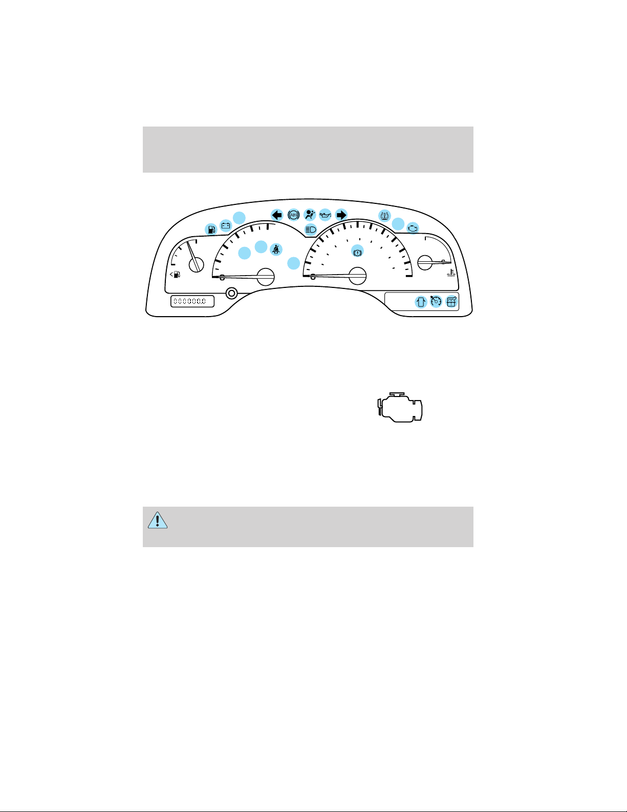
WARNING LIGHTS AND CHIMES
CHECK
FUEL
CAP
MPH
40
40
60
80
BRAKE
5
4
TRAC
ACTIVE
RPMX1000
6
7
20
THEFT
FUEL
F
E
mi
3
TRAC
2
OFF
1
Warning lights and gauges can alert you to a vehicle condition that may
become serious enough to cause expensive repairs. A warning light may
illuminate when a problem exists with one of your vehicle’s functions.
Many lights will illuminate when you start your vehicle to make sure the
bulb works. If any light remains on after starting the vehicle, have the
respective system inspected immediately.
Check engine: The Check Engine
indicator light illuminates when the
ignition is first turned to the ON
position to check the bulb. Solid
illumination after the engine is started indicates the On Board
Diagnostics System (OBD-II) has detected a malfunction. Refer to On
board diagnostics (OBD-II) in the Maintenance and Specifications
chapter. If the light is blinking, engine misfire is occurring which could
damage your catalytic converter. Drive in a moderate fashion (avoid
heavy acceleration and deceleration) and have your vehicle serviced
immediately.
O/D
OFF
80
TEMP
120
100
160
km/h
120
200
H
Under engine misfire conditions, excessive exhaust temperatures
could damage the catalytic converter, the fuel system, interior
floor coverings or other vehicle components, possibly causing a fire.
Check fuel cap: Illuminates when
the fuel cap may not be properly
installed. Continued driving with
this light on may cause the Check
CHECK
FUEL
CAP
engine warning light to come on,
refer to Fuel filler cap in the Maintenance and Specification chapter.
10
Page 11
Instrument Cluster
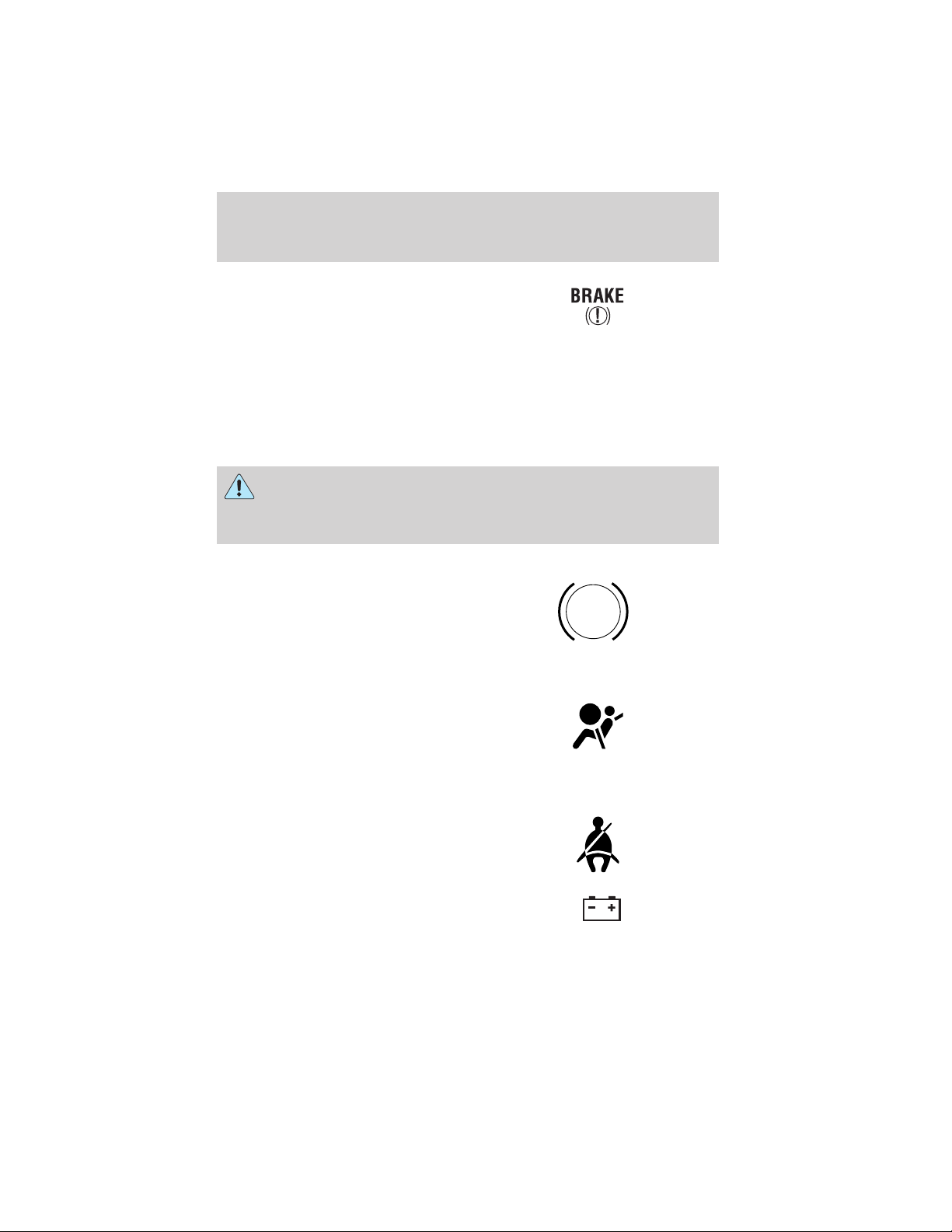
Brake system warning light: To
confirm the brake system warning
light is functional, it will
momentarily illuminate when the
ignition is turned to the ON position when the engine is not running, or
in a position between ON and START, or by applying the parking brake
when the ignition is turned to the ON position. If the brake system
warning light does not illuminate at this time, seek service immediately
from your dealership. Illumination after releasing the parking brake
indicates low brake fluid level and the brake system should be inspected
immediately by your servicing dealership.
Driving a vehicle with the brake system warning light on is
dangerous. A significant decrease in braking performance may
occur. It will take you longer to stop the vehicle. Have the vehicle
checked by your dealer immediately.
Anti-lock brake system: If the
ABS light stays illuminated or
continues to flash, a malfunction has
been detected, have the system
serviced immediately. Normal
braking is still functional unless the brake warning light also is
illuminated.
Air bag readiness: If this light fails
to illuminate when ignition is turned
to ON, continues to flash or remains
on, have the system serviced
immediately. A chime will also sound when a malfunction in the
supplemental restraint system has been detected.
Safety belt: Reminds you to fasten
your safety belt. A chime will also
sound to remind you to fasten your
safety belt.
ABS
Charging system: Illuminates when
the battery is not charging properly.
11
Page 12
Instrument Cluster
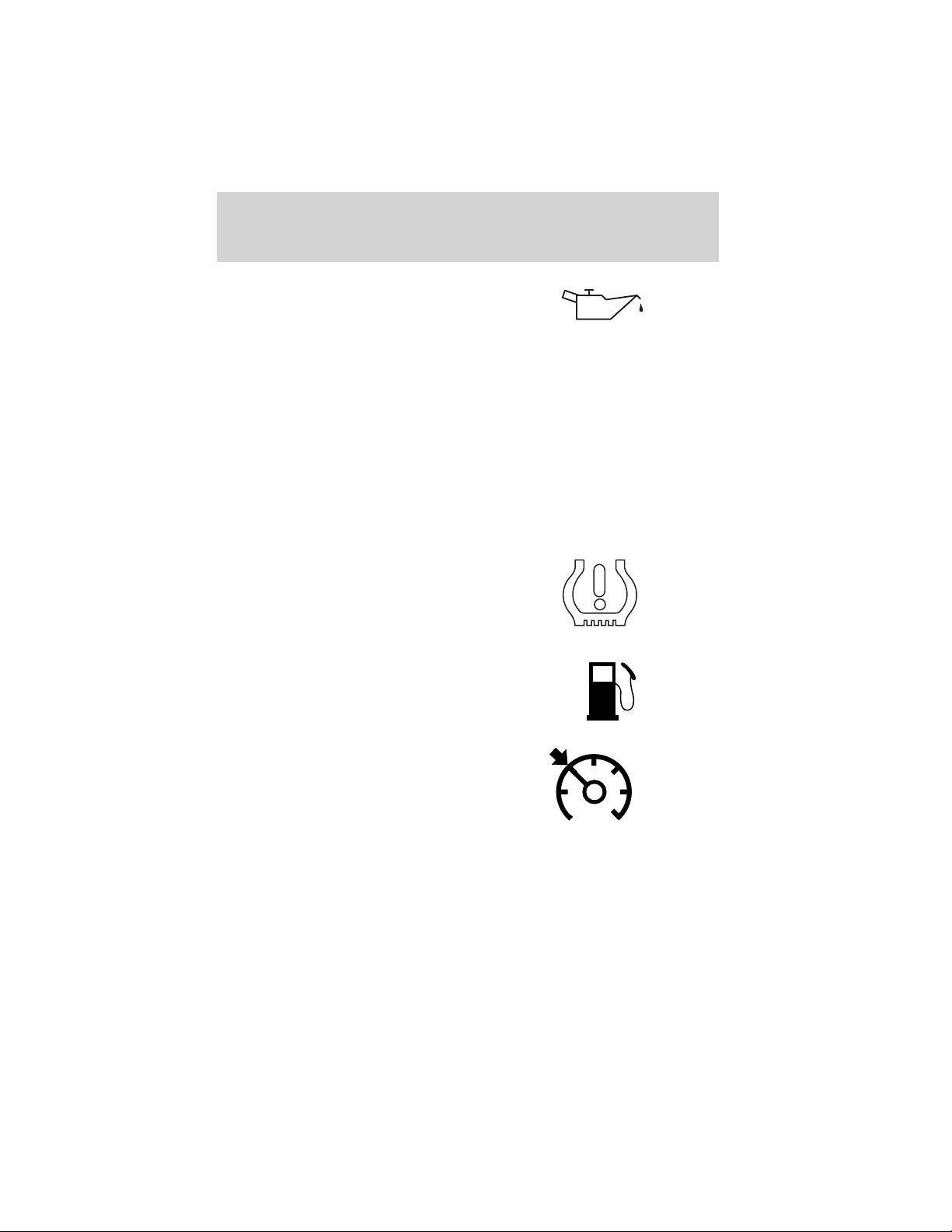
Engine oil pressure: Illuminates
when the oil pressure falls below the
normal range, refer to Engine oil in
the Maintenance and
specifications chapter.
Traction Control娂 or
AdvanceTrac娂 active
(if equipped): Illuminates when
the Traction Control娂 is active,
refer to the Driving chapter for more information.
Traction Control娂 or
AdvanceTrac娂 off light
(if equipped): Illuminates when
the Traction Control娂 has been
disabled (by the driver or as a result of a system failure). Refer to the
Driving chapter for more information.
Low tire warning: Illuminates
when the low tire warning system is
enabled. If the light remains on
while driving, the tire pressure
should be checked, refer to Low
tire warning in the Maintenance and Specifications chapter.
Low fuel: Illuminates when the fuel
level in the fuel tank is at or near
empty (refer to Fuel gauge in this
chapter).
TRAC
ACTIVE
TRAC
OFF
Speed control: Illuminates when
the speed control is engaged. Turns
off when the speed control system
is disengaged.
O/D off: Illuminates when the
overdrive function of the
transmission has been turned off.
12
O/D
OFF
Page 13
Instrument Cluster
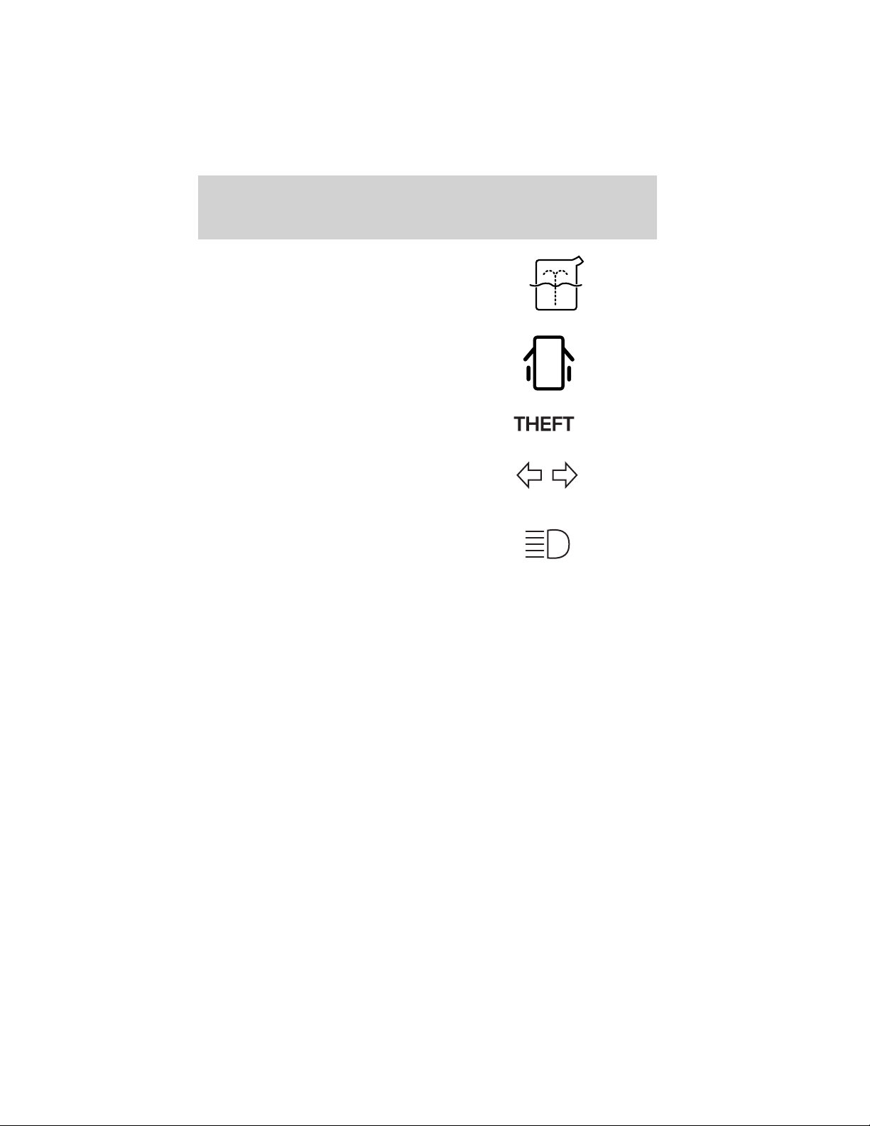
Low washer fluid: Illuminates
when the windshield washer fluid is
low.
Door ajar: Illuminates when the
ignition is in the ON position and
any door is open.
Anti-theft system: Flashes when
the Securilock娂 Passive Anti-theft
System has been activated.
Turn signal: Illuminates when the
left or right turn signal or the
hazard lights are turned on. If the
indicators stay on or flash faster, check for a burned out bulb.
High beams: Illuminates when the
high beam headlamps are turned on.
Key-in-ignition warning chime: Sounds when the key is left in the
ignition in the OFF/LOCK or ACC position and the driver’s door is
opened.
Headlamps on warning chime: Sounds when the headlamps or parking
lamps are on, the ignition is off (and the key is not in the ignition) and
the driver’s door is opened.
Turn signal warning chime: Sounds when the turn signal lever has
been activated to signal a turn and not turned off after the vehicle is
driven more than 0.8 km (1/2 mile).
13
Page 14
Instrument Cluster
GAUGES
CHECK
FUEL
CAP
5
4
TRAC
ACTIVE
RPMX1000
6
7
THEFT
FUEL
F
E
mi
3
TRAC
2
OFF
1
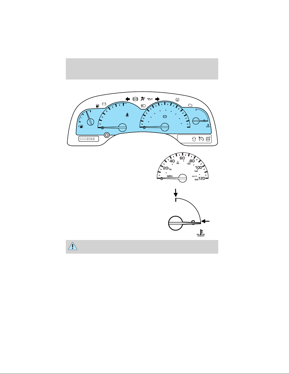
Speedometer: Indicates the
current vehicle speed.
Engine coolant temperature
gauge: Indicates engine coolant
temperature. At normal operating
temperature, the needle will be in
the normal range (between “H” and
“C”). If it enters the red section,
the engine is overheating. Stop
the vehicle as soon as safely
possible, switch off the engine
and let the engine cool.
20
MPH
40
80
40
TEMP
60
BRAKE
O/D
OFF
80
TEMP
120
100
160
km/h
120
200
H
H
14
Never remove the coolant reservoir cap while the engine is
running or hot.
Page 15
Instrument Cluster
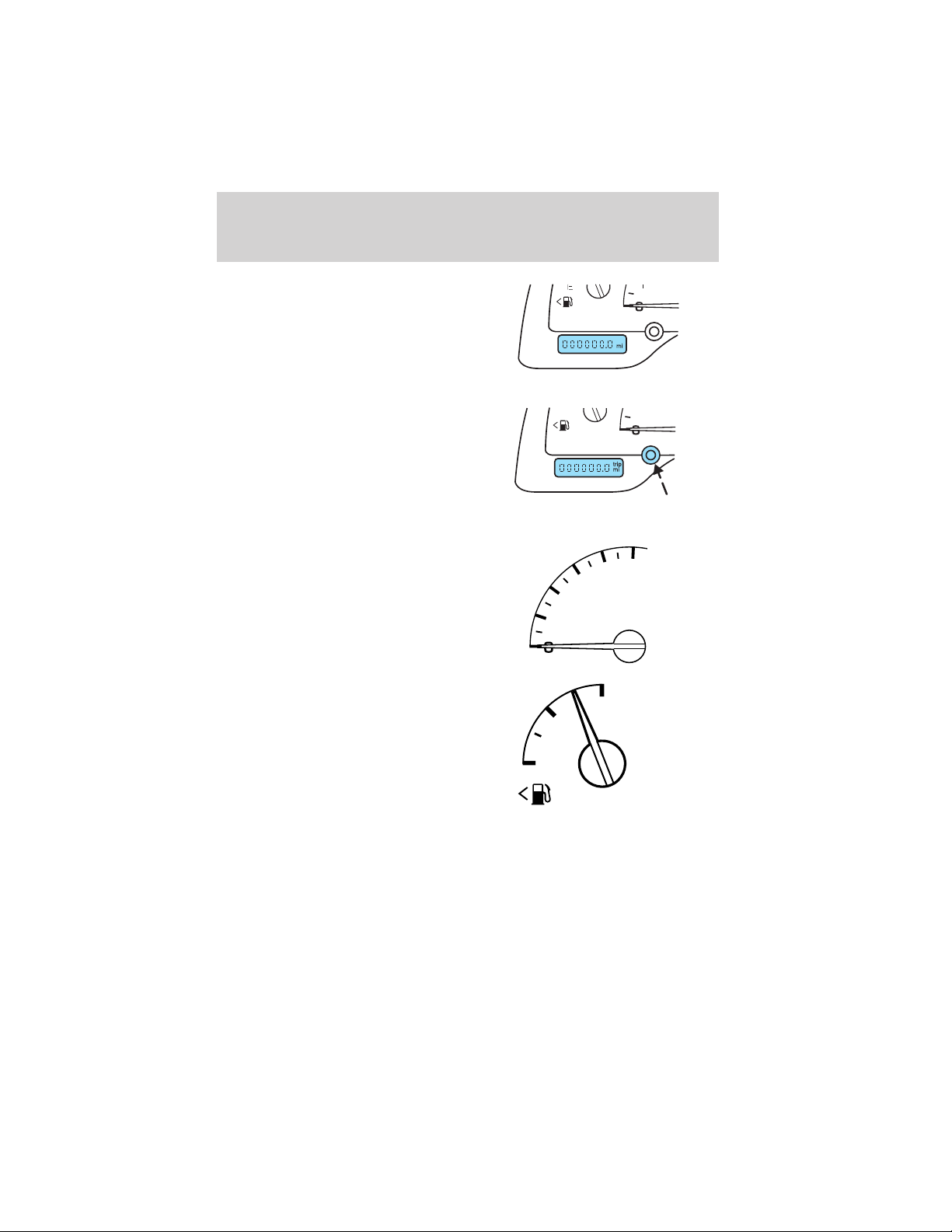
Odometer: Registers the total
kilometers (miles) of the vehicle.
Trip odometer: Registers the
kilometers (miles) of individual
journeys. To reset, depress the
control.
Low tire warning reset: May be
used to reset the Low Tire Warning
System, refer to Low Tire Warning in the Maintenance and
Specifications chapter.
Tachometer: Indicates the engine
speed in revolutions per minute.
Driving with your tachometer
pointer continuously at the top of
the scale may damage the engine.
2
1
3
5
4
RPMX1000
6
7
Fuel gauge: Indicates
approximately how much fuel is left
in the fuel tank (when the ignition
is in the ON position). The fuel
gauge may vary slightly when the
vehicle is in motion or on a grade.
The arrow near the fuel pump icon
indicates which side of the vehicle
the fuel filler door is located.
Refer to Filling the tank in the Maintenance and Specifications
chapter for more information..
E
F
FUEL
15
Page 16
Entertainment Systems
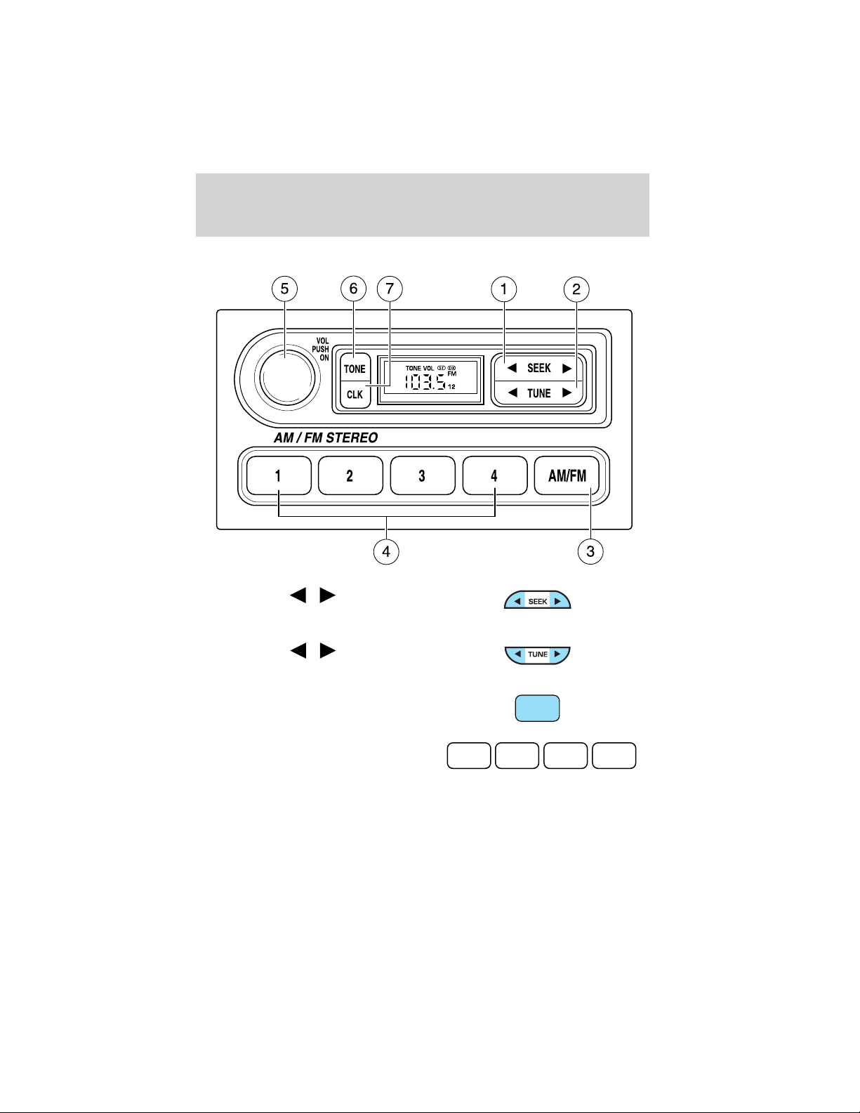
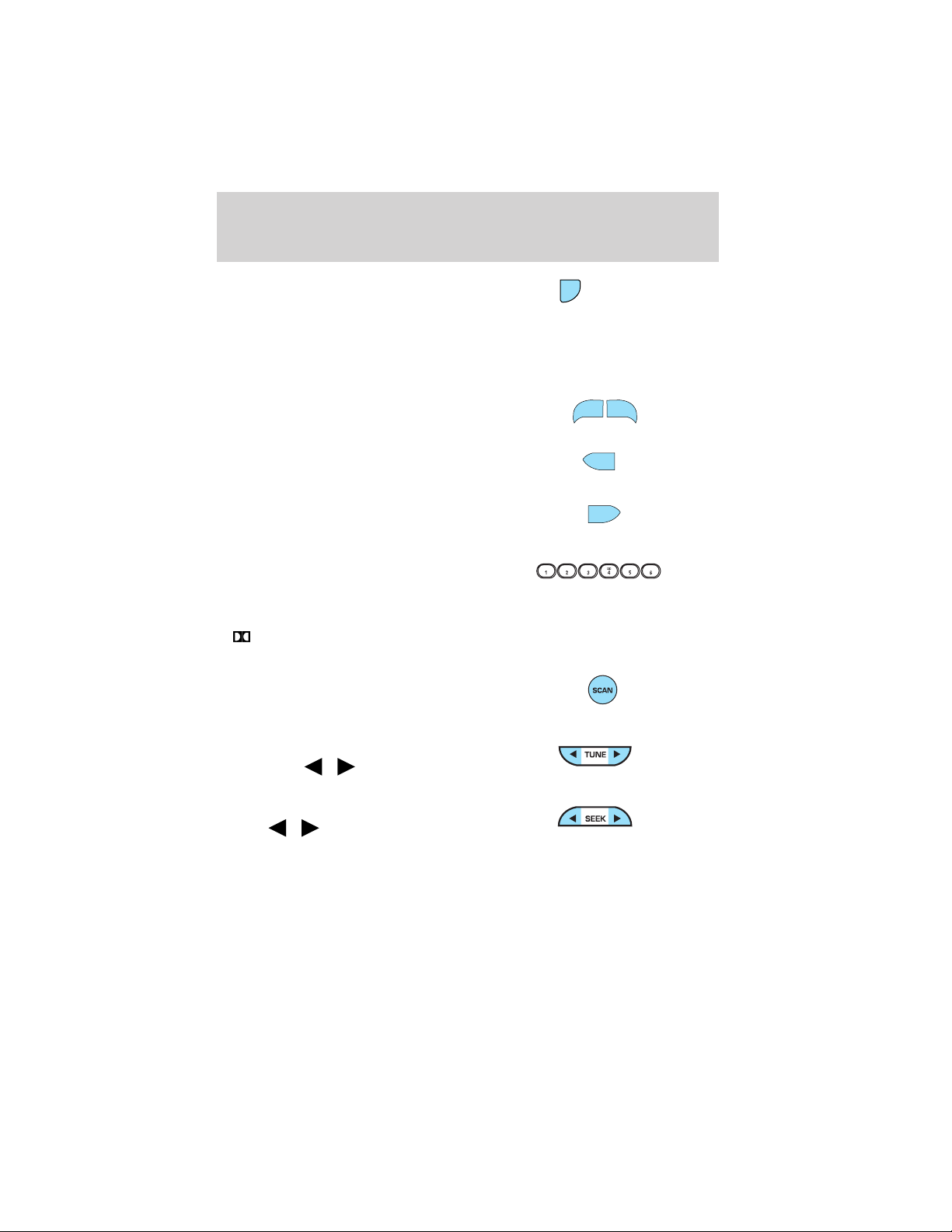
AM/FM STEREO
1. Seek: Press
/ to find the
next listenable station down/up the
frequency band.
2. Tune: Press
/ to manually
adjust the radio frequency down/up.
3. AM/FM: Press to choose a
frequency band in radio mode.
4. Memory preset buttons: To set
a station: Select frequency band
1 2 3 4
AM/FM1/FM2; tune to a station,
press and hold a preset button until sound returns.
16
AM/FM
Page 17
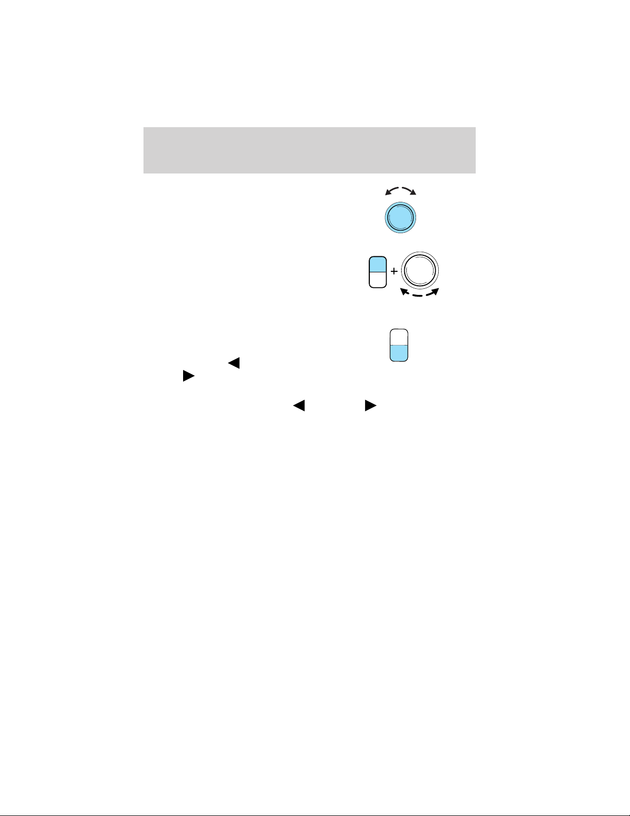
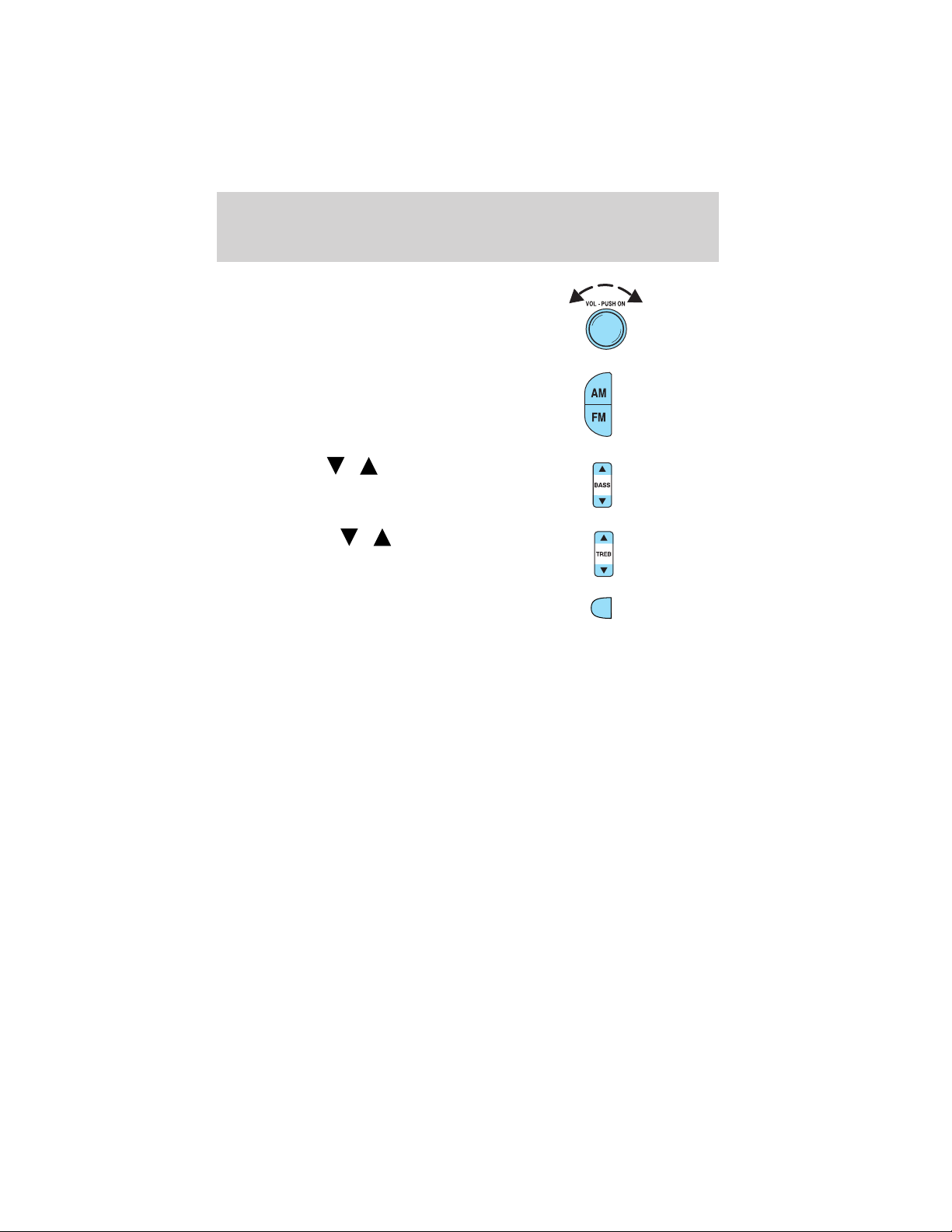
Entertainment Systems
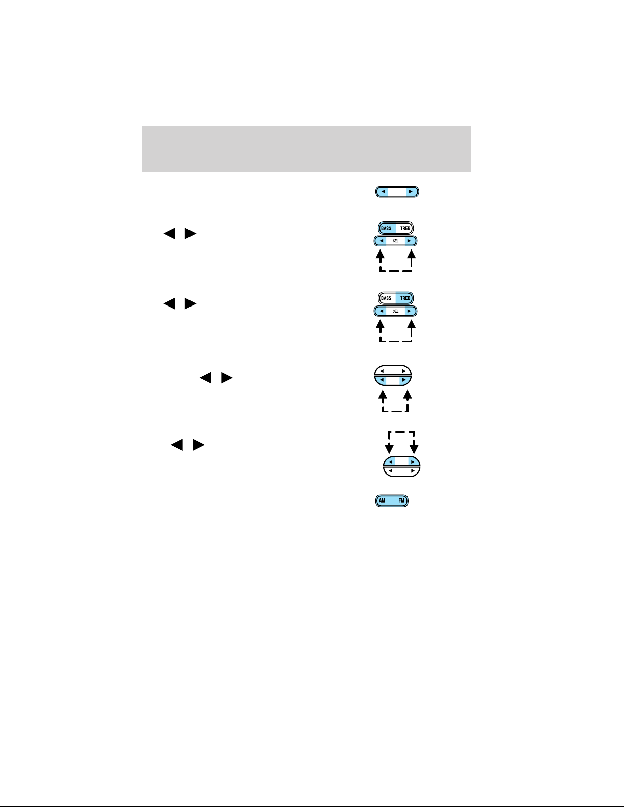
5. Power/volume: Press to turn
ON/OFF; turn to increase or
decrease volume levels.
6. Tone: Press TONE until the
desired level — Bass, Treble, Fade
appears on the display. Turn the
volume control to raise/lower the
TONE
CLK
VOL
PUSH
ON
VOL
PUSH
ON
levels, or to move the audio sound
from the right to left or the front to
back (if equipped).
7. CLK (Clock): To set the hour,
press and hold CLK until CLOCK
SET appears in the display. Press
SEEK to decrease
increase
the hours.
or
T
O
N
E
C
L
K
To set the minute, press and hold CLK until CLOCK SET appears in the
display. Press TUNE to decrease
or increase the minutes.
17
Page 18
Entertainment Systems
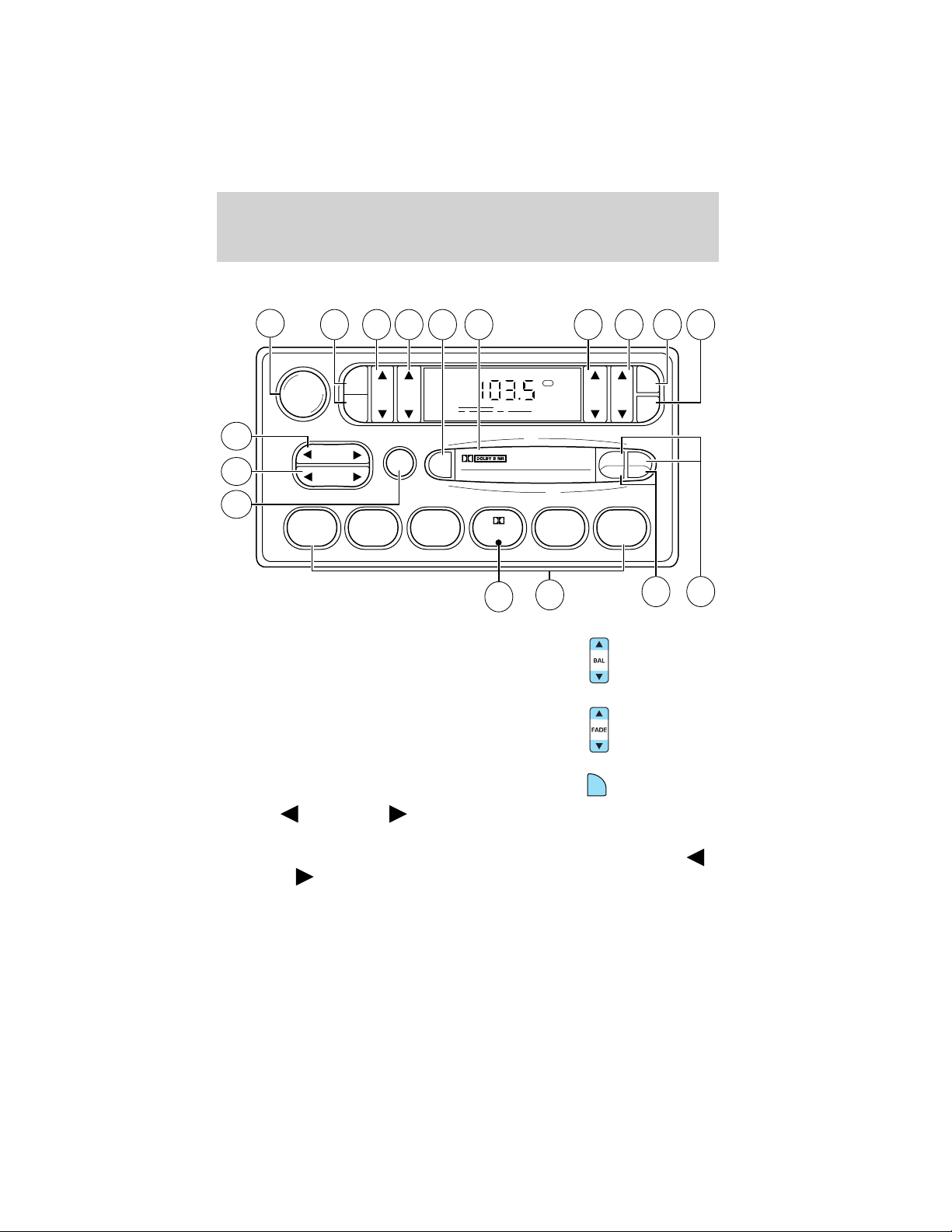
AM/FM STEREO CASSETTE
12
VOL - PUSH ON
13 14 15 16 17 1 234
AM
BASS TREB BAL FADE
FM
11
10
SEEK
TUNE
SCAN
EJ
9
123456
1. Balance: Press to shift sound to
the left/right speakers.
2. Fade: Press to shift sound to the
rear/front speakers.
FM1
ST
8
7
SIDE
REW FF
CLK
TAPE
AMS
1 - 2
65
3. CLK: To set the hour, press and
hold CLK. Then press SEEK to
decrease
or increase the
CLK
hours.
To set the minute, press and hold CLK and press TUNE to decrease
or increase the minutes.
18
Page 19
Entertainment Systems
4. Tape AMS: In tape mode, press
and hold to activate Automatic
TAPE
AMS
Music Search (allows you to quickly
locate the beginning of the tape selection being played or to skip to the
next selection). Then, press REW (for the beginning of the current
selection) or FF (to advance to the next selection). The tape MUST have
a blank section of at least four seconds duration between programs.
5. Side 1–2: Press to change tape
SIDE 1 - 2
direction.
6. REW (rewind): Press to rewind
REW
the tape.
FF (fast forward): Press to
FF
advance the tape.
7. Memory preset buttons: To set
a station: Select frequency band
AM/FM1/FM2; tune to a station,
press and hold a preset button until sound returns.
Dolby威 noise reduction: Works in tape mode only. Reduces tape
8.
noise and hiss; press to activate/deactivate.
9. Scan: Press SCAN to hear a brief
sampling of all listenable radio
stations or all tape selections. Press
again to stop.
10. Tune: Works in radio mode only.
Press TUNE
/ to change
frequency down/up
11. Seek: Press and
release
/ for previous/next
strong station, selection or track.
19
Page 20
Entertainment Systems
12. Power/volume: Press to turn
ON/OFF; turn to increase or
decrease volume levels.
13. AM/FM: Press to choose a
frequency band in radio mode.
14. Bass: Press
/ to
decrease/increase the bass output.
15. Treble: Press
/ to
decrease/increase the treble output.
16. EJ (Eject): Press to eject a
EJ
tape.
17. Cassette door: Insert a cassette into the cassette door.
20
Page 21

Entertainment Systems
PREMIUM AM/FM STEREO/CASSETTE/SINGLE CD
1. Power/volume: Press to turn
ON/OFF; turn to increase/decrease
volume.
2. Scan: Press to hear a brief
sampling of all listenable stations,
tape selections or CD tracks. Press
again to stop.
3. CD Door: Insert a CD with the
label side up.
SCAN
21
Page 22
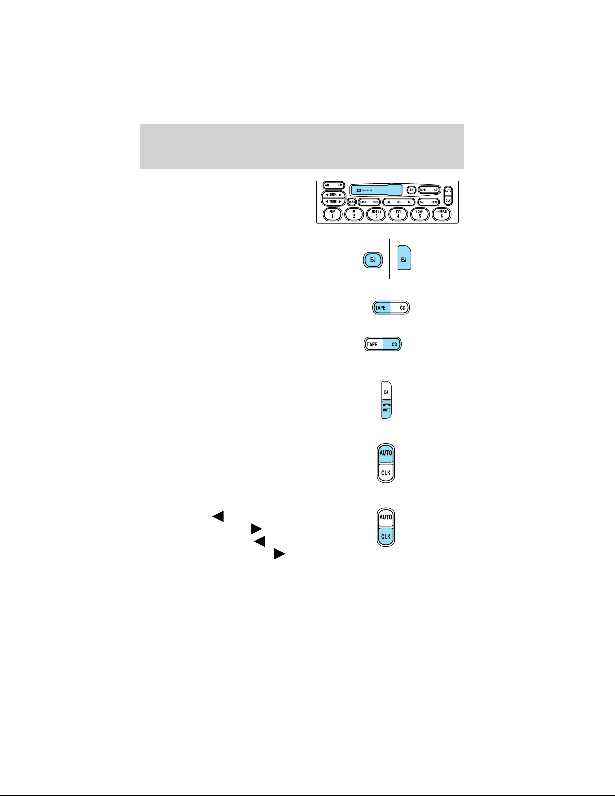
Entertainment Systems
4. Cassette door: Insert the
cassette with the opening to the
right.
5. Eject: Press to eject the
cassette/CD. The radio will resume
playing.
6. Tape: Press to start tape play.
Press to stop tape during
rewind/fast forward.
CD: Press to start CD play. With the
dual media audio, press CD to
toggle between single CD and CD
changer play (if equipped).
7. Mute: Press to MUTE playing
media; press again return to playing
media.
8. Auto: Press to set first six
strongest stations (if available) into
AM, FM1 or FM2 memory buttons;
press again to return to normal
stations.
9. Clock: Press and hold to set the
clock. Press the
decrease hours or SEEK to
increase hours. Press the
to decrease minutes or TUNE to
increase minutes. If your vehicle has a stand alone clock this control will
not function.
22
SEEK to
TUNE
Page 23
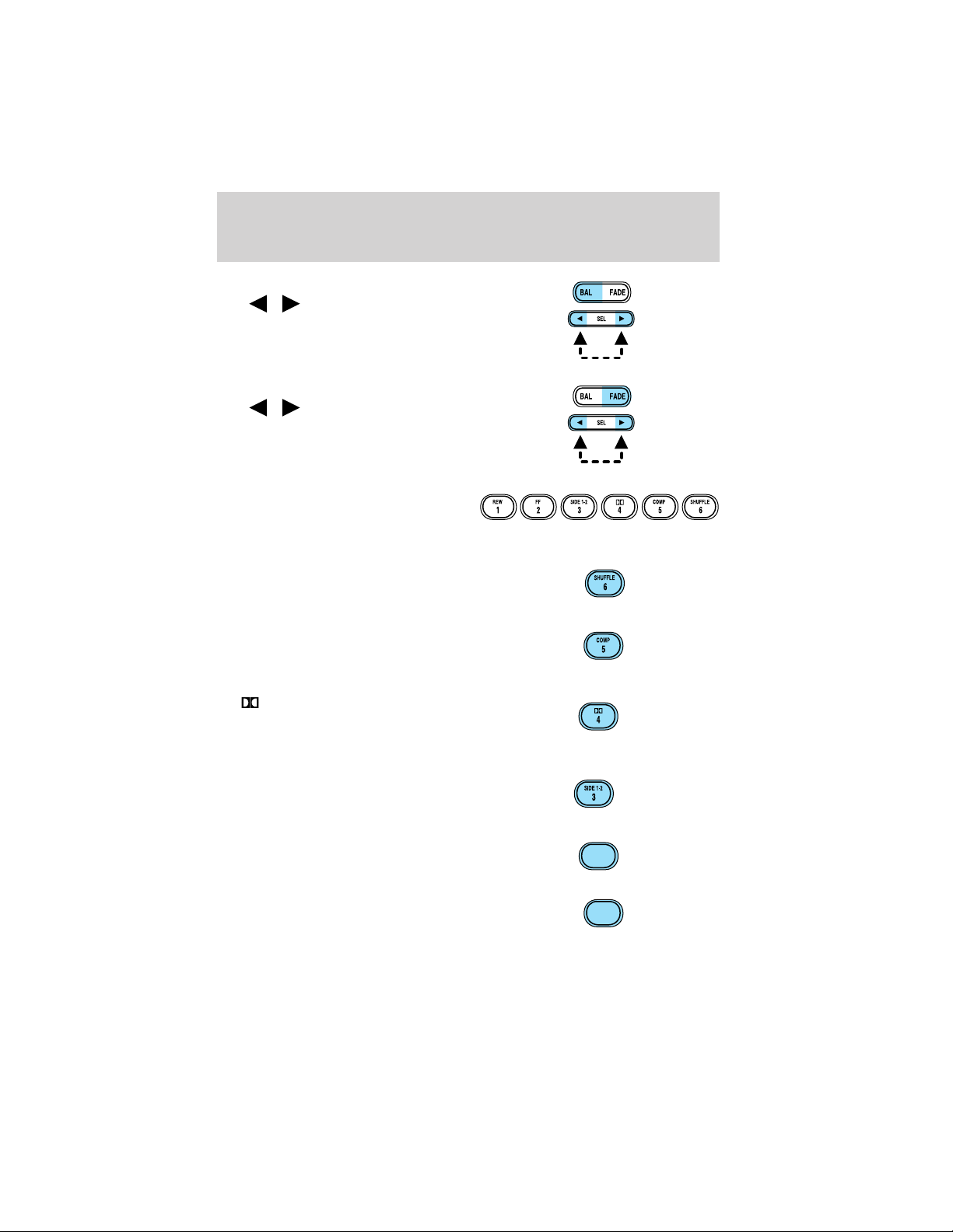
Entertainment Systems
10. Balance: Press BAL; then press
SEL
left/right speakers.
Fade: Press FADE; then press
SEL
rear/front speakers.
11. Memory preset buttons: To
set a station: Select frequency band
AM/FM, tune to a station, press and
hold a preset button until sound returns.
12. Shuffle (CD): Press to play
tracks in random order.
13. Compression (CD): Press to
bring soft and loud passages
together for a more consistent
listening level.
14.
Works in tape mode only. Reduces
tape noise and hiss; press to
activate/deactivate.
15. Side 1–2: Works in tape mode
only. Press to play reverse side of
the tape.
/ to shift sound to the
/ to shift sound to the
Dolby威 noise reduction:
16. Fast Forward (FF): Press for
a slow advance, press and hold for a
fast advance.
17. Rewind (REW): Press for a
slow rewind, press and hold for a
fast rewind.
FF
2
REW
1
23
Page 24
Entertainment Systems
18. Select (SEL): Use with Bass,
Treble, Balance and Fade controls.
19. Bass: Press BASS; then press
SEL
/ to decrease/increase
the bass output.
Treble: Press TREB; then press
SEL
/ to decrease/increase
the treble output.
20. Tune: Works in radio mode only.
Press TUNE
/ to change
frequency down/up.
21. Seek: Press and release
SEEK
/ for previous/next
strong station, selection or track.
SEL
SEEK
TUNE
SEEK
TUNE
22. AM/FM: Press to select
AM/FM1/FM2 frequency band.
24
Page 25
Entertainment Systems
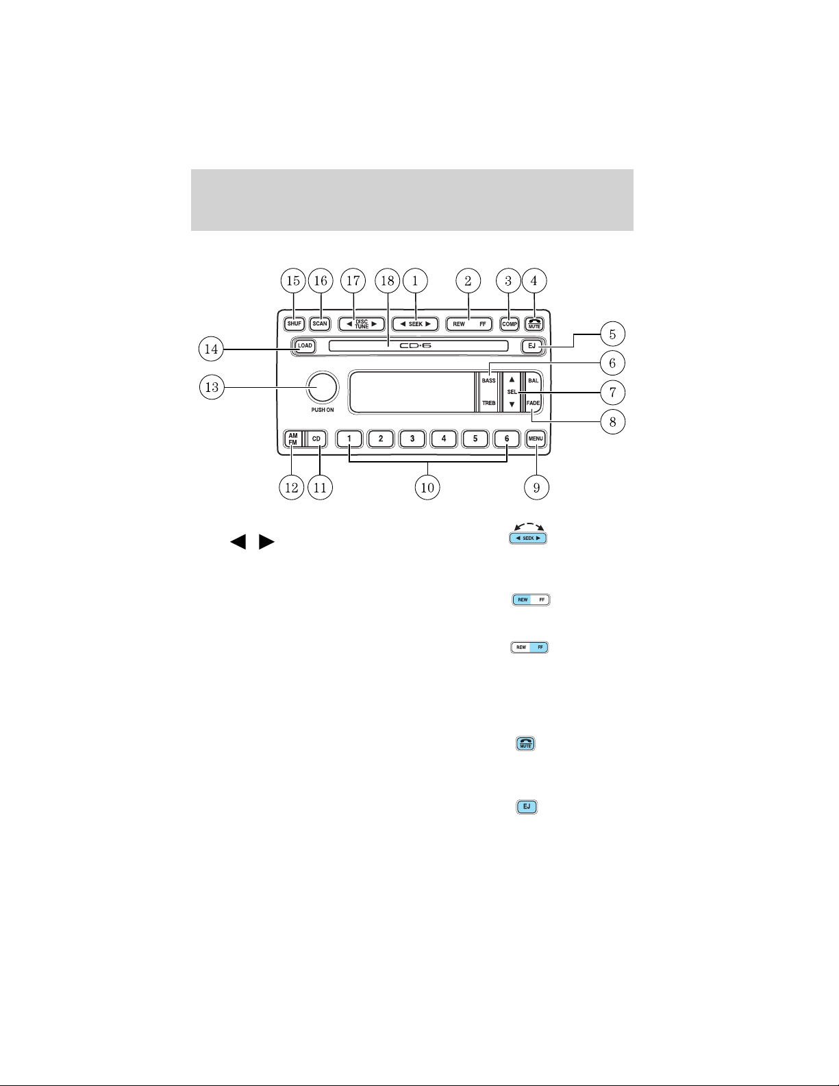
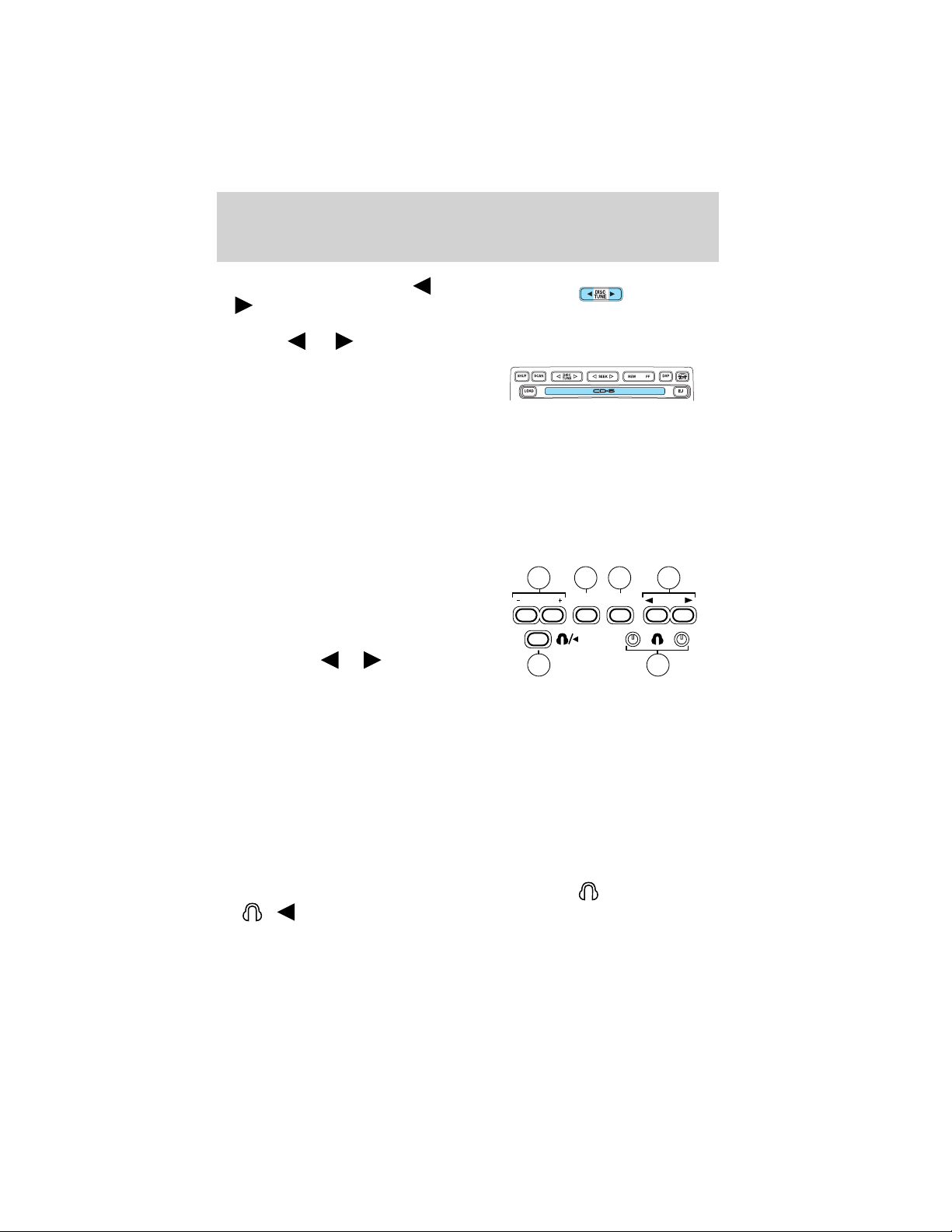
PREMIUM IN-DASH SIX CD SOUND SYSTEM
1. Seek: Press and release
SEEK
strong station, or track of current
disc.
2. Rewind: Press for a slow rewind,
press and hold for a fast rewind.
/ for previous/next
Fast forward: Press for a slow
advance, press and hold for a fast
advance.
3. Comp (Compression): In CD mode, press to adjust the soft and loud
passages together for a more consistent listening level. Press the COMP
control until COMP ON is displayed.
4. Mute: Press to MUTE playing
media; press again return to playing
media. In CD mode, MUTE acts as a
pause feature.
5. Eject: Press to eject a CD. Press
and hold to auto eject all loaded
discs.
25
Page 26
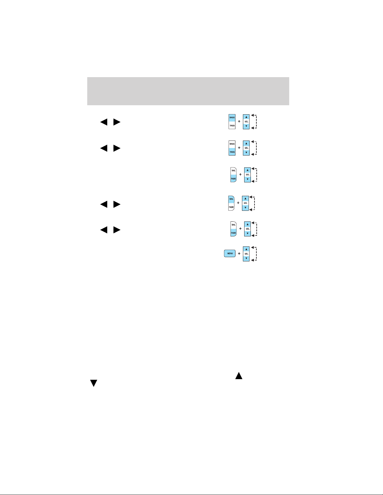
Entertainment Systems
6. Bass: Press BASS; then press
SEL
the bass output.
Treble: Press TREB; then press
SEL
the treble output.
7. Select: Use with Bass, Treble,
Balance and Fade controls to adjust
levels. Use with MENU to set the
clock and engage RDS.
8. Balance: Press BAL; then press
SEL
left/right speakers.
Fade: Press FADE; then press
SEL
rear/front speakers.
9. Menu: Press MENU and SEL to
access clock mode, RDS on/off,
Traffic, Program type, Show type
and Compression modes.
Traffic: Allows you to hear traffic broadcasts. With the feature ON, press
SEEK or SCAN to find a station broadcasting a traffic report (if it is
broadcasting RDS data). Traffic information is not available in most
U.S. markets.
FIND Program type: Allows you to search RDS-equipped stations for a
certain category of music format: Classic, Country, Info, Jazz, Oldies,
R&B, Religious, Rock, Soft, Top 40.
Show TYPE: Displays the station’s format (i.e., Jazz, Classic, Country,
Info, Oldies, R&B, Religious, Rock, Soft and Top 40).
Show NAME: Displays station’s call letters.
Show NONE: Nothing appears in the display.
Compression: Brings soft and loud CD passages together for a more
consistent listening level.
Setting the clock: Press MENU until SELECT HOUR or SELECT
MINUTE is displayed. Use SEL to manually increase (
(
/ to decrease/increase
/ to decrease/increase
/ to shift sound to the
/ to shift sound to the
) or decrease
) the hours/minutes. Press MENU again to disengage clock mode.
26
Page 27
Entertainment Systems
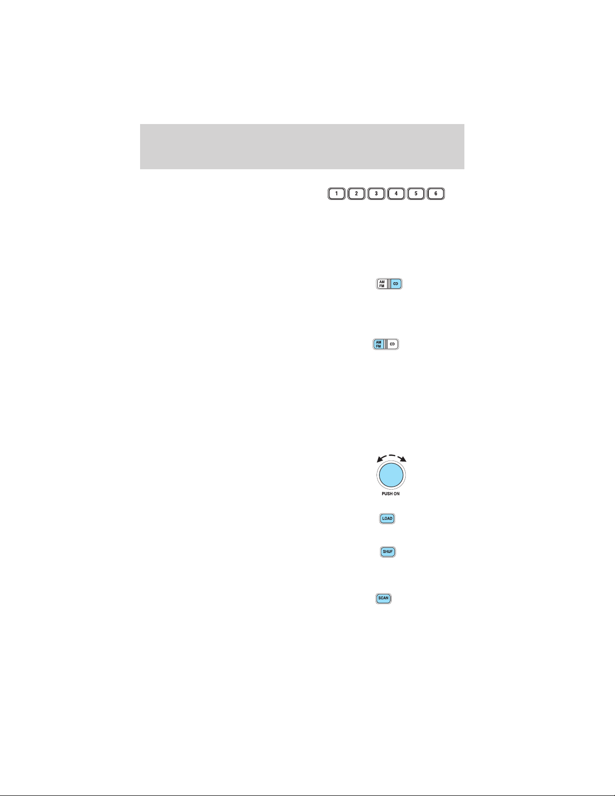
10. Memory presets: To set a
station: Select frequency band
AM/FM; tune to a station, press and
hold a preset button until sound
returns. In CD mode, press to move between CDs.
This radio is equipped with six station memory preset controls which
allow you to set up to six AM stations and 12 FM stations (six in FM1
and six in FM2).
11. CD: Press to select CD mode.
Seamless play: In CD mode, the
transition between the end of one
CD and the beginning of another will not contain delay time unless SEEK
or a preset control is pressed.
12. AM/FM: Press to select a
frequency band in radio mode.
Autoset: Allows you to set the
strongest local radio stations without losing your original manually set
preset stations for AM/FM1/FM2 . Press and momentarily hold AM/FM.
AUTOSET will flash on the display. When the six strongest stations are
filled, the station stored in preset 1 will begin playing. If there are less
than six strong stations, the system will store the last one in the
remaining presets. Press and momentarily hold to disengage (AUTOSET
OFF will appear in the display.).
13. Power/volume: Press to turn
ON/OFF; turn to increase or
decrease volume levels.
14. Load: Press to load a CD. Press
and hold to load up to six discs.
15. Shuffle: Press to play tracks in
random order. Press SHUF to cycle
through SHUF DISC, SHUF TRAC or
SHUF OFF.
16. Scan: Press to hear a brief
sampling of all listenable stations or
CD tracks. Press again to stop.
27
Page 28
Entertainment Systems
17. Disc/Tune: Radio: Press
or to manually tune down or up
the frequency band.
CD: Press
18. CD door: Insert a CD label side
up.
REAR AUDIO CONTROLS (IF EQUIPPED)
The Personal Audio System allows the rear seat passengers to listen to
one media source (radio, tape, CD, or CD changer if equipped) while the
front seat passengers listen to another. However, front and rear seat
passengers can not listen to two different radio stations simultaneously.
To engage, simultaneously press the memory preset controls 3 and 5.
Press again to disengage.
1. Memory: Push successively to
allow rear seat passengers to scroll
through memory presets. Push in
CD changer mode (if equipped) to
advance to the next disc.
2. Seek: Press
the previous or next station,
selection or track.
3. Headphone jack: Plug a 3.5 mm headphone into the jack.
4. Headphone/speaker: Press to turn all speakers off (headphone
mode). Press again to deactivate the headphone and activate system
speakers.
5. Volume: Press + to increase and — to decrease volume levels. From
the rear seat controls, volume can not be set higher than the front seat
setting.
6. Media: Push to toggle between AM, FM1, FM2, tape, CD or CD
changer mode (if equipped).
Plug a 3.5 mm headphone into either one of the two
the
/ control to operate the headphones.
The rear speakers will cut out once the speaker on/off control is pressed.
A soft audible sound may be heard from the rear speakers. The front
or to select the previous or next track on the CD.
or to access
5
VOLUME MEDIA
4
MEM
2631
SEEK
jacks. Press
28
Page 29

Entertainment Systems
speaker will remain playing for the front passengers. Press the /
control again to deactivate the headphones (Personal Audio System).
RADIO FREQUENCIES
AM and FM frequencies are established by the Federal Communications
Commission (FCC) and the Canadian Radio and Telecommunications
Commission (CRTC). Those frequencies are:
AM - 530, 540–1700, 1710 kHz
FM- 87.7, 87.9–107.7, 107.9 MHz
RADIO RECEPTION FACTORS
There are three factors that can effect radio reception:
• Distance/strength: The further you travel from an FM station, the
weaker the signal and the weaker the reception.
• Terrain: Hills, mountains, tall buildings, power lines, electric fences,
traffic lights and thunderstorms can interfere with your reception.
• Station overload: When you pass a broadcast tower, a stronger signal
may overtake a weaker one and play while the weak station frequency
is displayed.
CASSETTE/PLAYER CARE
Do:
• Use only cassettes that are 90 minutes long or less.
• Tighten very loose tapes by inserting a finger or pencil into the hole
and turning the hub.
• Remove loose labels before inserting tapes.
• Allow tapes which have been subjected to extreme heat, humidity or
cold to reach a moderate temperature before playing.
• Clean the cassette player head with a cassette cleaning cartridge after
10–12 hours of play to maintain good sound/operation.
Don’t:
• Expose tapes to direct sunlight, extreme humidity, heat or cold.
• Leave tapes in the cassette player for a long time when not being
played.
29
Page 30

Entertainment Systems
CD/CD PLAYER CARE
Do:
• Handle discs by their edges only. Never touch the playing surface.
• Inspect discs before playing. Clean only with an approved CD cleaner
and wipe from the center out.
Don’t:
• Expose discs to direct sunlight or heat sources for extended periods
of time.
• Insert more than one disc into each slot of the CD changer magazine.
• Clean using a circular motion.
CD units are designed to play commercially pressed 12 cm (4.75
in) audio compact discs only. Due to technical incompatibility,
certain recordable and re-recordable compact discs may not
function correctly when used in Ford CD players. Irregular
shaped CDs, CDs with a scratch protection film attached, and CDs
with homemade paper (adhesive) labels should not be inserted
into the CD player. The label may peel and cause the CD to
become jammed. It is recommended that homemade CDs be
identified with permanent felt tip marker rather than adhesive
labels. Ball point pens may damage CDs. Please contact your
dealer for further information.
AUDIO SYSTEM WARRANTY AND SERVICE
Refer to the Warranty Guide for audio system warranty information. If
service is necessary, see your dealer or qualified technician.
30
Page 31

Climate Controls
HEATER ONLY SYSTEM (IF EQUIPPED)
1. Air flow selections: Controls
the direction of the airflow in the
vehicle. See the following for a brief
description on each control.
: Distributes outside air through
the instrument panel vents.
O (OFF): Outside air is shut out
and the fan will not operate.
: Distributes outside air through
the instrument panel vents and the
floor vents.
: Distributes outside air through the floor vents.
: Distributes outside air through the windshield defroster vents and
floor vents.
: Distributes outside air through the windshield defroster vents.
2. Temperature selection: Controls the temperature of the airflow in
the vehicle.
3. Fan speed adjustment: Controls the volume of air circulated in the
vehicle.
Operating tips
• To reduce fog build up on the windshield during humid weather, place
the air flow selector in the
• To reduce humidity build up inside the vehicle during cold or warm
weather, do not drive with the air flow selector in the OFF position.
• Under normal weather conditions, do not leave the air flow selector in
OFF when the vehicle is parked. This allows the vehicle to “breathe”
using the outside air inlet vents.
• Do not put objects under the front seats that will interfere with the air
flow to the back seats.
• Remove any snow, ice or leaves from the air intake area at the base of
the windshield.
To aid in side window defogging/demisting in cold weather:
1. Select
2. Set the temperature control to full heat
position.
3
1
2
31
Page 32

Climate Controls
3. Set the fan speed to HI
4. Direct the outer instrument panel vents towards the side windows
To increase airflow to the outer instrument panel vents, close the vents
located in the middle of the instrument panel.
Do not place objects on top of the instrument panel as these
objects may become projectiles in a collision or sudden stop.
MANUAL HEATING AND AIR CONDITIONING SYSTEM
(IF EQUIPPED)
1. Air flow selections: Controls
the direction of the airflow in the
vehicle. See the following for a brief
description on each control.
MAX A/C: Uses recirculated air
through the instrument panel
registers to cool the vehicle. This
mode is more noisy than A/C, but is
more economical and efficient. May
reduce undesirable odors from
entering the vehicle.
: Distributes outside air through the instrument panel vents.
O (OFF): Outside air is shut out and the fan will not operate.
: Distributes outside air through the instrument panel vents and the
floor vents.
: Distributes outside air through the floor vents.
5
4
3
1
MAX
A/C
A/C
2
: Distributes outside air through the windshield defroster vents and
floor vents.
: Distributes outside air through the windshield defroster vents.
2. A/C: Uses outside air to cool the vehicle. Air flows from the
instrument panel register vents only.
3. Temperature selection: Controls the temperature of the airflow in
the vehicle.
32
Page 33

Climate Controls
4. Rear defrost control: Clears the
rear window of thin ice and fog
when the engine is running.
5. Fan speed adjustment: Controls the volume of air circulated in the
vehicle.
Operating tips
• To reduce fog build up on the windshield during humid weather, place
the air flow selector in the
• To reduce humidity build up inside the vehicle: do not drive with the
air flow selector in the OFF or MAX A/C position.
• Under normal weather conditions, do not leave the air flow selector in
MAX A/C or OFF when the vehicle is parked. This allows the vehicle
to “breathe” using the outside air inlet vents.
• Do not put objects under the front seats that will interfere with the
airflow to the back seats.
• Remove any snow, ice or leaves from the air intake area at the base of
the windshield.
To aid in side window defogging/demisting in cold weather:
1. Select
2. Select A/C
3. Modulate the temperature control to maintain comfort.
4. Set the fan speed to HI
5. Direct the outer instrument panel vents towards the side windows
To increase airflow to the outer instrument panel vents, close the vents
located in the middle of the instrument panel.
position.
Do not place objects on top of the instrument panel as these
objects may become projectiles in a collision or sudden stop.
33
Page 34

Climate Controls
MANUAL HEATING AND AIR CONDITIONING SYSTEM WITH REAR
PASSENGER COMPARTMENT CLIMATE CONTROL SYSTEM
(IF EQUIPPED)
1. Air flow selections: Controls
the direction of the airflow in the
5
6
vehicle. See the following for a brief
description on each control.
MAX A/C: Uses recirculated air
OFF
through the instrument panel
REAR CTL
registers to cool the vehicle. This
mode is more noisy than A/C, but is
more economical and efficient. May
4
reduce undesirable odors from
entering the vehicle.
: Distributes outside air through the instrument panel vents.
O (OFF): Outside air is shut out and the fan will not operate.
: Distributes outside air through the instrument panel vents and the
floor vents.
: Distributes outside air through the floor vents.
: Distributes outside air through the windshield defroster vents and
floor vents.
: Distributes outside air through the windshield defroster vents.
2. A/C: Uses outside air to cool the vehicle. Air flows from the
instrument panel register vents only.
3. Rear temperature selection: Controls the temperature of the
airflow in the rear of the vehicle when the unit is operating and the rear
occupants do not have control.
4. Rear defrost control: Clears the
rear window of thin ice and fog
when the engine is running.
5. Fan speed adjustment: Controls the volume of air circulated in the
vehicle.
6. Front temperature selection: Controls the temperature of the
airflow in the front of the passenger compartment.
7. Rear passenger compartment: Turns on the auxilary climate control
system, adjust rear blower speed and in “REAR CTL” setting allows
control to the rear occupants.
FRONT
REAR
3
7
1
MAX
A/C
A/C
2
34
Page 35

Climate Controls
When the front control slider bar is
in the “REAR CTL” position:
1. Fan speed adjustment: Allows
rear passengers to control the
volume of air that is distributed
from the rear registers..
2. Temperature/mode selection:
The distribution of air from the
overhead and floor registers is based on the temperature selected.
REAR WINDOW DEFROSTER
The rear defroster control is located
on the instrument panel. The
ignition switch must be in the ON
position to operate the rear defroster.
Press the control to turn the defroster ON/OFF. A small LED will
illuminate when the rear defroster is ON.
The defroster automatically turns off after 10 minutes or when the
ignition it turned to the OFF position.
CABIN AIR FILTER (IF EQUIPPED)
Your vehicle may be equipped with a Cabin air filter. The cabin air filter
restricts the entry of airborne dust and pollen particles. The filter is
located just in front of the windshield under the cowl vent screen on the
passenger side of the vehicle.
For more information, or to replace the filter, see your Ford, Lincoln or
Mercury Dealer.
35
Page 36

Lights
HEADLAMP CONTROL
Turns the lamps off.
Turns on the parking
lamps, instrument panel lamps,
license plate lamps and tail lamps.
Turns the headlamps on.
Autolamp control (if equipped)
The autolamp system provides light
sensitive automatic on-off control of
the exterior lights normally
controlled by the headlamp control.
The autolamp system also keeps the
lights on for a fixed period of time
after the ignition switch is turned to
OFF.
• To turn autolamps on, rotate the
control counterclockwise.
• To turn autolamps off, rotate the control clockwise to OFF.
AUTO
Daytime running lamps (DRL) (if equipped)
Turns the lowbeam headlamps on with a reduced output. To activate:
• the key must be in the ON position,
• the headlamp control is in the OFF, parking lamps or autolamp
position.
Always remember to turn on your headlamps at dusk or during
inclement weather. The Daytime Running Light (DRL) System
does not activate your tail lamps and generally may not provide
adequate lighting during these conditions. Failure to activate your
headlamps under these conditions may result in a collision.
36
Page 37

Lights
High beams
Push the lever toward the
instrument panel to activate. Pull
the lever towards you to deactivate.
Flash to pass
Pull toward you slightly to activate
and release to deactivate.
Battery saver
The battery saver will shut off the exterior lamps 10 minutes after the
ignition control has been turned off and the headlamp control is in the
HEADLAMP position. The system will not turn off the parking lamps if
the headlamp control is in the PARK position. For interior lights, refer to
Illuminated entry in the Locks and security chapter.
PANEL DIMMER CONTROL
Use to adjust the brightness of the
instrument panel lighting during
headlamp and parklamp operation.
• Rotate control to full up position
to turn on all interior lights.
• Rotate control to next position
(adjustment dial) and move up
and down to adjust the
instrument panel lights.
• Rotate to the first or second
lower detent position to turn on the instrument panel lights to full
brightness.
37
Page 38

Lights
This control also has other features that are activated when any door is
opened:
• Rotate to full up position or next position (adjustment dial) to turn on
all interior lights.
• Rotate to first lower detent position to activate “sleeping baby
mode”— dome lamps will remain off and only the lower lamps will
illuminate.
• The second lower detent position (full down) will shut off all interior
lights.
The dome lamp will not illuminate if the control switch is in the OFF
position.
AIMING THE HEADLAMPS
The headlamps on your vehicle are properly aimed at the assembly plant.
If your vehicle has been in an accident the alignment of your headlamps
should be checked by a qualified service technician.
You will need one E8 Torx socket to make the adjustments.
Vertical aim adjustment
1. Park the vehicle on a level surface approximately 7.6 meters (25 feet)
from a vertical wall or screen directly in front of it.
• (1) Eight feet
• (2) Center height of lamp to
ground
• (3) Twenty five feet
• (4) Horizontal reference line
2. Measure the height from the center of your headlamp to the ground
and mark a 2.4 meter (8 foot) horizontal reference line on the vertical
wall or screen at this height (a piece of masking tape works well). The
center of the lamp is marked by a 3.0 mm circle on the headlamp lens.
3. Turn on the low beam headlamps to illuminate the wall or screen and
open the hood.
38
Page 39

Lights
4. On the wall or screen you will
observe a light pattern with high
intensity flat segments at the top
edge of the pattern. If the flat edges
are not at the horizontal reference
line, the beam will need to be
adjusted.
5. Locate the vertical adjuster on
each headlamp, then use an E8 Torx
socket to turn the adjuster either counterclockwise (to adjust up) or
clockwise (to adjust down) positioning the horizontal edge of the high
intensity light on the horizontal reference line.
6. HORIZONTAL AIM IS NOT REQUIRED FOR THIS VEHICLE AND IS
NON-ADJUSTABLE.
7. Close the hood and turn off the lamps.
TURN SIGNAL CONTROL
• Push down to activate the left
turn signal.
• Push up to activate the right turn
signal.
INTERIOR LAMPS
Dome lamps (if equipped)
The front dome lamp is located overhead between the driver and
passenger seats.
The dome lamp will stay on if the
control is moved to the passenger
side position. When the control is in
the middle position, the lamp will
only come on when a door is
opened. If the control is moved to
the driver’s side position, the lamp
will not come on at all.
The dome lamp will illuminate whenever a front door is opened. If either
front door has been opened from the outside, the lamp will remain on for
39
Page 40

Lights
15 seconds after the door is shut. If any other door has been opened
from the inside, the lamp will shut off immediately after the door is
closed.
Map lamps (if equipped)
The map lamps and controls are
located on the dome lamp. Press the
controls on either side of each map
lamp to activate the lamps.
Rear dome lamp
The dome lamp lights when:
• any door is opened (and switch is
in middle position).
• the instrument panel dimmer
switch is held up until the
courtesy lamps come on.
• any of the remote entry controls
are pressed and the ignition is OFF (and switch is in the middle
position).
With the ignition key in the ACC or ON position, the rear dome lamp can
be turned ON or OFF by sliding the control.
Rear courtesy/reading lamps (if equipped)
The courtesy lamp lights can be
turned on with rocker switch at any
time.
40
Page 41

Lights
BULBS
Replacing exterior bulbs
Check the operation of all the bulbs frequently.
Using the right bulbs
Replacement bulbs are specified in the chart below. Headlamp bulbs
must be marked with an authorized “D.O.T.” for North America and an
“E” for Europe to assure lamp performance, light brightness and pattern
and safe visibility. The correct bulbs will not damage the lamp assembly
or void the lamp assembly warranty and will provide quality bulb burn
time.
Function Trade Number
Front park/turn lamps 3157 AK (amber)
Cornering lamps 3156K
Auxiliary parking lamps 912
Headlamps 9007
Rear license plate lamps 168
High-mount brake lamp 921
Rear turn lamps 3156K
Backup lamps 3156K
Brake/tail lamps 3157K
Dome lamp 921
Cargo liftgate lamp T-562
Map lamps/dome 578 (opt)
Stepwell lamp T-562
Front seat footwell 194
Front door mounted courtesy lamp 168
Second row reading lamp 578
All replacement bulbs are clear in color except where noted.
To replace all instrument panel lights - see your dealer.
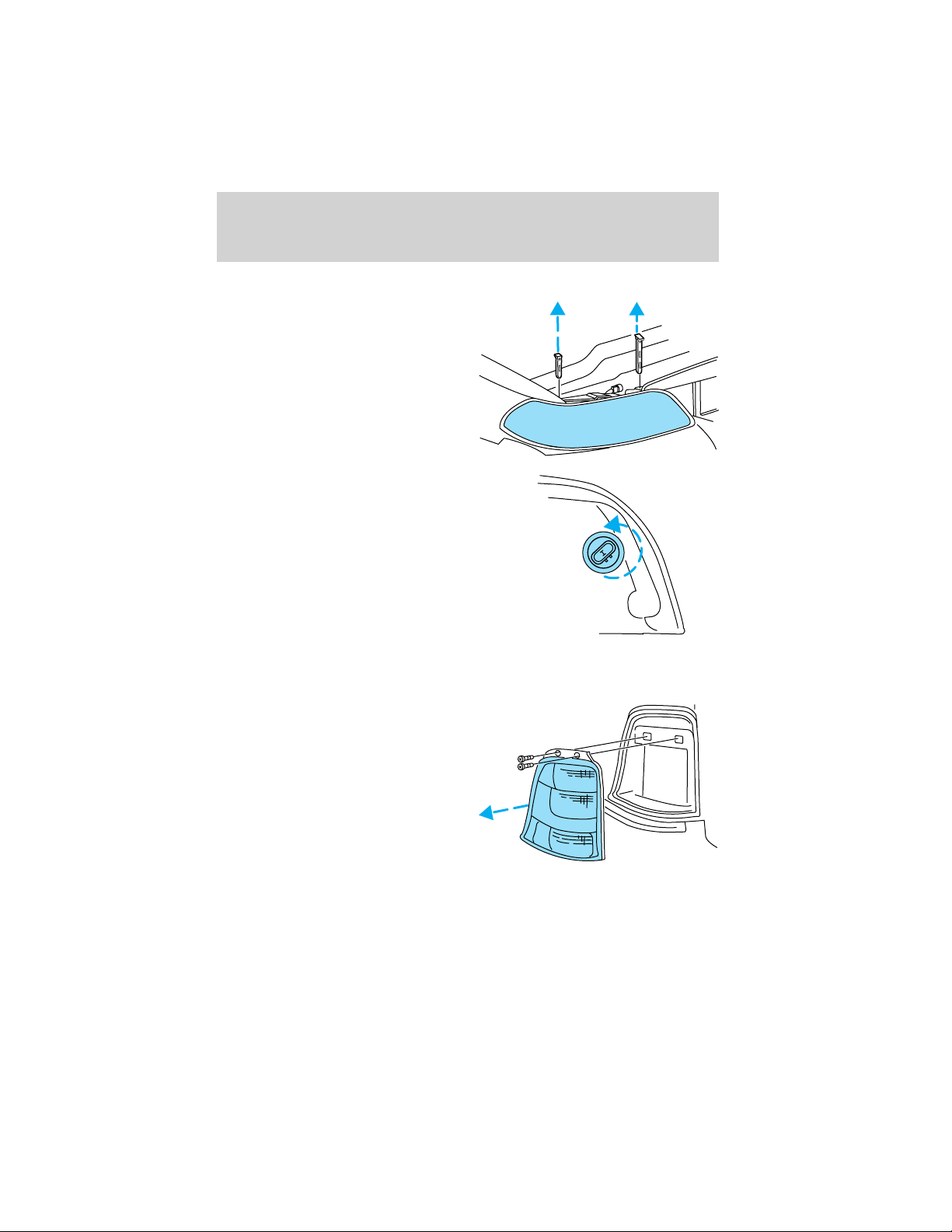
Replacing headlamp bulbs
To remove the headlamp bulb:
1. Make sure headlamp switch is in the OFF position, then open the
hood.
41
Page 42

Lights
2. Pull the two retainer pins up to
release the headlamp assembly and
pull headlamp assembly forward to
expose the back of the bulb.
3. Disconnect the electrical
connector from the bulb by pulling
rearward and remove the retaining
ring by rotating it counterclockwise,
then slide it off the plastic base.
4. Pull the bulb straight out of the
lamp assembly.
Handle a halogen headlamp bulb carefully and keep out of
children’s reach. Grasp the bulb only by its plastic base and do
not touch the glass. The oil from your hand could cause the bulb to
break the next time the headlamps are operated.
Install the new bulb in reverse order.
42
Page 43
Replacing front parking/turn signal bulbs
1. Make sure the headlamp switch is
in the OFF position and open the
hood.
2. Pull the two headlamp retainer
pins up to release the headlamp
assembly, then pull the headlamp
assembly forward to expose the bulb
socket.
3. Remove bulb socket by turning it
counterclockwise, and pull the bulb
straight out of the socket.
Install the new bulb(s) in reverse order.
Replacing tail lamp/backup/turn lamp bulbs
1. Make sure the headlamp switch is
in the OFF position and open the
liftgate to expose the tail lamp
assembly, then remove the retaining
screws for the lamp assembly.
2. Carefully remove the lamp
assembly.
3. Rotate bulb socket
counterclockwise and remove from
lamp assembly.
4. Pull bulb straight out of socket and push in new bulb.
Install the new bulb(s) in reverse order.
Lights
43
Page 44

Lights
Replacing license plate lamp bulbs
1. Make sure the headlamp is in the
OFF position and remove two
screws and the license plate lamp
assembly from the liftgate.
2. Remove bulb socket by pulling it
straight out of the lamp assembly.
3. Carefully pull the bulb out from
the socket.
Install the new bulb(s) in reverse order.
Replacing high-mount brakelamp bulbs
1. Open liftgate and gently pry the
access cover off the liftgate trim
panel.
2. Rotate the bulb socket
counterclockwise and remove.
3. Carefully pull bulb straight out.
Install the new bulb(s) in reverse order.
Replacing cornering lamp bulbs (if equipped)
For bulb replacement, see a dealer or qualified technician.
Replacing auxiliary parking lamp bulbs (if equipped)
For bulb replacement, see a dealer or qualified technician.
44
Page 45
Driver Controls
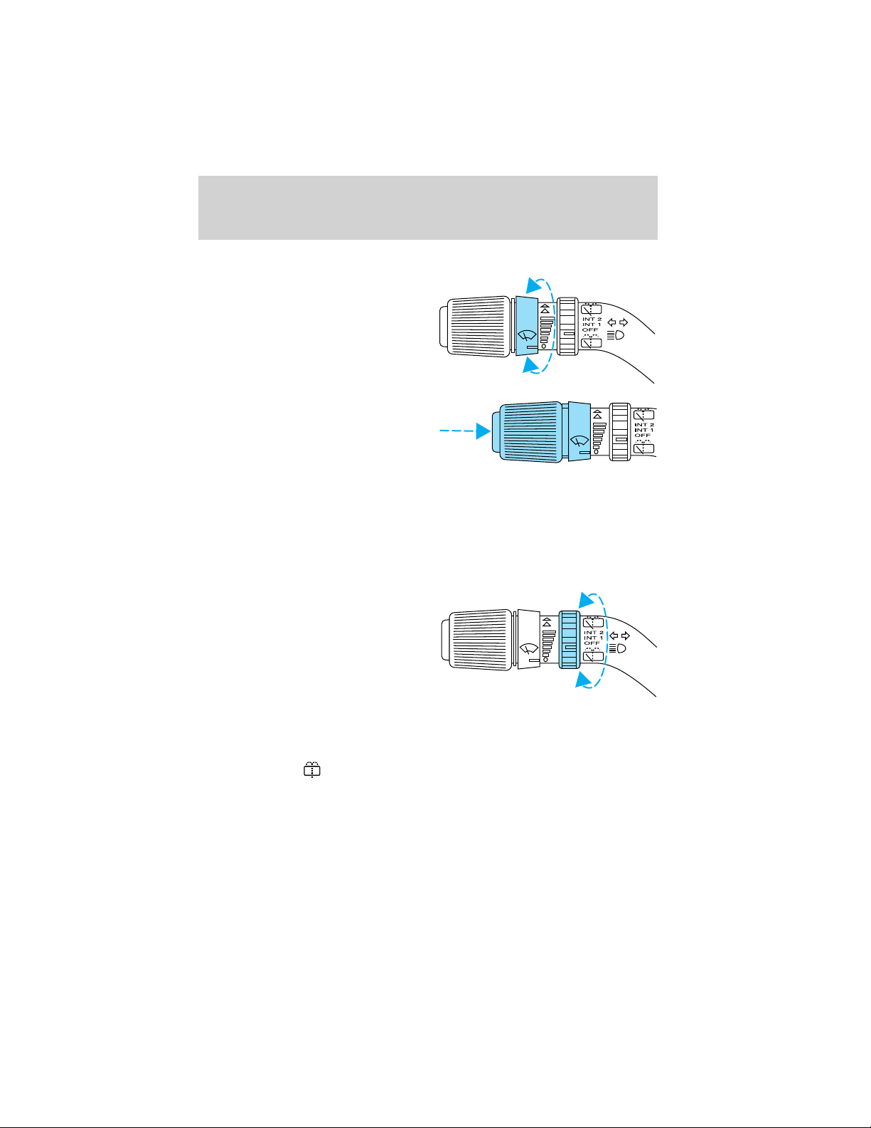
MULTI-FUNCTION LEVER
Windshield wiper: Rotate the end
of the control away from you to
increase the speed of the wipers;
rotate towards you to decrease the
speed of the wipers.
Windshield washer: Push the end
of the stalk:
• briefly: causes a single swipe of
the wipers without washer fluid.
• a quick push and hold: the wipers
will swipe three times with
washer fluid.
• a long push and hold: the wipers and washer fluid will be activated for
up to ten seconds.
Rear window wiper/washer controls
For rear wiper operation, rotate the
rear window wiper and washer
control to the desired position.
Select:
INT 2 — One second interval rear
wiper.
INT 1 — Ten second interval rear
wiper.
OFF — Rear wiper and washer off.
For rear wash cycle, rotate (and hold as desired) the rear wiper/washer
control to either
From either position, the control will automatically return to the INT2 or
OFF position.
position.
45
Page 46
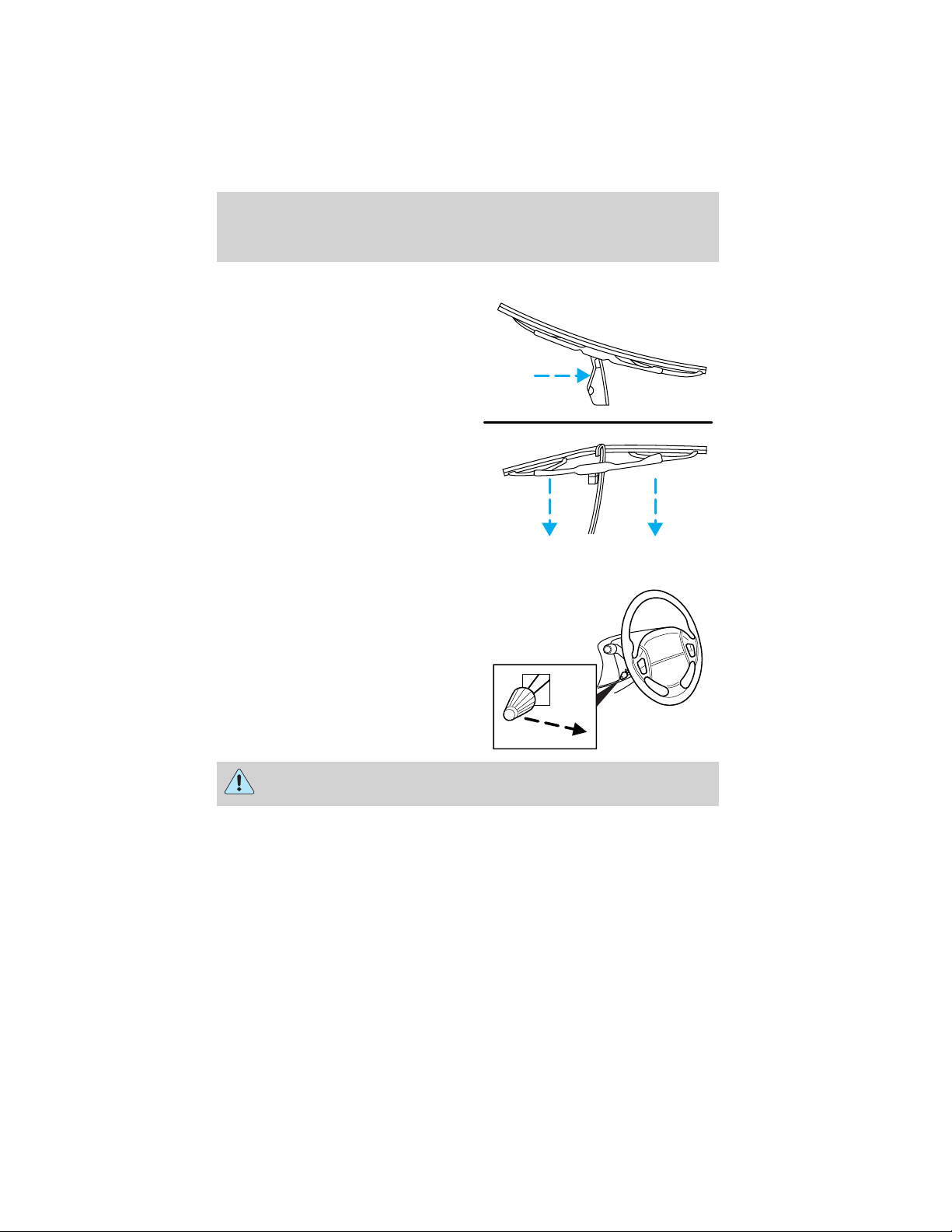
Driver Controls
Changing the wiper blades
1. Pull the wiper arm away from the
vehicle. Turn the blade at an angle
from the wiper arm. Push the lock
pin manually to release the blade
and pull the wiper blade down
toward the windshield to remove it
from the arm.
2. Attach the new wiper to the
wiper arm and press it into place
until a click is heard.
3. Replace wiper blades every 6
months for optimum performance.
TILT STEERING WHEEL
To adjust the steering wheel:
1. Pull and hold the steering wheel
release control toward you.
2. Move the steering wheel up or
down until you find the desired
location.
3. Release the steering wheel
release control. This will lock the
steering wheel in position.
46
Never adjust the steering wheel when the vehicle is moving.
Page 47

Driver Controls
ILLUMINATED VISOR MIRROR (IF EQUIPPED)
Lift the mirror cover to turn on the
visor mirror lamps.
OVERHEAD CONSOLE (IF EQUIPPED)
The appearance of your vehicle’s overhead console will vary according to
your option package.
Forward storage bins and conversation mirror (if equipped)
The storage compartments may be
used to store sunglasses or similar
objects. The conversation mirror
allows the driver to view the rear
seating area.
This does not replace the
rear view mirror.
Refer to Power Sliding Doors
(PSD)(if equipped) in this chapter for operation of doors.
47
Page 48

Driver Controls
Installing a garage door opener (if equipped)
The storage compartment can be converted to accommodate a variety of
aftermarket garage door openers:
• Remove the storage clip from the
aftermarket transmitter.
• Place Velcro hook onto side of
aftermarket transmitter opposite
of actuator control.
• Place the transmitter into storage
compartment, control down.
• Place the provided height
adaptors onto the back of the
GARAGE control as needed.
• Press the GARAGE control to
activate the transmitter.
Manual Sliding Door (if equipped)
Manual door operation
With the door unlocked, unlatch the door using the inside or outside
handle.
Note: Before unlatching the left side door, verify that the fuel fill door is
closed. The left hand door will not open if the fuel door is open.
Slide the door carefully in a controlled manner to the full open position.
At the end of travel, firmly push the door against the bump stop to
engage the hold open mechanism to restrain the door. When operating
the door on a gradient, special care should be taken to manually control
the opening and closing speed of the door.
If the door is allowed to slide open or closed unrestrained, injury
to personnel or damage to the door could result.
When closing the sliding door, keep the head, hands and other body
parts of vehicle occupants out of the path of the closing door. Slide the
door closed in a careful, controlled manner.
48
Page 49

Driver Controls
When closing the sliding doors, you should verify they are free of
obstructions and ensure that children and/or pets are not in the
proximity of the sliding door openings. Injury could result if body parts
are caught or pinched in an uncontrolled sliding door.
Manual door operation when vehicle is stopped or parked on a
downhill grade
In some cases it may be necessary
to have someone hold the door
while rear seat passengers are
entering or exiting the vehicle. The
hold open mechanism will restrain
the door open when the vehicle is
parked on moderate downhill
grades. On more severe grades,
the operator should ensure that
the open door is stable and
secure against the stop, before
allowing passengers to enter or exit the vehicle or before
loading/unloading cargo.
Vehicle operation with the door in the open position is not
recommended. Abrupt vehicle acceleration or deceleration could cause
the door to move suddenly and could result in injury or damage to the
door.
If the vehicle is parked on a downhill grade, the door could slam
shut and could result in injury or damage to the door. Ensure
that the open door is secure against the stop before allowing
passengers to enter or exit the vehicle.
Power Sliding Door (PSD) (if equipped)
With this option, you can open and close the sliding door(s) with the
controls inside your vehicle. With the remote keyless entry system, you
can also operate the PSD with the remote transmitter. Refer to Remote
Entry System in the Locks and security chapter.
49
Page 50

Driver Controls
The PSD feature has control(s)
accessible by passengers in the
second row seating positions. The
control(s) are located on the trim
panel in front of the sliding door.
Press and release the control to
open the PSD on either side of the
vehicle.
When closing the sliding doors, you should verify they are free of
obstructions and ensure that children and/or pets are not in the
proximity of the sliding door openings. Injury could result if body parts
are caught or pinched in an uncontrolled sliding door.
To disable
Press the OFF control in the
overhead console to turn off the
PSD. This prevents opening the PSD
using the rear seat control(s), but
the door(s) can be opened manually
with the handle. With the child
safety lock engaged, only the
outside handle will open the door.
The controls in the overhead console and the Remote Entry System will
remain functional with the system shut OFF.
Opening and closing the PSD
The sliding door must be unlocked for it to operate. The key does not
have to be in the ignition. To help avoid accidental operation of the
Power Sliding Door, disable the PSD second row passenger controls.
When the key is in the ignition in RUN, the PSD will only open if the
transaxle is in PARK (P). The transaxle does not have to be in PARK (P)
to close the door.
50
Page 51

Driver Controls
With the ON/OFF control in the ON
position, either sliding door can be
opened or closed by:
• pushing and releasing the
overhead console right or left
hand control
• pushing and releasing the right or
left hand second row passenger
control
• manually pulling the inside or outside sliding door handle and release
• operating the remote transmitter. Refer to Remote Entry System in
the Locks and security chapter.
The door will open or close fully using these options.
With the ON/OFF control in the OFF position, either sliding door can be
operated by pulling the inside or outside handle and sliding the door
back manually. If the vehicle is stopped or parked on a downhill grade,
refer to Manual sliding door in this chapter for more information.
If the vehicle is parked on a
downhill grade, the door
could slam shut and could result
in injury or damage to the door.
Ensure that the open door is
secure against the stop before
allowing passengers to enter or
exit the vehicle.
The left hand PSD will not open (manually or power) if the fuel door is
open regardless of the ON/OFF control position.
Safety/Obstructions
If anything obstructs the Power Sliding Door while it is closing, the door
will automatically reverse to the open position, provided it meets
sufficient resistance.
Resetting the PSD
The power sliding door may operate incorrectly or not at all because of
the following conditions:
• a low voltage or dead battery
51
Page 52

Driver Controls
• disconnecting the battery
• if the PSD fuse (fuse #6) is removed or blown. Refer to Fuses and
relays in the Roadside emergencies chapter.
If any of the above conditions has occured, preform the following steps
to reset the PSD:
1. Check to see if PSD is unlocked and securely closed.
2. Make sure the gearshift is in (P) Park.
3. Push the PSD control on the overhead console to open the door.
4. Wait five (5) seconds and close the door by pressing the PSD control
on the overhead console.
5. Wait five (5) seconds and repeat Steps 3 and 4 then go on to step 6.
6. Repeat steps 3–5 for opposite door.
If the door does not rest in the fully open position, repeat Steps 1–4
again. If the door still does not operate correctly:
7. Turn the ignition switch to OFF.
8. Remove the PSD fuse (fuse #6) from the passenger fuse panel and
leave it out for thirty (30) seconds. Refer to Fuses and relays in the
Roadside emergencies chapter.
9. Reinstall the fuse and wait ten (10) seconds.
10. Repeat steps 1–6 above.
If the door still does not operate correctly, see your dealer for service.
Sliding Door Child Safety Lock
Your vehicle is equipped with a sliding door child safety lock that helps
prevent passengers from operating the sliding door by using the inside
door handle, refer to Child safety locks in the Locks and Security
chapter.
To open the sliding door when the child safety lock is on:
• Unlock the sliding door and open the door from the outside.
• Press the right or left hand control on the overhead console to open
the door.
AUXILIARY POWER POINT
Power outlets are designed for accessory plugs only. Do not hang
any type of accessory or accessory bracket from the plug.
Improper use of the power outlet can cause damage not covered
by your warranty.
52
Page 53

Driver Controls
Do not plug optional electrical accessories into the cigarette lighter. Use
the power point.
Do not use the power point for operating the cigarette lighter element.
The Maximum power each power point can supply depends on the fuse
rating. For example: a 20A fuse should supply a maximum of 240 Watts,
a 15A fuse should supply a maximum of 180 Watts and a 10A fuse should
supply a maximum of 120 Watts. Exceeding these limits will result in a
blown fuse.
Always keep the power point caps closed when not being used.
POWER WINDOWS
When closing the power
windows, you should verify
they are free of obstructions and
ensure that children and/or pets
are not in the proximity of the
window openings.
Press and hold the bottom part of the rocker switch to open the window.
Press and hold the top part of the rocker switch to close the window.
One touch down
Allows the driver’s window to open
fully without holding the control
down. Press completely down on
AUTO and release quickly. Press
again to stop.
Accessory delay
With accessory delay, the window switches may be used for up to ten
minutes after the ignition switch is turned to the OFF position or until
any door is opened.
53
Page 54

Driver Controls
Power vent windows (if equipped)
Your vehicle may be equipped with
rear power vent windows which are
operated the same as the front
power windows.
MIRRORS
Automatic dimming inside rear view mirror (if equipped)
Your vehicle is equipped with an inside rear view mirror which has an
auto-dimming function. The electronic day/night mirror will change from
the normal state to the non-glare state when bright lights (glare) reach
the mirror. When the mirror detects bright light from front or behind, it
will automatically adjust (darken) to minimize glare.
Do not block the sensor on the backside of the mirror since this may
impair proper mirror performance.
Press the control to turn the mirror
OFF or AUTO.
The mirror will automatically return
to the normal state whenever the
vehicle is placed in R
(Reverse)(when the mirror is on) to ensure a bright clear view when
backing up.
OFF AUTO
Power side view mirrors (if equipped)
To adjust your mirrors:
1. Select
to adjust the left
mirror or to adjust the right
mirror.
2. Move the control in the direction
you wish to tilt the mirror.
3. Return to the center position to
lock mirrors in place.
54
Page 55

Driver Controls
Heated outside mirrors (if equipped)
Both mirrors are heated
automatically to remove ice, mist
and fog when the rear window
defrost is activated.
Do not remove ice from the
mirrors with a scraper or
attempt to readjust the mirror
glass if it is frozen in place.
These actions could cause damage to the glass and mirrors.
Signal mirrors (if equipped)
When the turn signal is activated,
the appropriate mirror will show a
blinking yellow arrow. When the
park lamps are on, the blinking
arrow will be dimmer.
The arrow provides an additional
warning to other drivers that your
vehicle is about to turn.
When the sliding door is open, the indicator in the appropriate mirror
will flash indicating people may be entering/exiting the vehicle.
Fold-away mirrors
Pull the side mirrors in carefully
when driving through a narrow
space, like an automatic car wash.
55
Page 56

Driver Controls
POWER ADJUSTABLE FOOT PEDALS (IF EQUIPPED)
The accelerator and brake pedal
should only be adjusted when the
vehicle is stopped and the gearshift
lever is in the P(Park) position.
Press and hold the rocker control to
adjust accelerator and brake pedal
toward you or away from you.
The adjustment allows for approximately 76 mm (3 inches) of maximum
travel.
Never adjust the accelerator and brake pedal with feet on the
pedals while the vehicle is moving.
SPEED CONTROL (IF EQUIPPED)
With speed control set, you can maintain a speed of 48 km/h (30 mph)
or more without keeping your foot on the accelerator pedal. Speed
control does not work at speeds below 48 km/h (30 mph).
If your vehicle is equipped with AdvanceTrac娂 system, the speed control
will automatically disengage when the road conditions change. When
driving conditions permit you can return to speed control by pressing
RES on the speed control. For more information on the AdvanceTrac娂
system see AdvanceTrac娂 Stability Enhancement System section in
the Driving chapter.
Do not use the speed control in heavy traffic or on roads that
are winding, slippery or unpaved.
Setting speed control
The controls for using your speed
control are located on the steering
wheel for your convenience.
1. Press the ON control and release
it.
2. Accelerate to the desired speed.
56
OFF
ON
Page 57

Driver Controls
3. Press the SET + control and
release it.
4. Take your foot off the accelerator
pedal.
5. The indicator
instrument cluster will turn on.
Note:
• Vehicle speed may vary momentarily when driving up and down a
steep hill.
• If the vehicle speed increases above the set speed on a downhill, you
may want to apply the brakes to reduce the speed.
• If the vehicle speed decreases more than 16 km/h (10 mph) below
your set speed on an uphill, your speed control will disengage.
• If the vehicle speed decreases to 40 km/h (25 mph) or less, your
speed control will disengage
Disengaging speed control
To disengage the speed control:
• Depress the brake pedal
Disengaging the speed control will not erase previous set speed.
Resuming a set speed
Press the RES (resume) control and
release it. This will automatically
return the vehicle to the previously
set speed. The RES control will not
work if the vehicle speed is not
faster than 48 km/h (30 mph).
Increasing speed while using speed control
There are three ways to set a higher
speed:
• Press and hold the SET + control
until you get to the desired
speed, then release the control.
• Press and release the SET + control to operate the Tap-Up function.
Each tap will increase the set speed by 1.6 km/h (1 mph).
• Use the accelerator pedal to get to the desired speed. When the
vehicle reaches that speed press and release the SET + control.
light on the
57
Page 58

Driver Controls
Reducing speed while using speed control
There are three ways to reduce a
set speed:
• Press and hold the CST - control
until you get to the desired
speed, then release the control.
• Press and release the CST control to operate the Tap-Down function. Each tap will decrease the
set speed by 1.6 km/h (1 mph).
• Depress the brake pedal until the
desired vehicle speed is reached,
press the SET + control.
Turning off speed control
There are two ways to turn off the speed control:
• Press the speed control OFF
control.
• Turn OFF the ignition.
Note: When you turn off the speed
control or the ignition, your speed
control set speed memory is erased.
OFF
ON
CENTER CONSOLE (IF EQUIPPED)
Your vehicle may be equipped with a variety of console features. These
include:
• Utility compartment
• Compact disc changer (if equipped)
• Autovision威 Entertainment System (if equipped)
Autovision姞 Entertainment System (if equipped)
Your vehicle may be equipped with an Autovision Entertainment System.
This system offers the rear passengers a VHS video cassette player, a
6.4” LCD video screen, video game inputs and is integrated into the
vehicle audio system. Refer to the Autovision Entertainment System User
Manual for operating instructions or call 1-877–848–6434 for product
assistance.
58
Page 59

Driver Controls
CELL PHONE USE
The use of Mobile Communications Equipment has become increasingly
important in the conduct of business and personal affairs. However,
drivers must not compromise their own or others’ safety when using
such equipment. Mobile Communications can enhance personal safety
and security when appropriately used, particularly in emergency
situations. Safety must be paramount when using mobile communications
equipment to avoid negating these benefits.
Mobile Communication Equipment includes, but is not limited to cellular
phones, pagers, portable email devices, in vehicle communications
systems, telematics devices and portable two-way radios.
A driver’s first responsibility is the safe operation of the vehicle.
The most important thing you can do to prevent a crash is to
avoid distractions and pay attention to the road. Wait until it is safe to
operate Mobile Communications Equipment.
POSITIVE RETENTION FLOOR MAT (IF EQUIPPED)
To install floor mats that have a retention post:
Position the floor mat so that the
eyelet is over the pointed end of the
retention post and rotate forward to
lock in. Make sure that the mat does
not interfere with the operation of
the accelerator or the brake pedal.
To remove the floor mat, reverse the
installation procedure.
To install floor mats that have a screw in retainer:
1. Move the driver’s seat to the most rearward position
2. Position the driver’s side floor mat with the rear of the mat against left
(outboard) front edge of seat track mounting bracket.
3. Use a screwdriver to screw locator post into vehicle carpeting. Exert
pressure while turning to pierce the carpeting.
When installed properly, the locator will not screw down tightly, but will
rotate freely.
59
Page 60

Driver Controls
Use only Ford original Equipment floor mats. Do not stack multiple floor
mats over the Ford original equipment floor mats as they are not
positively retained.
HOMELINK姞 UNIVERSAL TRANSCEIVER (IF EQUIPPED)
The HomeLink威 Universal Transceiver, located on the driver’s visor,
provides a convenient way to replace up to three hand-held transmitters
with a single built-in device. This feature will learn the radio frequency
codes of most current transmitters to operate garage doors, entry gate
operators, security systems, entry door locks, and home or office lighting.
When programming your HomeLink威 Universal Transceiver to a
garage door or gate, be sure that people and objects are out of
the way to prevent potential harm or damage.
Do not use the HomeLink威 Universal Transceiver with any garage door
opener that lacks safety stop and reverse features as required by U.S.
federal safety standards (this includes any garage door opener model
manufactured before April 1, 1982). A garage door which cannot detect
an object, signaling the door to stop and reverse, does not meet current
U.S. federal safety standards. For more information, contact HomeLink威
at: www.homelink.com or 1–800–355–3515.
Retain the original transmitter for use in other vehicles as well as for
future programming procedures (i.e. new HomeLink威 equipped vehicle
purchase). It is also suggested that upon the sale of the vehicle, the
programmed Homelink威 Universal Transceiver buttons be erased for
security purposes, refer to Programming in this section.
Programming
Do not program the HomeLink威 Universal Transceiver with the
vehicle parked in the garage.
Note: Your vehicle may require the ignition switch to be turned to the
ACC position for programming and/or operation of the HomeLink威.Itis
also recommended that a new battery be placed in the hand-held
transmitter of the device being programmed to HomeLink威 for quicker
training and accurate transmission of the radio-frequency signal.
60
Page 61

Driver Controls
1. Press and hold the two outside
buttons releasing only when the red
light begins to flash after 20
seconds. Do not repeat step one to
program additional hand-held
transmitters to the remaining two
HomeLink威 buttons. This will erase
previously programmed hand-held
transmitter signals into HomeLink威.
2. Position the end of your
hand-held transmitter 2–8 cm (1–3 inches) away from the HomeLink威
Universal Transceiver surface (located on your visor) while keeping the
red light in view.
3. Simultaneously press and hold
both the HomeLink威 and hand-held
transmitter button. Do not release
the buttons until step 4 has been
completed.
Some entry gates and garage door
openers may require you to replace
step 3 with procedures noted in the
“Gate Operator and Canadian Programming” section for Canadian
residents.
4. The red light will flash slowly and then rapidly. Release both buttons
when the red light flashes rapidly. (The rapid flashing light indicates
acceptance of the hand-held transmitters’ radio frequency signals.)
5. Press and hold the just-trained HomeLink威 button and observe the red
light. If the light is a constant red, programming is complete and your
device should activate when the HomeLink威 button is pressed and
released. Note: To program the remaining two HomeLink威 buttons,
begin with step 2 in the “Programming” section — do not repeat step 1.
If the red light blinks rapidly for two seconds and then turns to a
continuous red, proceed with steps 6 through 8 to complete
programming of a rolling code equipped device.
6. At the garage door opener receiver (motor-head unit) in the garage,
locate the “learn” or “smart” button (usually near where the hanging
antenna wire is attached to the unit).
7. Press and release the “learn” or “smart” button. (The name and color
of the button may vary by manufacturer.)
Note: There are 30 seconds in which to initiate step eight.
61
Page 62

Driver Controls
8. Return to the vehicle and firmly press, hold for two seconds and
release the HomeLink威 button. Repeat the press/hold/release sequence
again, and, depending on the brand of the garage door opener (or other
rolling code equipped device), repeat this sequence a third time to
complete the programming.
HomeLink威 should now activate your rolling code equipped device. To
program additional HomeLink威 buttons begin with step 2 in the
“Programming” section. For questions or comments, please contact
HomeLink at www.homelink.com or 1–800–355–3515.
Gate Operator & Canadian Programming
During programming, your
hand-held transmitter may
automatically stop transmitting —
not allowing enough time for
HomeLink威 to accept the signal
from the hand-held transmitter.
After completing steps 1 and 2
outlined in the “Programming”
section, replace step 3 with the following:
Note: If programming a garage door opener or gate operator, it is
advised to unplug the device during the “cycling” process to prevent
overheating.
• Continue to press and hold the HomeLink威 button (note step 3 in the
“Programming” section) while you press and release — every two
seconds (“cycle”) your hand-held transmitter until the frequency
signal has been accepted by the HomeLink威. The red indicator light
will flash slowly and then rapidly after HomeLink威 accepts the radio
frequency signal.
• Proceed with step 4 in the “Programming” section.
Operating the HomeLink姞 Universal Transceiver
To operate, simply press and release
the appropriate HomeLink威 button.
Activation will now occur for the
trained product (garage door, gate
operator, security system, entry
door lock, or home or office lighting
etc.). For convenience, the
hand-held transmitter of the device
62
Page 63

Driver Controls
may also be used at any time. In the event that there are still
programming difficulties, contact Homelink威 at www.homelink.com or
1–800–355–3515.
Erasing HomeLink姞 buttons
To erase the three programmed
buttons (individual buttons cannot
be erased):
• Press and hold the two outer
HomeLink威 buttons until the red
indicator light begins to
flash-after 20 seconds. Release
both buttons. Do not hold for
longer that 30 seconds.
HomeLink威 is now in the train (or
learning) mode and can be programmed at any time beginning with step
2inthe“Programming” section.
Reprogramming a single HomeLink姞 button
To program a device to HomeLink威 using a HomeLink威 button previously
trained, follow these steps:
1. Press and hold the desired HomeLink威 button. Do NOT release the
button.
2. The red indicator light will begin to flash after 20 seconds. Without
releasing the HomeLink威 button, follow step 2 in the “Programming”
section.
For questions or comments, contact HomeLink威 at www.homelink.com
or 1–800–355–3515.
MESSAGE CENTER (IF EQUIPPED)
With the ignition in the ON position,
the message center, located on your
km/h
200
120
instrument cluster, displays
important vehicle information
through a constant monitor of
vehicle systems. You may select
display features on the message
center for a display of status preceded by a brief indicator chime. The
system will also notify you of potential vehicle problems with a display of
system warnings followed by a long indicator chime.
63
Page 64

Driver Controls
Selectable features
Info menu
This control displays the following
control displays:
• Compass/Outside Temperature
• Distance to Empty
• Average Fuel Economy
• Trip Elapsed Drive Time
• Display On/Off
Setup menu
Press this control for the following displays:
• Language
• Units (English/Metric)
• System Check
• Single/Dual Display Mode
Reset
Press this control to select and reset functions shown in the INFO menu
and SETUP menu.
Language
1. Select this function from the
SETUP menu for the current
language to be displayed.
INFO
SETUP
RESET
2. Pressing the RESET control
cycles the message center through
each of the language choices.
64
Page 65

Driver Controls
3. Press and hold the RESET
control to set the language choice.
Units (English/Metric)
1. Select this function from the
SETUP menu for the current units
to be displayed.
2. Press the RESET control to
change from English to Metric.
System check
Selecting this function from the
SETUP menu causes the message
center to cycle through each of the
systems being monitored. For each
of the monitored systems, the
message center will indicate either an OK message or a warning message
for three seconds.
Pressing the RESET control cycles the message center through each of
the systems being monitored.
The sequence of the system check report is as follows:
1. oil life in XX%
2. charging system
3. washer fluid level
4. brake fluid level
5. doors closed (driver and passenger side). This message can only be
reset by closing the door(s). If the RESET control is pressed, PLEASE
CLOSE DOOR will be displayed.
6. rear liftgate status
7. exterior lamps (headlamps, front turn, brake, tail and cornering/side
repeater lamp status)
8. Traction Control娂 or AdvanceTrac娂 (if equipped)
9. fuel level
10. distance to empty
65
Page 66

Driver Controls
Single/Dual Display Mode
1. Select this function from the
SETUP menu for the current display
mode.
2. Press the RESET control to
change from the Single to the Dual
display.
Temporary display mode (if equipped)
These messages will display for 4 seconds when speed control is ON,
refer to Speed control in this chapter for operation.
“SPEED CONTROL READY” will be
displayed when the speed control
ON button is pressed.
“SPEED CONTROL OFF” will be
displayed when the speed control
OFF button is pressed.
“SPEED CONTROL SET” will be
displayed when either the speed
control SET or COAST buttons are
pressed.
“SPEED CONTROL CANCELLED”
will be displayed when the brake
pedal pressed.
System warnings
System warnings alert you to possible problems or malfunctions in your
vehicle’s operating systems.
In the event of a multiple warning situation, the message center will
cycle the display to show all warnings by displaying each one for 4
seconds.
The message center will display the last selected feature if there are no
more warning messages. This allows you to use the full functionality of
66
Page 67

Driver Controls
the message center after you acknowledge the warning by pressing the
RESET control and clearing the warning message.
Warning messages that have been reset are divided into two categories:
• They will reappear on the display ten minutes from the reset.
• They will not reappear until an ignition OFF-ON cycle has been
completed.
This acts as a reminder that these warning conditions still exist within
the vehicle.
Driver’s door ajar Warning cannot be reset
Passenger door ajar
Driver rear door ajar
Passenger rear door ajar
Check charging system Warning returns after 10 minutes
Transmission overheated
Check transmission
Low fuel level
Liftgate ajar Warning returns after the ignition key
Low brake fluid level
Check tail lamps
Check headlamps
Check rear turn lamps
Check front turn lamps
Check cornering/side repeater
lamps (if equipped)
Change oil soon
Oil change required
Check traction control (if
equipped)
Check advancetrac (if
equipped)
Low washer fluid
Check turn signal on reminder
DRIVER’S DOOR AJAR. Displayed when the driver’s door is not
completely closed.
is turned from OFF to ON
67
Page 68

Driver Controls
PASSENGER DOOR AJAR. Displayed when the passenger side door is
not completely closed.
DRIVER’S REAR DOOR AJAR. Displayed when the driver’s rear door
is not completely closed.
PASSENGER REAR DOOR AJAR. Displayed when the passenger side
rear door is not completely closed.
LIFTGATE AJAR. Displayed when the liftgate is not completely closed.
CHECK CHARGING SYSTEM. Displayed when the electrical system is
not maintaining proper voltage. If you are operating electrical accessories
when the engine is idling at a low speed, turn off as many of the
electrical loads as soon as possible. If the warning stays on or comes on
when the engine is operating at normal speeds, have the electrical
system checked as soon as possible.
LOW FUEL LEVEL. Displayed as an early reminder of a low fuel
condition.
CHECK TRANSMISSION. Indicates the transmission is not operating
properly. If this warning stays on, contact your dealer as soon as
possible.
TRANSMISSION OVERHEATED. Indicates the transmission is
overheating. This warning may appear when towing heavy loads or when
driving in a low gear at a high speed for an extended period of time.
Stop the vehicle as soon as safely possible, turn off the engine and let it
cool. Check the transmission fluid and level. Refer to Transmission
fluid in the Maintenance and specifications chapter. If the warning
stays on or continues to come on, contact your dealer for transmission
service as soon as possible.
CHECK BRAKE LAMPS. Displayed when the brake lamps are
activated and at least one is burned out. Check the lamps as soon as
possible and have the burned out lamp replaced. The center high-mount
brakelamp is not monitored.
CHECK HEADLAMPS. Displayed when the headlamps are activated
and at least one is burned out. Check the lamps as soon as possible and
have the burned out lamp replaced. Refer to Replacing headlamp bulbs
in the Lights chapter.
CHECK TAIL LAMPS. Displayed when the tail lamps are activated and
at least one is burned out. Check the lamps as soon as possible and have
the burned out lamp replaced.
CHECK FRONT TURN LAMPS. Displayed when the turn signals are
activated and at least one is burned out. Check the lamps as soon as
safely possible and have the burned out lamp replaced.
68
Page 69

Driver Controls
CHECK REAR TURN LAMPS. Displayed when the turn signals are
activated and at least one is burned out. Check the lamps as soon as
possible and have the burned out lamp replaced.
CHECK SIDE REPEATER LAMPS (if equipped). Displayed when
the turn signals are activated and at least one is burned out. Check the
lamps as soon as possible and have the burned out lamp replaced.
TURN SIGNAL ON REMINDER. Displayed when the turn signal is
activated and the vehicle is driven more that 0.8 km (1/2 mile).
LOW WASHER FLUID. Indicates the washer fluid reservoir is less than
one quarter full. Check the washer fluid level. Refer to Windshield
washer fluid in the Maintenance and specifications chapter.
CHECK TRACTION CONTROL (if equipped). Displayed when the
Traction Control娂 system is not operating properly. If this warning stays
on, contact your dealer for service as soon as possible. For further
information, refer to Traction control娂 in the Driving chapter.
CHECK ADVANCETRAC (if equipped). Displayed when the
AdvanceTrac娂 system is not operating properly. If this message is
displayed on the message center the AdvanceTrac娂 system might be
partially operable. If this warning stays on while the engine is running,
contact your dealer for service as soon as possible. For further
information, refer to AdvanceTrac娂 stability enhancement system in
the Driving chapter.
CHANGE OIL SOON/OIL CHANGE REQUIRED. Displayed when the
engine oil life remaining is 5 percent or less. When oil life left is between
5% and 0%, the CHANGE OIL SOON message will be displayed. When oil
life left reaches 0%, the OIL CHANGE REQUIRED message will be
displayed.
An oil change is required whenever indicated by the message center.
USE ONLY RECOMMENDED ENGINE OILS.
To reset the oil monitoring system to 100% after each oil change
[approximately 8 000 km (5 000 miles) or 180 days] perform the
following:
1. Press the SETUP control to
access the System Check function.
69
Page 70

Driver Controls
2. Press and release the RESET
control to display “OIL LIFE XX%
HOLD RESET NEW”.
3. Press and hold the RESET
control for 2 seconds to display “IF
NEW OIL HOLD RESET”.
4. Press and hold the RESET
control to display “OIL LIFE SET
TO 100%”. Your oil life is now reset.
To reset the oil monitoring system to your personalized oil life %:
1. Press the SETUP control to
access the System Check function.
2. Press and release the RESET
control to display “OIL LIFE XX%
HOLD RESET NEW”.
3. Press and hold the RESET
control for 2 seconds to display “IF
NEW OIL HOLD RESET”.
4. Release the RESET control
momentarily, then press RESET and
SETUP controls at the same time to
activate a service mode which will
display OIL LIFE XX% RESET TO
ALTER.
5. Press RESET until you find your personalized OIL LIFE XX%.
6. With your personalized OIL LIFE XX% displayed, press SETUP to
continue the system check.
70
Page 71

Driver Controls
DATA ERR. These messages indicate improper operation of the vehicle
network communication between electronic modules.
• Fuel Computer
• Oil life
• Charging system
• Door sensor
• Liftgate sensor
• Exterior lamps
• Traction control
• Washer fluid
• Brake Fluid
• Compass
• Outside temperature
Contact your dealer as soon as possible if these messages occur on a
regular basis.
Compass display (if equipped)
The compass reading may be affected when you drive near large
buildings, bridges, power lines and powerful broadcast antennas.
Magnetic or metallic objects placed in, on or near the vehicle may also
affect compass accuracy.
Usually, when something affects the compass readings, the compass will
correct itself after a few days of operating your vehicle in normal
conditions. If the compass still appears to be inaccurate, a manual
calibration may be necessary. Refer to Compass zone/calibration
adjustment.
Most geographic areas (zones) have a magnetic north compass point that
varies slightly from the northerly direction on maps. This variation is four
degrees between adjacent zones and will become noticeable as the
vehicle crosses multiple zones. A correct zone setting will eliminate this
error. Refer to Compass zone/calibration adjustment.
Compass zone/calibration adjustment
Perform this adjustment in an open area free from steel structures and
high voltage lines.
For optimum calibration, turn off all electrical accessories (heater/air
conditioning, wipers, etc.) and make sure all vehicle doors are shut.
71
Page 72

Driver Controls
1. Turn ignition to the ON position.
2. Start the engine.
3. Determine your magnetic zone by
referring to the zone map.
4
4. From Info menu, select the
Compass/Outside Temperature
5
function.
5. Press and hold the RESET
control until the message center
display changes to show the current
zone setting.
6. Release the reset control, then
slowly press down again.
7. Press the SETUP control
repeatedly until the correct zone
setting for your geographic location
is displayed on the message center. To exit the zone setting mode press
and release the RESET control.
8. Press the RESET control to start
the compass calibration function.
123
6 7 8 91011
15
14
13
12
9. Slowly drive the vehicle in a
circle (less than 5 km/h [3 mph])
until the CIRCLE SLOWLY TO
CALIBRATE indicator changes to
CALIBRATION COMPLETED. This
will take up to three circles to complete calibration.
10. The compass is now calibrated.
72
Page 73

Driver Controls
FUEL ECON AVG
Select this function from the INFO
menu to display your average fuel
economy in liters/100 km or
miles/gallon.
If you calculate your average fuel
economy by dividing liters of fuel used by 100 kilometers traveled (miles
traveled by gallons used), your figure may be different than displayed for
the following reasons:
• your vehicle was not perfectly level during fill-up
• differences in the automatic shut-off points on the fuel pumps at
service stations
• variations in top-off procedure from one fill-up to another
• rounding of the displayed values to the nearest 0.1 liter (gallon)
1. Drive the vehicle at least 8 km (5 miles) with the speed control
system engaged to display a stabilized average.
2. Record the highway fuel economy for future reference.
It is important to press the RESET control after setting the speed
control to get accurate highway fuel economy readings.
DIST TO EMPTY (DTE)
Selecting this function from the
INFO menu will give you an
estimate of how far you can drive
with the fuel remaining in your tank
under normal driving conditions.
Remember to turn the ignition OFF when refueling your vehicle.
Otherwise, the display will not show the addition of fuel for a few
kilometers (miles).
The DTE function will display LOW FUEL LEVEL and sound a tone for 1
second when you have low fuel level indicated on the fuel gauge.
TRIP ELAPSED DRIVE TIME
Select this function from the INFO menu to display your trip elapsed
drive time and will display and accumulate when the key is in the RUN
position.
1. Press the INFO control until the message center display shows the
TRIP ELAPSED TIME XXXX.
2. Hold the RESET control down for two seconds to clear display.
73
Page 74

Driver Controls
DISPLAY ON/OFF
Select this function from the INFO menu to turn your message center
display OFF or ON.
LIFTGATE
To unlock the liftgate, insert door
key into the lock and turn
clockwise. You can also unlock the
latch (but not release it) with the
power door lock system and remote
entry key fob.
To open the liftgate, squeeze the
liftgate handle.
• Do not open the liftgate in a
garage or other enclosed area
with a low ceiling. If the liftgate is opened, the liftgate could be
damaged against a low ceiling.
• Do not leave the liftgate open while driving. Doing so could cause
serious damage to the liftgate and its components as well as allowing
carbon monoxide to enter the vehicle.
Make sure that the liftgate door is closed to prevent exhaust
fumes from being drawn into the vehicle. This will also prevent
passengers and cargo from falling out. If you must drive with the
liftgate door open, keep the vents open so outside air comes into the
vehicle.
74
Page 75

CARGO AREA FEATURES
Cargo net (if equipped)
The cargo pouch net secures
lightweight objects in the cargo
area. Attach the net to the anchors
provided. Do not put more than 22
kg (50 lbs.) in the net.
The cargo net is not
designed to restrain objects
during a collision or heavy
braking.
Utility hooks (if equipped)
The utility hooks can be used to
hang small items. Do not hang more
than 12 kg (20 lbs.) on each of the
hooks. The hooks are not designed
to restrain objects during a collision.
Driver Controls
LUGGAGE RACK (IF EQUIPPED)
Maximum load is 75 kg (165 lbs) on the roof rack structure, or 45 kg
(100 lbs) on the roof panel, evenly distributed. If it is not possible to
distribute the load, position it as far rearward as possible. Use the tie
down loops to secure the load.
To adjust the cross-bar position:
1. Loosen the thumbwheel at both
ends of the cross-bar (both
cross-bars are adjustable).
2. Slide cross-bar to the desired
location and tighten the thumbwheel at both ends of the cross-bar.
75
Page 76

Driver Controls
To remove the cross-bar assembly:
1. Loosen the thumbwheel at both
ends of the cross-bar (both
cross-bars are adjustable).
2. Slide cross-bar to the end of the
side rails.
3. Use a long, flat object to depress
the tongue on both ends of the side
rails and slide the cross-bar off the
end.
To install the cross-bar assembly:
Note: Ensure that both cross-bar
assemblies are installed with the
arrow, located on the bottom of the
cross-bar end, facing towards the
front of the vehicle.
1. While depressing the tongue in
the side rails, slide the front
cross-bar onto the side rails aligning
the leg studs and adjusting knob
into the side rails, do not tighten.
2. After alignment is made on the
cross-bar, tighten the thumbwheel at both ends of the cross-bar. Repeat
steps 1 and 2 to install the other cross-bar.
Note: When the cross-bars are not in use, move the cross-bars to the
back of the roof rack for optimum wind noise.
76
Page 77

Locks and Security
KEYS
The key operates all locks on your vehicle. In case of loss, replacement
keys are available from your dealer.
You should always carry a second key with you in a safe place in case
you require it in an emergency.
Refer to SecuriLock娂 Passive Anti-Theft System for more information.
POWER DOOR LOCKS (IF EQUIPPED)
Press control to unlock all doors.
Note: When Perimeter Alarm is
armed, this switch is disabled.
Press control to lock all doors.
Memory lock
If you lock your doors with the power lock switch or the remote
transmitter while the sliding door is open, the door will automatically
lock after it is closed.
Smart locks
With the key in the ignition, in any switch position, and either the
driver’s or passenger’s door open, the doors cannot be locked using the
power door lock switches.
77
Page 78

Locks and Security
Childproof door locks
• When these locks are set, the
rear sliding doors cannot be
opened from the inside.
• The rear doors can be opened
from the outside when the doors
are unlocked.
The childproof locks are located on
front edge of each sliding door and
must be set separately for each door. Setting the lock for one door will
not automatically set the lock for both doors.
• Move lock control up to engage the childproof lock.
• Move control down to disengage childproof locks.
If your vehicle is equipped with Power Sliding Door(s), refer to the
Power Sliding Door section of this chapter for more information on how
the childproof locks operate with this system.
REMOTE ENTRY SYSTEM
This device complies with part 15 of the FCC rules and with RS-210 of
Industry Canada. Operation is subject to the following two conditions:
(1) This device may not cause harmful interference, and (2) This device
must accept any interference received, including interference that may
cause undesired operation.
Changes or modifications not expressly approved by the party
responsible for compliance could void the user’s authority to
operate the equipment.
• 3–button remote
78
Page 79

Locks and Security
• 4–button remote
• 5–button remote
The remote entry system allows you to:
• lock or unlock all vehicle doors and liftgate without a key.
• unlock/open a RH power sliding door and/or LH power sliding door (if
equipped).
• activate the personal alarm.
• arm and disarm the perimeter anti-theft system (if equipped).
If there is any potential remote keyless entry problem with your vehicle,
ensure ALL remote entry transmitters are taken to your authorized
dealer to aid in troubleshooting.
Unlocking the doors
1. Press and release to unlock the driver’s door. Note: The interior
lamps will illuminate and the anti-theft system (if equipped) will disarm.
2. Press
and the liftgate.
and release again within three seconds to unlock all doors
79
Page 80

Locks and Security
Opening/closing power sliding doors (if equipped)
• 4–button remote
• 5–button remote
• Press this control twice within three seconds to open the power
sliding door. The interior lamps will illuminate.
• Press this control another two times within three seconds to close the
power sliding door and turn off the interior lights.
Locking the doors
1. Press and release to lock all the doors and liftgate. The parking
lamps will flash once if all doors are closed and locked.
2. Press
doors and liftgate are closed and locked. Note: the doors will lock again,
the horn will chirp once, and the parking lamps will flash once more.
If any of the doors are not properly closed the horn will make two quick
chirps.
Sounding a panic alarm
Press
signals will flash, and the interior lamps will illuminate.
Press again or turn the ignition to RUN or ACC to deactivate.
80
and release again within three seconds to confirm that all the
to activate the alarm. The alarm will cycle the horn, the turn
Page 81

Locks and Security
Replacing the battery
The remote entry transmitter uses one coin type three-volt lithium
battery CR2032 or equivalent. The typical operating range for your
remote entry transmitter is approximately 10 meters (33 feet). A
decrease in the operating range could be caused by:
• weather conditions,
• nearby radio towers,
• structures around the vehicle and
• other vehicles parked next to the vehicle.
To replace the battery:
1. Twist a thin coin between the two
halves of the remote entry
transmitter near the key ring. DO
NOT TAKE THE FRONT PART OF
THE REMOTE ENTRY
TRANSMITTER APART.
2. Remove the old battery.
3. Insert the new battery. Refer to
the diagram inside the remote entry
transmitter for the correct orientation of the battery.
4. Snap the two halves back together.
Note: Replacement of the battery will not cause the remote transmitter
to become deprogrammed from your vehicle. The remote transmitter
should operate normally after battery replacement.
Replacing lost remote entry transmitters
If you would like to have your remote entry transmitter reprogrammed
because you lost one, or would like to buy additional remote entry
transmitters, you can either reprogram them yourself, or take all
remote entry transmitters to your authorized dealer for
reprogramming.
How to reprogram your remote entry transmitters
You must have all remote entry transmitters (maximum of four)
available before beginning this procedure.
81
Page 82

Locks and Security
To reprogram the remote entry
transmitters:
1. Ensure the vehicle is
electronically unlocked.
2. Put the key in the ignition.
3. Turn the key from the LOCK
position to OFF.
4. Cycle, eight times, rapidly (within
10 seconds) between the OFF position and ON. Note: The eighth turn
must end in the ON position.
5. The doors will lock, then unlock, to confirm that the programming
mode has been activated.
6. Within 20 seconds press any button on the remote entry transmitter.
Note: If more than 20 seconds have passed you will need to start the
procedure over again.
7. The doors will lock, then unlock, to confirm that this remote entry
transmitter has been programmed.
8. Repeat Step 6 to program each additional remote entry transmitter.
9. Turn the ignition to the OFF position after you have finished
programming all of the remote entry transmitters.
10. The doors will lock, then unlock, to confirm that the programming
mode has been exited.
Illuminated entry
The interior lamps illuminate when the remote entry system is used to
unlock the door(s), power sliding doors (if equipped) or liftgate.
The illuminated entry system will turn off the interior lights if:
• the ignition switch is turned to the RUN position, or
• the remote transmitter lock control is pressed, or
• after 25 seconds of illumination.
The panel dimmer control must not be set to the OFF position for the
illuminated entry system to operate.
The inside lights will not turn off if:
• they have been turned on with the panel dimmer control, or
• any door, power sliding door (if equipped) or the liftgate is open.
The battery saver will shut off the interior lamps in a short period after
the last door is closed, even if the panel dimmer control is left on.
3
2
1
4
5
82
Page 83

Locks and Security
Illuminated exit
• The interior lights will illuminate when the key is removed from the
ignition.
• When the headlamp control is on the “sleeping baby mode”, only the
lower interior lights will illuminate.
The system automatically turns off after 25 seconds. The panel dimmer
control must not be set to the OFF position for the illuminated entry to
operate.
Deactivating/activating the illuminated exit feature
The illuminated exit feature can be turned off by your dealer.
Autolock
This feature automatically locks all vehicle doors when:
• all doors are closed,
• the engine is running and
• you shift into any gear putting the vehicle in motion.
Relock
The autolock feature repeats when:
• any door (except the drivers) is opened then closed while the engine
is running, and
• you put the vehicle in motion.
Deactivating/activating the autolock feature
The deactivating/activating the autolock feature can be turned off by the
keyless entry pad (if equipped) on your door or by your dealer.
KEYLESS ENTRY SYSTEM
You can use the keyless entry
keypad to:
• lock or unlock the doors without
using a key.
• activate or deactivate the
autolock feature.
The keypad can be operated with the factory set 5–digit entry code; this
code is located on the owner’s wallet card in the glove box, is marked on
the computer module, and is available from your authorized dealer. You
can also create your own 5–digit personal entry code.
83
Page 84

Locks and Security
When pressing the controls on the keypad, press the middle of the
controls to ensure a good activation.
Programming a personal entry code
To create your own personal entry code:
1. Enter the factory set code.
2. Within five seconds press the 1 • 2 on the keypad.
3. Enter your personal 5-digit code. Each number must be entered
within five seconds of each other.
Tips:
• Do not set a code that uses five of the same number.
• Do not use five numbers in sequential order.
• The factory set code will work even if you have set your own personal
code.
• If you set a second personal code it will erase your first personal code.
Unlocking and locking the doors using keyless entry
To unlock the driver’s door, enter the factory set 5-digit code or your
personal code. Each number must be pressed within five seconds of each
other. The interior lamps will illuminate after pressing the first control on
the keypad.
To unlock all doors, press the 3 • 4 control within five seconds.
To lock all doors, press the 7 • 8 and the 9 • 0 at the same time. You
do not need to enter the keypad code first. Note: The interior lamps
will turn off.
Autolock
This feature will automatically lock all the doors when:
• all the doors are closed,
• the ignition key is in the ON position,
• the gearshift lever is shifted into R reverse or a forward gear and
• the brake pedal is released.
This feature will also automatically relock all the doors when:
• the ignition is running and any door is opened then closed, and
• you put the vehicle in motion by releasing the brake pedal.
84
Page 85

Locks and Security
To deactivate/reactivate the autolock feature using the keypad
Your vehicle comes with the autolock feature activated. To
deactivate/reactivate this feature:
1. Turn the ignition to the OFF position.
2. Close all the doors.
3. Enter the 5-digit entry code.
4. Press and hold the 3 • 4. While holding the 3 • 4pressthe7• 8.
5. Release the 3 • 4.
6. Release the 7 • 8.
The horn will chirp once when the system has been successfully
deactivated.
The horn will chirp twice (one short and one long chirp) when the
system has been successfully reactivated.
SECURILOCK姟 PASSIVE ANTI-THEFT SYSTEM
SecuriLock娂 passive anti-theft system is an engine immobilization
system. This system is designed to prevent the engine from being started
unless a coded key programmed to your vehicle is used. The use of
the wrong type of coded key may lead to a “no-start” condition.
Your vehicle comes with two coded keys; additional coded keys may be
purchased from your dealer. The dealer can program your spare keys to
your vehicle or you can program the keys yourself. Refer to
Programming spare keys for instructions on how to program the coded
key.
Note: The SecuriLock娂 passive anti-theft system is not compatible with
non-Ford aftermarket remote start systems. Use of these systems may
result in vehicle starting problems and a loss of security protection.
Note: Large metallic objects, electronic devices that are used to
purchase gasoline or similar items, or a second coded key on the same
key chain may cause vehicle starting issues. You need to prevent these
objects from touching the coded key while starting the engine. These
objects will not cause damage to the coded key, but may cause a
momentary issue if they are too close to the key when starting the
engine. If a problem occurs, turn the ignition off, remove all objects on
the key chain away from the coded key and restart the engine.
85
Page 86

Locks and Security
Automatic arming
The vehicle is armed immediately
after switching the ignition to the 3
(OFF) position.
The
THEFT
indicator will flash
3
every two seconds when the vehicle
is armed.
2
1
Automatic disarming
Switching the ignition to the 4 (ON) position with a coded key disarms
the vehicle.
• The
THEFT
indicator will illuminate for three seconds and then go
out.
• If the
THEFT
indicator stays on for an extended period of time or
flashes rapidly, have the system serviced by your dealer.
Replacement keys
If your keys are lost or stolen and you don’t have an extra coded key,
you will need to have your vehicle towed to a dealership. The key codes
need to be erased from your vehicle and new coded keys will need to be
programmed.
Replacing coded keys can be very costly. Store an extra programmed key
away from the vehicle in a safe place to help prevent any
inconveniences. Please visit an authorized dealer to purchase additional
spare or replacement keys.
4
5
Programming spare keys
You can program your own coded keys to your vehicle. Please read and
understand the entire procedure before you begin.
Tips:
• A maximum of eight keys can be coded to your vehicle.
• Only use Securilock娂 keys.
• You must have two previously programmed coded keys (keys that
already operate your vehicle’s engine) and the new unprogrammed
key(s) readily accessible.
86
Page 87

Locks and Security
• If no previously programmed coded keys are available, you must take
your vehicle to your dealer to have the spare key(s) programmed.
1. Insert a previously programmed
coded key into the ignition.
2. Turn the ignition from the 3
(OFF) position to the 4 (ON)
position. Keep the ignition in the 4
(ON) position for at least one
second, but no more than 10
seconds.
3. Turn the ignition to the 3 (OFF)
position, and remove the coded key
from the ignition.
4. Within ten seconds of removing the previously programmed coded key,
insert the other previously programmed coded key into the ignition.
5. Turn the ignition from the 3 (OFF) position to the 4 (ON) position.
Keep the ignition in the 4 (ON) position for at least one second but not
more than 10 seconds.
6. Turn the ignition to the 3 (OFF) position, and remove the second key
from the ignition.
7. Within twenty seconds of removing the previously programmed coded
key, insert the unprogrammed key (new/valet key) into the ignition.
8. Turn the ignition from the 3 (OFF) position to the 4 (ON) position.
Keep the ignition in the 4 (ON) position for at least one second.
9. Your new unprogrammed key is now programmed.
If the key has been successfully programmed it will start the vehicle’s
engine and the theft indicator light will illuminate for three seconds and
then go out. If the key was not successfully programmed, it will not start
your vehicle’s engine and the theft indicator light will flash on and off
rapidly. If failure repeats, bring your vehicle to your dealer to have the
new key(s) programmed.
To program additional new unprogrammed key(s), repeat this procedure
from step 1 for each additional key.
3
2
1
4
5
87
Page 88

Locks and Security
PERIMETER ALARM SYSTEM (IF EQUIPPED)
The perimeter anti-theft system will help prevent your vehicle from
unauthorized entry.
If there is any potential perimeter anti-theft problem with your vehicle,
ensure ALL remote entry transmitters are taken to the dealership to
aid in troubleshooting.
Arming the system
When armed, this system will help protect your vehicle from
unauthorized entry. When unauthorized entry occurs, the system will
flash the turn signal lamps and side repeaters and honk the horn.
The system is ready to arm whenever the key is removed from the
ignition. Any of the following actions will prearm the alarm system:
• Press the remote entry lock control
• Press the interior power door lock control while the door is open
Twenty seconds after one of the above events occurs, any door/hood that
is closed is armed.
Any door/hood that is still open is prearmed and waiting for the
door/hood to be closed.
Once that input is closed, the input will arm in 20 seconds and the
exterior lamps may flash.
Disarming the system
You can disarm the system by any of the following actions:
• Press the transmitter unlock control.
• Unlock the doors with a key.
• Turn a programmed SecuriLock key to RUN /START.
88
Page 89

Seating and Safety Restraints
SEATING
Notes:
Reclining the seatback can cause an occupant to slide under the
seat’s safety belt, resulting in severe personal injuries in the
event of a collision.
Do not pile cargo higher than the seatbacks to reduce the risk of
injury in a collision or sudden stop.
Adjustable head restraints (if equipped)
Head restraints help to limit head motion in the event of a rear collision.
Adjust your head restraint so that it is located directly or as close as
possible behind your head.
The head restraints can be moved
up and down.
Push control to lower head restraint.
Adjusting the front manual seat
Never adjust the driver’s seat or seatback when the vehicle is
moving.
89
Page 90

Seating and Safety Restraints
Always drive and ride with your seatback upright and the lap
belt snug and low across the hips.
Lift handle to move seat forward or
backward.
Pull lever up to adjust seatback.
Adjusting the power seats (if equipped)
Press control to move front or rear
of seat up and down.
90
Page 91

Seating and Safety Restraints
Press control to raise or lower the
seat, or to move the seat forward or
backward.
Heated seats (if equipped)
To operate the heated seats:
• Push the control located on the
seat to activate.
• Push again to deactivate.
The indicator light on the control will illuminate when activated.
The heating of the seat turns off after 10 minutes or when the vehicle is
turned off.
Using the power lumbar support (if equipped)
The power lumbar control is located
on the inboard side of the seat.
Press one side of the control to
adjust firmness.
Press the other side of the control
to adjust softness.
91
Page 92
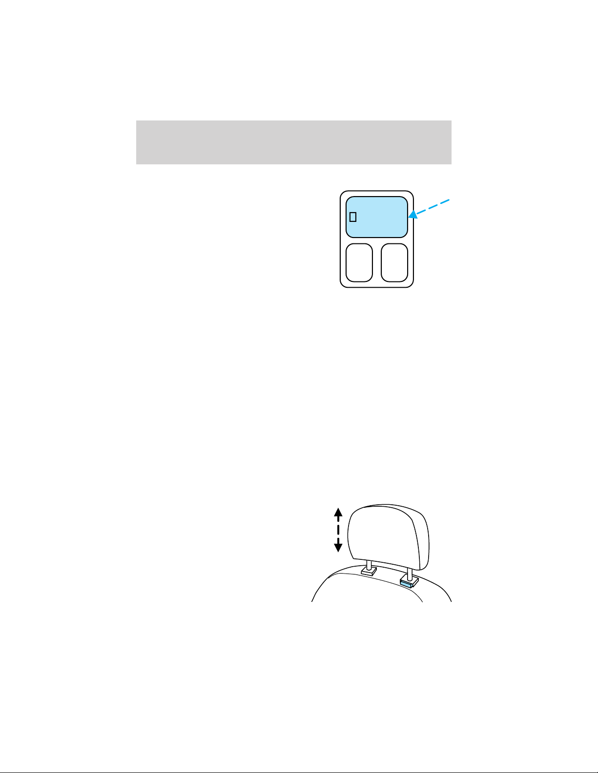
Seating and Safety Restraints
Memory seats/rearview mirrors/adjustable pedals (if equipped)
This system allows automatic
positioning of the driver seat,
outside rearview mirrors, and
adjustable pedals to two
programmable positions.
The memory seat control is located
on the instrument panel to the right
of the steering wheel.
• To program position one, move
the driver seat to the desired
position using the seat controls. Press the SET control. The SET
control indicator light will briefly illuminate. While the light is
illuminated, press control 1.
• To program position two, repeat the previous procedure using control
2.
A position can only be recalled when the transmission gearshift is in
Park. A memory seat position may be programmed at any time.
The memory seat positions are also recalled when you press your remote
entry transmitter UNLOCK control.
To program the memory seat to remote entry transmitter, refer to
Remote entry system in the Locks and security chapter.
SET
12
REAR SEATS
Head restraints
Lift the head restraint so that it is located directly or as close as possible
behind your head.
The head restraints can be moved
up and down.
92
Page 93

Seating and Safety Restraints
Push control to lower head restraint.
Seat mounted cup holders (if equipped)
Your vehicle may be equipped with cupholders mounted on the outboard
sides of the second row seat(s). The cupholder is designed to detach
from the seat when subjected to a heavy load. The cupholder can be
reinstalled by lining up the arms with the side shield holes and pushing
toward the seat.
93
Page 94

Seating and Safety Restraints
Adjusting rear seats
Lift control to move seat forward or backward.
• 2nd row bucket seat
• 2nd / 3rd row bench seat or 2nd
row bucket console seat
Pull control up to adjust seatback
position.
94
Page 95
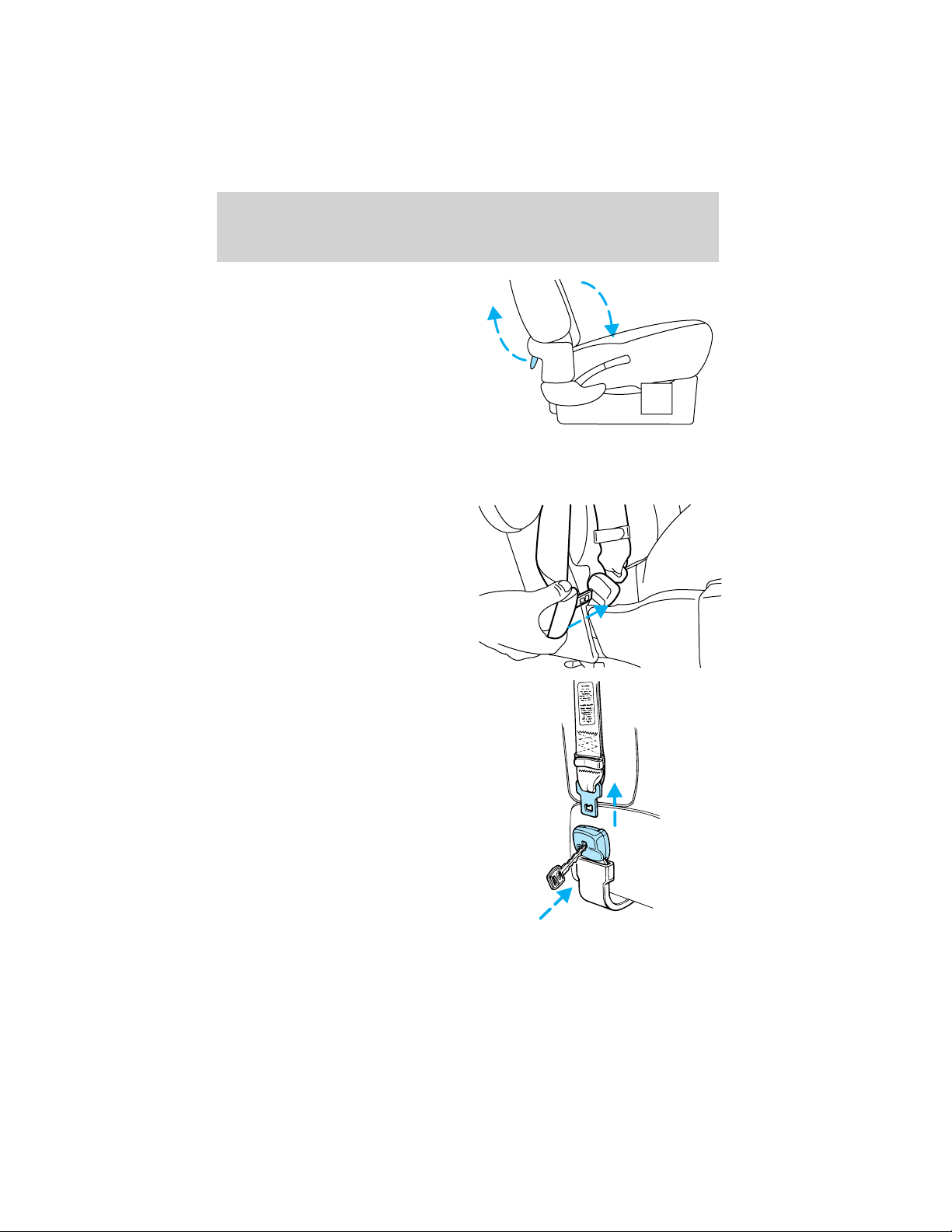
Seating and Safety Restraints
Pull control up to flip seatback to
forward flat position.
Bench seat or Bucket Console seat
To remove the seats:
1. (For 2nd row bench seat only.)
Disengage the lap/shoulder belt from
the side of the seat belt detach
anchors (if equipped) by inserting
the seatbelt tongue or a key into the
slot in the detachable anchor and
lifting upward.
95
Page 96

Seating and Safety Restraints
2. (For 2nd row bench seat only.) Using the clip attached to the end of
the shoulder belt(s), clip the end of the belt to the stationary portion of
the shoulder belt coming out of the trim panel. The end of the shoulder
belt must be clipped in order to keep it from striking anything during
vehicle operation.
If your bench seat is equipped with the forward fold down seatback,
position the seatback in the full down position to make removing the
seat easier.
3. From behind the seat, pull straight back on the release controls
located on each side of the seat, releasing the rear floor latches.
4. Lift up the back of the seat by the release controls to clear the floor
latches and then pull the seat rearward until the front hooks have come
out of the floor tubs.
5. Remove the seat.
96
Page 97

Seating and Safety Restraints
To install the seat:
1. Remove (if necessary) tub covers from the floor to expose the seat
mounts.
• To remove the tub cover(s), use a
screwdriver to pry the tub cover
(where indicated) upward and
out of the floor tub.
• To install the tub cover(s), first
insert the tabs located on the
opposite side of the pry location
into the slots of the floor tub then
press down on the other side of
the cover until it snaps into place
securely. (Additional tub covers
can be purchased as an accessory
from your dealer.)
2. Position the seat in the vehicle.
The 3rd row bench seat can be
placed in the 2nd row position.
3. Align seat front hooks to front tub pins, lower back of seat into the
rear tubs until both release controls latch into place. Be sure that the
seat is locked in place both front and back.
4. Make sure the safety belt is not twisted, then insert the seat belt
tongue into detachable anchor (if equipped) until you hear a “click” and
feel the latch engage.
97
Page 98

Seating and Safety Restraints
Always latch the vehicle seat to the floor, whether the seat is
occupied or empty. If not latched, the seat may cause injury
during a sudden stop.
Bucket seats
To remove the seat(s):
Position the seatback in the full down position to make removing the
seat easier.
1. From behind the seat, pull
straight back on the release controls
located on each side of the seat,
releasing the rear floor latches.
2. Lift up the back of the seat by the release controls to clear the floor
latches and then pull the seat rearward until the front hooks have come
out of the floor tubs.
3. Remove the seat.
4. Repeat steps 1 –3 for other bucket seat.
To install the seat(s):
Before installing the bucket seats, be sure that the seats are on the
correct side of the vehicle. They cannot be interchanged from one side
to the other. Each seat base has a bracket on the outboard side that
extends into a depression on the floor to ensure proper seat location.
Always be sure that the seat is positioned so that the seat belt buckle is
near the center aisle of the vehicle.
1. Position the seat in the vehicle.
2. Align seat front hooks to front tub pins, lower back of seat into the
rear tubs until both release controls latch into place. Be sure that the
seat is locked in place both front and back.
98
Page 99

Seating and Safety Restraints
Always latch the vehicle seat to the floor, whether the seat is
occupied or empty. If not latched, the seat may cause injury
during a sudden stop.
SAFETY RESTRAINTS
Personal Safety System
The Personal Safety System provides an improved overall level of frontal
crash protection to front seat occupants and is designed to help further
reduce the risk of air bag-related injuries. The system is able to analyze
different occupant conditions and crash severity before activating the
appropriate safety devices to help better protect a range of occupants in
a variety of frontal crash situations.
Your vehicle’s Personal Safety System consists of:
• Driver and passenger dual-stage air bag supplemental restraints.
• Front safety belts with pretensioners, energy management retractors,
and safety belt usage sensors.
• Driver’s seat position sensor.
• Passenger occupant classification sensor
• Front crash severity sensor.
• Restraints Control Module (RCM) with impact and safing sensors.
• Restraint system warning light and back-up tone.
• The electrical wiring for the air bags, crash sensor(s), safety belt
pretensioners, front safety belt usage sensors, driver seat position
sensor, passenger occupant classification sensor, and indicator lights.
How does the personal safety system work?
The Personal safety system can adapt the deployment strategy of your
vehicle’s safety devices according to crash severity and occupant
conditions. A collection of crash and occupant sensors provides
information to the Restraints control module (RCM). During a crash, the
RCM activates the safety belt pretensioners and/or either one or both
stages of the dual-stage air bag supplemental restraints based on crash
severity and occupant conditions.
The fact that the pretensioners or air bags did not activate for both front
seat occupants in a collision does not mean that something is wrong with
the system. Rather, it means the Personal safety system determined the
99
Page 100

Seating and Safety Restraints
accident conditions (crash severity, belt usage, etc.) were not
appropriate to activate these safety devices. Front air bags and
pretensioners are designed to activate only in frontal and near-frontal
collisions, not rollovers, side-impacts, or rear-impacts unless the collision
causes sufficient longitudinal deceleration.
Driver and passenger dual-stage air bag supplemental restraints
The dual-stage air bags offer the capability to tailor the level of air bag
inflation energy. A lower, less forceful energy level is provided for more
common, moderate-severity impacts. A higher energy level is used for
the most severe impacts. Refer to Air bag supplemental restraints
section in this chapter.
Front crash severity sensor
The front crash severity sensor enhances the ability to detect the
severity of an impact. Positioned up front, it provides valuable
information early in the crash event on the severity of the impact. This
allows your Personal safety system to distinguish between different levels
of crash severity and modify the deployment strategy of the dual-stage
air bags and safety belt pretensioners.
Driver’s seat position sensor
The driver’s seat position sensor allows your Personal safety system to
tailor the deployment level of the driver dual-stage air bag based on seat
position. The system is designed to help protect smaller drivers sitting
close to the driver air bag by providing a lower air bag output level.
Passenger occupant classification sensor (OCS)
For air bags to do their job they must inflate with great force, and this
force can pose a potentially deadly risk to occupants that are very close
to the air bag when it begins to inflate. For some occupants, this occurs
because they are initially sitting very close to the air bag. For other
occupants, this occurs when the occupant is not properly restrained by
seat belts or child safety seats and they move forward during pre-crash
braking. The most effective way to reduce the risk of unnecessary
injuries is to make sure all occupants are properly restrained. Accident
statistics suggest that children are much safer when properly restrained
in the rear seating positions than in the front.
Air bags can kill or injure a child in a child seat. NEVER place a
rear-facing child seat in front of an active air bag. If you must
use a forward-facing child seat in the front seat, move the seat all the
way back.
100
 Loading...