

Ford Taurus 2002, Sable 2002, 2002 Sable Workshop Manual

SECTION 307-01B: A utomatic Transaxle/Tra nsmission — 4F50N 2002 Taurus/Sable Wo rkshop Manual
10
2002 Taurus/Sable Workshop Manual
12/26/2010
http://www.fordtechservice.dealerconnection.com/pubs/content/~WS2H/~MUS~LEN/20/
...
REMOVAL
Procedure revision date: 06/20/2001
Transaxle — 3.0L 4V
Special Tool(s)
Remover, Halfshaft
205-241 (T86P-3514-A) or equivalent
Lifting Bracket, Engine (3.0L 4V -V6)
134-00243 or equivalent
Support, Bar Engine
303-290A
Adapters for 303-290A
303-290A-01
Adapter for 303-290A (Support Leg)
303-290A-03A
Slide Hammer
100-001 (T50T-100-A)
Removal
1. Remove the battery. For additional information, refer to Section 414-01.
2. Disconnect the mass air flow (M AF) sensor.
3. Disconnect the breather tubes .
4. Remove the engine air cleaner.
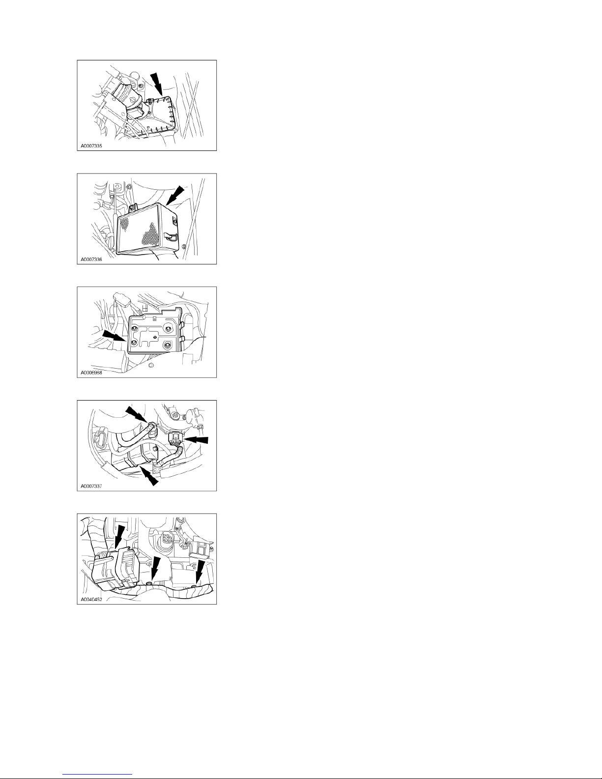
5. Remove the air filter assembly.
10
2002 Taurus/Sable Workshop Manual
12/26/2010
http://www.fordtechservice.dealerconnection.com/pubs/content/~WS2H/~MUS~LEN/20/
...
6. Remove the battery tray.
7. Disconnect the connectors.
8. Remove the electrical connector and the wiring harness from the bracket.
9. Remove the manual control lever cable.
1. Remove the nut.
2. Remove the shift actuator cable fitting from the shift cable and bracket.

10
2002 Taurus/Sable Workshop Manual
12/26/2010
http://www.fordtechservice.dealerconnection.com/pubs/content/~WS2H/~MUS~LEN/20/
...
10. Disconnect the power steering sensor connector.
11. Disconnect the power steering harness and output shaft sp eed (OSS) sensor connector.
12. Disconnect the wiring harness from the shift cable bracket.
13. Disconnect the turbine shaf t speed (TSS) sensor.
14. Remove the bolt from the coolant pipe bracket.
 Loading...