

Page 1
FORD RANGER Owner's Manual
Page 2

The information contained in this publication was correct at the time of going to print. In the interest of
continuous development, we reserve the right to change specifications, design or equipment at any time
without notice or obligation. No part of this publication may be reproduced, transmitted, stored in a
retrieval system or translated into any language in any form by any means without our written permission.
Errors and omissions excepted.
© Ford Motor Company 2012
All rights reserved.
Part Number: AB39120609AA (CG3575en) 06/2012 20120927145049
Page 3

Introduction
About This Manual...........................................7
Symbols Glossary.............................................7
Replacement Parts
Recommendation........................................8
At a Glance
At a Glance..........................................................9
Child Safety
Child Seats.........................................................16
Child Seat Positioning....................................17
ISOFIX Anchor Points...................................20
Booster Seats...................................................21
Child Safety Locks..........................................22
Occupant protection
Principle of Operation...................................23
Fastening the seat belts..............................25
Seat belt height adjustment......................25
Seat belt reminder.........................................26
Using seat belts during pregnancy..........26
Disabling the passenger airbag................26
Keys and Remote Controls
General Information on Radio
Frequencies..................................................28
Programming the remote control............28
Changing the remote control
battery............................................................29
Locks
Locking and Unlocking.................................30
Global Opening and Closing......................33
Engine immobiliser
Principle of Operation..................................34
Coded keys.......................................................34
Arming the engine immobiliser................34
Disarming the engine immobiliser...........34
Alarm
Principle of Operation..................................35
Arming the alarm...........................................36
Disarming the alarm.....................................36
Steering Wheel
Adjusting the Steering Wheel....................37
Audio Control...................................................37
Voice Control...................................................38
Wipers and Washers
Windscreen Wipers.......................................39
Autowipers.......................................................39
Windscreen Washers...................................40
Checking the Wiper Blades........................40
Changing the Wiper Blades.......................40
Lighting
Lighting Control..............................................42
Autolamps........................................................43
Front Fog Lamps............................................43
Rear Fog Lamps.............................................44
Headlamp Levelling......................................45
Hazard Warning Flashers............................45
Direction Indicators.......................................46
Interior Lamps.................................................46
Changing a Bulb.............................................46
Bulb Specification Chart.............................53
Windows and Mirrors
Power Windows..............................................54
Exterior Mirrors................................................56
Electric exterior mirrors................................56
Sliding Windows.............................................57
Instrument Cluster
Gauges...............................................................58
Warning Lamps and Indicators................58
Audible Warnings and Indicators.............62
1
Table of Contents
Page 4

Information Displays
General Information.....................................64
Trip Computer.................................................64
Personalised Settings...................................67
Climate Control
Principle of Operation..................................68
Air Vents............................................................68
Manual Climate Control..............................68
Automatic Climate Control..........................71
Heated Windows and Mirrors....................73
Seats
Sitting in the Correct Position....................74
Front Seats.......................................................74
Head Restraints..............................................78
Rear Seats.........................................................78
Heated Seats...................................................79
Convenience features
Clock....................................................................81
Instrument Lighting Dimmer......................81
Cigar Lighter......................................................81
Ashtray................................................................81
Auxiliary Power Points.................................82
Cup Holders......................................................82
Glasses Holder................................................83
Storage compartments...............................83
Auxiliary Input Socket..................................84
USB Port............................................................84
Cool Box............................................................84
Floor Mats.........................................................85
Starting and Stopping the
Engine
General Information.....................................86
Ignition Switch................................................86
Steering Wheel Lock....................................86
Starting a Petrol Engine..............................86
Starting a Diesel Engine...............................87
Diesel Particulate Filter................................87
Switching Off the Engine............................88
Fuel and Refuelling
Safety Precautions........................................89
Fuel Quality - Petrol......................................89
Fuel Quality - Diesel.....................................89
Catalytic Converter.......................................89
Fuel filler flap..................................................90
Refuelling..........................................................92
Fuel Consumption.........................................92
Technical Specifications.............................92
Transmission
Manual Transmission...................................94
Four-Wheel Drive...........................................94
Electronic Locking Differential..................95
Automatic Transmission.............................96
Brakes
Principle of Operation..................................99
Hints on Driving With Anti-Lock
Brakes............................................................99
Parking Brake..................................................99
Hill descent control (HDC)
Principle of Operation................................100
Using Hill Descent Control.......................100
Stability Control
Principle of Operation.................................102
Using Stability Control...............................102
Hill Start Assist
Principle of Operation................................104
Using hill start assist...................................104
2
Table of Contents
Page 5

Parking Aids
Principle of Operation................................106
Parking Aid - Vehicles With: Rear Parking
Aid..................................................................106
Rear view camera
Principle of Operation................................109
Rear View Camera.......................................109
Cruise Control
Principle of Operation...................................111
Using Cruise Control......................................111
Load Carrying
General Information.....................................114
Tailgate..............................................................114
Load Retaining Fixtures...............................114
Roof Racks and Load Carriers...................117
Towing
Towing a Trailer..............................................119
Tow Ball.............................................................121
Driving Hints
General Driving Points.................................123
Running-In.......................................................123
Cold Weather Precautions........................123
Reduced Engine Performance.................123
Driving Through Water................................124
Roadside Emergencies
First Aid Kit......................................................125
Warning Triangle...........................................125
Fuses
Fuse Box Locations......................................127
Changing a Fuse...........................................128
Fuse Specification Chart...........................129
Vehicle recovery
Towing Points.................................................137
Towing the Vehicle on Four Wheels.......137
Maintenance
General Information....................................138
Opening and Closing the Bonnet...........138
Under Bonnet Overview - 2.5L
Duratec-HE (122kW/165PS) -
MI4.................................................................140
Under Bonnet Overview - 2.2L
Duratorq-TDCi (Puma) Diesel............142
Under Bonnet Overview - 3.2L
Duratorq-TDCi (Puma) Diesel............144
Engine Oil Dipstick - 2.5L Duratec-HE
(122kW/165PS) - MI4.............................146
Engine Oil Dipstick - 2.2L Duratorq-TDCi
(Puma) Diesel/3.2L Duratorq-TDCi
(Puma) Diesel...........................................146
Engine Oil Check...........................................146
Engine Coolant Check.................................147
Power Steering Fluid Check.....................148
Brake and Clutch Fluid Check.................148
Draining the Fuel Filter Water Trap........148
Washer Fluid Check.....................................149
Technical Specifications...........................149
Vehicle Care
Cleaning the Exterior...................................153
Cleaning the Interior....................................154
Repairing Minor Paint Damage...............154
Vehicle battery
Jump-Starting the Vehicle........................155
Battery connection points........................156
Battery warning symbols..........................156
Wheels and Tyres
General Information.....................................157
Changing a Road Wheel.............................157
Tyre Care..........................................................163
3
Table of Contents
Page 6

Using Winter Tyres.......................................163
Using Snow Chains......................................163
Technical Specifications...........................164
Vehicle identification
Vehicle Identification Plate.......................165
Vehicle Identification Number.................165
Capacities and Specific-
ations
Technical Specifications...........................166
Navigation introduction
General Information....................................174
Road Safety....................................................174
Navigation Quick start
Navigation Quick start................................176
Navigation unit overview
Navigation unit overview............................177
Loading the navigation data.....................179
System settings
System settings............................................180
Navigation system
Route options menu....................................183
Route displays...............................................184
Traffic Message Channel
Principle of Operation.................................185
Using TMC.......................................................185
Map updates
Map updates..................................................186
Audio introduction
Important audio information...................187
Audio unit overview
Audio unit overview.....................................188
Audio System Security
Security code.................................................195
Audio Unit Clock and Date
Displays
Setting the clock on the audio unit.......196
Audio unit operation
On/off control................................................198
Sound button.................................................198
Waveband button........................................198
Station tuning control................................198
Station preset buttons...............................199
Autostore control.........................................199
Traffic information control.......................199
Audio unit menus
Automatic volume control........................201
Digital signal processing (DSP)..............201
News broadcasts..........................................201
Alternative frequencies..............................201
Regional mode (REG)...............................202
Compact Disc Player
Compact disc playback............................203
Track selection.............................................203
Fast forward/reverse..................................203
Shuffle/random...........................................203
Repeat compact disc tracks...................203
Compact disc track scanning.................204
MP3 file playback........................................204
MP3 display options..................................206
Ending compact disc playback..............207
4
Table of Contents
Page 7

Auxiliary input (AUX IN)
socket
Auxiliary input (AUX IN) socket.............208
Audio system care
Antenna..........................................................209
Audio Troubleshooting
Audio troubleshooting................................210
Telephone
General Information.....................................211
Telephone setup............................................211
Bluetooth setup.............................................212
Telephone controls......................................213
Using the telephone....................................213
Voice control
Principle of Operation.................................216
Using voice control.......................................216
Audio unit commands.................................217
Telephone commands...............................225
Climate control commands....................230
Connectivity
General Information....................................232
Connecting an external device...............233
Connecting an external device - Vehicles
With: Bluetooth........................................233
Using a USB device.....................................234
Using an iPod................................................236
Appendices
Type approvals.............................................238
Type approvals.............................................238
Type approvals.............................................238
Electromagnetic compatibility...............238
5
Table of Contents
Page 8

6
Page 9
ABOUT THIS MANUAL
Thank you for choosing Ford. We
recommend that you take some time to
get to know your vehicle by reading this
manual. The more that you know about it,
the greater the safety and pleasure you
will get from driving it.
WARNING
Always drive with due care and
attention when using and operating
the controls and features on your
vehicle.
Note: This manual describes product
features and options available throughout
the range, sometimes even before they are
generally available. It may describe options
not fitted to your vehicle.
Note: Some of the illustrations in this
manual may be used for different models,
so may appear different to your vehicle.
However, the essential information in the
illustrations is always correct.
Note: Always use and operate your vehicle
in line with all applicable laws and
regulations.
Note: Pass on this manual when selling
your vehicle. It is an integral part of the
vehicle.
This vehicle has received the endorsement
of TÜV, the accredited international testing
organisation, for its allergy-friendly
properties.
All materials used in the manufacture of
the interior of this vehicle meet strict
requirements of the TÜV TOXPROOF
Criteria Catalogue for Vehicle Interiors by
TÜV Produkt and Umwelt GmbH and are
designed to minimize the risk of allergic
reactions.
Additionally an efficient pollen filter
protects the passengers against allergen
particles in the outdoor air.
For more information, contact TÜV at
www.tuv.com.
SYMBOLS GLOSSARY
Symbols in this handbook
WARNING
You risk death or serious injury to
yourself and others if you do not
follow the instructions highlighted
by the warning symbol.
CAUTION
You risk damaging your vehicle if you
do not follow the instructions
highlighted by the caution symbol.
Symbols on your vehicle
When you see these symbols, read and
follow the relevant instructions in this
handbook before touching or attempting
adjustment of any kind.
7
Introduction
Page 10

REPLACEMENT PARTS RECOMMENDATION
Genuine Ford parts and accessories have
been designed specifically for your vehicle.
Unless we have specifically stated, we
have not tested non-Ford parts and
accessories and, therefore, we will not
guarantee that they are suitable for your
vehicle. We recommend that you ask your
Ford Dealer for advice on parts and
accessories suitable for your vehicle.
8
Introduction
Page 11
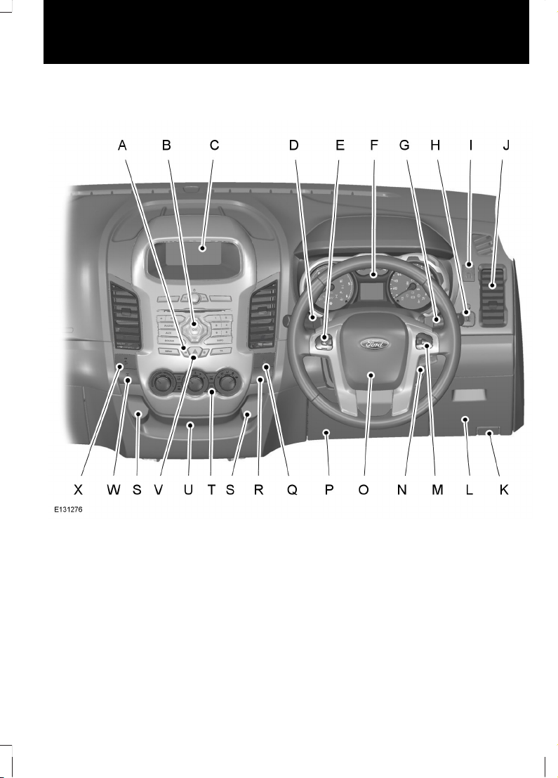
Instrument panel overview - Right-hand drive
9
At a Glance
Page 12
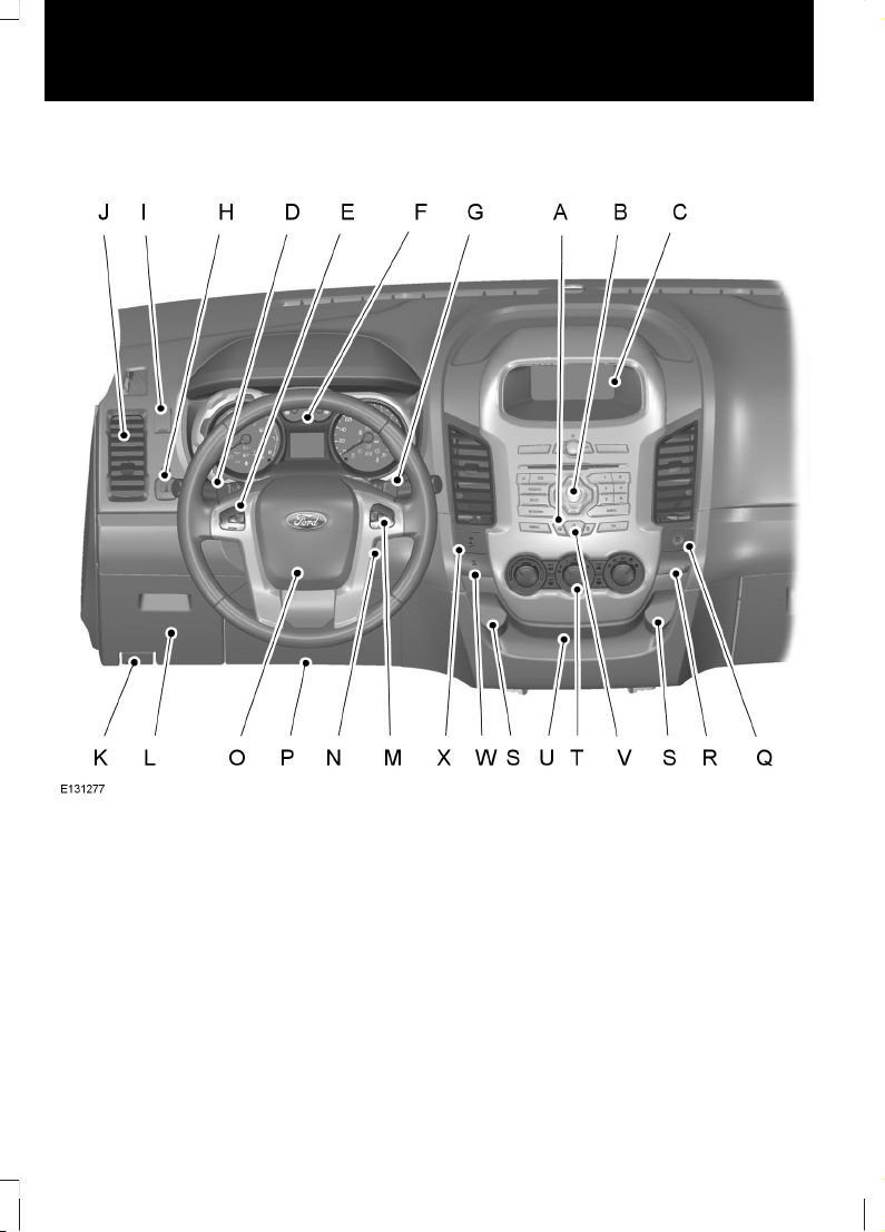
Instrument panel overview - Left-hand drive
Door lock button. See Locking
and Unlocking (page 30).
A
Audio unit. See Audio unit
overview (page 188).
B
Multi-functional display.C
Multi-function lever: Direction
indicators. See Direction
Indicators (page 46). Main
Beam. See Lighting Control
(page 42). or Wiper lever. See
Wipers and Washers (page
39).
D
Audio control. See Audio
Control (page 37).
E
10
At a Glance
Page 13
Instrument cluster. See Gauges
(page 58). See Warning L amps
and Indicators (page 58).
F
Multi-function lever: Direction
indicators. See Direction
Indicators (page 46). Main
Beam. See Lighting Control
(page 42). or Wiper lever. See
Wipers and Washers (page
39).
G
Exterior mirror control. See
Electric exterior mirrors (page
56).
H
Headlamp levelling switch. See
Headlamp Levelling (page 45).
I
Air vents. See Air Vents (page
68).
J
Bonnet release lever. See
Opening and Closing the
Bonnet (page 138).
K
Driver side storage
compartment. See Ashtray
(page 81).
L
Cruise control. See Cruise
Control (page 111).
M
Ignition switch. See Ignition
Switch (page 86).
N
Horn.O
Driver knee airbag. See Principle
of Operation (page 23).
P
Stability control (ESP) switch.
See Using Stability Control
(page 102).
Q
Passenger airbag deactivation
warning lamp. See Disabling
the passenger airbag (page
26).
R
Auxiliary power sockets. See
Auxiliary Power Points (page
82).
S
Climate controls. See Manual
Climate Control (page 68).
T
Auxiliary input and USB. See
Auxiliary Input Socket (page
84). See USB Port (page 84).
U
Hazard warning flasher switch.
See Hazard Warning Flashers
(page 45).
V
Electronic Locking Differential
(ELD) button. See Four-Wheel
Drive (page 94).
W
Hill descent control. See Hill
descent control (HDC) (page
100).
X
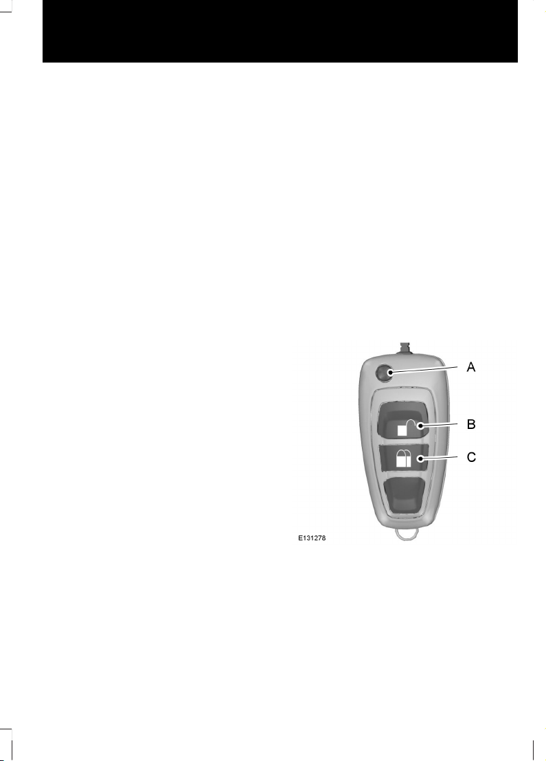
Locking and unlocking
Unlocking the vehicle
Key fold/unfold buttonA
UnlockB
LockC
Press the unlock button once to unlock the
vehicle.
Press the lock button once to activate
central locking.
11
At a Glance
Page 14
Press the lock button twice within three
seconds to double lock the doors.
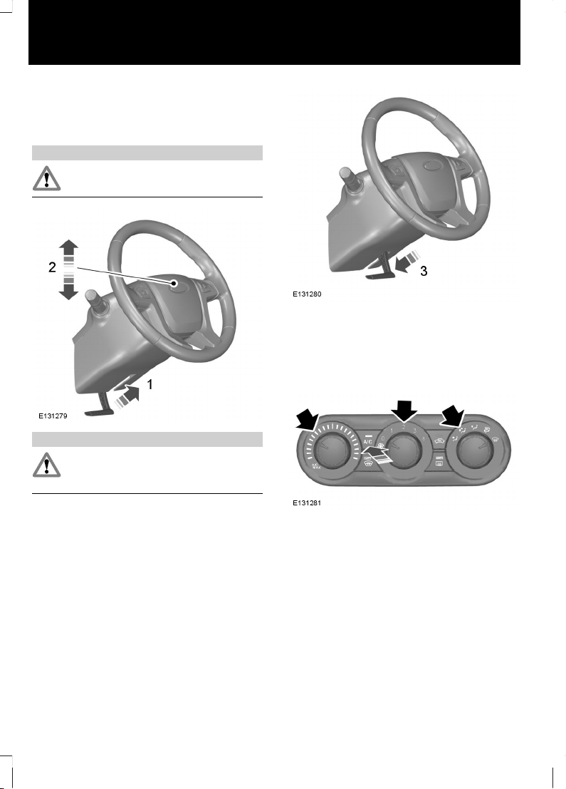
Adjusting the steering wheel
WARNING
Never adjust the steering wheel
when the vehicle is moving.
WARNING
Make sure that you fully engage the
locking lever when returning it to its
original position.
See Adjusting the Steering Wheel (page
37).
Manual climate control
Recommended settings for cooling
Select the outside air.
Open the centre and side air vents.
Direct the centre air vents upwards and the
side air vents toward the side windows.
12
At a Glance
Page 15
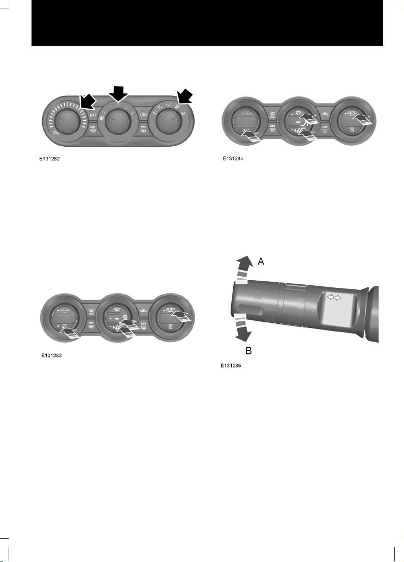
Recommended settings for heating
Select the outside air.
Close the centre air vents and open the
side air vents.
Direct the side air vents toward the side
windows.
See Manual Climate Control (page 68).
Automatic climate control
Recommended settings for cooling
Select the outside air.
Set the temperature to 22°C (72°F).
Open the centre and side air vents.
Direct the centre air vents upwards and the
side air vents toward the side windows.
Recommended settings for heating
Select the outside air.
Set the temperature to 22°C (72°F).
Open the centre and side air vents.
Direct the centre air vents upwards and the
side air vents toward the side windows.
Direction indicators
If the lever is tapped up or down, the
direction indicators will flash three time.
See Direction Indicators (page 46).
13
At a Glance
Page 16
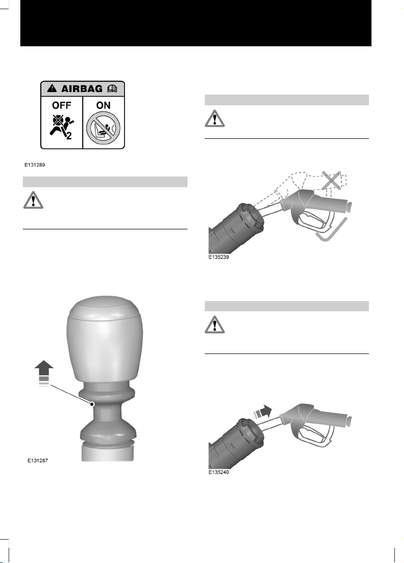
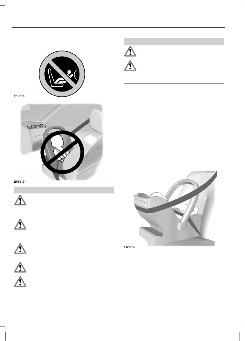
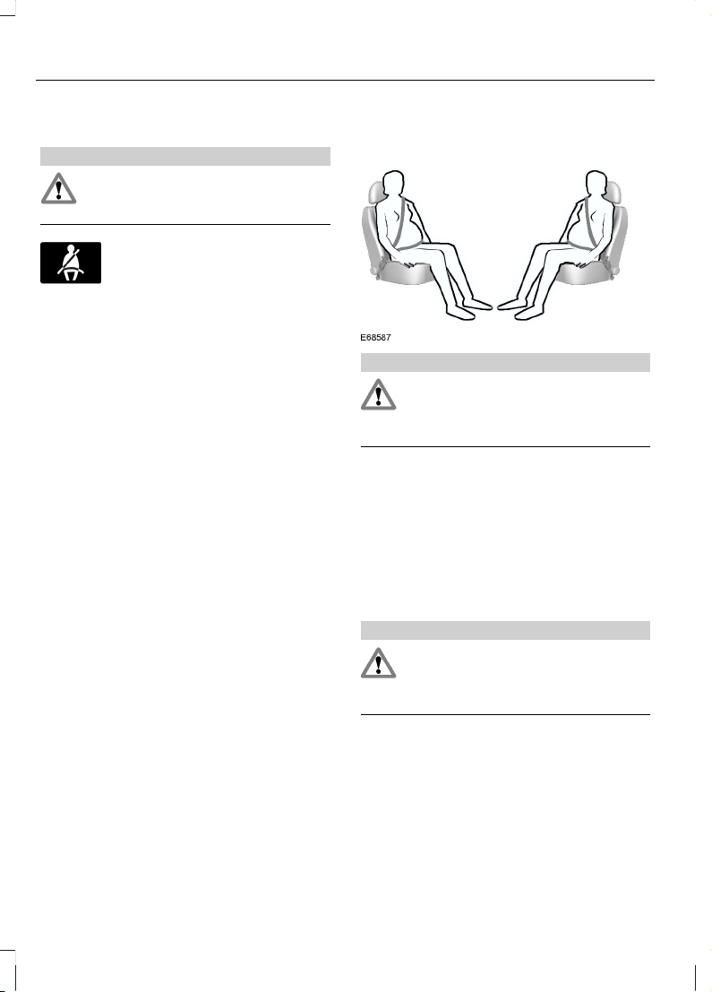
Airbag
WARNING
To avoid the risk of death or serious
injury, never use a rearward facing
child restraint in the front, unless the
air bag is OFF.
See Child Seat Positioning (page 17).
Manual transmission
Selecting reverse gear - 6 speed
It is necessary to raise the collar whilst
selecting reverse gear in 6-speed vehicles.
See Manual Transmission (page 94).
Refuelling
WARNING
Take care when refuelling to avoid
spilling any residual fuel from the fuel
pipe nozzle.
Insert the fuel pipe nozzle up to the first
notch on the nozzle, and keep it in position
on the fuel filler opening.
WARNING
We recommend that you wait at
least 10 seconds before removing the
fuel nozzle to allow any residual fuel
to drain into the fuel tank.
Slightly raise the fuel nozzle to remove it.
14
At a Glance
Page 17

See Fuel filler flap (page 90).
15
At a Glance
Page 18
CHILD SEATS
WARNINGS
Secure children that are less than
150 centimetres (59 inches) tall in a
suitable, approved child restraint, in
the rear seat.
Extreme Hazard! Do not use a
rearward facing child restraint on a
seat protected by an air bag in front
of it!
Read and follow the manufacturer’s
instructions when you are fitting a
child restraint.
Do not modify child restraints in any
way.
Do not hold a child on your lap when
the vehicle is moving.
WARNINGS
Do not leave unattended children in
your vehicle.
If your vehicle has been involved in
an accident, have the child restraints
checked by properly trained
technicians.
Note: Mandatory use of child restraints
varies from country to country.
Only child restraints certified to
ECE-R44.03 (or later) have been tested
and approved for use in your vehicle. A
choice of these are available from your
Dealer.
Child restraints for different mass
groups
Use the correct child restraint as follows:
Baby safety seat
Secure children that weigh less than 13
kilograms (29 pounds) in a rearward facing
baby safety seat (Group 0+) in the rear
seat.
16
Child Safety
Page 19
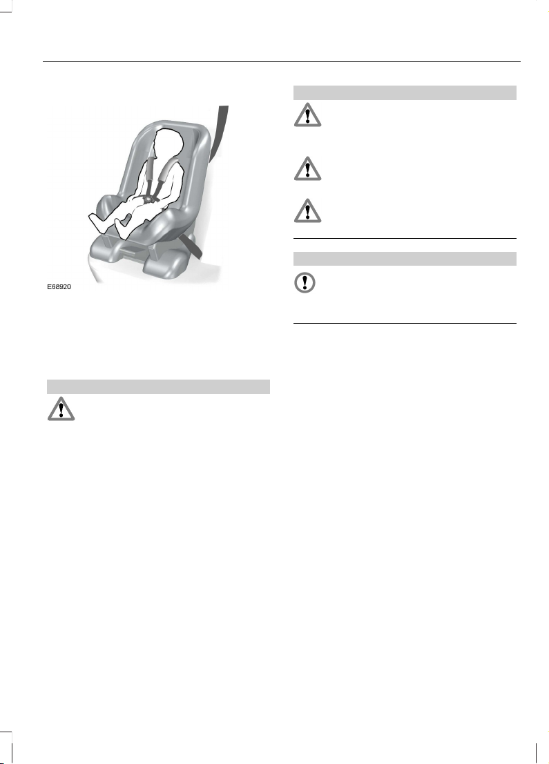
Child safety seat
Secure children that weigh between 13 and
18 kilograms (29 and 40 pounds) in a child
safety seat (Group 1) in the rear seat.
CHILD SEAT POSITIONING
WARNINGS
Please consult your Dealer for the
latest details relating to Ford
recommended child seats.
WARNINGS
Extreme Hazard! Do not use a
rearward facing child restraint on a
seat protected by an air bag in front
of it!
When using a child seat with a
support leg, the support leg must
rest securely on the floor.
When using a child seat with a seat
belt, make sure that the seat belt is
not slack or twisted.
CAUTION
The child seat must rest tightly
against the vehicle seat. It may be
necessary to lift or remove the head
restraint. See Head Restraints (page 78).
Note: When using a child seat on a front
seat, always adjust the front passenger seat
to its fully rearwards position. If it proves
difficult to tighten the lap section of the seat
belt without slack remaining, adjust the
seatback to the fully upright position and
raise the height of the seat. See Seats
(page 74).
17
Child Safety
Page 20

Mass group categories
Seating positions 3210+0
22 - 36 kg15 - 25 kg9 - 18 kgUp to 13 kgUp to 10 kg
UF¹UF¹UF¹XX
Front outboard
passenger seat with
airbag ON
U¹U¹U¹U¹U¹
Front outboard
passenger seat with
airbag OFF
UUUUURear seats
XXXXXSingle cab center seat
X Not suitable for children in this mass group.
U Suitable for universal category child seats approved for use in this mass group.
U¹ Suitable for universal category child seats approved for use in this mass group. However,
we recommend that you secure children in a government approved child seat, in the rear
seat.
UF¹ Suitable for universal category forward facing child seats approved for use in this
mass group. However, we recommend that you secure children in a government approved
child seat, in the rear seat.
ISOFIX child seats - Double cab
Mass group categories
Seating positions
10+
Forward facingRear facing
9 - 18 kgUp to 13 kg
Not ISOFIX equipped
Size classFront seat
Seat type
A, B, B1, C, D
*
E, D, C
*
Size class
Rear outboard seat ISOFIX
IL, IUF
***
IL
**
Seat type
18
Child Safety
Page 21

Mass group categories
Seating positions
10+
Forward facingRear facing
9 - 18 kgUp to 13 kg
Not ISOFIX equipped
Size classRear centre seat
Seat type
IL Suitable for particular ISOFIX child restraints systems of the semi-universal category.
Please consult child restraints systems suppliers' vehicle recommendation lists.
IUF Suitable for ISOFIX forward facing child restraints systems of universal category
approved for use in this mass group and ISOFIX size class.
*
The ISOFIX size class for both universal and semi-universal child restraints systems
is defined by the capital letters A to G. These identification letters are displayed on ISOFIX
child restraints.
**
At time of publishing the recommended Group O+ ISOFIX baby safety seat is the Britax
Roemer Baby Safe. Please consult your Dealer for the latest details relating to Ford
recommended child seats.
***
At time of publishing the recommended Group 1 ISOFIX child seat is the Britax Roemer
Safefix PLUS. Please consult your Dealer for the latest details relating to Ford
recommended child seats.
19
Child Safety
Page 22
ISOFIX ANCHOR POINTS
WARNING
Use an anti-rotation device when
using the ISOFIX system. We
recommend that you use a top tether
or a support leg.
Note: When you are purchasing an ISOFIX
restraint, make sure that you know the
correct mass group and ISOFIX size class
for the intended seating locations. See
Child Seat Positioning (page 17).
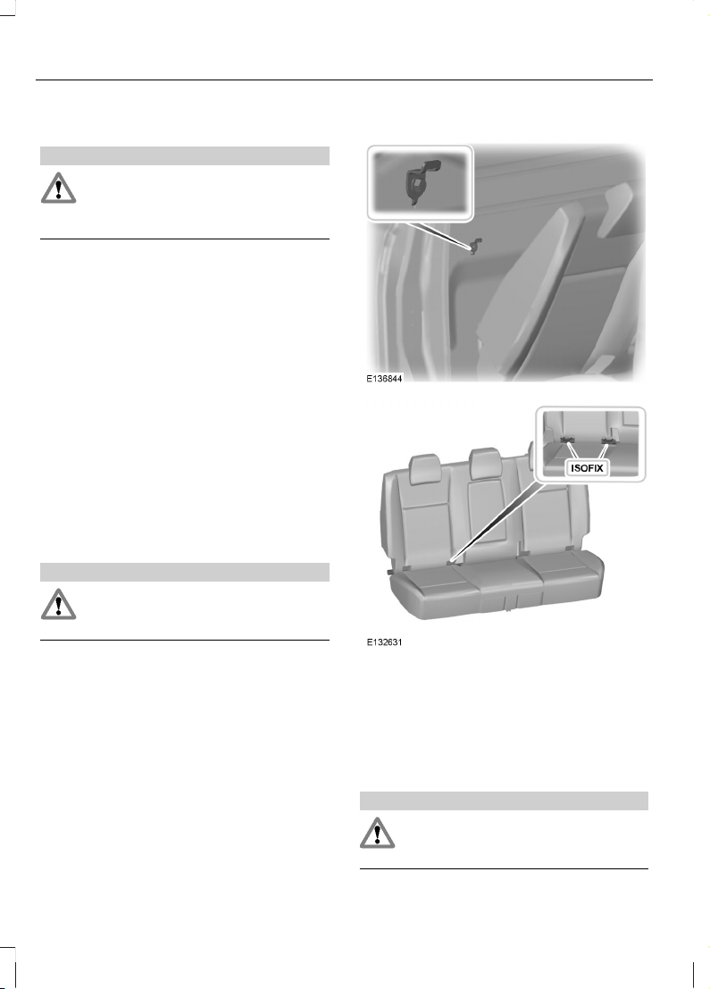
Your vehicle is fitted with ISOFIX anchor
points that accommodate universally
approved ISOFIX child restraints.
The ISOFIX system comprises two rigid
attachment arms on the child restraint that
attach to anchor points on the 2nd row
seats, where the cushion and backrest
meet. Tether anchor points are fitted to
the back panel trim for child restraints with
a top tether.
Attaching a child restraint with a
top tether
WARNING
Do not attach a tether strap to
anything other than the correct
tether anchor point.
Double cab
1. Remove the head restraint. See Head
Restraints (page 78).
2. Place the child seat on the back seat
cushion and fold the relevant seatback
forward. See Rear Seats (page 78).
3. Route the tether strap to the anchor
point.
WARNING
Make sure the top tether strap is not
slack or twisted and is properly
located on the anchor point.
20
Child Safety
Page 23
4. Push the seatback to the upright
position.
WARNINGS
Make sure that the seatback is
secure and fully engaged in the
catch.
Make sure the safety seat is fitted
correctly. There is a risk of injury.
5. Push the child seat back firmly to
engage the ISOFIX lower anchor points.
6. Tighten the tether strap in line with the
child seat manufacturers instructions.
We recommend that you use a tether strap
where fitted.
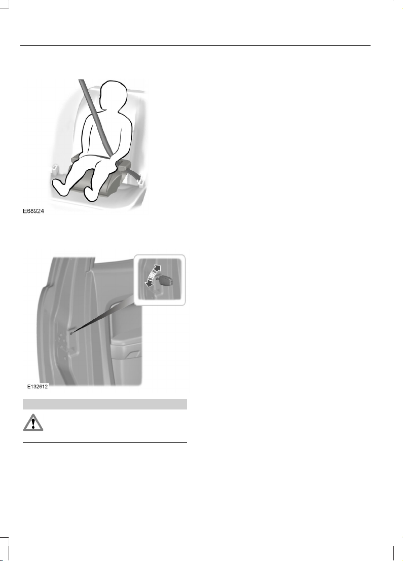
BOOSTER SEATS
WARNINGS
Do not install a booster seat or a
booster cushion with only the lap
strap of the seat belt.
Do not install a booster seat or a
booster cushion with a seat belt that
is slack or twisted.
Do not put the seat belt under your
child’s arm or behind its back.
Do not use pillows, books or towels
to boost your child’s height.
Make sure that your children sit in an
upright position.
Secure children that weigh more
than 15 kilograms (33 pounds) but
are less than 150 centimetres (59
inches) tall in a booster seat or a booster
cushion.
CAUTION
When using a child seat on a rear seat,
make sure that the child seat rests
tightly against the vehicle seat. It may
be necessary to lift or remove the head
restraint. See Head Restraints (page 78).
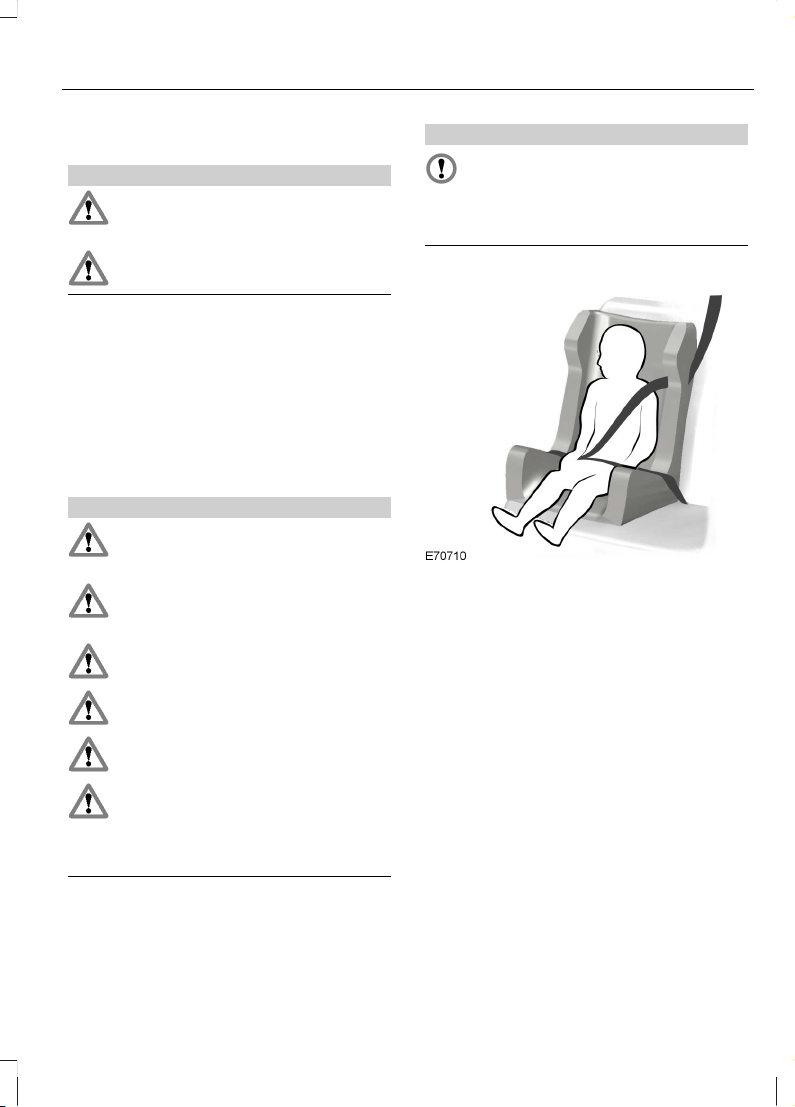
Booster seat (Group 2)
We recommend that you use a booster
seat that combines a cushion with a
backrest instead of a booster cushion only.
The raised seating position will allow you
to position the shoulder strap of the adult
seat belt over the centre of your child’s
shoulder and the lap strap tightly across
its hips.
21
Child Safety
Page 24
Booster cushion (Group 3)
CHILD SAFETY LOCKS
WARNING
You cannot open the doors from
inside if you have put the child safety
locks on.
Left-hand side
Turn anti-clockwise to lock and clockwise
to unlock.
Right-hand side
Turn clockwise to lock and anti-clockwise
to unlock.
22
Child Safety
Page 25
PRINCIPLE OF OPERATION
Airbags
WARNINGS
Do not modify the front of your
vehicle in any way. This could
adversely affect deployment of the
airbags.
Original text according to ECE
R94.01: Extreme Hazard! Do not use
a rearward facing child restraint on
a seat protected by an airbag in front of it!
Wear a seat belt and keep sufficient
distance between yourself and the
steering wheel. Only when you use
the seat belt properly, can it hold you in a
position that allows the airbag to achieve
its optimum effect. See Sitting in the
Correct Position (page 74).
Have repairs to the steering wheel,
steering column, seats, airbags and
seat belts carried out by a properly
trained technician.
Keep the areas in front of the airbags
free from obstruction. Do not affix
anything to or over the airbag covers.
Do not poke sharp objects into areas
where airbags are fitted. This could
damage and adversely affect
deployment of the airbags.
Use seat covers designed for seats
with side airbags. Have these fitted
by a properly trained technician.
Note: You will hear a loud bang and see a
cloud of harmless powdery residue if an
airbag deploys. This is normal.
Note: Only wipe airbag covers with a damp
cloth.
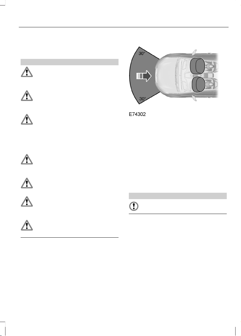
Driver and front passenger airbags
The driver and front passenger airbags will
deploy during significant frontal collisions
or collisions that are up to 30 degrees from
the left or the right. The airbags will inflate
within a few thousandths of a second and
deflate on contact with the occupants,
thus cushioning forward body movement.
During minor frontal collisions, overturns,
rear collisions and side collisions, the driver
and front passenger airbags will not
deploy.
Driver knee airbag
CAUTION
Do not attempt to open the driver
knee airbag cover.
The driver knee airbag will deploy during
frontal collisions or collisions that are up
to 30 degrees from the left or the right. The
airbag will inflate within a few thousandths
of a second and deflate on contact with
the occupants, thus providing a cushion
between the driver’s knees and the steering
column. During overturns, rear collisions
and side collisions, the knee airbag will not
deploy.
For item location: See At a Glance (page
9).
23
Occupant protection
Page 26
Note: The knee airbag has a lower
deployment threshold than the front
airbags. During a minor collision, it is
possible that only the knee airbag deploys.
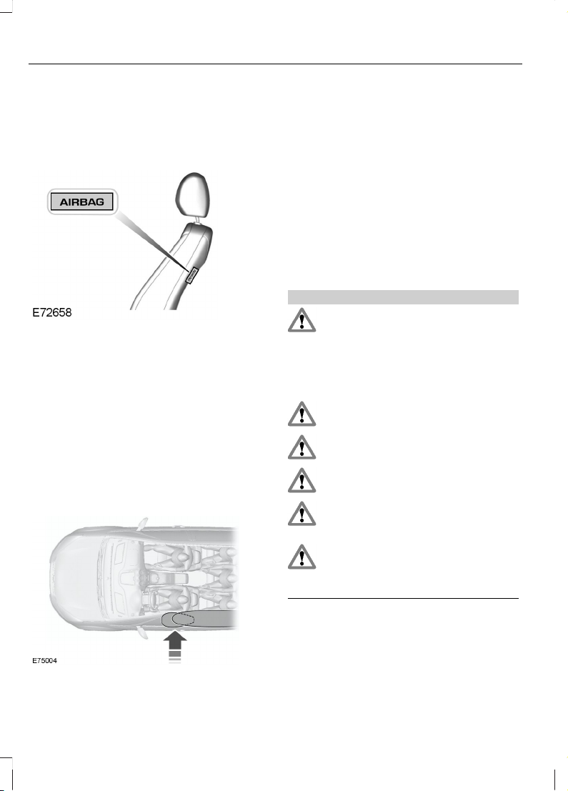
Side airbags
Side airbags are fitted inside the seatback
of the front seats. A label indicates that
side airbags are fitted to your vehicle.
The side airbags will deploy during
significant lateral collisions. The airbags
will inflate within a few thousandths of a
second and deflate on contact with the
occupants, thus providing protection for
the chest and shoulder areas. During minor
lateral collisions, overturns, front collisions
and rear collisions, the side airbags will not
deploy.
Curtain airbags
Curtain airbags are fitted inside the trim
panels over the front and rear side
windows. Moulded badges in the B-pillar
trim panels indicate that curtain airbags
are fitted to your vehicle.
The curtain airbags will deploy during
significant lateral collisions. The airbag will
inflate within a few thousandths of a
second and deflate on contact with the
occupants, thus providing protection for
the head. During minor lateral collisions,
front collisions, rear collisions, or overturns
the curtain airbags will not deploy.
Seat belts
WARNINGS
Wear a seat belt and keep sufficient
distance between yourself and the
steering wheel. Only when you use
the seat belt properly, can it hold you in a
position to achieve its optimum effect. See
Sitting in the Correct Position (page
74).
Never use a seat belt for more than
one person.
Use the correct buckle for each seat
belt.
Do not use a seat belt that is slack
or twisted.
Do not wear thick clothing. The seat
belt must fit tightly around your body
to achieve its optimum effect.
Position the shoulder strap of the
seat belt over the centre of your
shoulder and position the lap strap
tightly across your hips.
24
Occupant protection
Page 27
The driver and front passenger seat belt
retractors are fitted with a seat belt
pretensioner. Seat belt pretensioners have
a lower deployment threshold than the
airbags. During minor collisions, it is
possible that only the seat belt
pretensioners will deploy.
Status after a collision
WARNING
Seat belts subjected to strain, as a
result of an accident, should be
renewed and the anchorages
checked by a properly trained technician.
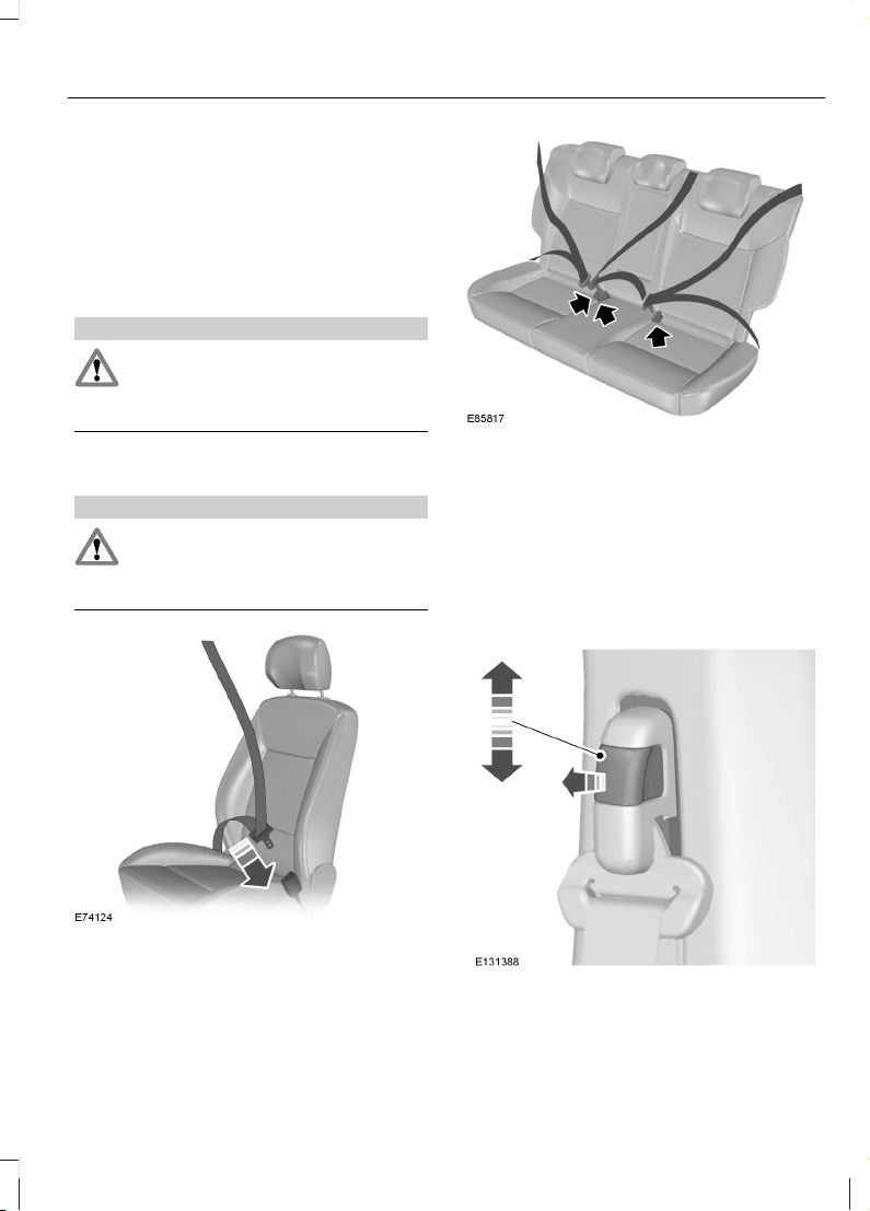
FASTENING THE SEAT BELTS
WARNING
Insert the tongue into the buckle until
you hear a distinct click. You have
not fastened the seat belt properly
if you do not hear a click.
Pull the belt out steadily. It may lock if you
pull it sharply or if the vehicle is on a slope.
Press the red button on the buckle to
release the belt. Let it retract completely
and smoothly.
SEAT BELT HEIGHT ADJUSTMENT
To raise or lower, pull the locking button
on the adjuster and move as necessary.
25
Occupant protection
Page 28
SEAT BELT REMINDER
WARNING
The occupant protection system will
only provide optimum protection
when you use the seat belt properly.
Type 1: The seat belt warning lamp will be
illuminated for 6 seconds when the ignition
is turned on to remind the driver to fasten
the seatbelt.
Type 2: The seat belt warning lamp will
be illuminated at any time when the drivers
seat belt is not fastened.
Type 3: The seat belt reminder warning
lamp illuminates and an audible warning
will sound if the driver or front passenger
seat belt has not been fastened and the
vehicle exceeds a relatively low speed. It
will also illuminate if either of the seat belt
is unfastened when the vehicle is moving.
The audible warning will go off after five
minutes but the seat belt reminder warning
lamp will remain on until the seat belt is
fastened.
Deactivating the seat belt
reminder
See your dealer.
USING SEAT BELTS DURING PREGNANCY
WARNING
Position the seat belt correctly for
your safety and that of your unborn
child. Do not use only the lap strap
or the shoulder strap.
Position the lap strap comfortably across
your hips and low beneath your pregnant
abdomen. Position the shoulder strap
between your breasts, above and to the
side of your pregnant abdomen.
DISABLING THE PASSENGER AIRBAG
WARNING
Make sure that the passenger airbag
is disabled when using a rearward
facing child restraint on the front
passenger seat.
26
Occupant protection
Page 29
Fitting the passenger airbag
deactivation switch
WARNING
If you need to fit a child restraint on
a seat protected by an operational
airbag in front of it, have a passenger
airbag deactivation switch fitted. Ask your
dealer for further information.
Note: The key switch is located in the glove
compartment with an airbag deactivation
lamp in the instrument panel.
If the airbag warning lamp illuminates or
flashes when you are driving, this indicates
a malfunction. Remove the child restraint
and have the system checked immediately.
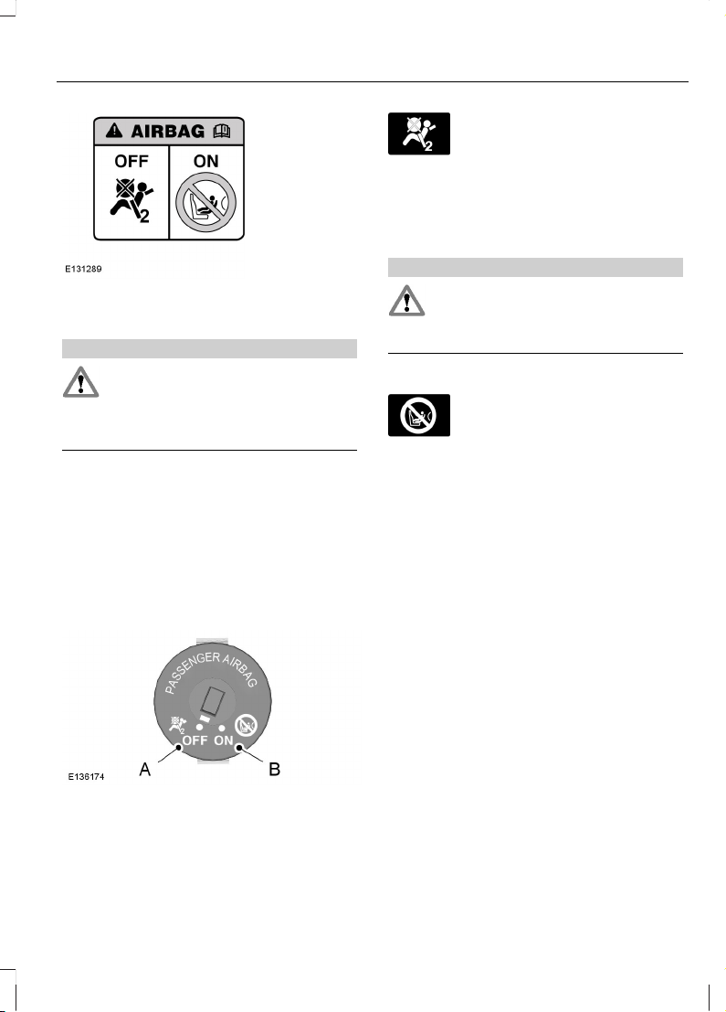
Disabling the passenger airbag
DisabledA
EnabledB
Turn the switch to position A.
When you switch the ignition on,
the passenger airbag OFF
warning lamp illuminates
indicating that the passenger airbag is
disabled. For item location: See At a
Glance (page 9).
Enabling the passenger airbag
WARNING
Make sure that the passenger airbag
is enabled when you are not using a
child restraint on the front passenger
seat.
Turn the switch to position B.
When you switch the ignition on,
the passenger airbag ON
warning lamp illuminates
indicating that the passenger airbag is
enabled. For item location: See At a
Glance (page 9).
27
Occupant protection
Page 30
GENERAL INFORMATION ON RADIO FREQUENCIES
CAUTIONS
The radio frequency used by your
remote control can also be used by
other short distance radio
transmissions (e.g. amateur radios,
medical equipment, wireless headphones,
remote controls and alarm systems). If the
frequencies are jammed, you will not be
able to use your remote control. You can
lock and unlock the doors with the key.
Check your vehicle is locked before
leaving it unattended. This will
safeguard against any potential
malicious frequency blocking.
Note: You could unlock the doors if you
press the buttons on the remote control
unintentionally.
The operating range between your remote
control and your vehicle varies depending
on the environment.
PROGRAMMING THE REMOTE CONTROL
Note: Additional remote controls can be
programmed only if the vehicle is supplied
with atleast one remote control.
A maximum of eight remote controls
(including the one supplied with your
vehicle) can be programmed. The remote
controls must remain inside the vehicle
during the programming procedure. Fasten
the front seat belts and close all doors to
ensure that conflicting chimes do not
sound during programming.
Programming a new remote
control
1. To programme new remote controls
turn the ignition key to position II four
times within six seconds.
2. Turn the ignition to position 0. A tone
sounds to indicate that it is now
possible to programme the remote
controls for ten seconds.
3. Press any button on a new remote
control. A tone will sound as
confirmation.
4. Repeat this last step for all your remote
controls, including your original. Do not
remove the key from the ignition when
pressing the button on this remote
control.
5. Switch the ignition back on (position
II) or wait for ten seconds without
programming another remote control
to end the key programming. Only the
remote controls which you have just
programmed are now able to lock and
unlock the vehicle.
Reprogramming the unlocking
function
Note: When you press the unlock button
either all the doors are unlocked or only the
driver’s door is unlocked. Pressing the unlock
button again unlocks all the doors.
Press and hold the unlock and lock buttons
on the remote key simultaneously for at
least four seconds with the ignition off. The
direction indicators will flash twice to
confirm the change.
To return to the original unlocking function,
repeat the process.
Programming the additional key
Note: The additional keys can be
programmed only if you already have two
programmed keys.
28
Keys and Remote Controls
Page 31

1. Insert the first key and switch on the
ignition.
2. Remove the key within 10 seconds.
3. Insert the second key within 10 seconds
and switch on the ignition.
4. Remove the key within 10 seconds.
5. Insert the additional key within 10
seconds which need to be
programmed.
CHANGING THE REMOTE CONTROL BATTERY
Make sure that you dispose of
old batteries in an
environmentally friendly way.
Seek advice from your local authority
regarding recycling.
1. Insert a screwdriver in the position shown
and gently push the clip.
2. Press the clip down to release the
battery cover.
3. Carefully remove the cover.
4. Turn the remote control over to remove
the battery.
5. Install a new battery (3V CR 2032) with
the + facing upwards.
6. Replace the battery cover.
29
Keys and Remote Controls
Page 32

LOCKING AND UNLOCKING
Note: Do not leave your keys in the vehicle.
Note: All the doors will lock automatically
when the vehicle is driven at or above 7
Km/h (4.3 mph). This function can be
enabled or disabled, see driver
configuration mode later in this procedure.
Locking and unlocking the doors
with the key
UnlockA
LockB
Note: To double lock the doors, turn the
key to the lock position twice within three
seconds.
Locking and unlocking the doors
with the remote control
Automatic relocking: The doors will
relock automatically if you do not open a
door within 45 seconds of unlocking the
doors with the remote control. The door
locks and the alarm will return to their
previous state.
Note: This option can be switched off by
your Ford dealer.
Key fold/unfold buttonA
UnlockB
LockC
Press the button B once to unlock the
vehicle.
Press the button C once to activate central
locking.
Note: Central locking is activated only when
all the passenger doors are closed.
Press the button C twice within four
seconds to double lock the doors.
Note: Double locking is activated only when
all the passenger doors are closed and the
bonnet is closed in the vehicle fitted with
alarm.
30
Locks
Page 33

WARNING
Do not activate double locking when
persons or animals are inside the
vehicle. You will not be able to
unlock the doors from inside if you have
double locked them.
Note: If the ignition is switched on with the
double locking function activated, the lock
will automatically return to single lock stage.
Double locking is a theft protection feature
that prevents someone from opening the
doors from the inside.
Note: The driver’s door can be unlocked
with the key. This needs to be used if the
remote control is not functioning.
Note: If the vehicle remains locked for
several weeks, the remote control will be
disabled. The vehicle must be unlocked and
the engine started using the key. Unlocking
and starting the vehicle once will enable the
remote control.
Reprogramming the unlocking function
The unlocking function may be
reprogrammed so that only the driver’s
door is unlocked. See Programming the
remote control (page 28).
Locking and unlocking confirmation
Note: When you lock the doors, the
direction indicators will flash once.
When you double lock the doors, the
direction indicators will flash twice.
When you unlock the doors the direction
indicators will flash one long flash.
Child play protection function
If the remote control buttons are pressed
continuously several times, the locking and
unlocking function will be blocked for a
while to avoid door latches from
overheating.
Locking and unlocking the doors
from inside
Press the button. For item
location. See At a Glance (page
9).
UnlockA
OpenB
Driver configuration mode
Note: This operation has to be done within
30 seconds.
1. Switch the ignition ON.
2. Press door lock button three times.
3. Switch the ignition OFF.
4. Press door lock button three times.
5. Switch the ignition ON.
The system will chirp to indicate that the
driver configuration mode is enabled.
Once in driver configuration mode, follow
the steps mentioned below to toggle the
status of the automatic locking by speed
or automatic unlocking.
31
Locks
Page 34

Automatic locking by speed
Press the central lock or unlock button
twice within three seconds and wait for
three seconds to toggle the automatic
locking by speed function. The system will
chirp when toggling.
Automatic unlocking
Note: Automatic unlock is default enabled.
Press the central lock or unlock button
three time within three seconds and wait
for three seconds to toggle the automatic
unlocking function.
If the automatic unlocking function is
enabled:
• All doors will be unlocked while
opening the driver door or front
passenger door (vehicles not delivered
with remote control) from inside, with
the key in ignition.
If the automatic unlocking function is
disabled:
• Only the respective door will be
unlocked while opening from inside.
Note: Opening the rear doors will never
unlock the other doors, when opened from
inside.
Locking the doors individually with
the key
Note: If the central locking function fails to
operate, the doors can be individually locked
using the key in the position shown.
Left-hand side
Turn clockwise to lock.
Right-hand side
Turn anti-clockwise to lock.
Unlocking
Note: If the child safety locks have also
been activated, pulling the internal lever will
only deactivate the emergency locking and
not the child safety lock. The doors can only
be opened using the external door handle.
Note: If the doors have been unlocked, they
have to be locked individually using this
method until the central locking function
has been repaired.
Unlock the driver's door using the key. The
other doors can be unlocked individually by
pulling the interior door handles on those
doors.
32
Locks
Page 35

GLOBAL OPENING AND CLOSING
Note: You can operate the windows for up
to one minute after you switch off the
ignition. They will be deactivated as soon
as a door is opened.
Note: Global closing will only operate if you
have set the memory correctly for each
window. See Power Windows (page 54).
Global opening
To open all the windows, press and hold
the remote control unlock button for at
least three seconds. Press any remote
control button again to stop the opening
function.
Global closing
WARNING
Take care when using global closing.
In an emergency, press a button
immediately to stop the windows.
To close all the windows, press and hold
the remote control lock button for at least
two seconds. Press any remote control
button again to stop the closing function.
The anti-trap function is also active during
global closing.
33
Locks
Page 36

PRINCIPLE OF OPERATION
The engine immobiliser is a theft protection
system that prevents someone from
starting the engine with an incorrectly
coded key.
CODED KEYS
Note: Do not shield your keys with metal
objects. This may prevent the receiver from
recognising your key as a valid one.
Note: Have all of your remaining keys
erased and recoded if you lose a key. Ask
your dealer for further information. Have
replacement keys recoded together with
your existing keys.
If you lose a key, you can obtain a
replacement from your Ford Dealer. If
possible, provide them with the key
number from the tag provided with the
original keys. You can also obtain
additional keys from your Ford Dealer.
ARMING THE ENGINE IMMOBILISER
The engine immobiliser is armed
automatically a short time after you have
switched the ignition off.
The indicator in the instrument cluster will
flash to confirm that the system is
operating.
DISARMING THE ENGINE IMMOBILISER
The engine immobiliser is disarmed
automatically when you switch the ignition
on with a correctly coded key.
The indicator in the instrument cluster will
come on for approximately three seconds
and then go out. If the indicator stays on
for one minute or flashes for approximately
one minute and then repeatedly at irregular
intervals, your key has not been recognised.
Remove the key and try again.
If you are unable to start the engine with a
correctly coded key, this indicates a
malfunction. Have the immobiliser checked
immediately.
34
Engine immobiliser
Page 37

PRINCIPLE OF OPERATION
Alarm system
Your vehicle may be equipped with one of
the following alarm systems:
• Perimeter alarm with interior sensors.
• Perimeter alarm with interior sensors
and battery back-up sounder.
Interior sensors
The interior sensors are activated when
you arm the alarm. See Arming the alarm
(page 36).
WARNINGS
The sensors in the interior lamp unit
must not be covered up. Do not
activate the alarm if any persons,
animals or other moving objects are inside
the vehicle.
The interior sensors may not detect
movement with in the cab correctly
if the rear seat base in the double
cab is left in the upright position.
Do not leave the glasses holder open.
Note: This may result in false alarms if
animals or moving objects are inside the
vehicle.
Note: False alarms can also be triggered
by the fuel fired heater. If you are using the
fuel fired heater, direct the air flow towards
the footwell.
The sensors act as a deterrent against
unauthorised intrusion by sensing any
movement within the vehicle.
Alarm Horn
The alarm horn will sound a siren when the
alarm is triggered. It is armed when you
lock the vehicle. This will not sound if
someone disconnects the vehicle battery
or the alarm horn itself.
Battery back-up sounder
The battery back-up sounder is an extra
alarm system which will sound a siren
when the alarm is triggered. It is armed
when you lock the vehicle. The sounder
has its own battery and will sound an
alarm siren even if someone disconnects
the vehicle battery or the battery back-up
sounder itself.
Triggering the alarm
Once armed, the alarm is triggered in any
of the following ways:
• If someone opens a door or the bonnet
without a valid key or remote control.
• If someone removes the multi function
display.
• If the ignition is turned to position I, II
or III without a valid key.
• If the interior sensors detect movement
within the vehicle.
• On vehicles with a battery back-up
sounder, if someone disconnects the
vehicle battery or the battery back-up
sounder itself.
If the alarm is triggered, the alarm horn will
sound for 30 seconds and the hazard
warning flasher will flash for five minutes.
Any further attempts to perform one of the
above will trigger the alarm again.
35
Alarm
Page 38

ARMING THE ALARM
To arm the alarm, lock the vehicle. See
Locks (page 30).
DISARMING THE ALARM
Disarm and silence the alarm by unlocking
the doors with the key and inserting the
key into the ignition switch with a correctly
coded key within 12 seconds, or unlocking
the doors with the remote control.
36
Alarm
Page 39

ADJUSTING THE STEERING WHEEL
WARNING
Never adjust the steering wheel
when the vehicle is moving.
Note: Make sure that you are sitting in the
correct position. See Sitting in the Correct
Position (page 74).
WARNING
Make sure that you fully engage the
locking lever when returning it to its
original position.
AUDIO CONTROL
Volume upA
Seek upB
Volume downC
Seek downD
ModeE
Mode
Press and hold the mode button to select
the audio source.
Press the mode button to:
• tune the radio to the next preset
station
• accept an incoming telephone call
• end a telephone call.
Seek
Press the seek button to:
• tune the radio to the next station up or
down the frequency band
• play the next or the previous CD track.
37
Steering Wheel
Page 40

Press and hold the seek button to:
• tune the radio up or down the
frequency band
• seek through a CD track.
VOICE CONTROL
Voice controlA
Press the voice control button
to select or deselect voice
control.
For further information: See Voice control
(page 216).
38
Steering Wheel
Page 41

WINDSCREEN WIPERS
CAUTION
Operating this function with the
engine off will drain the battery.
Single wipeA
Intermittent wipe or autowipersB
Normal wipeC
High speed wipeD
Intermittent wipe
Long wipe intervalA
Intermittent wipeB
Short wipe intervalC
AUTOWIPERS
CAUTIONS
Do not switch autowipers on in dry
weather conditions. The rain sensor
is very sensitive and the wipers may
operate if dirt, mist or flies hit the
windscreen.
Replace the wiper blades as soon as
they begin to leave bands of water
and smears. If you do not replace
them, the rain sensor will continue to
detect water on the windscreen and the
wipers will operate, even though the
majority of the windscreen is dry.
Fully defrost the windscreen in icy
conditions before you switch
autowipers on.
Switch autowipers off before you
enter a car wash.
High sensitivityA
OnB
Low sensitivityC
If you switch autowipers on, the wipers will
not cycle until water is detected on the
windscreen. The rain sensor will then
continuously measure the amount of water
on the windscreen and adjust the speed
of the wipers automatically.
39
Wipers and Washers
Page 42

Adjust the sensitivity of the rain sensor
using the rotary control. With low
sensitivity, the wipers will operate when
the sensor detects a lot of water on the
windscreen. With high sensitivity, the
wipers will operate if the sensor detects a
small amount of water on the windscreen.
WINDSCREEN WASHERS
CAUTION
Operating this function with the
engine off will drain the battery.
WARNING
Do not operate the windscreen
washers for more than 10 seconds
or when the reservoir is empty.
CHECKING THE WIPER BLADES
Run the tip of your fingers over the edge of
the blade to check for roughness.
Clean the wiper blade lips with water
applied with a soft sponge.
CHANGING THE WIPER BLADES
Windscreen wiper blades
CAUTIONS
Set the windscreen wipers in the
service position to change the wiper
blades.
You can use the service position in
winter to provide easier access to the
wiper blades for freeing them from
snow and ice. The windscreen wipers will
return to their normal position as soon as
you switch on the ignition so make sure
that the outside of the windscreen is free
from snow and ice before you switch on
the ignition.
40
Wipers and Washers
Page 43

Service position
1. Turn the ignition key to position 0 from
position II.
2. Pull the washer lever towards the
steering wheel within three seconds.
Note: Make sure that the wiper blade locks
into place.
Install in the reverse order.
41
Wipers and Washers
Page 44

LIGHTING CONTROL
Lighting control positions
OffA
Auto-light controlB
HeadlampsC
Side and tail lampsD
Parking lamps
CAUTION
Prolonged use of the parking lamps
will discharge the battery.
Switch off the ignition.
Both sides
Set the lighting control to position D.
One side
Note: The parking lamp has to be switched
on within 10 minutes from the key out. If
exceeded, the key has to reinserted.
Right-hand sideA
Left-hand sideB
Main and dipped beam
Push the lever forward to switch between
main and dipped beam.
Headlamp flasher
Pull the lever towards the steering wheel.
Home safe lighting
Switch the ignition off and pull the
direction indicator lever towards the
steering wheel or if you have switched
autolamps on, turn the key from position
II to I or 0 to switch the headlamps on.
42
Lighting
Page 45

You will hear a short tone. The headlamps
will go off automatically after three
minutes with any door open, or 30 seconds
after the last door has been closed.
With all doors closed, but within the 30
second delay, opening any door will result
in the three minute timer starting again.
The home safe lights can be cancelled by
either pulling the direction indicator lever
towards the steering wheel again or by
turning the ignition switch on.
Approach lamps
The side repeaters, number plate lamp and
the puddle lamps will come on and stays
illuminated for 25 seconds when the
vehicle is unlocked with the remote control.
If a door is opened the light will stay on
until the door is closed, ignition is turned
on or for 10 minutes.
Emergency stop lights
Hazard warning flashers or fog lights will
come on when the brake is applied
suddenly at a speed above 50 km/h (30
mph).
AUTOLAMPS
WARNING
In severe weather conditions, it may
be necessary to switch your
headlamps on manually.
Note: If you have switched autolamps on,
you can only switch the main beam on when
autolamps has switched the headlamps on.
The headlamps will come on and go off
automatically depending on the ambient
light.
FRONT FOG LAMPS
Control lever
WARNING
Only use the front fog lamps when
visibility is considerably restricted by
fog, snow or rain.
Note: You cannot switch the front fog
lamps on unless you have switched the
headlamps on.
43
Lighting
Page 46

Adjustment
You can adjust the front fog lamp aiming
slightly for driving comfort.
Note: Fog lamp adjustment must meet the
local regulation requirements.
1. Position the unloaded vehicle on a flat,
level surface.
2. Seat one person in the driver’s seat.
3. Start the engine so that the battery
remains charged.
4. Turn the front fog lamp on.
5. Adjust the fog lamp aiming such that
the cut off line is not more than X: 20
m (65.6 ft).
REAR FOG LAMPS
WARNINGS
Only use the rear fog lamps when
visibility is restricted to less than 50
metres (164 feet).
Do not use the rear fog lamps when
it is raining or snowing and visibility
is more than 50 metres (164 feet).
Note: You cannot switch the rear fog lamps
on unless you have switched the headlamps
and front fog lamp on.
44
Lighting
Page 47

HEADLAMP LEVELLING
Without headlamp levellingA
With headlamp levellingB
You can adjust the level of the headlamp
beams according to the vehicle load.
Raised headlamp beamsA
Lowered headlamp beamsB
Set the headlamp levelling control to zero
when your vehicle is unloaded. Set it to
provide illumination between 35 and 100
metres (114 and 328 feet) when your
vehicle is partially or fully loaded.
HAZARD WARNING FLASHERS
For item location: See At a Glance (page
9).
45
Lighting
Page 48

DIRECTION INDICATORS
Right-hand sideA
Left-hand sideB
INTERIOR LAMPS
Courtesy lamp
OffA
Door contactB
OnC
If you set the switch to position B, the
courtesy lamp will come on when you
unlock or open a door. If you leave a door
open with the ignition switch off, the
courtesy lamp will go off automatically
after some time to prevent the vehicle
battery from discharging. To switch it back
on, switch on the ignition for a short time.
The courtesy lamp will also come on when
you switch off the ignition. It will go off
automatically after a short time or when
you start or restart the engine.
If you set the switch to position C with the
ignition switch off, the courtesy lamp will
come on. It will go off automatically after
a short time to prevent the vehicle battery
from discharging. To switch it back on,
switch on the ignition for a short time.
Reading lamps
If you switch off the ignition, the reading
lamps will go off automatically after some
time to prevent the vehicle battery from
discharging. To switch them back on,
switch on the ignition for a short time.
CHANGING A BULB
WARNINGS
Switch the lights and the ignition off.
Let the engine compartment and the
bulb cool down before removing it.
CAUTION
Only fit bulbs of the correct
specification. See Bulb
Specification Chart (page 53).
Note: The following instructions describe
how to remove the bulbs. Fit replacements
in the reverse order unless otherwise stated.
46
Lighting
Page 49

You may notice fogging or small water
droplets in the lamp units from time to
time. This does not affect the function of
the lamp, and will clear when the lamps
are turned on and the vehicle is driven.
Note: If in any doubt about any of the
following bulb replacement procedures,
please have the bulb replaced by your
Authorised Ford Dealer.
Headlamp main and dipped beam
CAUTIONS
Do not touch the glass of the bulb.
Ensure bulb is correctly seated before
replacing the spring clip. Checking the
bulb location through the front of the
headlamp lens can be a useful aid to
ensuring the bulb is correctly aligned.
1. Open the bonnet. See Opening and
Closing the Bonnet (page 138).
2. Disconnect the electrical connector by
pressing in the spring releases on both
sides of the connector.
3. Remove the rubber boot.
4. Release the bulb retaining spring clip
and remove the bulb.
5. Insert the replacement bulb and retain
it using the spring clip.
Note: Ensure that the rubber boot seals
correctly against the bulb and headlight
housing and that it is not out of shape while
installing.
Side lamps and front direction
indicators
Direction indicatorA
Side lampB
1. Remove the bulb holder from the
headlamp assembly.
2. Remove the bulb.
47
Lighting
Page 50

Front fog lamps
Note: You cannot separate the bulb from
the bulb holder.
1. Disconnect the electrical connector.
2. Turn the bulb holder anti-clockwise
and remove it.
Side repeaters
1. Slide the lens to the rear and remove
it.
2. Disconnect the electrical connector.
Exterior mirror lamps
Side repeater lampA
Puddle lampB
Note: These are not serviceable items,
please consult your dealer if they fail.
Rear lamps
Type 1
48
Lighting
Page 51

Tail and brake lampA
Direction indicatorB
Reversing lampC
Fog lamp (left-hand side for
LHD)
D
1. Open the tailgate.
2. Remove the screws.
3. Remove the rear lamp.
4. Turn the bulb holder anti-clockwise
and remove it.
5. Remove the bulb.
Type 2
Direction indicatorA
Tail and brake lampB
Reversing lampC
1. Remove the screws.
2. Remove the lens.
3. Remove the bulb.
Number plate lamp
Type 1
1. Slide the unit away from the connector
and remove it.
49
Lighting
Page 52

2. Remove the connector with bulb.
3. Remove the bulb.
Type 2
1. Remove the screws.
2. Remove the lens.
3. Remove the bulb.
Interior lamp
Stretch and double cab
1. Carefully prise out the lamp.
2. Turn the bulb holder anti-clockwise
and remove it.
3. Remove the bulb.
Front reading lamps
Without alarm sensor
1. Carefully prise out the lamp.
2. Turn the bulb holder anti-clockwise
and remove it.
3. Remove the bulb.
50
Lighting
Page 53

With alarm sensor
• Carefully prise out the lamp.
• For reading lamps, turn the bulb holder
anti-clockwise and remove it.
• Remove the bulb.
• For centre lamp, carefully prise out the
lamp lens.
• Remove the bulb.
Centre high mount stop lamp
Type 1
51
Lighting
Page 54

1. Remove the cover.
2. Remove the screws.
3. Carefully prise out the lamp.
4. Disconnect the electrical connector.
5. Remove the bulb holder by turning it
to 45 degree anticlockwise.
6. Remove the bulbs.
Type 2
1. Remove the cover.
2. Remove the screws.
3. Carefully prise out the lamp.
4. Disconnect the electrical connector.
5. Pull out the bulb holder.
6. Remove the bulbs.
52
Lighting
Page 55

BULB SPECIFICATION CHART
Power (watts)SpecificationBulb
55/60
H4Headlamp main and dipped
beam
21P21WFront direction indicator
5W5WSide lamp
55H11Front fog lamp
5-Side repeater*
21WY21WRear direction indicator
21/5W21/5WTail and brake lamp
21W21WReversing lamp
21W21WRear fog lamp
5W5WNumber plate lamp
5W5WInterior lamp
5W5WReading lamp
5W5WCentre high mount stop
lamp
5W5WRoof bar lamp
* Bulb replacement is not possible as the
bulb is an integral part of the unit. The side
repeater lamp unit has to be changed.
53
Lighting
Page 56

POWER WINDOWS
WARNING
Do not operate the electric windows
unless they are free from obstruction.
Note: If you operate the switches often
during a short period of time, the system
might become inoperable for a certain time
to prevent damage due to overheating.
Note: If you operate both the switch on the
relevant door and the switch for that
window on the driver’s door at the same
time, the window will stop moving.
Switch on the ignition to operate the
electric windows.
Driver’s door switches (Double
cab)
You can operate all the windows with the
switches on the door trim panel of the
driver’s door.
OpenA
CloseB
Driver’s door switches (Single and
Stretch cab)
OpenA
CloseB
Front and rear passengers’ door
switches
OpenA
CloseB
Opening and closing the windows
automatically
Press or lift the switch to the second action
point and release it. Press or lift it again to
stop the window.
54
Windows and Mirrors
Page 57

Safety switch for the rear windows
Note: You can always operate the rear
windows and front passenger window from
the driver’s door if global opening and
closing is fitted.
Note: Only vehicles with global opening
and closing will have a light on the switch
to indicate that it is active.
A switch in the driver’s door disables the
rear and front passenger electric window
switches.
The light in the safety switch comes on and
the lights in the rear window switches go
off when the rear windows are disabled.
Resetting the memory of the
electric windows
WARNING
The anti-trap function is deactivated
until you have reset the memory.
After the battery has been disconnected
from the vehicle you must reset the
memory separately for each window:
1. Lift the switch until the window is fully
closed. Hold the switch lifted for one
more second.
2. Release the switch and lift it again,
until a click is heard from the relay, for
one more second.
3. Open the window and try to close it
automatically.
4. Repeat the procedure if the window
does not close automatically.
Safety mode
WARNING
The anti-trap function is not active
during this procedure.
If the system detects a malfunction, it
enters a safety mode. The windows will
move for only about 0.5 seconds at a time
and then stop again. Close the windows
by pressing the switch again when the
windows stop moving. Have this checked
immediately.
Global opening and global closing
(GO/GC) (If fitted)
You can also operate the electric windows
for one minute with the ignition off via the
global opening and global closing function.
See Global Opening and Closing (page
33).
Note: Global opening and global closing
will open or close the windows
automatically only on vehicles equipped
with this feature.
Note: Global closing will only operate if you
have set the memory correctly for each
window. Memory is set by default, you have
to reset it only if there is a problem.
Anti-trap function (vehicles with
GO/GC only)
WARNING
Careless closing of the windows can
override the protection function and
cause injuries.
The electric windows will stop
automatically while closing (auto-up) and
reverse some distance if there is an
obstacle in the way.
55
Windows and Mirrors
Page 58

Overriding the anti-trap function
CAUTION
While you close the window (auto-up)
for the third time with the obstacle in
the way, the anti-trap function is
disabled. Make sure there are no obstacles
in the way of the closing window.
To override this protection function when
there is a resistance, for example, in the
winter, proceed as follows:
1. Close the window twice until it reaches
the resistance and let it reverse.
2. Close the window a third time to the
resistance. The anti-trap function is
disabled and you cannot close the
window automatically. The window
will override the resistance and you can
fully close it manually.
3. If the window does not close after the
third attempt, have it checked by a
properly trained technician.
EXTERIOR MIRRORS
WARNING
Do not overestimate the distance of
the objects that you see in the
convex mirror. Objects seen in
convex mirrors will appear smaller and
further away than they actually are.
Manual folding mirrors
Folding
Push the mirror towards the door window
glass.
Unfolding
Make sure that you fully engage the mirror
in its support when returning it to its
original position.
ELECTRIC EXTERIOR MIRRORS
WARNING
Do not overestimate the distance of
the objects that you see in the
convex mirror. Objects seen in
convex mirrors will appear smaller and
further away than they actually are.
Left-hand mirrorA
OffB
Right-hand mirrorC
56
Windows and Mirrors
Page 59

The electric exterior mirrors are fitted with
a heating element that will defrost or
demist the mirror glass. See Heated
Windows and Mirrors (page 73).
Electric folding mirrors
To fold and unfold the mirrors, briefly press
the switch. If the switch is pressed again
while the mirrors are moving, they will stop
and reverse the direction of movement.
SLIDING WINDOWS
57
Windows and Mirrors
Page 60

GAUGES
TachometerA
Fuel gaugeB
Engine coolant temperature
gauge
C
SpeedometerD
Illumination dimming buttonE
Information displayF
Trip computer display select and
reset button
G
Engine coolant temperature gauge
Shows the temperature of the engine
coolant. At normal operating temperature,
the needle will remain in the centre section.
CAUTION
Do not restart the engine until the
cause of overheating has been
resolved.
If the needle enters the red section, the
engine is overheating. Stop the engine,
switch the ignition off and determine the
cause once the engine has cooled down.
See Engine Coolant Check (page 147).
Fuel gauge
The arrow adjacent to the fuel pump
symbol tells you on which side of your
vehicle the fuel filler cap is located.
WARNING LAMPS AND INDICATORS
The following warning lamps and
indicators will come on briefly when you
switch the ignition on to confirm that the
system is operational:
• ABS warning lamp
• Vehicle immobiliser indicator
• Brake system warning lamp
• Ignition warning lamp
• Airbag warning lamp
• Low fuel level warning lamp
• Stability control (ESP) indicator
• Oil pressure warning lamp
• Oil Change Reminder Indicator (Diesel
only)
• Engine warning lamps
• Four-wheel drive indicator
• Four-wheel drive low (4L) indicator
• Electronic locking differential (ELD)
indicator
• Water-in-fuel indicator (Diesel only)
• Washer fluid level indicator
• DPF (Diesel Particulate Filter)
• Ice/Frost warning indicator
ABS warning lamp
If it illuminates when you are
driving, this indicates a
malfunction. You will continue
to have normal braking (without ABS).
Have the system checked by a properly
trained technician as soon as possible.
58
Instrument Cluster
Page 61

Vehicle immobiliser indicator
The immobiliser indicator will
blink if the key is removed from
the ignition or a wrong key is
inserted.
Brake system warning lamp
It illuminates when the parking
brake is engaged.
WARNING
Reduce your speed gradually and
stop your vehicle as soon as it is safe
to do so. Use your brakes with care.
If it illuminates when you are driving, check
that the parking brake is not engaged. If
the parking brake is not engaged, this
indicates a malfunction. Have the system
checked by a properly trained technician
immediately.
Ignition warning lamp
If the ignition warning lamp
comes on when you are driving,
switch off all unnecessary
electrical equipment and have this
checked immediately Have this checked
by an expert.
Airbag warning lamp
If it illuminates while driving, this
indicates a malfunction. Have
this checked as soon as possible.
Low fuel level warning lamp
If the low fuel level warning lamp
comes on, refuel as soon as
possible.
The arrow adjacent to the fuel pump
symbol tells you on which side of your
vehicle the fuel filler cap is located.
Stability control (ESP) indicator
While driving, it flashes during
activation of the system. After
switching on the ignition, if it
does not illuminate or illuminates
continuously while driving, this indicates a
malfunction. During a malfunction, the
system switches off. Have the system
checked by a properly trained technician
as soon as possible.
If you switch ESP off, the
warning lamp will flash twice
and remain illuminated. The
lamp will go out when you switch the
system back on or when you switch the
ignition off.
Oil pressure warning lamp
CAUTION
Do not resume your journey if the oil
pressure warning lamp comes on
despite the oil level being correct.
Have this checked immediately.
If the oil pressure warning lamp
comes on when you are driving,
this indicates a malfunction.
Stop, and switch the engine off and check
the engine oil level. See Engine Oil Check
(page 146).
Oil Change Reminder Indicator
(Diesel only)
The oil change reminder
indicator informs that the engine
requires an engine oil change due
to excessive build up of soot within the
engine oil.
59
Instrument Cluster
Page 62

Engine warning lamps
Malfunction indicator lamp
Powertrain warning lamp
All vehicles
If either lamp illuminates when the engine
is running, this indicates a fault. The engine
will continue to run but it may have limited
power. If it flashes when you are driving,
reduce the speed of your vehicle
immediately. If it continues to flash, avoid
heavy acceleration or deceleration. Have
the system checked by a properly trained
technician immediately.
WARNING
Have this checked immediately.
If both lamps illuminate together, stop your
vehicle as soon as it is safe to do so
(continued use may cause reduced power
and cause the engine to stop). Turn the
ignition off and attempt to restart the
engine. If the engine restarts have the
system checked by a properly trained
technician immediately. If the engine does
not restart the vehicle must be checked
before continuing your journey.
Four-wheel drive indicator
The four-wheel drive indicator
lamp will come on when the
transfer shift switch is in the 4H
or 4L position. This will flash while
engaging to 4H or 4L. See Electronic
Locking Differential (page 95).
Four-wheel drive low (4L)
indicator
The four-wheel drive low (4L)
indicator lamp will come on
when the transfer shift switch is
in 4L position. It will flash while engaging
to 4L position. See Electronic Locking
Differential (page 95).
Electronic locking differential
(ELD) indicator
The ELD indicator lamp will
come on when the rear
differential is locked. The lamp
will flash if an error has been detected or
if the engage or disengage request cannot
be completed. See Electronic Locking
Differential (page 95).
Water-in-fuel indicator (Diesel
only)
The water-in-fuel indicator lamp
will come on if there is excess
water in the fuel filter. Drain off
the water immediately. See Draining the
Fuel Filter Water Trap (page 148).
Washer fluid level indicator
It illuminates when the
windshield washer fluid level
goes below the minimum mark.
See Washer Fluid Check (page 149).
DPF (Diesel Particulate Filter)
If this illuminates, have the
system checked by a properly
trained technician as soon as
possible.
60
Instrument Cluster
Page 63

Ice/Frost warning indicator
WARNING
Even if the temperature rises to
above +4°C (39°F) there is no
guarantee that the road is free of
hazards caused by inclement weather.
It will illuminate and glow orange
when the outside air
temperature is between 4°C and
0°C (39°F and 32°F). It will glow red when
the temperature is below 0°C (32°F).
Door open warning lamp
The door open warning lamp will
come on when you switch the
ignition on and if you have not
closed the doors properly.
Glow plug indicator - For Diesel
vehicles
See Starting a Diesel Engine
(page 87).
Direction indicators
Right side turn indicator
Left side turn indicator
The direction indicator will flash when you
use the direction indicators. A sudden
increase in the rate of flashing warns of a
failed bulb.
Headlamp indicator
The headlamp indicator will
come on when you switch the
side and tail lamps on.
Main beam indicator
The main beam indicator will
come on when you switch the
headlamp main beam on. It will
flash when you use the headlamp flasher.
Front fog lamp indicator
The front fog lamp indicator will
come on when you switch the
front fog lamps on.
Rear fog lamp indicator
The rear fog lamp indicator lamp
will come on when you switch
the rear fog lamps on.
Seat belt indicator
See Seat belt reminder (page
26).
Gear shift indicator lamp (Manual
only)
It will illuminate to inform you
that shifting to a higher gear may
give better fuel economy and
lower CO2 emissions.
Cruise control
It will illuminate when you have
set a speed using the cruise
control system.
61
Instrument Cluster
Page 64

AUDIBLE WARNINGS AND INDICATORS
Door open warning
The door open warning chime will sound
if the vehicle speed exceeds approximately
10km/h (6.2 mph) and you have not closed
the doors.
Lights on warning
The lights on warning chime will sound if
you the key is not in position II or III and
open any door before switching off the
lights.
Not in park warning
The not in park warning chime will sound
if the automatic transmission lever is not
in park position and you open the driver's
door.
Parking brake warning
The parking brake warning chime will
sound if the parking brake is left engaged
and the vehicle speed exceeds
approximately 5 km/h (3 mph).
Restraints back-up warning
The restraints back-up warning chime will
sound if there is a malfunction in the
restraints warning lamp. 5 sets of 5 tone
bursts will be heard every 30 minutes.
Low fuel level warning
Low fuel level warning chime will sound
when the low fuel level warning lamp is
activated and/or the information display
is showing 80, 40, 20, 0 km (50, 25, 10, 0
miles) remaining.
Turn indicator
The turn indicator chime will sound when
the left or right turn indicator is activated.
Direction indicators warning
The direction indicator warning chime will
sound if the left or right direction indicator
is left on and driven for more than
approximately 3.2 km (1.98 miles).
One side park light
One side park light chime will sound when
the one side park light is activated.
Home safe
Home safe warning chime will sound when
the home safe lighting is activated.
Seat belt reminder
The seat belt warning chime will sound if
the driver's and/or passenger's seat belt
is unbuckled and the vehicle speed
exceeds approximately 25 km/h (15.5
mph).
Alarm warning
The alarm warning chime will sound if the
vehicle is unlocked with the mechanical
key and not the remote key. The chime will
sound for up to 12 seconds until the unlock
button is pressed on the remote key or a
correctly coded key is inserted into the
ignition and turned to position II or III. If 12
second elapses before this occurs, the
vehicle alarm will sound.
Key in ignition warning
The key in ignition warning chime will
sound if the key is inserted into the ignition
(but not turned to position II or III) and the
driver's door is opened.
Over speed warning
Over speed warning chime will sound if the
vehicle speed exceeds approximately 120
km/h (74.5 mph) indicated.
62
Instrument Cluster
Page 65

Low washer fluid warning
Low washer fluid warning chime will sound
if the washer fluid level in the washer
bottle is low.
Missed lock warning
Missed lock warning chime will sound if
the door is not locked after pressing the
lock button.
Note: This feature is default off. To activate
it, contact your Ford dealer.
63
Instrument Cluster
Page 66

GENERAL INFORMATION
WARNING
Do not operate the information
display controls when the vehicle is
moving.
Note: The information display will remain
on for several minutes after you switch off
the ignition.
Gear display (auto transmission
only)
A
Trip computer displayB
Odometer displayC
Odometer
Registers the total mileage of the vehicle.
TRIP COMPUTER
Controls
For item location: See Gauges (page 58).
Press the SET/RESET button less than 2
seconds to:
• Select between the trip computer
displays
Press and hold the SET/RESET button
for more than two seconds to:
• Reset trip A
• Reset trip B
• Reset average fuel consumption
• Reset average speed
The trip computer display includes the
following information displays:
64
Information Displays
Page 67

Tripmeter (A and B)
Registers the mileage of individual
journeys.
Distance to empty
Indicates the approximate distance the
vehicle will travel on the fuel remaining in
the tank. Changes in driving pattern may
cause the value to vary.
Average fuel consumption
65
Information Displays
Page 68

Indicates the average fuel consumption
since the function was last reset.
Instantaneous fuel consumption
Indicates the current average fuel
consumption.
Average speed
Indicates the average speed calculated
since the function was last reset.
Outside air temperature
Shows the outside air temperature.
Note: The position of the trip computer
display may vary depending on the
information shown in the display.
66
Information Displays
Page 69

PERSONALISED SETTINGS
Language setting
Language set menu activeA
Language title displayB
A choice of eleven languages are available
from 01 to 11 in the order shown below:
01: English - GB
02: Swedish - S
03: German - D
04: Dutch - NL
05: French - F
06: Italian - I
07: Spanish - E
08: Portuguese - P
09: Turkish - TR
10: Russian - RUS
11: Polish - PL
To enter the language set menu:
1. With ignition off, press and hold the
light dimming button. For item location:
See Gauges (page 58). and switch
ignition to on.
2. The display will show the language set
menu active.
3. Press the SET/RESET to select
between the different languages.
4. Press and hold the SET/RESET
button to set the currently displayed
language.
5. A chime will be heard to confirm the
selection.
6. The display will then return to normal
operation.
Units of measure
To select metric or imperial units for
outside temperature display:
1. Change display mode to "Outside
Temperature."
2. Press and hold the SET/RESET
button for more than two seconds and
the units will change.
Toggling the units of measure using this
display will affect the following displays:
• Outside air temperature.
• The temperature display in the
automatic climate control.
• The set temperature in the
multi-function display.
67
Information Displays
Page 70

PRINCIPLE OF OPERATION
Outside air
Keep the air intakes forward of the
windscreen free from obstruction (snow,
leaves etc.) to allow the climate control
system to function effectively.
Recirculated air
CAUTION
Prolonged use of recirculated air may
cause the windows to mist up. If the
windows mist up, follow the settings
for defrosting and demisting the
windscreen.
The air currently in the passenger
compartment will be recirculated. Outside
air will not enter the vehicle.
Heating
Heating performance depends on the
temperature of the engine coolant.
Air conditioning
Note: The air conditioning operates only
when the temperature is above 4°C (39°F).
Note: If you use the air conditioning, the
fuel consumption of your vehicle will be
higher.
Air is directed through the evaporator
where it is cooled. Humidity is extracted
from the air to help keep the windows free
of mist. The resulting condensation is
directed to the outside of the vehicle and
it is therefore normal if you see a small
pool of water under your vehicle.
General information on controlling
the interior climate
Fully close all the windows.
Warming the interior
Direct the air towards your feet. In cold or
humid weather conditions, direct some of
the air towards the windscreen and the
door windows.
Cooling the interior
Direct the air towards your face.
AIR VENTS
MANUAL CLIMATE CONTROL
Air distribution control
Face levelA
Face level and footwellB
68
Climate Control
Page 71

FootwellC
Footwell and windscreenD
WindscreenE
You can set the air distribution control to
any of the indicated positions. A small
amount of air is directed towards the
windscreen in positions B and C.
Blower
OffA
Temperature control
ColdBlue
WarmRed
Maximun coolingA/C
MAX
Recirculated air
Press the recirculated air button to toggle
between outside air and recirculated air.
System settings
Note: Set all controls to the positions
shown.
Heating the interior quickly
Select the outside air.
69
Climate Control
Page 72

Ventilation
Face level and footwellA
Face levelB
Set the air distribution control to position
A or position B. Set the blower and
temperature to any position and select the
outside air. Open the air vents to suit
individual requirements.
Switching the air conditioning on and
off
Press the A/C button to switch the air
conditioning on and off.
Cooling with outside air
Switch the air conditioning on and select
the outside air.
Cooling the interior quickly
Selecting the A/C MAX will provide
maximum occupant cooling. To switch the
A/C MAX off deselect the A/C or
recirculated air.
Defrosting and demisting the
windscreen quickly
Selecting air to windscreen will
automatically switch the A/C on and select
the outside air.
Reducing interior air humidity
70
Climate Control
Page 73

Selecting air to windscreen will
automatically switch the A/C on and select
the outside air.
AUTOMATIC CLIMATE CONTROL
The system controls the temperature,
amount and distribution of the air flow
automatically and adjusts them according
to the driving and weather conditions. A
short press of the AUTO button once
switches on the auto mode.
Note: When in AUTO, ensure that the
temperature is set to the desired level (22°C
(71°F) is preferred).
Note: If the climate control is operated,
information relating to this system is
displayed in the information display. See
Information Displays (page 64).
Note: Avoid adjusting the settings when
the vehicle interior is extremely hot or cold.
The automatic climate control adjusts to
the current circumstances automatically.
For the system to function properly, the side
and centre vents should be fully open.
Note: The sunload sensor is located on top
of the instrument panel. Do not cover the
sensor with any objects.
Note: The in car temperature sensor is
located behind the grill below the air
distribution control. Do not cover the grill
with any objects.
Note: At low outside temperatures, when
the system is in auto mode, the air flow will
be low and the air stream will be directed
to the windscreen and the side windows as
long as the engine is cold.
Air distribution control
WindscreenA
Face levelB
FootwellC
To adjust air distribution, press the desired
button. The combination of settings that
can be selected are A, B, C, A and C and
B and C.
Blower
71
Climate Control
Page 74

Note: When the blower is in AUTO mode,
no blower setting indicators will be
illuminated.
When the blower speed is controlled
manually by operationg the blower dial,
the blower setting is indicated in the
display above the air distribution controls.
To return to auto mode, short press the
AUTO button.
Temperature control
You can set the temperature between 16°C
(61°F) and 28°C (82°F) in steps of 0.5°C
(1°F). In position LO (below 16°C (61°F))
the system will switch to permanent
cooling, in HI (above 28°C (82°F)) to
permanent heating, and not regulate a
stable temperature.
Mono Mode
In Mono mode the temperature settings
for both the driver’s and passenger’s side
are linked. If you adjust the temperature
using the rotary control on the driver’s side,
the settings will be adjusted to the same
setting on the passenger’s side.
To switch dual mode on
Long press of the AUTO button or
selecting the temperature for the
passenger’s side with the rotary control on
the passenger’s side. The temperature for
the driver’s side will remain unchanged.
You can now adjust the driver and
passenger side temperatures
independently. The temperature settings
for each side are shown in the display. You
can set a temperature difference of up to
4°C (8°F).
Note: If you set a temperature difference
of greater than 4°C (8°F), the temperature
on the other side will be adjusted so that
the difference remains 4°C (8°F).
To switch dual mode off
Press the AUTO button for three seconds
or select HI or LO on the driver's side. The
passenger’s side temperature will be
adjusted to the driver’s side temperature.
Recirculated air
Press the recirculated air button to toggle
between fresh air and recirculated air.
Note: When the system is in auto mode and
the interior and exterior temperatures are
quite hot, the system selects recirculated
air automatically to maximise cooling of the
interior. Once the selected temperature is
reached, the system will reselect outside air
automatically.
Cooling the interior quickly
72
Climate Control
Page 75

Selecting the A/C MAX will provide
maximum occupant cooling. A second
press of the A/C MAX button will switch
the A/C MAX off.
Windscreen defrosting and
demisting
Press the MAX defrost button for quick
demisting of the windscreen.
Fresh air will flow into the vehicle and A/C
is automatically selected. The blower
speed, temperature control and fresh air
operate automatically and cannot be
adjusted in this mode. The blower is set to
maximum speed and the temperature to
HI.
When you select MAX defrost, the heated
windows switch on automatically and
switch off after a preset time.
A second press of the MAX defrost button
will return the system to the previous
settings.
To return to auto mode, short press the
AUTO button.
Switching the air conditioning on
and off
Press the A/C button to switch the air
conditioning on and off. The light in the
button indicates the status of the A/C.
Note: The A/C operates only when the
engine is running.
Switching off the automatic
climate control
Press the power button to switch the
system on and off. When switched off,
recirculated air is selected but it is also
possible to manually select the fresh air.
HEATED WINDOWS AND MIRRORS
Heated windows
Use the heated windows to defrost or
demist the windscreen or rear window.
Note: The heated windows operate only
when the engine is running.
Note: The heated windows will
automatically switch off after a preset time.
Heated windscreen
Press the heated windscreen button to
switch the heated windscreen on and off.
Heated rear window
Press the heated rear window button to
switch the heated rear window on and off.
Heated exterior mirrors
Heated exterior mirrors are fitted with a
heating element that will defrost or demist
the mirror glass. They will switch on
automatically when you switch the heated
rear window on.
73
Climate Control
Page 76

SITTING IN THE CORRECT POSITION
WARNINGS
Do not adjust the seats when the
vehicle is moving.
Only when you use the seat belt
properly, can it hold you in a position
that allows the airbag to achieve its
optimum effect.
When you use them properly, the seat,
head restraint, seat belt and airbags will
provide optimum protection in the event
of a collision. We recommend that you:
• sit in an upright position with the base
of your spine as far back as possible.
• do not recline the seatback more than
30 degrees.
• adjust the head restraint so that the
top of it is level with the top of your
head and as far forwards as possible,
remaining comfortable.
• keep sufficient distance between
yourself and the steering wheel. We
recommend a minimum of 250
millimetres (10 inches) between your
breastbone and the airbag cover.
• hold the steering wheel with your arms
slightly bent.
• bend your legs slightly so that you can
press the pedals fully.
• position the shoulder strap of the seat
belt over the centre of your shoulder
and position the lap strap tightly across
your hips.
Make sure that your driving position is
comfortable and that you can maintain full
control of your vehicle.
FRONT SEATS
WARNINGS
Do not use any accessory seat covers
that are not specifically designed for
seats with side airbags. These seat
covers must be fitted by properly trained
technicians.
Do not adjust the seats when the
vehicle is moving.
Adjusting the lumbar support
74
Seats
Page 77

Moving the seats backwards and
forwards (Manual seats)
WARNING
Rock the seat backwards and
forwards after releasing the lever to
make sure that it is fully engaged in
its catch.
CAUTION
Do not move the front seats too close
to the instrument panel.
Adjusting the height of the driver’s
seat (Manual seats)
Each pull or press on the lever will raise or
lower the height by a small amount.
Adjusting the angle of the
seatback (Manual seats)
75
Seats
Page 78

WARNINGS
Rock the seatback backwards and
forwards after releasing the lever to
make sure that it is fully engaged in
its catch.
If the front passenger seat has been
moved forwards, rock the seat
backwards and forwards after
releasing the lever to make sure that it is
fully engaged in its catch.
Front seat - Stretch cab
Note: On stretch cab vehicles the front
passenger seat can be adjusted to allow the
rear passenger to gain easier access.
Folding the seat backrest (Bench
seat - Single cab)
Moving the seats backwards and
forwards (Electric seats)
76
Seats
Page 79

CAUTION
Do not move the front seats too close
to the instrument panel.
Adjusting the height of the driver’s
seat (Electric seats)
Adjusting the angle of the
seatback (Electric seats)
Tilting the seat (Electric seats)
77
Seats
Page 80

HEAD RESTRAINTS
Adjusting the head restraint
WARNINGS
Raise the rear head restraint when
the rear seat is occupied by a
passenger.
When using a forward facing child
restraint on a rear seat, always
remove the head restraint from that
seat.
Adjust the head restraint so that the top
of it is level with the top of your head.
Removing the head restraint
Press the locking button using a suitable
tool and remove the head restraint.
REAR SEATS
Folding the rear seat cushion
Stretch cab
Double cab
CAUTION
When the cushion is folded down, the
cushion tether strap must be stowed
in the pocket provided.
78
Seats
Page 81

Folding the rear seatback - Double
cab
WARNING
When folding the seatbacks down,
take care not to get your fingers
caught between the seatback and
seat frame.
CAUTIONS
Do not use the rear surface of the rear
seat back as a load floor.
Do not de-latch and fold the seat
back when the seat cushion is folded
up.
To fold the seatback down
1. Pull the release strap upwards.
2. Push the seatback forwards.
To return the seatback to its upright
position:
1. Push the seatback to the upright
position.
WARNINGS
When folding the seatbacks up,
make sure that the belts are visible
to an occupant and not caught
behind the seat.
Make sure that the rear seatback is
secure and fully engaged in its
catches
Rear seat arm rest
1. Push the arm rest into the seat back
and hold.
2. Pull the strap to release.
HEATED SEATS
CAUTION
Operating this function with the
engine off will drain the battery.
79
Seats
Page 82

The seat heating will operate only when
the ignition is switched on.
The maximum temperature is reached
after five or six minutes. It is regulated
thermostatically.
The seat heating will remain on until either
the heated seat switch or the ignition is
turned off.
80
Seats
Page 83

CLOCK
For detailed instructions on how to adjust
the clock. See Setting the clock on the
audio unit (page 196).
INSTRUMENT LIGHTING DIMMER
Note: Adjusting the illumination dimmer
switch will alter the illlumination level of the
interior displays and switches.
For item location: See Gauges (page 58).
Press the dimming button to step the
illumination dimming level in large steps.
Press and hold the dimming button to
adjust the illumination dimming level
smoothly in fine adjustment levels.
CIGAR LIGHTER
CAUTIONS
If you use the socket when the engine
is not running, the battery may
discharge.
Do not hold the cigar lighter element
pressed in.
Note: You can use the socket to power 12
volt appliances that have a maximum
current rating of 10 Amperes. Use only Ford
accessory connectors or connectors
specified for use with SAE standard sockets.
Press the element in to use the cigar
lighter. It will pop out automatically.
For item location: See At a Glance (page
9).
ASHTRAY
Note: The removable ashtray can be placed
in any of the front or rear cup holders.
81
Convenience features
Page 84

AUXILIARY POWER POINTS
CAUTION
If you use the auxiliary power socket
when the engine is not running, the
battery may discharge.
Note: You can use the socket when the
ignition is switched off.
You can use the auxiliary power socket to
power 12 volt appliances that have a
maximum current rating of 10 Amperes.
Use only Ford accessory connectors or
connectors specified for use with SAE
standard sockets. For item location: See
At a Glance (page 9).
CUP HOLDERS
WARNINGS
Do not place hot drinks in the cup
holders when the vehicle is moving.
Do not place glass objects in the cup
holders.
Front cup holders
Type 1
Type 2
82
Convenience features
Page 85

Rear cup holders
Type 2
GLASSES HOLDER
STORAGE COMPARTMENTS
Driver side
Passenger side
83
Convenience features
Page 86

Centre console
AUXILIARY INPUT SOCKET
For item location see: See At a Glance
(page 9).
See Auxiliary input (AUX IN) socket
(page 208).
USB PORT
For item location: See At a Glance (page
9).
See Connectivity (page 232).
COOL BOX
OpenA
CloseB
The cold air flow inside the cool box can
be adjusted using the control lever.
84
Convenience features
Page 87

FLOOR MATS
WARNINGS
When using the floor mats, always
make sure the floor mat is properly
secured using the appropriate fixings
and positioned so that it does not interfere
with the operation of the pedals.
Do not install additional floor mats
on top of the factory installed floor
mats.
85
Convenience features
Page 88

GENERAL INFORMATION
General points on starting
If the battery has been disconnected the
vehicle may exhibit some unusual driving
characteristics for approx. 8 kilometres (5
miles) after reconnecting the battery.
This is because the engine management
system must realign itself with the engine.
Any unusual driving characteristics during
this period may be disregarded.
Starting the engine by towing or
pushing
WARNING
To prevent damage you must not
push or tow start your vehicle. Use
booster cables and a booster battery.
See Jump-Starting the Vehicle (page
155).
IGNITION SWITCH
WARNING
Never return the key to position 0 or
I when the vehicle is in motion.
0 The ignition is off.
I The ignition and all main electrical circuits
are disabled.
Note: Do not leave the ignition key in this
position for too long to avoid discharging
the battery.
II The ignition is switched on. All electrical
circuits are operational. Warning lamps
and indicators illuminate. This is the key
position when driving. You must also select
it when being towed.
III The starter motor is activated. Release
the key as soon as the engine starts.
STEERING WHEEL LOCK
When you remove the key from the ignition
switch, the steering column lock is
activated as soon as you turn the steering
wheel.
The steering will be unlocked when the key
is moved to position ACC.
STARTING A PETROL ENGINE
Note: You can only operate the starter for
a limited period of time, for example 10
seconds. The number of start attempts is
limited to approximately six. If you exceed
this limit, the system will not allow you to
try again until a period of time has elapsed,
for example 30 minutes.
Cold or hot engine
Vehicles with manual transmission
Note: Do not touch the accelerator pedal.
Note: Releasing the clutch pedal during
engine start may stop the engine cranking
and return to ignition on.
1. Fully depress the clutch pedal.
2. Start the engine.
Vehicles with automatic transmission
Note: Do not touch the accelerator pedal.
Note: Releasing the brake pedal during
engine start may stop the engine cranking
and return to ignition on.
86
Starting and Stopping the Engine
Page 89

1. Move the transmission selector lever
to position P or N.
2. Fully depress the brake pedal.
3. Start the engine.
All vehicles
If the engine does not start, wait for a short
period and try again.
If the engine does not start after three
attempts, wait 10 seconds and follow the
flooded engine procedure.
If you have difficulty starting the engine
when the temperature is below -25°C
(-13°F), press the accelerator pedal to the
mid-way point of its travel and try again.
Flooded engine
Vehicles with manual transmission
1. Fully depress the clutch pedal.
2. Fully depress the accelerator pedal and
hold it there.
3. Start the engine.
Vehicles with automatic transmission
1. Move the transmission selector lever
to position P or N.
2. Fully depress the accelerator pedal and
hold it there.
3. Fully depress the brake pedal.
4. Start the engine.
All vehicles
If the engine does not start, repeat the cold
or hot engine procedure.
Engine idle speed after starting
The speed at which the engine idles
immediately after starting will vary
depending on the engine temperature.
The idle speed is automatically increased
when the engine is cold this is to heat the
catalytic converter. This keeps the vehicle
emissions to an absolute minimum.
The idle speed will slowly decrease to the
normal level as the catalytic converter
warms up.
STARTING A DIESEL ENGINE
Cold or hot engine
All vehicles
Note: When the temperature is below -15°C
(5°F), you may need to crank the engine for
up to 25 seconds.
Note: Continue cranking the engine until it
starts.
Note: You can only operate the starter for
a maximum of 30 seconds at a time.
Switch the ignition on and wait
until the glow plug indicator goes
off.
Vehicles with manual transmission
Note: Do not touch the accelerator pedal.
1. Fully depress the clutch pedal.
2. Start the engine.
Vehicles with automatic transmission
1. Select park or neutral.
2. Fully depress the brake pedal.
3. Start the engine.
DIESEL PARTICULATE FILTER
The DPF forms part of the emissions
reduction systems fitted to your vehicle. It
filters harmful diesel particulates (soot)
from the exhaust gas.
87
Starting and Stopping the Engine
Page 90

Regeneration
WARNING
Do not park or idle your vehicle over
dry leaves, dry grass or other
combustible materials. The DPF
regeneration process creates very high
exhaust gas temperatures and the exhaust
will radiate a considerable amount of heat
during and after DPF regeneration, and
after you have switched the engine off.
This is a potential fire hazard.
CAUTION
Avoid running out of fuel.
Unlike a normal filter which requires
periodic replacement, the DPF has been
designed to regenerate, or clean itself to
maintain operating efficiency. The
regeneration process takes place
automatically. However, some driving
conditions mean that you may need to
support the regeneration process.
If you drive only short distances or your
journeys contain frequent stopping and
starting, where there is increased
acceleration and deceleration, occasional
trips with the following conditions will
assist the regeneration process:
• Drive your vehicle at a constant speed,
preferably on a main road or motorway,
for up to 20 minutes.
• Avoid prolonged idling and always
observe speed limits and road
conditions.
• Do not switch off the ignition.
• Use a lower gear than normal to
maintain a higher engine speed during
this journey, where appropriate.
SWITCHING OFF THE ENGINE
Vehicles with a turbocharger
CAUTION
Do not switch the engine off when it
is running at high speed or
immediately after heavy towing. If you
do, the turbocharger will continue running
after the engine oil pressure has dropped
to zero. This will lead to premature
turbocharger bearing wear.
Release the accelerator pedal. Wait until
the engine has reached idle speed and then
switch it off.
88
Starting and Stopping the Engine
Page 91

SAFETY PRECAUTIONS
WARNINGS
Stop refuelling after the fuel nozzle
stops the second time. Additional
fuel will fill the expansion space in
the fuel tank which could lead to fuel
overflowing. Fuel spillage could be
hazardous to other road users.
Do not use any kind of flames or heat
near the fuel system. The fuel system
is under pressure. There is a risk of
injury if the fuel system is leaking.
FUEL QUALITY - PETROL
CAUTION
Do not use leaded petrol or petrol with
additives containing other metallic
compounds (e.g. manganese-based).
They could damage the emission system.
Note: We recommend that you use only
high quality fuel.
Note: The use of additives or other engine
treatments not approved by Ford is not
recommended.
Note: Ethanol blended fuels up to 10%
(E10) is acceptable to be used in this
vehicle.
Use minimum 91 octane unleaded petrol
that meets the relevant national
specification.
FUEL QUALITY - DIESEL
WARNING
Do not mix diesel with oil, petrol or
other liquids. This could cause a
chemical reaction.
CAUTIONS
Do not add kerosene, paraffin or
petrol to diesel. This could cause
damage to the fuel system.
Use diesel that meets the relevant
national specification.
Note: We recommend that you use only
high quality fuel.
Note: The use of additives or other engine
treatments not approved by Ford is not
recommended.
Note: Bio-diesel blended fuels up to 10%
(B10) is acceptable to be used in this
vehicle.
Long-term storage
Most diesel fuels contain bio-diesel, it is
recommended to fill the tank with purely
mineral diesel (where available) or add an
anti-oxidant prior to long-term storage of
your vehicle exceeding two months. Your
dealer can help you with a suitable
anti-oxidant.
CATALYTIC CONVERTER
WARNING
Do not park or idle your vehicle over
dry leaves, dry grass or other
combustible materials. The exhaust
will radiate a considerable amount of heat
during use, and after you have switched
the engine off. This is a potential fire
hazard.
Driving with a catalytic converter
CAUTIONS
Avoid running out of fuel.
Do not crank the engine for long
periods.
89
Fuel and Refuelling
Page 92

CAUTIONS
Do not push-start or tow-start your
vehicle. Use booster cables. See
Jump-Starting the Vehicle (page
155).
Do not switch the ignition off when
driving.
FUEL FILLER FLAP
WARNINGS
Take care when refuelling to avoid
spilling any residual fuel from the fuel
nozzle.
Do not use any kind of flames or heat
near the fuel system. The fuel system
is under pressure. There is a risk of
injury if the fuel system is leaking.
CAUTION
If you use a high pressure spray to
wash your vehicle, only spray the fuel
filler flap briefly from a distance not
less than 20 centimetres (8 inches).
Note: Central locking also locks and
unlocks the fuel filler flap. See Locking and
Unlocking (page 30).
Vehicles equipped with cap
system
1. Press the flap to open it.
2. Open the flap fully until it engages.
Turn the fuel filler cap anti-clockwise.
3. When the filler cap is removed , a
hissing noise may be heard. This is
normal and should be disregarded.
4. To close, turn the fuel filler cap
clockwise until it clicks.
5. Close and push the fuel filler flap to
lock it.
90
Fuel and Refuelling
Page 93

Vehicle equipped with capless
system
1. Press the flap to open it.
2. Close and push the fuel filler flap to
lock it.
When you insert the fuel nozzle, a spring
loaded inhibitor will open if the correct size
nozzle is detected. This helps to avoid
filling up with the wrong fuel.
Note: A funnel is located in the glove box.
Use this when refilling with a fuel can.
Filling
WARNING
Stop refuelling after the fuel nozzle
stops the second time. Additional
fuel will fill the expansion space in
the fuel tank which could lead to fuel
overflowing. Fuel spillage could be
hazardous to other road users.
Fully insert the fuel nozzle. Lower the
nozzle so that it locks in place on the fuel
pipe opening. Keep it resting at this
position and initiate refuelling by pulling
the trigger.
WARNING
We recommend that you wait at
least 10 seconds before removing the
fuel nozzle to allow any residual fuel
to drain into the fuel tank.
91
Fuel and Refuelling
Page 94

Slightly raise the fuel nozzle to remove it.
REFUELLING
CAUTION
Do not attempt to start the engine if
you have filled the fuel tank with the
incorrect fuel. This could damage the
engine. Have the system checked by a
properly trained technician immediately.
FUEL CONSUMPTION
The CO2 and fuel consumption figures are
derived from laboratory tests according to
EEC Directive 80/1268/EEC and
subsequent amendments and are carried
out by all vehicle manufacturers.
They are intended as a comparison
between makes and models of vehicles.
They are not intended to represent the real
world fuel consumption you may get from
your vehicle. Real world fuel consumption
is governed by many factors including;
driving style, high speed driving, stop/start
driving, air conditioning usage, the
accessories fitted and towing etc.
Your Ford dealer can give you advice on
improving your fuel consumption.
TECHNICAL SPECIFICATIONS
Fuel Consumption Figures
CO2 Emis-
sions
CombinedExtra-UrbanUrban
Variant
g/km
l/100 km
(mpg)
l/100 km
(mpg)
l/100 km
(mpg)
24410.2 (27.7)8.2 (34.4)13.6 (20.7)
Vehicles with a 2.5L
Duratec-HE engine - 2wheel drive
25910.8 (26.1)8.9 (31.7)14.1 (20.0)
Vehicles with a 2.5L
Duratec-HE engine - 4wheel drive
2037.6 (37.2)6.8 (41.5)9.0 (31.4)
Vehicles with a 2.2L
Duratorq-TDCi engine - 2wheel drive (manual transmission - MT82)
92
Fuel and Refuelling
Page 95

CO2 Emis-
sions
CombinedExtra-UrbanUrban
Variant
g/km
l/100 km
(mpg)
l/100 km
(mpg)
l/100 km
(mpg)
2178.1 (34.9)7.1 (39.8)9.9 (28.5)
Vehicles with a 2.2L
Duratorq-TDCi engine - 4wheel drive (manual transmission - MT82)
2388.9 (31.7)7.6 (37.2)11.1 (25.4)
Vehicles with a 2.2L
Duratorq-TDCi engine - 2wheel drive (automatic
transmission)
2519.4 (30.0)7.9 (35.7)12.1 (23.3)
Vehicles with a 2.2L
Duratorq-TDCi engine - 4wheel drive (automatic
transmission)
2228.4 (33.6)7.0 (40.3)10.8 (26.1)
Vehicles with a 3.2L
Duratorq-TDCi engine - 2wheel drive (manual transmission - MT82)
2419.1 (31.0)7.6 (37.1)11.8 (23.9)
Vehicles with a 3.2L
Duratorq-TDCi engine - 4wheel drive (manual transmission - MT82)
2398.9 (31.7)7.4 (38.2)11.6 (24.3)
Vehicles with a 3.2L
Duratorq-TDCi engine - 2wheel drive (automatic
transmission)
2519.4 (30.0)7.9 (35.7)12 (23.5)
Vehicles with a 3.2L
Duratorq-TDCi engine - 4wheel drive (automatic
transmission)
93
Fuel and Refuelling
Page 96

MANUAL TRANSMISSION
Selecting reverse gear
CAUTION
Do not engage reverse gear when the
vehicle is moving. This can cause
damage to the transmission.
Note: Fully depress the clutch pedal and
wait for three seconds before you select
reverse gear.
On some vehicles it is necessary to raise
the collar whilst selecting reverse gear.
FOUR-WHEEL DRIVE
Note: A clicking sound from the driveline
may be heard while shifting between ranges,
which is normal.
Two-wheel drive, high range (2H)
Use for all normal road driving and also for
off-road driving across dry, level terrain.
Four-wheel drive, high range (4H)
WARNING
Do not use four-wheel drive 4H for
normal road driving.
Note: The four-wheel drive indicator lamp
will come on when the transfer shift switch
is in the 4H position. See Warning Lamps
and Indicators (page 58).
Use for off-road driving.
Four-wheel drive, low range (4L)
WARNING
Do not use four-wheel drive 4L for
normal road driving.
Note: The four-wheel drive low range 4L
and four-wheel drive indicator lamps will
come on when the transfer shift switch is in
the 4L position. See Warning Lamps and
Indicators (page 58).
94
Transmission
Page 97

Use for more extreme off-road conditions,
such as steep ascents and descents.
Also use when low speed manoeuvring is
necessary, such as reversing a trailer or
negotiating a boulder-strewn river bed.
Shifting between 2H and 4H
Note: When shifting to 2H, all the stability
control (ESP) functions are reactivated.
This can be done with the vehicle moving
up to 110 km/h (68 mph), but only with the
accelerator pedal released. During the shift
the indicator lamp will flash.
Shifting between 2H and 4L
Note: When shifting to 4L the Engine
Traction Control and Trailer Stability Control
are deactivated. Hill Descent Control, Hill
Start Assist and Brake Traction Control
remain active.
Note: When shifting to 2H, all the stability
control (ESP) functions are reactivated.
1. Stop the vehicle when it is safe to do
so.
2. Fully depress the clutch pedal (manual
transmission).
3. Move the transmission selector lever
to the neutral (N) position (automatic
transmission).
4. Turn the transfer shift switch from 2H
to 4L or 4L to 2H.
During the shift the indicator lamp will
flash. If it continues to flash, check whether
the above conditions are met.
Shifting between 4H and 4L
Note: When shifting to 4L the Engine
Traction Control and Trailer Stability Control
are deactivated. Hill Descent Control, Hill
Start Assist and Brake Traction Control
remain active.
1. Stop the vehicle when it is safe to do
so.
2. Fully depress the clutch pedal (manual
transmission).
3. Move the transmission selector lever
to the neutral (N) position (automatic
transmission).
4. Turn the transfer shift switch from 4H
to 4L or from 4L to 4H.
During the shift the indicator lamp will
flash. If it continues to flash, check whether
the above conditions are met.
ELECTRONIC LOCKING DIFFERENTIAL
WARNING
The vehicle should not be operated
on sealed roads with the system
engaged. Doing so may lead to
excessive tyre noise and wear. The system
is intended for use on consistently slippery
or loose surfaces.
The system locks the left and right portions
of the rear axle together to form a solid
driving axle, resulting in increased rear
wheel traction in certain conditions.
Note: The system will only activate if the
vehicle speed is less than 30 km/h (20
mph) and the accelerator pedal is released.
Press the Electronic Locking Differential
(ELD) button to activate the system. For
item location: See At a Glance (page 9).
The rear axle will lock and unlock only
when the internal gears are aligned and
there is no torque load on the differential.
To aid alignment, drive the vehicle in a
straight line with the accelerator pedal
released. Alternatively, drive slowly
forwards and backwards while moving the
steering wheel from side to side to allow
the internal differential gears to align.
95
Transmission
Page 98

Note: The system can be used in any
transmission drive range (2H, 4H or 4L).
The system will:
• Automatically disengage when a speed
of 40 km/h (25 mph) is exceeded.
• Automatically re-engage when the
speed drops below 30 km/h (20 mph).
• Automatically disengage when the
ignition is turned off.
If the system is selected when driving
above 40 km/h (25 mph), the request is
stored and will be engaged when the
vehicle speed reduces to 30 km/h (20
mph). The ELD indicator lamp will flash
until either the vehicle speed reduces and
the differential lock is engaged or the driver
deselects the ELD button.
Note: When the system is engaged, the
Electronic Stability Program (ESP) functions
such as Stability Control, Traction Control,
Hill Descent Control, Emergency stop signal,
Hill Start Assist and Trailer stability control
will be deactivated, the ESP off indicator
illuminates, and the HDC on indicator turns
off.
Note: When the ABS is operating, the
system will be disengaged.
AUTOMATIC TRANSMISSION
Selector lever positions
ParkP
ReverseR
NeutralN
DriveD
Sport mode and manual shiftingS
Manual shift upS+
Manual shift downS-
WARNING
Apply the brakes before moving the
selector lever and keep them applied
until you are ready to move off.
Note: A cold engine has a higher idle speed.
This will increase the tendency for your
vehicle to creep when you have selected a
drive gear.
Press the button on the selector lever to
select reverse and park.
96
Transmission
Page 99

The selector lever position will be shown
in the information display.
Park
WARNINGS
Select park only when your vehicle
is stationary.
Apply the parking brake and select
park before leaving your vehicle.
Make sure that the selector lever is
latched in position.
Note: To move the selector lever from park
position, apply the footbrake and ignition
key in position II.
Note: An audible warning will sound if you
open the drivers door and you have not
selected park.
Note: The battery saver will deactivate the
warning chime after a period of time.
In this position, power is not transmitted
to the drive wheels and the transmission
is locked. You can start the engine with the
selector lever in this position.
Reverse
WARNING
Select reverse only when your vehicle
is stationary and the engine is at idle
speed.
Neutral
In this position, power is not transmitted
to the drive wheels but the transmission is
not locked. You can start the engine with
the selector lever in this position.
Drive
Select drive to shift automatically through
the forward gears.
Sport mode
Note: Sport mode is to shift automatically
through the forward gears in a more sporty
manner.
Note: When towing heavy loads, or in hilly
terrain, it is recommended that sport mode
is selected. This will result in cooler
transmission temperatures and additional
engine braking.
Activate sport mode by moving the
selector lever from drive position towards
the driver. This is indicated in the
instrument cluster by displaying 'S'. See
General Information (page 64).
Sport mode will remain active until you
shift manually up or down the gears.
Note: When you select position S, a gear
change may occur depending on the
accelerator pedal position in relation to
actual vehicle speed.
Manual shifting
Note: A shift will occur only when the
vehicle speed and the engine speed are
appropriate.
97
Transmission
Page 100

Manual shifting can be done only when the
selector lever is in position S. Move the
selector lever forward to downshift and
backward to upshift.
WARNING
Do not hold the selector lever
permanently in – or +.
When the vehicle is stationary, only the 1st
and 2nd gears can be selected.
Manual shifting is sequential, therefore
gears cannot be skipped.
The transmission will remain in the
selected gear. When the engine speed is
too low or idle, it will downshift to 2nd gear.
The selected gear is indicated in the
instrument cluster. See General
Information (page 64).
Drive modes
The transmission will select the
appropriate gear for optimum performance
based on ambient temperature, road
gradient, vehicle load and driver input.
Hints on driving with an automatic
transmission
Moving off
WARNING
It is not possible to tow-start or
push-start a vehicle fitted with an
automatic transmission. See
Jump-Starting the Vehicle (page 155).
1. Release the parking brake.
2. Release the brake pedal and press the
accelerator pedal.
Stopping
1. Release the accelerator pedal and
press the brake pedal.
2. Apply the parking brake.
Kickdown
Press the accelerator pedal fully with the
selector lever in the drive position to select
the next highest gear for optimum
performance. Release the accelerator
pedal when you no longer require
kickdown.
Emergency park position release
button
Use the button to move the selector lever
from the park position in the event of an
electrical malfunction or if your vehicle has
a flat battery.
CAUTION
Take care when opening the cover.
Lift up the cover in the centre console next
to the selector lever with a suitable tool.
Push down the locking button in the slot
and simultaneously move the selector
lever out of the P position.
Note: If position P is selected again, this
procedure must be repeated.
98
Transmission
 Loading...