

Page 1
Diesel Injection Pump
SERVICE MANUAL
FORD Puma Common Rail System
Functional Parts
OPERATION
February, 2006
00400090E
Page 2
© 2006 DENSO CORPORATION
All Rights Reserved. This book may not be reproduced
or copied, in whole or in part, without the written
permission of the publisher.
Page 3
Table of Contents
Table of Contents
Operation Section
1. ACCESSORY INFORMATION
1.1 Outline . . . . . . . . . . . . . . . . . . . . . . . . . . . . . . . . . . . . . . . . . . . . . . . . . . . . . . . . . . . . . . . . . . . . . . . . . . . . . . . . 1-1
1.2 Functional Parts List . . . . . . . . . . . . . . . . . . . . . . . . . . . . . . . . . . . . . . . . . . . . . . . . . . . . . . . . . . . . . . . . . . . . . 1-1
2. SUPPLY PUMP
2.1 Outline . . . . . . . . . . . . . . . . . . . . . . . . . . . . . . . . . . . . . . . . . . . . . . . . . . . . . . . . . . . . . . . . . . . . . . . . . . . . . . . . 1-2
2.2 Construction . . . . . . . . . . . . . . . . . . . . . . . . . . . . . . . . . . . . . . . . . . . . . . . . . . . . . . . . . . . . . . . . . . . . . . . . . . . 1-3
2.3 Operation. . . . . . . . . . . . . . . . . . . . . . . . . . . . . . . . . . . . . . . . . . . . . . . . . . . . . . . . . . . . . . . . . . . . . . . . . . . . . . 1-5
3. RAIL
3.1 Outline . . . . . . . . . . . . . . . . . . . . . . . . . . . . . . . . . . . . . . . . . . . . . . . . . . . . . . . . . . . . . . . . . . . . . . . . . . . . . . . . 1-6
4. INJECTOR
4.1 Outline . . . . . . . . . . . . . . . . . . . . . . . . . . . . . . . . . . . . . . . . . . . . . . . . . . . . . . . . . . . . . . . . . . . . . . . . . . . . . . . . 1-7
4.2 Construction . . . . . . . . . . . . . . . . . . . . . . . . . . . . . . . . . . . . . . . . . . . . . . . . . . . . . . . . . . . . . . . . . . . . . . . . . . . 1-7
4.3 Operation. . . . . . . . . . . . . . . . . . . . . . . . . . . . . . . . . . . . . . . . . . . . . . . . . . . . . . . . . . . . . . . . . . . . . . . . . . . . . 1-10
5. SUPPLY PUMP COMPONENT PARTS
5.1 Feed Pump . . . . . . . . . . . . . . . . . . . . . . . . . . . . . . . . . . . . . . . . . . . . . . . . . . . . . . . . . . . . . . . . . . . . . . . . . . . 1-11
5.2 SCV (Suction Control Valve) . . . . . . . . . . . . . . . . . . . . . . . . . . . . . . . . . . . . . . . . . . . . . . . . . . . . . . . . . . . . . . 1-11
5.3 Fuel temperature sensor . . . . . . . . . . . . . . . . . . . . . . . . . . . . . . . . . . . . . . . . . . . . . . . . . . . . . . . . . . . . . . . . . 1-13
6. RAIL COMPONENT PARTS
6.1 Rail Pressure Sensor . . . . . . . . . . . . . . . . . . . . . . . . . . . . . . . . . . . . . . . . . . . . . . . . . . . . . . . . . . . . . . . . . . . 1-14
6.2 Pressure Limiter . . . . . . . . . . . . . . . . . . . . . . . . . . . . . . . . . . . . . . . . . . . . . . . . . . . . . . . . . . . . . . . . . . . . . . . 1-14
Page 4
Operation Section
1–1
1. ACCESSORY INFORMATION
1.1 Outline
z This publication details the common rail system for the FORD Puma. This common rail system includes the following DENSO func-
tional parts: supply pump, rail and injectors. Only the functional parts are described here.
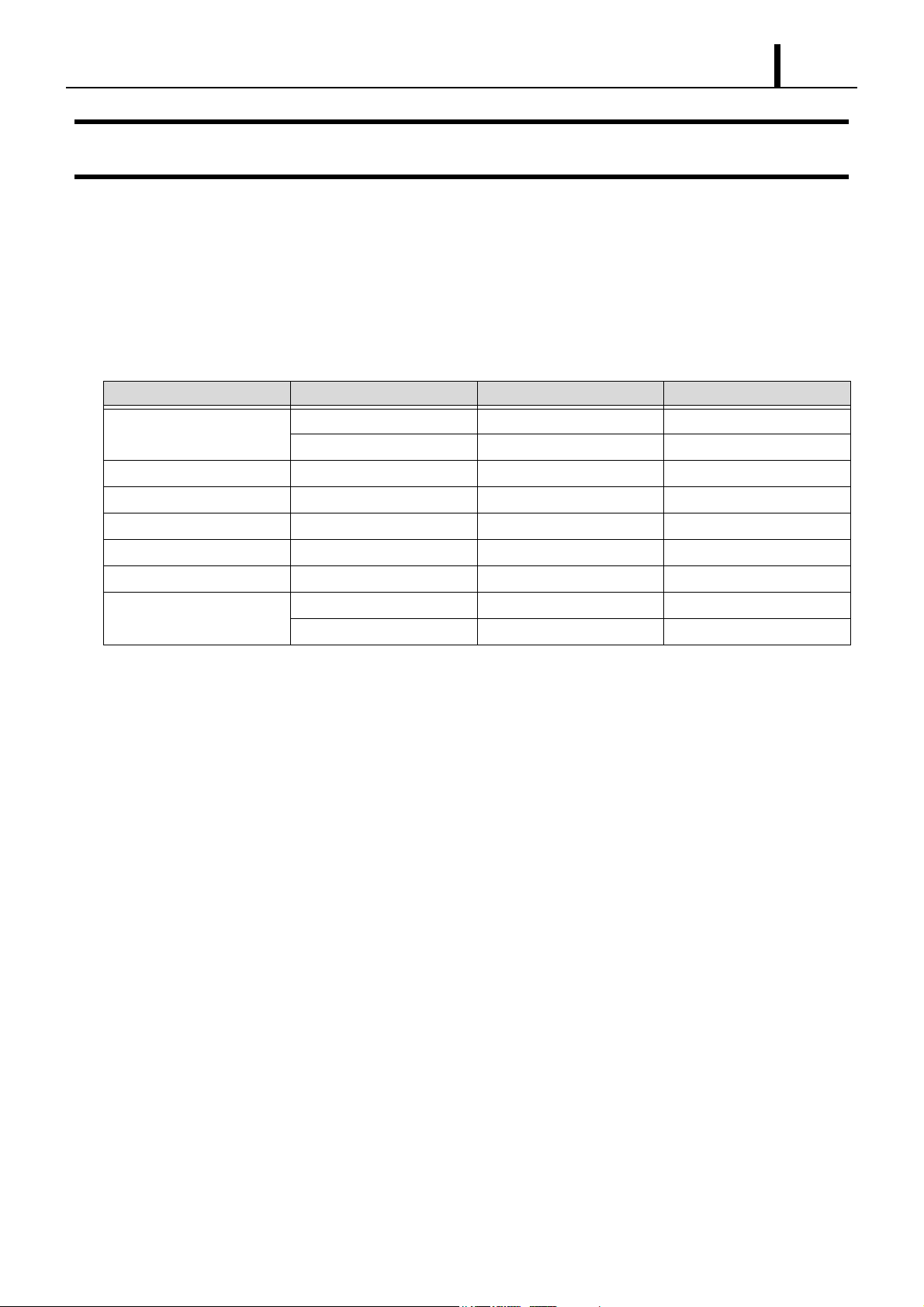
1.2 Functional Parts List
Parts Name DENSO Part Number Manufacturer Parts Number Remarks
Supply pump HU294000-040# 6C1Q-9B395-AB For 2.2L
HU294000-041# 6C1Q-9B395-BB For 2.4L
Fuel temperature sensor 179730-010#
SCV (Suction Control Valve) SM294200-010#
Rail HU095440-073# 6C1Q-9D280-AB
Rail Pressure Sensor HU294390-001#
Pressure Limiter HU095420-033#
Injector HU095000-580# 6C1Q-9K546-AB For low output
HU095000-581# 6C1Q-9K546-BA For high output
Page 5
1–2
Operation Section
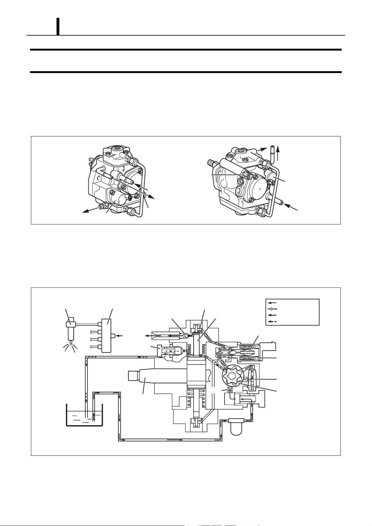
2. SUPPLY PUMP
2.1 Outline
z The supply pump consists primarily of the pump body (camshaft (eccentric cam), ring cam, and plungers), SCV (Suction Control
Valve), fuel temperature sensor, and feed pump.
z The two plungers are positioned vertically on the outer ring cam for compactness.
to Rail
Fuel Temperature
from Fuel Tank
Overflow to
Fuel Tank
to Rail
z The engine drives the supply pump at a ratio of 1:2. The supply pump has a built-in feed pump (trochoid type), and draws the fuel
from the fuel tank, sending it to the plunger chamber.
z The internal camshaft drives the two plungers, and they pressurize the fuel sent to the plunger chamber and send it to the rail. The
quantity of fuel supplied to the rail is controlled by the SCV, using signals from the engine ECU. The SCV is a normally open type
(the SCV opens during de-energization).
Injector
SCV
Rail
Fuel Temperature
Sensor
Discharge Valve
Sensor
Intake Valve
Plunger
Overflow to
Fuel Tank
SCV
from Fuel Tank
Q001030E
Intake Pressure
Feed Pressure
High Pressure
Return
Fuel Tank
Fuel Overflow
Return
Camshaft
Filter
Return Spring
SCV
Regulating Valve
Feed Pump
Fuel Inlet
Intake Fuel Filter
Q001019E
Page 6
Operation Section
(1) Supply Pump Internal Fuel Flow
• Fuel drawn from the fuel tank passes through the route in the supply pump as illustrated, and is fed into the rail.
Supply Pump Interior
Regulating Valve
1–3
Feed Pump
Overflow
Fuel Tank
SCV (Suction Control Valve)
Intake Valve
Pumping Portion (Plunger)
2.2 Construction
z The eccentric cam is formed on the camshaft and is attached to the ring cam.
Camshaft
Eccentric Cam
Discharge Valve
Rail
Q000394E
Ring Cam
Q000395E
z As the camshaft rotates, the eccentric cam rotates eccentrically, and the ring cam moves up and down while rotating.
Plunger
Eccentric cam
Drive shaft
Ring cam
QD0727E
Page 7

1–4
Operation Section
z The plunger and the suction valve are mounted on top of the ring cam. The feed pump is connected to the rear of the camshaft.
Plunger A
Ring cam
Feed pump
Plunger B
QD0728E
Page 8

Operation Section
1–5
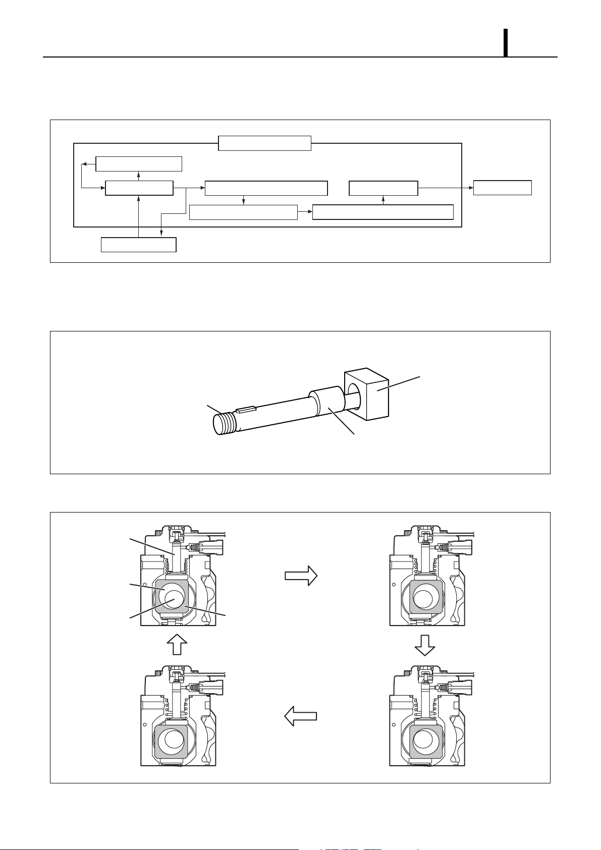
2.3 Operation
z As shown in the illustration below, the rotation of the eccentric cam causes the ring cam to push Plunger A upwards. Due to the spring
force, Plunger B is pulled in the opposite direction to Plunger A. As a result, Plunger B draws in fuel while Plunger A pumps it to the
rail.
Suction valve
Plunger A
SCV
Plunger B
Delivery valve
Plunger A: complete compression
Plunger B: complete intake
Eccentric cam
Ring cam
Plunger A: begin intake
Plunger B: begin compression
Plunger A: begin compression
Plunger B: begin intake
Plunger A: complete intake
Plunger B: complete compression
QD0707E
Page 9

1–6
Operation Section
3. RAIL
3.1 Outline
z The rail stores pressurized fuel that has been delivered from the supply pump and distributes it to each cylinder injector. A pressure
sensor and a pressure limiter are adopted in the rail. The pressure sensor detects the fuel pressure in the rail and sends a signal to the
ECU. The ECU controls the supply pump SCV and the fuel pressure in the rail based on this signal.
Rail Pressure Sensor
To Injector
High-Pressure
Fuel Inlet
Pressure Limiter
Q001054E
Page 10

Operation Section
4. INJECTOR
4.1 Outline
z A compact, energy-saving solenoid-control type TWV (Two-Way Valve) injector has been adopted.
4.2 Construction
16 Base 16 Characters
Sample
1–7
Solenoid Valve
Control Chamber
QR Codes
Sample
Leak Passage
Upper
Side
Pressurized Fuel
(from Rail)
Command Piston
Seat
Pressurized Fuel
Nozzle Spring
Pressure Pin
Filter Orifice Dimensions: φ0.045x2025
Nozzle Needle
Multiple Hole Filter
Q001020E
Page 11

1–8
Operation Section
(1) Injector with QR Codes
QR Code Location
Injection
volume Q
(1)
QR code
Sample
QR Codes
( 9.9mm)
Sample
(2)
(2)
(1)
ID Codes (16 base 16 characters)
Base 16 characters nothing fuel
injection quantity correction
information for market service use.
Sample
Upper
Side
Q001055E
QR Code Correction Points
Pressure parameters
Actuating pulse
Actuating pulse width TQ
TQ
Q001056E
Page 12

Operation Section
1–9
(2) Service Instructions
• When replacing the injectors or the engine ECU, it is necessary to record the ID codes in the ECU using a diagnosis tool (available
from the car manufacturer).
< CAUTION >
If the ID codes for the installed injectors are not registered correctly, engine failure such as rough idling and noise will
result.
Replacing the Injector
"As no correction resistance used, the fuel injection correction data cannot be detected electrically"
Replaced injector
Engine ECU
* Injector ID code must be registered with the engine ECU
Replacing the Engine ECU
"As no correction resistance used, the fuel injection correction data cannot be detected electrically"
Vehicle injectors
Replaced engine ECU
* Injector ID code must be registered with the engine ECU
Q001057E
Q001058E
Page 13

1–10
Operation Section
4.3 Operation
z The TWV (Two-Way Valve) solenoid valve opens and closes the outlet orifice passage to control both the pressure in the control
chamber, and the start and end of injection.
To Fuel
Solenoid
TWV
Outlet Orifice
Actuating
Current
Ta nk
Actuating
Current
Actuating
Current
Inlet Orifice
Control Chamber
Command Piston
Nozzle
Rail
Control
Chamber
Pressure
Injection Rate
Control
Chamber
Pressure
Injection Rate
Control
Chamber
Pressure
Injection Rate
No Injection Injection End of Injection
Q001059E
(1) No injection
• When no current is supplied to the solenoid, the TWV (solenoid valve) is pushed downward by the spring, closing the outlet orifice.
This equalizes the control chamber pressure forcing the command piston down, and the pressure forcing the nozzle needle up. A state
of no injection results because the nozzle needle closes due to the nozzle spring force and the difference in areas to which pressure is
being applied.
(2) Injection
• When current is initially applied to the solenoid, the attraction of the solenoid pulls the TWV (solenoid valve) up, opening the outlet
orifice and allowing fuel to flow out of the control chamber. After the fuel flows out, pressure in the control chamber decreases, pulling
the command piston up. This causes the nozzle needle to rise and injection to start.
(3) Injection Ends
• When current continues to be applied to the solenoid, the nozzle reaches its maximum lift where the injection rate is also at the max-
imum level. When current to the solenoid is turned OFF, the TWV (solenoid valve) falls and closes the orifice. Fuel then flows into
the control chamber via the inlet orifice, increasing pressure and causing the nozzle needle to close immediately and injection to stop.
Page 14

Operation Section
1–11
5. SUPPLY PUMP COMPONENT PARTS
5.1 Feed Pump
z The trochoid type feed pump integrated into the supply pump, draws fuel from the fuel tank and feeds it to the two plungers via the
fuel filter and the SCV (Suction Control Valve). The feed pump is driven by the camshaft. With the rotation of the inner rotor, the feed
pump draws fuel from its suction port and pumps it out through the discharge port. This is done in accordance with the space that
increases and decreases with the movement of the outer and inner rotors.
Outer Rotor
Intake Port
From
Fuel Tank
To
Pump Chamber
Inner Rotor
Discharge
Port
Quantity Decrease
Quantity Increase
Quantity Decrease
(Fuel Discharge)
Quantity Increase
(Fuel Intake)
QD0708E
5.2 SCV (Suction Control Valve)
z A linear solenoid type valve has been adopted. The ECU controls the duty ratio (the duration in which current is applied to the SCV),
in order to control the quantity of fuel that is supplied to the high-pressure plunger.
z The supply pump drive load decreases because intake fuel quantity is controlled to achieve the target rail pressure.
z When current flows to the SCV, the internal armature moves in accordance with the duty ratio. The fuel quantity is regulated by the
cylinder, which moves in connection with the armature to block the fuel passage.
z With the SCV OFF, the return spring pushes the cylinder, completely opening the fuel passage and supplying fuel to the plungers.
(Full quantity intake => full quantity discharge.)
z When the SCV is ON, the return spring contracts and closes the fuel passage.
z By turning the SCV ON/OFF, fuel is supplied in an amount corresponding to the drive duty ratio and then discharged by the plungers.
Valve body
Needle valve Return Spring
Q001060E
Page 15

1–12
Operation Section
(1) When the SCV Energized Duration (Duty ON Time) is Short
• Short duty ON => large valve opening => maximum intake quantity
Feed Pump
Needle valve Large Opening
(2) When the SCV Energized Duration (Duty ON Time) is Long
• Long duty ON => small valve opening => minimum intake quantity
Feed Pump
Q001061E
Needle valve Small Opening
Q001062E
Page 16

Operation Section
(3) Relationship Between the Drive Signal and Current (Magnetomotive Force)
Drive Signal and Current (Magnetomotive Force) Relational Diagram
Low Suction Quantity High Suction Quantity
ON
Voltage
Actuating
OFF
1–13
Current
Average Current Difference
QD0710E
5.3 Fuel temperature sensor
z The fuel temperature sensor is used in rail pressure and injection quantity control. This sensor is installed on the fuel intake side and
utilizes the characteristics of a thermistor in which the electric resistance changes with the temperature in order to detect the fuel tem-
perature.
Initial Resistance Value Characteristics
Temperature
(°C)
Thermistor
Resistance Value
(kΩ)
-30 (25.4)
-20 15.04
+1.29
-1.20
-10 (9.16)
0 (5.74)
10 (3.70)
20
2.45
+0.14
-0.13
30 (1.66)
40 (1.15)
50 (0.811)
60 (0.584)
70 (0.428)
80 0.318±0.008
90 (0.240)
100 (0.1836)
110 0.1417±0.0018
120 (0.1108)
Q001063E
Page 17

1–14
Operation Section
6. RAIL COMPONENT PARTS
6.1 Rail Pressure Sensor
z This sensor detects fuel pressure in the rail and sends a signal to the engine ECU. It is a semi-conductor piezo resistance type pressure
sensor that utilizes the characteristic whereby electrical resistance changes when pressure is applied to a metal diaphragm.
A-VCC = 5V
0 20 100
Rail Pressure (MPa)
160 200
Q001064E
A-VCC PFUEL A-GND
3.56
PFUEL (V)
1.32
4.2
2.6
1.0
0
6.2 Pressure Limiter
z When pressure in the rail is abnormally high, the pressure limiter opens the valve to relieve the pressure. It reopens when pressure in
the rail drops to approximately 200 MPa, and resumes operation when pressure drops to below the specified level. Fuel leaked by the
pressure limiter returns to the fuel tank.
Opening pressure: 200 ± 9MPa
Housing Valve Guide
Valv e
Rail Side
Valve BodySpring
Q001065E
Page 18

Published : February 2006
Edited and published by:
DENSO CORPORATION
Service Department
1-1 Showa-cho, Kariya, Aichi Prefecture, Japan
 Loading...