

Page 1
Page 2
Page 3

Table of Contents
Introductory Information ............................... 1
Safety Restraints .............................................. 9
Starting Your Probe ...................................... 37
Warning Lights and Gauges ....................... 51
Instrument Panel Controls .......................... 63
Steering Column Controls .......................... 77
Features ............................................................ 95
Electronic Sound Systems ......................... 121
Driving Your Probe .................................... 147
Roadside Emergencies ................................ 169
Customer Assistance ................................... 185
Accessories .................................................... 197
Servicing Your Probe ................................. 203
Quick Index
Index ................................................................ 291
Service Station Information....................... 308
.........................................281
Page 4

Introductory Information
At Ford Motor Company, excellence is the
continuous commitment to achieve the best
result possible. It is dedication to learning what
you want, determination to develop the right
concept, and execution of that concept with care,
precision, and attention to detail. In short,
excellence means being the standard by which
others are judged.
Our Guiding Principles
Quality comes first. For your satisfaction, the
❑
quality of our products and services must be
our number one priority.
You are the focus of everything we do. Our
❑
work must be done with you in mind,
providing better products and services than
our competition.
Continuous improvement is essential to our
❑
success. We must strive for excellence in
everything we do: in our products — in their
safety and value — and in our services, our
human relations, our competitiveness, and
our profitability.
Employee involvement is our way of life.
❑
We are a team. We must treat one another
with trust and respect.
Dealers and suppliers are our partners. We
❑
must maintain mutually beneficial
relationships with dealers, suppliers, and our
other business associates.
1
Page 5

Integrity is never compromised. Our conduct
❑
worldwide must be pursued in a manner that
is socially responsible and commands respect
for its integrity and for its positive
contributions to society.
This Guide
Congratulations on the purchase of your new
vehicle. This guide has information about the
equipment and the options for your new vehicle.
You may not have bought all of the options
available to you. If you do not know which
information applies to your vehicle, talk to your
dealer.
This guide describes equipment and gives
specifications for equipment that was in effect
when this guide was approved for printing. Ford
may discontinue models or change specifications
or design without any notice and without
incurring obligation.
NOTES and WARNINGS
NOTES give you additional information about
the subject matter you are referencing.
WARNINGS remind you to be especially careful
in those areas where carelessness can cause
damage to your vehicle or personal injury to
yourself, your passengers or other people. Please
read all WARNINGS carefully.
RWARNING
2
Page 6

Finding Information in This Guide
After you have read this guide once, you will
probably return to it when you have a specific
question or need additional information. To help
you find specific information quickly, you can
use the Quick Index, table of contents, or the
Index.
The Quick Index at the end of the book
provides a page number following each item
which indicates where detailed information can
be found.
This guide has a table of contents at the
beginning of the book to show chapter titles.
To use the Index, turn to the back of the book
and search in the alphabetical listing for the
word that best describes the information you
need. If the word you chose is not listed, think
of other related words and look them up. We
have designed the Index so that you can find
information under a technical term.
Canadian Owners — French Version
French Owner Guides can be obtained from your
dealer or by writing to Ford Motor Company of
Canada, Limited, Service Publications, P.O. Box
1580, Station B, Mississauga, Ontario L4Y 4G3.
Record Booklet
The Maintenance Schedule and Record booklet lists
the services that are most important for keeping
your vehicle in good condition. A record log is
also provided to help you keep track of all
services performed.
3
Page 7

Your vehicle is covered by three types of
warranties: Basic Vehicle Warranty, Extended
Warranties on certain parts, and Emissions
Warranties.
Read your Warranty Information Booklet carefully
to find out about your vehicle’s warranties and
your basic rights and responsibilities.
If you lose your Warranty Information Booklet, you
can get a new one free of charge. Contact any
Ford or Lincoln-Mercury dealer, or refer to the
addresses and phone numbers on the first page
of this owner guide.
Buying a Ford Extended Service Plan
If you bought your vehicle in the U.S., you can
buy a Ford Extended Service Plan for your
vehicle. This optional contract provides service
protection for a longer period of time than the
basic warranty that comes with your vehicle.
You do not have to buy this option when you
buy your vehicle. However, your option to
purchase the Ford Extended Service Plan runs
out after 18 months or 18,000 miles. See your
dealer for more details about the Ford Extended
Service Plan.
If you purchased a Canadian vehicle and did not
take advantage of the Ford Extended Service
Plan at the time of purchase, you may still be
eligible. See your dealer for the details.
4
Page 8

Federal Highway Administration
Regulation
Regulations such as those issued by the Federal
Highway Administration or issued pursuant to
the Occupational Safety and Health Act (OSHA),
and/or state and local laws and regulations may
require additional equipment for the way you
intend to use the vehicle. It is the responsibility
of the registered owner to determine the
applicability of such laws and regulations to
your intended use for the vehicle, and to
arrange for the installation of required
equipment. Your Ford dealer has information
about the availability of many items of
equipment which may be ordered for your
vehicle.
Your new vehicle goes through an adjustment or
break-in period during the first 1,000 miles
(1,600 km) that you drive it. During the break-in
period, you need to pay careful attention to how
you drive your vehicle.
Avoid sudden stops. Because your vehicle
❑
has new brake linings, you should take these
steps:
— Watch traffic carefully so that you can
anticipate when to stop.
— Begin braking well in advance.
— Apply the brakes gradually.
The break-in period for new brake linings
lasts for 100 miles (160 km) of city driving or
1,000 miles (1,600 km) of highway driving.
5
Page 9

Use only the type of engine oil that Ford
❑
recommends. See Engine oil recommendations
in the Index. Do not use special “break-in”
oils.
Vehicle
Washing and Polishing Your Vehicle
Wash the outside of your vehicle, including the
underside, with a mild detergent.
DO NOT:
Wash your vehicle with hot water
❑
Wash your vehicle while it sits in direct
❑
sunlight
Wash your vehicle while the body is hot
❑
Pollen, bird droppings and tree sap can damage
the paint, especially in hot weather. Wash your
vehicle as often as necessary to keep it clean.
Take similar precautions if your vehicle is
exposed to chemical industrial fallout.
Paint damage resulting from fallout is not
related to a defect in paint materials or
workmanship and therefore is not covered by
warranty. Ford, however, believes that continual
improvement in customer satisfaction is a high
priority. For this reason, Ford has authorized its
dealers to repair, at no charge to the owner, the
surfaces of new vehicles damaged by
environmental fallout within 12 months or 12,000
miles (20,000 km) of purchase, whichever comes
first. Customers may be required to bring their
vehicle in for inspection by a Ford
representative.
Polish your vehicle to remove harmful deposits
and protect the finish.
6
Page 10

Cleaning Chrome and Aluminum Parts
Wash chrome and aluminum parts with a mild
detergent. Do not use steel wool, abrasive
cleaners, fuel or strong detergents.
Cleaning Plastic Parts
Some of your vehicle’s exterior trim parts are
plastic. Clean with a tar and road oil remover if
necessary. Use a vinyl cleaner for routine
cleaning.
Do not clean plastic parts with thinners, solvents
or petroleum-based cleaners.
If you have your vehicle rustproofed, remove
oversprayed rustproofing with a tar and road oil
remover. If rustproofing is not removed from
plastic and rubber parts, it can cause
deterioration.
Because your vehicle’s side mouldings are
painted in lacquer, do not use thinners or
solvents to clean them.
7
Page 11

Safety Restraints
The use of safety belts helps to restrain you and
your passengers in case of a collision. In most
states and in Canada the law requires their use.
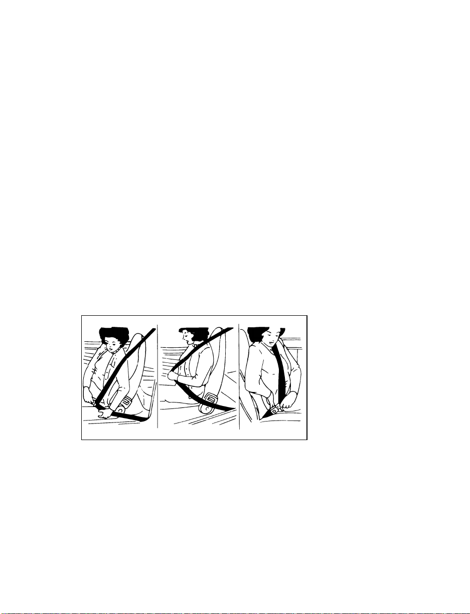
Safety belts provide best restraint when:
the seatback is upright
❑
the occupant is sitting upright (not slouched)
❑
the lap belt is snug and low on the hips
❑
the shoulder belt is snug against the chest
❑
the knees are straight forward
❑
To help you remember to fasten your safety belt,
a warning light may come on and a chime may
sound. See Safety Belt Warning Light/Chime in the
Warning Lights and Gauges chapter.
See the following sections in this chapter for
directions on how to properly use these safety
belts. Also see Safety Restraints for Children in this
chapter for special instructions about using
safety belts for children.
RWARNING
Make sure that you and your passengers
wear safety belts. Always drive and ride
with your seatback upright and the lap
belt snug and low across the hips.
9
Page 12
RWARNING
Never wear the shoulder belt under the
arm. Never swing it around the neck over
the inside shoulder. Never use a single
belt for more than one person or across
more than one seating position. Each
seating position in your vehicle has a
specific safety belt assembly which is
made up of one buckle and one tongue
that are designed to be used as a pair.
Failure to follow these precautions could
increase the risk and/or severity of injury
in a collision.
RWARNING
Ford recommends that all safety belt
assemblies and attaching hardware should
be inspected by a qualified technician
after any collision. Safety belt assemblies
not in use during a collision should also
be inspected and replaced if either
damage or improper operation is noted.
RWARNING
To reduce the risk of serious injury in a
collision, children should always ride with
the seatback upright.
RWARNING
Never let a passenger hold a child on his
or her lap while the vehicle is moving.
The passenger cannot protect the child
from injury in a collision.
Lock the doors of your vehicle before driving to
lessen the risk of the door coming open in a
collision.
10
Page 13
Belts
While your vehicle is in motion, the combination
lap and shoulder belt adjusts to your movement.
However, if you brake hard, turn hard, or if
your vehicle receives an impact of 5 mph
(8 km/h) or more, the lap and shoulder belt
locks and helps reduce your forward movement.
After you get into your vehicle, close the door
and lock it. Then adjust the driver or passenger
seat to the position that suits you best.
Pull the combination lap/shoulder belt from the
retractor so that the shoulder portion of the belt
crosses your shoulder and chest. Be sure the belt
is not twisted. If it is, remove the twist. Insert
the belt tongue into the proper buckle until you
hear a snap and feel it latch. Make sure the
tongue is securely fastened to the buckle by
pulling on tongue.
Fastening the front seat combination lap and shoulder belt
NOTE: Be sure to read and understand
Important Safety Belt Information at
the beginning of this chapter.
11
Page 14
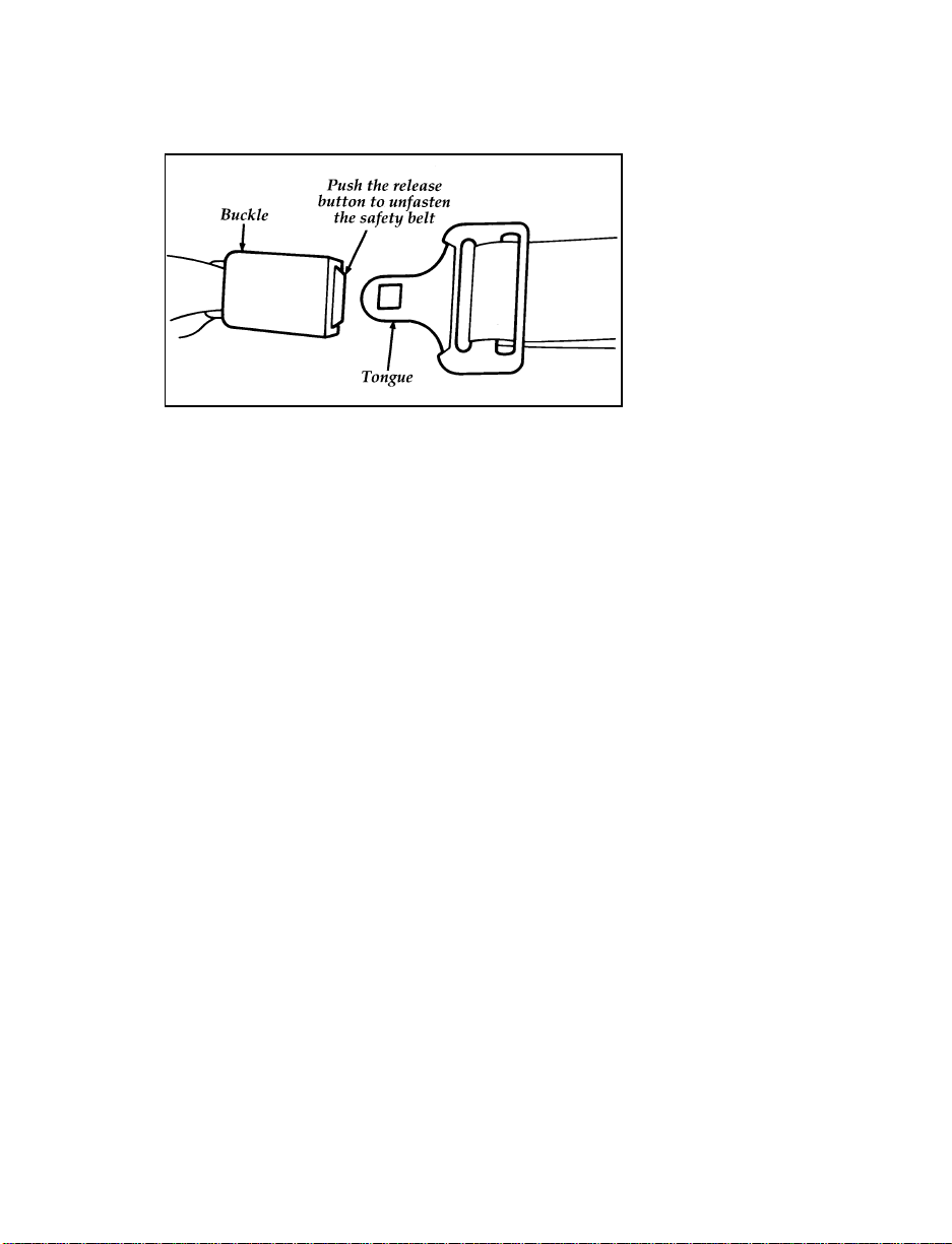
Unfastening the combination lap and shoulder belt — front
and rear seating positions
While the belt retracts, guide the tongue to its
original position to prevent it from striking you
or the vehicle.
Lap/Shoulder Belt Retractors
(Dual Locking Modes)
Your vehicle is equipped with a dual locking
mode retractor on the shoulder belt portion of
the combination lap/shoulder safety belt for all
passengers.
Dual locking mode retractors operate in two
ways:
Vehicle sensitive (emergency) locking mode
In this operating mode, the shoulder belt
retractor will allow the occupant freedom of
movement, locking tight only on hard braking,
hard cornering or impacts of approximately
5 mph (8 km/h) or more. The retractor can also
be made to lock by pulling on the belt.
12
Page 15

Automatic locking mode
In this operating mode, the shoulder belt
retractor will be automatically locked and will
remain locked when the combination
lap/shoulder safety belt is buckled, and does not
allow the occupant freedom of movement. This
mode provides the following:
A tight lap/shoulder belt on the occupant.
❑
Child safety seat installation.
❑
RWARNING
Rear-facing infant seats should never be
placed in the front seats.
This mode must be used when installing a child
seat. To switch the retractor from the emergency
locking mode to the automatic locking mode,
perform the following steps:
1. Buckle the lap/shoulder combination belt.
2. Pull on the belt until all of the stored belt is
out of the retractor and a click is heard.
3. A clicking sound will continue to be heard
as the belt is allowed to retract. This
indicates that the retractor is in the
automatic locking mode.
NOTE: When the combination lap/shoulder
belt is unbuckled and allowed to
retract completely, the retractor will
switch to the vehicle sensitive
(emergency) locking mode. See the
detailed instructions under Safety Seats
for Children in this chapter.
13
Page 16

Safety Belt Extension Assembly
A safety belt that is too short even when fully
extended can be lengthened. You can add about
eight inches (20 cm) to the belt length with a
safety belt extension assembly. Safety belt
extensions are available at no cost from your
dealer.
Use only extensions manufactured by the same
supplier as the safety belt. Manufacturer
identification is located at the end of the
webbing on the label. Also, use the safety belt
extension only if the safety belt is too short for
you when fully extended. Do not use extension
to change the fit of the shoulder belt across the
torso.
RWARNING
Failure to follow these instructions will
affect the performance of the safety belts
and increase the risk of personal injury.
Check the safety belt systems periodically to make
sure that they work properly and are not damaged.
All safety belt assemblies, including retractors,
buckles, front seat belt buckle support assemblies
(slide bar) (if equipped), child safety seat tether
bracket assemblies (if equipped), and attaching
hardware, should be inspected after any
collision. Ford recommends that all safety belt
assemblies used in vehicles involved in a
collision be replaced. However, if the collision
was minor and a qualified technician finds that
the belts do not show damage and continue to
operate properly, they do not need to be
replaced. Safety belt assemblies not in use
during a collision should also be inspected and
replaced if either damage or improper operation
is noted.
14
Page 17

Cleaning the Safety Belts
Clean the safety belts with any mild soap
solution that is recommended for cleaning
upholstery or carpets. Do not bleach or dye the
belt webbing because this may weaken it.
Air Bag Supplemental Restraint
System (SRS)
The driver and right front passenger air bags are
Supplemental Restraint Systems (SRS), provided
at these seating positions in addition to the
lap/shoulder belt, and are designed to
supplement the protection provided to properly
belted occupants in moderate to severe frontal
collisions. The supplemental air bag system does
not provide restraint to the lower body.
The Importance of Wearing Safety Belts
RWARNING
Safety belts must be worn by all vehicle
occupants to be properly restrained and
help reduce the risk of injury in a
collision.
RWARNING
All occupants of the vehicle, including the
driver, should always wear their safety
belts, even when an air bag Supplemental
Restraint System is provided.
15
Page 18
There are four very important reasons to use
safety belts even with an air bag system. Use
your safety belts to:
help keep you in the proper position (away
❑
from the air bag) when it inflates
reduce the risk of harm in rollover, side or
❑
rear impact collisions, because an air bag is
not designed to inflate in such situations
reduce the risk of harm in frontal collisions
❑
that are not severe enough to activate the
supplemental air bag
reduce the risk of being thrown from your
❑
vehicle
The Importance of Being Properly Seated
In a collision, the air bag must inflate extremely
fast to help provide additional protection for
you. In order to do this, the air bag must inflate
with considerable force. If you are not seated in
a normal riding position with your back against
the seatback, the air bag may not protect you
properly and could possibly hurt you as it
inflates.
RWARNING
If a passenger is not properly seated and
restrained, an inflating air bag could cause
serious injury.
RWARNING
Rear-facing infant seats should never be
placed in the front seat.
16
Page 19

In rear-facing infant seats, the infant’s head is
closer to the air bag. The force of the rapidly
inflating air bag could push the top of the
rear-facing seat against the vehicle seatback or
center armrests (if so equipped), or center
console (if so equipped). REAR-FACING
INFANT CARRIERS MUST ALWAYS BE
SECURED IN THE REAR SEAT, and other child
safety seats and infant seats should be secured in
the rear seat whenever possible.
Your vehicle is equipped with a right front
passenger air bag. Air bags deploy with great
force, faster than the blink of an eye. Front
passengers, especially children and small adults,
must never sit on the front edge of the seat,
stand near the glove compartment of the
instrument panel, or lean over near the air bag
cover when the vehicle is moving. All occupants
should sit with their backs against the seatback,
move the seat to the most rearward position if
possible and use the safety belts. Children
weighing less than 40 lbs. (18 kg) always should
use child or infant seats.
RWARNING
When using forward-facing child seats
move the passenger seat as far back from
the instrument panel as possible. NEVER
SECURE REAR-FACING INFANT SEATS
IN THE FRONT SEAT.
17
Page 20

THE FORCE OF THE RAPIDLY INFLATING
PASSENGER AIR BAG COULD PUSH THE TOP
OF THE REAR-FACING SEAT AGAINST THE
VEHICLE SEATBACK, ARMRESTS OR
CONSOLE. REAR-FACING INFANT SEATS
MUST ALWAYS BE SECURED IN THE REAR
SEAT.
RWARNING
Do not place objects or mount equipment
on or near the air bag cover on the
steering wheel or in front seat areas that
may come in contact with a deploying air
bag. Failure to follow this instruction may
increase the risk of personal injury in the
event of a collision.
For additional important safety information on
the proper use of seat belts, child seats, and
infant seats, please read the other sections of this
part of the Owner Guide, especially sections
entitled Safety Belts for Children and Safety Seats
for Children.
How the Air Bag Supplemental Restraint
System Operates
The Air Bag Supplemental Restraint System
consists of the driver and passenger air bags,
impact sensors, a system diagnostic module, a
readiness light and tone, and the electrical
wiring which connects the components.
The driver air bag is in the center of the steering
wheel. The front passenger seat air bag is
located in the center of the instrument panel
ledge above the glove compartment. Both air
bags are designed to stay out of sight until they
are activated.
18
Page 21

The location of the air bag and warning labels
If a collision occurs, the sensors sense the
severity of the impact and activate the air bags if
necessary. The air bag system is designed to
deploy in frontal and front-angled collisions
more severe than hitting a parked vehicle (of
similar size and weight) head-on at about
28 mph (45 km/h). Because the system senses
the crash severity rather than vehicle speed,
some frontal collisions at speeds above 28 mph
(45 km/h) will not inflate the air bag.
19
Page 22
When the sensors activate the system, the air
bags inflate rapidly, filling with non-toxic
nitrogen gas in a fraction of a second.
Immediately after inflation, the air bags deflate
by releasing the nitrogen gas through vent holes.
The whole process takes place in a matter of
seconds.
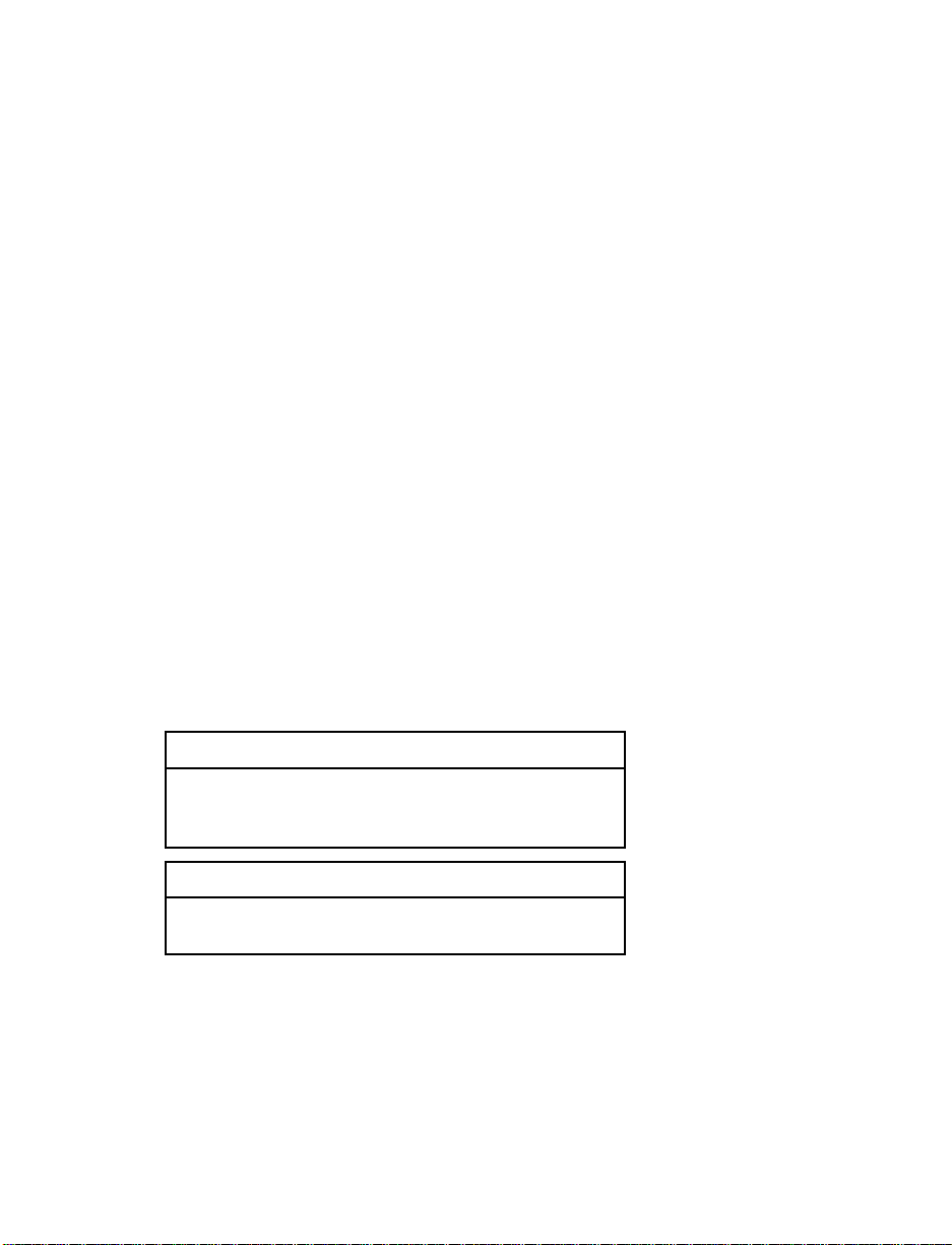
RWARNING
Air bag system components get hot after
inflation. Do not touch them after
inflation.
Inflated driver-side air bag
20
Page 23
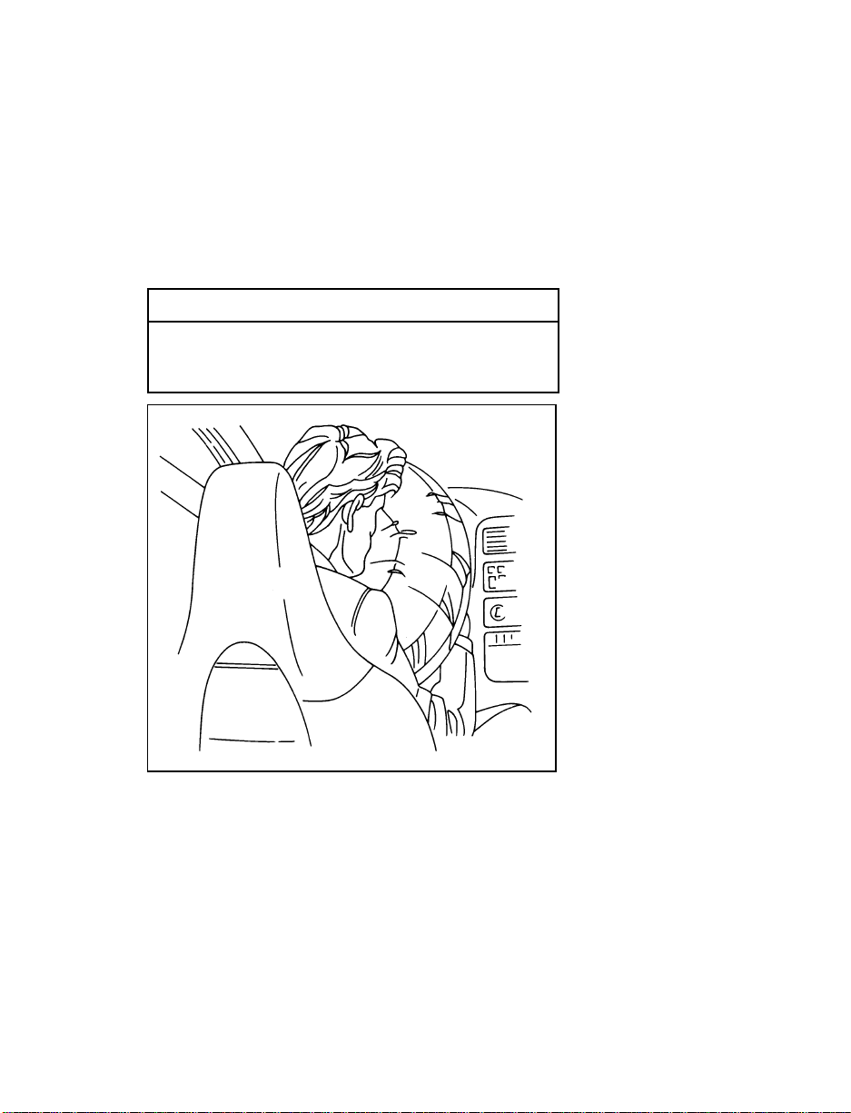
Inflated passenger-side air bag
RWARNING
If the air bag is inflated, THE AIR BAG
WILL NOT FUNCTION AGAIN AND
MUST BE REPLACED IMMEDIATELY. If
the air bag is not replaced, the unrepaired
area will increase the risk of injury in a
collision.
To ensure that the air bag system will operate as
intended in a crash, the system is equipped with
a diagnostic module. The diagnostic module
monitors its own circuits, the air bag electrical
system, the air bag readiness light, the air bag
power, and the air bag inflators.
21
Page 24

The air bag system uses a readiness light on the
instrument cluster and a tone to indicate the
condition of the system. When you turn the
ignition key to the ON position, this light will
illuminate for approximately six (6) seconds and
then turn off. This indicates that the system is
operating normally. NOTE: Maintenance of the
air bag system is not required.
A problem with the system is indicated by one
or more of the following:
the readiness light will either flash or stay lit,
❑
or it will not light immediately after ignition
❑
is turned on,
or a group of five beeps will be heard. The
❑
tone pattern will repeat periodically until the
problem and light are repaired.
If any of these things happen, have the air bag
system serviced at your Ford or Lincoln-Mercury
dealer immediately. Unless serviced, the air bag
supplemental restraint system may not function
properly in the event of a collision.
RWARNING
Do not attempt to service, repair, or
modify the Air Bag Supplemental
Restraint System or its fuses. See your
Ford or Lincoln-Mercury dealer.
Disposal of air bags or air bag equipped
vehicles
For disposal of air bags or air bag equipped
vehicles, see your local Ford or Lincoln-Mercury
dealer. Air bags MUST be disposed of by
qualified personnel.
22
Page 25
In the U.S. and Canada, you are required by law
to use safety restraints for children. If small
children ride in your vehicle — this generally
includes children who are four years old or
younger and who weigh 40 pounds (18 kg) or
less — you must put them in safety seats that
are made specially for children. Safety belts
alone do not provide maximum protection for
these children. Check your local and state laws
for specific requirements.
RWARNING
Never let a passenger hold a child on his
or her lap while the vehicle is moving.
The passenger cannot protect the child
from injury in a collision.
RWARNING
To prevent the risk of injury, make sure
children sit where they can be properly
restrained.
RWARNING
Passengers should not be allowed to ride
in the cargo area. Persons not riding in a
seat with a fastened seat belt are much
more likely to suffer serious injury in a
collision. Cargo should always be secured
to prevent it from shifting and causing
damage to the vehicle or harm to
passengers.
23
Page 26
When possible, put children in the rear seat of
your vehicle. Accident statistics suggest that
children are safer when properly restrained in
the rear seating positions than in the front
seating positions.
RWARNING
Carefully follow all of the manufacturer’s
instructions included with the safety seat
you put in your vehicle. If you do not
install and use the safety seat properly,
the child may be injured in a sudden stop
or collision.
RWARNING
Safety belts and seats can become hot in a
vehicle that has been closed up in sunny
weather; they could burn a small child.
Check seat covers and buckles before you
place a child anywhere near them.
RWARNING
Never leave a child unattended in your
vehicle.
24
Page 27

Safety Seats for Children
Use a safety seat that is recommended for the
size and weight of the child. Always follow the
safety seat manufacturer’s instructions when
installing and using the safety seat.
Ford recommends the use of a child safety seat
having a top tether strap. Install the child safety
seat in a seating position which is capable of
providing a tether anchorage. For more
information on top tether straps see Attaching
Safety Seats With Tether Straps in this chapter.
When installing a child safety seat, be sure to
use the correct safety belt buckle for that seating
position, and make sure the tongue is securely
fastened in the buckle.
Your vehicle is equipped with a right front
passenger air bag. Air bags deploy with great
force, faster than the blink of an eye. Front
passengers, especially children and small adults,
must never sit on the front edge of the seat,
stand near the glove compartment of the
instrument panel, or lean over near the air bag
cover when the vehicle is moving. All occupants
should sit with their backs against the seatback,
move the seat to the most rearward position if
possible and use the safety belts. Children
weighing less than 40 lbs. (18 kg) always should
use child or infant seats.
25
Page 28

RWARNING
When using forward-facing child seats
move the passenger seat as far back from
the instrument panel as possible. NEVER
SECURE REAR-FACING INFANT SEATS
IN THE FRONT SEAT.
THE FORCE OF THE RAPIDLY INFLATING
PASSENGER AIR BAG COULD PUSH THE TOP
OF THE REAR-FACING SEAT AGAINST THE
VEHICLE SEATBACK, ARMRESTS OR
CONSOLE. REAR-FACING INFANT SEATS
MUST ALWAYS BE SECURED IN THE REAR
SEAT.
All child restraint systems are designed to be
secured in vehicle seats by lap belts or by the
lap portion of a lap-shoulder belt.
RWARNING
If you do not properly secure the safety
seat, the child occupying the seat may be
injured during a collision or sudden stop.
An unsecured safety seat could also injure
other passengers.
RWARNING
Carefully follow all of the manufacturer’s
instructions included with the safety seat
you put in your vehicle. If you do not
install and use the safety seat properly,
the child may be injured in a sudden stop
or collision.
26
Page 29

Installing Child Safety Seats
Your vehicle is equipped with a dual locking
mode retractor on the shoulder belt portoin of
the front passenger seat and both rear seats. The
automatic locking mode must be used when
installing a child seat or infant carrier in the
front passenger seat or rear seats.
RWARNING
Never install a rear-facing child seat or
infant carrier in the right front passenger
seat.
If you install a child safety seat or infant carrier
in any of the seating positions, you must follow
the proper procedures:
1. Position the child seat or infant carrier on
the passenger seat of the vehicle.
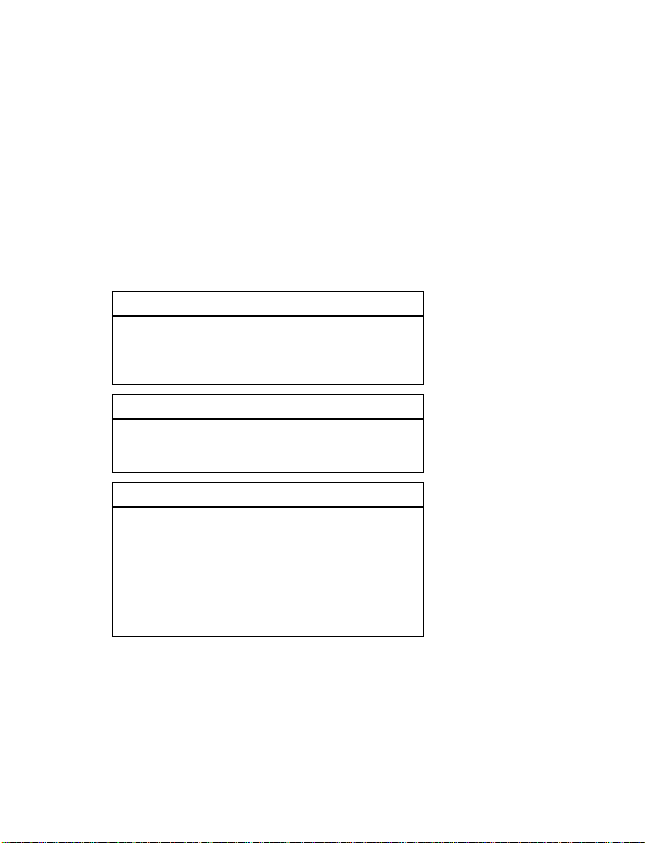
2. Pull down on the shoulder belt, then grasp
the shoulder belt and lap belt together.
27
Page 30
Grasping lap and shoulder belt together
3. While holding the shoulder and lap belt
portions together, route the tongue through
the child seat according to the child seat
manufacturer’s instructions. Be sure the belt
webbing is not twisted.
28
Page 31

Routing safety belt through child seat or infant carrier
Buckling the belt
29
Page 32
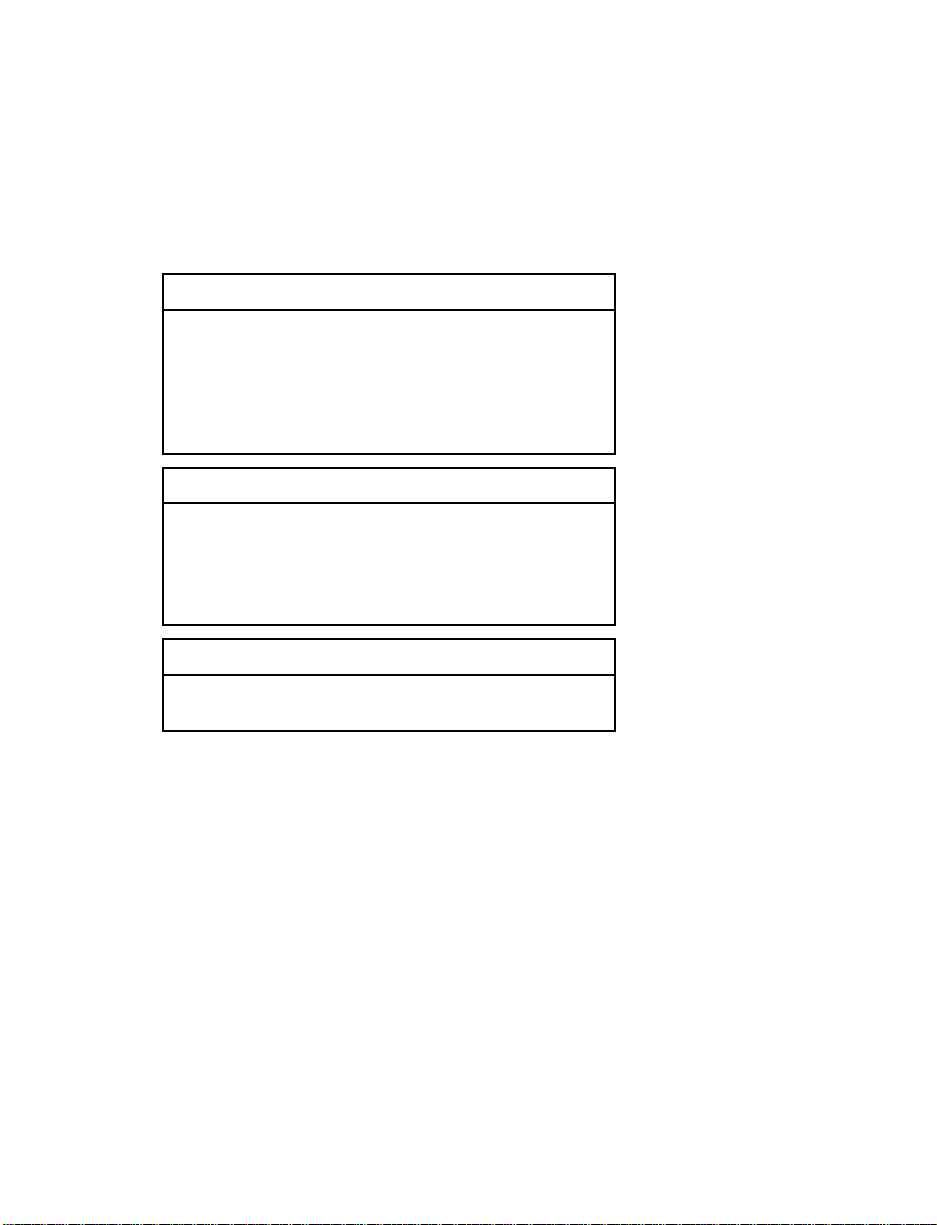
4. Grasp the shoulder portion of the belt and
pull downward until all of the belt is
extracted and a click is heard. At this time,
the retractor is in the automatic locking
mode (child seat restraint mode).
Setting the retractor to automatic locking mode
5. Allow the belt to retract. Pull up on the
shoulder webbing. A clicking sound will be
heard as the belt retracts. This indicates that
the retractor is in the automatic locking
mode. Push down on the child seat while
you pull up on the belt webbbing to remove
any slack in the belt.
30
Page 33

Removing slack from belt
6. Before placing the child in the child seat or
infant carrier, forcibly tilt the seat from side
to side, and tug it forward to make sure that
the seat is securely held in place.
31
Page 34

Checking that the seat is secure
7. Double check that the retractor is in the
automatic locking mode. Try to pull more
belt out of the retractor. If you cannot, the
belt is in the automatic locking mode.
32
Page 35

Checking the retractor
8. Check to make sure that the child seat or
infant carrier is properly secured prior to
each use. If the belt is not locked, repeat
steps 4 through 7.
NOTE: To remove the retractor from automatic
lock mode, allow seat belt retract fully
to its stowed position and the retractor
will automatically switch back to the
vehicle sensitive locking mode for
normal adult usage.
33
Page 36

RWARNING
When using any infant or child restraint
system, it is important that you follow the
instructions and warnings provided by the
manufacturer concerning its installation
and use. Failure to follow each of the
restraint manufacturer’s instructions could
increase the risk or severity of an injury
in the event of a collision or sudden stop.
Attaching Safety Seats With Tether Straps
Some manufacturers make safety seats that
include a tether strap that goes over the back of
the vehicle seat and attaches to an anchoring
point. Other manufacturers offer the tether strap
as an accessory. Contact the manufacturer of
your child safety seat for information about
ordering a tether strap.
Front Seats
To install a tether from a child safety seat in the
front seat:
1. Buckle the lap/shoulder belt (in the seat
directly behind the front passenger seat in
which the child safety seat will be installed).
2. Pull all the stored belt out of the rear seat
retractor to switch the retractor to automatic
locking mode.
3. Let the retractor wind up the slack from the
lap/shoulder belt.
4. Install the child safety seat in the front seat.
Refer to the previous section on Installing
Safety Seats. Hook the tether strap hook
around the webbing near the center of the
shoulder portion of the locked lap/shoulder
belt.
5. Tighten the tether strap.
34
Page 37

Rear Seats
If you use a tethered safety seat on one of the
rear seats, install a tether anchor bracket to one
of the two 0.3 inch (8 mm) weld nuts on the
rear of the cargo area below the opening for the
liftgate.
Tether Anchorage Hardware
Tether anchor hardware kits can be obtained at
no charge from any Ford or Lincoln-Mercury
dealer.
Be sure to follow the child safety seat
manufacturer’s instructions.
RWARNING
Tighten the anchor according to
specifications. Otherwise, the safety seat
may not be properly secured and the child
may be injured in a sudden stop or
collision.
Installing the Anchor Bracket
1. Open the liftgate and take out the luggage
compartment cover (if equipped).
2. The anchorage nuts used to secure the tether
anchor are located in the rear body panel
behind the trim at the rear of the luggage
compartment. Remove the trim panel. The
backside of the panel is scored at the
locations of the anchorage nuts. Make a hole
the size of the scoring in the trim panel to
provide access to the anchor nut. The hole
should be made on the same side of the
vehicle as the child safety seat will be
located. Reinstall the trim panel.
35
Page 38

3. Install the hardware for anchoring the tether
following the instructions in the tether
anchorage hardware kit.
4. Re-install luggage compartment cover.
Installing the anchor bracket
36
Page 39

Starting Your Probe
Understanding the Positions of the Ignition
Ignition lock cylinder
LOCK locks the steering wheel. It also locks the
gearshift lever in P (Park) (automatic transaxle).
LOCK is the only position that allows you to
remove the key. The LOCK feature helps to
protect your vehicle from theft.
To remove the key if you have a manual
transaxle, push the key in while turning it to the
LOCK position.
If your key is stuck in the LOCK position and
will not turn, move your steering wheel left or
right until the key turns freely.
ACC (Accessory) allows some of your vehicle’s
electrical accessories to operate while the engine
is not running.
37
Page 40

ON allows you to test your vehicle’s warning
lights (except the brake system warning light) to
make sure they work before you start the
engine. The key returns to the ON position once
the engine is started and remains in this position
while the engine runs.
START cranks the engine. Release the key once
the engine starts so that you do not damage the
starter. The key should return to ON when you
release it. The START position also allows you
to test the brake warning light.
Shift-lock System
For your safety, the optional automatic transaxle
has the shift-lock system, which prevents shifting
the transaxle out of the P (Park) position without
depressing the brake pedal when the ignition
switch is in the ON position.
To shift the transaxle out of the P (Park)
position:
1. Depress and hold the brake pedal.
2. Start the engine.
3. Push in the thumb button and move the
shift selector lever.
4. See Shift Lock Emergency Override in this
section for more information.
38
Page 41
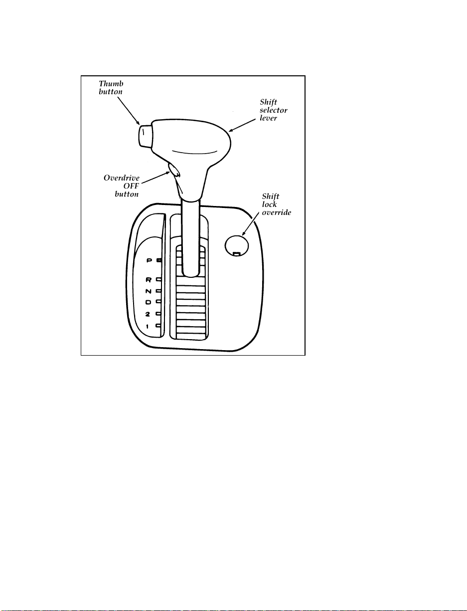
Automatic console-mounted gearshift lever
NOTE: When the ignition key is in the ACC
or LOCK position, the transaxle cannot
be shifted from the P (Park) position.
If the brake pedal is repeatedly
depressed and released when the
ignition is in the ON position and the
selector lever is in the P (Park)
position, a chattering near the gearshift
lever may be heard. This is not a
malfunction.
39
Page 42

NOTE: Your vehicle’s gearshift lever is
securely latched in P (Park) if you
cannot move it without pushing in the
thumb button. Keep the brake pedal
depressed while moving your gearshift
lever.
To make the system more effective, the ignition
key cannot be removed unless the gearshift
selector lever is in the P (Park) position.
Shift lock emergency override
If the gearshift selector lever should fail to move
from the P (Park) position with the brake pedal
depressed, continue depressing the brake pedal.
1. Remove the shift lock override cover with a
screwdriver.
2. Insert the screwdriver into the shift lock
override opening and push the screwdriver
handle down.
3. Push and hold the thumb button.
4. Move the shift selector lever.
If you need to shift out of P (Park) by using the
alternate procedure described above, it is
possible that a fuse has blown and that your
brakelamps may also not be functional. Please
refer to the chapter titled Servicing Your Probe in
this Owner Guide for instructions on checking
and replacing fuses.
RWARNING
DO NOT DRIVE YOUR VEHICLE UNTIL
YOU VERIFY THAT THE BRAKELAMPS
ARE WORKING.
40
Page 43

Removing the Key From the Ignition
1. Put the gearshift selector lever in P (Park)
(automatic transaxle) or 1 (First) (manual
transaxle).
2. Set the parking brake fully.
3. For a manual transaxle: Push in on the lock
cylinder and turn the key from ACC to
LOCK.
LOCK.
4. Remove the key.
If the driver or passenger door is open while the
key is still in the ignition, a warning chime
sounds.
RWARNING
Always set the parking brake fully and
make sure that the gearshift is securely
latched in P (Park) (automatic transaxle) or
in 1 (First) (manual transaxle).
RWARNING
Do not leave children, unreliable adults,
or pets alone in your vehicle. They could
accidentally injure themselves or others
through inadvertent operation of the
vehicle. Further, on hot, sunny days,
temperatures in a closed vehicle could
quickly become high enough to cause
severe and possibly fatal injuries to
people as well as animals.
41
Page 44

When starting a fuel-injected engine, the most
important thing to remember is to avoid
pressing down on the accelerator before or
during starting. Only use the accelerator when
you have problems getting your vehicle started.
See Starting Your Engine in this chapter for
details about when to use the accelerator while
you start your vehicle.
Preparing to Start Your Vehicle
RWARNING
Do not start your vehicle in a closed
garage or other enclosed area. Never sit in
a stopped vehicle for more than a short
period of time with the engine running.
Exhaust fumes are toxic. See Guarding
Against Exhaust Fumes in this chapter for
more instructions.
Before you start your vehicle, do the following:
1. Make sure you and all your passengers
buckle your safety belts. See Safety Restraints
in the Index for more details.
2. Make sure the headlamps and other
accessories are turned off when starting.
3. If you have an automatic transaxle, make
sure that the gearshift is in P (Park) and the
parking brake is set before you turn the key.
that the parking brake is fully set, push the
clutch pedal to the floor, and put the
gearshift into Neutral before you turn the
key. (Remember, the starter will operate
only if the clutch pedal is pushed all the
way to the floor.)
42
Page 45

Testing the Warning Lights
Before you start your vehicle, you should test
the warning lights on the instrument panel to
make sure that they work. Refer to the Warning
Lights and Gauges chapter.
Starting Your Engine
To start your engine:
1. Follow the steps under Preparing to Start
Your Vehicle at the beginning of this section.
2. Keep your foot on the brake pedal and turn
the ignition key to the ON position.
3. DO NOT depress the accelerator pedal when
starting your engine. DO NOT use the
accelerator while the vehicle is parked.
4. Turn the key to the START position
(cranking) until the engine starts. Allow the
key to return to the ON position after the
engine has started.
rotate the steering wheel slightly because it
may be binding.
For a cold engine:
At temperatures 10˚F (-12˚C) and below: If
❑
the engine does not start in fifteen (15)
seconds on the first try, turn the key to OFF,
wait approximately ten (10) seconds so you
do not flood the engine, then try again.
At temperatures above 10˚F (-12˚C): If the
❑
engine does not start in five (5) seconds on
the first try, turn the key to OFF, wait
approximately ten (10) seconds so you do not
flood the engine, then try again.
43
Page 46

For a warm engine:
Do not hold the key in the START position
❑
for more than five (5) seconds at a time. If
the engine does not start within five (5)
seconds on the first try, turn the key to the
OFF position. Wait a few seconds after the
starter stops, then try again.
Whenever you start your vehicle, release the key
as soon as the engine starts. Excessive cranking
could damage the starter or flood the engine.
After you start the engine, let it idle for a few
seconds. Keep your foot on the brake pedal and
put the gearshift lever in gear. Release the
parking brake. Slowly release the brake pedal
and drive away in the normal manner.
NOTE: Your vehicle is equipped with an
automatic transaxle that has an
interlock that prevents you from
shifting out of P (Park) unless your
foot is on the brake pedal.
If the engine does not start after two attempts:
1. Turn the ignition key to the OFF position.
2. Press the accelerator all the way to the floor
and hold it.
3. Turn the ignition key to the START position.
4. Release the ignition key when the engine
starts.
5. Release the accelerator gradually as the
engine speeds up. Then drive away in the
normal manner.
If the engine still does not start, the fuel pump
shut-off switch may have been triggered. For
directions on how to reset the switch see Fuel
Pump Shut-Off Switch later in this chapter.
44
Page 47

A computer system controls the engine’s idle
speed. When you start your vehicle, the engine’s
idle speed normally runs high. These faster
engine speeds will make your vehicle move
slightly faster than its normal idle speed. It
should, however, slow down after a short time.
If it does not, have the idle speed checked.
If the engine idle speed does not slow down
automatically, do not allow your vehicle to idle
for more than 10 minutes. Have the vehicle
checked.
RWARNING
Extended idling at high engine speeds can
produce very high temperatures in the
engine and exhaust system, creating the
risk of fire or other damage.
RWARNING
Do not park, idle, or drive your vehicle in
dry grass or other dry ground cover. The
emission system heats up the engine
compartment and exhaust system, which
can start a fire.
Engine Block Heater (If equipped)
Engine block heaters are strongly recommended
if you live in a region where temperatures reach
-10˚F (-23˚C) or below. An engine block heater
warms the engine coolant, which improves
starting, warms up the engine faster, and allows
the heater-defrost system to respond quickly.
To turn the heater on, simply plug it into a
grounded 110-volt outlet. Ford recommends that
you use a 110-volt circuit that is protected by a
ground fault circuit interrupter.
45
Page 48

RWARNING
To prevent electrical shock, do not use
your heater with ungrounded electrical
systems or two-pronged (cheater) adapters.
For best results, plug the heater in at least three
hours before you start your vehicle. Using the
heater for longer than three hours will not
damage the engine, so you can plug it in at
night to start your vehicle the following
morning.
Not Start or Does Not Start After
a Collision
The Fuel Pump Shut-off Switch
If the engine cranks but does not start or does
not start after a collision, the fuel pump shut-off
switch may have been triggered. The shut-off
switch is a device intended to stop the fuel
pump when your vehicle has been involved in a
substantial jolt.
Once the shut-off switch is triggered, you must
reset the switch by hand before you can start
your vehicle.
46
Page 49

The location of the fuel pump shut-off switch
RWARNING
If you see or smell fuel, do not reset the
switch or try to start your vehicle. Have
all the passengers get out of the vehicle
and call the local fire department or a
towing service.
47
Page 50

If your engine cranks but does not start after a
collision or substantial jolt:
1. Turn the key in the ignition to the LOCK
position.
2. Check under the vehicle for leaking fuel.
3. If you do not see or smell fuel, push the red
reset button on the fuel pump shut-off
switch down.
The reset switch on your vehicle is located on
the left side of the luggage compartment
under the carpet. The red reset button is
under the raised area of the rubber cover.
4. Attempt to start your vehicle. If the vehicle
starts, let it run a few seconds, then turn the
key to the LOCK position.
5. Check under the vehicle again for leaking
fuel. If you see or smell fuel, do not start
your vehicle again. If you do not see or
smell fuel, you can try to start your vehicle
again.
Guarding Against Exhaust Fumes
Carbon monoxide, although colorless and
odorless, is present in exhaust fumes. Take
precautions to avoid its dangerous effects.
RWARNING
Do not start your vehicle in a closed
garage or other enclosed area. Never sit in
a stopped vehicle for more than a short
period of time with the engine running.
Exhaust fumes are toxic. See Guarding
Against Exhaust Fumes in this chapter for
more instructions.
48
Page 51

RWARNING
If you smell exhaust fumes inside your
vehicle, have your dealer inspect your
vehicle immediately. Do not drive if you
smell exhaust fumes.
Have the exhaust and body ventilation systems
checked whenever:
your vehicle is raised for service
❑
the sound of the exhaust system changes
❑
your vehicle has been damaged in a collision
❑
Improve your ventilation by keeping all air inlet
vents clear of snow, leaves, and other debris.
If the engine is idling while you are stopped in
an open area for long periods of time, open the
windows at least one inch (2.5 cm). Also, adjust
the heating or air conditioning to bring in
outside air.
If you are using the heater, set the fan speed
❑
on MEDIUM or HIGH with the function
selector control on VENT.
If you want to use the air conditioner, set the
❑
function selector control in the NORM A/C
position which brings in fresh air.
49
Page 52

Warning Lights and Gauges
The instrument panel (dashboard) on your
vehicle is divided into several different sections.
The illustrations on the following pages show
the major parts of the instrument panel that are
described in this chapter. Some items shown
may not be on all vehicles.
In your vehicle, the warning lights and gauges
are grouped together on the instrument panel.
We call this grouping a cluster.
To clean the lenses on your instrument panel,
use Ford Glass Cleaner and a soft cloth. Never
use paper towels or abrasive cleaners; they can
scratch the lenses.
Your vehicle has a mechanical cluster.
51
Page 53

52
Mechanical cluster
Page 54

53
Warning light locations on the mechanical cluster
Page 55
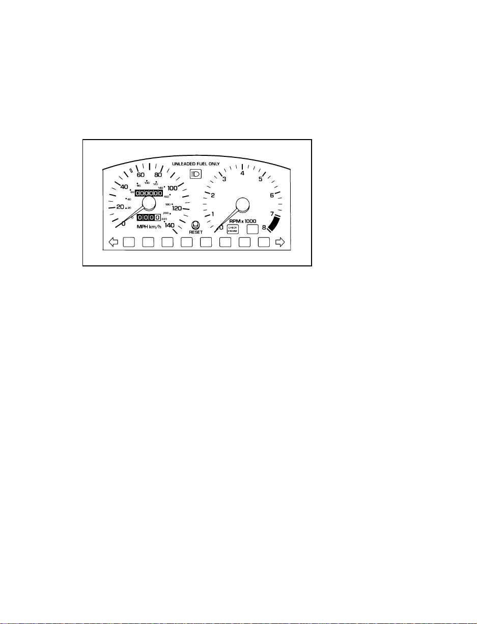
The mechanical cluster on the Probe GT model is
similar to the one shown. The two exceptions
are: the speedometer on the GT model shows
140 mph (225 km/h) and it has a 7,000 rpm
red-line tachometer.
GT model speedometer and tachometer
The following warning lights and gauges are on
the cluster. All of the warning lights and gauges
alert you to possible problems with your vehicle.
The following sections detail what each of these
indicators means.
Safety Belt Warning Light and Chime
This warning light and chime remind you to
fasten your safety belt. If you do not fasten your
safety belt before the ignition is turned to ON,
the chime will sound for 4 to 8 seconds and the
warning light will illuminate for 1 to 2 minutes,
or until the safety belt is fastened. If you fasten
the safety belt before the ignition is turned to
ON, neither the light nor chime will activate.
54
Page 56
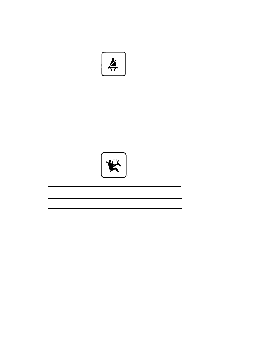
Safety belt light
Air Bag Readiness Light
This light illuminates for six seconds when the
ignition is turned to the ON position. If the light
fails to illuminate, continues to flash, remains on,
or if a series of five beeps is heard, have the
system serviced as soon as possible.
Air bag readiness light
RWARNING
If any of these things happen, even
intermittently, have the air bag system
serviced at your Ford or Lincoln-Mercury
dealer immediately.
Brake System Warning Light
Your vehicle has a divided brake system. If one
part isn’t working, the other part can still work
and stop you. For good braking, though, you
need both systems working well. If the warning
light goes on, there could be a problem. Have
your brake system inspected right away.
55
Page 57

This light should come on as you start the
vehicle. If it doesn’t come on then, have it fixed
so it will be ready to warn you if there’s a
problem.
Brake system and parking brake light
This light comes on briefly when you turn the
ignition key to START. It normally goes off
shortly after the engine starts and you release
the parking brake, but it may stay on for up to
60 seconds. If the light stays on for longer than
60 seconds or comes on after you have fully
released the parking brake, have the hydraulic
brake system serviced.
This light will also come on if the parking brake
does not release fully. If it does stay on after the
parking brake is fully released, it means there
may be a brake problem. Pull off the road and
stop carefully. You may notice that the pedal is
harder to push, the pedal may go closer to the
floor, or it may take longer to stop the vehicle.
Try the brakes again after you have stopped.
RWARNING
The BRAKE light indicates that the brakes
may not be working properly. Have the
brakes checked immediately.
56
Page 58

Anti-Lock Brake System Warning Light
When the ignition switch is turned to the ON
position, the anti-lock brake system warning
light will come on. When the engine is started,
the anti-lock brake system control unit will
determine if all components of the system are
operating correctly. The warning light could
remain on for two to four seconds.
The anti-lock brake system warning light
RWARNING
If the anti-lock brake system warning
light remains on or comes on while
driving, have the braking system checked
by a qualified service technician as soon
as possible.
NOTE: If a fault occurs in the anti-lock
system, and the brake warning light is
not lit, the anti-lock system is disabled
but normal brake function remains
operational.
NOTE: If your vehicle must be jump-started
because of a low battery, the anti-lock
brake system warning light could
remain on. This is due to low battery
voltage and does not indicate a
malfunction in the system. Under these
circumstances, you should drive your
vehicle only after the battery has had
time to charge and the light has gone
out.
57
Page 59

The Low Fuel Light
This light comes on when fuel level in your tank
has reached approximately 2-3 gallons (7-10
liters).
Low fuel light
High Beam Light
This light comes on when the headlamps are
turned to high beam or when you flash the
lights.
High beam light
Check Engine Warning Light
This light comes on when the electronic engine
control system is not working properly. This is
the computer system that controls the operating
conditions of the engine.
Check engine warning light
58
Page 60

This light comes on briefly when you turn the
ignition to the ON position, but should turn off
when the engine starts. If the light does not
come on when you turn the ignition to the ON
position or if it comes on and stays on when
you are driving, have your vehicle serviced as
soon as possible. This indicates a possible
problem with one of the engine’s emission
control systems. You do not need to have your
vehicle towed in.
If the light turns on and off briefly while you
are driving, it means that the condition is no
longer present.
O/D OFF Light (If equipped)
This light tells you that the overdrive off (O/D
OFF) button on the shift selector has been
pushed. When the light is on, the transaxle will
not shift into overdrive. Depressing the button
on the shift selector again will return the vehicle
to “overdrive on” mode. The transaxle will be in
the “overdrive on” mode when the vehicle is
started even if the O/D OFF mode was selected
when the vehicle was last shut off.
If the light does not come on when the O/D
OFF button is pressed, or if the light flashes
when you are driving, have your vehicle
serviced at the first opportunity. If this condition
persists, damage could occur to the transaxle.
Overdrive OFF light
59
Page 61

Fuel Gauge
The fuel gauge displays approximately how
much fuel you have in the fuel tank.
The ignition must be turned off while putting
fuel in the tank in order to get a correct fuel
gauge reading after the ignition is turned on.
The fuel gauge indicator may vary slightly while
the vehicle is in motion. This is the result of fuel
movement within the tank. You can get a more
accurate reading with the vehicle on smooth,
level ground.
Charging System Gauge
This gauge tells you your battery’s voltage when
you turn your ignition key to ON. When you
start your engine, the pointer should move to
the NORMAL range if you are not operating
any electrical accessories. (If electrical accessories
are operating and the engine is not running, the
pointer may move into the red area).
If the pointer moves into the red area when no
electrical accessories are operating, have the
vehicle’s electrical system checked.
Engine Oil Pressure Gauge
The gauge needle should stay in the NORMAL
range (indicating normal engine oil pressure). If
the needle drops below the NORMAL range into
the low range, there is a loss of oil pressure.
If this happens:
1. Pull off the road as soon as safely possible.
2. Shut off the engine immediately or severe
engine damage could result.
60
Page 62

3. Check the oil level when the vehicle is on
level ground.
4. Add only as much oil as the engine needs
before you drive the vehicle again. Do not
overfill the oil reservoir. For more
information, see Adding engine oil in the
Index.
Engine Coolant Temperature Gauge
This gauge indicates the temperature of the
engine coolant, not the coolant level. If the
coolant is not at its proper level or mixture, the
gauge indication will not be accurate.
The pointer usually moves from C (cold) into
the NORMAL band as your vehicle warms up.
Under most driving conditions, the pointer
should stay in the NORMAL band. If you are
driving in heavy traffic or on an extended grade
in hot weather, the pointer may reach to the top
of the NORMAL band.
If, under any circumstances, the pointer moves
above the NORMAL band, the engine coolant is
overheating and continued operation may cause
engine damage.
If your engine coolant overheats:
1. Pull off the road as soon as it is safely
possible.
2. Shut off the engine immediately or severe
engine damage could result.
3. Let the engine cool.
4. Check the coolant level following the
instructions on checking and adding coolant
to your engine. (See Engine coolant in the
Index.) If you do not follow these
instructions, you or others could be injured.
61
Page 63

For instructions on checking and adding coolant
to your engine, see Engine coolant in the Index. If
you do not follow these instructions, you or
others could be injured.
5. Add as much coolant as your engine needs.
If the engine continues to overheat, have the
coolant system serviced.
Speedometer
The speedometer tells you how many miles
(kilometers) per hour your vehicle is moving.
Odometer
The odometer tells you the total number of miles
(kilometers) your vehicle has been driven.
Trip Odometer
Use the trip odometer to track your mileage.
Simply set the trip odometer to zero by pressing
the reset button.
Tachometer
The tachometer indicates approximate engine
revolutions per minute, and is located on the
right-hand side of the instrument cluster. The
tachometer pointer may move slightly when the
key is placed in the ACC or ON position, with
the engine off. This pointer movement is normal,
and will not affect the accuracy of the
tachometer once the engine is running.
62
Page 64

Instrument Panel Controls
The main controls for the climate control system,
clock, and radio are on the instrument panel.
63
Page 65

64
Instrument panel
Page 66

NOTE: Any cleaner or polish that increases the
gloss (shine) of the upper part of the
instrument panel should be avoided.
The dull finish in this area is to help
protect the driver from undesirable
windshield reflection.
Heating Only System (Without Air
Conditioning)
Function selection
The heater in your vehicle has three controls
used for air direction, temperature and fan
speed. The function selector control lets you
direct heated or unheated air through the
instrument panel registers, or down to the floor.
It also allows you to vent your vehicle with
outside air.
Heating only system control panel
Turning the function selector control all the way
to the right (V) directs air to defroster vents
and the side window defoggers only.
With the function selector control in the MIX
position, air is directed out the defrosters, side
defoggers and the floor heater outlets.
65
Page 67

The FLOOR position directs air out the floor
outlets and the side window defoggers.
Ventilate your vehicle with outside air by
choosing the VENT position.
Temperature control
The air temperature can be adjusted by moving
the marker on the temperature control to the red
area for warm air, or to the blue area for
unheated air. The air will become warmer or
cooler depending on how far the control is
turned.
Fan speed control
Fan speed can be controlled by turning the
control from LO to HI.
Turning On the Heat
To heat the inside of your vehicle:
1. Turn the function selector control to FLOOR.
through the floor registers, and a little air is
also directed at the windshield and side
windows to help prevent fogging.
2. Turn the temperature control all the way to
the right in the red area, or to the desired
temperature.
3. Set the fan at the desired speed.
66
Page 68

Defrosting the Windshield and Side
Windows
1. Turn the function selector control to the
defrost position.
When V is selected, air is directed to the
windshield and side windows.
2. Turn the temperature control to the desired
temperature.
3. Set the fan at the desired speed.
Heating and Defrosting at the Same Time
1. Set the function selector control to MIX.
2. Set the temperature and fan speed as
desired.
Ventilating Your Vehicle With Outside Air
On mild days, you may want to ventilate your
vehicle with outside air. To open the vents:
1. Turn the function selector control to VENT.
the panel registers.
2. Turn the temperature control to the desired
temperature.
3. Set the fan speed as desired.
67
Page 69

Tips for Controlling the Temperature in
Your Vehicle
To vary the temperature inside your vehicle,
❑
move the temperature selector toward the red
area for warmer air and toward the blue area
for cooler air.
If you drive with the fan off and the
❑
windows closed, the windows may fog up.
To prevent fogging:
1. Set the function selector control to VENT,
MIX, FLOOR or the V position.
2. Set the desired temperature.
3. Set the desired fan speed.
Do not put objects under the front seats that
❑
will interfere with the flow of air to the back
seats.
Remove any snow, ice, or leaves from the
❑
area below the windshield on the outside of
your vehicle. They could block the air intake.
Air Conditioning System (If equipped)
Operate the air conditioning by using the climate
controls on the center of the instrument panel.
Air conditioning controls
68
Page 70

Sometimes you may notice slight engine surging
if you have the air conditioner on. This is
normal, as the system is designed to cycle the
compressor on and off to maintain desired
cooling. The reduced compressor operation
should benefit fuel economy.
On some vehicles with air conditioning,
wide-open throttle acceleration will temporarily
cut off the air conditioning.
Since the air conditioner removes a lot of
moisture from the air during operation, it is
normal for water to drip on the pavement under
the air conditioner drain after you have stopped
the vehicle.
Action for heating and windshield defrosting are
identical for cars equipped with either the
Heating Only System or the Heating and Air
Conditioning System. For instructions about these
functions, see the previous section, Heating Only
System. For instructions about using the air
conditioning, see the following sections.
MAX A/C
When MAX A/C is selected, cooled interior air
is recirculated through the system. This position
is more efficient than NORM A/C.
To cool your vehicle quickly in warm weather:
1. Turn the function selector control to MAX
A/C.
2. Turn the temperature control to the blue
(cool) area.
3. Set the fan at the desired speed.
drive for a few minutes with the windows
down. This forces most of the hot, stale air
out of the vehicle and helps the air
conditioning cool the vehicle faster.
69
Page 71

Because MAX A/C uses recirculated air, MAX is
usually more efficient than NORM A/C. You
can switch to outside air (NORM A/C) at any
time, especially after the vehicle has cooled
down.
You will notice a slight odor when using the
MAX A/C position. This is normal. If the odor
becomes annoying, switch the function selector
to NORM A/C.
To provide the most quiet operation when using
MAX A/C, reduce the fan speed after a
comfortable temperature has been reached.
NORM A/C
When maximum air conditioning is not needed,
you can use the NORM A/C position to cool
your vehicle with outside air. Cooling your
vehicle this way brings in outside air and is
quieter, but it is less efficient.
To cool your vehicle using outside air:
1. Turn the function selector control to NORM
A/C.
2. Turn the temperature control all the way to
left to the blue (cool) area.
3. Set the fan at the desired speed.
In mild weather, setting the function selector
control in the VENT position will add cool air to
your vehicle without using the air conditioning.
You will get better fuel economy without using
the air conditioning.
70
Page 72
Engine Idle Speed Control System
Genuine Ford air conditioning (either
factory-installed or dealer-installed) has an
engine idle speed control system that
compensates for engine speed loss that may
occur when the air conditioning compressor is
running. This idle speed control holds the engine
idle essentially constant, regardless of whether
the air conditioning system is on or off.
NOTE: Whenever service to the air
conditioning system is required, make
sure the service facility uses a
refrigerant recycling system. These
systems will capture the refrigerant for
reuse. Releasing certain refrigerants
into the atmosphere is hazardous to the
environment.
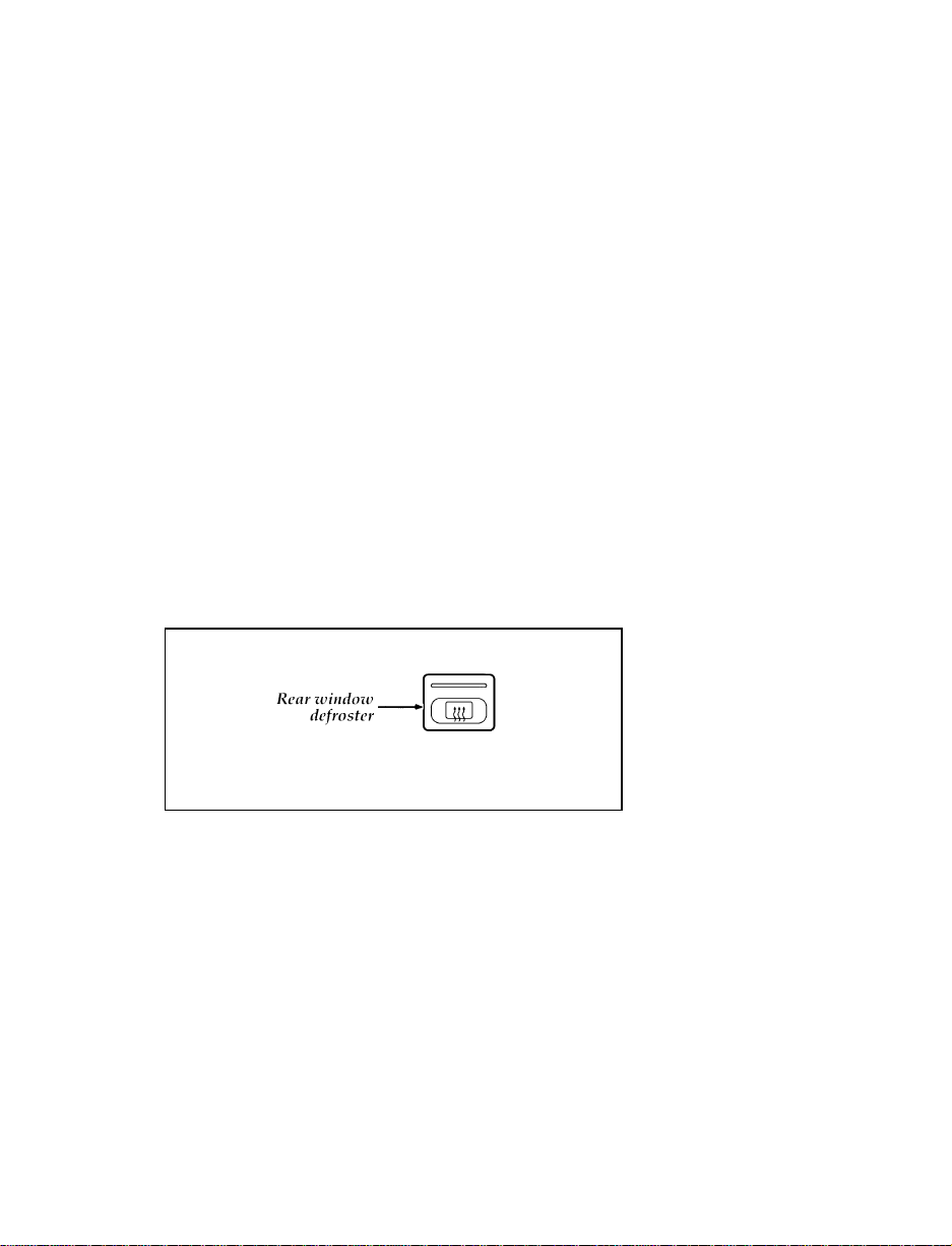
Rear Window Defroster (If equipped)
(Standard in Canada)
Rear window defroster button
The defroster for the rear window clears frost,
fog, or thin ice from both the inside and outside
of the rear window. The rear window defroster
button is located on the lower right of the
instrument panel below the climate control
panel. This button is also used to activate your
heated power mirrors (if equipped).
71
Page 73

To defrost the rear window:
1. Clear any snow from the rear window.
2. Get in your vehicle and start the engine.
3. Press the rear defrost button. The indicator
light turns on.
The defroster turns off automatically after 15 to
25 minutes. If the window is not clear, turn on
the defroster again. It will also automatically
shut off any time the engine is shut off.
NOTE: Never use sharp instruments or
window cleaners with abrasives to
clean the inside of your rear window.
If you do, you may damage the heating
elements that are bonded to the inside
of the rear window and cause damage
to the rear window defroster.
Lighting Up the Interior and Instrument
Panel
With the parking lamps or headlamps on, the
brightness of the instrument panel lighting can
be adjusted.
To brighten or dim the instrument panel
lighting, rotate the dimmer control thumbwheel
as desired.
Dimmer control thumbwheel
72
Page 74

The dimmer control thumbwheel is located to
the left of the steering wheel on the instrument
panel.
Dome Lamp
The dome lamp illuminates whenever one of the
front doors is opened and turns off
automatically when the doors are closed. You
may turn the dome lamp on and off while the
doors are closed by using the ON/OFF switch
located on the interior/map lamp control panel.
Interior/map lamp control panel
Map lamps (if equipped)
The map lamps can be turned on by using the
interior/map lamp control panel located between
the sun visors.
There are two map lamps, one for the driver
and one for the passenger. To turn on the map
lamp, push the button that is next to the lamp.
73
Page 75

Push the buttons again to turn the map lamps
off.
Cleaning the Interior Lamps
Your interior dome lamps and map lamps are
plastic and should be cleaned with a mild
detergent diluted in water. Rinse them with clear
water.
Fog Lamps (If equipped)
The fog lamps only operate when the headlamps
are on low beam. To activate fog lamps, push
the button on the control panel below the
climate controls. An indicator light on the button
will illuminate. Push the button again to turn
the fog lamps off.
74
Page 76

Fog lamp button
For information about the radio in your vehicle,
refer to the Ford Electronic Sound Systems
Operating Guide in this Owner Guide.
Radios
The electronic radios have a built-in clock. For
complete operating instructions, refer to the Ford
Electronic Sound Systems Operating Guide in this
owner guide.
Radio Antenna
The radio antenna is mounted on the rear
passenger side quarter panel of the vehicle. It is
a fixed mast antenna and cannot be retracted.
75
Page 77

Steering Column Controls
The controls on the steering column and wheel
are designed to give you easy access to the
controls while you are driving.
You can use the turn signal lever on the left side
of the steering column to:
operate the headlamps and parking lamps
❑
operate the turn signals and cornering lamps
❑
turn the high beams on/off
❑
flash the lamps
❑
Headlamps and Parking Lamps
To turn the parking lamps or headlamps on,
twist the knob at the end of the turn signal
lever.
FIRST STOP — Turning the knob to the first
stop (g) will turn on the the license plate
lamps, parking lamps, side marker lamps, tail
lamps and instrument panel lamps.
SECOND STOP — Turning the knob to the
second stop (B) will turn on the headlamps,
license plate lamps, parking lamps, side marker
lamps, tail lamps and instrument panel lamps.
77
Page 78

Headlamp control
Daytime Running Light System
(Canadian vehicles only)
In Canada, certain regulations require vehicles to
be driven with lights illuminated during daytime
operation. It is for that reason that the daytime
running lights are automatically illuminated
when the ignition switch is turned to the ON
position. The daytime running lights are
switched off under the following conditions:
when the headlamps are switched on
❑
when the parking brake is applied
❑
when the flash-to-pass system is used
❑
RWARNING
The Daytime Running Light (DRL) system
will not illuminate the tail lamps and
parking lamps. Turn on your headlamps
at dusk. Failure to do so may result in a
collision.
78
Page 79

Raising the Headlamps Manually
If the power headlamp door system becomes
inoperative, your vehicle has a manual retractor
system that allows you to raise the headlamps
manually (the headlamps will not turn on). The
retractors are located under the hood and behind
each headlamp. Remove the cap and turn the
knob. Each headlamp must be raised separately.
Before using the manual retractors to raise your
headlamps, the RETRA fuse must be removed.
Open the main fuse panel. Refer to the
underhood fuse panel in Servicing Your Probe
later in this owner guide. Pull the RETRA (20A)
fuse straight out.
Inspect the removed fuse. If it is blown, replace
it with a new one of the same rating. If it isn’t
blown or if a new fuse does not solve the
problem, remove it and operate the headlamp
manually.
RWARNING
Always remove the RETRA (20A) fuse
before manually operating a headlamp
retractor or attempting to remove anything
from the headlamp. Failure to remove the
RETRA fuse could cause injury to a hand
or fingers.
RWARNING
When reinstalling the RETRA fuse, make
sure nothing is near the headlamp
retractor. It may move suddenly while the
fuse is being inserted, causing injury to
hands and fingers.
79
Page 80

Manual headlamp retractors located behind the headlamps
High Beams and Flashing the Lamps
To turn on the high beams, turn the headlamp
control knob to the headlamp ON position and
push the turn signal lever away from you until
it latches. When the high beams are ON, the
high beam indicator light on the instrument
panel comes on.
To turn off the high beams, pull the lever
toward you until it latches. The high beam
indicator light turns off.
80
Page 81
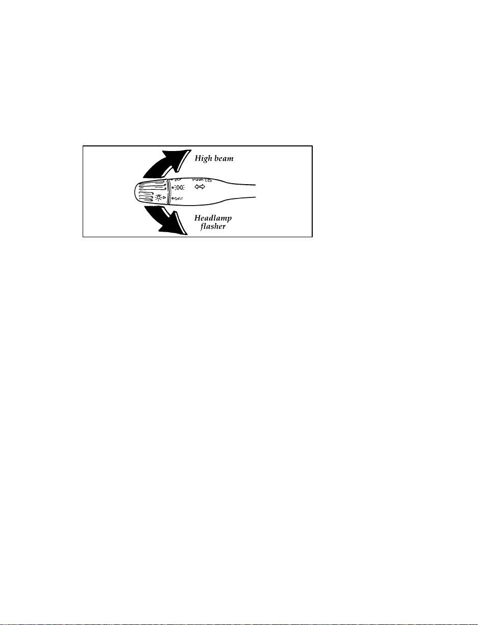
Flashing the Lights
To flash the headlamps, pull the lever toward
you for a moment and then release it. The
headlamps will flash whether the headlamp
knob is in the on or off position.
Highbeam and flash-to-pass operation
If the headlamps are retracted when you pull
the lever toward you, they will pop up and
flash.
Cleaning the Exterior Lamps
Do not use dry paper towel, chemical solvents
or abrasive cleaners to clean the lamps, as these
may cause scratches or crack the lamps.
To alert other drivers to hazardous situations,
press the flasher switch on the top of the
steering column. All the turn signals will flash
on and off at the same time. The flashers will
also operate while the brake pedal is applied. To
turn the hazards off, press the switch again.
The flashers work whether your vehicle is
running or not. The flashers will work for up to
two hours when the battery is fully charged and
in good condition. They will not drain the
battery excessively unless they are left on for an
extended period of time.
81
Page 82

If the flashers run for longer than 2 hours while
your engine is not running, or if your battery is
not fully charged, your battery could be drained.
Hazard warning flasher switch
82
Page 83

Turn Signals
Move the lever up to signal a right turn. Move
it down to signal a left turn. The corresponding
indicator light in the instrument cluster will
flash.
If the turn signal stays on after you turn, move
the lever back to the center (OFF) position.
For lane changes, move the lever far enough to
signal but not to latch. The lever will return to
the off position when you release it.
Turn signal
83
Page 84

To operate the windshield wipers and washers,
make sure your ignition key is turned to the ON
position.
The windshield wipers have two speeds. To
operate the wipers, pull down the lever on the
right side of your steering column. The first
position is LO (Low) and the second position is
HI (High). To turn the wipers off, return the
lever to the uppermost position.
Windshield wiper control
ONE-TOUCH WIPER CONTROL (If equipped)
— For one wiping cycle, push the lever away
from you and release it with the lever in the
OFF or interval position. The ignition switch
must be in the ON position for this operation.
One touch wiper control
84
Page 85

Interval Wipers (If equipped)
In addition to two speed wipers, your vehicle
may have wipers that you can set to operate at
varying intervals. For example, you can set the
interval so they wipe less often when it drizzles
and more often in heavier rain.
Variable interval wiper control
To set the interval wipers, pull the lever down
to the first position. Turn the ring on the lever
to the frequency of wiper operation you desire.
Windshield Washer
To clean the windshield, pull the wiper lever
toward you. Washer fluid sprays until the lever
is released.
Windshield washer/control
85
Page 86

If the washer does not work, check the washer
fluid level visually and fill if needed. See
Servicing Your Probe later in this owner guide. If
there is fluid in the reservoir, and your washer
doesn’t work, consult your Ford or
Lincoln-Mercury dealer.
Do not try to clean the windshield when the
washer fluid container is empty or activate the
washers at any time for more than 15 seconds
continuously. This could damage the washer
pump system.
RWARNING
In freezing weather, the washer solution
may freeze on the windshield and obscure
your vision. Always warm up the
windshield with the defroster before you
use the washer fluid. If you cannot see
through the windshield clearly, it can
increase the risk of being involved in a
collision.
86
Page 87

To sound the horn, push the horn button on
either side of the steering wheel. Check the horn
regularly to be sure it operates properly.
Using the horn
87
Page 88

(If equipped)
RWARNING
Never adjust the steering column/wheel
when the vehicle is moving. You could
lose control of the vehicle and injure
someone.
To change the position of the steering
column/wheel, pull the release lever on the
column toward you. Tip the steering wheel to
the desired position. Release the lever to lock the
steering wheel in place.
Tilt steering column
88
Page 89
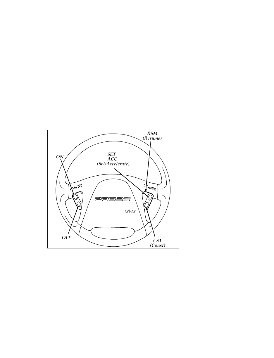
If your vehicle has speed control, you can
automatically maintain a constant speed at or
above 30 mph (50 km/h).
Use of radio transmitting equipment that is not
Federal Communications Commission (FCC) or
in Canada the Canadian Radio and
Telecommunications Commission (CRTC)
approved may cause the speed control to
malfunction. Therefore, use only properly
installed FCC (CRTC in Canada) approved radio
transmitting equipment in your vehicle.
Speed control switches on the steering wheel
To set the speed control:
1. Press the ON switch and release it
immediately.
2. Accelerate to the desired speed above
30 mph (50 km/h) using the accelerator
pedal.
89
Page 90

3. Press SET ACC and release it immediately to
set your speed. If you keep this button
depressed, your speed will continue to
increase.
4. Take your foot off the accelerator pedal.
Your vehicle will maintain the speed you set.
If you drive up or down a steep hill, your
vehicle may momentarily slow down or speed
up, even though the speed control is on. This is
normal.
NOTE: If your vehicle is equipped with an
automatic transaxle, and if your speed
increases above your set speed while
driving in Overdrive on a downhill
grade, you may want to turn the
Overdrive off and use Drive. You may
turn the Overdrive off by pressing the
Overdrive off (O/D OFF) button. This
will reduce vehicle speed. Speed
control cannot reduce the vehicle speed
if it goes above your set speed on a
downhill grade.
NOTE: If your vehicle is equipped with a
5-speed manual transaxle, and if your
speed increases above your set speed
while driving in 5 (Fifth) gear on a
downhill grade, you may want to shift
to 4 (Fourth) gear to reduce vehicle
speed. Depressing the clutch pedal
cancels speed control, therefore speed
control must be reset by pressing the
SET ACC or RSM switches. Speed
control cannot reduce the vehicle speed
if it goes above your set speed on a
downhill grade.
90
Page 91

RWARNING
Do not use the speed control in heavy
traffic or on roads that are winding,
slippery, or unpaved.
Accelerating With the Speed Control
Operating
If you want to speed up momentarily or regain
preset speed on hills when the speed control is
operating, simply accelerate using the accelerator
pedal. Manually accelerating to a higher speed
does not interfere with the speed control; when
you take your foot off the accelerator, the
vehicle returns to the set speed.
You can also speed up by pressing the SET ACC
button. Release the button when the vehicle has
accelerated to the desired speed.
NOTE: If your vehicle has a 5-speed manual
transaxle, you may want to drive in 4
(Fourth) gear in mountainous areas or
at high altitudes to improve speed
control performance.
NOTE: When driving uphill, especially with a
heavy load, significant speed drops
may occur. If the speed drops more
than 8 to 14 mph (15-25 km/h) the
automatic speed control will, by
design, be cancelled. You may need to
control your speed manually while
driving up steep grades in order to
maintain the selected speed.
91
Page 92

NOTE: If your vehicle has an automatic
overdrive transaxle, you may want to
drive with the Overdrive off when
driving in hilly terrain or at high
altitudes. You may turn the Overdrive
off and use Drive by pressing the
Overdrive off (O/D OFF) button. This
will improve speed control
performance.
Resetting the Speed Control
To reset the speed control to a lower speed,
press and hold the CST switch. Let your vehicle
slow down to the desired speed and release the
CST switch.
If you have a 2.0L automatic transaxle vehicle
you may reset the vehicle speed control to a
lower speed by pushing, and then quickly
releasing, the CST switch. Each time you do this,
the set speed will decrease by 1 mph
(1.6 km/h). See Tap Up and Tap Down in this
chapter.
To reset the speed control to a higher speed, you
can follow one of these procedures:
Accelerate to the desired speed using the
❑
accelerator pedal, then press the SET ACC
switch and release it immediately.
Press and hold the SET ACC switch until the
❑
vehicle accelerates to the desired speed, then
release the switch.
Push, and then quickly release, the SET ACC
❑
switch. Each time you do this, the set speed
will increase by 1 mph (1.6 km/h). (NOTE:
This feature is only available on 2.0L
automatic transaxle vehicles.) See Tap Up and
Tap Down in this chapter.
92
Page 93

To Cancel Speed Control
You can cancel the speed control while you are
driving.
Press the brake pedal or clutch pedal (manual
transaxle) slightly. The speed control is
cancelled, but you can reset it by pressing SET
ACC or RSM.
To Turn Off the Speed Control System
Press the OFF switch. The speed control system
is off and will remain off until you press the ON
switch and reset the speed control.
In addition, the speed control is turned off each
time you turn the vehicle off.
Cancelling and Resuming a Set Speed
If you press the brake pedal, the clutch pedal
(manual transaxle), or shift the transaxle into N
(Neutral) the speed control is suspended. You
can return to the speed you set by using the
RSM switch.
To resume the speed you had before, you must
be driving at least 30 mph (50 km/h).
Press and release the RSM switch. Your vehicle
gradually returns to the previously set speed
and then maintains it.
93
Page 94

Tap Up and Tap Down (2.0L vehicles with
automatic transaxle only)
Tap Up and Tap Down is a new feature which,
like SET ACC and CST, can be used to either
increase or decrease the set speed. Speed
changes are made in 1 mph (1.6 km/h)
increments. Once the speed has been set by
pressing the ON and the SET ACC switches, the
set speed may be increased by 1 mph
(1.6 km/h) by a momentary tap of the SET ACC
button. The set speed can be reduced by 1 mph
(1.6 km/h) by a momentary tap of the CST
button. Multiple taps will cause the set speed to
increase or decrease in increments of 1 mph
(1.6 km/h). For example, if the current set speed
is 60 mph (100 km/h) five taps of the ACC
switch will increase the vehicle speed and SET it
at 65 mph (105 km/h).
94
Page 95

Features
Your vehicle has a variety of features designed
for your comfort, convenience and safety. Read
this chapter to find out about standard and
optional features.
The outside of the door
The inside of the door
If you close the door with the lock button
depressed, the door will remain locked.
95
Page 96

Power Door Locks (If equipped)
If your vehicle has power door locks, the
controls to lock the doors are below the inside
door handles on each door. When you close the
doors after you set the door locks, the doors
remain locked. If the power mechanism ever
fails, the manual door locks will override the
power controls.
NOTE: Vehicles equipped with power locks
have a safety feature which allows you
to unlock one or both front doors from
either door key lock cylinder. To
unlock the driver’s or passenger door
only, insert the key in the door lock
cylinder and turn to the left
(counterclockwise) to the first position.
To unlock the other door at the same
time, simply continue turning the key
to the left to the second position. Both
doors are locked by turning the key to
the right (clockwise).
96
Page 97

Power locks on the driver’s door
Remote Keyless Entry System
(If equipped)
Your vehicle may be equipped with a remote
keyless entry system. This option will allow you
to open your vehicle using a remote transmitter
from distances of up to 33 feet (10 meters) away.
The remote feature will operate only when the
ignition is in the OFF position.
The transmitter can unlock the driver’s door,
unlock all doors, lock all doors, or activate the
vehicle’s horn and hazard warning lamps for the
panic alarm feature.
By pressing the UNLOCK button on the
transmitter once, you can unlock the driver side
door. Pressing the UNLOCK button a second
time within five seconds of unlocking the
driver’s door will unlock the other doors.
97
Page 98

You can lock all your vehicle doors by pressing
the LOCK button. If you press the LOCK button
a second time within five (5) seconds, the horn
will sound briefly to verify that the doors have
been locked.
When the PANIC button is pressed, the horn
will sound and the hazard warning lamps will
flash. This will continue for up to approximately
two minutes and 45 seconds unless it is turned
off by pressing the PANIC button a second time.
The panic mode can also be cancelled by turning
the ignition key to ON or ACC.
Up to four transmitters can be programmed for
your vehicle. Your vehicle comes with two
transmitters. Additional transmitters can be
ordered from your dealer.
Remote keyless entry transmitter
The remote keyless entry system is equipped
with an illuminated entry system. This system is
activated by opening the door.
When the system is activated, the dome lamp
will illuminate, and will stay lit for
approximately 25 seconds. The dome lamp will
shut off when the doors are closed.
98
Page 99

Replacing the batteries
The remote entry transmitter is powered by two
coin type three-volt lithium 1616
batteries (included) that should last for several
years of normal use. If you notice a significant
decrease in operating range, the batteries should
be replaced. Replacement batteries can be
purchased at most pharmacies, watch stores or
at your Ford or Lincoln-Mercury dealer.
NOTE: The operating range of the remote
entry system can also be affected by
weather conditions (such as very cold
temperatures) or structures around the
vehicle (buildings, other vehicles, radio
and TV towers, etc.). Typical operating
range will allow you to be up to 33
feet (10 meters) away from your
vehicle.
Opening the remote transmitter
99
Page 100

The transmitter can be snapped apart to replace
the batteries by twisting a thin coin between the
two halves of the transmitter. DO NOT TAKE
THE FRONT PART OF THE TRANSMITTER
APART. Carefully remove the old batteries.
When installing the new batteries, be sure to
place the positive (+) side down as marked.
Snap the two halves back together.
Replacement/additional transmitters
In the event a transmitter is lost, return the
remaining transmitter(s) to your dealer for
reprogramming of your remote entry system.
This is necessary to prevent unauthorized use of
the lost transmitter.
Additional transmitters may be purchased from
your dealer (remote entry system will work with
up to four transmitters). Follow the same
programming procedure as above.
All transmitters must be programmed (or
reprogrammed) at the same time. If the
programming mode is entered and the
transmitters are not programmed (or
reprogrammed) at the same time, they will not
operate with the system.
100
 Loading...