

Page 1

Table of contents
Introduction 2
Instrumentation 6
Controls and features 13
Starting 18
Driving 23
Roadside emergencies 34
Maintenance and care 52
Capacities and specifications 80
Reporting Safety Defects 80
Index 84
All rights reserved. Reproduction by any means, electronic or mechanical
including photocopying, recording or by any information storage and retrieval
system or translation in whole or part is not permitted without written
authorization from Ford Motor Company. Ford may change the contents without
notice and without incurring obligation.
Copyright © 2000 Ford Motor Company
1
Page 2
Introduction
The following warning may be required by California law:
CALIFORNIA Proposition 65 Warning
WARNING: Engine exhaust, some of its constituents, and
certain vehicle components contain or emit chemicals known to
the State of California to cause cancer and birth defects or other
reproductive harm. In addition, certain fluids contained in vehicles and
certain products of component wear contain or emit chemicals known
to the State of California to cause cancer and birth defects or other
reproductive harm.
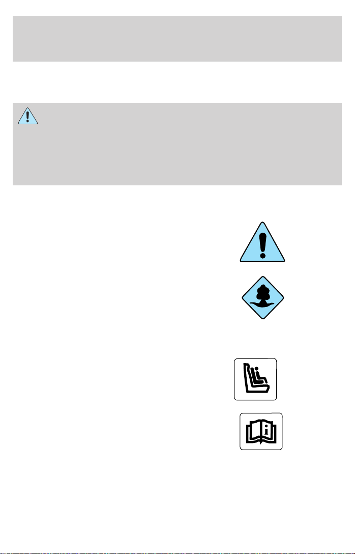
ICONS
Indicates a safety alert. Read the
following section on Warnings.
Indicates vehicle information related
to recycling and other
environmental concerns will follow.
Correct vehicle usage and the
authorized disposal of waste
cleaning and lubrication materials are significant steps towards
protecting the environment.
Indicates a message regarding child
safety restraints. Refer to Seating
and safety restraints for more
information.
Indicates that this Owner Guide
contains information on this subject.
Please refer to the Index to locate
the appropriate section which will
provide you more information.
2
Page 3

Introduction
WARNINGS
Warnings provide information which may reduce the risk of personal
injury and prevent possible damage to others, your vehicle and its
equipment.
BREAKING-IN YOUR VEHICLE
There are no particular breaking-in rules for your vehicle. During the
first 1 600 km (1 000 miles) of driving, vary speeds frequently. This is
necessary to give the moving parts a chance to break in.
INFORMATION ABOUT THIS GUIDE
The information found in this guide was in effect at the time of printing.
Ford may change the contents without notice and without incurring
obligation.
SPECIAL NOTICES
Notice to owners of pickup trucks and utility type vehicles
Utility vehicles have a significantly higher rollover rate than
other types of vehicles.
Before you drive your vehicle, please read this Owner’s Guide carefully.
Your vehicle is not a passenger car. As with other vehicles of this type,
failure to operate this vehicle correctly may result in loss of control or an
accident.
Be sure to read Driving off road in the Driving chapter as well as the
“Four Wheeling” supplement included with 4WD and utility type vehicles.
3
Page 4
Introduction
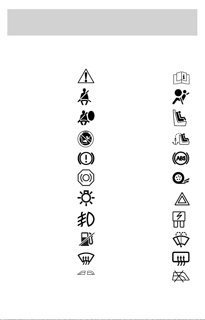
These are some of the symbols you may see on your vehicle.
Vehicle Symbol Glossary
Safety Alert
Fasten Safety Belt Air Bag-Front
Air Bag-Side Child Seat
Child Seat Installation
Warning
Brake System Anti-Lock Brake System
Brake Fluid Non-Petroleum Based
Master Lighting Switch Hazard Warning Flasher
Fog Lamps-Front Fuse Compartment
Fuel Pump Reset Windshield Wash/Wipe
See Owner’s Guide
Child Seat Tether
Anchorage
Traction Control
Windshield
Defrost/Demist
Power Windows
Front/Rear
4
Rear Window
Defrost/Demist
Power Window Lockout
Page 5
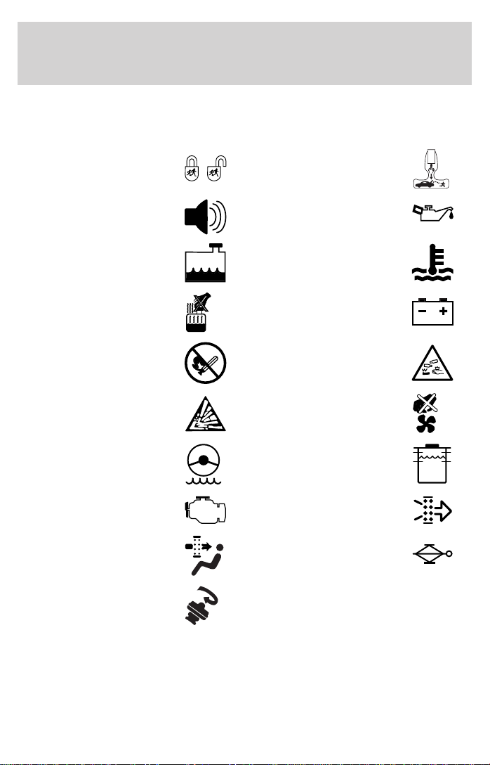
Vehicle Symbol Glossary
MAX
MIN
Introduction
Child Safety Door
Lock/Unlock
Interior Luggage
Compartment Release
Symbol
Panic Alarm Engine Oil
Engine Coolant
Engine Coolant
Temperature
Do Not Open When Hot Battery
Avoid Smoking, Flames,
or Sparks
Battery Acid
Explosive Gas Fan Warning
Power Steering Fluid
Maintain Correct Fluid
Level
Emission System Engine Air Filter
Passenger Compartment
Air Filter
Jack
Check fuel cap
5
Page 6
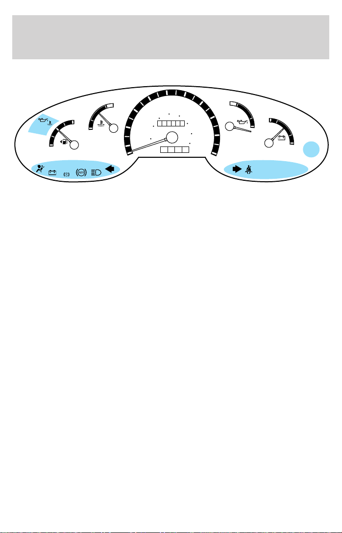
Instrumentation
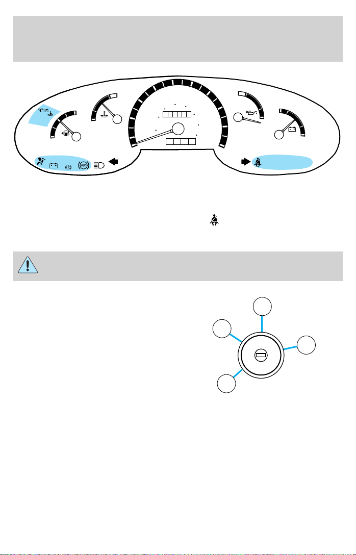
WARNING LIGHTS AND CHIMES
50
80
60
000000
0000
60
100
90
H
18
L
8
O/D
OFF
SERVICE
ENGINE SOON
70
120
80
140
160
10 0
SERVICE
ENGINE
SOON
20
10
40
30
40
20 km/h
MPH
0
E
BRAKE
H
F
C
Service engine soon
Your vehicle is equipped with a
computer that monitors the engine’s
emission control system. This
system is commonly known as the
On Board Diagnostics System (OBD
II). The OBD II system protects the
environment by ensuring that your vehicle continues to meet
government emission standards. The OBD II system also assists the
service technician in properly servicing your vehicle.
The Service Engine Soon indicator light illuminates when the ignition is
first turned to the ON position to check the bulb. If it comes on after the
engine is started, one of the engine’s emission control systems may be
malfunctioning. The light may illuminate without a driveability concern
being noted. The vehicle will usually be drivable and will not require
towing.
What you should do if the Service Engine Soon light illuminates
Light turns on solid:
This means that the OBD II system has detected a malfunction.
Temporary malfunctions may cause your Service Engine Soon light to
illuminate. Examples are:
1. The vehicle has run out of fuel. (The engine may misfire or run
poorly.)
2. Poor fuel quality or water in the fuel.
3. The fuel cap may not have been properly installed and securely
tightened.
6
Page 7
Instrumentation
These temporary malfunctions can be corrected by filling the fuel tank
with high quality fuel of the recommended octane and/or properly
installing and securely tightening the gas cap. After three driving cycles
without these or any other temporary malfunctions present, the Service
Engine Soon light should turn off. (A driving cycle consists of a cold
engine startup followed by mixed city/highway driving.) No additional
vehicle service is required.
If the Service Engine Soon light remains on, have your vehicle serviced
at the first available opportunity.
Light is blinking:
Engine misfire is occurring which could damage your catalytic converter.
You should drive in a moderate fashion (avoid heavy acceleration and
deceleration) and have your vehicle serviced at the first available
opportunity.
Under engine misfire conditions, excessive exhaust temperatures
could damage the catalytic converter, the fuel system, interior
floor coverings or other vehicle components, possibly causing a fire.
Safety belt
Momentarily illuminates when the
ignition is turned to the ON position
to remind you to fasten your safety
belts. For more information, refer to
the Seating and safety restraints
chapter.
Brake system warning
Momentarily illuminates when the
ignition is turned to the ON position
to ensure the circuit is functional.
Also illuminates if the parking brake
is engaged. If the brake warning
lamp does not illuminate at these times, seek service immediately.
Illumination after releasing the parking brake indicates low brake fluid
level and the brake system should be inspected immediately.
BRAKE
!
7
Page 8

Instrumentation
Anti-lock brake system (ABS) (If equipped)
Momentarily illuminates when the
ignition is turned to the ON position
to ensure the circuit is functional. If
the light stays on, the ABS needs to
be serviced. With the ABS light on,
the anti-lock brake system is disabled and normal braking is still effective
unless the brake warning light also remains illuminated with the parking
brake released.
O/D off (if equipped)
Illuminates when the Transmission
Control Switch (TCS), refer to
Overdrive control in the Controls
and Features chapter, has been
pushed turning the transmission overdrive function OFF. When the light
is on, the transmission does not operate in the overdrive mode, refer to
the Driving chapter for transmission function and operation.
The light may also flash steadily if a transmission malfunction is
detected. If the light does not come on when the Transmission Control
Switch is depressed or if the light flashes steadily, have your vehicle
serviced as soon as possible, damage to the transmission could occur.
Turn signal
Illuminates when the left or right
turn signal or the hazard lights are
turned on. If one or both of the
indicators stay on continuously,
check for a burned-out turn signal
bulb. Refer to Bulbs in the Maintenance and care chapter.
ABS
O/D
OFF
High beams
Illuminates when the high beam
headlamps are turned on.
8
Page 9
Instrumentation
Charging system
Illuminates when the ignition is
turned to the ON position and the
engine is off. The light also
illuminates when the battery is not
charging properly, requiring
electrical system service.
Safety belt warning chime
Sounds to remind you to fasten your safety belts.
For information on the safety belt warning chime, refer to the Seating
and safety restraints chapter.
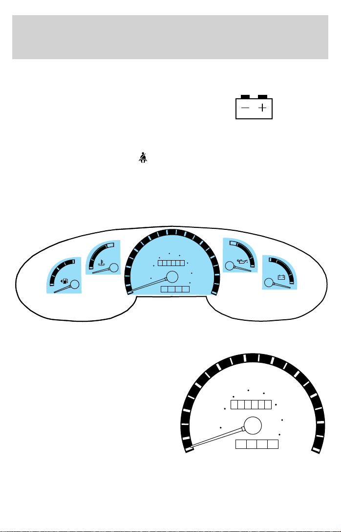
GAUGES
50
80
60
000000
0000
60
100
90
H
18
L
8
70
120
80
140
160
10 0
20
10
40
30
40
20 km/h
MPH
0
H
F
C
E
Speedometer
Indicates the current vehicle speed.
20
10
0
30
40
60
000000
40
20 km/h
MPH
50
60
80
0000
100
70
120
140
160
80
90
10 0
9
Page 10
Instrumentation
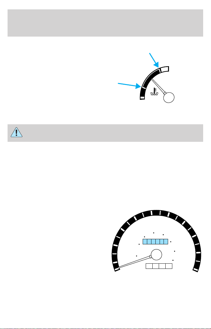
Engine coolant temperature gauge
Indicates the temperature of the
engine coolant. At normal operating
temperature, the needle remains
within the normal area (the area
between the “H” and “C”). If it
enters the red section, the engine is
overheating. Stop the vehicle as
soon as safely possible, switch off
C
the engine immediately and let the
engine cool. Refer to Engine coolant in the Maintenance and care
chapter.
Never remove the coolant reservoir cap while the engine is
running or hot.
This gauge indicates the temperature of the engine coolant, not the
coolant level. If the coolant is not at its proper level the gauge indication
will not be accurate. If the gauge enters the red section, the oil
pressure/engine coolant and Check Engine/Service Engine Soon
indicators illuminate, refer to What you should know about fail-safe
cooling in the Maintenance and care chapter.
Odometer
Registers the total kilometers
(miles) of the vehicle.
40
60
30
000000
40
20
20 km/h
10
MPH
0
H
50
60
80
0000
100
70
120
140
160
80
90
10 0
10
Page 11
Trip odometer
Registers the kilometers (miles) of
individual journeys. To reset,
depress the control.
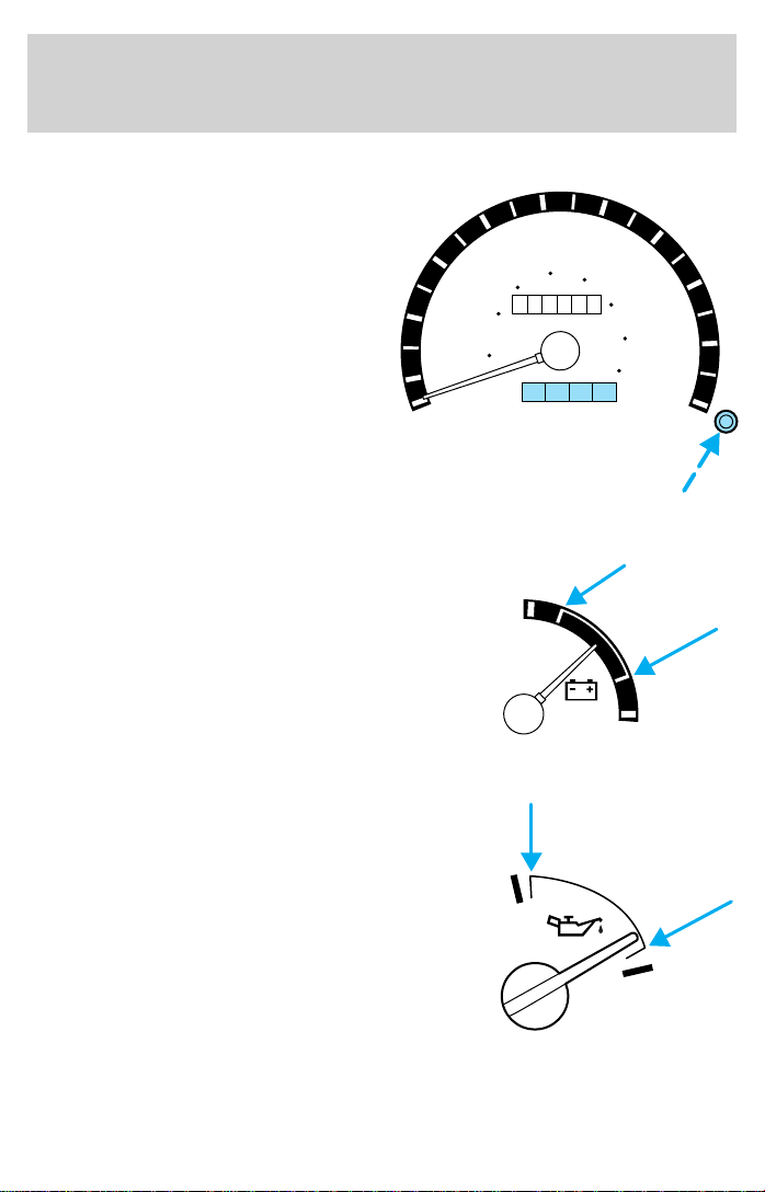
Battery voltage gauge
This shows the battery voltage when
the ignition is in the ON position. If
the pointer moves and stays outside
the normal operating range (as
indicated by arrows), have the
vehicle’s electrical system checked
as soon as possible.
20
10
0
Instrumentation
50
60
80
100
000000
0000
30
40
60
40
20 km/h
MPH
18
8
120
70
80
140
90
160
10 0
Engine oil pressure gauge
This shows the engine oil pressure
in the system. Sufficient pressure
exists as long as the needle remains
in the normal range (the area
between the “L” and “H”).
If the gauge indicates low pressure,
H
stop the vehicle as soon as safely
possible and switch off the engine
L
immediately. Check the oil level.
Add oil if needed (refer to Engine
oil in the Maintenance and care
chapter). If the oil level is correct, have your vehicle checked at your
dealership or by a qualified technician.
11
Page 12
Instrumentation
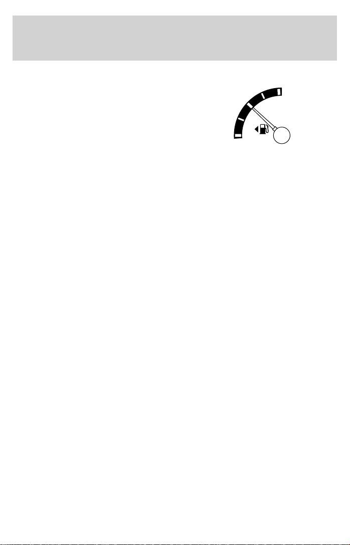
Fuel gauge
Displays approximately how much
fuel is in the fuel tank (when the
key is in the ON position). The fuel
gauge may vary slightly when the
vehicle is in motion or after
refueling. The ignition should be in
the OFF position while the vehicle is
being refueled. When the gauge first indicates empty, there is a small
amount of reserve fuel in the tank. When refueling the vehicle from an
empty indication, the amount of fuel that can be added will be less than
the advertised capacity due to the reserve fuel.
E
F
12
Page 13
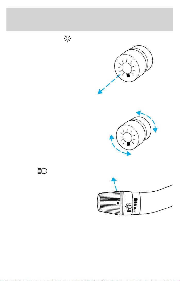
HEADLAMP CONTROL
• Pull the headlamp control toward
you to the first position to turn
on the parking lamps, tail lamps,
license plate lamps and marker
lamps.
• Pull the headlamp control toward
you to the outer position to turn
on the headlamps (in addition to
the previous lamps).
PANEL DIMMER CONTROL
To adjust the brightness of the
instrument panel:
• Rotate
clockwise/counterclockwise when
the headlamp control is in the
parking lamp or low-beam
position.
To turn on the courtesy lamp:
• Rotate fully counterclockwise.
High beams
Push forward to activate.
Pull toward you to deactivate.
Controls and features
HI
LO
F
S
OFF
13
Page 14
Controls and features
Flash to pass
Pull toward you to activate and
release to deactivate.
POSITIONS OF THE IGNITION
1. LOCK, locks the steering wheel,
gearshift lever (automatic transaxle
only) and allows key removal. On
vehicles with a manual transaxle
2
push the key in while turning to
lock.
2. ACCESSORY, allows the electrical
accessories such as the radio to
operate while the engine is not
1
running.
3. ON, all electrical circuits operational. Warning lights illuminated. Key
position when driving.
4. START, cranks the engine. Release the key as soon as the engine
starts.
HI
LO
F
S
OFF
3
N
O
S
I
I
C
T
C
A
I
I
A
I
I
K
0
C
O
L
4
R
T
14
Page 15
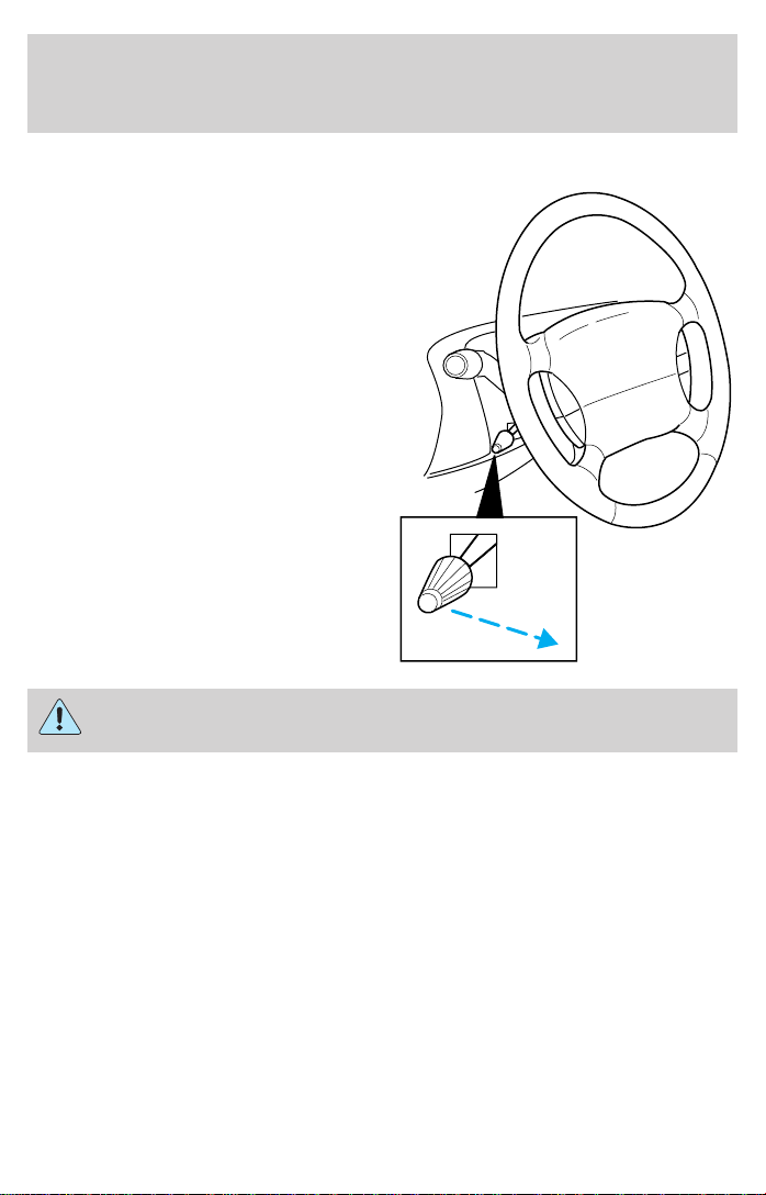
TILT STEERING WHEEL
Pull the tilt steering control toward
you to move the steering wheel up
or down. Hold the control while
adjusting the wheel to the desired
position, then release the control to
lock the steering wheel in position.
Never adjust the steering wheel when the vehicle is moving.
Controls and features
15
Page 16
Controls and features
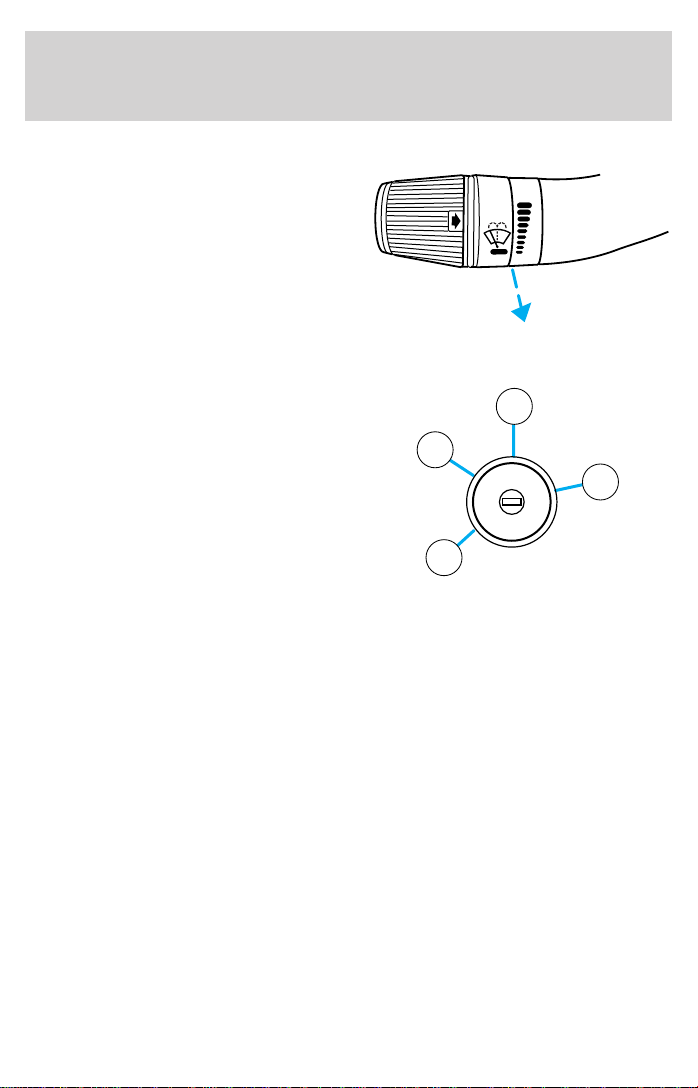
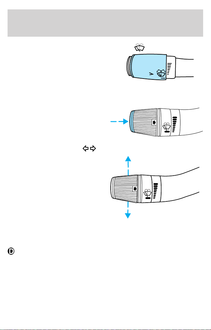
WINDSHIELD WIPER/WASHER CONTROLS
HI
LO
Rotate the windshield wiper control
to the desired interval, low or high
speed position.
The bars of varying length are for intermittent wipers. When in this
position rotate the control upward for fast intervals and downward for
slow intervals.
Push the control on the end of the
stalk to activate washer. Push and
hold for a longer wash cycle. The
washer will automatically shut off
after ten seconds of continuous use.
TURN SIGNAL CONTROL
• Push down to activate the left
turn signal.
• Push up to activate the right turn
signal.
HI
LO
OFF
F
S
OFF
HI
LO
F
S
OFF
F
S
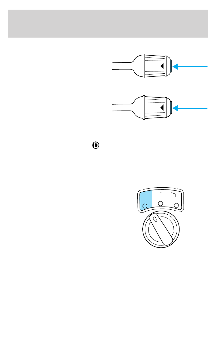
OVERDRIVE CONTROL
Activating overdrive
(Overdrive) is the normal drive position for the best fuel economy.
The overdrive function allows automatic upshifts and downshifts through
all available gears.
16
Page 17
Controls and features
Deactivating overdrive
Press the Transmission Control
Switch (TCS) located on the end of
the gearshift lever. The
Transmission Control Indicator Light
(TCIL) will illuminate on the
instrument cluster.
The transmission will operate in all
gears except overdrive. To return to
normal overdrive mode, press the
Transmission Control Switch again.
The TCIL will no longer be
illuminated.
When you shut off and re-start your vehicle, the transmission will
automatically return to normal
(Overdrive) mode.
For additional information about the gearshift lever and the transmission
control switch operation refer to the Automatic Transmission
Operation section of the Driving chapter.
4WD CONTROL (IF EQUIPPED)
This control operates the 4WD.
Refer to the Driving chapter for
more information.
ON/OFF
ON/OFF
4x2
O/D
O/D
HIGH
4x4
LOW
17
Page 18
Starting
PREPARING TO START YOUR VEHICLE
Engine starting is controlled by the powertrain control system. This
system meets all Canadian Interference-Causing Equipment standard
requirements regulating the impulse electrical field strength of radio
noise.
When starting a fuel-injected engine, avoid pressing the accelerator
before or during starting. Only use the accelerator when you have
difficulty starting the engine. For more information on starting the
vehicle, refer to Starting the engine in this chapter.
Extended idling at high engine speeds can produce very high
temperatures in the engine and exhaust system, creating the risk
of fire or other damage.
Do not park, idle, or drive your vehicle in dry grass or other dry
ground cover. The emission system heats up the engine
compartment and exhaust system, which can start a fire.
Do not start your vehicle in a closed garage or in other enclosed
areas. Exhaust fumes can be toxic. Always open the garage door
before you start the engine. See Guarding against exhaust fumes in
this chapter for more instructions.
If you smell exhaust fumes inside your vehicle, have your dealer
inspect your vehicle immediately. Do not drive if you smell
exhaust fumes.
18
Page 19
Starting
Important safety precautions
A computer system controls the engine’s idle revolutions per minute
(RPM). When the engine starts, the idle RPM runs faster to warm the
engine. If the engine idle speed does not slow down automatically, have
the vehicle checked.
Before starting the vehicle:
1. Make sure all vehicle occupants have buckled their safety belts. For
more information on safety belts and their proper usage, refer to the
Seating and safety restraints chapter.
2. Make sure the vehicle accessories are off.
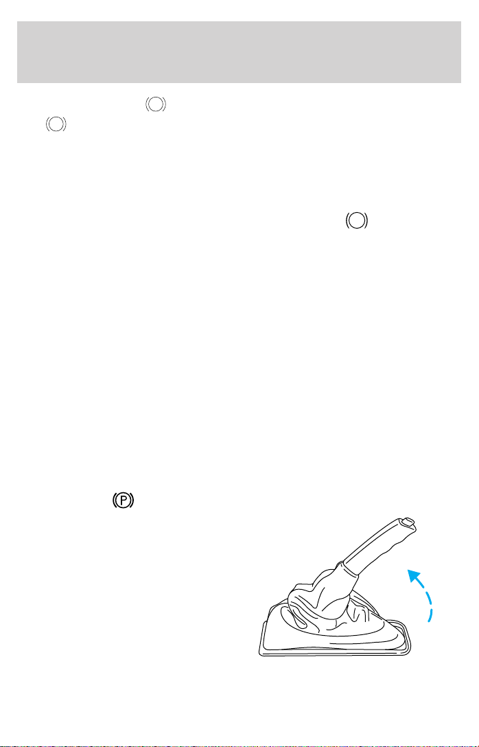
• Make sure the parking brake is
set.
• Make sure the gearshift is in P
(Park).
3. Turn the key to 4 (ON) without
turning the key to 5 (START).
If there is difficulty in turning the
key, firmly rotate the steering wheel
left and right until the key turns
freely. This condition may occur
when:
• front wheels are turned
• front wheel is against the curb
• steering wheel is turned when getting in or out of the vehicle
3
2
1
4
5
19
Page 20
Starting
50
80
60
000000
0000
60
100
90
H
18
L
8
SERVICE
ENGINE SOON
70
120
80
140
160
10 0
20
10
40
30
40
20 km/h
MPH
0
E
BRAKE
H
F
C
Make sure the corresponding lights illuminate briefly. If a light fails to
illuminate, have the vehicle serviced.
• If the driver’s safety belt is fastened, the light may not illuminate.
STARTING THE ENGINE
Whenever you start your vehicle, release the key as soon as the
engine starts. Excessive cranking could damage the starter.
1. Turn the key to 4 (START)
without pressing the accelerator
pedal and release as soon as the
engine starts. The key will return to
3 (ON).
2. If the temperature is above –12°
C (10° F) and the engine does not
start within five seconds on the first
try, turn the key to OFF, wait 10
2
1
3
N
O
S
I
I
C
T
C
A
I
I
A
I
I
K
0
C
O
L
4
R
T
seconds and try again.
3. If the temperature is below -12° C (10° F) and the engine does not
start in 15 seconds on the first try, turn the key OFF and wait 10
seconds and try again. If the engine does not start in two attempts, Press
the accelerator pedal all the way to floor and hold. Turn the key to
START position.
4. When the engine starts, release the key, then release the accelerator
pedal gradually as the engine speeds up.
5. After idling for a few seconds, apply the brake and release the parking
brake.
20
Page 21

Starting
Cold weather starting
Your flexible fuel vehicle is equipped with an engine block heater. The
standard 110V AC (male) plug is located at the front of the vehicle in
the upper left-hand air inlet opening, under the bumper.
When the temperature is expected to be –12°C (10°F) below and your
vehicle has fuel ethanol (E
engine block heater to ensure a quick start.
If temperatures are expected to remain below –12°C (10°F), it is
recommended that you reduce the alcohol content in your fuel tank to
about 70% by adding unleaded gasoline if your tank is not already full.
Thirteen liters (3 gallons) of gasoline will reduce the alcohol in 3/4 full
tank from 85% to about 70%. In some areas, winter blends of E85 will
already contain the extra gasoline. See the Refueling section of this
supplement for more information on alcohol fuels.
If you should unexpectedly have 85% alcohol in your fuel tank in
extremely cold temperatures with no way to use the engine block heater,
the engine may require extended crank times and several attempts to
start.
If the engine fails to start using the preceding instructions
1. Press the accelerator pedal 1/3 to 1/2 of the way to floor and hold.
2. Turn the key to START position.
3. When the engine starts, release the key, then release the accelerator
pedal gradually as the engine speeds up.
4. If the engine still fails to start, repeat steps one through three.
5. After the engine starts, hold your foot on the brake pedal, put the
gearshift lever in gear and release the parking brake. Slowly release the
brake pedal and drive away in a normal manner.
85) in the fuel tank, you should plug in the
d
Guarding against exhaust fumes
Although odorless and colorless, carbon monoxide is present in exhaust
fumes. Take precautions to avoid its dangerous effects.
If you ever smell exhaust fumes of any kind inside your vehicle,
have your dealer inspect and fix your vehicle immediately. Do
not drive if you smell exhaust fumes. These fumes are harmful and
could kill you.
21
Page 22

Starting
Have the exhaust and body ventilation systems checked whenever:
• the vehicle is raised for service.
• the sound of the exhaust system changes.
• the vehicle has been damaged in a collision.
WARNING: Engine exhaust, some of its constituents, and
certain vehicle components contain or emit chemicals known to
the State of California to cause cancer and birth defects or other
reproductive harm. In addition, certain fluids contained in vehicles and
certain products of component wear contain or emit chemicals known
to the State of California to cause cancer and birth defects or other
reproductive harm.
Important ventilating information
If the engine is idling while the vehicle is stopped in an open area for
long periods of time, open the windows at least 2.5 cm (one inch).
Adjust the heating or air conditioning (if equipped) to bring in fresh air.
Improve vehicle ventilation by keeping all air inlet vents clear of snow,
leaves and other debris.
22
Page 23

Driving
BRAKES
Your service brakes are self-adjusting. Refer to the scheduled
maintenance guide for scheduled maintenance.
Occasional brake noise is normal and often does not indicate a
performance concern with the vehicle’s brake system. In normal
operation, automotive brake systems may emit occasional or intermittent
squeal or groan noises when the brakes are applied. Such noises are
usually heard during the first few brake applications in the morning;
however, they may be heard at any time while braking and can be
aggravated by environmental conditions such as cold, heat, moisture,
road dust, salt or mud. If a “metal-to-metal,” “continuous grinding” or
“continuous squeal” sound is present while braking, the brake linings
may be worn-out and should be inspected by a qualified service
technician.
Four-wheel anti-lock brake system (ABS)
This vehicle is equipped with an anti-lock braking system (ABS). A noise
from the hydraulic pump motor and pulsation in the pedal may be
observed during ABS braking events. Pedal pulsation coupled with noise
while braking under panic conditions or on loose gravel, bumps, wet or
snowy roads is normal and indicates proper functioning of the vehicle’s
anti-lock brake system. The ABS performs a self-check after you start
the engine and begin to drive away. A brief mechanical noise may be
heard during this test. This is normal. If a malfunction is found, the ABS
warning light will come on. If the vehicle has continuous vibration or
shudder in the steering wheel while braking, the vehicle should be
inspected by a qualified service technician.
The ABS operates by detecting the
onset of wheel lockup during brake
applications and compensates for
this tendency. The wheels are
prevented from locking even when
the brakes are firmly applied. The
accompanying illustration depicts
the advantage of an ABS equipped
vehicle (on bottom) to a non-ABS
equipped vehicle (on top) during hard braking with loss of front braking
traction.
23
Page 24
Driving
ABS warning lamp
ABS
The
warning lamp in the instrument cluster momentarily illuminates
ABS
when the ignition is turned to the ON position. If the light does not
illuminate momentarily at start up, remains on or continues to flash, the
ABS needs to be serviced.
With the ABS light on, the anti-lock
brake system is disabled and normal
braking is still effective unless the
brake warning light also remains
BRAKE
!
illuminated with parking brake
released. (If your brake warning lamp illuminates, have your vehicle
serviced immediately.)
Using ABS
• In an emergency or when maximum efficiency from the four wheel
ABS is required, apply continuous force on the brake. The four wheel
ABS will be activated immediately, thus allowing you to retain full
steering control of your vehicle and, providing there is sufficient
space, will enable you to avoid obstacles and bring the vehicle to a
controlled stop.
• The Anti-Lock system does not decrease the time necessary to apply
the brakes or always reduce stopping distance. Always leave enough
room between your vehicle and the vehicle in front of you to stop.
• We recommend that you familiarize yourself with this braking
technique. However, avoid taking any unnecessary risks.
Parking brake
Apply the parking brake whenever
the vehicle is parked. To set the
parking brake, pull the handle up.
24
Page 25
Driving
The BRAKE warning lamp in the
instrument cluster illuminates and
remains illuminated (when the
ignition is turned ON) until the
parking brake is released.
The parking brake is not recommended to stop a moving vehicle.
However, if the normal brakes fail, the parking brake can be used to stop
your vehicle in an emergency. Since the parking brake applies only the
rear brakes, the vehicle’s stopping distance will increase greatly and the
handling of your vehicle will be adversely affected.
Always set the parking brake fully and make sure that the
gearshift is securely latched in P (Park) (automatic
transmission) or in 1 (First) (manual transmission).
Push the control on the end of the
parking brake and push the handle
down to release the brake. Driving
with the parking brake on will cause
the brakes to wear out quickly and
reduce fuel economy.
BRAKE
!
STEERING
Your vehicle is equipped with power steering. Power steering uses energy
from the engine to help steer the vehicle.
To prevent damage to the power steering pump:
• Never hold the steering wheel to the extreme right or the extreme left
for more than a few seconds when the engine is running.
• Do not operate the vehicle with a low power steering pump fluid level
(below the MIN mark on the reservoir).
If the power steering system breaks down (or if the engine is turned
off), you can steer the vehicle manually, but it takes more effort.
25
Page 26

Driving
If the steering wanders or pulls, the condition could be caused by any of
the following:
• underinflated tire(s) on any wheel(s)
• high crown in center of road
• high crosswinds
• wheels out of alignment
• loose or worn components in steering linkage
AUTOMATIC TRANSMISSION OPERATION (IF EQUIPPED)
Brake-shift interlock
This vehicle is equipped with a brake-shift interlock feature that prevents
the gearshift lever from being moved from P (Park) when the ignition is
in the ON position unless brake pedal is depressed.
If you cannot move the gearshift lever out of P (Park) with ignition in
the ON position and the brake pedal depressed:
1.
Apply the parking brake, turn ignition key to LOCK, then remove the key.
2. Insert the key and turn it to OFF. Apply the brake pedal and shift to
N (Neutral).
3. Start the vehicle.
If it is necessary to use the above procedure to move the gearshift lever,
it is possible that a fuse has blown or the vehicle’s brakelamps are not
operating properly. Refer to Fuses and relays in the Roadside
emergencies chapter.
26
Do not drive your vehicle until you verify that the brakelamps
are working.
Page 27
Driving
If your vehicle gets stuck in mud or snow it may be rocked out by
shifting between forward and reverse gears, stopping between shifts, in a
steady pattern. Press lightly on the accelerator in each gear.
Do not rock the vehicle if the engine is not at normal operating
temperature or damage to the transmission may occur.
Do not rock the vehicle for more than a few minutes or damage
to the transmission and tires may occur or the engine may
overheat.
Always set the parking brake fully and make sure the gearshift is
latched in P (Park). Turn off the ignition whenever you leave
your vehicle.
If the parking brake is fully released, but the brake warning lamp
remains illuminated, the brakes may not be working properly.
See your dealer or a qualified service technician.
Driving with a 5–speed automatic transmission
Your automatic transmission electronically controls the shift feel by using
an adaptive learning strategy. This feature is designed to increase
durability, and provide consistent shift feel over the life of the vehicle. It is
normal for a new transmission to shift firmly. This operation is considered
normal and will not affect function or durability of the transmission. Once
the vehicle is at operating temperature it may take several shifts at the
same operating condition for the transmission to properly adapt. Over time
the adaptive learning process will fully update transmission operation. The
more varied the driving habits, speed and torque, the longer it may take to
adapt but the more complete the process will be.
When the battery is disconnected or a new battery installed, the
transmission must learn its adaptive strategy. As a result of this, the
transmission may shift firmly. This operation is considered normal and
will fully update transmission operation to its optimum shift feel.
27
Page 28

Driving
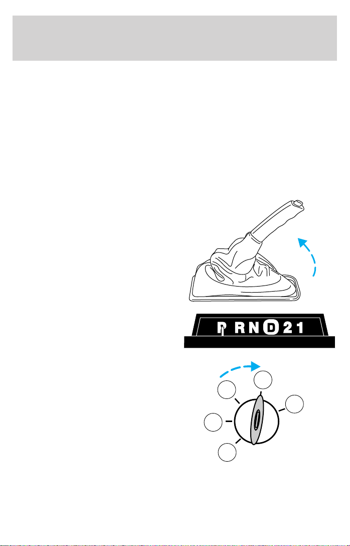
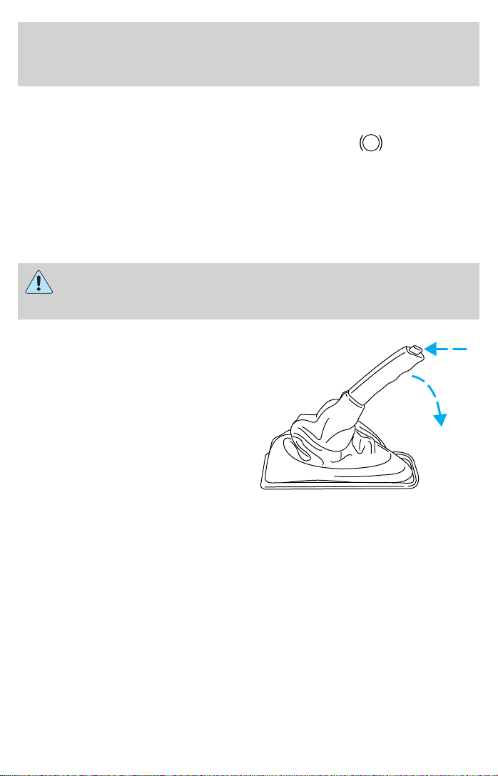
Understanding gearshift positions
Hold the brake pedal down while you move the gearshift lever
from P (Park) to another position. If you do not hold the brake
pedal down, your vehicle may move unexpectedly and injure someone.
P (Park)
To put your vehicle in gear, start the engine, depress the brake pedal,
then move gearshift lever out of P (Park).
Always come to a complete stop
before shifting into P (Park). Make
sure the gearshift lever is securely
latched in P (Park). This position
locks the transmission and prevents the rear wheels from turning.
Always set the parking brake fully and make sure the gearshift is
latched in P (Park). Turn off the ignition whenever you leave
your vehicle.
R (Reverse)
With the gearshift in R (Reverse),
the vehicle will move backward.
Always come to a complete stop
before shifting into and out of R
(Reverse).
N (Neutral)
With the gearshift lever in N
(Neutral), the vehicle can be started
and is free to roll. Hold the brake
pedal down while in this position.
(Overdrive)
The normal driving position for the
best fuel economy. Transmission
operates in gears one through five.
28
Page 29

Driving
(Overdrive) can be deactivated
by pressing the transmission control
switch on the end of the gearshift
lever.
Drive – Not shown on the gearshift position display. Activate by pressing
the transmission control switch on the end of the gearshift lever with the
gearshift lever in the
position. The Transmission Control Indicator
Light (TCIL) will illuminate on the instrument cluster. The transmission
operates in gears one through four.
braking than
(Overdrive) and is useful whenever driving conditions
(Drive) provides more engine
(i.e., city traffic, hilly terrain, etc.) cause the transmission to excessively
shift between
(Overdrive) and (Drive). Also deactivate
(Overdrive) when:
• driving with a heavy load.
• towing a trailer up or down steep hills.
• additional engine braking is desired. If towing a trailer, refer to
Driving while you tow in the Trailer Towing chapter.
To return to
(Overdrive) mode, press the transmission control
switch.
Each time the vehicle is started, the transmission will automatically
return to normal overdrive mode.
2 (Second)
Use 2 (Second) to start-up on
slippery roads or to provide
additional engine braking on
downgrades.
O/D
ON/OFF
1 (First)
Use 1 (First) to provide maximum
engine braking on steep downgrades.
Upshifts can be made by shifting to 2
(Second) or to
(Overdrive).
Selecting 1 (Low) at higher speeds
causes the transmission to shift to a lower gear and will shift to 1 (First)
after the vehicle decelerates to the proper vehicle speed.
29
Page 30

Driving
Forced Downshifts
To gain acceleration in (Overdrive) or Drive (O/D OFF) when
passing another vehicle, push the accelerator to the floor. The
transmission will downshift to the appropriate gear: fourth, third, second
or first gear.
FOUR-WHEEL DRIVE (4WD) OPERATION (IF EQUIPPED)
When Four-wheel drive (4WD) is engaged, power is supplied to all four
wheels through a transfer case. 4WD power can be selected when
additional driving power is desired.
If equipped with the Electronic Shift 4WD System, and the 4x4
Low button is pressed while the vehicle is moving, the system will
not engage and no damage will occur to the 4WD system.
4x4 High and 4x4 Low operation is not recommended on dry
pavement. Doing so could result in difficult disengagement of the
transfer case, increased tire wear and decreased fuel economy.
Positions of the 4WD system
The 4WD system functions in two modes:
• The 4x4 High mode provides
four-wheel drive with full power
to both axles. It is only intended
for severe winter or off-road
conditions, such as deep snow
and ice (where no dry or wet
pavement remains uncovered),
and shallow sand.
4x2
4x4
HIGH
LOW
• The 4x4 Low mode supplies
four-wheel drive with full power
to both axles and includes a
lower gear ratio for low-speed. It
is only intended for off-road
applications that require extra
power including deep sand, steep
grades and pulling a boat and
trailer out of the water.
30
4x2
4x4
HIGH
LOW
Page 31

Driving
The vehicle should not be operated in 4x4 High and 4x4 Low on
dry or merely wet pavement. Doing so will produce excessive
noise, increase tire wear and may damage driveline components.
These modes are intended for use only on consistently slippery or
loose surfaces.
If your vehicle is equipped with 4WD, a spare tire of a different
size than the road tires should never be used. Such a tire could
result in damage to driveline components and make the vehicle
difficult to control.
Utility and four-wheel drive vehicles are not designed for
cornering at speeds as high as passenger cars any more than
low-slung sports cars are designed to perform satisfactorily under
off-road conditions. Avoid sharp turns or abrupt maneuvers in these
vehicles.
Driving with 4WD
Your vehicle is specially equipped for driving on sand, snow, mud and
rough terrain and has operating characteristics that are somewhat
different from conventional vehicles, both on and off the road.
Maintain steering wheel control at all times, especially in rough terrain.
Since sudden changes in terrain can result in abrupt steering wheel
motion, make sure you grip the steering wheel from the outside. Do not
grip the spokes.
If your vehicle gets stuck
If the vehicle is stuck in mud or snow it may be rocked out by shifting
from forward and reverse gears, stopping between shifts, in a steady
pattern. Press lightly on the accelerator in each gear.
Do not rock the vehicle if the engine is not at normal operating
temperature or damage to the transmission may occur.
Do not rock the vehicle for more than a few minutes or damage
to the transmission and tires may occur or the engine may
overheat.
Do not spin the wheels at over 56 km/h (35 mph). The tires may
fail and injure a passenger or bystander.
31
Page 32

Driving
Sand
When driving over sand, try to keep all four wheels on the most solid
area of the trail. Do not reduce the tire pressures but shift to a lower
gear and drive steadily through the terrain. Apply the accelerator slowly
and avoid spinning the wheels.
Mud and water
If you must drive through high water, drive slowly. Traction or brake
capability may be limited.
When driving through water, determine the depth; avoid water higher
than the bottom of the hubs (if possible) and proceed slowly. If the
ignition system gets wet, the vehicle may stall.
Once through water, always try the brakes. Wet brakes do not stop the
vehicle as effectively as dry brakes. Drying can be improved by moving
your vehicle slowly while applying light pressure on the brake pedal.
After driving through mud, clean off residue stuck to rotating driveshafts
and tires. Excess mud stuck on tires and rotating driveshafts causes an
imbalance that could damage drive components.
If the transmission, transfer case or front axle are submerged in water,
their fluids should be checked and changed, if necessary.
Water intrusion into the transmission may damage the
transmission.
If the rear axle is submerged in water, the rear axle lubricant should be
checked and changed, if necessary. The rear axle is filled with a
synthetic lubricant and does not normally require a lubricant change for
the life of the vehicle. Rear axle lubricant quantities should not need to
be checked unless a leak is suspected.
Driving on hilly or sloping terrain
When climbing a steep hill, start in a lower gear rather than downshifting
to a lower gear from a higher gear once the ascent has started. This
reduces the strain on the engine.
When descending a steep hill, avoid sudden braking. Shift to a lower gear
when added engine braking is desired.
Automatic transmissions may shift frequently while driving up steep
grades. Eliminate frequent shifting by shifting out of
D (Drive).
(Overdrive) into
32
Page 33

Driving
Driving on snow and ice
A 4WD vehicle has advantages over 2WD vehicles in snow and ice but
can skid like any other vehicle.
Avoid sudden applications of power and quick changes of direction on
snow and ice. Apply the accelerator slowly and steadily when starting
from a full stop.
When braking, apply the brakes as you normally would. In order to allow
the anti-lock brake system (ABS) to operate properly, keep steady
pressure on the brake pedal.
Allow more stopping distance and drive slower than usual. Consider
using one of the lower gears.
33
Page 34

Roadside emergencies
RESETTING THE FUEL PUMP SHUT-OFF SWITCH
FUEL
RESET
The fuel pump shut-off switch is a device intended to stop the electric
fuel pump when your vehicle has been involved in a substantial jolt.
After a collision, if the engine cranks but does not start, the fuel pump
shut-off switch may have been activated.
The fuel pump shut-off switch is located in the center of the dash on the
dash panel.
Use the following procedure to reset
the fuel pump shut-off switch.
1. Turn the ignition to the OFF
position.
2. Check the fuel system for leaks.
3. If no fuel leak is apparent, reset
the fuel pump shut-off switch by
pushing in on the reset button.
4. Turn the ignition to the ON
position. Pause for a few seconds and return the key to the OFF
position.
5. Make a further check for leaks in the fuel system.
FUSES AND RELAYS
Fuses
If electrical components in the
vehicle are not working, a fuse may
have blown. Blown fuses are
identified by a broken wire within
the fuse. Check the appropriate
15
fuses before replacing any electrical
components.
Always replace a fuse with one that has the specified amperage
rating. Using a fuse with a higher amperage rating can cause
severe wire damage and could start a fire.
34
Page 35

Roadside emergencies
Standard fuse amperage rating and color
COLOR
Fuse
Rating
2A Grey Grey — — —
3A Violet Violet — — —
4A Pink Pink — — —
5A Tan Tan — — —
7.5A Brown Brown — — —
10A Red Red — — —
15A Blue Blue — — —
20A Yellow Yellow Yellow Blue Blue
25A Natural Natural — — —
30A Green Green Green Pink Pink
40A — — Orange Green Green
50A — — Red Red Red
60A — — Blue — Yellow
70A — — Tan — Brown
80A — — Natural — Black
Mini
Fuses
Standard
Fuses
Maxi
Fuses
Cartridge
Maxi
Fuses
Fuse Link
Cartridge
Passenger compartment fuse panel
The fuse panel is located beneath the right side of the instrument panel.
To remove a fuse use the fuse puller tool provided on the fuse panel
cover.
35
Page 36

Roadside emergencies
36
27 28
1234
5678
9 101112
13 14 15 16
17 18 19 20
21 22 23 24
25 26
The fuses are coded as follows:
Fuse/Relay
Location
Fuse Amp
Rating
Passenger Compartment
Fuse Panel Description
1 15A 4 x 4 Module
2 7.5A Blower Motor Relay
3 — Not Used
4 15A Left Headlamp
5 10A Data Link Connector (OBD II)
6 20A Defrost/Fan
7 — Not Used
8 15A Right Headlamp
9 — Not Used
10 7.5A Shift Lock Actuator, Turn Signals,
4 x 4 Module
11 7.5A Instrument Cluster (Warning Lamps),
4 x 4 Module, Flex Fuel Sender Module
12 — Not Used
29 30
35
32
31
34
33
36
Page 37

Roadside emergencies
Fuse/Relay
Location
13 15A EEC System, Stop Lamps, Four Wheel
14 10A Four Wheel Anti-Lock Brake System
15 7.5A Alternator Warning Lamp
16 30A Windshield Wiper Motor, Wiper Module
17 25A Cigar Lighter
18 — Not Used
19 25A EEC System, Ignition Coil
20 — Not Used
21 15A Flasher (Hazard)
22 — Not Used
23 — Not Used
24 7.5A Starter Relay
25 7.5A Speedometer
26 10A Interior Lamps
27 15A Backup Lamps, Overdrive Cancel
28 — Not Used
29 — Not Used
30 — Not Used
31 — Not Used
32 — Not Used
33 5A Headlamps (Highbeams)
34 — Not Used
35 7.5A RH Park Lamps
36 7.5A LH Park Lamps
Fuse Amp
Rating
Passenger Compartment
Fuse Panel Description
Anti-Lock Brake System (4WABS),
4 x 4 Module
(4WABS) Module
Power distribution box
The power distribution box is located in the engine compartment. The
power distribution box contains high-current fuses that protect your
vehicle’s main electrical systems from overloads.
37
Page 38

Roadside emergencies
Always disconnect the battery before servicing high current
fuses.
Always replace the cover to the Power Distribution Box before
reconnecting the battery or refilling fluid reservoirs.
If the battery has been disconnected and reconnected, refer to the
Battery section of the Maintenance and care chapter.
5
3
1
4
175A
13
14
11
12
87
10 9
6
The high-current fuses are coded as follows:
Fuse/Relay
Location
Fuse Amp
Rating
Power Distribution Box Description
1 20A** 4 x 4 System
2 30A** EEC Power
3 20A** Fuel System
4 30A** Headlamps
5 50A** ABS System
6 30A** ABS System
7 — Not Used
8 — Not Used
9 40A** Blower Motor
10 — Not Used
11 — Not Used
12 — Not Used
13 60A** I/P Fuse Panel
14 50A** Ignition
1 15A* Parking Lamps
5
21
76
3
8
4
6
D10DE2
9
4
5
10
11
322
1
38
Page 39

Roadside emergencies
Fuse/Relay
Location
Fuse Amp
Rating
Power Distribution Box Description
2 — Not Used
3 — Not Used
4 — Not Used
5 10A* EEC Memory
6 — Not Used
7 15A* Horn
8 — Not Used
9 — Not Used
10 30A* Alternator System
11 15A* EEC Hego System
1 — LH Headlamp Relay
2 — Horn Relay
3 — RH Headlamp Relay
4 — Starter Relay
5 — EEC Power Relay
6 — Blower Relay
Diode 2 — EEC Diode
* Mini Fuses ** Maxi Fuses
Relay module
The relay box is located in the right front corner of the engine
compartment.
1
2
3
4
5
6
7
39
Page 40

Roadside emergencies
The relays are coded as follows:
Relay location Description
1 Side Marker Isolation Relay
2 Fuel Pump Relay
3 Rear Hazard Isolation Relay
4 LH Repeater/Marker Relay
5 RH Repeater/Marker Relay
6 LH Turn/Hazard Relay
7 RH Turn/Hazard Relay
CHANGING THE TIRES
If you get a flat tire while driving, do not apply the brake heavily.
Instead, gradually decrease your speed. Hold the steering wheel firmly
and slowly move to a safe place on the side of the road.
Tire change procedure
To prevent the vehicle from moving when you change a tire, be
sure the parking brake is set, then block (in both directions) the
wheel that is diagonally opposite (other side and end of the vehicle) to
the tire being changed.
If the vehicle slips off the jack, you or someone else could be
seriously injured.
1. Park on a level surface, activate
hazard flashers and set the parking
brake.
2. Place gearshift lever in P (Park)
and turn engine OFF.
40
Page 41

Roadside emergencies
When one of the rear wheels is off the ground, the transmission
alone will not prevent the vehicle from moving or slipping off the
jack, even if the transmission is in P (Park).
3. Block the diagonally opposite
wheel.
4. Loosen each wheel lug nut, but
do not remove them until the wheel
is raised off the ground.
5. Position the jack according to the following guides and turn the jack
handle clockwise until the tire is a maximum of 25 mm (1 inch) off the
ground.
• Front
41
Page 42

Roadside emergencies
• Rear
To lessen the risk of
personal injury, do not put
any part of your body under the
vehicle while changing a tire. Do
not start the engine when your
vehicle is on the jack. The jack is
only meant for changing the tire.
• Never use the front or rear
differential as a jacking point.
6. Remove the lug nuts with the lug wrench.
7. Replace the flat tire with the spare tire, making sure the valve stem is
facing outward. Reinstall the lug nuts, cone side in, until the wheel is
snug against the hub. Do not fully tighten the lug nuts until the wheel
has been lowered.
8. Lower the wheel by turning the jack handle counterclockwise.
42
Page 43

Roadside emergencies
9. Remove the jack and fully tighten
the lug nuts in the order shown.
10. Stow the flat tire, jack and lug
wrench. Make sure the jack is
fastened so it does not rattle when
you drive.
11. Unblock the wheels.
JUMP STARTING YOUR VEHICLE
The gases around the battery can explode if exposed to flames,
sparks, or lit cigarettes. An explosion could result in injury or
vehicle damage.
Do not push start your vehicle. You could damage the catalytic
converter.
Batteries contain sulfuric acid which can burn skin, eyes, and
clothing, if contacted.
Do not attempt to push start your vehicle. Automatic
transmissions do not have push-start capability.
1
43
25
Preparing your vehicle
When the battery is disconnected or a new battery is installed, the
transmission must relearn its adaptive strategy. As a result of this, the
transmission may shift firmly. This operation is considered normal and
will not effect function or durability of the transmission. Over time, the
adaptive learning process will fully update transmission operation to its
optimum shift feel.
1. Use only a 12–volt supply to start your vehicle.
2. Do not disconnect the battery of the disabled vehicle as this could
damage the vehicle’s electrical system.
3. Park the booster vehicle close to the hood of the disabled vehicle
making sure the two vehicles do not touch. Set the parking brake on
43
Page 44

Roadside emergencies
both vehicles and stay clear of the engine cooling fan and other moving
parts.
4. Check all battery terminals and remove any excessive corrosion before
you attach the battery cables. Ensure that vent caps are tight and level.
5. Turn the heater fan on in both vehicles to protect any electrical
surges. Turn all other accessories off.
Connecting the jumper cables
1. Connect the positive (+) booster cable to the positive (+) terminal of
the discharged battery.
Note: In the illustrations, lightning bolts are used to designate the
assisting (boosting) battery.
+
–
2. Connect the other end of the positive (+) cable to the positive (+)
terminal of the assisting battery.
+
–
44
+
–
+
–
Page 45

Roadside emergencies
3. Connect the negative (-) cable to the negative (-) terminal of the
assisting battery.
+
–
4. Make the final connection of the negative (-) cable to an exposed
metal part of the stalled vehicle’s engine, away from the battery and the
carburetor/fuel injection system.
Do not use fuel lines, engine rocker covers or the intake manifold as
grounding points.
Do not connect the end of the second cable to the negative (-)
terminal of the battery to be jumped. A spark may cause an
explosion of the gases that surround the battery.
+
–
45
Page 46

Roadside emergencies
• 4.0L SOHC
+
–
5. Ensure that the cables are clear of fan blades, belts, moving parts of
both engines, or any fuel delivery system parts.
+
–
Jump starting
1. Start the engine of the booster vehicle and run the engine at
moderately increased speed.
2. Start the engine of the disabled vehicle.
3. Once the disabled vehicle has been started, run both engines for an
additional three minutes before disconnecting the jumper cables.
46
Page 47

Roadside emergencies
Removing the jumper cables
Remove the jumper cables in the reverse order that they were
connected.
1. Remove the jumper cable from the ground metal surface.
• 4.0L SOHC
+
–
+
–
+
–
+
–
2. Remove the jumper cable on the negative (-) connection of the
booster vehicle’s battery.
47
Page 48

Roadside emergencies
+
–
3. Remove the jumper cable from the positive (+) terminal of the booster
vehicle’s battery.
+
–
+
–
+
–
4. Remove the jumper cable from the positive (+) terminal of the
disabled vehicle’s battery.
When the battery is disconnected or a new battery is installed, the
transmission must relearn its adaptive strategy. As a result of this, the
transmission may shift firmly. This operation is considered normal and
will not effect function or durability of the transmission. Over time, the
adaptive learning process will fully update transmission operation to its
optimum shift feel.
48
Page 49

Roadside emergencies
WRECKER TOWING
If the vehicle needs towing, a wheel lift or flatbed equipment is
recommended.
If a slingbelt or J-hook method is used, towing the vehicle from the rear
is recommended.
If the vehicle must be towed from the front with a slingbelt or J-hook,
the air dam may be damaged unless it is protected by using a wooden
crossbeam and spacer block assembly.
Although not desired, it is permissible to tow with the rear wheels on the
ground with the speed and distance limitations.
• Place the transmission in N(Neutral).
• Do not exceed a distance of 80 km (50 miles).
• Do not exceed 56 km/h (35 mph) vehicle speed.
If a distance of 80 km (50 miles) and/or a vehicle speed of 56 km/h (35
mph) must be exceeded, the drive shaft must be removed prior to
towing.
To protect the air dam, refer to the following instructions and
illustrations
1. Position the wooden crossbeam and spacer block assembly under the
frame rails, behind the front bumper and air dam.
2. Install the tow chains through the notches in the air dam and below
the crossbeam and spacer block assembly.
3. Hook the tow chains over the curved cradles on the top of the lower
suspension A-arms.
49
Page 50

Roadside emergencies
FRONT OF
VEHICLE
1
4
6
Item Description
1 Frame rails
2 Front bumper
3 Air dam
4 Tow chain notches
5 Wooden beam
6 Wooden spacer blocks
2
3
4
5
50
Page 51

Roadside emergencies
The following is list of materials required for the wooden crossbeam and
spacer block assembly.
1
Item Quantity Description
1 1 4x4x60inch wood beam
2 4 2x4x6inch wood block
3 8 1/4 inch flat washer
4 8 1/4 inch hex nut
5 2 4x4x31/2inch wood block
6 8 1/4 x 7 inch carrage bolt
2
6
3
4
5
51
Page 52

Maintenance and care
SERVICE RECOMMENDATIONS
To help you service your vehicle:
• We highlight do-it-yourself items in the engine compartment for easy
location.
• We provide a scheduled maintenance guide which makes tracking
routine service easy.
If your vehicle requires professional service, your dealership can provide
the necessary parts and service. Check your “Warranty Guide” to find out
which parts and services are covered.
Use only recommended fuels, lubricants, fluids and service parts
conforming to specifications. Motorcraft parts are designed and built to
provide the best performance in your vehicle.
PRECAUTIONS WHEN SERVICING YOUR VEHICLE
Be especially careful when inspecting or servicing your vehicle.
• Do not work on a hot engine.
• When the engine is running, make sure that loose clothing, jewelry or
long hair does not get caught up in moving parts.
• Do not work on a vehicle with the engine running in an enclosed
space, unless you are sure you have enough ventilation.
• Keep all lit cigarettes, open flames and other lit material away from
the battery and all fuel related parts.
If you disconnect the battery, the engine must “relearn” its idle
conditions before your vehicle will drive properly, as explained in Battery
in this chapter.
Working with the engine off
1. Set the parking brake and ensure the gearshift is securely latched in P
(Park).
2. Turn off the engine and remove the key.
3. Block the wheels to prevent the vehicle from moving unexpectedly.
Working with the engine on
1. Set the parking brake and ensure the gearshift is securely latched in P
(Park).
2. Block the wheels to prevent the vehicle from moving unexpectedly.
52
Page 53

Maintenance and care
Do not start your engine with the air cleaner removed and do
not remove it while the engine is running.
IDENTIFYING COMPONENTS IN THE ENGINE COMPARTMENT
4.0L SOHC V6 ENGINE
1 2 3 4 5 6
10
1. Windshield washer fluid reservoir
2. Power distribution box
3. Brake fluid reservoir
4. Engine oil dipstick
5. Automatic transmission fluid dipstick
6. Engine oil filler cap
7. Battery
8. Radiator cap
9. Power steering fluid reservoir
9 78
53
Page 54

Maintenance and care
10. Air filter assembly
11. Engine coolant reservoir
ENGINE OIL
Checking the engine oil
Refer to the scheduled maintenance guide for the appropriate intervals
for checking the engine oil.
1. Make sure the vehicle is on level ground.
2. Turn the engine off and wait a few minutes for the oil to drain into the
oil pan.
3. Set the parking brake and ensure the gearshift is securely latched in P
(Park).
4. Open the hood. Protect yourself from engine heat.
5. Locate and carefully remove the engine oil level indicator (dipstick).
6. Wipe the indicator clean. Insert the indicator fully, then remove it
again.
• If the oil level is between the MIN and MAX marks, the oil level is
acceptable. DO NOT ADD OIL.
• If the oil level is below the MIN mark, add enough oil to raise the level
within the MIN-MAX range.
• Oil levels above the MAX mark may cause engine damage. Some oil
must be removed from the engine by a qualified service technician.
7. Put the indicator back in and ensure it is fully seated.
Adding engine oil
1. Check the engine oil. For instructions, refer to Checking the engine
oil in this chapter.
2. If the engine oil level is not within the normal range, add only certified
engine oil of the recommended viscosity. Remove the engine oil filler cap
and use a funnel to pour the engine oil into the opening.
3. Recheck the engine oil level. Make sure the oil level is not above the
FULL mark on the engine oil level indicator (dipstick).
4. Install the indicator and ensure it is fully seated.
5. Fully install the engine oil filler cap by turning the filler cap clockwise
until three clicks are heard or until it is latched.
54
Page 55

Maintenance and care
To avoid possible oil loss, DO NOT operate the vehicle with the
engine oil level indicator and/or the engine oil filler cap removed.
Engine oil and filter recommendations
SAE 5W-30 engine oil is recommended
Look for this certification
trademark.
Use SAE 5W-30 motor oil certified for gasoline engines by the American
Petroleum Institute (API).
Motor oil displaying the API certification trademark will meet all
requirements for your vehicle’s engine.
Ford oil specification is WSS-M2C153-G.
Do not use supplemental engine oil additives, oil treatments or engine
treatments. They are unnecessary and could, under certain conditions,
lead to engine damage which is not covered by your warranty.
Change your engine oil and filter according to the appropriate schedule
listed in the scheduled maintenance guide.
Ford production and aftermarket (Motorcraft) oil filters are designed for
added engine protection and long life. If a replacement oil filter is used
that does not meet Ford material and design specifications, start-up
engine noises or knock may be experienced.
It is recommended you use the appropriate Motorcraft oil filter (or
another brand meeting Ford specifications) for your engine application.
55
Page 56

Maintenance and care
BRAKE FLUID
Checking and adding brake fluid
Brake fluid should be checked and
refilled as needed. Refer to the
scheduled maintenance guide for
the service interval schedules.
1. Clean the reservoir cap before
removal to prevent dirt or water
from entering the reservoir.
2. Visually inspect the fluid level.
3. If necessary, add brake fluid from
a clean un-opened container until
the level reaches MAX. Do not fill
above this line.
4. Use only a DOT 3 brake fluid
certified to meet Ford specifications. Refer to Lubricant specifications
in the Capacities and specifications chapter.
Brake fluid is toxic. If brake fluid contacts the eyes, flush eyes
with running water for 15 minutes. Seek medical attention if
irritation persists. If taken internally, drink water and induce vomiting.
Seek medical attention immediately.
MAX
56
If you use a brake fluid that is not DOT 3, you will cause
permanent damage to your brakes.
Do not let the reservoir for the master cylinder run dry. This
may cause the brakes to fail.
Page 57

Maintenance and care
WINDSHIELD WASHER FLUID
Checking and adding washer fluid
Check the washer fluid whenever
you stop for fuel. The reservoir is
highlighted with a
If the level is low, add enough fluid
to fill the reservoir. In very cold
weather, do not fill the reservoir all
the way.
Only use a washer fluid that meets Ford specifications. Refer to
Lubricant specifications in the Capacities and specifications chapter.
State or local regulations on volatile organic compounds may restrict the
use of methanol, a common windshield washer antifreeze additive.
Washer fluids containing non-methanol antifreeze agents should be used
only if they provide cold weather protection without damaging the
vehicle’s paint finish, wiper blades or washer system.
symbol.
RADIATOR
COOLANT
ONLY
R
E
F
H
L
S
U
A
I
D
W
O
Y
N
L
Do not put washer fluid in the engine coolant reservoir. Washer
fluid placed in the cooling system may harm engine and cooling
system components.
ENGINE COOLANT
Checking engine coolant
Your engine’s cooloing system has been factory-filled with a 50/50
mixture of distilled water and Ford G05 Engine Coolant per Ford
Specification WSS-M97B51–A1.
A 50/50 mixture of distilled water and Ford G05 Engine Coolant
provides:
• maximum cooling system efficiency.
57
Page 58

Maintenance and care
• freeze protection down to -36° C (-34° F).
• boiling protection up to 129° C (265° F).
• protection against rust and other forms of corrosion.
• an accurate temperature readout from the engine coolant
gauge.
The engine coolant must be maintained at the correct fluid level
and concentration to work properly. If the engine coolant fluid
level and concentration is not maintained correctly, damage to
the engine and cooling system may result.
When the engine is cold, check the
level of the engine coolant in the
reservoir.
R
E
F
H
L
S
U
A
I
D
W
O
Y
N
L
RADIATOR
COOLANT
ONLY
• The engine coolant should be at the “cold fill level” or within the “cold
fill range” as listed on the engine coolant reservoir (depending upon
application).
• Refer to the scheduled maintenance guide for service interval
schedules.
• Be sure to read and understand Precautions when servicing your
vehicle in this chapter.
If the engine coolant has not been checked at the recommended interval,
the engine coolant reservoir may become low or empty. If the reservoir is
low or empty, add engine coolant to the reservoir. Refer to Adding
engine coolant in this chapter.
58
Page 59

Maintenance and care
Automotive fluids are not interchangeable; do not use engine
coolant, antifreeze or windshield washer fluid outside of its
specified function and vehicle location.
Adding engine coolant
Use only Ford Premium Engine Coolant E2FZ-19549-AA (in
Canada, Motorcraft CXC-10) or a premium engine coolant that
meets Ford specification ESE-M97B44-A. Use only Ford G05
Engine Coolant WSS—M97B51–A1 (in Canada, Motorcraft
CXC-10) or a premium engine coolant that meets Ford
specification ESE-M97B44-A.
• DO NOT USE Ford Extended Life Engine Coolant
F6AZ-19544-AA (orange in color).
• DO NOT USE a DEX-COOLt engine coolant or an equivalent
engine coolant that meets Ford specification WSS-M97B44-D.
• DO NOT USE alcohol or methanol antifreeze or any engine
coolants mixed with alcohol or methanol antifreeze.
• DO NOT USE supplemental coolant additives in your vehicle.
These additives may harm your engine’s cooling system.
• DO NOT MIX recycled coolant and conventional coolant
together in your vehicle. Mixing of engine coolants may harm
your engine’s cooling system.
• The use of an improper coolant may harm engine and cooling
system components and may void the warranty of your vehicle’s
engine cooling system. If you are unsure which type of coolant
your vehicle requires, contact your local dealer.
Do not put engine coolant in the windshield washer fluid
reservoir. If engine coolant is sprayed onto the windshield, it
could make it difficult to see through the windshield.
When the engine is cool, add a 50/50 mixture of engine coolant and
distilled water to the engine coolant reservoir, until the coolant is at the
“cold fill level” or within the “cold fill range” as listed in the engine
coolant reservoir (depending upon application).
• NEVER increase the coolant concentration above 60%.
59
Page 60

Maintenance and care
• NEVER decrease the coolant concentration below 40%.
• Engine coolant concentrations above 60% or below 40% will
decrease the freeze protection characteristics of the engine
coolant and may cause engine damage.
Plain water may be added in an emergency, but you must replace it with
a 50/50 mixture of engine coolant and distilled water as soon as possible.
Check the coolant level in the reservoir before you drive your vehicle the
next few times (with the engine cool). If necessary, add a 50/50
mixture of engine coolant and distilled water to the engine coolant
reservoir until the coolant level is at the “cold fill level” or within the
“cold fill range” as listed on the reservoir (depending upon application).
Have your dealer check the engine cooling system for leaks if you have
to add more than 1.0 liter (1.0 quart) of engine coolant per month.
To avoid scalding hot steam or coolant from being released from
the engine cooling system, never remove the reservoir cap while
the engine is running or hot. Failure to follow this warning may result
in damage to the engine’s cooling system and possible severe personal
injury.
If you must remove the coolant cap, follow these steps to avoid personal
injury:
1. Before you remove the cap, turn the engine off and let it cool.
2. When the engine is cool, wrap a thick cloth around the cap. Slowly
turn cap counterclockwise until pressure begins to release.
3. Step back while the pressure releases.
4. When you are sure that all the pressure has been released, use the
cloth to turn it counterclockwise and remove the cap.
Recycled engine coolant
Ford Motor Company recommends the use of a recycled engine coolant
produced by Ford-approved processes.
Not all coolant recycling processes produce coolant which meets Ford
specification WSS-M97B51–A1. Use of a recycled engine coolant which
does not meet the Ford G05 specification may harm engine and cooling
system components.
60
Page 61

Maintenance and care
Always dispose of used automotive fluids in a responsible manner.
Follow your community’s regulations and standards for recycling and
disposing of automotive fluids.
Coolant refill capacity
To find out how much fluid your vehicle’s cooling system can hold, refer
to Refill capacities in the Capacities and specifications chapter.
Fill your engine coolant reservoir as outlined in Adding engine coolant
in this chapter.
Severe climates
If you drive in extremely cold climates (less than –36° C [–34° F]):
• it may be necessary to increase the coolant concentration
above 50%.
• NEVER increase the coolant concentration above 60%.
• increased engine coolant concentrations above 60% will
decrease the overheat protection characteristics of the engine
coolant and may cause engine damage.
• refer to the chart on the coolant container to ensure the
coolant concentration in your vehicle will provide adequate
freeze protection at the temperatures in which you drive in the
winter months.
If you drive in extremely hot climates:
• it is still necessary to maintain the coolant concentration
above 40%.
• NEVER decrease the coolant concentration below 40%.
• decreased engine coolant concentrations below 40% will
decrease the corrosion protection characteristics of the engine
coolant and may cause engine damage.
• decreased engine coolant concentrations below 40% will
decrease the freeze protection characteristics of the engine
coolant and may cause engine damage.
• refer to the chart on the coolant container to ensure the
coolant concentration in your vehicle will provide adequate
protection at the temperatures in which you drive.
61
Page 62

Maintenance and care
Vehicles driven year-round in non-extreme climates should use a 50/50
mixture of engine coolant and distilled water for optimum cooling system
and engine protection.
CHECKING AND ADDING POWER STEERING FLUID
Check the power steering fluid.
Refer to the scheduled maintenance
guidefor the service interval
schedules. If adding fluid is
necessary, use only MERCONt ATF.
O
D
N
O
T
E
R
V
F
O
I
L
L
G
N
D
I
P
I
F
U
L
O
R
E
W
E
E
T
R
S
1. Start the engine and let it run until it reaches normal operating
temperature (the engine coolant temperature gauge indicator will be
near the center of the normal area between H and C).
2. While the engine idles, turn the steering wheel left and right several
times.
3. Turn the engine off.
4. Check the fluid level in the reservoir.
5. The fluid level should be between the MIN and MAX lines. Do not add
fluid if the level is in this range.
6. If the fluid is low, add fluid in small amounts, continuously checking
the level until it reaches the correct operating range. Be sure to put the
cap back on the reservoir.
TRANSMISSION FLUID
Checking automatic transmission fluid
Refer to your scheduled maintenance guide for scheduled intervals for
fluid checks and changes. Your transmission does not consume fluid.
However, the fluid level should be checked if the transmission is not
62
Page 63

Maintenance and care
working properly, i.e., if the transmission slips or shifts slowly or if you
notice some sign of fluid leakage.
Automatic transmission fluid expands when warmed. To obtain an
accurate fluid check, drive the vehicle until it is warmed up
(approximately 30 km [20 miles]). If your vehicle has been operated for
an extended period at high speeds, in city traffic during hot weather or
pulling a trailer, the vehicle should be turned off for about 30 minutes to
allow fluid to cool before checking.
1. Drive the vehicle 30 km (20 miles) or until it reaches normal operating
temperature.
2. Park the vehicle on a level surface and engage the parking brake.
3. With the parking brake engaged and your foot on the brake pedal,
start the engine and move the gearshift lever through all of the gear
ranges. Allow sufficient time for each gear to engage.
4. Latch the gearshift lever in P (Park) and leave the engine running.
5. Remove the dipstick, wiping it clean with a clean, dry lint free rag. If
necessary, refer to Identifying components in the engine compartment
in this chapter for the location of the dipstick.
6. Install the dipstick making sure it is fully seated in the filler tube.
7. Remove the dipstick and inspect the fluid level. The fluid should be in
the designated area for normal operating temperature or ambient
temperature.
Low fluid level
Do not drive the vehicle if the fluid
level is at the bottom of the dipstick
and the outside temperatures are
above 10°C (50°F).
H
Correct fluid level
The transmission fluid should be checked at normal operating
temperatures 66°C-77°C (150°F-170°F) on a level surface. The normal
operating temperature can be reached after approximately 30 km (20
miles) of driving. However, you can check the fluid without driving if the
ambient temperatures are above 10°C (50°F). If fluid is added at this
time, an overfill condition could result when the vehicle reaches normal
operating temperature.
63
Page 64

Maintenance and care
The transmission fluid should be in
this range if at normal operating
temperature (66°C-77°C
[150°F-170°F]).
H
High fluid level
Fluid levels above the safe range
may result in transmission failure.
An overfill condition of transmission
fluid may cause shift and/or
engagement concerns and/or
possible damage.
High fluid levels can be caused by an overheating condition.
H
Adjusting automatic transmission fluid levels
Before adding any fluid, make sure the correct type is used. The type of
fluid used is normally indicated on the dipstick and also in the
Lubricant specifications section in the Capacities and specifications
chapter.
Use of a non-approved automatic transmission fluid may cause
internal transmission component damage.
If necessary, add fluid in 250 mL (1/2 pint) increments through the filler
tube until the level is correct.
If an overfill occurs, excess fluid
should be removed by a qualified
technician.
An overfill condition of
transmission fluid may cause
shift and/or engagement concerns and/or possible damage.
H
DRIVELINE UNIVERSAL JOINT AND SLIP YOKE
Your vehicle may be equipped with universal joints that require
lubrication. Refer to the scheduled maintenance guide for maintenance
intervals. If the original universal joints are replaced with universal joints
equipped with grease fittings, lubrication will also be necessary.
64
Page 65

Maintenance and care
BATTERY
Your vehicle is equipped with a
Motorcraft maintenance-free battery
which normally does not require
additional water during its life of
service.
However, for severe usage or in high temperature climates, check the
battery electrolyte level. Refer to the scheduled maintenance guide for
the service interval schedules.
Keep the electrolyte level in each cell up to the “level indicator”.
Do not overfill the battery cells.
If the electrolyte level in the battery is low, you can add plain tap water
to the battery, as long as you do not use hard water (water with a high
mineral or alkali content). If possible, however, try to only fill the battery
cells with distilled water. If the battery needs water often, have the
charging system checked.
If your battery has a cover/shield, make sure it is reinstalled
after the battery has been cleaned or replaced.
For longer, trouble-free operation, keep the top of the battery clean and
dry. Also, make certain the battery cables are always tightly fastened to
the battery terminals.
If you see any corrosion on the battery or terminals, remove the cables
from the terminals and clean with a wire brush. You can neutralize the
acid with a solution of baking soda and water.
When the battery is disconnected or a new battery installed, the
transmission must learn its adaptive strategy. As a result of this, the
transmission may shift firmly. This operation is considered normal and
will fully update transmission operation to its optimum shift feel.
65
Page 66

Maintenance and care
Batteries normally produce explosive gases which can cause
personal injury. Therefore, do not allow flames, sparks or lighted
substances to come near the battery. When working near the battery,
always shield your face and protect your eyes. Always provide proper
ventilation.
When lifting a plastic-cased battery, excessive pressure on the
end walls could cause acid to flow through the vent caps,
resulting in personal injury and/or damage to the vehicle or battery.
Lift the battery with a battery carrier or with your hands on opposite
corners.
Keep batteries out of reach of children. Batteries contain sulfuric
acid. Avoid contact with skin, eyes or clothing. Shield your eyes
when working near the battery to protect against possible splashing of
acid solution. In case of acid contact with skin or eyes, flush
immediately with water for a minimum of 15 minutes and get prompt
medical attention. If acid is swallowed, call a physician immediately.
Battery posts, terminals and related accessories contain lead and
lead compunds. Wash hands after handling.
Because your vehicle’s engine is electronically controlled by a computer,
some control conditions are maintained by power from the battery. When
the battery is disconnected or a new battery is installed, the engine must
relearn its idle and fuel trim strategy for optimum driveability and
performance. To begin this process:
1. With the vehicle at a complete stop, set the parking brake.
2. Put the gearshift in P (Park), turn off all accessories and start the
engine.
3. Run the engine until it reaches normal operating temperature.
4. Allow the engine to idle for at least one minute.
5. Turn the A/C on and allow the engine to idle for at least one minute.
6. Drive the vehicle to complete the relearning process.
66
Page 67

Maintenance and care
• The vehicle may need to be driven to relearn the idle and fuel trim
strategy.
• If you do not allow the engine to relearn its idle trim, the idle
quality of your vehicle may be adversely affected until the idle
trim is eventually relearned.
When the battery is disconnected or a new battery installed, the
transmission must relearn its adaptive strategy. As a result of this, the
transmission may shift firmly. This operation is considered normal and
will not affect function or durability of the transmission. Over time the
adaptive learning process will fully update transmission operation to its
optimum shift feel.
If the battery has been disconnected or a new battery has been installed,
the clock and the preset radio stations must be reset once the battery is
reconnected.
• Always dispose of automotive
batteries in a responsible manner.
Follow your local authorized
standards for disposal. Call your
local authorized recycling center
to find out more about recycling
automotive batteries.
LEAD
RECYCLE
RETURN
INFORMATION ABOUT UNIFORM TIRE QUALITY GRADING
New vehicles are fitted with tires
that have a rating on them called
Tire Quality Grades. The Quality
grades can be found where
applicable on the tire sidewall
between tread shoulder and
maximum section width. For
example:
• Treadwear 200 Traction AA Temperature A
These Tire Quality Grades are determined by standards that the United
States Department of Transportation has set.
67
Page 68

Maintenance and care
Tire Quality Grades apply to new pneumatic tires for use on passenger
cars. They do not apply to deep tread, winter-type snow tires,
space-saver or temporary use spare tires, tires with nominal rim
diameters of 10 to 12 inches or limited production tires as defined in
Title 49 Code of Federal Regulations Part 575.104(c)(2).
U.S. Department of Transportation-Tire quality grades: The U.S.
Department of Transportation requires Ford to give you the following
information about tire grades exactly as the government has written it.
Treadwear
The treadwear grade is a comparative rating based on the wear rate of
the tire when tested under controlled conditions on a specified
government test course. For example, a tire graded 150 would wear one
and one-half (1 1/2) times as well on the government course as a tire
graded 100. The relative performance of tires depends upon the actual
conditions of their use, however, and may depart significantly from the
norm due to variations in driving habits, service practices, and
differences in road characteristics and climate.
Traction AA A B C
The traction grades, from highest to lowest are AA, A, B, and C. Those
grades represent the tire’s ability to stop on wet pavement as measured
under controlled conditions on specified government test surfaces of
asphalt and concrete. A tire marked C may have poor traction
performance.
The traction grade assigned to this tire is based on
straight-ahead braking traction tests, and does not include
acceleration, cornering, hydroplaning or peak traction characteristics.
Temperature A B C
The temperature grades are A (the highest), B, and C, representing the
tire’s resistance to the generation of heat and its ability to dissipate heat
when tested under controlled conditions on a specified indoor laboratory
test wheel. Sustained high temperature can cause the material of the tire
to degenerate and reduce tire life, and excessive temperature can lead to
sudden tire failure. The grade C corresponds to a level of performance
which all passenger car tires must meet under the Federal Motor Vehicle
Safety Standard No. 109. Grades B and A represent higher levels of
performance on the laboratory test wheel than the minimum required by
law.
68
Page 69

Maintenance and care
The temperature grade for this tire is established for a tire that
is properly inflated and not overloaded. Excessive speed,
underinflation, or excessive loading, either separately or in
combination, can cause heat buildup and possible tire failure.
SERVICING YOUR TIRES
Checking the tire pressure
• Use an accurate tire pressure gauge.
• Check the tire pressure when tires are cold, after the vehicle has been
parked for at least one hour or has been driven less than 5 km (3
miles).
• Adjust tire pressure to recommended specifications found on the
Certification Label or the Tire Label.
Improperly inflated tires can affect vehicle handling and can fail
suddenly, possibly resulting in loss of vehicle control.
Tire rotation
Because your vehicle’s tires perform different jobs, they often wear
differently. To make sure your tires wear evenly and last longer, rotate
them as indicated in the scheduled maintenance guide. If you notice that
the tires wear unevenly, have them checked.
• Four tire rotation
69
Page 70

Maintenance and care
Replacing the tires
Replace the tires when the wear
band is visible through the tire
treads.
When replacing full size tires, never mix radial bias-belted, or
bias-type tires. Use only the tire sizes that are listed on the
Certification Label. Make sure that all tires are the same size, speed
rating, and load-carrying capacity. Use only the tire combinations
recommended on the label. If you do not follow these precautions,
your vehicle may not drive properly and safely.
Make sure that all replacement tires are of the same size, type,
load-carrying capacity and tread design (e.g., “All Terrain”, etc.),
as originally offered by Ford.
Do not replace your tires with “high performance” tires or larger
size tires.
Failure to follow these precautions may adversely affect the
handling of the vehicle and make it easier for the driver to lose
control and roll over.
Tires that are larger or smaller than your vehicle’s original tires may also
affect the accuracy of your speedometer.
70
Page 71

Maintenance and care
USING SNOW TIRES AND TRACTION DEVICES
Snow tires must be the same size and grade as the tires you
currently have on your vehicle.
The tires on your vehicle have all-weather treads to provide traction in
rain and snow. However, in some climates, using snow tires and traction
devices may be necessary. Ford offers tire cables as a Ford approved
accessory and recommends use of these or their equivalents. See your
dealer or qualified service technician for more information on tire cables
for your vehicle.
Follow these guidelines when using snow tires and traction devices:
• Install cables securely, verifying that the cables do not touch any
wiring, brake lines or fuel lines.
• Drive cautiously. If you hear the cables rub or bang against the
vehicle, stop and retighten them. If this does not work, remove the
cables to prevent vehicle damage.
• Avoid overloading your vehicle.
• Remove the tire cables when they are no longer needed.
• Do not use cables on dry roads.
• The suspension insulation and bumpers will help prevent vehicle
damage. Do not remove these components from the vehicle when
using snow tires and traction devices.
• Do not exceed 48 km/h (30 mph) with tire cables on your vehicle.
Consult your dealer for information on other Ford approved methods of
traction control.
WHAT YOU SHOULD KNOW ABOUT AUTOMOTIVE FUELS
Important safety precautions
Do not overfill the fuel tank. The pressure in an overfilled tank
may cause leakage and lead to fuel spray and fire.
71
Page 72

Maintenance and care
The fuel system may be under pressure. If the fuel filler cap is
venting vapor or if you hear a hissing sound, wait until it stops
before completely removing the fuel filler cap. Otherwise, fuel may
spray out and injure you or others.
If you do not use the proper fuel filler cap, excessive pressure or
vacuum in the fuel tank may damage the fuel system or cause
the fuel cap to disengage in a collision, which may result in possible
personal injury.
Automotive fuels can cause serious injury or death if misused or
mishandled.
Fuel ethanol and gasoline may contain benzene, which is a
cancer-causing agent.
Observe the following guidelines when handling automotive fuel:
• Extinguish all smoking materials
and any open flames before
fueling your vehicle.
• Always turn off the vehicle before
fueling.
• Automotive fuels can be harmful
or fatal if swallowed. Fuels such
as gasoline and ethanol are highly
toxic and if swallowed can cause
death or permanent injury. If fuel
is swallowed, call a physician immediately, even if no symptoms are
immediately apparent. The toxic effects of fuel may not be visible for
hours.
• Avoid inhaling fuel vapors. Inhaling too much fuel vapor of any kind
can lead to eye and respiratory tract irritation. In severe cases,
excessive or prolonged breathing of fuel vapor can cause serious
illness and permanent injury.
72
Page 73

Maintenance and care
• Avoid getting fuel liquid in your eyes. If fuel is splashed in the eyes,
remove contact lenses (if worn), flush with water for 15 minutes and
seek medical attention. Failure to seek proper medical attention could
lead to permanent injury.
• Fuels can also be harmful if absorbed through the skin. If fuel is
splashed on the skin and/or clothing, promptly remove contaminated
clothing and wash skin thoroughly with soap and water. Repeated or
prolonged skin contact with fuel liquid or vapor causes skin irritation.
• Be particularly careful if you are taking “Antabuse” or other forms of
disulfiram for the treatment of alcoholism. Breathing gasoline and/or
ethanol vapors, or skin contact could cause an adverse reaction. In
sensitive individuals, serious personal injury or sickness may result. If
fuel is splashed on the skin, promptly wash skin thoroughly with soap
and water. Consult a physician immediately if you experience an
adverse reaction.
• FFV fuel tanks may contain zero to 85 percent or more of ethanol.
Any fuel blends containing gasoline and ethanol should be treated the
same as “Fuel Ethanol (E85)”.
Pure ethanol is the alcohol which is the intoxicating agent in liquor, beer
and wine. It is distilled from the fermentation of plants such as field corn
and sugar cane. When ethanol is used in the making of motor fuels, a
small amount of a bad tasting chemical is added to discourage beverage
use. The resulting fuel is called E
diluted by 2% to 5% gasoline as the “denaturant.”
Fuel ethanol (Ed85 summer blend) is then made by adding 15% more
unleaded gasoline. The resulting fuel also has a higher octane rating than
unleaded regular gasoline and other properties which allow engine
designs with greater efficiency and power.
Winter blends may contain up to 30% (E70)unleaded gasoline (25% plus
the denaturant) to enhance cold engine starts. Severely cold weather
may require additional measures for reliable starting. Refer to Cold
Weather Starting in the Starting chapter.
Ethanol is more chemically active than gasoline. It corrodes some metals
and causes some plastic and rubber components to swell, break down or
become brittle and crack, especially when mixed with gasoline. Special
materials and procedures have been developed for flexible fuel vehicles
and the dispensers used by ethanol fuel providers.
100 meaning 100% pure ethanol
d
73
Page 74

Maintenance and care
Flexible fuel components and standard unleaded gasoline fuel
components are not interchangeable. If your vehicle is not
serviced in accordance with flexible fuel vehicles procedures, damage
may occur and your warranty may be invalidated.
When refueling always shut the engine off and never allow
sparks or open flames near the filler neck. Never smoke while
refueling. Fuel vapor is extremely hazardous under certain conditions.
Care should be taken to avoid inhaling excess fumes.
The flow of fuel through a fuel pump nozzle can produce static
electricity, which can cause a fire if fuel is pumped into an
ungrounded fuel container.
Use the following guidelines to avoid static build-up when filling an
ungrounded fuel container:
• Place approved fuel container on the ground.
• DO NOT fill a fuel container while it is in the vehicle.
• Keep the fuel pump nozzle in contact with the fuel container while
filling.
• DO NOT use a device that would hold the fuel pump handle in the fill
position.
Choosing the right fuel
Your vehicle is a flexible fuel vehicle (FFV) which can use UNLEADED
FUEL and ETHANOL (E85). The use of leaded fuel is prohibited by law
and could damage your vehicle.
Do not use fuel containing methanol. It can damage critical fuel system
components.
Your vehicle was not designed to use fuel or fuel additives with metallic
compounds, including manganese-based compounds containing MMT.
Repairs to correct the effects of using a fuel for which your vehicle was
not designed may not be covered by your warranty.
74
Page 75

Maintenance and care
Octane recommendations
Your vehicle is designed to use Fuel Ethanol (E85), “Regular” unleaded
gasoline or any percentage of the two fuels combined.
The fuel tank in your vehicle may contain any percentage of ethanol
from zero to 85 percent or more. Any fuel blends containing ethanol and
unleaded gasoline should be treated the same as “Fuel Ethanol (E85)”
Use “Regular” unleaded gasoline
with an (R+M)/2 octane rating of
87. We do not recommend the use
of gasolines labeled as “Regular”
that are sold with octane ratings of
86 or lower in high altitude areas.
Use only the highest quality fuel ethanol to optimize the performance of
your vehicle.
U.S. government regulations require fuel ethanol dispensing
pumps to have a small, square, orange and black label with the
common abbreviation E85 or the appropriate percentage for that
region. Use of other fuels such as Fuel Methanol may cause
powertrain damage, a loss of vehicle performance, and your
warranty may be invalidated.
Do not be concerned if your engine sometimes knocks lightly. However, if
it knocks heavily under most driving conditions while you are using fuel
with the recommended octane rating, see your dealer or a qualified
service technician to prevent any engine damage.
87
(R+M)/2 METHOD
Fuel quality
Many of the world’s automakers
issued the World-wide Fuel Charter
that recommends gasoline
specifications to provide improved
performance and emission control
system protection for your vehicle.
Gasolines that meet the World-wide
Fuel Charter should be used when
available. Ask your fuel supplier
about gasolines that meet the
World-wide Fuel Charter. In Canada,
look for fuels that display the Auto Makers’ Choicey logo.
75
Page 76

Maintenance and care
It should not be necessary to add any aftermarket products to your fuel
tank if you continue to use high quality fuel of the recommended octane
rating. Aftermarket products could cause damage to the fuel system.
Repairs to correct the effects of using an aftermarket product in your
fuel may not be covered by your warranty.
If you are experiencing starting, rough idle or hesitation driveability
problems during a cold start using only unleaded gasoline, try a different
brand of “Regular” unleaded gasoline. “Premium” unleaded gasoline is
not recommended (particularly in the United States) because it may
cause these problems to become more pronounced. If the problems
persist, see your dealer or a qualified service technician.
Your FFV will operate well on ordinary “Regular” unleaded gasoline, but
only the highest quality fuel ethanol will provide the same level of
protection and performance.
Standards for fuel ethanol have been developed to provide FFVs the best
possible performance, safety and durability. To assist alcohol fuel
providers in meeting these standards, guidelines have also been
developed which prescribe “Ethanol Fuel Compatible” dispensing station
equipment. These standards and guidelines can be obtained from Ford
Motor Company. Fuel stations may apply to be certified as meeting these
standards. However, not all stations meet these standards at this time. To
ensure proper operation of your FFV on fuel ethanol, refuel at certified
stations.
If you are experiencing a rough or rolling idle after start-up with the
outside temperature above 27° C (80° F) using fuel ethanol, the idle
should improve within 10 to 30 seconds. If the problems persist below
this temperature, see your dealer or a qualified service technician.
Cleaner air
Ford endorses the use of reformulated “cleaner-burning” gasolines to
improve air quality.
Running out of fuel
Avoid running out of fuel because this situation may have an adverse
affect on powertrain components.
76
Page 77

Maintenance and care
If you have run out of fuel:
• You may need to cycle the ignition from OFF to ON several times after
refueling, to allow the fuel system to pump the fuel from the tank to
the engine.
• Your “Check Engine” indicator may come on. For more information on
the “Check Engine” indicator, refer to the Instrumentation chapter.
Fuel Filler Cap
Your fuel tank filler cap has an indexed design with a 1/8 turn on/off feature.
When fueling your vehicle:
1. Turn the engine off.
2. Carefully turn the filler cap counterclockwise 1/8 of a turn until it
stops.
3. Pull to remove the cap from the fuel filler pipe.
4. To install the cap, align the tabs on the cap with the notches on the
filler pipe.
5. Turn the filler cap clockwise 1/8 of a turn until it stops.
If the “Service Engine Soon/Check Engine” indicator comes on and stays
on after you start the engine, the fuel filler cap may not be properly
installed. Turn off the engine, remove the fuel filler cap, align the cap
properly and reinstall it.
If you must replace the fuel filler cap, replace it with a fuel filler
cap that is designed for your vehicle. The customer warranty may
be void for any damage to the fuel tank or fuel system if the
correct genuine Ford or Motorcraft fuel filler cap is not used.
The fuel system may be under pressure. If the fuel filler cap is
venting vapor or if you hear a hissing sound, wait until it stops
before completely removing the fuel filler cap. Otherwise, fuel may
spray out and injure you or others.
If you do not use the proper fuel filler cap, excessive pressure or
vacuum in the fuel tank may damage the fuel system or cause
the fuel cap to disengage in a collision, which may result in possible
personal injury.
77
Page 78

Maintenance and care
Fuel Filter
Your vehicle is equipped with a fuel filter which is fuel ethanol
compatible. charging system warning light, Refer to the scheduled
maintenance guide for the appropriate intervals for changing the fuel
filter.
Replace the fuel filter with an authorized Motorcraft part. The
customer warranty may be void for any damage to the fuel system
if an authorized Motorcraft fuel filter is not used.
EMISSION CONTROL SYSTEM
Your vehicle is equipped with various emission control components and a
catalytic converter which will enable your vehicle to comply with
applicable exhaust emission standards. To make sure that the catalytic
converter and other emission control components continue to work
properly:
• Use only the specified fuels listed.
• Avoid running out of fuel.
• Do not turn off the ignition while your vehicle is moving, especially at
high speeds.
• Have the items listed in your scheduled maintenance guide performed
according to the specified schedule.
The scheduled maintenance items listed in the scheduled maintenance
guide are essential to the life and performance of your vehicle and to its
emissions system.
If other than Ford, Motorcraft or Ford-authorized parts are used for
maintenance replacements or for service of components affecting
emission control, such non-Ford parts should be equivalent to genuine
Ford Motor Company parts in performance and durability.
Do not park, idle, or drive your vehicle in dry grass or other dry
ground cover. The emission system heats up the engine
compartment and exhaust system, which can start a fire.
Illumination of the “Check Engine” light, charging system warning light
or the temperature warning light, fluid leaks, strange odors, smoke or
loss of engine power, could indicate that the emission control system is
not working properly.
78
Page 79

Maintenance and care
Exhaust leaks may result in entry of harmful and potentially
lethal fumes into the passenger compartment.
Do not make any unauthorized changes to your vehicle or engine. By
law, vehicle owners and anyone who manufactures, repairs, services,
sells, leases, trades vehicles, or supervises a fleet of vehicles are not
permitted to intentionally remove an emission control device or prevent
it from working. Information about your vehicle’s emission system is on
the Vehicle Emission Control Information Decal located on or near the
engine. This decal identifies engine displacement and gives some tune up
specifications.
Please consult your “Warranty Guide” for complete emission warranty
information.
Readiness for Inspection/Maintenance (I/M) testing
In some localities, it may be a legal requirement to pass an I/M test of
the on-board diagnostics system. If your “Check Engine/Service Engine
Soon” light is on, refer to the description in the Warning Lights and
Chimes section of the Instrumentation chapter. Your vehicle may not
pass the I/M test with the “Check Engine/Service Engine Soon” light on.
If the vehicle’s powertrain system or its battery has just been serviced,
the on-board diagnostics system is reset to a “not ready for I/M test”
condition. To ready the on-board diagnostics system for I/M testing, a
minimum of 30 minutes of city and highway driving is necessary as
described below:
• First, at least 10 minutes of driving on an expressway or highway.
• Next, at least 20 minutes driving in stop-and-go, city-type traffic with
at least four idle periods.
Allow the vehicle to sit for at least eight hours without starting the
engine. Then, start the engine and complete the above driving cycle. The
engine must warm up to its normal operating temperature. Once started,
do not turn off the engine until the above driving cycle is complete.
79
Page 80

Capacities and specifications
MOTORCRAFT PART NUMBERS
Component 4.0L SOHC V6 engine
Air filter element FA-1658
Fuel filter FG-1002
Battery BXT-65-650
Oil filter FL-820
PCV valve EV-245
Spark plugs* AGSF-22PP
* Refer to Vehicle Emissions Control Information (VECI) decal for spark
plug gap information.
REFILL CAPACITIES
Fluid Ford Part Name Capacity
Brake fluid High Performance DOT 3
Motor Vehicle Brake Fluid
Engine oil (including
filter change)
Motorcraft SAE 5W-30
Super Premium Motor Oil
Fuel tank N/A 78.7L
Power steering fluid Motorcraft MERCONt
ATF
Transmission fluid Motorcraft MERCONtV
Engine coolant
Rear axle lubricant
3
4,5
1
ATF
Premium Engine Coolant 13.2L
Motorcraft SAE 80W-90
Premium Rear Axle
Lubricant
Windshield washer
fluid
1
Ensure the correct automatic transmission fluid is used. Transmission
Ultra-Clear Windshield
Washer Concentrate
fluid requirements are indicated on the dipstick or on the dipstick
handle. MERCONt and MERCONt V are not interchangeable. DO NOT
mix MERCONt and MERCONtV. Refer to the scheduled maintenance
guide to determine the correct service interval.
Fill to line on
reservoir.
4.7L (5.0 quarts)
(20.8 gallons)
Fill to MAX line on
reservoir.
9.5L
(10.0 quarts)
2
(14.0 quarts)
2.9-3.1L
(5.5-5.8 pints)
2.6L (2.7 quarts)
80
Page 81

Capacities and specifications
2
Indicates only approximate dry-fill capacity. Some applications may
vary based on cooler size and if equipped with an in-tank cooler. The
amount of transmission fluid and fluid level should be set by the
indication on the dipstick’s normal operating range.
3
Use Ford Premium Engine Coolant (green in color). DO NOT USE Ford
Extended Life Engine Coolant (orange in color). Refer to Adding engine
coolant, in the Maintenance and Care chapter.
4
Fill to 6 mm to 14 mm (1/4 inch to 9/16 inch) below bottom of fill hole.
5
Your vehicle is equipped with a conventional rear axle. Refer to your
scheduled maintenance guide for axle fluid change intervals.
LUBRICANT SPECIFICATIONS
Item Ford Part
Name or
equivalent
Automatic
transmission
Motorcraft
MERCONtV
ATF
Brake fluid High
Perfromance
DOT 3 Motor
Vehicle Brake
Fluid
Driveshaft, slip
spline, universal
Premium Long
Life Grease
joints
1
Engine coolant
Ford Premium
Engine Coolant
Engine oil Motorcraft SAE
5W-30 Super
Premium Motor
Oil
Power steering
fluid
Motorcraft
MERCON tATF
Ford Part
Number
Ford
Specification
XT-5-QM MERCONtV
C6AZ-19542-AB ESA-M6C25-A
and DOT 3
XG-1-C or
ESA-M1C75-B
XG-1-T or
XG-1-K
E2FZ-19549-AA
ESE-M97B44-A
(in Canada,
Motorcraft
CXC-8-B)
XO-5W30-QSP WSS-M2C153-H
with API
Certification
Mark
XT-2-QDX MERCONt
81
Page 82

Capacities and specifications
Item Ford Part
Name or
Ford Part
Number
Ford
Specification
equivalent
Rear axle Motorcraft SAE
XY-80W90-QL WSP-M2C197-A
80W-90
Premium Rear
Axle Lubricant
Windshield
washer fluid
Ultra-clear
Windshield
C9AZ-19550-AC ESR-M17P5-A
Washer
Concentrate
1
DO NOT USE Ford Extended Life Engine Coolant F6AZ-19544-AA,
meeting Ford specification WSS-M97B44-D (orange in color) Refer to
Adding engine coolant, in the Maintenance and Care chapter.
ENGINE DATA
Engine 4.0L SOHC V6 engine
Cubic inches 245
Required fuel 87 octane and/or E85
Firing order 1-4-2-5-3-6
Spark plug gap 1.3-1.4 mm (0.052-0.056 inch)
Ignition system EDIS
Compression ratio 9.7:1
VEHICLE IDENTIFICATION NUMBER
Incomplete vehicles
On completed derivations of incomplete vehicles, the certification label is
affixed at a location determined by a subsequent stage manufacturer of
the completed vehicle. In these cases the completed vehicle is
manufactured in two or more stages by two or more separate
manufacturers.
82
Page 83

Reporting Safety Defects
REPORTING SAFETY DEFECTS (U.S. ONLY)
If you believe that your vehicle has
a defect that could cause a crash, or
could cause injury or death, you
should immediately inform the
National Highway Traffic Safety
Administration (NHTSA) in addition
to notifying Ford Motor Company.
If NHTSA receives similar complaints, it may open an investigation, and
if it finds that a safety defect exists in a group of vehicles, it may order a
recall and remedy campaign. However, NHTSA cannot become involved
in individual problems between you, your dealer or Ford Motor Company.
To contact NHTSA, you may either call the Auto Safety Hotline toll-free
at 1–800–424–9393 (202–366–0123 in the Washington D.C. area) or write
to:
NHTSA
U.S. Department of Transportation
400 Seventh Street
Washington D.C. 20590
You can also obtain other information about motor vehicle safety from
the Hotline.
83
Page 84

Index
A
Air cleaner filter .........................80
Antifreeze
(see Engine coolant) ..................57
Anti-lock brake system
(see Brakes) ..........................23–24
Automatic transmission
driving an automatic
overdrive ...................................27
fluid, adding ..............................62
fluid, checking ..........................62
fluid, refill capacities ................80
fluid, specification ....................82
Axle
lubricant specifications ......81–82
refill capacities ..........................80
B
Battery .........................................65
acid, treating emergencies .......65
charging system warning light ..9
jumping a disabled battery ......43
maintenance-free ......................65
replacement, specifications .....80
servicing ....................................65
voltage gauge ............................11
Brakes ..........................................23
anti-lock ...............................23–24
anti-lock brake system
(ABS) warning light .............8, 24
brake warning light ....................7
fluid, checking and adding ......56
fluid, refill capacities ................80
fluid, specifications .............81–82
lubricant specifications ......81–82
shift interlock ............................26
Break-in period .............................3
C
Capacities for refilling fluids ......80
Coolant
checking and adding ................57
refill capacities ....................61, 80
specifications ......................81–82
D
Dipstick
automatic transmission fluid ...62
engine oil ...................................54
Doors
lubricant specifications ............81
Driveline universal
joint and slip yoke ......................64
Driving under special
conditions ....................................32
mud ......................................31–32
sand ...........................................32
snow and ice .......................31, 33
through water ...........................32
E
Emergencies, roadside
jump-starting ............................43
Emission control system ............78
Engine ..........................................82
check engine/
service engine soon light ...........6
coolant .......................................57
idle speed control .....................65
lubrication specifications ...81–82
refill capacities ..........................80
service points ............................53
starting after a collision ...........34
Engine oil ....................................54
84
Page 85

Index
checking and adding ................54
dipstick ......................................54
filter, specifications ............55, 80
recommendations .....................55
refill capacities ..........................80
specifications ......................81–82
Exhaust fumes ............................21
F
Fluid capacities ...........................80
Four-Wheel Drive vehicles .........30
control trac ...............................17
description ................................30
driving off road .........................31
electronic shift ..........................17
Fuel ..............................................71
cap .............................................77
capacity .....................................80
choosing the right fuel .............74
detergent in fuel .......................76
filling your vehicle
with fuel ..............................71, 77
filter, specifications ............78, 80
fuel pump shut-off switch .......34
gauge .........................................12
octane rating .......................75, 82
quality ........................................75
running out of fuel ...................76
safety information relating
to automotive fuels ..................71
Fuses ......................................34–35
G
Gas cap (see Fuel cap) ..............77
Gauges ...........................................9
battery voltage gauge ...............11
engine coolant
temperature gauge ...................10
engine oil pressure gauge ........11
fuel gauge ..................................12
odometer ...................................10
speedometer ...............................9
trip odometer ............................11
H
Headlamps ...................................13
flash to pass ..............................14
high beam .............................8, 13
turning on and off ....................13
I
Ignition ...................................14, 82
Inspection/
maintenance (I/M) testing .........79
Instrument panel
cluster ..........................................6
lighting up
panel and interior .....................13
J
Jack ..............................................40
positioning .................................40
storage .......................................40
Jump-starting your vehicle ........43
K
Keys
positions of the ignition ...........14
L
Lamps
cargo lamps ...............................13
headlamps .................................13
85
Page 86

Index
headlamps, flash to pass ..........14
instrument panel, dimming .....13
Lane change indicator
(see Turn signal) ........................16
Lights, warning and indicator ......6
anti-lock brakes (ABS) ........8, 24
brake ............................................7
charging system ..........................9
high beam ...................................8
overdrive off ................................8
safety belt ...................................7
service engine soon ....................6
turn signal indicator ...................8
Lubricant specifications .......81–82
M
Manual transmission
fluid capacities ..........................80
lubricant specifications ............82
Motorcraft parts ....................78, 80
O
Octane rating ..............................75
Odometer .....................................10
Oil (see Engine oil) ....................54
Overdrive .....................................16
P
Parking brake ..............................24
Parts (see Motorcraft parts) ......80
Power distribution box
(see Fuses) .................................37
Power steering ............................25
fluid, checking and adding ......62
fluid, refill capacity ..................80
fluid, specifications .............81–82
R
Relays ....................................34, 39
S
Safety defects, reporting ............83
Safety restraints
warning light and chime ........7, 9
Servicing your vehicle ................52
Spark plugs, specifications ...80, 82
Special notice ................................3
utility-type vehicles ....................3
Specification chart,
lubricants ...............................81–82
Speedometer .................................9
Starting your vehicle ............18–21
jump starting ............................43
Steering wheel
tilting .........................................15
T
Tires .................................40, 67–69
changing ....................................40
checking the pressure ..............69
replacing ....................................70
rotating ......................................69
snow tires and chains ..............71
tire grades .................................68
treadwear ..................................68
Towing .........................................69
wrecker ......................................49
86
Page 87

Index
Transmission ...............................26
fluid, checking and adding
(automatic) ...............................62
fluid, refill capacities ................80
lubricant specifications ......81–82
Trip odometer .............................11
Turn signal ..............................8, 16
V
Vehicle Identification
Number (VIN) .............................82
Ventilating your vehicle .............22
W
Warning chimes .............................9
Warning lights (see Lights) .........6
Washer fluid ................................57
Windshield washer fluid and
wipers
checking and adding fluid .......57
operation ...................................16
Wrecker towing ...........................49
87
Page 88

Filling station information
Item Information
Required fuel Refer to 9Octane
recommendations9 in the
Maintenance and care chapter.
Fuel tank capacity 78.7L (20.8 gallons)
Engine oil capacity (includes filter
change)
Tire size and pressure Refer to the Certification Label on
Hood release Pull handle under the instrument
Coolant capacity
1
Power steering fluid capacity Fill to MAX line on reservoir. Use
Automatic transmission fluid
capacity
1
Use Ford Premium Engine Coolant (green in color). DO NOT USE Ford
2
Extended Life Engine Coolant (orange in color). Refer to Adding engine
coolant, in the Maintenance and Care chapter.
2
Ensure the correct automatic transmission fluid is used. Transmission
fluid requirements are indicated on the dipstick or on the dipstick
handle. MERCONt and MERCONt V are not interchangeable. DO NOT
mix MERCONt and MERCONt V. Refer to your scheduled maintenance
guide to determine the correct service interval.
3
Approximate dry capacity, includes cooler and tubes. Fluid level should
be checked by a qualified service technician.
4.7L (5.0 quarts). Use Motorcraft
SAE 5W-30 Super Premium Motor
Oil, Ford
specificationWSS-M2C153-G.
inside of driver’s door.
panel.
13.2L (14.0 quarts)
Motorcraft MERCONt AT F.
9.5L (10.0 quarts). Use Motorcraft
MERCONt V ATF.
3
88
 Loading...