

Page 1
fordowner.com ford.ca
2015 POLICE INTERCEPTOR Owner’s Manual
2015 POLICE INTERCEPTOR Owner’s Manual
February 2015
Second Printing
Owner’s Manual
Police Interceptor
Litho in U.S.A.
FL2J 19A321 FA
Page 2

Table of Contents 1
Introduction 8
Child Safety 17
Child seat positioning ...................................19
Booster seats .........................................21
Installing child seats ....................................24
Child safety locks ......................................34
Safety Belts 35
Fastening the safety belts ................................37
Safety belt height adjustment .............................40
Safetybeltwarninglightandindicatorchime..................40
Safety belt-minder .....................................41
Child restraint and safety belt maintenance ...................43
Personal Safety System 44
Supplementary Restraints System 45
Driver and passenger airbags .............................47
Front passenger sensing system ...........................49
Side airbags ..........................................52
Safety canopy curtain airbags .............................53
Crash sensors and airbag indicator .........................55
Airbag disposal........................................62
Keys and Remote Control 63
General information on radio frequencies.....................63
Remote control .......................................63
Locks 67
Locking and unlocking ..................................67
Trunk release .........................................70
Interior luggage compartment release .......................71
2015 Police (pol)
Owners Guide gf, 2nd Printing, April 2015
USA (fus)
Page 3

2 Table of Contents
Security 73
Steering Wheel 74
Adjusting the steering wheel ..............................74
Steering wheel controls .................................74
Pedals 77
Adjustable pedals ......................................77
Wipers and Washers 78
Windshield wipers .....................................78
Windshield washers ....................................78
Rear-window wiper and washer ............................79
Lighting 80
Lighting control .......................................80
Instrument lighting dimmer...............................83
Daytime running lamps..................................83
Directionindicators ....................................84
Interior lamps ........................................85
Windows and Mirrors 87
Power windows .......................................87
Exteriormirrors.......................................89
Interiormirrors .......................................91
Sunvisors...........................................91
Instrument Cluster 92
Gauges .............................................92
Warning lamps and indicators .............................93
Audible warnings and indicators ...........................97
Information Displays 98
Controls.............................................98
Trip computer .......................................100
Information messages ..................................100
2015 Police (pol)
Owners Guide gf, 2nd Printing, April 2015
USA (fus)
Page 4

Table of Contents 3
Climate Control 107
Manual heating and air conditioning........................107
Rear window defroster .................................108
Cabin air filter .......................................109
Seats 110
Sitting in the correct position ............................110
Head restraints.......................................111
Manual seats ........................................113
Power seats .........................................114
Rear seats ..........................................115
Auxiliary Power Points 117
Storage Compartments 118
Center console .......................................118
Overhead console .....................................119
Starting and Stopping the Engine 120
Ignition switch .......................................121
Starting the engine ....................................121
Engine block heater ...................................124
Fuel and Refueling 126
Fuel quality .........................................127
Running out of fuel....................................128
Refueling...........................................130
Fuel consumption .....................................132
Transmission 137
Automatic transmission.................................137
All-Wheel Drive (If Equipped) 139
All wheel drive .......................................139
2015 Police (pol)
Owners Guide gf, 2nd Printing, April 2015
USA (fus)
Page 5

4 Table of Contents
Brakes 147
Brakes .............................................147
Hints on driving with anti-lock brakes ......................148
Parking brake........................................148
Traction Control 149
TractionControl™....................................149
Stability Control 150
AdvanceTrac® .......................................151
Parking Aids 152
Sensing system.......................................152
Rear-view camera system ...............................153
Cruise Control 156
Usingcruisecontrol...................................156
Driving Aids 158
Blind Spot Information System (BLIS) with Cross Traffic Alert
(CTA).............................................158
Steering............................................163
Load Carrying 165
Cargo management system ..............................165
Roof racks and load carriers .............................166
Vehicle loading .......................................167
Towing 175
Trailertowing........................................175
Wrecker towing ......................................180
Recreational towing ...................................181
Driving Hints 183
Economical driving ....................................183
Floormats..........................................185
2015 Police (pol)
Owners Guide gf, 2nd Printing, April 2015
USA (fus)
Page 6

Table of Contents 5
Roadside Emergencies 186
Getting roadside assistance ..............................186
Hazard warning flashers ................................188
Fuel cut-off switch ....................................188
Jump-starting the vehicle ...............................188
Customer Assistance 192
Reporting safety defects (U.S. only) .......................199
Reporting safety defects (Canada only) .....................199
Fuses 200
Changing a fuse ......................................200
Fuse specification chart ................................200
Maintenance 210
General information ...................................210
Opening and closing the hood ............................211
Under hood overview ..................................213
Engine oil dipstick ....................................217
Engine oil check......................................217
Engine coolant check ..................................218
Automatic transmission fluid check ........................224
Brake fluid check .....................................228
Fuel filter...........................................228
Washer fluid check ....................................229
Changing the vehicle battery .............................229
Checking the wiper blades ..............................231
Changing the wiper blades ..............................231
Air filter(s) .........................................232
Adjusting the headlamps ................................235
Changing a bulb ......................................237
Bulb specification chart.................................245
2015 Police (pol)
Owners Guide gf, 2nd Printing, April 2015
USA (fus)
Page 7

6 Table of Contents
Vehicle Care 248
Cleaning products.....................................248
Cleaning the exterior ..................................248
Waxing.............................................250
Repairing minor paint damage ............................250
Cleaning the engine ...................................250
Cleaning the windows and wiper blades .....................251
Cleaning the interior ...................................252
Cleaning the instrument panel and instrument cluster lens .......252
Cleaning leather seats ..................................253
Cleaning the alloy wheels ...............................254
Vehicle storage .......................................255
Wheels and Tires 258
Tirecare ...........................................260
Tire Pressure Monitoring System (TPMS) ...................278
Changing a road wheel .................................284
Technical specifications.................................293
Wheel lug nut torque ..................................293
Capacities and Specifications 294
Part numbers ........................................302
Vehicle identification number ............................303
Vehicle certification label ...............................304
Transmission code designation............................304
Extended Service Plan 305
Audio System 308
MyFord™ system .....................................310
Auxiliary input jack ...................................317
USB port ...........................................318
2015 Police (pol)
Owners Guide gf, 2nd Printing, April 2015
USA (fus)
Page 8

Table of Contents 7
SYNC® 319
Pairing your phone for the first time .......................324
911 Assist™ .........................................339
Vehicle Health Report ..................................341
Appendices 366
Scheduled Maintenance 375
Normal scheduled maintenance and log .....................380
Index 394
The information contained in this publication was correct at the time of going to
print. In the interest of continuous development, we reserve the right to change
specifications, design or equipment at any time without notice or obligation. No
part of this publication may be reproduced, transmitted, stored in a retrieval
system or translated into any language in any form by any means without our
written permission. Errors and omissions excepted.
© Ford Motor Company 2015
2015 Police (pol)
Owners Guide gf, 2nd Printing, April 2015
USA (fus)
Page 9
8 Introduction
ABOUT THIS MANUAL
Thank you for choosing Ford. We recommend that you take some time to
get to know your vehicle by reading this manual. The more that you
know about it, the greater the safety and pleasure you will get from
driving it.
WARNING: Always drive with due care and attention when
using and operating the controls and features on your vehicle.
Note: This manual describes product features and options available
throughout the range of available models, sometimes even before they
are generally available. It may describe options not fitted to your vehicle.
Note: Some of the illustrations in this manual may show features as used
in different models, so may appear different to you on your vehicle.
Note: Always use and operate your vehicle in line with all applicable
laws and regulations.
Note: Pass on this manual when selling your vehicle. It is an integral
part of the vehicle.
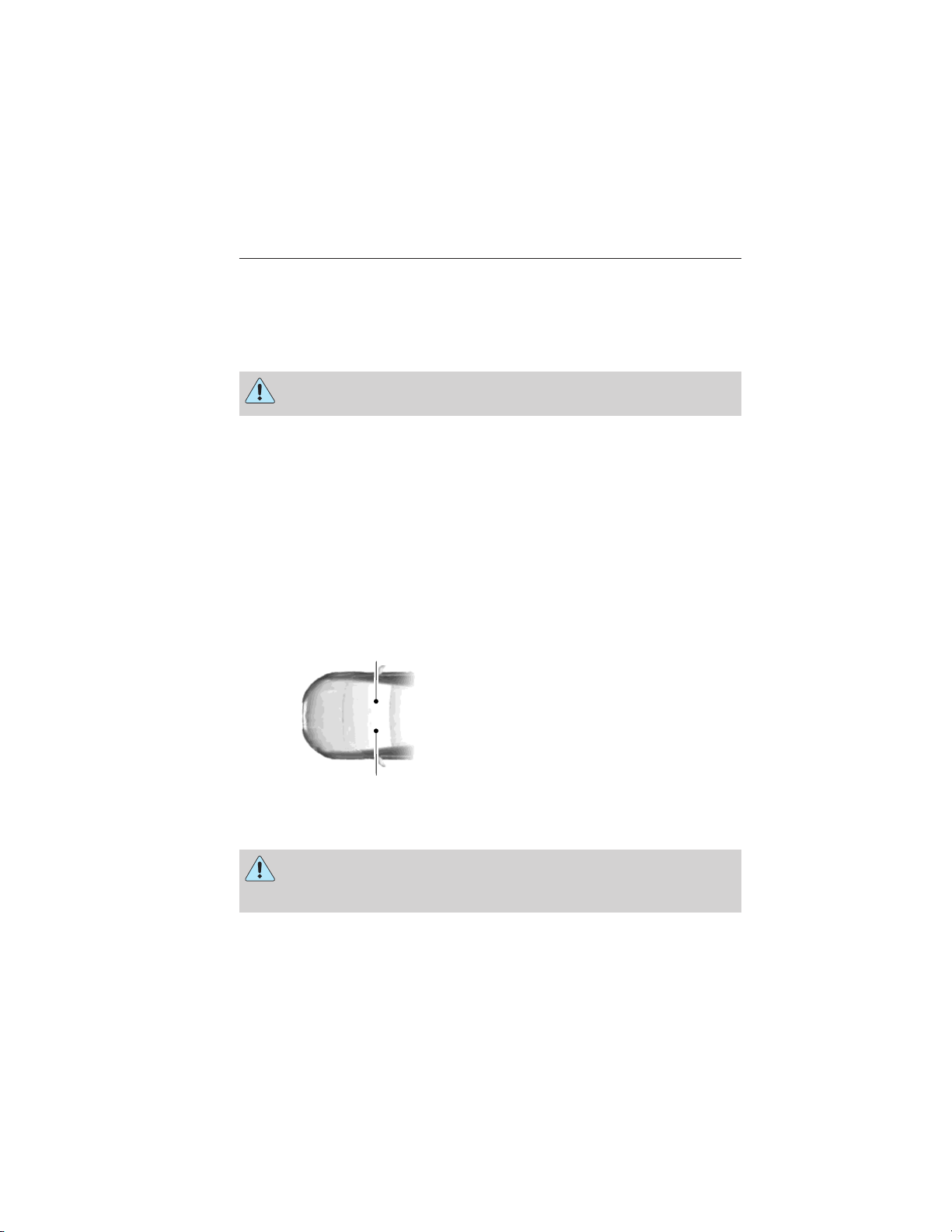
This manual may qualify the location of a component as left-hand side or
right-hand side. The side is determined when facing forward in the seat.
A
A. Right-hand side
B. Left-hand side
B
Symbols in this manual
WARNING: You risk death or serious injury to yourself and
others if you do not follow the instruction highlighted by the
warning symbol.
2015 Police (pol)
Owners Guide gf, 2nd Printing, April 2015
USA (fus)
Page 10
Introduction 9
Symbols on your vehicle
When you see these symbols, read and follow the relevant
instructions in this manual before touching or attempting
adjustment of any kind.
Protecting the Environment
You must play your part in protecting the environment. Correct
vehicle usage and the authorized disposal of waste, cleaning
and lubrication materials are significant steps toward this aim.
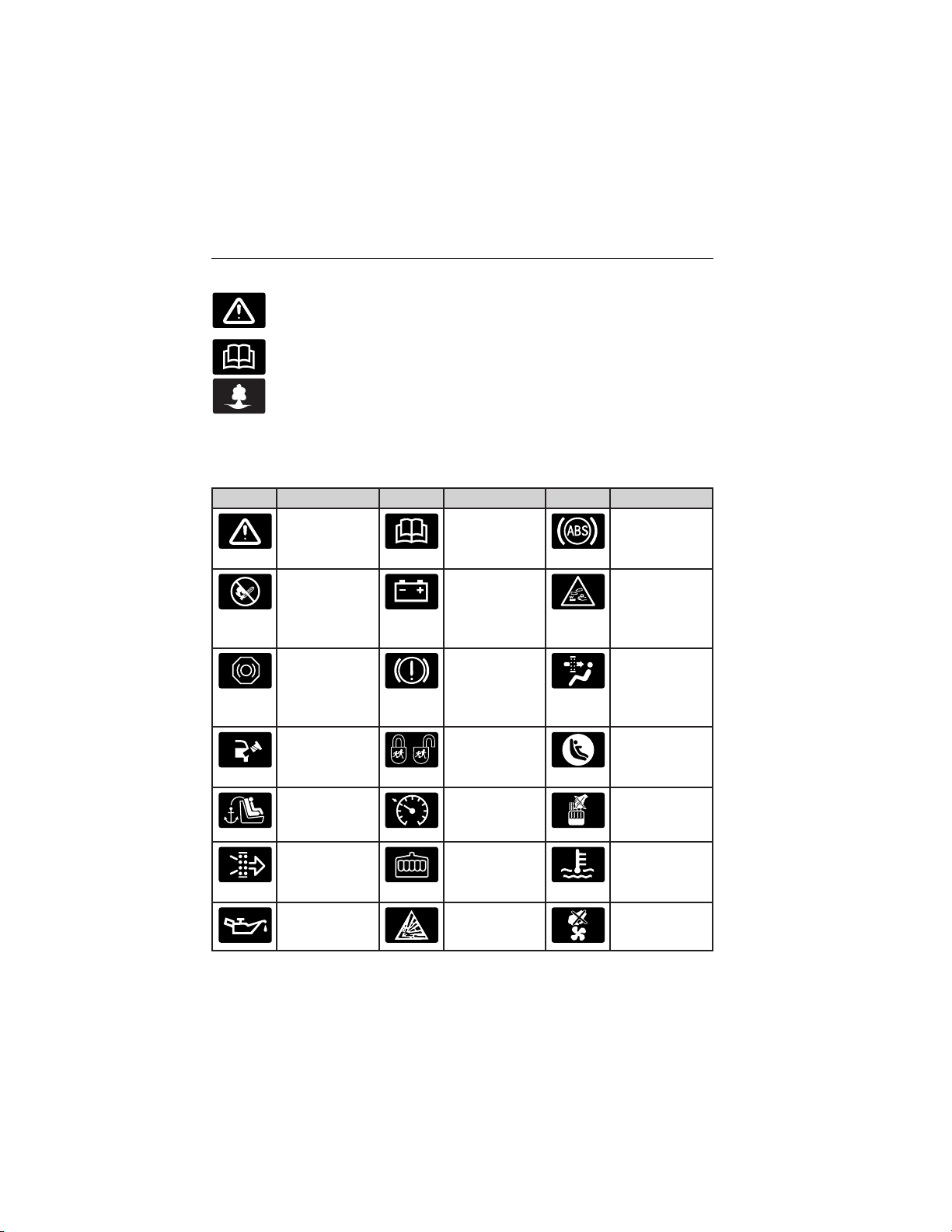
SYMBOL GLOSSARY
These are some of the symbols you may see on your vehicle.
Symbol Description Symbol Description Symbol Description
Safety alert See Owner’s
Manual
Avoid
smoking,
flames, or
sparks
Brake fluid –
non
petroleum
base
Check fuel
cap
Child seat
tether anchor
Battery Battery acid
Brake system Cabin air
Child Safety
Door Lock
and Unlock
Cruise
control
Anti-lock
braking
system
filter
Child seat
lower anchor
Do not open
when hot
Engine air
filter
Engine oil Explosive gas Fan warning
Engine
coolant
2015 Police (pol)
Owners Guide gf, 2nd Printing, April 2015
USA (fus)
Engine
coolant
temperature
Page 11
10 Introduction
Symbol Description Symbol Description Symbol Description
Fasten safety
belt
Front airbag Front fog
lamps
Fuel pump
reset
Heated rear
window
Lighting
control
Panic alarm Parking aid
Power
steering fluid
Service
engine soon
Windshield
defrost and
demist
Fuse
compartment
Interior
luggage
compartment
release
Low tire
pressure
warning
system
Power
windows
front and
rear
Side airbag Stability
Windshield
washer and
wiper
Hazard
warning
flasher
Jack
Maintain
correct fluid
level
Parking
brake system
Power
window
lockout
control
2015 Police (pol)
Owners Guide gf, 2nd Printing, April 2015
USA (fus)
Page 12

Introduction 11
DATA RECORDING
Service Data Recording
Service data recorders in your vehicle are capable of collecting and
storing diagnostic information about your vehicle. This potentially
includes information about the performance or status of various systems
and modules in the vehicle, such as engine, throttle, steering or brake
systems. In order to properly diagnose and service your vehicle, Ford
Motor Company, Ford of Canada, and service and repair facilities may
access or share among them vehicle diagnostic information received
through a direct connection to your vehicle when diagnosing or servicing
your vehicle. Additionally, when your vehicle is in for service or repair,
Ford Motor Company, Ford of Canada, and service and repair facilities
may access or share among them data for vehicle improvement purposes.
For U.S. only (if equipped), if you choose to use the SYNC® Vehicle
Health Report, you consent that certain diagnostic information may also
be accessed electronically by Ford Motor Company and Ford authorized
service facilities, and that the diagnostic information may be used for any
purpose. See the SYNC® chapter for more information.
Event Data Recording
This vehicle is equipped with an event data recorder (EDR). The
main purpose of an EDR is to record, in certain crash or near
crash-like situations, such as an airbag deployment or hitting a
road obstacle; this data will assist in understanding how a
vehicle’s systems performed. The EDR is designed to record data
related to vehicle dynamics and safety systems for a short period
of time, typically 30 seconds or less. The EDR in this vehicle is
designed to record such data as:
• How various systems in your vehicle were operating;
• Whether or not the driver and passenger safety belts were
buckled/fastened;
• How far (if at all) the driver was depressing the accelerator
and/or the brake pedal;
• How fast the vehicle was travelling;
• Where the driver was positioning the steering wheel.
This data can help provide a better understanding of the
circumstances in which crashes and injuries occur.
2015 Police (pol)
Owners Guide gf, 2nd Printing, April 2015
USA (fus)
Page 13

12 Introduction
Note: EDR data is recorded by your vehicle only if a non-trivial
crash situation occurs; no data is recorded by the EDR under normal
driving conditions and no personal data or information (e.g., name,
gender, age, and crash location) is recorded (see limitations
regarding 911 Assist and Traffic, Directions and Information privacy
below). However, parties, such as law enforcement, could combine
the EDR data with the type of personally identifying data routinely
acquired during a crash investigation.
To read data recorded by an EDR, special equipment is required,
and access to the vehicle or the EDR is needed. In addition to the
vehicle manufacturer, other parties, such as law enforcement,
that have such special equipment, can read the information if
they have access to the vehicle or the EDR. Ford Motor Company
and Ford of Canada do not access event data recorder
information without obtaining consent, unless pursuant to court
order or where required by law enforcement, other government
authorities or other third parties acting with lawful authority.
Other parties may seek to access the information independently
of Ford Motor Company and Ford of Canada.
Note: Including to the extent that any law pertaining to Event Data
Recorders applies to SYNC® or its features, please note the
following: Once 911 Assist (if equipped) is enabled (set ON), 911
Assist may, through any paired and connected cell phone, disclose
to emergency services that the vehicle has been in a crash involving
the deployment of an airbag or, in certain vehicles, the activation of
the fuel pump shut-off. Certain versions or updates to 911 Assist
may also be capable of being used to electronically or verbally
provide to 911 operators the vehicle location (such as latitude and
longitude), and/or other details about the vehicle or crash or
personal information about the occupants to assist 911 operators
to provide the most appropriate emergency services. If you do not
want to disclose this information, do not activate the 911 Assist
feature. See your SYNC® chapter for more information.
Additionally, when you connect to Traffic, Directions and
Information (if equipped, U.S. only), the service uses GPS
technology and advanced vehicle sensors to collect the vehicle’s
current location, travel direction, and speed (“vehicle travel
information”), only to help provide you with the directions,
traffic reports, or business searches that you request. If you do
not want Ford or its vendors to receive this information, do not
activate the service. For more information, see Traffic, Directions
and Information, Terms and Conditions. See your SYNC® chapter
for more information.
2015 Police (pol)
Owners Guide gf, 2nd Printing, April 2015
USA (fus)
Page 14

Introduction 13
CALIFORNIA PROPOSITION 65
WARNING: Some constituents of engine exhaust, certain vehicle
components, certain fluids contained in vehicles and certain
products of component wear contain or emit chemicals known to the
State of California to cause cancer and birth defects or other
reproductive harm.
PERCHLORATE MATERIAL
Note: Certain components in your vehicle, such as airbag modules,
safety belt pretensioners, and remote control batteries, may contain
perchlorate material. Special handling may apply for service or vehicle
end of life disposal. See www.dtsc.ca.gov/hazardouswaste/perchlorate for
more information.
FORD CREDIT (U.S. ONLY)
Ford Credit offers a full range of financing and lease plans to help you
acquire your vehicle. If you have financed or leased your vehicle through
Ford Credit, thank you for your business.
For your convenience, we offer a number of ways to contact us, as well
as help manage your account.
Phone: 1-800-727-7000
For more information regarding Ford Credit, as well as access to
Account Manager, please go to www.fordcredit.com.
REPLACEMENT PARTS RECOMMENDATION
Your vehicle has been built to the highest standards using quality parts.
We recommend that you demand the use of genuine Ford and Motorcraft
parts whenever your vehicle requires scheduled maintenance or repair.
You can clearly identify genuine Ford and Motorcraft parts by looking for
the Ford, FoMoCo or Motorcraft branding on the parts or their
packaging.
Scheduled Maintenance and Mechanical Repairs
One of the best ways for you to make sure that your vehicle provides
years of service is to have it maintained in line with our
recommendations using parts that conform to the specifications detailed
in this owner’s manual. Genuine Ford and Motorcraft parts meet or
exceed these specifications.
2015 Police (pol)
Owners Guide gf, 2nd Printing, April 2015
USA (fus)
Page 15

14 Introduction
Collision Repairs
We hope that you never experience a collision, but accidents do happen.
Genuine Ford replacement collision parts meet our stringent
requirements for fit, finish, structural integrity, corrosion protection and
dent resistance. During vehicle development, we validate that these parts
deliver the intended level of protection as a whole system. A great way
to know for sure you are getting this level of protection is to use genuine
Ford replacement collision parts.
Warranty on Replacement Parts
Genuine Ford and Motorcraft replacement parts are the only
replacement parts that benefit from a Ford Warranty. Damage caused to
your vehicle as a result of the failure of non-Ford parts may not be
covered by the Ford Warranty. For additional information, see the terms
and conditions of the Ford Warranty.
SPECIAL NOTICES
New Vehicle Limited Warranty
For a detailed description of what is covered and what is not covered by
your vehicle’s New Vehicle Limited Warranty, see the warranty
information that is provided to you along with your owner’s manual.
Special Instructions
For your added safety, your vehicle is fitted with sophisticated electronic
controls.
WARNING: Please read the Supplementary Restraints System
chapter. Failure to follow the specific warnings and instructions
could result in personal injury.
WARNING: Front seat mounted rear-facing child or infant seats
should NEVER be placed in front of an active passenger airbag.
2015 Police (pol)
Owners Guide gf, 2nd Printing, April 2015
USA (fus)
Page 16

Introduction 15
On-board Diagnostics (OBD-II)
Your vehicle’s On-board Diagnostics (OBD-II) system has a data port for
diagnostics, repair and reprogramming services with diagnostic scan
tools. Installing a non-Ford-approved aftermarket OBD plug-in device
that uses the port during normal driving, for example remote insurance
company monitoring, remote vehicle diagnostics, telematics or engine
reprogramming, may cause interference or damage to vehicle systems.
We do not recommend or endorse the use of any non-Ford-approved
aftermarket OBD plug-in devices. The vehicle Warranty may not cover
damage caused by any non-Ford-approved aftermarket OBD plug-in
device.
Notice to owners of pickup trucks and utility type vehicles
WARNING: Utility vehicles have a significantly higher rollover
rate than other types of vehicles.
Before you drive your vehicle, please read this Owner’s Manual carefully.
Your vehicle is not a passenger car. As with other vehicles of this type,
failure to operate your vehicle correctly may result in loss of vehicle
control, vehicle rollover, personal injury or death.
Using your vehicle with a snowplow
Do not use this vehicle for snowplowing.
Your vehicle is not equipped with a snowplowing package.
Using your vehicle as an ambulance
Do not use this vehicle as an ambulance.
Your vehicle is not equipped with the Ford Ambulance Preparation
Package.
My Fleet Management (If Equipped)
This feature allows a fleet administrator to control specific vehicle
settings using a Ford authorized service tool. This helps the fleet
administrator set certain vehicle settings to match administrative policy.
The configurable settings are:
• Vehicle Speed– Select an alternative speed limit that is below your
vehicle’s maximum capability. A message displays and a chime sounds
when starting your vehicle to indicate the customized speed limit.
• Audio Volume– Select a limit for the maximum volume of the audio
system in the range of 0% (full mute) to 100% (no limit) in 10%
increments.
2015 Police (pol)
Owners Guide gf, 2nd Printing, April 2015
USA (fus)
Page 17

16 Introduction
MOBILE COMMUNICATIONS EQUIPMENT
Using mobile communications equipment is becoming increasingly
important in the conduct of business and personal affairs. However, you
must not compromise your own or others’ safety when using such
equipment. Mobile communications can enhance personal safety and
security when appropriately used, particularly in emergency situations.
Safety must be paramount when using mobile communications
equipment to avoid negating these benefits.
Mobile communication equipment includes, but is not limited to, cellular
phones, pagers, portable email devices, text messaging devices and
portable two-way radios.
WARNING: Driving while distracted can result in loss of vehicle
control, crash and injury. We strongly recommend that you use
extreme caution when using any device that may take your focus off
the road. Your primary responsibility is the safe operation of your
vehicle. We recommend against the use of any handheld device while
driving and encourage the use of voice-operated systems when possible.
Make sure you are aware of all applicable local laws that may affect the
use of electronic devices while driving.
EXPORT UNIQUE (NON–UNITED STATES/CANADA) VEHICLE SPECIFIC INFORMATION
For your particular global region, your vehicle may be equipped with
features and options that are different from the features and options that
are described in this owner’s manual. A market unique supplement may
be supplied that complements this book. By referring to the market
unique supplement, if provided, you can properly identify those features,
recommendations and specifications that are unique to your vehicle. This
owner’s manual is written primarily for the U.S. and Canadian Markets.
Features or equipment listed as standard may be different on units built
for Export. See this owner’s manual for all other required
information and warnings.
2015 Police (pol)
Owners Guide gf, 2nd Printing, April 2015
USA (fus)
Page 18

Child Safety 17
GENERAL INFORMATION
See the following sections for directions on how to properly use safety
restraints for children.
WARNING: Always make sure your child is secured properly in a
device that is appropriate for their height, age and weight. Child
safety restraints must be bought separately from your vehicle. Failure
to follow these instructions and guidelines may result in an increased
risk of serious injury or death to your child.
WARNING: All children are shaped differently. The
recommendations for safety restraints are based on probable
child height, age and weight thresholds from NHTSA and other safety
organizations, or are the minimum requirements of law. Ford
recommends checking with a NHTSA Certified Child Passenger Safety
Technician (CPST) and consulting your pediatrician to make sure your
child seat is appropriate for your child, and is compatible with and
properly installed in your vehicle. To locate a child seat fitting station
and CPST, contact the NHTSA toll free at 1-888-327-4236 or on the
internet at http://www.nhtsa.dot.gov. In Canada, check with your local
St. John Ambulance office for referral to a CPST or for further
information, contact your provincial ministry of transportation, or locate
your local St. John Ambulance office by searching for St. John
Ambulance on the internet, or Transport Canada at 1–800–333–0371
(http://www.tc.gc.ca). Failure to properly restrain children in safety
seats made especially for their height, age, and weight may result in an
increased risk of serious injury or death to your child.
WARNING: Do not leave children or animals unattended in the
vehicle. On hot days, the temperature in the trunk or vehicle
interior can rise very quickly. Exposure of people or animals to these
high temperatures for even a short time can cause death or serious
heat-related injuries, including brain damage. Small children are
particularly at risk.
2015 Police (pol)
Owners Guide gf, 2nd Printing, April 2015
USA (fus)
Page 19

18 Child Safety
Recommendations for Safety Restraints for Children
Child size, height, weight, or age
Infants
or
toddlers
Small
children
Larger
children
• You are required by law to properly use safety seats for infants and
toddlers in the United States and Canada.
• Many states and provinces require that small children use approved
booster seats until they reach age eight, a height of 4 feet 9 inches
(1.45 meters) tall, or 80 pounds (36 kilograms). Check your local and
state or provincial laws for specific requirements about the safety of
children in your vehicle.
• When possible, always properly restrain children twelve (12) years of
age and under in a rear seating position of your vehicle. Accident
statistics suggest that children are safer when properly restrained in
the rear seating positions than in a front seating position. See Front
Passenger Sensing System in the Supplementary Restraints System
chapter for more information.
Children weighing 40 lb (18 kg) or less
(generally age four or younger).
Children who have outgrown or no
longer properly fit in a child safety seat
(generally children who are less than
4 ft. 9 in. (1.45 m) tall, are greater than
age four (4) and less than age twelve
(12), and between 40 lb (18 kg) and
80 lb (36 kg) and upward to 100 lb
(45 kg) if recommended by your child
restraint manufacturer).
Children who have outgrown or no
longer properly fit in a belt-positioning
booster seat (generally children who are
at least 4 ft. 9 in. (1.45 m) tall or greater
than 80 lb (36 kg) or 100 lb (45 kg) if
recommended by child restraint
manufacturer).
Recommended
restraint type
Use a child safety
seat (sometimes
called an infant
carrier, convertible
seat, or toddler
seat).
Use a
belt-positioning
booster seat.
Use a vehicle
safety belt having
the lap belt snug
and low across the
hips, shoulder belt
centered across
the shoulder and
chest, and seat
back upright.
2015 Police (pol)
Owners Guide gf, 2nd Printing, April 2015
USA (fus)
Page 20

Child Safety 19
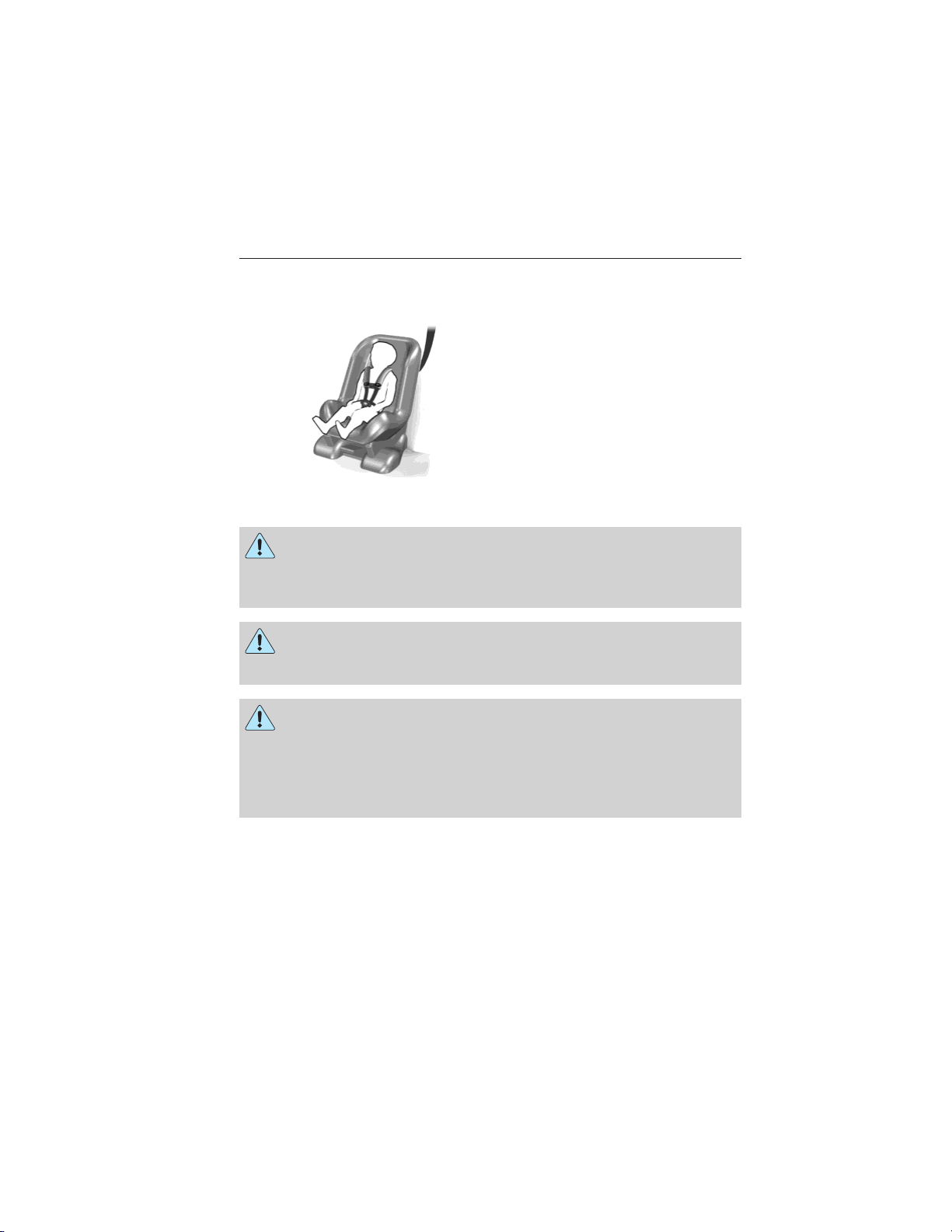
CHILD SEAT POSITIONING
WARNING: Airbags can kill or injure a child in a child seat.
Never place a rear-facing child seat in front of an active airbag. If
you must use a forward-facing child seat in the front seat, move the
vehicle seat upon which the child seat is installed all the way back.
When possible, all children age 12 and under should be properly
restrained in a rear seating position. If all children cannot be seated and
restrained properly in a rear seating position, properly restrain the
largest child in the front seat.
WARNING: Always carefully follow the instructions and
warnings provided by the manufacturer of any child restraint to
determine if the restraint device is appropriate for your child’s size,
height, weight, or age. Follow the child restraint manufacturer’s
instructions and warnings provided for installation and use in
conjunction with the instructions and warnings provided by your
vehicle manufacturer. A safety seat that is improperly installed or
utilized, is inappropriate for your child’s height, age or weight, or does
not properly fit the child, may increase the risk of serious injury or
death.
WARNING: Never let a passenger hold a child on his or her lap
while your vehicle is moving. The passenger cannot protect the
child from injury in a crash, which may result in serious injury or death.
WARNING: Never use pillows, books, or towels to boost a child.
They can slide around and increase the likelihood of injury or
death in a crash.
WARNING: Always restrain an unoccupied child seat or booster
seat. These objects may become projectiles in a crash or sudden
stop, which may increase the risk of serious injury.
2015 Police (pol)
Owners Guide gf, 2nd Printing, April 2015
USA (fus)
Page 21
20 Child Safety
WARNING: Never place, or allow a child to place, the shoulder
belt under a child’s arm or behind the back because it reduces
the protection for the upper part of the body and may increase the risk
of injury or death in a crash.
WARNING: To avoid risk of injury, do not leave children or pets
unattended in your vehicle.
Recommendations for attaching child safety restraints for
children
Use any attachment method as indicated
Restraint
Type
Rear-facing
child seat
Rear-facing
child seat
Forward-facing
child seat
Forward-facing
child seat
Combined
weight of
child and
child seat
Up to
65 lb
(29.5 kg)
Over 65 lb
(29.5 kg)
Up to
65 lb
(29.5 kg)
Over 65 lb
(29.5 kg)
LATCH
(lower
anchors
and top
tether
anchor)
LATCH
(lower
anchors
only)
XXX
Note: The child seat must rest tightly against the vehicle seat upon
which it is installed. It may be necessary to lift or remove the head
restraint. See the Seats chapter for information on head restraints.
below by X.
Safety
belt
and
top
tether
anchor
XX
Safety
belt and
LATCH
(lower
anchors
and top
tether
anchor)
XX
Safety
belt
only
X
2015 Police (pol)
Owners Guide gf, 2nd Printing, April 2015
USA (fus)
Page 22
Child Safety 21
BOOSTER SEATS
WARNING: Never place, or allow a child to place, the shoulder
belt under a child’s arm or behind the back because it reduces
the protection for the upper part of the body and may increase the risk
of injury or death in a crash.
Use a belt-positioning booster seat for children who have outgrown or no
longer properly fit in a child safety seat (generally children who are less
than 4 feet 9 inches (1.45 meters) tall, are greater than age four (4) and
less than age twelve (12), and between 40 pounds (18 kilograms) and
80 pounds (36 kilograms) and upward to 100 pounds (45 kilograms) if
recommended by your child restraint manufacturer). Many state and
provincial laws require that children use approved booster seats until
they reach age eight, a height of 4 feet 9 inches (1.45 meters) tall, or
80 pounds (36 kilograms).
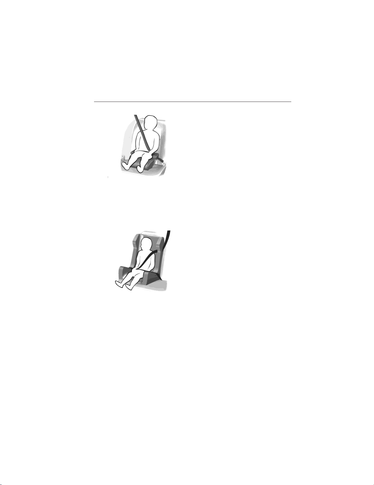
Booster seats should be used until you can answer YES to ALL of these
questions when seated without a booster seat.
• Can the child sit all the way
back against their vehicle seat
with knees bent comfortably at
the edge of the seat cushion?
• Can the child sit without
slouching?
• Does the lap belt rest low across the hips?
• Is the shoulder belt centered on the shoulder and chest?
• Can the child stay seated like this for the whole trip?
Always use booster seats in conjunction with your vehicle lap and
shoulder belt.
2015 Police (pol)
Owners Guide gf, 2nd Printing, April 2015
USA (fus)
Page 23
22 Child Safety
Types of Booster Seats
• Backless booster seats
If your backless booster seat has a removable shield, remove the shield.
If a vehicle seating position has a low seatback or no head restraint, a
backless booster seat may place your child’s head (as measured at the
tops of the ears) above the top of the seat. In this case, move the
backless booster to another seating position with a higher seatback or
head restraint and lap and shoulder belts, or consider using a high back
booster seat.
• High back booster seats
If, with a backless booster seat, you cannot find a seating position that
adequately supports your child’s head, a high back booster seat would be
a better choice.
2015 Police (pol)
Owners Guide gf, 2nd Printing, April 2015
USA (fus)
Page 24
Child Safety 23
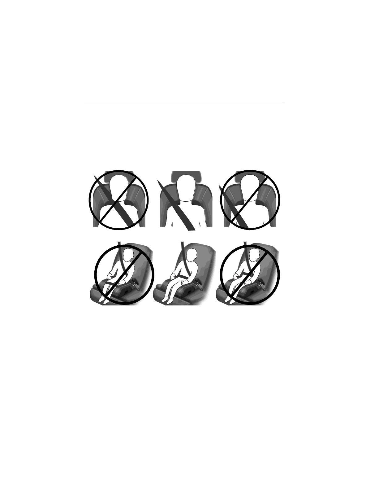
Children and booster seats vary in size and shape. Choose a booster that
keeps the lap belt low and snug across the hips, never up across the
stomach, and lets you adjust the shoulder belt to cross the chest and
rest snugly near the center of the shoulder. The following drawings
compare the ideal fit (center) to a shoulder belt uncomfortably close to
the neck and a shoulder belt that could slip off the shoulder. The
drawings also show how the lap belt should be low and snug across the
child’s hips.
If the booster seat slides on the vehicle seat upon which it is being used,
placing a rubberized mesh sold as shelf or carpet liner under the booster
seat may improve this condition. Do not introduce any item thicker than
this under the booster seat. Check with the booster seat manufacturer’s
instructions.
2015 Police (pol)
Owners Guide gf, 2nd Printing, April 2015
USA (fus)
Page 25
24 Child Safety
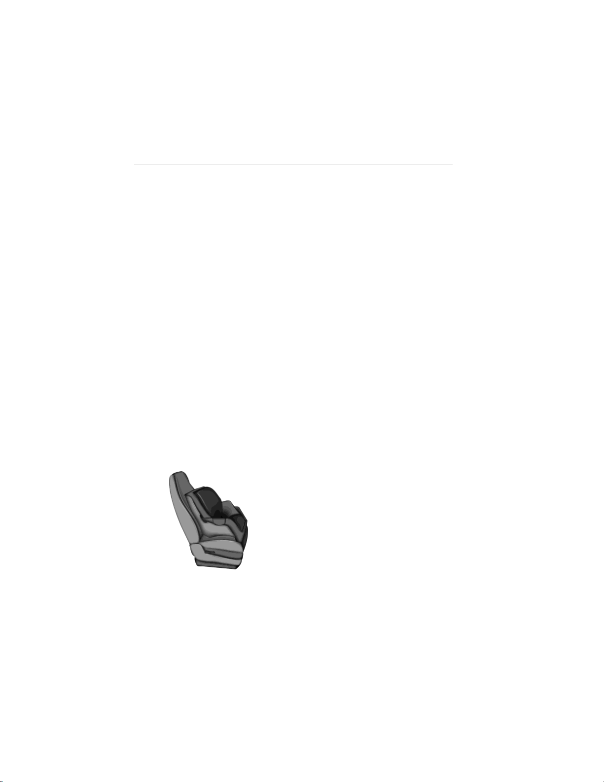
INSTALLING CHILD SEATS
Child Seats
Use a child safety seat (sometimes
called an infant carrier, convertible
seat, or toddler seat) for infants,
toddlers or children weighing
40 pounds (18 kilograms) or less
(generally age four or younger).
Using Lap and Shoulder Belts
WARNING: Airbags can kill or injure a child in a child seat.
Never place a rear-facing child seat in front of an active airbag. If
you must use a forward-facing child seat in the front seat, move the
seat upon which the child seat is installed all the way back.
WARNING: Airbags can kill or injure a child in a child seat.
Children 12 and under should be properly restrained in the rear
seat whenever possible.
WARNING: Depending on where you secure a child restraint,
and depending on the child restraint design, you may block
access to certain safety belt buckle assemblies or LATCH lower
anchors, rendering those features potentially unusable. To avoid risk of
injury, occupants should only use seating positions where they are able
to be properly restrained.
2015 Police (pol)
Owners Guide gf, 2nd Printing, April 2015
USA (fus)
Page 26
Child Safety 25
When installing a child safety seat with combination lap and shoulder
belts:
• Use the correct safety belt buckle for that seating position.
• Insert the belt tongue into the proper buckle until you hear a snap
and feel it latch. Make sure the tongue is securely fastened in the
buckle.
• Keep the buckle release button pointing up and away from the safety
seat, with the tongue between the child seat and the release button,
to prevent accidental unbuckling.
• Place the vehicle seat upon which the child seat will be installed in
the upright position.
• For second row seating positions, if needed, the recliner may be
adjusted slightly to improve child seat fit. If needed, the head
restraints may be removed.
• Put the safety belt in the automatic locking mode. See Step 5. This
vehicle does not require the use of a locking clip.
Perform the following steps when installing the child seat with
combination lap and shoulder belts:
Note: Although the child seat illustrated is a forward facing child seat,
the steps are the same for installing a rear facing child seat.
Note: Follow all instructions provided by the manufacturer of the child
restraint regarding the necessary and proper use of the Lock-off device.
In some instances these devices have been provided only for use in
vehicles with safety belt systems that would otherwise require a locking
clip. This vehicle does not require the use of a locking clip.
1. Position the child safety seat in a
seat with a combination lap and
shoulder belt.
2015 Police (pol)
Owners Guide gf, 2nd Printing, April 2015
USA (fus)
Page 27
26 Child Safety
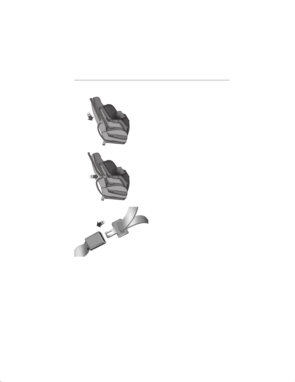
2. After positioning the child safety seat in the proper seating position,
do the following:
Pull down on the shoulder belt and
then grasp the shoulder belt and lap
belt together behind the belt
tongue.
3. While holding the shoulder and
lap belt portions together, route the
tongue through the child seat
according to the child seat
manufacturer’s instructions. Be sure
the belt webbing is not twisted.
4. Insert the belt tongue into the
proper buckle (the buckle closest to
the direction the tongue is coming
from) for that seating position until
you hear a snap and feel the latch
engage. Make sure the tongue is
latched securely by pulling on it.
2015 Police (pol)
Owners Guide gf, 2nd Printing, April 2015
USA (fus)
Page 28
Child Safety 27
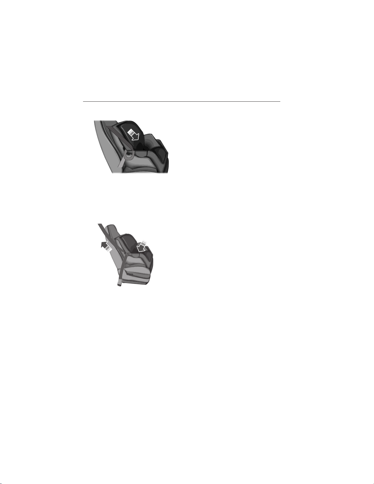
5. To put the retractor in the automatic locking mode, do the following;
Grasp the shoulder portion of the
belt and pull downward until all of
the belt is pulled out.
6. Allow the belt to retract to remove slack. The belt will click as it
retracts to indicate it is in the automatic locking mode.
7. Try to pull the belt out of the retractor to make sure the retractor is
in the automatic locking mode (you should not be able to pull more belt
out). If the retractor is not locked, repeat Steps 5 and 6.
8. Remove remaining slack from the
belt. Force the seat down with extra
weight, for example, by pressing
down or kneeling on the child
restraint while pulling up on the
shoulder belt in order to force slack
from the belt. This is necessary to
remove the remaining slack that will
exist once the extra weight of the
child is added to the child restraint.
It also helps to achieve the proper
snugness of the child seat to your vehicle. Sometimes, a slight lean
toward the buckle will provide extra help to remove remaining slack
from the belt.
9. Attach the tether strap (if the child seat is equipped). See Using
Tether Straps later in this chapter.
2015 Police (pol)
Owners Guide gf, 2nd Printing, April 2015
USA (fus)
Page 29
28 Child Safety
10. Before placing the child in the
seat, forcibly move the seat forward
and back to make sure the seat is
securely held in place. To check
this, grab the seat at the belt path
and attempt to move it side to side
and forward and back. There should
be no more than 1 inch (2.5
centimeters) of movement for
proper installation.
Ford recommends checking with a NHTSA Certified Child Passenger
Safety Technician to make certain the child restraint is properly installed.
In Canada, check with your local St. John Ambulance office for referral
to a Child Passenger Safety Technician.
Using Lower Anchors and Tethers for CHildren (LATCH)
WARNING: Never attach two child safety seats to the same
anchor. In a crash, one anchor may not be strong enough to hold
two child safety seat attachments and may break, causing serious injury
or death.
WARNING: Depending on where you secure a child restraint,
and depending on the child restraint design, you may block
access to certain safety belt buckle assemblies or LATCH lower
anchors, rendering those features potentially unusable. To avoid risk of
injury, occupants should only use seating positions where they are able
to be properly restrained.
The LATCH system is composed of three vehicle anchor points: two lower
anchors located where seat back and seat cushion meet (called the seat
bight) and one top tether anchor located behind that seating position.
LATCH compatible child safety seats have two rigid or webbing mounted
attachments that connect to the two lower anchors at the LATCH
equipped seating positions in your vehicle. This type of attachment
method eliminates the need to use safety belts to attach the child seat,
however the safety belt can still be used to attach the child seat. For
forward-facing child seats, the top tether strap must also be attached to
the proper top tether anchor, if a top tether strap has been provided
with your child seat.
2015 Police (pol)
Owners Guide gf, 2nd Printing, April 2015
USA (fus)
Page 30
Child Safety 29
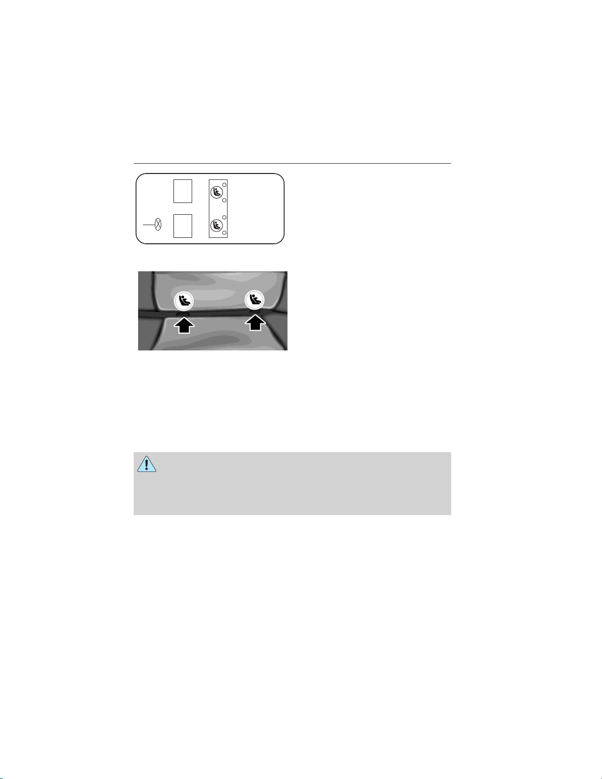
Your vehicle has LATCH lower
anchors for child seat installation at
the seating positions marked with
the child seat symbol.
The LATCH anchors are located at
the rear section of the rear seat
between the cushion and seat back
below the symbols as shown. Follow
the child seat manufacturer’s
instructions to properly install a
child seat with LATCH attachments.
Follow the instructions on attaching child safety seats with tether straps.
See Using Tether Straps later in this chapter.
Attach LATCH lower attachments of the child seat only to the anchors
shown.
Use of inboard lower anchors from the outboard seating positions (center seating use) (sedan vehicles)
WARNING: The standardized spacing for LATCH lower anchors
is 11 inches (28 centimeters) center to center. Do not use
LATCH lower anchors for the center seating position unless the child
seat manufacturer’s instructions permit and specify using anchors
spaced at least as far apart as those in this vehicle.
Child seat positioning for LATCH lower anchors
All the LATCH lower anchors are equally spaced, 11 inches (28
centimeters) apart, allowing for the following child seat positioning:
• If a single child seat is installed using the LATCH lower anchors, it can
be installed at any rear seating position.
• If two child safety seats are installed using the LATCH lower anchors,
they must be placed in the outboard seating positions only.
2015 Police (pol)
Owners Guide gf, 2nd Printing, April 2015
USA (fus)
Page 31

30 Child Safety
• Or you can use the LATCH lower anchors for the center child safety
seat and the lap and shoulder belts for the other two child safety seats
in the outboard positions. Use the tether anchors if applicable. If three
child safety seats are installed, you can install two using the LATCH
lower anchors by placing them in each outboard seating position and
the third in the center using the lap and shoulder belt.
Each time you use the safety seat, check that the seat is properly
attached to the lower anchors and tether anchor, if applicable. Tug the
child seat from side to side and forward and back where it is secured to
your vehicle. The seat should move less than one inch when you do this
for a proper installation.
If the safety seat is not anchored properly, the risk of a child being
injured in a crash greatly increases.
Use of inboard lower anchors from the outboard seating positions (center seating use) (utility vehicles)
WARNING: The standardized spacing for LATCH lower anchors
is 11 inches (28 centimeters) center to center. Do not use
LATCH lower anchors for the center seating position unless the child
seat manufacturer’s instructions permit and specify using anchors
spaced at least as far apart as those in this vehicle.
The lower anchors at the center of the second row bench seats are
spaced 20.5 inches (52 centimeters) apart. The standardized spacing for
LATCH lower anchors is 11 inches (28 centimeters) center to center. A
child seat with rigid LATCH attachments cannot be installed at the
center seating position. LATCH compatible child seats (with attachments
on belt webbing) can only be used at this seating position provided that
the child seat manufacturer’s instructions permit use with the anchor
spacing stated. Do not attach a child seat to any lower anchor if an
adjacent child seat is attached to that anchor.
Each time you use the safety seat, check that the seat is properly
attached to the lower anchors and tether anchor, if applicable. Tug the
child seat from side to side and forward and back where it is secured to
your vehicle. The seat should move less than one inch when you do this
for a proper installation.
If the safety seat is not anchored properly, the risk of a child being
injured in a crash greatly increases.
2015 Police (pol)
Owners Guide gf, 2nd Printing, April 2015
USA (fus)
Page 32

Child Safety 31
Combining Safety Belt and LATCH Lower Anchors for Attaching Child Safety Seats
When used in combination, either the safety belt or the LATCH lower
anchors may be attached first, provided a proper installation is achieved.
Attach the tether strap afterward, if included with the child seat.
Using Tether Straps
Many forward-facing child safety seats include a tether strap
which extends from the back of the child safety seat and hooks
to an anchoring point called the top tether anchor. Tether
straps are available as an accessory for many older safety seats.
Contact the manufacturer of your child seat for information about
ordering a tether strap, or to obtain a longer tether strap if the tether
strap on your safety seat does not reach the appropriate top tether
anchor in your vehicle.
Once the child safety seat has been installed using either the safety belt,
the lower anchors of the LATCH system, or both, you can attach the top
tether strap.
The tether strap anchors in your vehicle are in the following positions
(shown from top view):
• Second row seats
Perform the following steps to install a child safety seat with tether
anchors:
Note: If you install a child seat with rigid LATCH attachments, do not
tighten the tether strap enough to lift the child seat off your vehicle seat
cushion when the child is seated in it. Keep the tether strap just snug
without lifting the front of the child seat. Keeping the child seat just
touching your vehicle seat gives the best protection in a severe crash.
2015 Police (pol)
Owners Guide gf, 2nd Printing, April 2015
USA (fus)
Page 33

32 Child Safety
Sedan
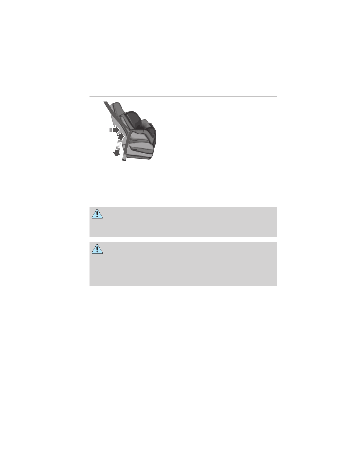
1. Route the child safety seat tether strap over the back of the seat.
2. Locate the correct anchor for the
selected seating position.
3. Open the tether anchor cover.
4. Clip the tether strap to the
anchor as shown.
5. Tighten the child safety seat tether strap according to the
manufacturer’s instructions.
2015 Police (pol)
Owners Guide gf, 2nd Printing, April 2015
USA (fus)
Page 34

Child Safety 33
Utility
1. Route the child safety seat tether strap over the seat back.
2. Locate the correct anchor for the selected rear seating position:
3. Clip the tether hook to the
anchor as shown.
The tether hook may be twisted 1/2 turn to improve installation. If the
tether strap is clipped incorrectly, the child safety seat may not be
retained properly in the event of a crash.
4. Tighten the child safety seat tether strap according to the
manufacturer’s instructions.
If the safety seat is not anchored properly, the risk of a child being
injured in a crash greatly increases.
If your child restraint system is equipped with a tether strap, and the
child restraint manufacturer recommends its use, Ford also recommends
its use.
2015 Police (pol)
Owners Guide gf, 2nd Printing, April 2015
USA (fus)
Page 35

34 Child Safety
CHILD SAFETY LOCKS
When these locks are set, the rear doors cannot be opened from the
inside.
The childproof locks are located on
the rear edge of each rear door and
must be set separately for each
door.
• Insert the key and turn to the
lock position (key horizontal) to
engage the childproof locks.
• Insert the key and turn to the
unlock position (key vertical) to
disengage the childproof locks.
2015 Police (pol)
Owners Guide gf, 2nd Printing, April 2015
USA (fus)
Page 36

Safety Belts 35
PRINCIPLES OF OPERATION
WARNING: Never let a passenger hold a child on his or her lap
while your vehicle is moving. The passenger cannot protect the
child from injury in a crash.
WARNING: It is extremely dangerous to ride in a cargo area,
inside or outside of a vehicle. In a crash, people riding in these
areas are more likely to be seriously injured or killed. Do not allow
people to ride in any area of your vehicle that is not equipped with
seats and safety belts. Be sure everyone in your vehicle is in a seat and
using a safety belt properly.
WARNING: Always drive and ride with your seatback upright
and the lap belt snug and low across the hips.
WARNING: To reduce the risk of injury, make sure children sit
where they can be properly restrained.
WARNING: All occupants of your vehicle, including the driver,
should always properly wear their safety belts, even when an
airbag supplemental restraint system is provided. Failure to properly
wear your safety belt could seriously increase the risk of injury or
death.
WARNING: In a rollover crash, an unbelted person is
significantly more likely to die than a person wearing a safety
belt.
WARNING: Each seating position in your vehicle has a specific
safety belt assembly which is made up of one buckle and one
tongue that are designed to be used as a pair. 1) Use the shoulder belt
on the outside shoulder only. Never wear the shoulder belt under the
arm. 2) Never swing the safety belt around your neck over the inside
shoulder. 3) Never use a single belt for more than one person.
2015 Police (pol)
Owners Guide gf, 2nd Printing, April 2015
USA (fus)
Page 37

36 Safety Belts
WARNING: When possible, all children 12 years old and under
should be properly restrained in a rear seating position. Failure
to follow this could seriously increase the risk of injury or death.
WARNING: Safety belts and seats can become hot in a vehicle
that has been closed up in sunny weather; they could burn a
small child. Check seat covers and buckles before you place a child
anywhere near them.
WARNING: Front and rear seat occupants, including pregnant
women, should wear safety belts for optimum protection in an
accident.
All seating positions in your vehicle have lap and shoulder safety belts.
All occupants of the vehicle should always properly wear their safety
belts, even when an airbag supplemental restraint system is provided.
The safety belt system consists of:
• Lap and shoulder safety belts.
• Shoulder safety belt with automatic locking mode (except driver
safety belt).
• Height adjuster at the front outboard seating positions (utility only).
• Safety belt pretensioner at the front outboard seating positions.
• Belt tension sensor at the front outboard passenger seating position.
• Safety belt warning light and chime. See Safety belt warning
light and indicator chime later in this chapter.
• Crash sensors and monitoring system with readiness
indicator. See Crash sensors and airbag indicator in the
Supplemental Restraint System chapter.
The safety belt pretensioners are designed to activate in frontal,
near-frontal and side crashes, and in rollovers. The safety belt
pretensioners at the front seating positions are designed to tighten the
safety belts firmly against the occupant’s body when activated. This helps
increase the effectiveness of the safety belts. In frontal crashes, the
safety belt pretensioners can be activated alone or, if the crash is of
sufficient severity, together with the front airbags.
2015 Police (pol)
Owners Guide gf, 2nd Printing, April 2015
USA (fus)
Page 38

Safety Belts 37
FASTENING THE SAFETY BELTS
The front outboard and rear safety restraints in your vehicle are
combination lap and shoulder belts.
1. Insert the belt tongue into the
proper buckle (the buckle closest to
the direction the tongue is coming
from) until you hear a snap and feel
it latch. Make sure the tongue is
securely fastened in the buckle.
2. To unfasten, press the release
button and remove the tongue from
the buckle.
Using Safety Belts During Pregnancy
WARNING: Always ride and drive with your seatback upright
and the safety belt properly fastened. The lap portion of the
safety belt should fit snug and be positioned low across the hips. The
shoulder portion of the safety belt should be positioned across the
chest. Pregnant women should also follow this practice. See the
following figure.
2015 Police (pol)
Owners Guide gf, 2nd Printing, April 2015
USA (fus)
Page 39

38 Safety Belts
Pregnant women should always
wear their safety belts. The lap belt
portion of a combination lap and
shoulder belt should be positioned
low across the hips below the belly
and worn as tight as comfort will
allow. The shoulder belt should be
positioned to cross the middle of
the shoulder and the center of the
chest.
Safety Belt Locking Modes
WARNING: After any vehicle crash, the safety belt system at all
passenger seating positions must be checked by an authorized
dealer to verify that the automatic locking retractor feature for child
seats is still functioning properly. In addition, all safety belts should be
checked for proper function.
WARNING: The belt and retractor assembly must be replaced if
the safety belt assembly automatic locking retractor feature or
any other safety belt function is not operating properly when checked
by an authorized dealer. Failure to replace the belt and retractor
assembly could increase the risk of injury in crashes.
All safety restraints in the vehicle are combination lap and shoulder
belts. The driver safety belt has the first type of locking mode. The front
outboard passenger and rear seat safety belts have both types of locking
modes described as follows:
Vehicle Sensitive Mode
This is the normal retractor mode, which allows free shoulder belt length
adjustment to your movements and locking in response to vehicle
movement. For example, if the driver brakes suddenly or turns a corner
sharply, or the vehicle receives an impact of about 5 mph (8 km/h) or
more, the combination safety belts will lock to help reduce forward
movement of the driver and passengers.
In addition, the retractor is designed to lock if the webbing is pulled out
too quickly. If this occurs, let the belt retract slightly and pull webbing
out again in a slow and controlled manner.
2015 Police (pol)
Owners Guide gf, 2nd Printing, April 2015
USA (fus)
Page 40

Safety Belts 39
Automatic Locking Mode
In this mode, the shoulder belt is automatically pre-locked. The belt will
still retract to remove any slack in the shoulder belt. The automatic
locking mode is not available on the driver safety belt.
When to Use the Automatic Locking Mode
This mode should be used any time a child safety seat, except a booster,
is installed in passenger front or rear seating positions. Children 12 years
old and under should be properly restrained in a rear seating position
whenever possible. See the Child Safety chapter.
How to Use the Automatic Locking Mode
1. Buckle the combination lap and shoulder
belt.
2. Grasp the shoulder portion and pull
downward until the entire belt is pulled out.
3. Allow the belt to retract. As the belt
retracts, you will hear a clicking sound. This
indicates the safety belt is now in the
automatic locking mode.
How to Disengage the Automatic Locking Mode
Unbuckle the combination lap and shoulder belt and allow it to retract
completely to disengage the automatic locking mode and activate the
vehicle sensitive (emergency) locking mode.
Safety Belt Extension Assembly
WARNING: Do not use extensions to change the fit of the
shoulder belt across the torso.
If the safety belt is too short when fully extended, you can obtain a
safety belt extension assembly from an authorized dealer.
Use only extensions manufactured by the same supplier as the safety
belt. Manufacturer identification is on a label located either at the end of
the webbing or on the retractor behind the trim. Also, use the safety belt
extension only if the safety belt is too short for you when fully extended.
2015 Police (pol)
Owners Guide gf, 2nd Printing, April 2015
USA (fus)
Page 41

40 Safety Belts
SAFETY BELT HEIGHT ADJUSTMENT (UTILITY)
WARNING: Position the safety belt height adjusters so that the
belt rests across the middle of your shoulder. Failure to adjust
the safety belt properly could reduce the effectiveness of the seat belt
and increase the risk of injury in a crash.
Your vehicle has safety belt height adjustments for the front outboard
seating positions.
1. Adjust the height of the shoulder
belt so the belt rests across the
middle of your shoulder.
2. Slide the adjuster up to raise the
belt. Push the button and slide it
down to lower the belt.
SAFETY BELT WARNING LIGHT AND INDICATOR CHIME
This lamp illuminates and an audible warning will sound if the
driver’s safety belt has not been fastened when the vehicle’s
ignition is turned on.
Conditions of Operation
If... Then...
The driver safety belt is not
buckled before the ignition
switch is turned to the on
position...
The driver safety belt is
buckled while the indicator
light is illuminated and the
warning chime is sounding...
The driver safety belt is
buckled before the ignition
switch is turned to the on
position...
The safety belt warning light
illuminates 1-2 minutes and the
warning chime sounds 4-8 seconds.
The safety belt warning light and
warning chime turn off.
The safety belt warning light and
indicator chime remain off.
2015 Police (pol)
Owners Guide gf, 2nd Printing, April 2015
USA (fus)
Page 42

Safety Belts 41
SAFETY BELT-MINDER™
This feature supplements the safety belt warning function by providing
additional reminders that intermittently sound a tone and illuminate the
safety belt warning light when you are in the driver seat or you have a
front seat passenger and a safety belt is unbuckled.
The system uses information from the front passenger sensing system to
determine if a front seat passenger is present and therefore potentially in
need of a warning. To avoid activating the Belt-Minder feature for objects
placed in the front passenger seat, warnings will only be given to front
seat occupants as determined by the front passenger sensing system.
If the Belt-Minder warnings have expired (warnings for about five
minutes) for one occupant (driver or front passenger), the other
occupant can still activate the Belt-Minder feature.
If... Then...
You and the front seat
passenger buckle your safety
belts before you switch the
ignition on or less than
1-2 minutes elapse after you
switch the ignition on...
You or the front seat passenger
do not buckle your safety belts
before your vehicle reaches at
least 6 mph (9.7 km/h) and
1-2 minutes elapse after you
switch the ignition...
The driver or front passenger
safety belt becomes unbuckled
for about one minute while the
vehicle is traveling at least
6 mph (9.7 km/h) and more
than 1-2 minutes elapse after
you switch the ignition on...
The Belt-Minder feature will not
activate.
The Belt-Minder feature activates, the
safety belt warning light illuminates
and a warning tone sounds for
6 seconds every 25 seconds, repeating
for about 5 minutes or until you and
the front seat passenger buckle your
safety belts.
The Belt-Minder feature activates, the
safety belt warning light illuminates
and a warning tone sounds for
6 seconds every 25 seconds, repeating
for about 5 minutes or until you and
the front seat passenger buckle your
safety belts.
2015 Police (pol)
Owners Guide gf, 2nd Printing, April 2015
USA (fus)
Page 43

42 Safety Belts
Deactivating and Activating the Belt-Minder Feature
WARNING: While the system allows you to deactivate it, this
system is designed to improve your chances of being safely
belted and surviving an accident. We recommend you leave the system
activated for yourself and others who may use your vehicle. To reduce
the risk of injury, do not deactivate or activate the system while driving
your vehicle.
Note: The driver and front passenger warning are deactivated and
activated independently. When deactivating or activating one seating
position, do not buckle the other position as this will terminate the
process.
Read Steps1-4thoroughly before proceeding with the programming
procedure.
Before following the procedure, make sure that:
• The parking brake is set.
• The transmission is in park (P).
• The ignition is off.
• The driver and front passenger safety belts are unbuckled.
1. Turn the ignition on. Do not start the engine.
2. Wait until the safety belt warning light turns off (about one minute).
• Once the next step is started, the procedure must be completed
within 60 seconds.
3. Buckle then unbuckle the safety belt four times at a moderate speed,
ending in the unbuckled state.
• After Step 3, the safety belt warning light will flash as a confirmation.
4. Within about seven seconds of the light turning off, buckle then
unbuckle the safety belt.
• This will disable the feature for that seating position if it is currently
enabled.
• This will enable the feature for that seating position if it is currently
disabled.
2015 Police (pol)
Owners Guide gf, 2nd Printing, April 2015
USA (fus)
Page 44

Safety Belts 43
CHILD RESTRAINT AND SAFETY BELT MAINTENANCE
Inspect the vehicle safety belts and child safety seat systems periodically
to make sure they work properly and are not damaged. Inspect the
vehicle and child seat safety belts to make sure there are no nicks, tears
or cuts. Replace if necessary. All vehicle safety belt assemblies, including
retractors, buckles, front safety belt buckle assemblies, buckle support
assemblies (slide bar-if equipped), shoulder belt height adjusters (if
equipped), shoulder belt guide on seat back (if equipped), child safety
seat LATCH and tether anchors, and attaching hardware, should be
inspected after a crash. Read the child restraint manufacturer’s
instructions for additional inspection and maintenance information
specific to the child restraint.
Ford Motor Company recommends that all safety belt assemblies in use
in vehicles involved in a crash be replaced. However, if the crash was
minor and an authorized dealer finds that the belts do not show damage
and continue to operate properly, they do not need to be replaced.
Safety belt assemblies not in use during a crash should also be inspected
and replaced if either damage or improper operation is noted.
For proper care of soiled safety belts, see Cleaning the Interior in the
Vehicle Care chapter.
2015 Police (pol)
Owners Guide gf, 2nd Printing, April 2015
USA (fus)
Page 45

44 Personal Safety System
PERSONAL SAFETY SYSTEM™
The Personal Safety System provides an improved overall level of frontal
crash protection to front seat occupants and is designed to help further
reduce the risk of airbag-related injuries. The system is able to analyze
different occupant conditions and crash severity before activating the
appropriate safety devices to help better protect a range of occupants in
a variety of frontal crash situations.
Your vehicle’s Personal Safety System consists of:
• Driver and passenger dual-stage airbag supplemental restraints.
• Front outboard safety belts with pretensioners, energy management
retractors (first row only), and safety belt usage sensors.
• Driver seat position sensor.
• Front passenger sensing system.
• Passenger airbag off and on indicator lamp.
• Front crash severity sensors.
• Restraints control module with impact and safing sensors.
• Restraint system warning light and backup tone.
• The electrical wiring for the airbags, crash sensor(s), safety belt
pretensioners, front safety belt usage sensors, driver seat position
sensor, front passenger sensing system, and indicator lights.
How Does the Personal Safety System Work?
The Personal Safety System can adapt the deployment strategy of your
vehicle’s safety devices according to crash severity and occupant
conditions. A collection of crash and occupant sensors provides
information to the restraints control module. During a crash, the
restraints control module may activate the safety belt pretensioners
and/or either one or both stages of the dual-stage airbag supplemental
restraints based on crash severity and occupant conditions.
2015 Police (pol)
Owners Guide gf, 2nd Printing, April 2015
USA (fus)
Page 46

Supplementary Restraints System 45
PRINCIPLES OF OPERATION
WARNING: Airbags do not inflate slowly or gently, and the risk
of injury from a deploying airbag is the greatest close to the trim
covering the airbag module.
WARNING: All occupants of your vehicle, including the driver,
should always properly wear their safety belts, even when an
airbag supplemental restraint system is provided. Failure to properly
wear your safety belt could seriously increase the risk of injury or
death.
WARNING: Airbags can kill or injure a child in a child seat.
Always transport children 12 years old and under in the back
seat and always properly use appropriate child restraints.
WARNING: Never place your arm over the airbag module, as a
deploying airbag can result in serious arm fractures or other
injuries.
WARNING: Airbags can kill or injure a child in a child seat.
Never place a rear-facing child seat in front of an active airbag. If
you must use a forward-facing child seat in the front seat, move the
seat upon which the child seat is installed all the way back.
WARNING: Do not attempt to service, repair, or modify the
airbag supplemental restraint systems or its fuses as you could be
seriously injured or killed. Contact your authorized dealer as soon as
possible.
WARNING: Several airbag system components get hot after
inflation. Do not touch them after inflation as this may result in
serious injury.
2015 Police (pol)
Owners Guide gf, 2nd Printing, April 2015
USA (fus)
Page 47

46 Supplementary Restraints System
WARNING: If the airbag has deployed, the airbag will not
function again and must be replaced immediately. If the airbag is
not replaced, the unrepaired area will increase the risk of injury in a
crash.
The airbags are a supplemental restraint system and are designed to
work with the safety belts to help protect the driver and right front
passenger from certain upper body injuries. Airbags do not inflate slowly;
there is a risk of injury from a deploying airbag.
Note: You will hear a loud bang and see a cloud of harmless powdery
residue if an airbag deploys. This is normal.
The airbags inflate and deflate rapidly upon activation. After airbag
deployment, it is normal to notice a smoke-like, powdery residue or smell
the burnt propellant. This may consist of cornstarch, talcum powder (to
lubricate the bag) or sodium compounds (for example, baking soda) that
result from the combustion process that inflates the airbag. Small
amounts of sodium hydroxide may be present which may irritate the skin
and eyes, but none of the residue is toxic.
While the system is designed to help reduce serious injuries, contact
with a deploying airbag may also cause abrasions or swelling. Temporary
hearing loss is also a possibility as a result of the noise associated with a
deploying airbag. Because airbags must inflate rapidly and with
considerable force, there is the risk of death or serious injuries, such as
fractures, facial and eye injuries or internal injuries, particularly to
occupants who are not properly restrained or are otherwise out of
position at the time of airbag deployment. Thus, it is extremely
important that occupants be properly restrained as far away from the
airbag module as possible while maintaining vehicle control.
Routine maintenance of the airbags is not required.
SOS POST-CRASH ALERT SYSTEM™
The system flashes the direction indicator lamps and the horn sounds
(intermittently) in the event of a serious impact that deploys an airbag
equipped on your vehicle.
The horn and lamps turn off when:
• You press the hazard button.
• You press the panic button (if equipped) on the remote entry
transmitter.
• Your vehicle runs out of power.
2015 Police (pol)
Owners Guide gf, 2nd Printing, April 2015
USA (fus)
Page 48

Supplementary Restraints System 47
DRIVER AND PASSENGER AIRBAGS
WARNING: Never place your arm or any objects over an airbag
module. Placing your arm over a deploying airbag can result in
serious arm fractures or other injuries. Objects placed on or over the
airbag inflation area may cause those objects to be propelled by the
airbag into your face and torso causing serious injury.
WARNING: Airbags can kill or injure a child in a child seat.
Never place a rear-facing child seat in front of an active airbag. If
you must use a forward-facing child seat in the front seat, move the
seat upon which the child seat is installed all the way back.
The driver and front passenger
airbags will deploy during significant
frontal and near-frontal crashes.
The driver and passenger front airbag system consists of:
• Driver and passenger airbag modules.
• Front passenger sensing system.
• Crash sensors and monitoring system with readiness
indicator. See Crash Sensors and Airbag Indicator later in
this chapter.
2015 Police (pol)
Owners Guide gf, 2nd Printing, April 2015
USA (fus)
Page 49

48 Supplementary Restraints System
Proper Driver and Front Passenger Seating Adjustment
WARNING: The National Highway Traffic Safety Administration
recommends a minimum distance of at least 10 inches (25
centimeters) between an occupant’s chest and the driver airbag
module.
To properly position yourself away from the airbag:
• Move your seat to the rear as far as you can while still reaching the
pedals comfortably.
• Recline the seat slightly (one or two degrees) from the upright
position.
After all occupants have adjusted their seats and put on safety belts, it is
very important that they continue to sit properly. Properly seated
occupants sit upright, lean against the seat back, and center themselves
on the seat cushion, with their feet comfortably extended on the floor.
Sitting improperly can increase the chance of injury in a crash event. For
example, if an occupant slouches, lies down, turns sideways, sits forward,
leans forward or sideways, or puts one or both feet up, the chance of
injury during a crash is greatly increased.
Children and Airbags
WARNING: Airbags can kill or injure a child in a child seat.
Never place a rear-facing child seat in front of an active airbag. If
you must use a forward-facing child seat in the front seat, move the
seat upon which the child seat is installed all the way back.
Children must always be properly
restrained. Accident statistics
suggest that children are safer when
properly restrained in the rear
seating positions than in the front
seating position. Failure to follow
these instructions may increase the
risk of injury in a crash.
2015 Police (pol)
Owners Guide gf, 2nd Printing, April 2015
USA (fus)
Page 50

Supplementary Restraints System 49
Knee Airbag System (Passenger Side Only – If Equipped)
The knee airbag is located under the instrument panel. During a crash,
the restraints control module may activate the passenger knee airbag
based on crash severity and occupant conditions. Under certain crash
and occupant conditions, the passenger knee airbag may deploy but the
passenger front airbag may not activate.
As with front and side airbags, it is important to be properly seated and
restrained to reduce the risk of death or serious injury.
FRONT PASSENGER SENSING SYSTEM
WARNING:
and under should be properly restrained in a rear seating position.
Failure to follow this could seriously increase the risk of injury or death.
WARNING: Sitting improperly out of position or with the seat
back reclined too far can take off weight from the seat cushion
and affect the decision of the front passenger sensing system, resulting
in serious injury or death in a crash.
Always sit upright against your seatback, with your feet on the floor.
WARNING: Any alteration or modification to the front passenger
seat may affect the performance of the front passenger sensing
system which could seriously increase the risk of injury or death.
This system works with sensors that are part of the front passenger’s
seat and safety belt to detect the presence of a properly-seated occupant
and determine if the front passenger’s frontal airbag should be enabled
(may inflate) or not.
Utility
Even with Advanced Restraints Systems, children 12
2015 Police (pol)
Owners Guide gf, 2nd Printing, April 2015
USA (fus)
Page 51

50 Supplementary Restraints System
Sedan
The front passenger sensing system uses a passenger airbag status
indicator which will illuminate indicating that the front passenger frontal
airbag is either ON (enabled) or OFF (disabled). The indicator lamp is
located in the center stack of the instrument panel.
Note: When the ignition is first turned on, the passenger airbag status
indicator OFF and ON lamps will illuminate for a short period of time to
confirm they are functional.
The front passenger sensing system is designed to disable (will not
inflate) the front passenger’s frontal airbag when the front passenger
seat is unoccupied, or a rear facing infant seat, a forward-facing child
restraint, or a booster seat is detected. Even with this technology,
parents are strongly encouraged to always properly restrain children in
the rear seat. The sensor also turns off the passenger front airbag and
seat-mounted side airbag when the passenger seat is empty.
• When the front passenger sensing system disables (will not inflate)
the front passenger frontal airbag, the passenger airbag status
indicator will illuminate the OFF lamp and stay lit to remind you that
the front passenger frontal airbag is disabled.
• If the child restraint has been installed and the passenger airbag
status indicator illuminates the ON lamp, then turn the vehicle off,
remove the child restraint from the vehicle and reinstall the restraint
following the child restraint manufacturer’s instructions.
The front passenger sensing system is designed to enable (may inflate)
the front passenger’s frontal airbag anytime the system senses that a
person of adult size is sitting properly in the front passenger seat.
• When the front passenger sensing system enables the front passenger
frontal airbag (may inflate), the passenger airbag status indicator will
illuminate the ON lamp and remain illuminated.
If a person of adult size is sitting in the front passenger’s seat, but the
passenger airbag status indicator OFF lamp is lit, it is possible that the
person is not sitting properly in the seat. If this happens:
• Turn the vehicle off and ask the person to place the seatback in the
full upright position.
• Have the person sit upright in the seat, centered on the seat cushion,
with the person’s legs comfortably extended.
2015 Police (pol)
Owners Guide gf, 2nd Printing, April 2015
USA (fus)
Page 52

Supplementary Restraints System 51
• Restart the vehicle and have the person remain in this position for
about two minutes. This will allow the system to detect that person
and enable the passenger’s frontal airbag.
• If the passenger airbag status indicator OFF lamp remains lit even
after this, the person should be advised to ride in the rear seat.
Occupant
Empty
Child
Adult
Note: When the passenger airbag status indicator OFF lamp is
illuminated, the passenger side airbag (seat mounted) may be disabled to
avoid the risk of airbag deployment injuries.
After all occupants have adjusted their seats and put on safety belts, it is
very important that they continue to sit properly. A properly seated
occupant sits upright, leaning against the seatback, and centered on the
seat cushion, with their feet comfortably extended on the floor. Sitting
improperly can increase the chance of injury in a crash event. For
example, if an occupant slouches, lies down, turns sideways, sits forward,
leans forward or sideways, or puts one or both feet up, the chance of
injury during a crash is greatly increased.
In case there is a problem with the front passenger sensing
system, the airbag readiness light in the instrument cluster will
stay lit.
Do not attempt to repair or service the system. Take your vehicle
immediately to an authorized dealer.
If it is necessary to modify an advanced front airbag system to
accommodate a person with disabilities, contact the Ford Customer
Relationship Center at the phone number shown in the Getting the
services you need section of the Customer Assistance chapter, or see
your authorized dealer.
Passenger airbag
status indicator
OFF: Lit
ON: Unlit
OFF: Lit
ON: Unlit
OFF: Unlit
ON: Lit
Passenger airbag
Disabled
Disabled
Enabled
2015 Police (pol)
Owners Guide gf, 2nd Printing, April 2015
USA (fus)
Page 53

52 Supplementary Restraints System
SIDE AIRBAGS
WARNING: Do not place objects or mount equipment on or near
the airbag cover, on the side of the seatbacks (of the front seats),
or in front seat areas that may come into contact with a deploying
airbag. Failure to follow these instructions may increase the risk of
personal injury in the event of a crash.
WARNING: Do not use accessory seat covers. The use of
accessory seat covers may prevent the deployment of the side
airbags and increase the risk of injury in an accident.
WARNING: Do not lean your head on the door. The side airbag
could injure you as it deploys from the side of the seatback.
WARNING: Do not attempt to service, repair, or modify the
airbag, its fuses or the seat cover on a seat containing an airbag,
as you could be seriously injured or killed. Contact your authorized
dealer as soon as possible.
WARNING: If the side airbag has deployed, the airbag will not
function again. The side airbag system (including the seat) must
be inspected and serviced by an authorized dealer. If the airbag is not
replaced, the unrepaired area will increase the risk of injury in a crash.
The side airbags are located on the outboard side of the seat backs of
the front seats. In certain sideways crashes, the airbag on the side
affected by the crash will be inflated. The airbag was designed to inflate
between the door panel and occupant to further enhance the protection
provided occupants in side impact crashes.
2015 Police (pol)
Owners Guide gf, 2nd Printing, April 2015
USA (fus)
Page 54

Supplementary Restraints System 53
The system consists of the
following:
• A tag on the seatback indicating
that side airbags are found on
your vehicle.
• Side airbags located inside the
seatback of the driver and front
passenger seats.
• Front passenger sensing system.
• Crash sensors and monitoring system with readiness
indicator. See Crash Sensors and Airbag Indicator later in
this chapter.
Note: The passenger sensing system will deactivate the passenger
seat-mounted side airbag if it detects an empty passenger seat.
The design and development of the side airbag system included
recommended testing procedures that were developed by a group of
automotive safety experts known as the Side Airbag Technical Working
Group. These recommended testing procedures help reduce the risk of
injuries related to the deployment of side airbags.
SAFETY CANOPY™ CURTAIN AIRBAGS
WARNING: Do not place objects or mount equipment on or near
the headliner at the siderail that may come into contact with a
deploying curtain airbag. Failure to follow these instructions may
increase the risk of personal injury in the event of a crash.
WARNING: Do not lean your head on the door. The curtain
airbag could injure you as it deploys from the headliner.
WARNING: Do not attempt to service, repair, or modify the
curtain airbags, its fuses, the A, B, or C pillar trim, or the
headliner on a vehicle containing curtain airbags, as you could be
seriously injured or killed. Contact your authorized dealer as soon as
possible.
2015 Police (pol)
Owners Guide gf, 2nd Printing, April 2015
USA (fus)
Page 55

54 Supplementary Restraints System
WARNING: All occupants of your vehicle including the driver
should always wear their safety belts even when an airbag
supplemental restraint system and curtain airbag is provided. Failure to
properly wear your safety belt could seriously increase the risk of injury
or death.
WARNING: To reduce risk of injury, do not obstruct or place
objects in the deployment path of the curtain airbag.
WARNING: If the curtain airbags have deployed, the curtain
airbags will not function again. The curtain airbags (including the
A, B and C pillar trim and headliner) must be inspected and serviced
by an authorized dealer. If the curtain airbag is not replaced, the
unrepaired area will increase the risk of injury in a crash.
The Safety Canopy will deploy during significant side crashes or when a
certain likelihood of a rollover event is detected by the rollover sensor.
The Safety Canopy is mounted to the roof side-rail sheet metal, behind
the headliner, above each row of seats. In certain sideways crashes or
rollover events, the Safety Canopy will be activated, regardless of which
seats are occupied. The Safety Canopy is designed to inflate between the
side window area and occupants to further enhance protection provided
in side impact crashes and rollover events.
The system consists of:
• Safety canopy curtain airbags
located above the trim panels
over the front and rear side
windows identified by wording on
the B-pillar trim.
• A flexible headliner which opens above the side doors to allow air
curtain deployment.
• Crash sensors and monitoring system with readiness
indicator. See Crash Sensors and Airbag Indicator in this
chapter.
2015 Police (pol)
Owners Guide gf, 2nd Printing, April 2015
USA (fus)
Page 56

Supplementary Restraints System 55
Children 12 years old and under should always be properly restrained in
the rear seats. The Safety Canopy will not interfere with children
restrained using a properly installed child or booster seat because it is
designed to inflate downward from the headliner above the doors along
the side window opening.
The design and development of the Safety Canopy included
recommended testing procedures that were developed by a group of
automotive safety experts known as the Side Airbag Technical Working
Group. These recommended testing procedures help reduce the risk of
injuries related to the deployment of side airbags (including the Safety
Canopy).
CRASH SENSORS AND AIRBAG INDICATOR
WARNING: Modifying or adding equipment to the front end of
your vehicle (including frame, bumper, front end body structure
and tow hooks) may affect the performance of the airbag system,
increasing the risk of injury. Do not modify the front end of your
vehicle.
Your vehicle has a collection of crash and occupant sensors which
provide information to the restraints control module. The restraints
control module deploys (activates) the front safety belt pretensioners,
driver airbag, passenger airbag, seat mounted side airbags, and the
Safety Canopy. Based on the type of accident (frontal impact, side
impact or rollover) the restraints control module will deploy the
appropriate safety devices.
The restraints control module also monitors the readiness of the above
safety devices plus the crash sensors. The readiness of the safety system
is indicated by a warning indicator light in the instrument cluster or by a
backup tone if the warning light is not working. See the Instrument
Cluster chapter. Routine maintenance of the airbag is not required.
A difficulty with the system is indicated by one or more of the following:
• The readiness light will either flash or stay lit.
• The readiness light will not illuminate immediately after the
ignition is turned on.
• A series of five beeps will be heard. The tone pattern will repeat
periodically until the problem or light are repaired.
If any of these things happen, even intermittently, have the supplemental
restraint system serviced at an authorized dealer immediately. Unless
serviced, the system may not function properly in the event of a crash.
2015 Police (pol)
Owners Guide gf, 2nd Printing, April 2015
USA (fus)
Page 57

56 Supplementary Restraints System
The safety belt pretensioners and the airbag supplemental restraint
system are designed to activate when the vehicle sustains frontal or
sideways deceleration sufficient to cause the restraints control module to
deploy a safety device or when a certain likelihood of a rollover event is
detected by the rollover sensor.
The fact that the safety belt pretensioners or airbags did not activate for
both front seat occupants in a crash does not mean that something is
wrong with the system. Rather, it means the restraints control module
determined the accident conditions (such as crash severity, belt usage)
were not appropriate to activate these safety devices.
• The design of the front airbags is to activate only in frontal and
near-frontal crashes (not rollovers, side impacts or rear impacts)
unless the crash causes sufficient frontal deceleration.
• The design of the safety belt pretensioners is to activate in frontal,
near-frontal and side crashes, and in rollovers.
• The design of the side airbags is to inflate in certain side impact
crashes. Side airbags may activate in other types of crashes if the
vehicle experiences sufficient sideways motion or deformation.
• The design of the Safety Canopy is to inflate in certain side impact
crashes or rollover events. The Safety Canopy may activate in other
types of crashes if the vehicle experiences sufficient sideways motion
or deformation, or a certain likelihood of rollover.
Airbags and Police Equipment
WARNING: Do not place objects or mount equipment in front of
the airbag module cover or in front of the seat areas that may
come in contact with a deploying airbag. Failure to follow this
instruction could result in personal injury.
WARNING: Dash, tunnel or console-mounted equipment should
not be placed outside of the specified zone. Failure to follow this
instruction could result in personal injury.
WARNING: Do not mount equipment between the side of front
seat to the door trim to block deployment of the side airbag.
Failure to follow this instruction could result in personal injury.
Dual driver and passenger airbags, side airbags and knee airbags affect
the way police equipment can be mounted in police vehicles.
2015 Police (pol)
Owners Guide gf, 2nd Printing, April 2015
USA (fus)
Page 58

Supplementary Restraints System 57
Any surfaces that could come into contact with an airbag, once it has
deployed, must not damage the airbag or alter its deployment path.
Once the airbag has fully deployed, any peripheral equipment surfaces
that could come into contact with the airbag (such as when the airbag
deflates with the loading of an occupant) must not damage the airbag or
alter its deployment path. Sharp edges, corners or protrusions could
damage the nylon airbag material and reduce the effectiveness of the
airbag.
Some approximate dimensions for airbags, at full inflation, are provided
in Figures 1 through 5. These dimensions are somewhat flexible and
represent free form deployments without the loading of occupants. The
shaded areas in Figures 6 through 8 represent available police equipment
mounting zones. These zones are shown for police vehicles equipped
with standard bucket seats. The zone dimensions provided in Figures 6
through 8 are approximate and will vary with the loading of occupants in
the seats.
All airbag and equipment mounting zone dimensions are approximate
due to different airbag deployment characteristics.
No equipment will mount between the side of the front seat and the
door trim to block deployment of the side airbag.
2
1
Figure 1 - Sedan
3
2015 Police (pol)
Owners Guide gf, 2nd Printing, April 2015
USA (fus)
Page 59

58 Supplementary Restraints System
2
3
1
Figure 1 - Utility
1. Sedan: 13 inches (330 millimeters) from center of emblem; utility:
9.5 inches (240 millimeters) from center of emblem
2. Sedan: 13.2 inches (335 millimeters) from center of airbag door;
utility: 13.8 inches (350 millimeters) from center of airbag door
3. Sedan: 29.5 inches (750 millimeters); utility: 28.3 inches (720
millimeters)
No objects should be placed between the airbags due to airbag
variability.
Figure 2
1. Sedan: 29.9 inches (760 millimeters); utility: 27.5 inches (700
millimeters)
2015 Police (pol)
Owners Guide gf, 2nd Printing, April 2015
USA (fus)
Page 60

Supplementary Restraints System 59
Figure 3
Note: No objects should be placed between the driver side steering
wheel airbag and the passenger side dash airbag.
1. Front passenger airbag – sedan: 27.5 inches (700 millimeters);
utility: 22.8 inches (580 millimeters)
2. Front driver – 17 inches (430 millimeters)
Figure 4 (if equipped)
1. From outboard side of seat – sedan: 6 inches (152 millimeters);
utility: 8 inches (200 millimeters)
2. Forward of seat back – sedan: 14 inches (356 millimeters); utility:
15 inches (380 millimeters)
Figure 5 (if equipped)
2015 Police (pol)
Owners Guide gf, 2nd Printing, April 2015
USA (fus)
Page 61

60 Supplementary Restraints System
WARNING: The partition and the installation hardware of the
partition must not interfere with the operation and deployment of
the roll over curtain air bags and seat side air bags. Failure to follow
these instructions may cause personal injury.
3. Up from side airbag module – sedan: 16 inches (406 millimeters);
utility: 27.5 inches (700 millimeters)
Figure 6 - Sedan
1
2
34
Figure 6 - Utility
1. Area on top of the instrument panel (Note: Equipment must not
interfere with driver visibility)
2. Airbag door must be kept clear for deployment of the airbag
3. Sedan: Area in front of the electronic finish panel from the bottom to
the top of the instrument panel; utility: Area in front of the center
console from the bottom to the top of the instrument panel
2015 Police (pol)
Owners Guide gf, 2nd Printing, April 2015
USA (fus)
Page 62

Supplementary Restraints System 61
4. Utility: Area in front of electronic finish panel from the bottom to the
top of the instrument panel
1
A
10
A
9
A
8
A
Figure 7
1. Area on top of instrument panel
2. Area in front of center console from tunnel up to instrument panel
3. Prisoner screen (reference only)
4. 10 inches (254 millimeters)
5. Area on tunnel between seats
6. Height: 8.5 inches (216 millimeters)
7. 12 inches (305 millimeters)
8. Area on tunnel beneath center console
9. Tunnel
10. Depth: 1.5 inches (38 millimeters)
6
A
2
A
7
A
5
A
3
A
4
A
2015 Police (pol)
Owners Guide gf, 2nd Printing, April 2015
USA (fus)
Page 63

62 Supplementary Restraints System
Figure 8
1. Area on top of the instrument panel.
Note: Equipment must not interfere
with driver visibility.
2. Area on tunnel between seats
3. 9 inches (229 millimeters)
AIRBAG DISPOSAL
Contact your authorized dealer as soon as possible. Airbags must be
disposed of by qualified personnel.
2015 Police (pol)
Owners Guide gf, 2nd Printing, April 2015
USA (fus)
Page 64

Keys and Remote Control 63
GENERAL INFORMATION ON RADIO FREQUENCIES
This device complies with part 15 of the FCC Rules and with Industry
Canada license-exempt RSS standard(s). Operation is subject to the
following two conditions: (1) This device may not cause harmful
interference, and (2) This device must accept any interference received,
including interference that may cause undesired operation.
Note: Changes or modifications not expressly approved by the party
responsible for compliance could void the user’s authority to operate the
equipment. The term IC before the radio certification number only
signifies that Industry Canada technical specifications were met.
The typical operating range for your transmitter is approximately 33 feet
(10 meters). Vehicles with the remote start feature will have a greater
range. A decrease in operating range could be caused by:
• weather conditions
• nearby radio towers
• structures around your vehicle
• other vehicles parked next to your vehicle.
The radio frequency used by your remote control can also be used by
other short-distance radio transmissions, for example amateur radios,
medical equipment, wireless headphones, remote controls and alarm
systems. If the frequencies are jammed, you will not be able to use your
remote control. You can lock and unlock the doors with the key.
Note: Make sure your vehicle is locked before leaving it unattended.
Note: If you are in range, the remote control will operate if you press
any button unintentionally.
REMOTE CONTROL (IF EQUIPPED)
If there are problems with the
remote entry system, make sure to
take all remote entry transmitters
with you to the authorized dealer in
order to aid in troubleshooting the
problem.
Replacing the Battery
Note: Refer to local regulations when disposing of transmitter batteries.
2015 Police (pol)
Owners Guide gf, 2nd Printing, April 2015
USA (fus)
Page 65

64 Keys and Remote Control
Note: Replacing the battery will not delete the remote control from your
vehicle. The remote control should operate normally after battery
replacement.
The remote entry transmitter uses one coin type three-volt lithium
battery CR2032 or equivalent.
To replace the battery:
1. Twist a thin coin between the two
halves of the remote entry
transmitter near the key ring. Note:
Do not take the rubber cover and
circuit board off the front housing
of the remote entry transmitter.
2. Do not wipe off any grease on the
battery terminals on the back
PLACE BATTERY
ON OTHER HALF
DO NOT TOUCH
THE TERMINALS
surface of the circuit board.
3. Remove the old battery.
4. Insert the new battery. Refer to the diagram inside the remote entry
transmitter for the correct orientation of the battery. Press the battery
down to ensure that the battery is fully seated in the battery housing
cavity.
5. Snap the two halves back together.
Replacing Lost Remote Entry Transmitters
If you would like to have your remote entry transmitter reprogrammed
because you lost one, or would like to buy additional remote entry
transmitters, you can either reprogram them yourself, or take all remote
entry transmitters to your authorized dealer for reprogramming.
2015 Police (pol)
Owners Guide gf, 2nd Printing, April 2015
USA (fus)
Page 66

Keys and Remote Control 65
How to Reprogram Your Remote Entry Transmitters
You must have all remote entry transmitters (maximum of four) available
before beginning this procedure. Note: Do not press the brake pedal at
any time during this procedure. If the brake pedal is pressed at any time
during this procedure, programming mode will be exited and the entire
procedure must be repeated.
Note: Ensure the brake pedal is not pressed during this sequence.
To reprogram the remote entry transmitters:
1. Make sure your vehicle is electronically unlocked.
2. Put the key in the ignition.
3. Cycle eight times rapidly (within 10 seconds) between the off and on
positions. Note: The eighth turn must end in the on position.
4. The doors will lock, then unlock, to confirm that the programming
mode has been activated.
5. Within 20 seconds press any button on the remote entry transmitter.
Note: If more than 20 seconds have passed you will need to start the
procedure over again.
6. The doors will lock, then unlock, to confirm that this remote entry
transmitter has been programmed.
7. Repeat Step 5 to program each additional remote entry transmitter.
8. Turn the ignition to the off position after you have finished
programming all of the remote entry transmitters. Note: After
20 seconds, you will automatically exit the programming mode.
9. The doors will lock, then unlock, to confirm that the programming
mode has been exited.
Car Finder
Note: This feature will not work with the Dark Car feature.
Press the button twice within three seconds. The horn will
sound and the turn signals will flash. We recommend you use
this method to locate your vehicle, rather than using the panic
alarm.
2015 Police (pol)
Owners Guide gf, 2nd Printing, April 2015
USA (fus)
Page 67

66 Keys and Remote Control
Sounding a Panic Alarm (Utility Only)
Press the button to activate the alarm. Press the button again
or switch the ignition on to deactivate.
Note: The panic alarm will only operate when the ignition is off.
REPLACEMENT KEYS
If your keys are lost or stolen and you do not have an extra key, see an
authorized dealer to purchase additional spare or replacement keys.
2015 Police (pol)
Owners Guide gf, 2nd Printing, April 2015
USA (fus)
Page 68

Locks 67
LOCKING AND UNLOCKING
You can use the power door lock control or the remote control to lock
and unlock your vehicle.
Power Door Locks (If Equipped)
The power door lock switches are on the driver and front passenger door
panels.
A. Unlock
B. Lock
Hidden Rear Door Locks (If Equipped)
You can manually lock or unlock the rear doors using the hidden lock
knob on the inside front edge of the rear doors. Open the front doors to
access the lock knob.
Pull the knob to unlock and push the knob to lock.
Sedan
2015 Police (pol)
Owners Guide gf, 2nd Printing, April 2015
USA (fus)
Page 69

68 Locks
Utility
Remote Control
You can use the remote control anytime your vehicle is not running.
Note: If equipped with Dark Car feature, the turn signals will not flash
and the horn will not sound when unlocking or locking your vehicle.
Unlocking the Doors (Two-Stage Unlock)
Press the button to unlock the driver door.
Press the button again within three seconds to unlock all doors.
The turn signals will flash.
Press and hold both the lock and unlock buttons on the remote control
for four seconds to disable or enable two-stage unlocking. Disabling
two-stage unlocking allows all vehicle doors to unlock with one press of
the button. The turn signals will flash twice to indicate the unlocking
mode was changed.
Locking the Doors
Press the button to lock all the doors. The turn signals will
illuminate.
Press the button again within three seconds to confirm that all the doors
are closed. The doors will lock again, the horn will sound and the turn
signals will illuminate if all the doors and the liftgate or trunk are closed.
Note: If any door or the liftgate or trunk is open, or if the hood is open
on vehicles with an anti-theft alarm, the horn will sound twice and the
lamps will not flash.
2015 Police (pol)
Owners Guide gf, 2nd Printing, April 2015
USA (fus)
Page 70

Locks 69
Opening the Trunk (Sedan Only)
Press the button twice within three seconds to open the trunk.
Make sure the trunk is closed and latched before driving your vehicle. An
unlatched trunk may cause objects to fall out or block the driver’s rear view.
Smart Locks (If Equipped)
This feature helps to prevent you from locking yourself out of your
vehicle if your key is still in the ignition.
When you open one of the front doors and lock your vehicle with the
power door lock control (on the driver or passenger door trim panel), all
the doors will lock, then all doors will automatically unlock reminding
you that your key is still in the ignition.
Your vehicle can still be locked, with the key in the ignition, by locking the
driver door with a key or using the lock control on the remote control.
If both front doors and the liftgate are closed, your vehicle can be locked
from any method, regardless of whether the key is in the ignition or not.
Illuminated Entry (If Equipped)
The interior lamps and parking lamps will illuminate when you use the
remote control to unlock the doors or when you open any door.
The illuminated entry system will turn off the lights:
• if you switch the ignition on,
• if you press the remote control lock button,
• after 25 seconds of illumination.
The interior lights will not turn off if:
• you turn them on with the dimmer control, or
• any door is open.
Illuminated Exit (If Equipped)
When all vehicle doors are closed and you remove the key from the
ignition, the interior lamps will illuminate.
The lamps will turn off if all the doors remain closed and
• 25 seconds elapse, or
• you insert the key in the ignition.
2015 Police (pol)
Owners Guide gf, 2nd Printing, April 2015
USA (fus)
Page 71

70 Locks
Battery Saver
The battery saver shuts off the lamps 10 minutes after you switch the
ignition off.
• If you switched the dome lamps on using the panel dimmer control,
the battery saver shuts them off 10 minutes after you switch the
ignition off.
• If the courtesy lamps turn on because you opened one of your vehicle
doors or the trunk or liftgate, the battery saver shuts them off
10 minutes after you switch the ignition off.
• The battery saver shuts off the headlamps 10 minutes after you switch
the ignition off.
TRUNK RELEASE (SEDAN)
To open the trunk from outside your vehicle, use the key in the trunk
lock cylinder.
To open the trunk from inside your vehicle, press the
button located on the instrument panel.
Your dealer can set the trunk-release button to open
the trunk only when the ignition is in the on position,
or to open the trunk when the ignition is in any
position. See your authorized dealer to change these
settings.
LIFTGATE (UTILITY)
WARNING: Make sure to close and latch the liftgate to prevent
drawing exhaust fumes into your vehicle. This will also prevent
passengers and cargo from falling out. If you must drive with the
liftgate open, keep the vents or windows open so outside air comes into
your vehicle. Failure to follow this warning could result in serious
personal injury.
Note: Be careful when opening or closing the liftgate in a garage or
other enclosed area to avoid damaging the liftgate.
Note: Do not hang anything, for example a bike rack, from the spoiler,
glass or liftgate. This could damage the liftgate and its components.
Note: Do not leave the liftgate open while driving. This could damage
the liftgate and its components.
2015 Police (pol)
Owners Guide gf, 2nd Printing, April 2015
USA (fus)
Page 72

Locks 71
Note: Make sure the liftgate is closed and latched before driving your
vehicle. An unlatched liftgate may cause objects to fall out or block your
rear view.
The liftgate area is only intended for cargo, not passengers.
Open the liftgate using the outside button if your vehicle is unlocked or
use the key when your vehicle is locked.
Outside button: Press the button
located in the top of the liftgate pull
cup handle to unlatch the liftgate,
then pull on the outside handle.
Key: Insert the key into the key
cylinder and turn it clockwise. Hold
it in this position and pull on the
liftgate handle to open the liftgate.
INTERIOR LUGGAGE COMPARTMENT RELEASE (SEDAN)
WARNING: Keep vehicle doors and luggage compartment locked
and keep keys and remote transmitters out of a child’s reach.
Unsupervised children could lock themselves in the trunk and risk
injury. Children should be taught not to play in vehicles.
WARNING: Do not leave children, unreliable adults, or animals
unattended in your vehicle. On hot days, the temperature in the
trunk or vehicle interior can rise very quickly. Exposure of people or
animals to these high temperatures for even a short time can cause
death or serious heat-related injuries, including brain damage. Small
children are particularly at risk.
2015 Police (pol)
Owners Guide gf, 2nd Printing, April 2015
USA (fus)
Page 73

72 Locks
Your vehicle is equipped with a release handle that provides a means of
escape for children and adults if they become locked inside the luggage
compartment.
Adults should familiarize themselves with the operation and location of
the release handle.
The handle is located inside the
luggage compartment either on the
luggage compartment door (lid) or
near the tail lamps. It is composed
of a material that will glow for hours
in darkness following brief exposure
to ambient light.
Pull the handle and push up on the
luggage compartment door (lid) to
open from within the luggage
compartment.
2015 Police (pol)
Owners Guide gf, 2nd Printing, April 2015
USA (fus)
Page 74

Security 73
ANTI-THEFT ALARM (IF EQUIPPED)
The system will warn you of an unauthorized entry to your vehicle.
The park and turn lamps flash and the horn sounds if unauthorized entry
is attempted while the alarm is armed. It triggers immediately if the
luggage compartment or the hood opens, and after a 12-second delay if
any door opens.
Take all remote controls to an authorized dealer if there is any potential
alarm problem with your vehicle.
Arming the Alarm
The alarm is ready to arm when there is not a key in the ignition. Press
the door lock button and close the door to arm the alarm.
Disarming the Alarm
Disarm the alarm by any of the following actions:
• Unlock the doors or luggage compartment with the remote control.
• Switch the ignition on or start your vehicle.
• Use a key in the driver door to unlock your vehicle, and then switch
the ignition on within 12 seconds.
Note: The system will not disarm by unlocking the door with the key.
2015 Police (pol)
Owners Guide gf, 2nd Printing, April 2015
USA (fus)
Page 75

74 Steering Wheel
ADJUSTING THE STEERING WHEEL
WARNING: Do not adjust the steering wheel when your vehicle
is moving.
Note: Make sure that you are sitting in the correct position. Refer to
Sitting in the Correct Position in the Seats chapter.
1. Unlock the steering column.
2. Adjust the steering wheel to the
desired position.
Note: The telescope adjustment
feature is only available on the
sedan.
3. Lock the steering column.
AUDIO CONTROL
SEEK: Press to select the next or
previous stored preset or track.
IA
D
E
SEEK
M
L
O
V
E
T
U
M
Press and hold to select the next or
previous frequency or seek through
a track.
MEDIA: Press repeatedly to scroll
through available audio modes.
MUTE: Press to silence the radio.
VOL (Volume): Press to increase or decrease the volume.
2015 Police (pol)
Owners Guide gf, 2nd Printing, April 2015
USA (fus)
Page 76

Steering Wheel 75
VOICE CONTROL (IF EQUIPPED)
A
A. Phone mode
B. Voice recognition
K
E
E
S
VOL
B
See the SYNC chapter.
CRUISE CONTROL
INFORMATION DISPLAY CONTROL
See the Cruise Control chapter for
information on this feature.
See the Information Displays
chapter for more information.
2015 Police (pol)
Owners Guide gf, 2nd Printing, April 2015
USA (fus)
Page 77

76 Steering Wheel
Cluster Display Control Features
This control functions the same as
the center control on the faceplate.
See the Audio System chapter.
CONFIGURABLE STEERING WHEEL CONTROLS (IF EQUIPPED)
1
X
U
A
2
3
X
AU
4
The steering wheel controls can be
configured to operate frequently
used police equipment. A graphic in
the information display will show
when an auxiliary switch is
activated.
2015 Police (pol)
Owners Guide gf, 2nd Printing, April 2015
USA (fus)
Page 78

Pedals 77
ADJUSTABLE PEDALS
WARNING: Never adjust the accelerator and brake pedal with
feet on the pedals while the vehicle is moving.
A. Farther
B. Closer
A B
The control is located on the left side of the steering column. Press and
hold the appropriate control to move the pedals.
The pedals should only be adjusted when the vehicle is parked.
2015 Police (pol)
Owners Guide gf, 2nd Printing, April 2015
USA (fus)
Page 79

78 Wipers and Washers
WINDSHIELD WIPERS
Note: Fully defrost the windshield before switching on the windshield
wipers.
Note: Make sure you switch off the windshield wipers before entering a
car wash.
Note: Clean the windshield and wiper blades if they begin to leave
streaks or smears. If that does not resolve the issue, install new wiper
blades.
Note: Do not operate the wipers on a dry windshield. This may scratch
the glass, damage the wiper blades or cause the wiper motor to burn out.
Always use the windshield washers before wiping a dry windshield.
Rotate the end of the control away
from you to increase the speed of
the wipers. Rotate toward you to
decrease the speed of the wipers.
Speed Dependent Wipers (Utility Only)
When your vehicle speed increases, the interval between wipes will
decrease when intermittent wipe is selected.
WINDSHIELD WASHERS
Note: Do not operate the wipers on a dry windshield. This may scratch
the glass, damage the wiper blades or cause the wiper motor to burn out.
Always use the windshield washer before wiping a dry windshield.
Note: Do not operate the washer when the washer reservoir is empty.
This may cause the washer pump to overheat.
Press the end of the stalk to
activate the washer.
• A brief press causes a single wipe without washer fluid.
2015 Police (pol)
Owners Guide gf, 2nd Printing, April 2015
USA (fus)
Page 80

Wipers and Washers 79
• A quick press and hold causes the wipers to swipe three times with
washer fluid.
• A long press and hold will activate the wipers and washer fluid for up
to 10 seconds.
A wipe will occur a few seconds after washing to clear any remaining
washer fluid. You can switch this feature on and off in the information
display.
REAR-WINDOW WIPER AND WASHERS (UTILITY ONLY)
Rotate the control to the desired
position. Select:
2 — Intermittent operation
(shortest pause between wipes).
1 — Intermittent operation (longest
pause between wipes).
0 — Off.
Rotate and hold the control to either the top or bottom position to
activate the rear washer. The control will return to the 2 or 0 position
when you release it.
When you select reverse gear, the rear wiper will switch on to
intermittent if the front wipers are activated. This feature may be
enabled or disabled in the information display.
2015 Police (pol)
Owners Guide gf, 2nd Printing, April 2015
USA (fus)
Page 81

80 Lighting
LIGHTING CONTROL
Sedan
B C
A
P
Utility
A. Off
B. Parking lamps, instrument panel lamps, license plate lamps and tail
lamps.
C. Headlamps
2015 Police (pol)
Owners Guide gf, 2nd Printing, April 2015
USA (fus)
Page 82

Lighting 81
High Beams
Sedan
Utility
• Push the lever toward the instrument panel to switch the high beams
on.
• Push the lever toward the instrument panel again or pull the lever
towards you to switch the high beams off.
2015 Police (pol)
Owners Guide gf, 2nd Printing, April 2015
USA (fus)
Page 83

82 Lighting
Headlamp Flasher
Sedan
Utility
Pull toward you slightly to activate and release to deactivate.
SPOT LIGHT CONTROL (IF EQUIPPED)
• Use the switch on the chrome
handle to turn the spot light on
and off.
• Rotate and twist the handle to
adjust the position of the spot
light.
2015 Police (pol)
Owners Guide gf, 2nd Printing, April 2015
USA (fus)
Page 84

Lighting 83
INSTRUMENT LIGHTING DIMMER
Sedan
• Press repeatedly or press and
hold until the desired level is
reached.
• If the vehicle is not equipped
with the Dark Car feature, press
and hold the top of the control to
the full on position to activate
turn on the interior courtesy lights. Press and hold the bottom of the
control to turn off the interior courtesy lights.
• If equipped with the Dark Car feature, courtesy illumination is
disabled. Press and hold the bottom of the control to turn off the
instrument cluster lights and the information display lights.
Utility
Note: If the battery is disconnected, discharged, or a new battery is
installed, the dimmer will set the illuminated components to the
maximum setting automatically.
the “dome on” feature. This will
• Press repeatedly or press and
hold the top control to brighten
the instrument cluster and
information display lighting.
• Press repeatedly or press and
hold the bottom control to dim
the instrument cluster and
information display lighting. If
equipped with the Dark Car
feature, you may turn off the
instrument cluster and
information display lighting.
DAYTIME RUNNING LAMPS (IF EQUIPPED)
WARNING: Always remember to turn on your headlamps at
dusk or during inclement weather. The Daytime Running Lamp
(DRL) system does not activate the tail lamps and generally may not
provide adequate lighting during these conditions. Failure to activate
your headlamps under these conditions may result in a collision.
2015 Police (pol)
Owners Guide gf, 2nd Printing, April 2015
USA (fus)
Page 85

84 Lighting
The system turns the headlamps on with a reduced output.
To activate:
• the ignition must be in the on position and
• the lighting control is in the off, autolamp, or parking lamp position
and
• the transmission is not in PARK.
DIRECTION INDICATORS
Sedan
Utility
• To operate the left direction indicator, push the lever down until it
stops.
• To operate the right direction indicator, push the lever up until it
stops.
Note: Tap the lever up or down to make the direction indicators flash
only three times to indicate a lane change.
2015 Police (pol)
Owners Guide gf, 2nd Printing, April 2015
USA (fus)
Page 86

Lighting 85
INTERIOR LAMPS
Dome Lamp Control (Utility)
Press the control to switch on the interior
courtesy lights. The lights will remain on until
the control is pressed again.
Front Row Map Lamps (If Equipped)
The front row map lamp lights when:
• any door is opened.
• the dome lamp button on the
instrument panel is activated
(Utility).
• the instrument panel dimmer
button is pressed until the
courtesy lamp comes on (Sedan).
• the remote entry controls are pressed and the ignition is off.
To manually turn on the map lamps, press the outer edge of the clear
lens.
Note: If equipped with Dark Car feature, courtesy illumination is
disabled.
2015 Police (pol)
Owners Guide gf, 2nd Printing, April 2015
USA (fus)
Page 87

86 Lighting
Dome Task Lamp (If Equipped)
A
The police vehicle may be equipped with one or two red/white dome task
lamps. The lamp may be located in the headliner between the driver and
front seat passenger. The lamp may be located in the headliner at the
rear of the vehicle.
Note: Always remember to return the dome lamp switch to the OFF
position when finished to prevent discharging the vehicle battery.
Third Row Cargo Lamp (Utility) (If Equipped)
The cargo lamp can also be turned on and off manually by
pressing the control switch.
Note: Always remember to switch off the lamp (press the
control switch ) when finished to prevent discharging the
vehicle battery.
B
C
A. Night-vision red light on
B. OFF position
C. White light on
2015 Police (pol)
Owners Guide gf, 2nd Printing, April 2015
USA (fus)
Page 88

Windows and Mirrors 87
POWER WINDOWS
WARNING: Do not leave children unattended in your vehicle
and do not let children play with the power windows. They may
seriously injure themselves.
WARNING: When closing the power windows, you should verify
they are free of obstructions and make sure that children and
pets are not in the proximity of the window openings.
Press or lift the switches to operate
the windows.
AUTO
Rear Window Buffeting
You may hear a pulsing noise when one or both of the rear windows are
open. This noise can be reduced by lowering a front window
approximately 2–3 inches (5–8 centimeters).
One-Touch Down (Driver’s Window, Utility Only)
This feature automatically opens the window.
Press the switch completely down and release. The window will open
fully. Press or lift it again to stop the window.
• Press the switch to the first
detent and hold to open the
window.
• Lift the switch to the first detent
and hold to close the window.
One-Touch Up or Down (Driver’s Window, Sedan Only)
This feature automatically opens or closes the window.
Press or lift the switch completely and release. The window will fully
open or close. Press or lift it again to stop the window.
Bounce-Back
The window will stop automatically while closing and reverse some
distance if there is an obstacle in the way.
2015 Police (pol)
Owners Guide gf, 2nd Printing, April 2015
USA (fus)
Page 89

88 Windows and Mirrors
Overriding the Bounce-Back Feature
WARNING: When you override the bounce-back feature the
window will not reverse if it detects an obstacle. Take care when
closing the windows to avoid personal injury or damage to your vehicle.
Pull up the window switch and hold within two seconds of the window
reaching the bounce-back position. The window will travel up with no
bounce-back protection. The window will stop if you release the switch
before the window is fully closed.
Window Lock
Press the control to lock or unlock
the rear window controls (if
equipped).
Accessory Delay
You can use the window switches for several minutes after you switch
the ignition off, or until you open either front door.
2015 Police (pol)
Owners Guide gf, 2nd Printing, April 2015
USA (fus)
Page 90

Windows and Mirrors 89
EXTERIOR MIRRORS
Power Exterior Mirrors
WARNING: Do not adjust the mirror while your vehicle is in
motion.
A. Left mirror
B. Adjustment control
C. Right mirror
1. Press the button to select the mirror you want to adjust. An indicator
light on the button will illuminate.
2. Use the adjustment control to adjust the position of the mirror.
3. Press the mirror button again to deselect the mirror. The indicator
light will turn off.
Foldaway Exterior Mirrors
Push the mirror toward the door window glass. Make sure that you fully
engage the mirror in its support when returning it to its original position.
Heated Exterior Mirror (If Equipped)
The heated exterior mirrors switch on with the heated rear window. See
Heated Windows and Mirrors in the Climate Control chapter.
Integrated Blind Spot Mirrors (If Equipped)
WARNING: Objects in the blind spot mirror are closer than they
appear.
Blind spot mirrors have an integrated convex mirror built into the upper
outboard corner of the exterior mirrors. They are designed to assist you
by increasing visibility along the side of your vehicle.
2015 Police (pol)
Owners Guide gf, 2nd Printing, April 2015
USA (fus)
Page 91

90 Windows and Mirrors
Check the main mirror first before a lane change, then check the blind
spot mirror. If no vehicles are present in the blind spot mirror and the
traffic in the adjacent lane is at a safe distance, signal that you are going
to change lanes. Glance over your shoulder to verify traffic is clear, and
carefully change lanes.
The image of the approaching
vehicle is small and near the inboard
edge of the main mirror when it is at
a distance. The image becomes
larger and begins to move outboard
across the main mirror as the vehicle
C
B
A
approaches (A). The image will
transition from the main mirror and
begin to appear in the blind spot
mirror as the vehicle approaches
(B). The vehicle will transition to
your peripheral field of view as it
leaves the blind spot mirror (C).
Blind Spot Information System (BLIS®) with Cross Traffic Alert (CTA) (If Equipped)
Refer to Blind Spot Information System (BLIS®) with Cross Traffic
Alert (CTA) in the Driving Aids chapter.
2015 Police (pol)
Owners Guide gf, 2nd Printing, April 2015
USA (fus)
Page 92

Windows and Mirrors 91
INTERIOR MIRROR
WARNING: Do not adjust the mirror when your vehicle is
moving.
Note: Do not clean the housing or glass of any mirror with harsh
abrasives, fuel or other petroleum or ammonia based cleaning products.
You can adjust the interior mirror to your preference. Some mirrors also
have a second pivot point. This lets you move the mirror head up or
down and from side to side.
Pull the tab below the mirror toward you to reduce glare at night.
Auto-Dimming Mirror (If Equipped)
Note: Do not block the sensors on the front and back of the mirror.
Mirror performance may be affected. A rear center passenger or raised
rear center head restraint may also block light from reaching the sensor.
The mirror will dim automatically to reduce glare when bright lights are
detected from behind your vehicle. It will automatically return to normal
reflection when you select reverse gear to make sure you have a clear
view when backing up.
SUN VISORS
Slide-On-Rod
Rotate the visor toward the side
window and extend it rearward for
extra sunlight coverage.
Retract the visor before moving it
back toward the windshield and
storing it.
2015 Police (pol)
Owners Guide gf, 2nd Printing, April 2015
USA (fus)
Page 93

92 Instrument Cluster
GAUGES
Cluster shown in standard measure – metric clusters similar.
A. Tachometer
B. Information display. See Information displays for more information.
C. Speedometer
D. Fuel gauge
Speedometer
The vehicle is shipped with a certified digital speedometer and analog
gauge. If your local procedures require calibration, utilize the distance
per time on-road test or a radar-based speed test. If a dynamometer
calibration is required, reference the calibration procedure found at
www.Fleet.Ford.com or check OASIS for updated information.
Fuel Gauge
Note: The fuel gauge may vary slightly when your vehicle is moving or
on a gradient.
Switch the ignition on. The fuel gauge will indicate approximately how
much fuel is left in the fuel tank. The arrow adjacent to the fuel pump
symbol indicates on which side of your vehicle the fuel filler door is
located.
The needle should move toward F when you refuel your vehicle. If the
needle points to E after adding fuel, this indicates your vehicle needs
service soon.
2015 Police (pol)
Owners Guide gf, 2nd Printing, April 2015
USA (fus)
Page 94

Instrument Cluster 93
After refueling some variability in needle position is normal:
• It may take a short time for the needle to reach F after leaving the gas
station. This is normal and depends upon the slope of pavement at the
gas station.
• The fuel amount dispensed into the tank is a little less or more than
the gauge indicated. This is normal and depends upon the slope of
pavement at the gas station.
• If the gas station nozzle shuts off before the tank is full, try a different
gas pump nozzle.
Low Fuel Reminder
A low fuel reminder triggers when the fuel gauge needle is at 1/16th.
Driving type (fuel
economy conditions)
Highway driving 1/16th 35 miles to 80 miles
Severe duty driving
(trailer towing,
extended idle)
WARNING LAMPS AND INDICATORS
These indicators can alert you to a vehicle condition that may become
serious enough to cause expensive repairs. Many lights will illuminate
when you start your vehicle to make sure they work. If any light remains
on after starting the vehicle, refer to the respective system warning light
for additional information.
Note: Some warning indicators are reconfigurable telltales (RTT). These
indicators appear in the information display and function the same as a
warning light, but do not display on startup.
Airbag readiness
If this light fails to illuminate when the ignition is turned on,
continues to flash or remains on, contact your authorized dealer
as soon as possible. A chime will sound when there is a
malfunction in the indicator light.
Fuel gauge position Distance-to-empty
(56 km to 129 km)
1/16th 35 miles (56km)
2015 Police (pol)
Owners Guide gf, 2nd Printing, April 2015
USA (fus)
Page 95

94 Instrument Cluster
Anti-lock brake system
If the ABS light stays illuminated or continues to flash, a
malfunction has been detected. Contact your authorized dealer
as soon as possible. Normal braking is still functional unless the
brake warning light also is illuminated.
Brake system warning light
To confirm the brake system warning light is functional, it will
momentarily illuminate when the ignition is turned to the on
position when the engine is not running, or in a position
between on and start, or by applying the parking brake when the ignition
is turned to the on position.
If it illuminates when you are driving, check that the parking brake is not
engaged. If the parking brake is not engaged, this indicates low brake
fluid level or a brake system malfunction. Have the system checked
immediately by your authorized dealer.
WARNING: Driving a vehicle with the brake system warning
light on is dangerous. A significant decrease in braking
performance may occur. It will take you longer to stop the vehicle.
Have the vehicle checked by your authorized dealer as soon as possible.
Driving extended distances with the parking brake engaged can cause
brake failure and the risk of personal injury.
Charging system (RTT)
Illuminates when the battery is not charging properly. If it stays
on while the engine is running, there may be a malfunction with
the charging system. Contact your authorized dealer as soon as
possible. This indicates a problem with the electrical system or a related
component.
Door ajar (RTT)
Displays when the ignition is on and any door is not completely
closed.
2015 Police (pol)
Owners Guide gf, 2nd Printing, April 2015
USA (fus)
Page 96

Instrument Cluster 95
Engine oil pressure (RTT)
Illuminates when the oil pressure falls below the normal range.
Engine coolant temperature (RTT)
Illuminates when the engine coolant temperature is high. Stop
the vehicle as soon as possible, switch off the engine and let
cool.
High beams
Illuminates when the high-beam headlamps are on.
Low fuel (RTT)
Illuminates when the fuel level in the fuel tank is at or near
empty.
Low tire pressure warning
Illuminates when your tire pressure is low. If the light remains
on at start up or while driving, the tire pressure should be
checked. When the ignition is first turned to on, the light will
illuminate for 3 seconds to ensure the bulb is working. If the light does
not turn on or begins to flash, contact your authorized dealer as soon as
possible.
Low washer fluid (RTT)
Illuminates when the windshield washer fluid is low.
Park lamps
Illuminates when the park lamps are on.
Powertrain malfunction/reduced power (RTT)
Illuminates when a powertrain or an AWD/4WD fault has been
detected. Contact your authorized dealer as soon as possible.
2015 Police (pol)
Owners Guide gf, 2nd Printing, April 2015
USA (fus)
Page 97

96 Instrument Cluster
Safety belt
Reminds you to fasten your safety belt. A Belt-Minder® chime
will also sound to remind you to fasten your safety belt.
Service engine soon
The service engine soon indicator light illuminates when the
ignition is first turned to the on position to check the bulb and
to indicate whether the vehicle is ready for
Inspection/Maintenance (I/M) testing. Normally, the “service engine soon”
light will stay on until the engine is cranked, then turn itself off if no
malfunctions are present. However, if after 15 seconds the “service
engine soon” light blinks eight times, it means that the vehicle is not
ready for I/M testing. See the Readiness for inspection/maintenance
(I/M) testing in the Fuel and Refueling chapter.
Solid illumination after the engine is started indicates the on-board
diagnostics system (OBD-II) has detected a malfunction. Refer to
On-board diagnostics (OBD-II) in the Fuel and Refueling chapter. If
the light is blinking, engine misfire is occurring which could damage your
catalytic converter. Drive in a moderate fashion (avoid heavy acceleration
and deceleration) and have your vehicle serviced immediately by your
authorized dealer.
WARNING: Under engine misfire conditions, excessive exhaust
temperatures could damage the catalytic converter, the fuel
system, interior floor coverings or other vehicle components, possibly
causing a fire. Have an authorized dealer service your vehicle
immediately.
Speed control (if equipped) (RTT)
The speed control system indicator light changes color to
indicate what mode the system is in:
• On (gray light): Illuminates when the speed control system is turned
on. Turns off when the speed control system is turned off.
• Engaged (white light): Illuminates when the speed control system is
engaged. Turns off when the speed control system is disengaged.
2015 Police (pol)
Owners Guide gf, 2nd Printing, April 2015
USA (fus)
Page 98

Instrument Cluster 97
Stability Control System
Displays when the AdvanceTrac/Traction control is active. If the
light remains on, have the system serviced immediately.
Stability Control System Off
Illuminates when AdvanceTrac/Traction control has been
disabled by the driver.
Turn signal
Illuminates when the left or right turn signal or the hazard
warning flasher is turned on. If the indicators stay on or flash
faster, check for a burned out bulb.
AUDIBLE WARNINGS AND INDICATORS
Key In Ignition Warning Chime
Sounds when the key is left in the ignition and the driver’s door is
opened.
Headlamps On Warning Chime
Sounds when the headlamps or parking lamps are on, the ignition is off
(the key is not in the ignition) and the driver’s door is opened.
Parking Brake On Warning Chime
Sounds when you have left the parking brake on and drive your vehicle.
If the warning chime remains on after you have released the parking
brake, have the system checked by your authorized dealer immediately.
2015 Police (pol)
Owners Guide gf, 2nd Printing, April 2015
USA (fus)
Page 99

98 Information Displays
GENERAL INFORMATION
WARNING: Driving while distracted can result in loss of vehicle
control, crash and injury. We strongly recommend that you use
extreme caution when using any device that may take your focus off
the road. Your primary responsibility is the safe operation of your
vehicle. We recommend against the use of any handheld device while
driving and encourage the use of voice-operated systems when possible.
Make sure you are aware of all applicable local laws that may affect the
use of electronic devices while driving..
Various systems on your vehicle can be controlled using the information
display controls on the steering wheel. Corresponding information is
displayed in the information display.
Information Display Controls
•
Press the up and down arrow
buttons to scroll through and
highlight the options within a menu.
• Press the right arrow button to
enter a sub-menu.
• Press the left arrow button to exit
a menu.
• Press the OK button to choose and
confirm a setting or messages.
Menu
You can access the menus using the information display control.
Note: Some options may appear slightly different or not at all if the
items are optional for sedan and utility.
†Trip 1 / 2
Digital Speedometer
Trip Odometer
Trip Timer
Average Fuel
Total Odometer (located in lower right of display). Note: this will also
display in other menus.
†See Trip computer later in this section for more information.
2015 Police (pol)
Owners Guide gf, 2nd Printing, April 2015
USA (fus)
Page 100

Information Displays 99
†Fuel Economy
Distance to E
Inst Fuel Econ
Average Fuel
†See Trip computer later in this section for more information.
Information
Coolant Temp. — The engine coolant indicator will change colors
indicating: blue for cool, gray for normal and red for hot. If the engine
coolant temperature exceeds the normal range, stop the vehicle as
soon as safely possible, switch off the engine and let the engine cool.
Engine hours — Displays the hours of engine run time.
Engine Idle hours — Indicates how much time the vehicle is idling in
Park or Neutral.
Settings
Driver Assist Traction Ctrl
Blind Spot
Cross Traffic
Rear Park Aid
Display Language English, Español or Français
Units Distance Miles & Gal.
km/L
L/100 km
Temperature Fahrenheit (°F)
or Celsius (°C)
Convenience DTE Calculation Normal or Towing
Locks Remote Unlock All Doors or
Driver First
Oil life Reset Set XXX% — Hold OK to Reset
Wipers Courtesy Wipe
2015 Police (pol)
Owners Guide gf, 2nd Printing, April 2015
USA (fus)
 Loading...