

Page 1

Ford Mondeo
Service and Repair Manual
Jeremy Churchill and A K Legg LAE MIMI
Models covered
All Ford Mondeo models with four-cylinder petrol engines,
including special/limited editions
1597 cc, 1796 cc and 1988 cc
Does not cover Diesel or V6 engines, or four-wheel-drive models
© Haynes Publishing 1996
A book in the Haynes Service and Repair Manual Series
All rights reserved. No part of this book may be reproduced or transmitted
in any form or by any means, electronic or mechanical, including
photocopying, recording or by any information storage or retrieval system,
without permission in writing from the copyright holder.
ISBN 1 85960 167 7
British Library Cataloguing in Publication Data
A catalogue record for this book is available from the British Library.
Printed by J H Haynes & Co. Ltd, Sparkford, Nr Yeovil,
Somerset BA22 7JJ
Haynes Publishing
Sparkford, Nr Yeovil, Somerset BA22 7JJ, England
Haynes North America, Inc
861 Lawrence Drive, Newbury Park, California 91320, USA
Editions Haynes S.A.
147/149, rue Saint Honoré, 75001 PARIS, France
(1923-304-10X3)
Page 2

LIVING WITH YOUR FORD MONDEO
Introduction Page 0•4
Safety First! Page 0•5
General dimensions and weights Page 0•6
MOT Test Checks
Checks carried out from the driver’s seat Page 0•7
Checks carried out with the vehicle on the ground Page 0•8
Checks carried out with the vehicle raised Page 0•9
Checks carried out on your vehicle’s exhaust emission system Page 0•10
Roadside Repairs
Jacking, towing and wheel changing Page 0•11
Booster battery (jump) starting Page 0•12
Identifying leaks Page 0•13
Conversion factors Page 0•14
Routine Maintenance
Routine maintenance and servicing Page 1•1
Lubricants, fluids and capacities Page 1•2
Maintenance schedule Page 1•3
Weekly checks Page 1•6
Every 10 000 miles or 12 months Page 1•11
Every 20 000 miles or 2 years Page 1•20
Every 30 000 miles or 3 years Page 1•22
Every 60 000 miles Page 1•26
Every 3 years Page 1•26
Contents
Page 3

REPAIRS & OVERHAUL
Engine and Associated Systems
In-car engine repair procedures Page 2A•1
Engine removal and general engine overhaul procedures Page 2B•1
Cooling, heating and air conditioning systems Page 3•1
Fuel and exhaust systems Page 4•1
Engine electrical systems Page 5•1
Emissions control systems Page 6•1
Transmission
Manual transmission Page 7A•1
Automatic transmission Page 7B•1
Clutch and driveshafts Page 8•1
Brakes
Braking system Page 9•1
Suspension
Suspension and steering systems Page 10•1
Body Equipment
Bodywork and fittings Page 11•1
Electrical
Body electrical systems Page 12•1
Wiring Diagrams Page 12•24
REFERENCE
Tools and Working Facilities Page REF• 1
General Repair Procedures Page REF• 4
Buying spare parts and vehicle identification numbers Page REF• 5
Fault Finding Page REF• 6
Glossary of Technical Terms Page REF•13
Index Page REF•17
Contents
Page 4
0•4
Introduction
Introduced in March 1993, the Ford
Mondeo models are available in four-door
Saloon, five-door Hatchback and five-door
Estate configurations. All feature a high
standard of equipment, with driver/passenger
safety in accidents being a particularly high
design priority; all models are fitted with
features such as side impact bars in all doors,
“anti-submarine” seats combined with “seat
belt grabbers” and pre-tensioners, and an
airbag fitted to the steering wheel. Vehicle
security is enhanced, with an in-built alarm
system and engine immobiliser being fitted as
standard, as well as double-locking doors
with shielded locks, and security-coded audio
equipment.
The four-cylinder petrol engine is a new
design, available in 1.6, 1.8 and 2.0 litre
capacities. It is controlled by a sophisticated
engine management system, which combines
multi-point sequential fuel injection and
distributorless ignition systems with
evaporative emissions control, exhaust gas
recirculation and a three-way regulated
catalytic converter (with a pulse-air system for
rapid warm-up) to ensure that the vehicle
complies with the most stringent of the
emissions control standards currently in force,
and yet provides the levels of performance
and fuel economy expected.
The transversely-mounted engine drives
the front roadwheels through either a fivespeed manual transmission with a cableoperated clutch, or through an electronicallycontrolled four-speed automatic transmission.
The fully-independent suspension is by
MacPherson strut on all four roadwheels,
located by transverse lower arms at the front,
and by transverse and trailing arms at the rear;
anti-roll bars are fitted at front and rear. The
Estate rear suspension is of a different design,
to give maximum loadspace inside the
vehicle, with self-levelling suspension units
available as an option. On some models, the
suspension is electronically-controlled
through the Adaptive Damping System.
The steering is power-assisted, the pump
being belt-driven from the engine, and the
rack-and-pinion steering gear mounted
behind the engine.
The vacuum servo-assisted brakes are disc
at the front, with drums at the rear on most
models; disc rear brakes and an
electronically-controlled Anti-lock Braking
System (ABS) are available on some models,
with a T raction Contr ol System (TCS) available
as a further option where ABS is fitted.
Acknowledgements
Thanks are due to Champion Spark Plug,
who supplied the illustrations showing spark
plug conditions. Certain other illustrations are
the copyright of the Ford Motor Company,
and are used with their permission. Thanks
are also due to Sykes-Pickavant Limited, who
provided some of the workshop tools, and to
all those people at Sparkford who helped in
the production of this manual.
Project vehicles
The main project vehicle used in the
preparation of this manual, and appearing in
many of the photographic sequences, was a
1993-model Ford Mondeo 2.0 Si Hatchback.
Additional work was carried out and
photographed on a 1993-model 2.0 Si Saloon
and a 1993-model 2.0 Ghia Estate (with
automatic transmission).
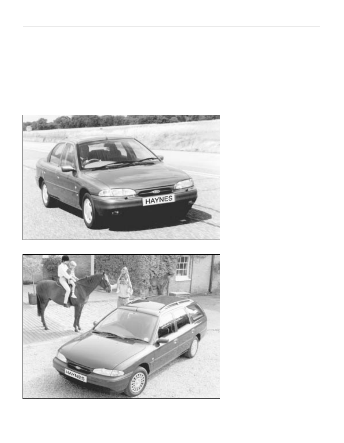
Introduction to the Ford Mondeo
Ford Mondeo 2.0 Ghia Saloon
Ford Mondeo 1.8 GLX Estate
Page 5
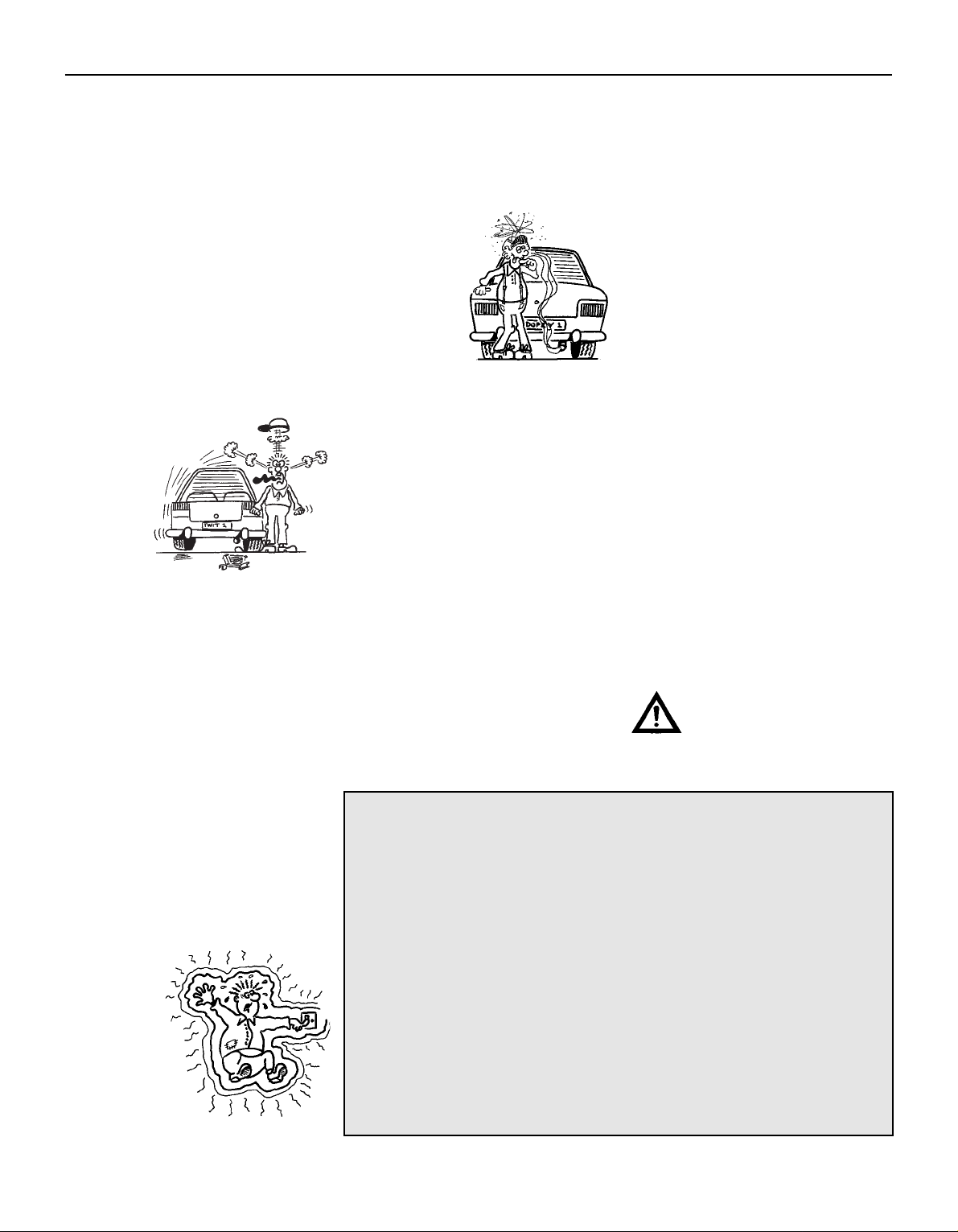
Working on your car can be dangerous.
This page shows just some of the potential
risks and hazards, with the aim of creating a
safety-conscious attitude.
General hazards
Scalding
• Don’t remove the radiator or expansion
tank cap while the engine is hot.
• Engine oil, automatic transmission fluid or
power steering fluid may also be dangerously
hot if the engine has recently been running.
Burning
• Beware of burns from the exhaust system
and from any part of the engine. Brake discs
and drums can also be extremely hot
immediately after use.
Crushing
• When working under or near
a raised vehicle, always
supplement the
jack with axle
stands, or use
drive-on ramps.
Never venture
under a car
which is only
supported by
a jack.
• Take care if loosening or tightening hightorque nuts when the vehicle is on stands.
Initial loosening and final tightening should
be done with the wheels on the ground.
Fire
• Fuel is highly flammable; fuel vapour is
explosive.
• Don’t let fuel spill onto a hot engine.
• Do not smoke or allow naked lights
(including pilot lights) anywhere near a
vehicle being worked on. Also beware of
creating sparks
(electrically or by use of tools).
• Fuel vapour is heavier than air, so don’t
work on the fuel system with the vehicle over
an inspection pit.
• Another cause of fire is an electrical
overload or short-circuit. Take care when
repairing or modifying the vehicle wiring.
• Keep a fire extinguisher handy, of a type
suitable for use on fuel and electrical fires.
Electric shock
• Ignition HT
voltage can be
dangerous,
especially to
people with
heart problems
or a pacemaker.
Don’t work on or
near the ignition
system with the
engine running or the
ignition switched on.
• Mains voltage is also dangerous. Make
sure that any mains-operated equipment is
correctly earthed. Mains power points should
be protected by a residual current device
(RCD) circuit breaker.
Fume or gas intoxication
• Exhaust fumes are
poisonous; they often
contain carbon
monoxide, which is
rapidly fatal if inhaled.
Never run the
engine in a
confined space
such as a garage
with the doors shut.
• Fuel vapour is also
poisonous, as are the vapours from some
cleaning solvents and paint thinners.
Poisonous or irritant substances
• Avoid skin contact with battery acid and
with any fuel, fluid or lubricant, especially
antifreeze, brake hydraulic fluid and Diesel
fuel. Don’t syphon them by mouth. If such a
substance is swallowed or gets into the eyes,
seek medical advice.
• Prolonged contact with used engine oil can
cause skin cancer. Wear gloves or use a
barrier cream if necessary. Change out of oilsoaked clothes and do not keep oily rags in
your pocket.
• Air conditioning refrigerant forms a
poisonous gas if exposed to a naked flame
(including a cigarette). It can also cause skin
burns on contact.
Asbestos
• Asbestos dust can cause cancer if inhaled
or swallowed. Asbestos may be found in
gaskets and in brake and clutch linings.
When dealing with such components it is
safest to assume that they contain asbestos.
Special hazards
Hydrofluoric acid
• This extremely corrosive acid is formed
when certain types of synthetic rubber, found
in some O-rings, oil seals, fuel hoses etc, are
exposed to temperatures above 4000C. The
rubber changes into a charred or sticky
substance containing the acid. Once formed,
the acid remains dangerous for years. If it
gets onto the skin, it may be necessary to
amputate the limb concerned.
• When dealing with a vehicle which has
suffered a fire, or with components salvaged
from such a vehicle, wear protective gloves
and discard them after use.
The battery
• Batteries contain sulphuric acid, which
attacks clothing, eyes and skin. Take care
when topping-up or carrying the battery.
• The hydrogen gas given off by the battery
is highly explosive. Never cause a spark or
allow a naked light nearby. Be careful when
connecting and disconnecting battery
chargers or jump leads.
Air bags
• Air bags can cause injury if they go off
accidentally. Take care when removing the
steering wheel and/or facia. Special storage
instructions may apply.
Diesel injection equipment
• Diesel injection pumps supply fuel at very
high pressure. Take care when working on
the fuel injectors and fuel pipes.
Warning: Never expose the
hands, face or any other part of
the body to injector spray; the
fuel can penetrate the skin with
potentially fatal results.
Remember...
DO
• Do use eye protection when using power
tools, and when working under the vehicle.
• Do wear gloves or use barrier cream to
protect your hands when necessary.
• Do get someone to check periodically
that all is well when working alone on the
vehicle.
• Do keep loose clothing and long hair well
out of the way of moving mechanical parts.
• Do remove rings, wristwatch etc, before
working on the vehicle – especially the
electrical system.
• Do ensure that any lifting or jacking
equipment has a safe working load rating
adequate for the job.
A few tips
DON’T
• Don’t attempt to lift a heavy component
which may be beyond your capability – get
assistance.
• Don’t rush to finish a job, or take
unverified short cuts.
• Don’t use ill-fitting tools which may slip
and cause injury.
• Don’t leave tools or parts lying around
where someone can trip over them. Mop
up oil and fuel spills at once.
• Don’t allow children or pets to play in or
near a vehicle being worked on.
0•5
Safety First!
Page 6

0•6
General Dimensions & Weights
Dimensions
Overall length:
Saloon, Hatchback . . . . . . . . . . . . . . . . . . . . . . . . . . . . . . . . . . . . . 4481 mm
Estate . . . . . . . . . . . . . . . . . . . . . . . . . . . . . . . . . . . . . . . . . . . . . . . 4631 mm
Overall width - including mirrors . . . . . . . . . . . . . . . . . . . . . . . . . . . . . 1925 mm
Overall height - at kerb weight:
Saloon, Hatchback . . . . . . . . . . . . . . . . . . . . . . . . . . . . . . . . . . . . . 1403 to 1435 mm
Estate . . . . . . . . . . . . . . . . . . . . . . . . . . . . . . . . . . . . . . . . . . . . . . . 1416 to 1501 mm
Wheelbase . . . . . . . . . . . . . . . . . . . . . . . . . . . . . . . . . . . . . . . . . . . . . 2704 mm
Front track - all models . . . . . . . . . . . . . . . . . . . . . . . . . . . . . . . . . . . . 1503 mm
Rear track:
Saloon, Hatchback . . . . . . . . . . . . . . . . . . . . . . . . . . . . . . . . . . . . . 1486 to 1487 mm
Estate . . . . . . . . . . . . . . . . . . . . . . . . . . . . . . . . . . . . . . . . . . . . . . . 1504 mm
Turning circle . . . . . . . . . . . . . . . . . . . . . . . . . . . . . . . . . . . . . . . . . . . 10.9 m
Weights
Kerb weight:
1.6 Saloon, Hatchback models . . . . . . . . . . . . . . . . . . . . . . . . . . . . 1215 to 1250 kg
1.6 Estate models . . . . . . . . . . . . . . . . . . . . . . . . . . . . . . . . . . . . . . 1265 to 1275 kg
1.8 Saloon, Hatchback models:
Manual transmission . . . . . . . . . . . . . . . . . . . . . . . . . . . . . . . . . . 1225 to 1260 kg
Automatic transmission . . . . . . . . . . . . . . . . . . . . . . . . . . . . . . . . 1260 to 1280 kg
1.8 Estate models:
Manual transmission . . . . . . . . . . . . . . . . . . . . . . . . . . . . . . . . . . 1275 to 1285 kg
Automatic transmission . . . . . . . . . . . . . . . . . . . . . . . . . . . . . . . . 1305 kg
2.0 Saloon, Hatchback models:
Manual transmission . . . . . . . . . . . . . . . . . . . . . . . . . . . . . . . . . . 1250 to 1310 kg
Automatic transmission . . . . . . . . . . . . . . . . . . . . . . . . . . . . . . . . 1285 to 1340 kg
2.0 Estate models:
Manual transmission . . . . . . . . . . . . . . . . . . . . . . . . . . . . . . . . . . 1295 to 1335 kg
Automatic transmission . . . . . . . . . . . . . . . . . . . . . . . . . . . . . . . . 1330 to 1415 kg
Maximum gross vehicle weight:
Saloon, Hatchback:
1.6 models . . . . . . . . . . . . . . . . . . . . . . . . . . . . . . . . . . . . . . . . . . 1725 kg
1.8 Saloon models, automatic transmission . . . . . . . . . . . . . . . . . 1750 kg
2.0 models, automatic transmission . . . . . . . . . . . . . . . . . . . . . . . 1800 kg
All others . . . . . . . . . . . . . . . . . . . . . . . . . . . . . . . . . . . . . . . . . . . 1775 kg
Estate:
1.6 models, 2.0 models with manual transmission . . . . . . . . . . . . 1900 kg
All others . . . . . . . . . . . . . . . . . . . . . . . . . . . . . . . . . . . . . . . . . . . 1925 kg
Maximum roof rack load:
Estate models with integral roof rack . . . . . . . . . . . . . . . . . . . . . . . . 100 kg
All others . . . . . . . . . . . . . . . . . . . . . . . . . . . . . . . . . . . . . . . . . . . . . 75 kg
Maximum towing weight . . . . . . . . . . . . . . . . . . . . . . . . . . . . . . . . . . . 1500 kg
Trailer nose weight limit . . . . . . . . . . . . . . . . . . . . . . . . . . . . . . . . . . . . 75 kg
Page 7
0•7
This is a guide to getting your vehicle through the MOT test.
Obviously it will not be possible to examine the vehicle to the same
standard as the professional MOT tester. However, working through
the following checks will enable you to identify any problem areas
before submitting the vehicle for the test.
Where a testable component is in borderline condition, the tester
has discretion in deciding whether to pass or fail it. The basis of such
discretion is whether the tester would be happy for a close relative or
friend to use the vehicle with the component in that condition. If the
vehicle presented is clean and evidently well cared for, the tester may
be more inclined to pass a borderline component than if the vehicle is
scruffy and apparently neglected.
It has only been possible to summarise the test requirements here,
based on the regulations in force at the time of printing. Test standards
are becoming increasingly stringent, although there are some
exemptions for older vehicles. For full details obtain a copy of the Haynes
publication Pass the MOT! (available from stockists of Haynes manuals).
An assistant will be needed to help carry out some of these checks.
The checks have been sub-divided into four categories, as follows:
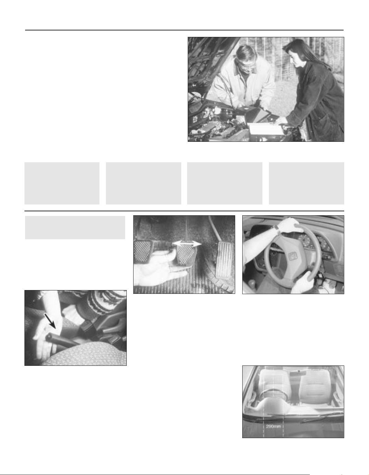
Handbrake
M Test the operation of the handbrake.
Excessive travel (too many clicks) indicates
incorrect brake or cable adjustment.
M Check that the handbrake cannot be
released by tapping the lever sideways. Check
the security of the lever mountings.
Footbrake
M Depress the brake pedal and check that it
does not creep down to the floor, indicating a
master cylinder fault. Release the pedal, wait
a few seconds, then depress it again. If the
pedal travels nearly to the floor before firm
resistance is felt, brake adjustment or repair is
necessary. If the pedal feels spongy, there is
air in the hydraulic system which must be
removed by bleeding.
M Check that the brake pedal is secure and in
good condition. Check also for signs of fluid
leaks on the pedal, floor or carpets, which
would indicate failed seals in the brake master
cylinder .
M Check the servo unit (when applicable) by
operating the brake pedal several times, then
keeping the pedal depressed and starting the
engine. As the engine starts, the pedal will
move down slightly. If not, the vacuum hose or
the servo itself may be faulty.
Steering wheel and column
M Examine the steering wheel for fractures or
looseness of the hub, spokes or rim.
M Move the steering wheel from side to side
and then up and down. Check that the
steering wheel is not loose on the column,
indicating wear or a loose retaining nut.
Continue moving the steering wheel as before,
but also turn it slightly from left to right.
M Check that the steering wheel is not loose
on the column, and that there is no abnormal
movement of the steering wheel, indicating
wear in the column support bearings or
couplings.
Windscreen and mirrors
M The windscreen must be free of cracks or
other significant damage within the driver’s
field of view. (Small stone chips are
acceptable.) Rear view mirrors must be
secure, intact, and capable of being adjusted.
1Checks carried out
FROM THE DRIVER’S SEAT
MOT Test Checks
1Checks carried out
FROM THE DRIVER’S
SEAT
2Checks carried out
WITH THE VEHICLE
ON THE GROUND
3Checks carried out
WITH THE VEHICLE
RAISED AND THE
WHEELS FREE TO
TURN
4Checks carried out on
YOUR VEHICLE’S
EXHAUST EMISSION
SYSTEM
Page 8
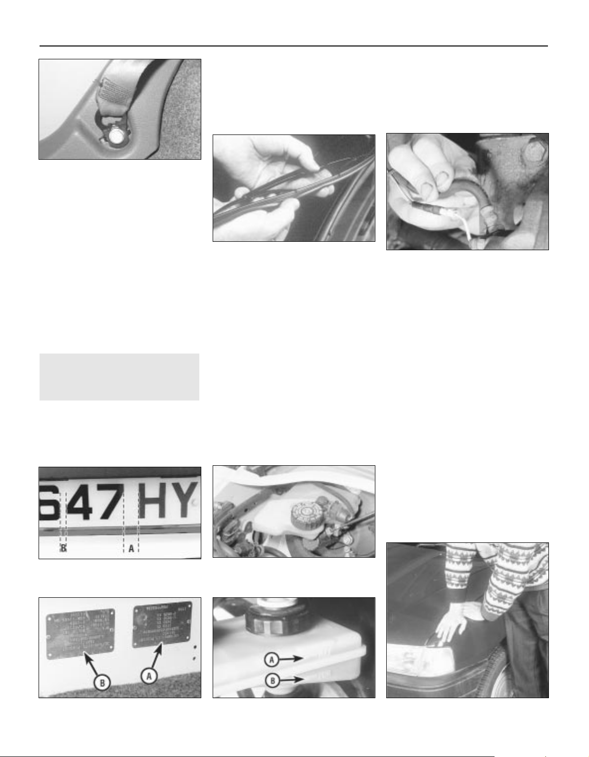
Seat belts and seats
Note: The following checks are applicable to
all seat belts, front and rear.
M Examine the webbing of all the belts
(including rear belts if fitted) for cuts, serious
fraying or deterioration. Fasten and unfasten
each belt to check the buckles. If applicable,
check the retracting mechanism. Check the
security of all seat belt mountings accessible
from inside the vehicle.
M The front seats themselves must be
securely attached and the backrests must
lock in the upright position.
Doors
M Both front doors must be able to be opened
and closed from outside and inside, and must
latch securely when closed.
Vehicle identification
M Number plates must be in good condition,
secure and legible, with letters and numbers
correctly spaced – spacing at (A) should be
twice that at (B).
M The VIN plate (A) and homologation plate
(B) must be legible.
Electrical equipment
M Switch on the ignition and check the
operation of the horn.
M Check the windscreen washers and wipers,
examining the wiper blades; renew damaged
or perished blades. Also check the operation
of the stop-lights.
M Check the operation of the sidelights and
number plate lights. The lenses and reflectors
must be secure, clean and undamaged.
M Check the operation and alignment of the
headlights. The headlight reflectors must not
be tarnished and the lenses must be
undamaged.
M Switch on the ignition and check the
operation of the direction indicators (including
the instrument panel tell-tale) and the hazard
warning lights. Operation of the sidelights and
stop-lights must not affect the indicators - if it
does, the cause is usually a bad earth at the
rear light cluster.
M Check the operation of the rear foglight(s),
including the warning light on the instrument
panel or in the switch.
Footbrake
M Examine the master cylinder, brake pipes
and servo unit for leaks, loose mountings,
corrosion or other damage.
M The fluid reservoir must be secure and the
fluid level must be between the upper (A) and
lower (B) markings.
M Inspect both front brake flexible hoses for
cracks or deterioration of the rubber. Turn the
steering from lock to lock, and ensure that the
hoses do not contact the wheel, tyre, or any
part of the steering or suspension mechanism.
With the brake pedal firmly depressed, check
the hoses for bulges or leaks under pressure.
Steering and suspension
M Have your assistant turn the steering wheel
from side to side slightly , up to the point where
the steering gear just begins to transmit this
movement to the roadwheels. Check for
excessive free play between the steering
wheel and the steering gear , indicating wear or
insecurity of the steering column joints, the
column-to-steering gear coupling, or the
steering gear itself.
M Have your assistant turn the steering wheel
more vigorously in each direction, so that the
roadwheels just begin to turn. As this is done,
examine all the steering joints, linkages,
fittings and attachments. Renew any
component that shows signs of wear or
damage. On vehicles with power steering,
check the security and condition of the
steering pump, drivebelt and hoses.
M Check that the vehicle is standing level,
and at approximately the correct ride height.
Shock absorbers
M Depress each corner of the vehicle in tur n,
then release it. The vehicle should rise and
then settle in its normal position. If the vehicle
continues to rise and fall, the shock absorber
is defective. A shock absorber which has
seized will also cause the vehicle to fail.
2Checks carried out
WITH THE VEHICLE ON THE
GROUND
0•8
MOT Test Checks
Page 9
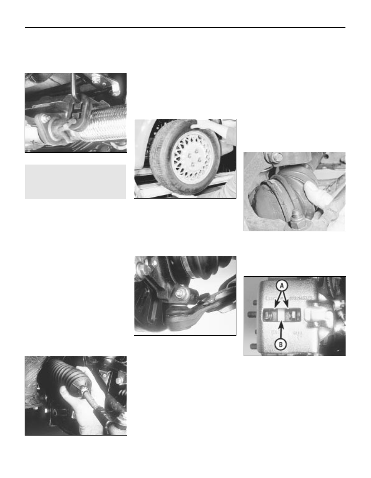
Exhaust system
M Start the engine. With your assistant
holding a rag over the tailpipe, check the
entire system for leaks. Repair or renew
leaking sections.
Jack up the front and rear of the vehicle,
and securely support it on axle stands.
Position the stands clear of the suspension
assemblies. Ensure that the wheels are
clear of the ground and that the steering
can be turned from lock to lock.
Steering mechanism
M Have your assistant tur n the steering from
lock to lock. Check that the steering turns
smoothly, and that no part of the steering
mechanism, including a wheel or tyre, fouls
any brake hose or pipe or any part of the body
structure.
M Examine the steering rack rubber gaiters
for damage or insecurity of the retaining clips.
If power steering is fitted, check for signs of
damage or leakage of the fluid hoses, pipes or
connections. Also check for excessive
stiffness or binding of the steering, a missing
split pin or locking device, or severe corrosion
of the body structure within 30 cm of any
steering component attachment point.
Front and rear suspension and
wheel bearings
M Starting at the front right-hand side, grasp
the roadwheel at the 3 o’clock and 9 o’clock
positions and shake it vigorously. Check for
free play or insecurity at the wheel bearings,
suspension balljoints, or suspension mountings, pivots and attachments.
M Now grasp the wheel at the 12 o’clock and
6 o’clock positions and repeat the previous
inspection. Spin the wheel, and check for
roughness or tightness of the front wheel
bearing.
M If excess free play is suspected at a
component pivot point, this can be confirmed
by using a large screwdriver or similar tool and
levering between the mounting and the
component attachment. This will confirm
whether the wear is in the pivot bush, its
retaining bolt, or in the mounting itself (the bolt
holes can often become elongated).
M Carry out all the above checks at the other
front wheel, and then at both rear wheels.
Springs and shock absorbers
M Examine the suspension struts (when
applicable) for serious fluid leakage, corrosion,
or damage to the casing. Also check the
security of the mounting points.
M If coil springs are fitted, check that the
spring ends locate in their seats, and that the
spring is not corroded, cracked or broken.
M If leaf springs are fitted, check that all
leaves are intact, that the axle is securely
attached to each spring, and that there is no
deterioration of the spring eye mountings,
bushes, and shackles.
M The same general checks apply to vehicles
fitted with other suspension types, such as
torsion bars, hydraulic displacer units, etc.
Ensure that all mountings and attachments are
secure, that there are no signs of excessive
wear, corrosion or damage, and (on hydraulic
types) that there are no fluid leaks or damaged
pipes.
M Inspect the shock absorbers for signs of
serious fluid leakage. Check for wear of the
mounting bushes or attachments, or damage
to the body of the unit.
Driveshafts
(fwd vehicles only)
M Rotate each front wheel in turn and inspect
the constant velocity joint gaiters for splits or
damage. Also check that each driveshaft is
straight and undamaged.
Braking system
M If possible without dismantling, check
brake pad wear and disc condition. Ensure
that the friction lining material has not worn
excessively, (A) and that the discs are not
fractured, pitted, scored or badly worn (B).
M Examine all the rigid brake pipes
underneath the vehicle, and the flexible
hose(s) at the rear. Look for corrosion, chafing
or insecurity of the pipes, and for signs of
bulging under pressure, chafing, splits or
deterioration of the flexible hoses.
M Look for signs of fluid leaks at the brake
calipers or on the brake backplates. Repair or
renew leaking components.
M Slowly spin each wheel, while your
assistant depresses and releases the
footbrake. Ensure that each brake is operating
and does not bind when the pedal is released.
3Checks carried out
WITH THE VEHICLE RAISED
AND THE WHEELS FREE TO
TURN
0•9
MOT Test Checks
Page 10
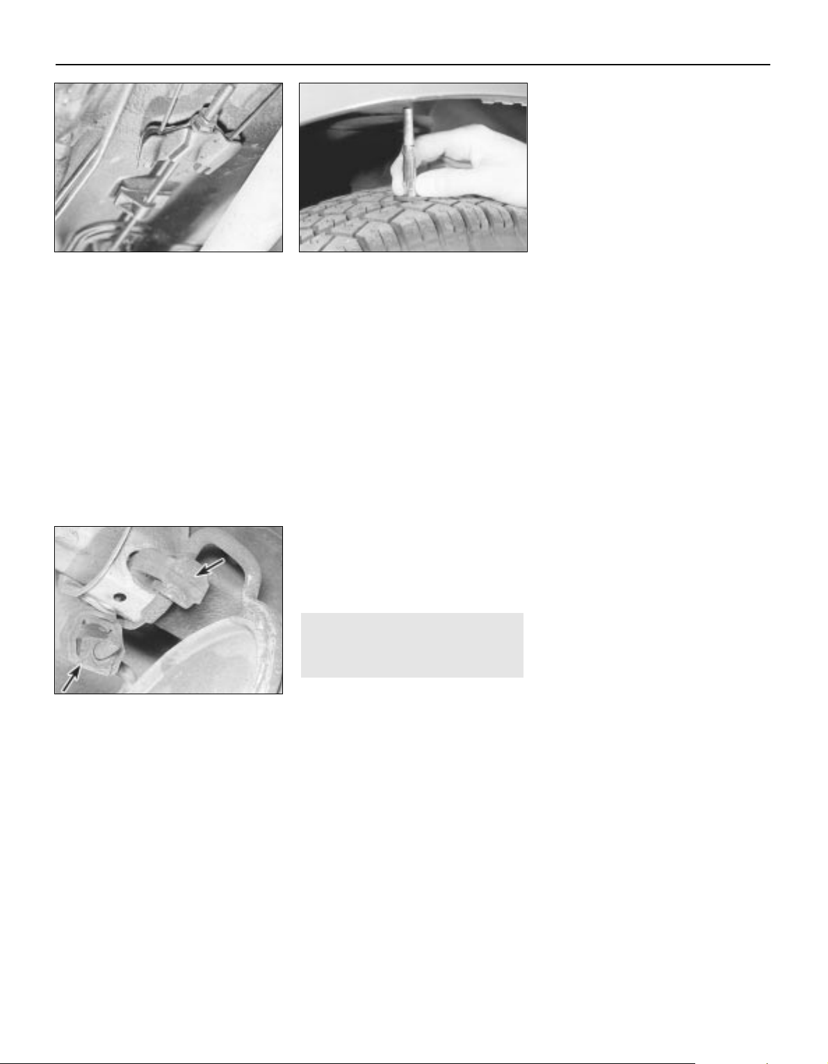
0•10
M Examine the handbrake mechanism,
checking for frayed or broken cables,
excessive corrosion, or wear or insecurity of
the linkage. Check that the mechanism works
on each relevant wheel, and releases fully,
without binding.
M It is not possible to test brake efficiency
without special equipment, but a road test
can be carried out later to check that the
vehicle pulls up in a straight line.
Fuel and exhaust systems
M Inspect the fuel tank (including the filler
cap), fuel pipes, hoses and unions. All
components must be secure and free from
leaks.
M Examine the exhaust system over its entire
length, checking for any damaged, broken or
missing mountings, security of the retaining
clamps and rust or corrosion.
Wheels and tyres
M Examine the sidewalls and tread area of
each tyre in turn. Check for cuts, tears, lumps,
bulges, separation of the tread, and exposure
of the ply or cord due to wear or damage.
Check that the tyre bead is correctly seated
on the wheel rim, that the valve is sound and
properly seated, and that the wheel is not
distorted or damaged.
M Check that the tyres are of the correct size
for the vehicle, that they are of the same size
and type on each axle, and that the pressures
are correct.
M Check the tyre tread depth. The legal
minimum at the time of writing is 1.6 mm over
at least three-quarters of the tread width.
Abnormal tread wear may indicate incorrect
front wheel alignment.
Body corrosion
M Check the condition of the entire vehicle
structure for signs of corrosion in loadbearing areas. (These include chassis box
sections, side sills, cross-members, pillars,
and all suspension, steering, braking system
and seat belt mountings and anchorages.)
Any corrosion which has seriously reduced
the thickness of a load-bearing area is likely to
cause the vehicle to fail. In this case
professional repairs are likely to be needed.
M Damage or corrosion which causes sharp
or otherwise dangerous edges to be exposed
will also cause the vehicle to fail.
Petrol models
M Have the engine at normal operating
temperature, and make sure that it is in good
tune (ignition system in good order, air filter
element clean, etc).
M Before any measurements are carried out,
raise the engine speed to around 2500 rpm,
and hold it at this speed for 20 seconds. Allow
the engine speed to return to idle, and watch
for smoke emissions from the exhaust
tailpipe. If the idle speed is obviously much
too high, or if dense blue or clearly-visible
black smoke comes from the tailpipe for more
than 5 seconds, the vehicle will fail. As a rule
of thumb, blue smoke signifies oil being burnt
(engine wear) while black smoke signifies
unburnt fuel (dirty air cleaner element, or other
carburettor or fuel system fault).
M An exhaust gas analyser capable of
measuring carbon monoxide (CO) and
hydrocarbons (HC) is now needed. If such an
instrument cannot be hired or borrowed, a
local garage may agree to perform the check
for a small fee.
CO emissions (mixture)
M At the time or writing, the maximum CO
level at idle is 3.5% for vehicles first used after
August 1986 and 4.5% for older vehicles.
From January 1996 a much tighter limit
(around 0.5%) applies to catalyst-equipped
vehicles first used from August 1992. If the
CO level cannot be reduced far enough to
pass the test (and the fuel and ignition
systems are otherwise in good condition) then
the carburettor is badly worn, or there is some
problem in the fuel injection system or
catalytic converter (as applicable).
HC emissions
M With the CO emissions within limits, HC
emissions must be no more than 1200 ppm
(parts per million). If the vehicle fails this test
at idle, it can be re-tested at around 2000
rpm; if the HC level is then 1200 ppm or less,
this counts as a pass.
M Excessive HC emissions can be caused by
oil being burnt, but they are more likely to be
due to unburnt fuel.
Diesel models
M The only emission test applicable to Diesel
engines is the measuring of exhaust smoke
density. The test involves accelerating the
engine several times to its maximum
unloaded speed.
Note: It is of the utmost importance that the
engine timing belt is in good condition before
the test is carried out.
M
Excessive smoke can be caused by a dirty
air cleaner element. Otherwise, professional
advice may be needed to find the cause.
4Checks carried out on
YOUR VEHICLE’S EXHAUST
EMISSION SYSTEM
MOT Test Checks
Page 11
0•11
Roadside Repairs
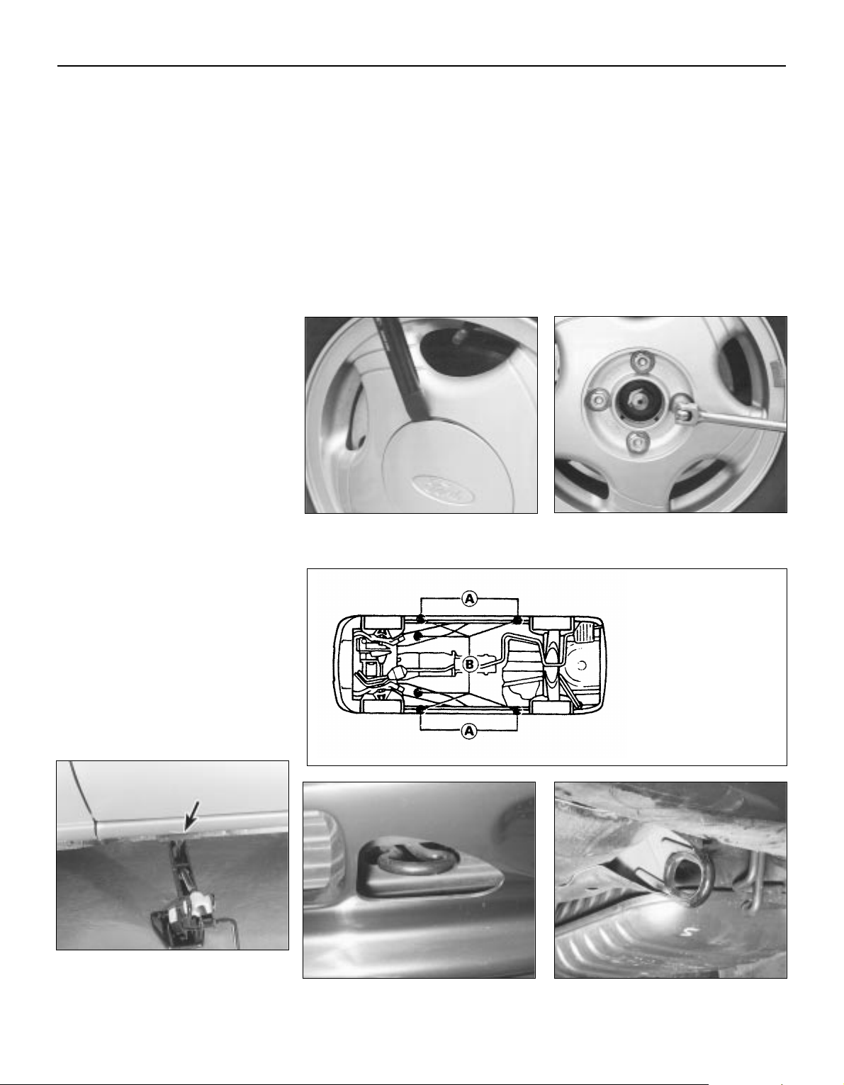
To change a wheel, remove the spare
wheel and jack, apply the handbrake, and
chock the wheel diagonally opposite the
one to be changed. On manual transmission
models, select first or reverse gear; on
automatic transmission models, place the
selector lever in “P”. Make sure that the
vehicle is located on firm level ground. Use
the flat end of the wheelbrace carefully to
remove the trim covering the wheel nuts,
then slightly loosen the wheel nuts with the
brace (see illustrations). Locate the jack
head in the jacking point nearest to the
wheel to be changed, ensuring that the
channel in the jack head fits over the body
flange (see illustrations) and turn its
handle to raise the jack. When the wheel is
clear of the ground, remove the nuts and lift
off the wheel. Fit the spare wheel, and
moderately tighten the nuts. Lower the
vehicle, then tighten the nuts fully and refit
the trim. With the spare wheel in position,
remove the chock, and stow the jack and
tools.
When jacking up the vehicle to carry out
repair or maintenance tasks, position the jack
as follows.
If the front of the vehicle is to be raised,
either place the jack head under the sump,
with a block of wood to prevent damage, or
place a jacking beam across the two front
points “B” shown in the accompanying
illustration, and lift the vehicle evenly.
To raise the rear of the vehicle, place a
jacking beam across the two rear points “B”
shown in the accompanying illustration, and
lift the vehicle evenly.
To raise the side of the vehicle, place the
jack head under the appropriate point
indicated in the accompanying illustration - if
a trolley jack or similar is used on the points
“A” provided for the vehicle’s jack, make up a
wooden spacer with a groove cut in it to
accept the underbody flange, so that there is
no risk of the jack slipping or buckling the
flange. Never work under, around or near a
raised vehicle unless it is adequately
supported in at least two places with axle
stands or suitable sturdy blocks.
The vehicle may be towed, for breakdown
recovery purposes only , using the towing eyes
positioned at the front and rear of the vehicle
(see illustrations). These eyes are intended
for towing loads only, and must not be used
for lifting the vehicle, either directly or
indirectly.
If the vehicle is equipped with automatic
transmission, the following precautions must
be observed if the vehicle is to be towed,
particularly if any kind of transmission fault is
suspected. Preferably , a fr ont-end-suspended
tow should be used (ie with the front wheels
off the ground). If this is not possible, place
the selector lever in “N” and tow the vehicle forwards only, never backwards - for a
distance of no more than 30 miles (50 km),
and at speeds no greater than 30 mph
(50 km/h).
Jacking, towing and wheel changing
Front towing eye Rear towing eye
Use flat end of wheelbrace to remove trim
covering roadwheel nuts
Slacken roadwheel nuts in diagonal
sequence
With jack base on firm ground, locate jack
head in jacking point - indentations
(arrowed) in sill identify jacking points
Jacking and supporting
points
A Jacking points (for
vehicle jack in roadside
use) - support points (for
axle stands in
servicing/overhaul work)
B Jacking points (for
trolley jack or workshop
hoist in
servicing/overhaul work)
- additional support
points
Page 12
0•12
When jump-starting a car using a
booster battery, observe the following
precautions:
A) Before connecting the booster
battery, make sure that the ignition is
switched off.
B) Ensure that all electrical equipment
(lights, heater, wipers, etc) is
switched off.
C) Make sure that the booster battery is
the same voltage as the discharged
one in the vehicle.
D) If the battery is being jump-started
from the battery in another vehicle,
the two vehcles MUST NOT TOUCH
each other.
E) Make sure that the transmission is in
neutral (or PARK, in the case of
automatic transmission).
Jump starting will get you out
of trouble, but you must correct
whatever made the battery go
flat in the first place. There are
three possibilities:
1
The battery has been drained by
repeated attempts to start, or by
leaving the lights on.
2
The charging system is not working
properly (alternator drivebelt slack
or broken, alternator wiring fault or
alternator itself faulty).
3
The battery itself is at fault
(electrolyte low, or battery worn out).
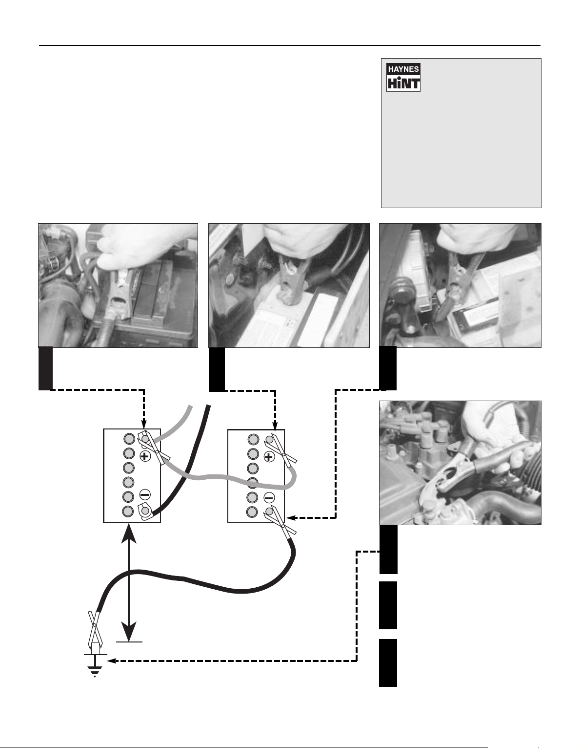
Connect one end of the red jump lead to
the positive (+) terminal of the flat
battery
Connect the other end of the red lead to
the positive (+) terminal of the booster
battery.
Connect one end of the black jump lead
to the negative (-) terminal of the
booster battery
Connect the other end of the black
jump lead to a bolt or bracket on the
engine block, well away from the
battery, on the vehicle to be started.
1
2
3
4
Make sure that the jump leads will not
come into contact with the fan, drive-
belts or other moving parts of the
engine.
5
Start the engine using the booster
battery, then with the engine running at
idle speed, disconnect the jump leads in
the reverse order of connection.
6
Roadside Repairs
Booster battery (jump) starting
Page 13
0•13
Roadside Repairs
Puddles on the garage floor or drive, or
obvious wetness under the bonnet or
underneath the car, suggest a leak that needs
investigating. It can sometimes be difficult to
decide where the leak is coming from,
especially if the engine bay is very dirty
already. Leaking oil or fluid can also be blown
rearwards by the passage of air under the car,
giving a false impression of where the
problem lies.
Warning: Most automotive oils
and fluids are poisonous. Wash
them off skin, and change out of
contaminated clothing, without
delay.
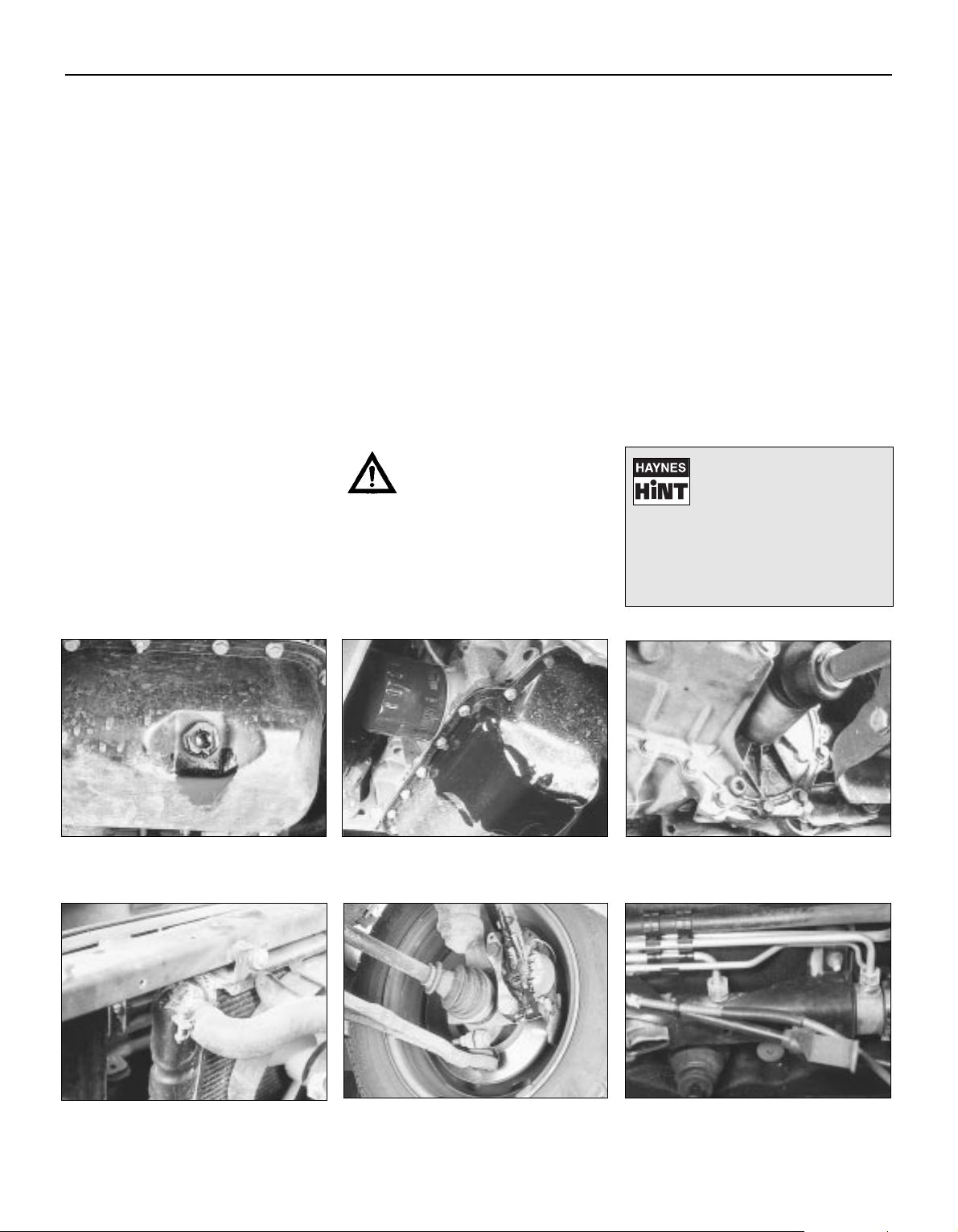
Identifying leaks
The smell of a fluid leaking
from the car may provide a
clue to what’s leaking. Some
fluids are distictively coloured.
It may help to clean the car carefully
and to park it over some clean paper
overnight as an aid to locating the
source of the leak.
Remember that some leaks may only
occur while the engine is running.
Sump oil
Gearbox oil
Brake fluid Power steering fluid
Oil from filter
Antifreeze
Engine oil may leak from the drain plug... ...or from the base of the oil filter.
Leaking antifreeze often leaves a crystalline
deposit like this.
Gearbox oil can leak from the seals at the
inboard ends of the driveshafts.
A leak occurring at a wheel is almost
certainly brake fluid.
Power steering fluid may leak from the pipe
connectors on the steering rack.
Page 14

0•14
Conversion Factors
Length (distance)
Inches (in) x 25.4 = Millimetres (mm) x 0.0394 = Inches (in)
Feet (ft) x 0.305 = Metres (m) x 3.281 = Feet (ft)
Miles x 1.609 = Kilometres (km) x 0.621 = Miles
Volume (capacity)
Cubic inches (cu in; in3) x 16.387 = Cubic centimetres (cc; cm3) x 0.061 = Cubic inches (cu in; in3)
Imperial pints (Imp pt) x 0.568 = Litres (l) x 1.76 = Imperial pints (Imp pt)
Imperial quarts (Imp qt) x 1.137 = Litres (l) x 0.88 = Imperial quarts (Imp qt)
Imperial quarts (Imp qt) x 1.201 = US quarts (US qt) x 0.833 = Imperial quarts (Imp qt)
US quarts (US qt) x 0.946 = Litres (l) x 1.057 = US quarts (US qt)
Imperial gallons (Imp gal) x 4.546 = Litres (l) x 0.22 = Imperial gallons (Imp gal)
Imperial gallons (Imp gal) x 1.201 = US gallons (US gal) x 0.833 = Imperial gallons (Imp gal)
US gallons (US gal) x 3.785 = Litres (l) x 0.264 = US gallons (US gal)
Mass (weight)
Ounces (oz) x 28.35 = Grams (g) x 0.035 = Ounces (oz)
Pounds (lb) x 0.454 = Kilograms (kg) x 2.205 = Pounds (lb)
Force
Ounces-force (ozf; oz) x 0.278 = Newtons (N) x 3.6 = Ounces-force (ozf; oz)
Pounds-force (lbf; lb) x 4.448 = Newtons (N) x 0.225 = Pounds-force (lbf; lb)
Newtons (N) x 0.1 = Kilograms-force (kgf; kg) x 9.81 = Newtons (N)
Pressure
Pounds-force per square inch x 0.070 = Kilograms-force per square x 14.223 = Pounds-force per square inch
(psi; lbf/in2; lb/in2) centimetre (kgf/cm2; kg/cm2) (psi; lbf/in2; lb/in2)
Pounds-force per square inch x 0.068 = Atmospheres (atm) x 14.696 = Pounds-force per square inch
(psi; lbf/in2; lb/in2) (psi; lbf/in2; lb/in2)
Pounds-force per square inch x 0.069 = Bars x 14.5 = Pounds-force per square inch
(psi; lbf/in2; lb/in2) (psi; lbf/in2; lb/in2)
Pounds-force per square inch x 6.895 = Kilopascals (kPa) x 0.145 = Pounds-force per square inch
(psi; lbf/in2; lb/in2) (psi; lbf/in2; lb/in2)
Kilopascals (kPa) x 0.01 = Kilograms-force per square x 98.1 = Kilopascals (kPa)
centimetre (kgf/cm2; kg/cm2)
Millibar (mbar) x 100 = Pascals (Pa) x 0.01 = Millibar (mbar)
Millibar (mbar) x 0.0145 = Pounds-force per square inch x 68.947 = Millibar (mbar)
(psi; lbf/in2; lb/in2)
Millibar (mbar) x 0.75 = Millimetres of mercury (mmHg) x 1.333 = Millibar (mbar)
Millibar (mbar) x 0.401 = Inches of water (inH2O) x 2.491 = Millibar (mbar)
Millimetres of mercury (mmHg) x 0.535 = Inches of water (inH2O) x 1.868 = Millimetres of mercury (mmHg)
Inches of water (inH
2
O) x 0.036 = Pounds-force per square inch x 27.68 = Inches of water (inH2O)
(psi; lbf/in2; lb/in2)
Torque (moment of force)
Pounds-force inches x 1.152 = Kilograms-force centimetre x 0.868 = Pounds-force inches
(lbf in; lb in) (kgf cm; kg cm) (lbf in; lb in)
Pounds-force inches x 0.113 = Newton metres (Nm) x 8.85 = Pounds-force inches
(lbf in; lb in) (lbf in; lb in)
Pounds-force inches x 0.083 = Pounds-force feet (lbf ft; lb ft) x 12 = Pounds-force inches
(lbf in; lb in) (lbf in; lb in)
Pounds-force feet (lbf ft; lb ft) x 0.138 = Kilograms-force metres x 7.233 = Pounds-force feet (lbf ft; lb ft)
(kgf m; kg m)
Pounds-force feet (lbf ft; lb ft) x 1.356 = Newton metres (Nm) x 0.738 = Pounds-force feet (lbf ft; lb ft)
Newton metres (Nm) x 0.102 = Kilograms-force metres x 9.804 = Newton metres (Nm)
(kgf m; kg m)
Power
Horsepower (hp) x 745.7 = Watts (W) x 0.0013 = Horsepower (hp)
Velocity (speed)
Miles per hour (miles/hr; mph) x 1.609 = Kilometres per hour (km/hr; kph) x 0.621 = Miles per hour (miles/hr; mph)
Fuel consumption*
Miles per gallon (mpg) x 0.354 = Kilometres per litre (km/l) x 2.825 = Miles per gallon (mpg)
Temperature
Degrees Fahrenheit = (°C x 1.8) + 32 Degrees Celsius (Degrees Centigrade; °C) = (°F - 32) x 0.56
* It is common practice to convert from miles per gallon (mpg) to litres/100 kilometres (l/100km), where mpg x l/100 km = 282
Page 15

Chapter 1 Routine maintenance and servicing
Air conditioning system check . . . . . . . . . . . . . . . . . . . . . . . . . . . . . 14
Air filter element renewal . . . . . . . . . . . . . . . . . . . . . . . . . . . . . . . . . . 29
Automatic transmission fluid level check . . . . . . . . . . . . . . . . . . . . . 7
Automatic transmission linkage lubrication . . . . . . . . . . . . . . . . . . . 18
Auxiliary drivebelt check and renewal . . . . . . . . . . . . . . . . . . . . . . . . 11
Battery check, maintenance and charging . . . . . . . . . . . . . . . . . . . . 9
Brake check . . . . . . . . . . . . . . . . . . . . . . . . . . . . . . . . . . . . . . . . . . . 23
Brake fluid renewal . . . . . . . . . . . . . . . . . . . . . . . . . . . . . . . . . . . . . . 34
Clutch pedal adjustment . . . . . . . . . . . . . . . . . . . . . . . . . . . . . . . . . . 17
Coolant renewal . . . . . . . . . . . . . . . . . . . . . . . . . . . . . . . . . . . . . . 2, 28
Door and bonnet check and lubrication . . . . . . . . . . . . . . . . . . . . . . 24
Driveshaft rubber gaiter and CV joint check . . . . . . . . . . . . . . . . . . . 20
Electrical system check . . . . . . . . . . . . . . . . . . . . . . . . . . . . . . . . . . . 8
Engine compartment wiring check . . . . . . . . . . . . . . . . . . . . . . . . . . 13
Engine oil and filter change . . . . . . . . . . . . . . . . . . . . . . . . . . . . . . . . 15
Exhaust system check . . . . . . . . . . . . . . . . . . . . . . . . . . . . . . . . . . . 21
Fluid level checks . . . . . . . . . . . . . . . . . . . . . . . . . . . . . . . . . . . . . . . 3
Fuel filter renewal . . . . . . . . . . . . . . . . . . . . . . . . . . . . . . . . . . . . . . . 33
Idle speed and mixture check and adjustment . . . . . . See Chapter 4
Ignition timing check . . . . . . . . . . . . . . . . . . . . . . . . . . See Chapter 5
Introduction . . . . . . . . . . . . . . . . . . . . . . . . . . . . . . . . . . . . . . . . . . . . 1
Manual transmission oil level check . . . . . . . . . . . . . . . . . . . . . . . . . 16
Positive Crankcase Ventilation (PCV) system check
and filter cleaning . . . . . . . . . . . . . . . . . . . . . . . . . . . . . . . . . . . . . 30
Power steering fluid level check . . . . . . . . . . . . . . . . . . . . . . . . . . . . 5
Road test . . . . . . . . . . . . . . . . . . . . . . . . . . . . . . . . . . . . . . . . . . . . . . 26
Roadwheel nut tightness check . . . . . . . . . . . . . . . . . . . . . . . . . . . . 25
Seat belt check . . . . . . . . . . . . . . . . . . . . . . . . . . . . . . . . . . . . . . . . . 10
Spark plug renewal . . . . . . . . . . . . . . . . . . . . . . . . . . . . . . . . . . . . . . 31
Specifications . . . . . . . . . . . . . . . . . . . . . . . . . . . . See end of Chapter
Steering, suspension and roadwheel check . . . . . . . . . . . . . . . . . . . 19
Timing belt renewal . . . . . . . . . . . . . . . . . . . . . . . . . . . . . . . . . . . . . . 32
Tyre and tyre pressure checks . . . . . . . . . . . . . . . . . . . . . . . . . . . . . 4
Underbody and fuel/brake line check . . . . . . . . . . . . . . . . . . . . . . . . 22
Underbonnet check for fluid leaks and hose condition . . . . . . . . . . 12
Ventilation system pollen filter renewal . . . . . . . . . . . . . . . . . . . . . . . 27
Windscreen/tailgate washer system and wiper blade check . . . . . . 6
1•1
Easy, suitable for
novice with little
experience
Fairly easy, suitable
for beginner with
some experience
Fairly difficult, suitable
for competent DIY
mechanic
Difficult, suitable for
experienced DIY
mechanic
Very difficult,
suitable for expert DIY
or professional
Degrees of difficulty
Contents
1
Page 16
1•2
Lubricants, Fluids & Capacities
Lubricants and fluids
Component or system Lubricant type/specification
Engine Multigrade engine oil to specification API SG/CD or better, viscosity range 5W/50 to 10W/30
Manual transmission Gear oil to Ford specification ESD-M2C-186-A
Automatic transmission Transmission fluid to Ford specification ESP-M2C-166-H
Power steering Transmission fluid to Ford specification ESP-M2C-166-H
Cooling system Soft water, and antifreeze (ethylene glycol-based, suitable for use in mixed-metal cooling systems) to
Ford specification ESD-M97B-49-A
Braking system Hydraulic fluid to Ford specification ESD-M6C-57-A, Super DOT 4 or equivalent
Driveshaft joints Long-life grease to Ford specification SQM-1C 9004-A
Capacities
Engine oil:
At oil and filter change . . . . . . . . . . . . . . . . . . . . . . . 4.25 litres
Dry - at engine overhaul . . . . . . . . . . . . . . . . . . . . . . 4.50 litres
Difference between dipstick minimum and
maximum level notches . . . . . . . . . . . . . . . . . . . . . . 0.5 to 1.0 litre
Fuel tank . . . . . . . . . . . . . . . . . . . . . . . . . . . . . . . . . . . 61.5 litres
Cooling system:
Manual transmission models . . . . . . . . . . . . . . . . . . 6.6 litres
Automatic transmission models . . . . . . . . . . . . . . . 7.1 litres
Manual transmission . . . . . . . . . . . . . . . . . . . . . . . . . . 2.6 litres
Automatic transmission:
Total, including fluid cooler . . . . . . . . . . . . . . . . . . . 7.2 litres
Drain and refill . . . . . . . . . . . . . . . . . . . . . . . . . . . . . 3.6 litres
Page 17

Ford Mondeo maintenance schedule
1•3
1
Maintenance schedule
The manufacturer’s recommended maintenance schedule for these
vehicles is as described below - note that the schedule starts from the
vehicle’s date of registration. These are the minimum maintenance
intervals recommended by the factory for Mondeos driven daily, but
subjected only to “normal” use. If you wish to keep your vehicle in
peak condition at all times, you may wish to perform some of these
procedures even more often. Because frequent maintenance
enhances the efficiency, performance and resale value of your vehicle,
we encourage you to do so. If your usage is not “normal”, shorter
intervals are also recommended - the most important examples of
these are noted in the schedule. These shorter intervals apply
particularly if you drive in dusty areas, tow a caravan or trailer, sit with
the engine idling or drive at low speeds for extended periods (ie, in
heavy traffic), or drive for short distances (less than four miles) in
below-freezing temperatures.
When your vehicle is new, it should be serviced by a Ford dealer
service department to protect the factory warranty. In many cases, the
initial maintenance check is done at no cost to the owner. Note that
this first free service (carried out by the selling dealer 1500 miles or 3
months after delivery), although an important check for a new vehicle,
is not part of the regular maintenance schedule, and is therefore not
mentioned here.
Weekly checks
mm Check the engine oil level, and top-up if necessary
(Section 3)
mm Check the brake fluid level, and top-up if necessary
(Section 3). If repeated topping-up is required, check the
system for leaks or damage at the earliest possible
opportunity (Sections 12 and 22)
mm Check the windscreen/tailgate washer fluid level, and top-
up if necessary (Section 3)
mm Check the tyre pressures, including the spare (Section 4)
mm Visually check the tyres for excessive tread wear, or
damage (Section 4)
mm Check the operation of all (exterior and interior) lights and
the horn, wipers and windscreen/tailgate washer system
(Sections 6 and 8). Renew any blown bulbs (Chapter 12),
and clean the lenses of all exterior lights
Monthly checks
mm Check the coolant level, and top-up if necessary (Sec-
tion 3)
mm Check the battery electrolyte level, where applicable
(Section 3)
mm Check the power steering fluid level, and top-up if
necessary (Section 5)
mm Visually check all reservoirs, hoses and pipes for leakage
(Section 12)
mm Check the operation of the air conditioning system
(Section 14)
mm Check the operation of the handbrake (Section 23)
mm Check the aim of the windscreen/tailgate/headlight
washer jets, correcting them if required (Section 6)
mm Check the condition of the wiper blades, renewing them if
worn or no longer effective - note that the manufacturer
recommends renewing the blades as a safety precaution,
irrespective of their apparent condition, at least once a
year (Section 6)
Every 10 000 miles or 12 months,
whichever occurs first
Note: If the vehicle is used regularly for very short (less than
10 miles), stop/go journeys, the oil and filter should be renewed
between services (ie, every 5000 miles/6 months).
mm Check the electrical system (Section 8)
mm Check the battery (Section 9)
mm Check the seat belts (Section 10)
mm Check the auxiliary drivebelt (Section 11)
mm Check for fluid leaks and hose condition (Section 12)
mm Check the condition of all wiring (Section 13)
mm Check all air conditioning components (Section 14)
mm Change the engine oil and filter (Section 15)
mm Check the manual transmission oil level (Section 16)
mm Check the adjustment of the clutch pedal (Section 17)
mm Lubricate the automatic transmission linkage (Section 18)
mm Check the steering, suspension and wheels (Section 19)
mm Check the driveshaft gaiters and CV joints (Section 20)
mm Check the exhaust system (Section 21)
mm Check the underbody, and all fuel/brake lines (Section 22)
mm Check the brake system (Section 23)
mm Check and lubricate the doors and bonnet (Section 24)
mm Check the security of all roadwheel nuts (Section 25)
mm Road test (Section 26). Check the level of the automatic
transmission fluid with the engine still hot, after the road
test (Section 7)
Every 20 000 miles or 2 years,
whichever occurs first
Carry out all operations listed above, plus the following:
mm Renew the ventilation system pollen filter (Section 27)
mm Renew the coolant (Sections 2 and 28)
Every 30 000 miles or 3 years,
whichever occurs first
Carry out all operations listed above, plus the following:
mm Renew the air filter element (Section 29). Note that this
task must be carried out at more frequent intervals if the
vehicle is used in dusty or polluted conditions
mm Check the Positive Crankcase Ventilation (PCV) system,
and clean the filter (Section 30)
mm Renew the spark plugs (Section 31)
Every 60 000 miles
Carry out all operations listed above, plus the following:
mm Renew the timing belt (Section 32)
mm Renew the fuel filter (Section 33)
Every 3 years
(regardless of mileage)
mm Renew the brake fluid (Section 34)
Page 18
1•4
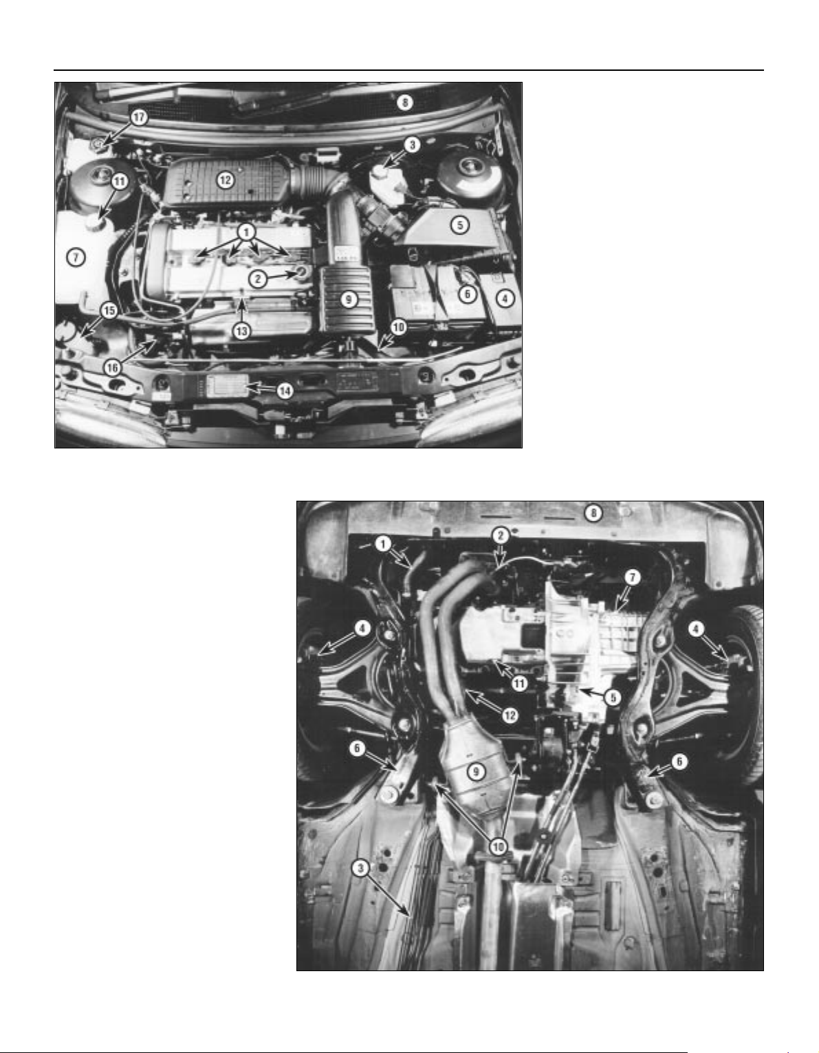
Engine compartment components
1 Spark plugs (Section 31)
2 Engine oil filler cap (Section 3)
3 Brake fluid reservoir (Section 3)
4 Auxiliary fusebox (Chapter 12)
5 Air cleaner assembly (Section 29)
6 Battery (Section 9)
7 Cooling system expansion tank
(Section 28)
8 Ventilation system pollen filter - under
cowl grille panel (Section 27)
9 Air intake resonator (Chapter 4)
10 Radiator top hose (Section 12)
11 Cooling system expansion tank filler cap
(Section 3)
12 Air intake plenum chamber (Chapter 4)
13 Engine oil dipstick (Section 3)
14 Vehicle Identification Number (VIN) plate
15 Windscreen/tailgate washer fluid reservoir
(Section 3)
16 Auxiliary drivebelt (Section 11)
17 Power steering fluid reservoir (Section 5)
Front underbody view
1 Radiator bottom hose (Section 12)
2 Exhaust gas oxygen sensor (Chapter 6)
3 Braking system, fuel and emission control
system lines (Section 22)
4 Front disc brake (Section 23)
5 Manual transmission drain plug
(Chapter 7, Part A)
6 Front suspension subframe (Chapter 2,
Part B)
7 Manual transmission filler/level plug
(Section 16)
8 Radiator undershield (Section 28)
9 Catalytic converter (Section 21)
10 Exhaust system rubber mountings
(Section 21)
11 Engine oil drain plug (Section 15)
12 Engine oil filter (Section 15)
Maintenance procedures
Page 19
1•5
1
Maintenance procedures
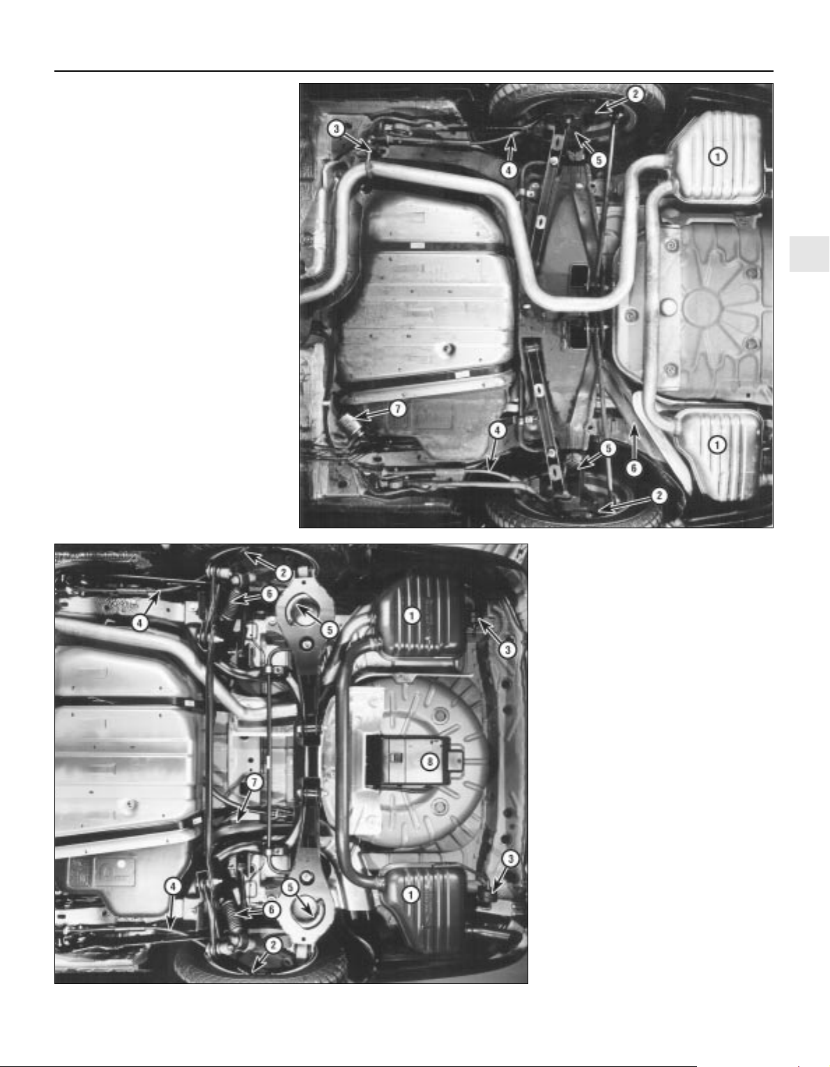
Rear underbody view - Saloon and
Hatchback models
1 Silencers (Section 21)
2 Rear brakes (Section 23)
3 Exhaust system rubber mounting
(Section 21)
4 Handbrake cables (Section 23)
5 Suspension struts and springs
(Section 19)
6 Fuel tank filler neck (Section 22)
7 Fuel filter (Section 33)
Rear underbody view - Estate models
1 Silencers (Section 21)
2 Rear brakes (Section 23)
3 Exhaust system rubber mounting
(Section 21)
4 Handbrake cables (Section 23)
5 Suspension springs (Section 19)
6 Suspension shock absorbers (Section 19)
7 Fuel tank filler neck (Section 22)
8 Evaporative emissions control system
charcoal canister (Chapter 6)
Page 20
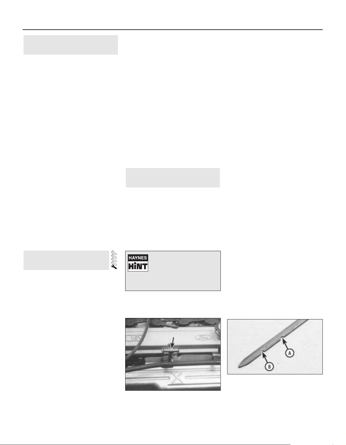
This Chapter is designed to help the home
mechanic maintain the Ford Mondeo models
for peak performance, economy, safety and
long life.
On the following pages are Sections
dealing specifically with each item on the
maintenance schedule. Visual checks,
adjustments, component replacement and
other helpful items are included. Refer to the
accompanying illustrations of the engine
compartment and the underside of the vehicle
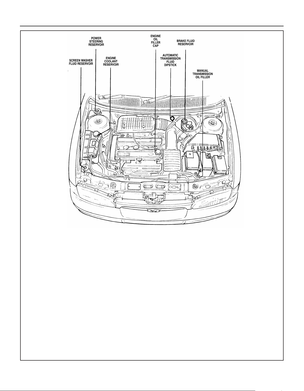
for the location of various components.
Servicing your Mondeo in accordance with
the mileage/time maintenance schedule and
the following Sections will provide it with a
planned maintenance programme, which
should result in a long and reliable service life.
This is a comprehensive plan, so maintaining
some items but not others at the specified
service intervals will not produce the same
results.
As you service your Mondeo, you will
discover that many of the procedures can and should - be grouped together, because of
the nature of the particular procedure you’re
performing, or because of the close proximity
to one another of two otherwise-unrelated
components.
For example, if the vehicle is raised for any
reason, you should inspect the exhaust,
suspension, steering and fuel systems while
you’re under the vehicle. When you’re
checking the tyres, it makes good sense to
check the brakes and wheel bearings,
especially if the roadwheels have already
been removed.
Finally, let’s suppose you have to borrow or
hire a torque wrench. Even if you only need to
tighten the spark plugs, you might as well
check the torque of as many critical fasteners
as time allows.
The first step of this maintenance
programme is to prepare yourself before the
actual work begins. Read through all the
Sections which are relevant to the procedures
you’re planning to carry out, then make a list
of, and gather together, all the parts and tools
you will need to do the job. If it looks as if you
might run into problems during a particular
segment of some procedure, seek advice
from your local parts man or dealer service
department.
Ford state that, where antifreeze to
specification ESD-M97B-49-A (the type with
which the vehicle’s cooling system would
have been filled on production at the factory)
is used, it will last the lifetime of the vehicle.
This is subject to it being used in the
recommended concentration, unmixed with
any other type of antifreeze or additive, and
topped-up when necessary using only that
antifreeze mixed 50/50 with clean water. If any
other type of antifreeze is added, the lifetime
guarantee no longer applies; to restore the
lifetime protection, the system must be
drained and thoroughly reverse-flushed
before fresh coolant mixture is poured in.
If the vehicle’s history (and therefore the
quality of the antifreeze in it) is unknown,
owners who wish to follow Ford’s
recommendations are advised to drain and
thoroughly reverse-flush the system, as
outlined in Section 28, before refilling with
fresh coolant mixture. If the appropriate
quality of antifreeze is used, the coolant can
then be left for the life of the vehicle.
If any antifreeze other than Ford’s is to be
used, the coolant must be renewed at regular
intervals to provide an equivalent degree of
protection; the conventional recommendation
is to renew the coolant every two years.
The above assumes the use of a mixture (in
exactly the specified concentration) of clean,
soft water and of antifreeze to Ford’s
specification or equivalent. It is also assumed
that the cooling system is maintained in a
scrupulously-clean condition, by ensuring that
only clean coolant is added on topping-up,
and by thorough reverse-flushing whenever
the coolant is drained (Section 28).
2 Coolant renewal
1 Introduction
1•6
Weekly checks
Weekly checks
General
1 Fluids are an essential part of the
lubrication, cooling, braking and other
systems. Because these fluids gradually
become depleted and/or contaminated during
normal operation of the vehicle, they must be
periodically replenished. See “Lubricants and
fluids and capacities” at the beginning of this
Chapter before adding fluid to any of the
following components. Note: The vehicle
must be on level ground before fluid levels can
be checked.
Engine oil
2 The engine oil level is checked with a
dipstick located at the front of the engine; it
can be identified by its yellow/black plastic
grip (see illustration). The dipstick extends
through a metal tube, from which it protrudes
down into the sump at the bottom of the
engine.
3 The oil level should be checked before the
vehicle is driven, or about 5 minutes after the
engine has been switched off.
4 Pull the dipstick from the tube, and wipe all
the oil from the end with a clean rag or paper
towel; note the dipstick’s maximum and
minimum levels, indicated by notches (see
illustration). Insert the clean dipstick all the way
back into its metal tube, and pull it out again.
Observe the oil on the end of the dipstick; its
level should be between these two notches.
5 Do not allow the level to drop below the
minimum level notch, or oil starvation may
cause engine damage. Conversely, overfilling
the engine (adding oil above the maximum
level notch) may cause oil-fouled spark plugs,
oil leaks or oil seal failures.
6 The yellow/black plastic oil filler cap is
screwed into the left-hand front end of the
3 Fluid level checks
3.2 The engine oil dipstick (arrowed) is
located at the front of the engine - note
yellow/black plastic grip
3.4 The oil level should be at or near the
maximum level notch (A) - if not, add
enough oil to correct the level. It takes
approximately 0.5 to 1.0 litre of oil to raise
the level from the minimum level notch (B)
to the maximum
If the level is checked
immediately after driving the
vehicle, some of the oil will
remain in the engine upper
components, producing an inaccurate
dipstick reading.
Page 21
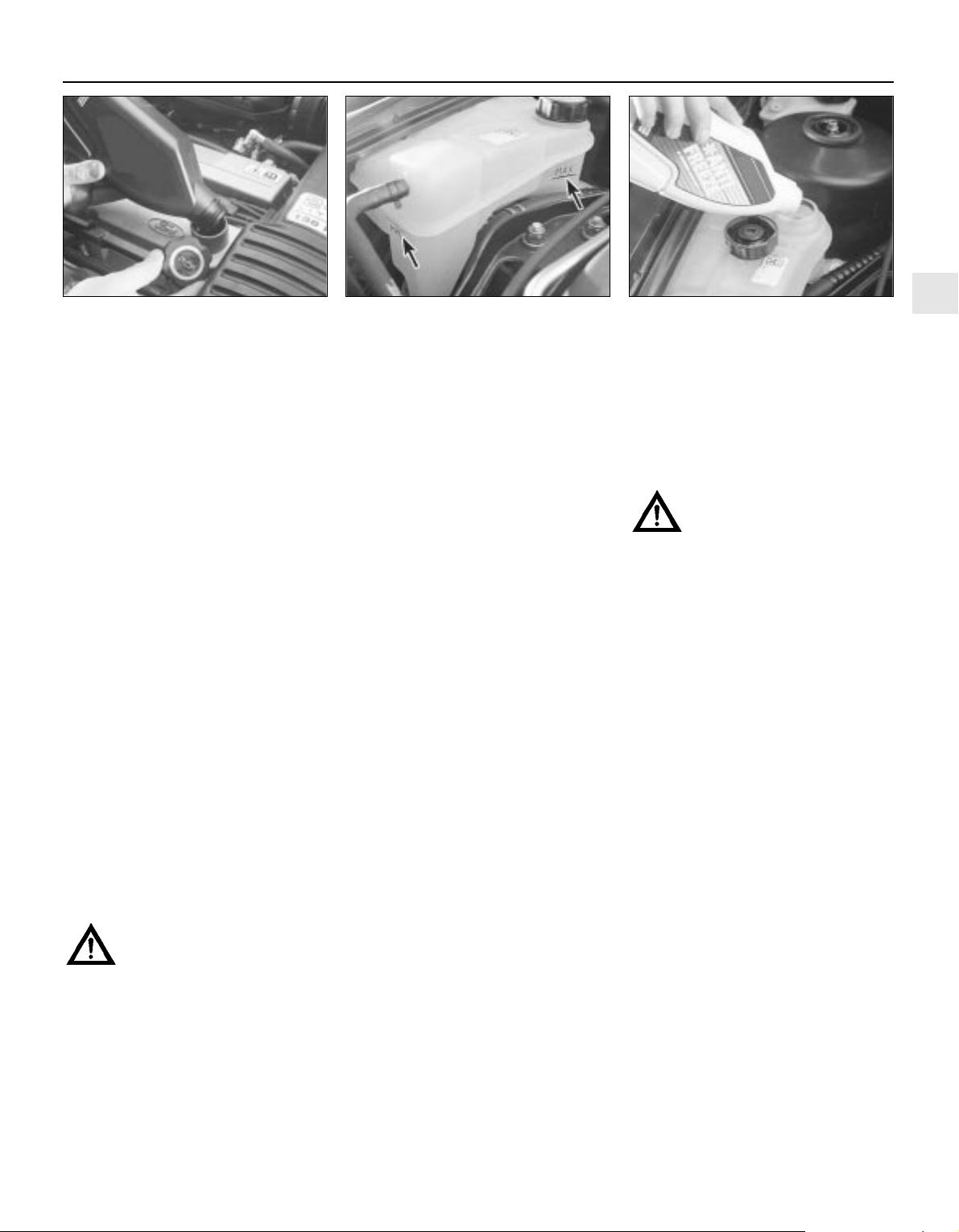
cylinder head cover; unscrew it to add oil (see
illustration). When topping-up, use only the
correct grade and type of oil, as given in the
Specifications Section of this Chapter; use a
funnel if necessary to prevent spills. It takes
approximately 0.5 to 1.0 litre of oil to raise the
level from the dipstick’s minimum level notch
to its maximum level notch. After adding the
oil, refit the filler cap hand-tight. Start the
engine, and allow it to idle while the oil is
redistributed around the engine - while you
are waiting, look carefully for any oil leaks,
particularly around the oil filter or drain plug.
Stop the engine; check the oil level again,
after the oil has had enough time to drain from
the upper block and cylinder head galleries.
7 Checking the oil level is an important
preventive maintenance step. A continuallydropping oil level indicates oil leakage through
damaged seals and from loose connections,
or oil consumption past worn piston rings or
valve guides. If the oil looks milky in colour, or
has water droplets in it, the cylinder head
gasket may be blown - the engine’s
compression pressure should be checked
immediately (see Chapter 2A). The condition
of the oil should also be checked. Each time
you check the oil level, slide your thumb and
index finger up the dipstick before wiping off
the oil. If you see small dirt or metal particles
clinging to the dipstick, the oil should be
changed (Section 15).
Coolant
Warning: Do not allow antifreeze
to come in contact with your skin
or painted surfaces of the
vehicle. Flush contaminated areas
immediately with plenty of water. Don’t
store new coolant, or leave old coolant
lying around, where it’s accessible to
children or pets - they’re attracted by its
sweet smell. Ingestion of even a small
amount of coolant can be fatal! Wipe up
garage-floor and drip-pan spills
immediately. Keep antifreeze containers
covered, and repair cooling system leaks
as soon as they’re noticed.
8 All vehicles covered by this manual are
equipped with a sealed, pressurised cooling
system. A translucent plastic expansion tank,
located on the right-hand side of the engine
compartment, is connected by a hose to the
thermostat housing. As the coolant heats up
during engine operation, surplus coolant
passes through the connecting hose into the
expansion tank; a connection to the radiator
bottom hose union allows coolant to circulate
through the tank and back to the water pump,
thus purging any air from the system. As the
engine cools, the coolant is automatically
drawn back into the cooling system’s main
components, to maintain the correct level.
9 While the coolant level must be checked
regularly, remember therefore that it will vary
with the temperature of the engine. When the
engine is cold, the coolant level should be
between the “MAX” and “MIN” level lines on
the tank, but once the engine has warmed up,
the level may rise to above the “MAX” level
line.
10 For an accurate check of the coolant
level, the engine must be cold. The level must
be between the “MAX” and “MIN” level lines
on the tank (see illustration). If it is below the
“MIN” level line, the coolant must be toppedup as follows.
11 First prepare a sufficient quantity of
coolant mixture, using clean, soft water and
antifreeze of the recommended type, in the
specified mixture ratio. If you are using
antifreeze to Ford’s specification or equivalent
(see the note at the beginning of Section 2 of
this Chapter), mix equal quantities of water
and antifreeze to produce the 50/50 mixture
ratio specified when topping-up; if using any
other type of antifreeze, follow its
manufacturer’s instructions to achieve the
correct ratio. If only a small amount of coolant
is required to bring the system up to the
proper level, plain water can be used, but
repeatedly doing this will dilute the
antifreeze/water solution in the system,
reducing the protection it should provide
against freezing and corrosion. To maintain
the specified antifreeze/water ratio, it is
essential to top-up the coolant level with the
correct mixture, as described here. Use only
ethylene/glycol type antifreeze, and do not
use supplementary inhibitors or additives.
Warning: Never remove the
expansion tank filler cap when
the engine is running, or has just
been switched off, as the cooling system
will be hot, and the consequent escaping
steam and scalding coolant could cause
serious injury.
12 If topping-up is necessary, wait until the
system has cooled completely (or at least 10
minutes after switching off the engine, if lack
of time means it is absolutely necessary to
top-up while the engine may still be warm).
Wrap a thick cloth around the expansion tank
filler cap, and unscrew it one full turn. If any
hissing is heard as steam escapes, wait until
the hissing ceases, indicating that pressure is
released, then slowly unscrew the filler cap
until it can be removed. If more hissing
sounds are heard, wait until they have
stopped before unscrewing the filler cap
completely. At all times, keep your face,
hands and other exposed skin well away from
the filler opening.
13 When the filler cap has been removed,
add coolant to bring the level up to the “MAX”
level line (see illustration). Refit the cap,
tightening it securely.
14 With this type of cooling system, the
addition of coolant should only be necessary at
very infrequent intervals. If topping-up is
regularly required, or if the coolant level drops
within a short time after replenishment, there
may be a leak in the system. Inspect the
radiator, hoses, expansion tank filler cap,
radiator drain plug and water pump. If no leak is
evident, have the filler cap and the entire
system pressure-tested by your dealer or
suitably-equipped garage; this will usually show
up a small leak not otherwise visible. If
significant leakage is found at any time, use an
antifreeze hydrometer to check the concentration of antifreeze remaining in the coolant.
1•7
1
3.13 Remove the cap to add coolant only
when the engine is cold - top-up to the
“MAX” level line using the specified
coolant mixture
3.6 The yellow/black oil filler cap is
screwed into the cylinder head cover.
Always make sure the area around the
opening is clean before unscrewing the
cap, to prevent dirt from contaminating the
engine
3.10 The cooling system expansion tank is
located on the right-hand side of the
engine compartment. The coolant level
must be between the tank “MAX” and
“MIN” level lines (arrowed) when the
engine is cold
Weekly checks
Page 22
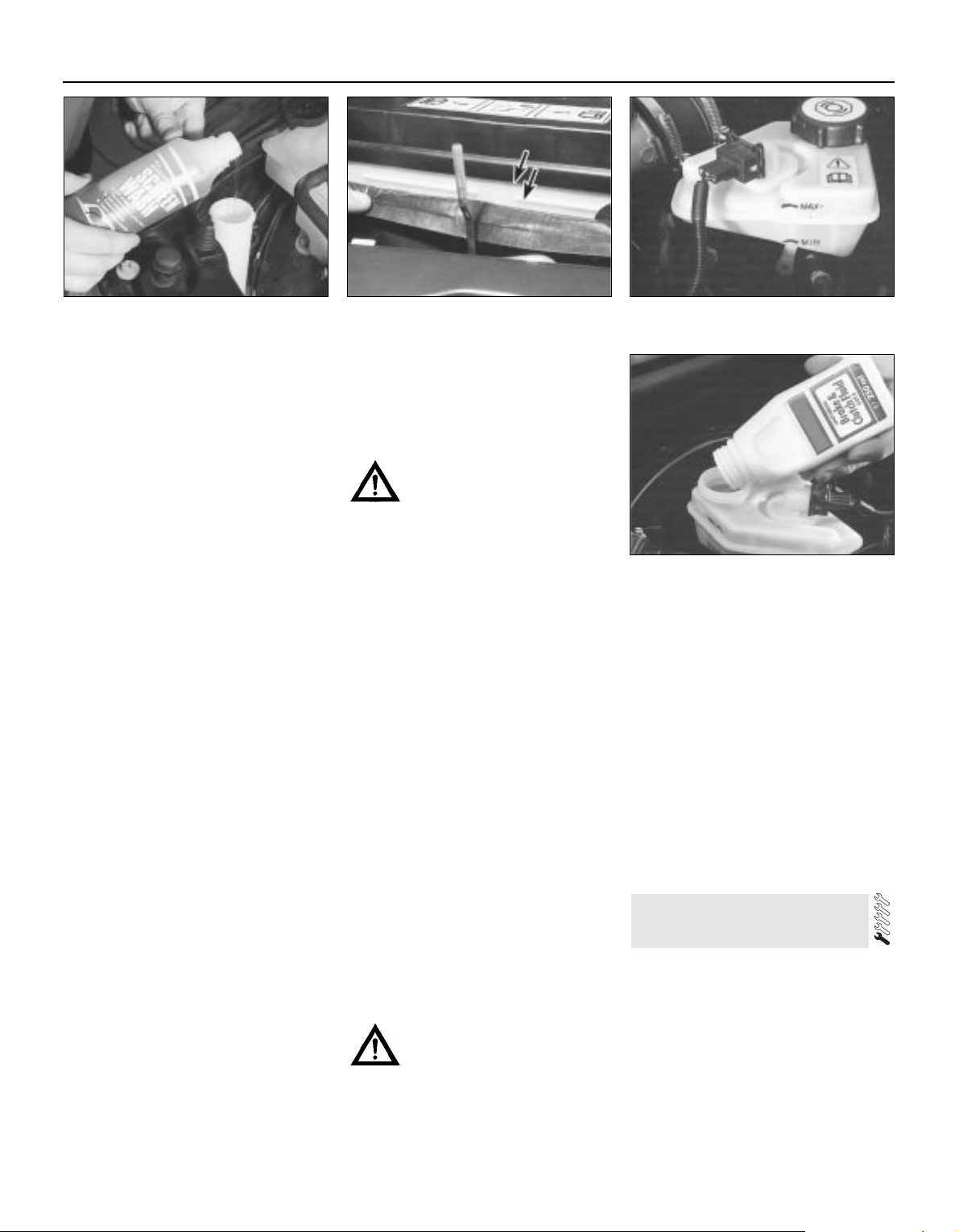
15 Coolant hydrometers are available at
most automotive accessory shops. If the
specific gravity of a sample taken from the
expansion tank (when the engine is switched
off and fully cooled down) is less than that
specified, the coolant mixture strength has
fallen below the minimum. If this is found,
either the coolant strength must be restored
by adding neat antifreeze to Ford’s
specification (if that is what is in the system)
or by draining and flushing the system, then
refilling it with fresh coolant mixture of the
correct ratio (if any other type of antifreeze is
being used).
16 When checking the coolant level, always
note its condition; it should be relatively clear.
If it is brown or rust-coloured, the system
should be drained, flushed and refilled. If
antifreeze has been used which does not
meet Ford’s specification, its corrosion
inhibitors will lose their effectiveness with
time; such coolant must be renewed regularly,
even if it appears to be in good condition,
usually at the intervals suggested at the
beginning of Section 2 of this Chapter.
Windscreen/tailgate and
headlight washer fluid
17 Fluid for the windscreen/tailgate washer
system (and where applicable the headlight
washer system) is stored in a plastic reservoir,
which is located at the right front corner of the
engine compartment. In milder climates, plain
water can be used to top-up the reservoir, but
the reservoir should be kept no more than
two-thirds full, to allow for expansion should
the water freeze. In colder climates, the use of
a specially-formulated windscreen washer
fluid, available at your dealer or any car
accessory shop, will help lower the freezing
point of the fluid (see illustration). Do not use
regular (engine) antifreeze - it will damage the
vehicle’s paintwork.
Battery electrolyte
18 On models not equipped with a sealed
battery (see Section 9), check the electrolyte
level of all six battery cells. The level must be
approximately 10 mm above the plates; this
may be shown by maximum and minimum
level lines marked on the battery’s casing (see
illustration). If the level is low, use a coin to
release the filler/vent cap, and add distilled
water. Install and securely retighten the cap.
Caution: Overfilling the cells may
cause electrolyte to spill over
during periods of heavy charging,
causing corrosion or damage.
Refer also to the warning at the beginning
of Section 9.
Brake fluid
19 The brake fluid reservoir is located on the
top of the brake master cylinder, which is
attached to the front of the vacuum servo unit.
The “MAX” and “MIN” marks are indicated on
the side of the translucent reservoir, and the
fluid level should be maintained between
these marks at all times (see illustration).
20 The brake fluid inside the reservoir is
readily visible. With the vehicle on level
ground, the level should normally be on or just
below the “MAX” mark.
21 Progressive wear of the brake pads and
brake shoe linings causes the level of the
brake fluid to gradually fall; however, when
the brake pads are renewed, the original level
of the fluid is restored. It is not therefore
necessary to top-up the level to compensate
for this minimal drop, but the level must never
be allowed to fall below the minimum mark.
22 If topping-up is necessary, first wipe the
area around the filler cap with a clean rag
before removing the cap. When adding fluid,
pour it carefully into the reservoir, to avoid
spilling it on surrounding painted surfaces
(see illustration). Be sure to use only the
specified hydraulic fluid (see “Lubricants,
fluids and capacities” at the start of this
Chapter) since mixing different types of fluid
can cause damage to the system.
Warning: Brake hydraulic fluid
can harm your eyes and damage
painted surfaces, so use extreme
caution when handling and
pouring it. Wash off spills immediately with
plenty of water. Do not use fluid that has
been standing open for some time, as it
absorbs moisture from the air. Excess
moisture can cause corrosion and a
dangerous loss of braking effectiveness.
23 When adding fluid, it is a good idea to
inspect the reservoir for contamination. The
system should be drained and refilled if
deposits, dirt particles or contamination are
seen in the fluid.
24 After filling the reservoir to the correct
level, make sure that the cap is refitted
securely, to avoid leaks and the entry of
foreign matter.
25 If the reservoir requires repeated
replenishing to maintain the correct level, this
is an indication of an hydraulic leak
somewhere in the system, which should be
investigated immediately.
Power steering fluid
26 See Section 5 of this Chapter.
1 Periodic inspection of the tyres may spare
you from the inconvenience of being stranded
with a flat tyre. It can also provide you with
vital information regarding possible problems
in the steering and suspension systems
before major damage occurs.
2 The original tyres on this vehicle are
equipped with tread wear indicator (TWI)
bands, which will appear when the tread
depth reaches approximately 1.6 mm. Most
tyres have a mark around the tyre at regular
intervals to indicate the location of the tread
4 Tyre and tyre pressure checks
1•8
3.17 Topping-up the windscreen washer
reservoir
3.18 On non-sealed batteries, keep the
electrolyte level of all the cells in the
battery between the maximum and
minimum levels (arrowed) - ie, 10 mm
above the plates. Use only distilled water,
and never overfill
3.19 Brake fluid reservoir, showing “MAX”
and “MIN” marks
3.22 Topping-up the brake fluid reservoir
Weekly checks
Page 23
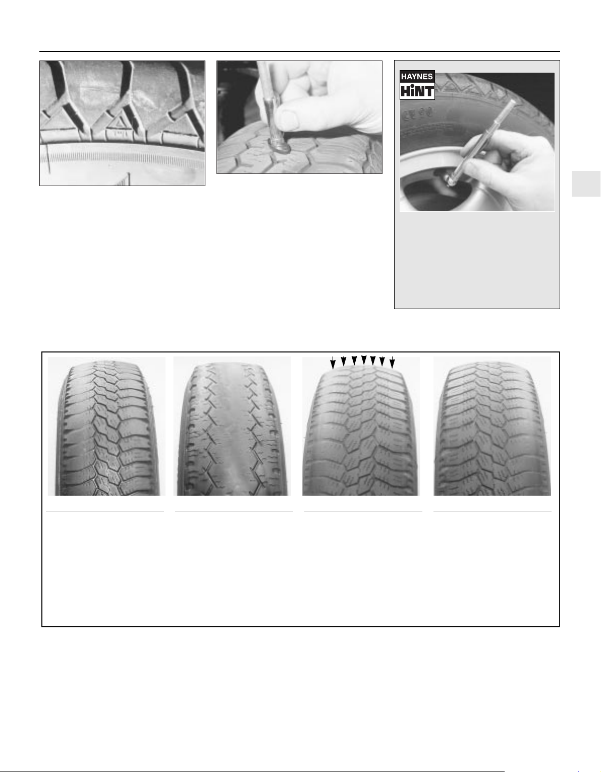
wear indicators, the mark being TWI, an
arrow, or the tyre manufacturer’s symbol (see
illustration). Tread wear can also be
monitored with a simple inexpensive device
known as a tread depth indicator gauge (see
illustration).
3 Ensure that tyre pressures are checked
regularly and maintained correctly (see the
Specifications at the beginning of this Chapter
for pressures). Checking should be carried out
with the tyres cold, and not immediately after
the vehicle has been in use. If the pressures
are checked with the tyres hot, an apparentlyhigh reading will be obtained, owing to heat
expansion. Under no circumstances should an
attempt be made to reduce the pressures to
the quoted cold reading in this instance, or
effective under-inflation will result.
1•9
1
Tyre Tread Wear Patterns
Shoulder Wear
Underinflation
(wear on both sides)
Check and adjust pressures
Incorrect wheel camber
(wear on one side)
Repair or renew suspension
parts
Hard cornering
Reduce speed!
Centre Wear
Overinflation
Check and adjust pressures
If you sometimes have to inflate
your car’s tyres to the higher
pressures specified for maximum
load or sustained high speed,
don’t forget to reduce the pressures to normal afterwards.
Toe Wear
Incorrect toe setting
Adjust front wheel alignment
Note: The feathered edge of
the tread which characterises
toe wear is best checked by
feel.
Uneven Wear
Incorrect camber or castor
Repair or renew suspension
parts
Malfunctioning suspension
Repair or renew suspension
parts
Unbalanced wheel
Balance tyres
Out-of-round brake disc/drum
Machine or renew
4.2A The TWI mark on the side of the tyre
shows the position of the tread wear
indicator bands
4.2B A tyre tread depth indicator should
be used to monitor tyre wear - they are
available at accessory shops and service
stations, and cost very little
Weekly checks
Most garage forecourts have a
pressure line which combines a gauge
to check and adjust the tyre pressures,
but they may vary in accuracy, due to
general misuse and abuse. It therefore
pays to carry a good-quality tyre
pressure gauge in the vehicle, to make
the regular checks required and ensure
pressure accuracy.
4 Note any abnormal tread wear (see
illustration). Tread pattern irregularities such
as feathering, flat spots, and more wear on
one side than the other, are indications of
front wheel alignment and/or balance
problems. If any of these conditions are
noted, they should be rectified as soon as
possible.
5 Under-inflation will cause overheating of the
tyre, owing to excessive flexing of the casing,
and the tread will not sit correctly on the road
surface. This will cause a consequent loss of
adhesion and excessive wear, not to mention
the danger of sudden tyre failure due to heat
build-up.
6 Over-inflation will cause rapid wear of the
centre part of the tyre tread, coupled with
reduced adhesion, harder ride, and the
danger of damage occurring in the tyre
casing.
7 Regularly check the tyres for damage in the
form of cuts or bulges, especially in the
sidewalls. Remove any nails or stones
embedded in the tread, before they penetrate
Page 24
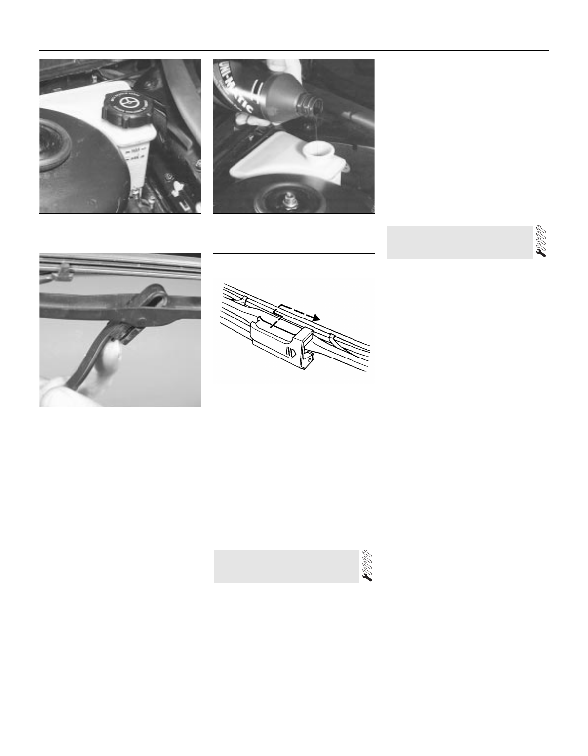
the tyre to cause deflation. If removal of a nail
reveals that the tyre has been punctured, refit
the nail, so that its point of penetration is
marked. Then immediately change the wheel,
and have the tyre repaired by a tyre dealer. Do
not drive on a tyre in such a condition. If in any
doubt as to the possible consequences of any
damage found, consult your local tyre dealer
for advice.
8 General tyre wear is influenced to a large
degree by driving style - harsh braking and
acceleration, or fast cornering, will all produce
more rapid tyre wear. Interchanging of tyres
may result in more even wear; however, it is
worth bearing in mind that if this is completely
effective, the added expense is incurred of
replacing simultaneously a complete set of
tyres, which may prove financially restrictive
for many owners.
9 Front tyres may wear unevenly as a result of
wheel misalignment. The front wheels should
always be correctly aligned according to the
settings specified by the vehicle
manufacturer.
10 Don’t forget to check the spare tyre for
condition and pressure.
11 Legal restrictions apply to many aspects
of tyre fitting and usage, and in the UK this
information is contained in the Motor Vehicle
Construction and Use Regulations. It is
suggested that a copy of these regulations is
obtained from your local police, if in doubt as
to current legal requirements with regard to
tyre type and condition, minimum tread depth,
etc.
1 The power steering fluid reservoir is located
on the right-hand rear corner of the engine
compartment.
2 For the fluid level check, the power steering
system should be at its normal operating
temperature, so it is best to carry out the
check after a run.
3 Position the vehicle on level ground, with
the front wheels pointing straight ahead, and
switch off the engine.
4 Check that the fluid level is up to the “MAX”
mark on the reservoir (see illustration).
5 If topping-up is required, first use a clean
rag to wipe the filler cap and the surrounding
area, to prevent foreign matter from entering
the system. Unscrew and remove the filler
cap.
6 Top-up the level to the “MAX” mark, using
the grade of fluid specified at the beginning of
this Chapter (see illustration). Be careful not
to introduce dirt into the system, and do not
overfill. The need for frequent topping-up
indicates a leak, which should be
investigated.
7 Refit the filler cap.
1 The windscreen wiper and blade assembly
should be inspected at the specified intervals
for damage, loose components, and cracked
or worn blade elements.
2 Road film can build up on the wiper blades
and affect their efficiency, so they should be
washed regularly with a mild detergent
solution.
3 The action of the wiping mechanism can
loosen bolts, nuts and fasteners, so they
should be checked and tightened, as
necessary, at the same time as the wiper
blades are checked.
4 If the wiper blade elements are cracked,
worn or warped, or no longer clean
adequately, they should be replaced with new
ones.
5 Lift the wiper arm and blade away from the
glass.
6 To remove the windscreen wiper blade,
release the catch on the arm, then turn the
blade through 90° and withdraw the blade
from the end of the arm (see illustration).
7 To remove the tailgate wiper blade, push
the wiper blade forward, and at the same time
depress it against the spring pressure, then
withdraw it from the end of the arm (see
illustration).
8 If the metal part of the wiper blade is in
good condition, it may be possible to renew
the rubber insert separately. The insert can be
obtained from a car accessory shop and,
according to type, it may need to be cut to the
correct length before sliding into the clips.
9 Refit the wiper blade assembly using a
reversal of the removal procedure, making
sure that it fully engages with the spring clip.
10 Check that the washer jets direct the fluid
onto the upper part of the
windscreen/tailgate/rear window/headlight,
and if necessary adjust the small sphere on
the jet with a pin.
6 Windscreen/tailgate washer
system and wiper blade check
5 Power steering fluid level
check
1•10
5.4 Power steering fluid reservoir,
showing “MAX” and “MIN” marks
5.6 Topping-up the power steering fluid
reservoir
6.7 Tailgate wiper blade removal
6.6 Releasing the catch to remove a
windscreen wiper blade
Weekly checks
Page 25
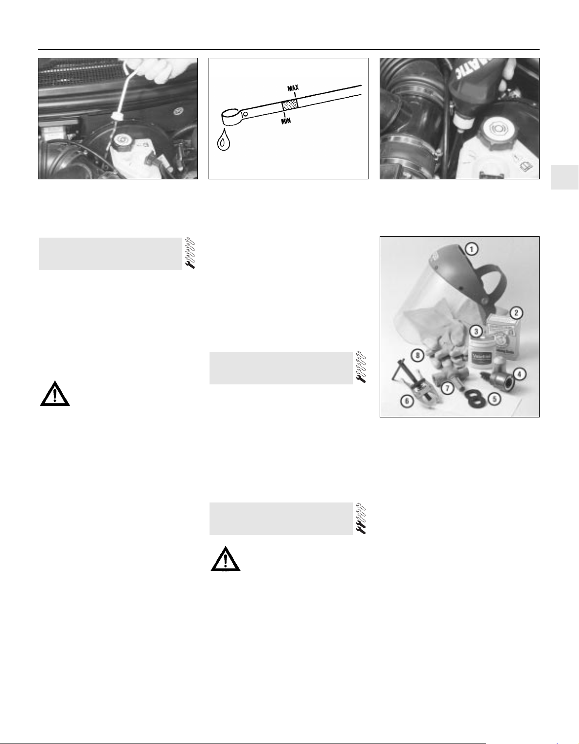
Every 10 000 miles or 12 months
1•11
1
7.4 Removing the automatic transmission
dipstick from its tube
7.6A “MIN” and “MAX” marks on the
dipstick
7.6B Adding automatic transmission fluid
through the dipstick tube
Every 10 000 miles
1 The level of the automatic transmission fluid
should be carefully maintained. Low fluid level
can lead to slipping or loss of drive, while
overfilling can cause foaming, loss of fluid and
transmission damage.
2 The transmission fluid level should only be
checked when the transmission is hot (at its
normal operating temperature). If the vehicle
has just been driven over 10 miles (15 miles in
a cold climate), and the fluid temperature is
160 to 175°F, the transmission is hot.
Caution: If the vehicle has just
been driven for a long time at
high speed or in city traffic in hot
weather, or if it has been pulling
a trailer, an accurate fluid level reading
cannot be obtained. In these
circumstances, allow the fluid to cool
down for about 30 minutes.
3 Park the vehicle on level ground, apply the
handbrake, and start the engine. While the
engine is idling, depress the brake pedal and
move the selector lever through all the gear
ranges three times, beginning and ending in
“P”.
4 Allow the engine to idle for one minute, then
(with the engine still idling) remove the dipstick
from its tube (see illustration). Note the
condition and colour of the fluid on the dipstick.
5 Wipe the fluid from the dipstick with a clean
rag, and re-insert it into the filler tube until the
cap seats.
6 Pull the dipstick out again, and note the
fluid level. The level should be between the
“MIN” and “MAX” marks. If the level is on the
“MIN” mark, stop the engine, and add the
specified automatic transmission fluid through
the dipstick tube, using a clean funnel if
necessary (see illustrations). It is important
not to introduce dirt into the transmission
when topping-up.
7 Add the fluid a little at a time, and keep
checking the level as previously described
until it is correct.
8 The need for regular topping-up of the
transmission fluid indicates a leak, which
should be found and rectified without delay.
9 The condition of the fluid should also be
checked along with the level. If the fluid at the
end of the dipstick is black or a dark reddishbrown colour, or if it has a burned smell, the
fluid should be changed. If you are in doubt
about the condition of the fluid, purchase
some new fluid, and compare the two for
colour and smell.
1 Check the operation of all external lights
and indicators (front and rear).
2 Check for satisfactory operation of the
instrument panel, its illumination and warning
lights, the switches and their function lights.
3 Check the horn(s) for satisfactory operation.
4 Check all other electrical equipment for
satisfactory operation.
5 Check all electrical wiring in the engine
compartment for correct routing, and for any
signs of physical or heat-damage or chafing.
Warning: Certain precautions
must be followed when checking
and servicing the battery.
Hydrogen gas, which is highly
flammable, is always present in the battery
cells, so keep lighted tobacco and all other
open flames and sparks away from the
battery. The electrolyte inside the battery
is actually dilute sulphuric acid, which will
cause injury if splashed on your skin or in
your eyes. It will also ruin clothes and
painted surfaces. When disconnecting the
battery, always detach the negative (earth)
lead first and connect it last!
Note: Before disconnecting the battery, refer
to Section 1 of Chapter 5.
9 Battery check, maintenance
and charging
8 Electrical system check
7 Automatic transmission fluid
level check
9.1 Tools and materials required for
battery maintenance
1 Face shield/safety goggles - When
removing corrosion with a brush, the acidic
particles can easily fly up into your eyes
2 Baking soda - A solution of baking soda
and water can be used to neutralise corrosion
3 Petroleum jelly - A layer of this on the
battery terminals will help prevent corrosion
4 Battery terminal/lead cleaner - This wire
brush cleaning tool will remove all traces of
corrosion from the battery terminals and lead
clamps
5 Treated felt washers - Placing one of
these on each terminal, directly under the
lead clamps, will help prevent corrosion
6 Puller - Sometimes the lead clamps are
very difficult to pull off the terminals, even
after the nut has been completely slackened.
This tool pulls the clamp straight up and off
the terminal without damage
7 Battery terminal/lead cleaner - Here is
another cleaning tool which is a slightly
different version of number 4 above, but does
the same thing
8 Rubber gloves - Another safety item to
consider when servicing the battery;
remember, that’s acid inside the battery!
Page 26
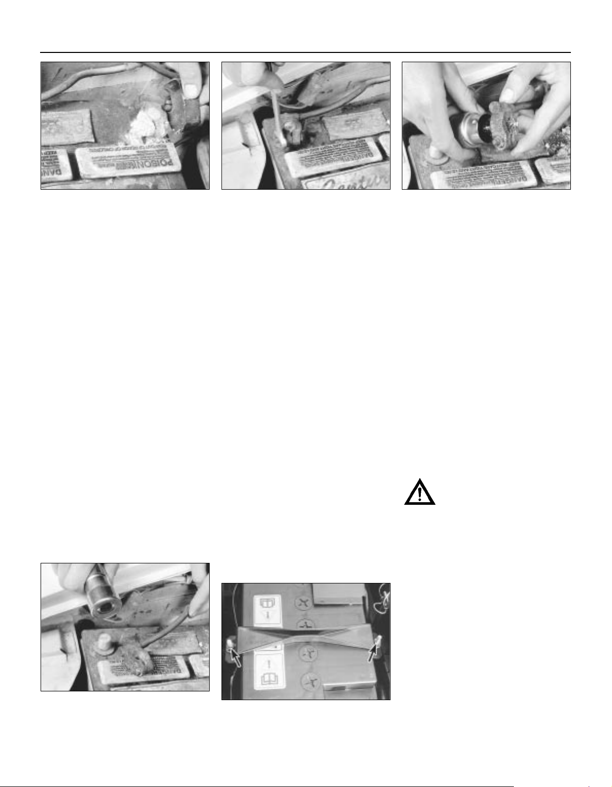
General
1 A routine preventive maintenance
programme for the battery in your vehicle is
the only way to ensure quick and reliable
starts. Before performing any battery
maintenance, make sure that you have the
proper equipment necessary to work safely
around the battery (see illustration).
2 There are also several precautions that
should be taken whenever battery
maintenance is performed. Before servicing
the battery, always turn the engine and all
accessories off, and disconnect the lead from
the negative terminal of the battery - see
Chapter 5, Section 1.
3 The battery produces hydrogen gas, which
is both flammable and explosive. Never create
a spark, smoke, or light a match around the
battery. Always charge the battery in a wellventilated area.
4 Electrolyte contains poisonous and
corrosive sulphuric acid. Do not allow it to get
in your eyes, on your skin, or on your clothes.
Never ingest it. Wear protective safety glasses
when working near the battery. Keep children
away from the battery.
5 Note the external condition of the battery. If
the positive terminal and lead clamp on your
vehicle’s battery is equipped with a plastic
cover or rubber protector, make sure that it’s
not torn or damaged. It should completely
cover the terminal. Look for any corroded or
loose connections, cracks in the case or
cover, or loose hold-down clamps. Also check
the entire length of each lead for cracks and
frayed conductors.
6 If corrosion, which looks like white, fluffy
deposits (see illustration) is evident,
particularly around the terminals, the battery
should be removed for cleaning. Slacken the
lead clamp nuts with a spanner, being careful
to remove the negative (earth) lead first, and
slide them off the terminals (see illustration).
Then unscrew the hold-down clamp nuts,
remove the clamp, and lift the battery from the
engine compartment.
7 Clean the lead clamps thoroughly, using a
soft wire brush or a terminal cleaner, with a
solution of warm water and baking soda.
Wash the terminals and the top of the battery
case with the same solution, but make sure
that the solution doesn’t get into the battery.
When cleaning the leads, terminals and
battery top, wear safety goggles and rubber
gloves, to prevent any solution from coming in
contact with your eyes or hands. Wear old
clothes too - even when diluted, sulphuric
acid splashed onto clothes will burn holes in
them. If the terminals have been extensively
corroded, clean them up with a terminal
cleaner (see illustrations). Thoroughly wash
all cleaned areas with plain water.
8 Make sure that the battery tray is in good
condition and the hold-down clamp nuts are
tight (see illustration). If the battery is
removed from the tray, make sure no parts
remain in the bottom of the tray when the
battery is refitted. When refitting the
hold-down clamp nuts, do not overtighten
them.
9 Information on removing and installing the
battery can be found in Chapter 5. Information
on jump starting can be found at the front of
this manual. For more detailed battery
checking procedures, refer to the Haynes
Automobile Electrical and Electronic Systems
Manual.
Cleaning
10 Corrosion on the hold-down components,
battery case and surrounding areas can be
removed with a solution of water and baking
soda. Thoroughly rinse all cleaned areas with
plain water.
11 Any metal parts of the vehicle damaged
by corrosion should be covered with a
zinc-based primer, then painted.
Charging
Warning: When batteries are
being charged, hydrogen gas,
which is very explosive and
flammable, is produced. Do not
smoke, or allow open flames, near a
charging or a recently-charged battery.
Wear eye protection when near the battery
during charging. Also, make sure the
charger is unplugged before connecting or
disconnecting the battery from the
charger.
12 Slow-rate charging is the best way to
restore a battery that’s discharged to the
point where it will not start the engine. It’s also
a good way to maintain the battery charge in a
vehicle that’s only driven a few miles between
starts. Maintaining the battery charge is
particularly important in winter, when the
battery must work harder to start the engine,
and electrical accessories that drain the
battery are in greater use.
13 It’s best to use a one- or two-amp battery
charger (sometimes called a “trickle” charger).
They are the safest, and put the least strain on
the battery. They are also the least expensive.
For a faster charge, you can use a higher-
1•12
9.6A Battery terminal corrosion usually
appears as light, fluffy powder
9.6B Removing a lead from the battery
terminal - always remove the earth lead
first, and connect it last!
9.7A When cleaning the lead clamps, all
corrosion must be removed - the inside of
the clamp is tapered to match the terminal,
so don’t remove too much material
9.7B Regardless of the method used to
clean the terminals, a clean, shiny surface
should result
9.8 Make sure the battery hold-down nuts
(arrowed) are tight
Every 10 000 miles
Page 27
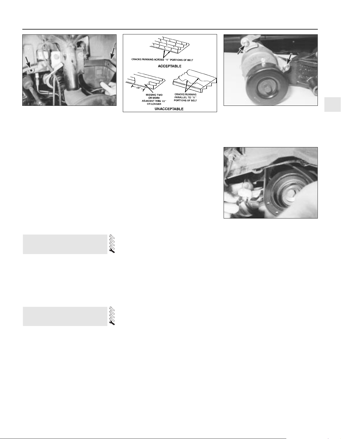
amperage charger, but don’t use one rated
more than 1/10th the amp/hour rating of the
battery (ie no more than 5 amps, typically).
Rapid boost charges that claim to restore the
power of the battery in one to two hours are
hardest on the battery, and can damage
batteries not in good condition. This type of
charging should only be used in emergency
situations.
14 The average time necessary to charge a
battery should be listed in the instructions that
come with the charger. As a general rule, a
trickle charger will charge a battery in 12 to
16 hours.
1 Check the seat belts for satisfactory
operation and condition. Inspect the webbing
for fraying and cuts. Check that they retract
smoothly and without binding into their reels.
2 Check that the seat belt mounting bolts are
tight, and if necessary tighten them to the
specified torque wrench setting.
General
1 The auxiliary drivebelt is of the flat, multiribbed (or “polyvee”) type, and is located on
the right-hand end of the engine. It drives the
alternator, water pump, power steering pump
and (when fitted) the air conditioning
compressor from the engine’s crankshaft
pulley.
2 The good condition and proper tension of
the auxiliary drivebelt is critical to the
operation of the engine. Because of their
composition and the high stresses to which
they are subjected, drivebelts stretch and
deteriorate as they get older. They must,
therefore, be regularly inspected.
Check
3 With the engine switched off, open and
support the bonnet, then locate the auxiliary
drivebelt on the right-hand end of the engine,
under the engine right-hand mounting
bracket. (Be very careful, and wear protective
gloves to minimise the risk of burning your
hands on hot components, if the engine has
recently been running.) For improved access,
jack up the front right-hand side of the
vehicle, support it securely on an axle stand,
remove the roadwheel, then remove the
auxiliary drivebelt cover (two fasteners) from
inside the wheel arch (see illustration).
4 Using an inspection light or a small electric
torch, and rotating the engine when necessary
with a spanner applied to the crankshaft
pulley bolt, check the whole length of the
drivebelt for cracks, separation of the rubber,
and torn or worn ribs (see illustration). Also
check for fraying and glazing, which gives the
drivebelt a shiny appearance. Both sides of
the drivebelt should be inspected, which
means you will have to twist the drivebelt to
check the underside. Use your fingers to feel
the drivebelt where you can’t see it. If you are
in any doubt as to the condition of the
drivebelt, renew it (go to paragraph 7).
Drivebelt tension
5 The auxiliary drivebelt is tensioned by an
automatic tensioner; regular checks are not
required, and manual “adjustment” is not
possible.
6 If you suspect that the drivebelt is slipping
and/or running slack, or that the tensioner is
otherwise faulty, it must be renewed. To do
this, remove the drivebelt as described below,
then unbolt the tensioner (two Torx-type
screws accessible from underneath, via the
wheel arch) from the alternator mounting
bracket (see illustration). On fitting the new
tensioner, ensure it is aligned correctly on its
mountings, and tighten the screws to the
specified torque wrench setting.
Renewal
7 Open the bonnet. Jack up the front righthand side of the vehicle and support it
securely on an axle stand, remove the
roadwheel, then remove the auxiliary drivebelt
cover (two fasteners) from inside the wheel
arch.
8 If the existing drivebelt is to be refitted,
mark it, or note the maker’s markings on its
flat surface, so that it can be installed the
same way round.
9 Reaching up between the body and the
engine (above and to the rear of the
crankshaft pulley), apply a spanner to the
hexagon in the centre of the automatic
tensioner’s pulley. Rotate the tensioner pulley
clockwise to release its pressure on the
drivebelt, then slip the drivebelt off the
crankshaft pulley, and release the tensioner
again (see illustration). Working from the
wheel arch or engine compartment as
necessary, and noting its routing, slip the
drivebelt off the remaining pulleys and
withdraw it.
10 Check all the pulleys, ensuring that their
grooves are clean, and removing all traces of
oil and grease. Check that the tensioner
works properly, with strong spring pressure
11 Auxiliary drivebelt check and
renewal
10 Seat belt check
1•13
1
11.9 Rotate the tensioner pulley clockwise
to release its pressure on the drivebelt,
then slip the drivebelt off the crankshaft
pulley
11.3 Removing the auxiliary drivebelt
cover - it is secured by a fastener at each
end (arrowed) - from inside the right-hand
front wheel arch
11.4 Check the auxiliary drivebelt for signs
of wear like these. Very small cracks across
the drivebelt ribs are acceptable. If the
cracks are deep, or if the drivebelt looks
worn or damaged in any other way, renew it
11.6 The auxiliary drivebelt is tensioned by
an automatic tensioner; Torx screws
(arrowed) secure it to alternator mounting
bracket
Every 10 000 miles
Page 28
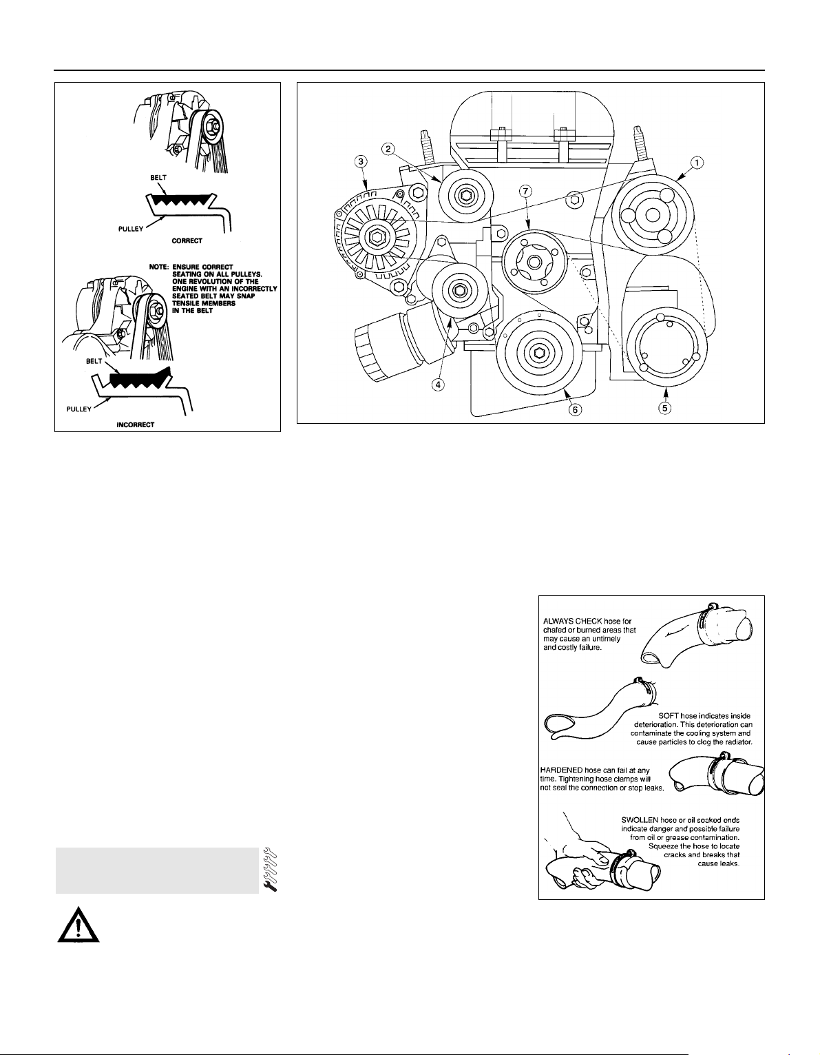
being felt when its pulley is rotated clockwise,
and a smooth return to the limit of its travel
when released.
11 If the original drivebelt is being refitted,
use the marks or notes made on removal, to
ensure that it is installed to run in the same
direction as it was previously. To fit the
drivebelt, arrange it on the grooved pulleys so
that it is centred in their grooves, and not
overlapping their raised sides (note that the
flat surface of the drivebelt is engaged on the
idler, tensioner and water pump pulleys) and
routed correctly (see illustrations). Start at
the top, and work down to finish at the
crankshaft pulley; rotate the tensioner pulley
clockwise, slip the drivebelt onto the
crankshaft pulley, then release the tensioner
again.
12 Using a spanner applied to the crankshaft
pulley bolt, rotate the crankshaft through at
least two full turns clockwise to settle the
drivebelt on the pulleys, then check that the
drivebelt is properly installed.
13 Refit the auxiliary drivebelt cover and
roadwheel, then lower the vehicle to the
ground.
Caution: Renewal of air
conditioning hoses must be left
to a dealer service department or
air conditioning specialist who has the
equipment to depressurise the system
safely. Never remove air conditioning
components or hoses until the system has
been depressurised.
General
1 High temperatures in the engine
compartment can cause the deterioration of
the rubber and plastic hoses used for engine,
accessory and emission systems operation.
Periodic inspection should be made for
cracks, loose clamps, material hardening and
leaks.
2 Carefully check the large top and bottom
radiator hoses, along with the other smallerdiameter cooling system hoses and metal
pipes; do not forget the heater hoses/pipes
which run from the engine to the bulkhead,
and those to the engine oil cooler (where
fitted). Inspect each hose along its entire
length, replacing any that is cracked, swollen
or shows signs of deterioration. Cracks may
become more apparent if the hose is
squeezed (see illustration). If you are using
non-Ford specification antifreeze, and so
have to renew the coolant every two years or
so, it’s a good idea to renew the hoses at that
time, regardless of their apparent condition.
3 Make sure that all hose connections are
tight. A leak in the cooling system will usually
show up as white- or rust-coloured deposits
on the areas adjoining the leak; if the spring
clamps that are used to secure the hoses in
this system appear to be slackening, they
should be renewed to prevent the possibility
of leaks.
4 Some other hoses are secured to their
fittings with clamps. Where clamps are used,
check to be sure they haven’t lost their
tension, allowing the hose to leak. If clamps
aren’t used, make sure the hose has not
expanded and/or hardened where it slips over
the fitting, allowing it to leak.
12 Underbonnet check for fluid
leaks and hose condition
1•14
11.11A When installing the auxiliary
drivebelt, make sure that it is centred - it
must not overlap either edge of the
grooved pulleys
11.11B Auxiliary drivebelt routing
1 Power steering pump
2 Idler pulley
3 Alternator
4 Automatic tensioner
5 Air conditioning
compressor (when fitted)
6 Crankshaft pulley
7 Water pump pulley
12.2 Hoses, like drivebelts, have a habit of
failing at the worst possible time - to
prevent the inconvenience of a blown
radiator or heater hose, inspect them
carefully as shown here
Every 10 000 miles
Page 29
5 Check all fluid reservoirs, filler caps, drain
plugs and fittings etc, looking for any signs of
leakage of oil, transmission and/or brake
hydraulic fluid, coolant and power steering
fluid. If the vehicle is regularly parked in the
same place, close inspection of the ground
underneath it will soon show any leaks; ignore
the puddle of water which will be left if the air
conditioning system is in use. As soon as a
leak is detected, its source must be traced
and rectified. Where oil has been leaking for
some time, it is usually necessary to use a
steam cleaner, pressure washer or similar, to
clean away the accumulated dirt, so that the
exact source of the leak can be identified.
Vacuum hoses
6 It’s quite common for vacuum hoses,
especially those in the emissions system, to
be colour-coded, or to be identified by
coloured stripes moulded into them. Various
systems require hoses with different wall
thicknesses, collapse resistance and
temperature resistance. When renewing
hoses, be sure the new ones are made of the
same material.
7 Often the only effective way to check a
hose is to remove it completely from the
vehicle. If more than one hose is removed, be
sure to label the hoses and fittings to ensure
correct installation.
8 When checking vacuum hoses, be sure to
include any plastic T-fittings in the check.
Inspect the fittings for cracks, and check the
hose where it fits over the fitting for distortion,
which could cause leakage.
9 A small piece of vacuum hose (quarter-inch
inside diameter) can be used as a
stethoscope to detect vacuum leaks. Hold
one end of the hose to your ear, and probe
around vacuum hoses and fittings, listening
for the “hissing” sound characteristic of a
vacuum leak.
Warning: When probing with the
vacuum hose stethoscope, be
very careful not to come into
contact with moving engine
components such as the auxiliary
drivebelt, radiator electric cooling fan, etc.
Fuel hoses
Warning: There are certain
precautions which must be taken
when inspecting or servicing fuel
system components. Work in a wellventilated area, and do not allow open
flames (cigarettes, appliance pilot lights,
etc.) or bare light bulbs near the work
area. Mop up any spills immediately, and
do not store fuel-soaked rags where they
could ignite.
10 Check all fuel hoses for deterioration and
chafing. Check especially for cracks in areas
where the hose bends, and also just before
fittings, such as where a hose attaches to the
fuel filter.
11 High-quality fuel line, usually identified by
the word “Fluoroelastomer” printed on the
hose, should be used for fuel line renewal.
Never, under any circumstances, use
unreinforced vacuum line, clear plastic tubing
or water hose for fuel lines.
12 Spring-type clamps are commonly used
on fuel lines. These clamps often lose their
tension over a period of time, and can be
“sprung” during removal. Replace all
spring-type clamps with screw clamps
whenever a hose is replaced.
Metal lines
13 Sections of metal piping are often used
for fuel line between the fuel filter and the
engine. Check carefully to be sure the piping
has not been bent or crimped, and that cracks
have not started in the line.
14 If a section of metal fuel line must be
renewed, only seamless steel piping should
be used, since copper and aluminium piping
don’t have the strength necessary to
withstand normal engine vibration.
15 Check the metal brake lines where they
enter the master cylinder and ABS hydraulic
unit (if used) for cracks in the lines or loose
fittings. Any sign of brake fluid leakage calls
for an immediate and thorough inspection of
the brake system.
1 With the vehicle parked on level ground,
apply the handbrake firmly and open the
bonnet. Using an inspection light or a small
electric torch, check all visible wiring within
and beneath the engine compartment.
2 What you are looking for is wiring that is
obviously damaged by chafing against sharp
edges, or against moving suspension/
transmission components and/or the auxiliary
drivebelt, by being trapped or crushed
between carelessly-refitted components, or
melted by being forced into contact with the
hot engine castings, coolant pipes, etc. In
almost all cases, damage of this sort is
caused in the first instance by incorrect
routing on reassembly after previous work has
been carried out.
3 Depending on the extent of the problem,
damaged wiring may be repaired by rejoining
the break or splicing-in a new length of wire,
using solder to ensure a good connection,
and remaking the insulation with adhesive
insulating tape or heat-shrink tubing, as
appropriate. If the damage is extensive, given
the implications for the vehicle’s future
reliability, the best long-term answer may well
be to renew that entire section of the loom,
however expensive this may appear.
4 When the actual damage has been
repaired, ensure that the wiring loom is rerouted correctly, so that it is clear of other
components, and not stretched or kinked, and
is secured out of harm’s way using the plastic
clips, guides and ties provided.
5 Check all electrical connectors, ensuring
that they are clean, securely fastened, and
that each is locked by its plastic tabs or wire
clip, as appropriate. If any connector shows
external signs of corrosion (accumulations of
white or green deposits, or streaks of “rust”),
or if any is thought to be dirty, it must be
unplugged and cleaned using electrical
contact cleaner. If the connector pins are
severely corroded, the connector must be
renewed; note that this may mean the renewal
of that entire section of the loom - see your
local Ford dealer for details.
6 If the cleaner completely removes the
corrosion to leave the connector in a
satisfactory condition, it would be wise to
pack the connector with a suitable material
which will exclude dirt and moisture,
preventing the corrosion from occurring
again; a Ford dealer may be able to
recommend a suitable product.
7 Check the condition of the battery
connections - remake the connections or
renew the leads if a fault is found (see Chapter 5). Use the same techniques to ensure that
all earth points in the engine compartment
provide good electrical contact through clean,
metal-to-metal joints, and that all are securely
fastened. (In addition to the earth connection
at the engine lifting eye, and that from the
transmission to the body/battery, there are
one or two earth points behind each headlight
assembly, and one below the power steering
fluid reservoir.)
8 Refer to Section 31 for details of spark plug
(HT) lead checks.
Warning: The air conditioning
system is under high pressure.
Do not loosen any fittings or
remove any components until
after the system has been discharged. Air
conditioning refrigerant must be properly
discharged into an approved type of
container, at a dealer service department
or an automotive air conditioning repair
facility capable of handling R134a
refrigerant. Always wear eye protection
when disconnecting air conditioning
system fittings.
1 The following maintenance checks should
be performed on a regular basis, to ensure
that the air conditioner continues to operate at
peak efficiency:
(a) Check the auxiliary drivebelt. If it’s worn
or deteriorated, renew it (see Section 11).
(b) Check the system hoses. Look for cracks,
bubbles, hard spots and deterioration.
Inspect the hoses and all fittings for oil
bubbles and seepage. If there’s any
evidence of wear, damage or leaks, renew
the hose(s).
(c) Inspect the condenser fins for leaves,
insects and other debris. Use a “fin
14 Air conditioning system
check
13 Engine compartment wiring
check
1•15
1
Every 10 000 miles
Page 30

comb” or compressed air to clean the
condenser.
Warning: Wear eye protection
when using compressed air!
(d) Check that the drain tube from the front
of the evaporator is clear - note that it is
normal to have clear fluid (water) dripping
from this while the system is in operation,
to the extent that quite a large puddle can
be left under the vehicle when it is parked.
2 It’s a good idea to operate the system for
about 30 minutes at least once a month,
particularly during the winter. Long term
non-use can cause hardening, and
subsequent failure, of the seals.
3 Because of the complexity of the air
conditioning system and the special
equipment necessary to service it, in-depth
fault diagnosis and repairs are not included in
this manual. For more complete information
on the air conditioning system, refer to the
Haynes Automotive Heating and Air
Conditioning Manual.
4 The most common cause of poor cooling is
simply a low system refrigerant charge. If a
noticeable drop in cool air output occurs, the
following quick check will help you determine
if the refrigerant level is low.
5 Warm the engine up to normal operating
temperature.
6 Place the air conditioning temperature
selector at the coldest setting, and put the
blower at the highest setting. Open the doors
- to make sure the air conditioning system
doesn’t cycle off as soon as it cools the
passenger compartment.
7 With the compressor engaged - the clutch
will make an audible click, and the centre of
the clutch will rotate - feel the inlet and outlet
pipes at the compressor. One side should be
cold, and one hot. If there’s no perceptible
difference between the two pipes, there’s
something wrong with the compressor or the
system. It might be a low charge - it might be
something else. Take the vehicle to a dealer
service department or an automotive air
conditioning specialist.
1 Make sure that you have all the necessary
tools before you begin this procedure (see
illustration). You should also have plenty of
rags or newspapers handy, for mopping up
any spills.
2 To avoid any possibility of scalding, and to
protect yourself from possible skin irritants
and other harmful contaminants in used
engine oils, it is advisable to wear gloves
when carrying out this work.
3 Access to the underside of the vehicle is
greatly improved if the vehicle can be lifted on
a hoist, driven onto ramps, or supported by
axle stands.
Warning: Do not work under a
vehicle which is supported only
by an hydraulic or scissors-type
jack, or by bricks, blocks of
wood, etc.
4 If this is your first oil change, get under the
vehicle and familiarise yourself with the
position of the engine oil drain plug, which is
located at the rear of the sump. The engine
and exhaust components will be warm during
the actual work, so try to anticipate any
potential problems while the engine and
accessories are cool.
5 The oil should preferably be changed when
the engine is still fully warmed-up to normal
operating temperature, just after a run (the
needle on the temperature gauge should be in
the “Normal” sector of the gauge); warm oil
and sludge will flow out more easily. Park the
vehicle on firm, level ground, apply the
handbrake firmly, then select 1st or reverse
gear (manual transmission) or the “P” position
(automatic transmission). Open the bonnet
and remove the engine oil filler cap from the
cylinder head cover, then remove the oil level
dipstick from its tube (see Section 3).
6 Raise the front of the vehicle, and support it
securely on axle stands. Remove the front
right-hand roadwheel to provide access to the
oil filter; if the additional working clearance is
required, remove also the auxiliary drivebelt
cover (two fasteners).
15 Engine oil and filter change
1•16
15.1 These tools are required when
changing the engine oil and filter
1 Drain pan - It should be fairly shallow in
depth, but wide to prevent spills
2 Rubber gloves - When removing the drain
plug and filter, it is inevitable that you will get
oil on your hands (the gloves will prevent
burns from hot oil)
3 Breaker bar - Sometimes the oil drain plug
is pretty tight, and a long breaker bar is
needed to loosen it
4 Socket - To be used with the breaker bar
or a ratchet (must be the correct size to fit the
drain plug)
5 Filter wrench - This is a metal band-type
wrench, which requires clearance around the
filter to be effective
6 Filter wrench - This type fits on the
bottom of the filter, and can be turned with a
ratchet or breaker bar (different size wrenches
are available for different types of filters)
15.7 Use the correct-size spanner or
socket to remove the oil drain plug and
avoid rounding it off
15.9 Since the oil filter is usually on very
tight, you’ll need a special wrench for
removal. DO NOT use the wrench to
tighten the new filter. Pack rag under the
filter before removal to minimise the mess
Every 10 000 miles
Frequent oil changes are the
best preventive maintenance
the home mechanic can give
the engine, because ageing
oil becomes diluted and contaminated,
which leads to premature engine wear.
Note: It is
antisocial and
illegal to dump
oil down the
drain. To find
the location of
your local oil
recycling bank,
call this
number free.
Page 31
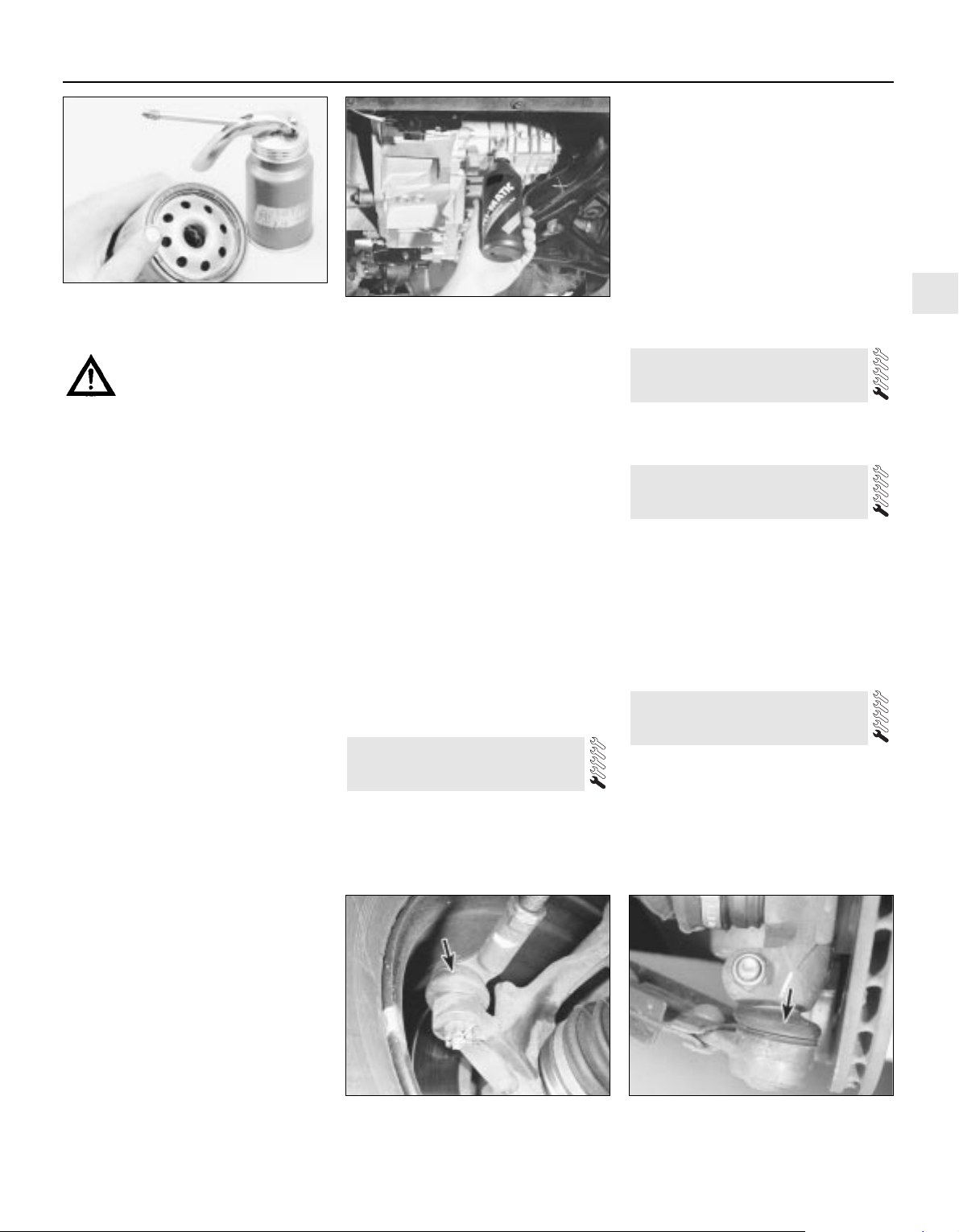
Warning: To avoid personal
injury, never get beneath the
vehicle when it is supported by
only by a jack. The jack provided
with your vehicle is designed solely for
raising the vehicle to remove and refit the
roadwheels. Always use axle stands to
support the vehicle when it becomes
necessary to place your body underneath
the vehicle.
7 Being careful not to touch the hot exhaust
components, place the drain pan under the
drain plug, and unscrew the plug (see
illustration). If possible, try to keep the plug
pressed into the sump while unscrewing it by
hand the last couple of turns. As the plug
releases from the threads, move it away
sharply, so the stream of oil issuing from the
sump runs into the pan, not up your sleeve!
Allow the oil to drain into the drain pan, and
check the condition of the plug’s sealing
washer; renew it if worn or damaged.
8 Allow some time for the old oil to drain,
noting that it may be necessary to reposition
the pan as the oil flow slows to a trickle; when
the oil has completely drained, wipe clean the
drain plug and its threads in the sump and
refit the plug, tightening it to the specified
torque wrench setting.
9 Using a suitable filter removal tool, unscrew
the oil filter from the right-hand rear of the
cylinder block; be prepared for some oil
spillage (see illustration). Check the old filter
to make sure that the rubber sealing ring
hasn’t stuck to the engine; if it has, carefully
remove it. Withdraw the filter through the
wheel arch, taking care to spill as little oil as
possible.
10 Using a clean, lint-free rag, wipe clean the
cylinder block around the filter mounting. If
there are no specific instructions supplied
with it, fit a new oil filter as follows. Apply a
light coating of clean engine oil to the filter’s
sealing ring (see illustration). Screw the filter
into position on the engine until it seats, then
tighten it through a further half- to threequarters of a turn only. Tighten the filter by
hand only - do not use any tools.
11 Remove the old oil and all tools from
under the vehicle, refit the roadwheel, and
lower the vehicle to the ground.
12 Refill the engine with oil, using the correct
grade and type of oil, as given in the
Specifications Section of this Chapter. Pour in
half the specified quantity of oil first, then wait
a few minutes for the oil to fall to the sump.
Continue adding oil a small quantity at a time,
until the level is up to the lower notch on the
dipstick. Adding approximately 0.5 to 1.0 litre
will raise the level to the dipstick’s upper
notch.
13 Start the engine. The oil pressure warning
light will take a few seconds to go out while
the new filter fills with oil; do not race the
engine while the light is on. Run the engine for
a few minutes, while checking for leaks
around the oil filter seal and the drain plug.
14 Switch off the engine, and wait a few
minutes for the oil to settle in the sump once
more. With the new oil circulated and the filter
now completely full, recheck the level on the
dipstick, and add more oil as necessary.
15 Dispose of the used engine oil safely, with
reference to “General repair procedures” in
the reference Sections of this manual.
1 The manual transmission does not have a
dipstick. To check the oil level, raise the
vehicle and support it securely on axle stands,
making sure that the vehicle is level. On the
lower front side of the transmission housing,
you will see the filler/level plug. Unscrew and
remove it. If the lubricant level is correct, the
oil should be up to the lower edge of the hole.
2 If the transmission needs more lubricant (if
the oil level is not up to the hole), use a
syringe, or a plastic bottle and tube, to add
more (see illustration). Stop filling the
transmission when the lubricant begins to run
out of the hole.
3 Refit the filler/level plug, and tighten it to the
specified torque wrench setting. Drive the
vehicle a short distance, then check for leaks.
4 A need for regular topping-up can only be
due to a leak, which should be found and
rectified without delay.
The procedure is described in Chapter 8,
Section 3.
1 Apply the handbrake, then jack up the front
of the vehicle and support on axle stands.
Remove the left-hand front wheel.
2 Apply a little oil to the cable end fitting on
the selector lever on the left-hand side of the
transmission (refer to Chapter 7, Part B if
necessary).
3 Refit the wheel, and lower the vehicle to the
ground.
Front suspension and steering
check
1 Apply the handbrake, then raise the front of
the vehicle and support it on axle stands.
2 Visually inspect the balljoint dust covers
and the steering gear gaiters for splits, chafing
or deterioration (see illustrations). Any wear
19 Steering, suspension and
roadwheel check
18 Automatic transmission
linkage lubrication
17 Clutch pedal adjustment
16 Manual transmission oil level
check
1•17
1
19.2B Check the condition of the lower
arm balljoint dust cover (arrowed)
15.10 Lubricate the filter’s sealing ring
with clean engine oil before installing the
filter on the engine
16.2 Topping-up the manual transmission
oil
19.2A Check the condition of the track rod
balljoint dust cover (arrowed)
Every 10 000 miles
Page 32
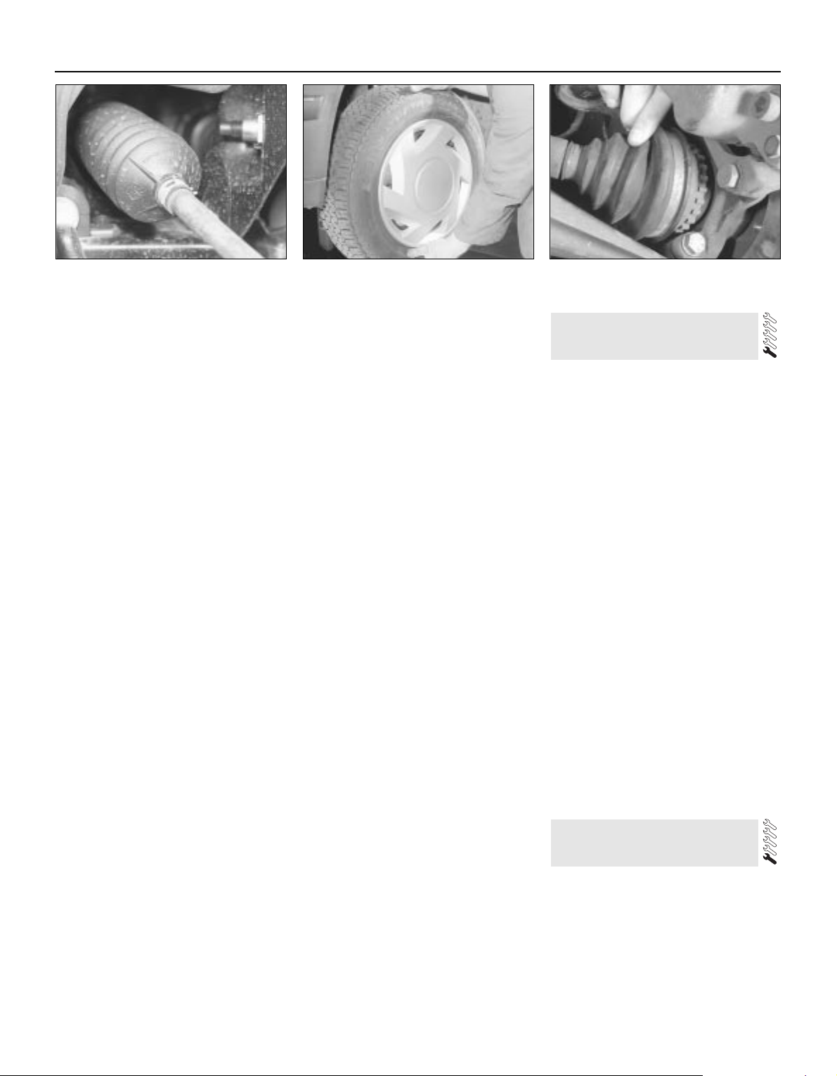
of these components will cause loss of
lubricant, together with dirt and water entry,
resulting in rapid deterioration of the balljoints
or steering gear.
3 Check the power-assisted steering fluid
hoses for chafing or deterioration, and the
pipe and hose unions for fluid leaks. Also
check for signs of fluid leakage under
pressure from the steering gear rubber
gaiters, which would indicate failed fluid seals
within the steering gear.
4 Grasp the roadwheel at the 12 o’clock and
6 o’clock positions, and try to rock it (see
illustration). Very slight free play may be felt,
but if the movement is appreciable, further
investigation is necessary to determine the
source. Continue rocking the wheel while an
assistant depresses the footbrake. If the
movement is now eliminated or significantly
reduced, it is likely that the hub bearings are
at fault. If the free play is still evident with the
footbrake depressed, then there is wear in the
suspension joints or mountings.
5 Now grasp the wheel at the 9 o’clock and
3 o’clock positions, and try to rock it as
before. Any movement felt now may again be
caused by wear in the hub bearings or the
steering track rod balljoints. If the outer track
rod balljoint is worn, the visual movement will
be obvious. If the inner joint is suspect, it can
be felt by placing a hand over the rack-andpinion rubber gaiter, and gripping the track
rod. If the wheel is now rocked, movement will
be felt at the inner joint if wear has taken
place.
6 Using a large screwdriver or flat bar, check
for wear in the suspension mounting bushes
by levering between the relevant suspension
component and its attachment point. Some
movement is to be expected as the mountings
are made of rubber, but excessive wear
should be obvious. Also check the condition
of any visible rubber bushes, looking for splits,
cracks or contamination of the rubber.
7 With the vehicle standing on its wheels,
have an assistant turn the steering wheel
back-and-forth, about an eighth of a turn each
way. There should be very little, if any, lost
movement between the steering wheel and
roadwheels. If this is not the case, closely
observe the joints and mountings previously
described, but in addition, check the steering
column universal joints for wear, and also
check the rack-and-pinion steering gear itself.
Rear suspension check
8 Chock the front wheels, then raise the rear
of the vehicle and support it on axle stands.
9 Check the rear hub bearings for wear, using
the method described for the front hub
bearings (paragraph 4).
10 Using a large screwdriver or flat bar,
check for wear in the suspension mounting
bushes by levering between the relevant
suspension component and its attachment
point. Some movement is to be expected as
the mountings are made of rubber, but
excessive wear should be obvious.
Roadwheel check and balancing
11 Periodically remove the roadwheels, and
clean any dirt or mud from the inside and
outside surfaces. Examine the wheel rims for
signs of rusting, corrosion or other damage.
Light alloy wheels are easily damaged by
“kerbing” whilst parking, and similarly, steel
wheels may become dented or buckled.
Renewal of the wheel is very often the only
course of remedial action possible.
12 The balance of each wheel and tyre
assembly should be maintained, not only to
avoid excessive tyre wear, but also to avoid
wear in the steering and suspension
components. Wheel imbalance is normally
signified by vibration through the vehicle’s
bodyshell, although in many cases it is
particularly noticeable through the steering
wheel. Conversely, it should be noted that
wear or damage in suspension or steering
components may cause excessive tyre wear.
Out-of-round or out-of-true tyres, damaged
wheels and wheel bearing wear/
maladjustment also fall into this category.
Balancing will not usually cure vibration
caused by such wear.
13 Wheel balancing may be carried out with
the wheel either on or off the vehicle. If
balanced on the vehicle, ensure that the
wheel-to-hub relationship is marked in some
way prior to subsequent wheel removal, so
that it may be refitted in its original position.
1 The driveshaft rubber gaiters are very
important, because they prevent dirt, water
and foreign material from entering and
damaging the constant velocity (CV) joints.
External contamination can cause the gaiter
material to deteriorate prematurely, so it’s a
good idea to wash the gaiters with soap and
water occasionally.
2 With the vehicle raised and securely
supported on axle stands, turn the steering
onto full-lock, then slowly rotate each front
wheel in turn. Inspect the condition of the
outer constant velocity (CV) joint rubber
gaiters, squeezing the gaiters to open out the
folds. Check for signs of cracking, splits, or
deterioration of the rubber, which may allow
the escape of grease, and lead to the ingress
of water and grit into the joint (see
illustration). Also check the security and
condition of the retaining clips. Repeat these
checks on the inner CV joints. If any damage
or deterioration is found, the gaiters should be
renewed as described in Chapter 8.
3 At the same time, check the general
condition of the outer CV joints themselves,
by first holding the driveshaft and attempting
to rotate the wheels. Repeat this check on the
inner joints, by holding the inner joint yoke
and attempting to rotate the driveshaft.
4 Any appreciable movement in the CV joint
indicates wear in the joint, wear in the
driveshaft splines, or a loose driveshaft
retaining nut.
1 With the engine cold (at least three hours
after the vehicle has been driven), check the
complete exhaust system, from its starting
point at the engine to the end of the tailpipe.
Ideally, this should be done on a hoist, where
unrestricted access is available; if a hoist is
not available, raise and support the vehicle on
axle stands.
2 Check the pipes and connections for
21 Exhaust system check
20 Driveshaft rubber gaiter and
CV joint check
1•18
19.2C Check the condition of the steering
rack gaiters
19.4 Checking for wear in the front
suspension and hub bearings
20.2 Check the driveshaft gaiters by hand
for cracks and/or leaking grease
Every 10 000 miles
Page 33
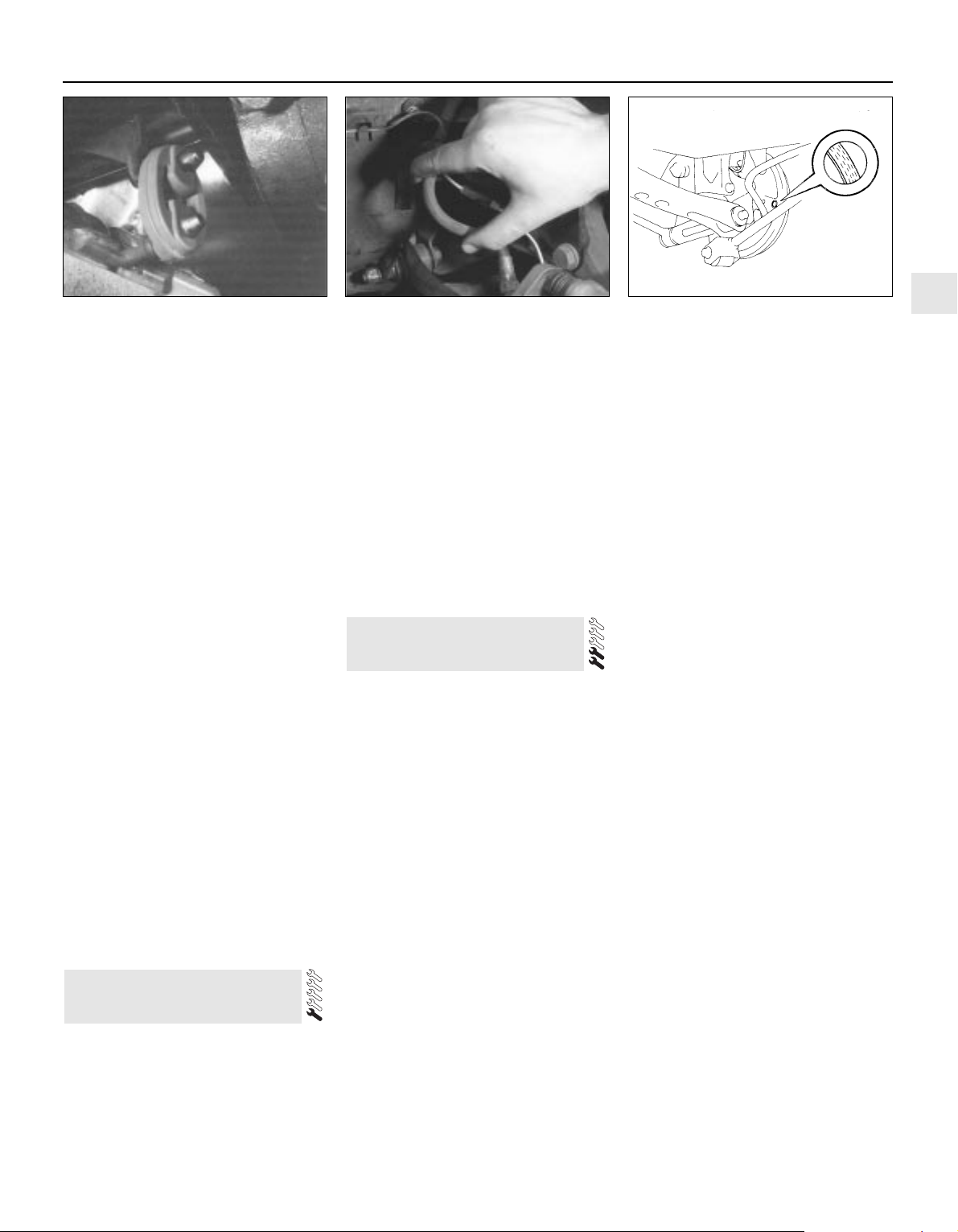
evidence of leaks, severe corrosion, or
damage. Make sure that all brackets and
rubber mountings are in good condition, and
tight; if any of the mountings are to be
renewed, ensure that the replacements are of
the correct type (see illustration). Leakage at
any of the joints or in other parts of the system
will usually show up as a black sooty stain in
the vicinity of the leak. Note: Exhaust sealants
should not be used on any part of the exhaust
system upstream of the catalytic converter even if the sealant does not contain additives
harmful to the converter, pieces of it may
break off and foul the element, causing local
overheating.
3 At the same time, inspect the underside of
the body for holes, corrosion, open seams,
etc. which may allow exhaust gases to enter
the passenger compartment. Seal all body
openings with silicone or body putty.
4 Rattles and other noises can often be
traced to the exhaust system, especially the
rubber mountings. Try to move the system,
silencer(s) and catalytic converter. If any
components can touch the body or
suspension parts, secure the exhaust system
with new mountings.
5 Check the running condition of the engine
by inspecting inside the end of the tailpipe;
the exhaust deposits here are an indication of
the engine’s state of tune. The inside of the
tailpipe should be dry, and should vary in
colour from dark grey to light grey/brown; if it
is black and sooty, or coated with white
deposits, the engine is in need of a thorough
fuel system inspection.
1 With the vehicle raised and supported on
axle stands or over an inspection pit,
thoroughly inspect the underbody and wheel
arches for signs of damage and corrosion. In
particular, examine the bottom of the side
sills, and any concealed areas where mud can
collect. Where corrosion and rust is evident,
press and tap firmly on the panel with a
screwdriver, and check for any serious
corrosion which would necessitate repairs. If
the panel is not seriously corroded, clean
away the rust, and apply a new coating of
underseal. Refer to Chapter 11 for more
details of body repairs.
2 At the same time, inspect the PVC-coated
lower body panels for stone damage and
general condition.
3 Inspect all of the fuel and brake lines on the
underbody for damage, rust, corrosion and
leakage. Also make sure that they are
correctly supported in their clips. Where
applicable, check the PVC coating on the
lines for damage.
Note: For detailed photographs of the brake
system, refer to Chapter 9.
1 The work described in this Section should
be carried out at the specified intervals, or
whenever a defect is suspected in the braking
system. Any of the following symptoms could
indicate a potential brake system defect:
(a) The vehicle pulls to one side when the
brake pedal is depressed.
(b) The brakes make scraping or dragging
noises when applied.
(c) Brake pedal travel is excessive.
(d) The brake fluid requires repeated topping-
up.
2 A brake pad wear warning light is fitted, and
it is illuminated when the thickness of the front
(or rear) disc brake pad linings reach the
minimum amount. However, a physical check
should be made to confirm the thickness of
the linings, as follows.
Disc brakes
3 Jack up the front or rear of the vehicle, as
applicable, and support it on axle stands.
Where rear brake pads are fitted, also jack up
the rear of the vehicle and support on axle
stands.
4 For better access to the brake calipers,
remove the wheels.
5 Look through the inspection window in the
caliper, and check that the thickness of the
friction lining material on each of the pads is
not less than the recommended minimum
thickness given in the Specifications. Note:
Bear in mind that the lining material is normally
bonded to a metal backing plate.
6 If it is difficult to determine the exact
thickness of the pad linings, or if you are at all
concerned about the condition of the pads,
then remove them from the calipers for further
inspection (refer to Chapter 9).
7 Check the remaining brake caliper(s) in the
same way.
8 If any one of the brake pads has worn down
to, or below, the specified limit, all four pads
at that end of the car must be renewed as a
set (ie all the front pads or all the rear pads).
9 Measure the thickness of the discs with a
micrometer, if available, to make sure that
they still have service life remaining. If any
disc is thinner than the specified minimum
thickness, renew it (refer to Chapter 9). In any
case, check the general condition of the
discs. Look for excessive scoring and
discolouration caused by overheating. If these
conditions exist, remove the relevant disc and
have it resurfaced or renewed (refer to
Chapter 9).
10 Before refitting the wheels, check all
brake lines and hoses (refer to Chapter 9). In
particular, check the flexible hoses in the
vicinity of the calipers, where they are
subjected to most movement. Bend them
between the fingers (but do not actually bend
them double, or the casing may be damaged)
and check that this does not reveal
previously-hidden cracks, cuts or splits (see
illustration).
Rear drum brakes
11 Chock the front wheels, then jack up the
rear of the vehicle and support on axle stands.
12 For better access, remove the rear
wheels.
13 To check the brake shoe lining thickness
without removing the brake drums, prise the
rubber plugs from the backplates, and use an
electric torch to inspect the linings of the
leading brake shoes (see illustration). Check
that the thickness of the lining material on the
23 Brake check
22 Underbody and fuel/brake
line check
1•19
1
21.2 If any of the exhaust system rubber
mountings are to be renewed, ensure that
the replacements are of the correct type -
their colour is a good guide. Those nearest
to the catalytic converter are more heat-
resistant than the others
23.10 Checking the condition of a flexible
brake hose
23.13 Prise the rubber plugs from the
backplates to inspect the leading brake
shoe linings
Every 000 miles
Page 34
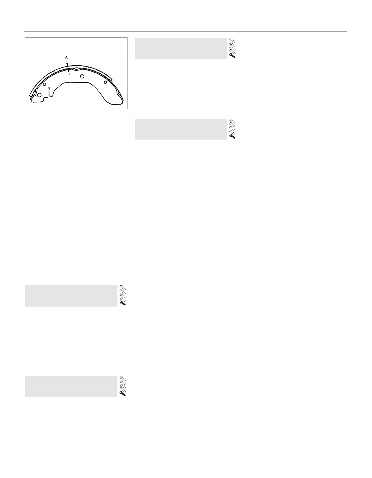
brake shoes is not less than the
recommendation given in the Specifications.
14 If it is difficult to determine the exact
thickness of the brake shoe linings, or if you
are at all concerned about the condition of the
shoes, then remove the rear drums for a more
comprehensive inspection (refer to Chapter 9)
(see illustration).
15 With the drum removed, check the shoe
return and hold-down springs for correct
installation, and check the wheel cylinders for
leakage of brake fluid. Check the friction
surface of the brake drums for scoring and
discoloration. If excessive, the drum should
be resurfaced or renewed.
16 Before refitting the wheels, check all
brake lines and hoses (refer to Chapter 9). On
completion, apply the handbrake and check
that the rear wheels are locked. The
handbrake is self-adjusting, and no manual
adjustment is possible.
1 Check that the doors, bonnet and
tailgate/boot lid close securely. Check that
the bonnet safety catch operates correctly.
Check the operation of the door check straps.
2 Lubricate the hinges, door check straps,
the striker plates and the bonnet catch
sparingly with a little oil or grease.
1 Apply the handbrake.
2 Remove the wheel covers, using the flat
end of the wheelbrace supplied in the tool kit
(on models with the RS trim kit, it will be
necessary to unscrew the retaining bolts with
the special key).
3 Check that the roadwheel nuts are tightened
to the specified torque wrench setting.
4 Refit the wheel covers.
Check the operation and
performance of the braking
system
1 Make sure that the vehicle does not pull to
one side when braking, and that the wheels
do not lock prematurely when braking hard.
2 Check that there is no vibration through the
steering when braking.
3 Check that the handbrake operates
correctly, without excessive movement of the
lever, and that it holds the vehicle stationary
on a slope.
4 With the engine switched off, test the
operation of the brake servo unit as follows.
Depress the footbrake four or five times to
exhaust the vacuum, then start the engine. As
the engine starts, there should be a noticeable
“give” in the brake pedal as vacuum builds
up. Allow the engine to run for at least two
minutes, and then switch it off. If the brake
pedal is now depressed again, it should be
possible to detect a hiss from the servo as the
pedal is depressed. After about four or five
applications, no further hissing should be
heard, and the pedal should feel considerably
harder.
Steering and suspension
5 Check for any abnormalities in the steering,
suspension, handling or road “feel”.
6 Drive the vehicle, and check that there are
no unusual vibrations or noises.
7 Check that the steering feels positive, with
no excessive sloppiness or roughness, and
check for any suspension noises when
cornering and driving over bumps.
Drivetrain
8 Check the performance of the engine,
transmission and driveshafts.
9 Check that the engine starts correctly, both
when cold and when hot.
10 Listen for any unusual noises from the
engine and transmission.
11 Make sure that the engine runs smoothly
when idling, and that there is no hesitation
when accelerating.
12 On manual transmission models, check
that all gears can be engaged smoothly
without noise, and that the gear lever action is
not abnormally vague or “notchy”.
13 On automatic transmission models, make
sure that all gearchanges occur smoothly
without snatching, and without an increase in
engine speed between changes. Check that
all the gear positions can be selected with the
vehicle at rest. If any problems are found, they
should be referred to a Ford dealer.
14 Listen for a metallic clicking sound from
the front of the vehicle as the vehicle is driven
slowly in a circle with the steering on full-lock.
Carry out this check in both directions. If a
clicking noise is heard, this indicates wear in a
driveshaft joint, in which case renew the joint
if necessary.
Clutch
15 Check that the clutch pedal moves
smoothly and easily through its full travel, and
that the clutch itself functions correctly, with
no trace of slip or drag. If the movement is
uneven or stiff in places, check that the cable
is routed correctly, with no sharp turns.
16 Inspect both ends of the clutch inner
cable, both at the gearbox end and inside the
car, for signs of wear and fraying.
17 Check the pedal stroke as described in
Chapter 8, Section 3, and adjust if necessary.
Instruments and electrical
equipment
18 Check the operation of all instruments
and electrical equipment.
19 Make sure that all instruments read
correctly, and switch on all electrical
equipment in turn, to check that it functions
properly.
26 Road test
25 Roadwheel nut tightness
check
24 Door and bonnet check and
lubrication
1•20
23.14 If the lining is bonded to the brake
shoe, measure the lining thickness from
the outer surface to the metal shoe, as
shown here; if the lining is riveted to the
shoe, measure from the lining outer
surface to the rivet head
Every 20 000 miles
Every 20 000 miles or 2 years
1 The air entering the vehicle’s ventilation
system is passed through a very fine pleatedpaper air filter element, which removes
particles of pollen, dust and other airborne
foreign matter. To ensure its continued
effectiveness, this filter’s element must be
renewed at regular intervals.
2 Remove the left-hand side windscreen
wiper arm (Chapter 12).
3 Prise off their trim caps, then unscrew the two
screws securing the windscreen edge of the cowl
grille panel; open the bonnet and remove the
remaining three retaining screws (see illustration).
4 Peel back the rubber seal and withdraw the
cowl grille panel.
5 Releasing the clip at each end, lift out the
pollen filter housing, and withdraw the
element (see illustrations).
6 Wipe out the ventilation system intake and
the filter housing, removing any leaves, dead
insects etc.
7 If carrying out a routine service, the element
must be renewed regardless of its apparent
condition. If you are checking the element for
any other reason, inspect its front surface; if it
is very dirty, renew the element. If it is only
moderately dusty, it can be re-used by
blowing it clean from the rear to the front
surface with compressed air. Because it is a
27 Ventilation system pollen
filter renewal
Page 35
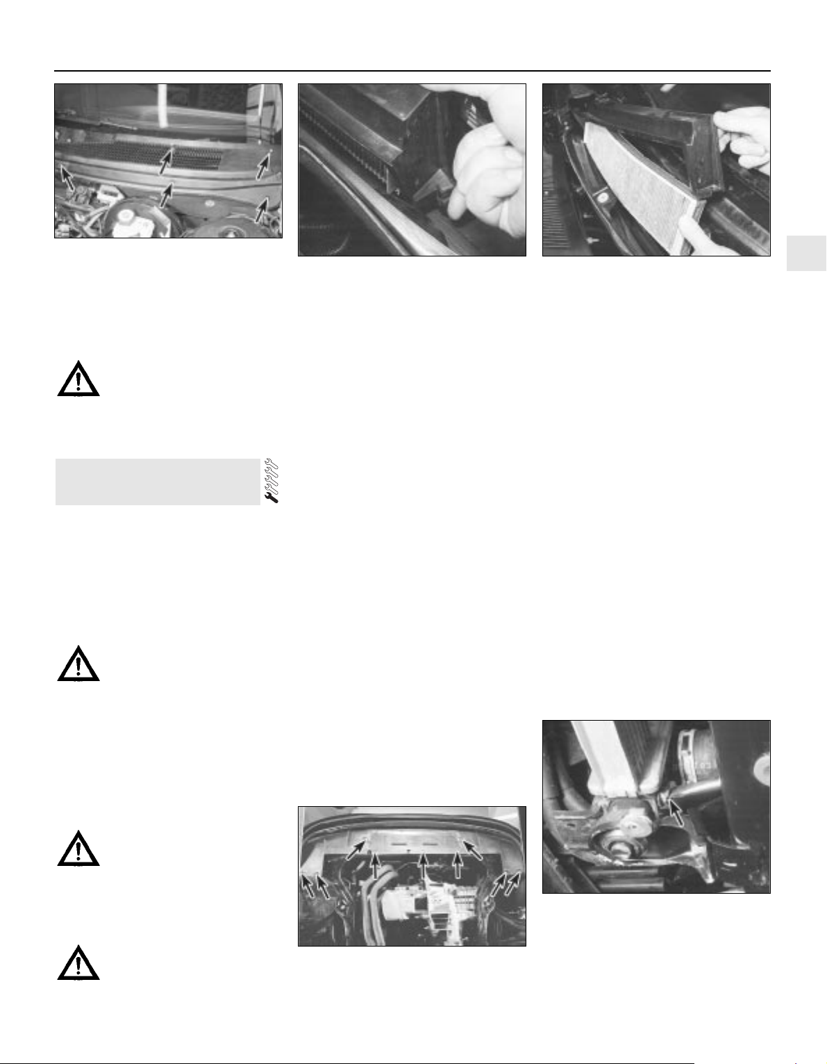
pleated-paper type filter, it cannot be washed
or re-oiled. If it cannot be cleaned
satisfactorily with compressed air, discard
and renew it.
Warning: Wear eye protection
when using compressed air!
8 Refitting is the reverse of the removal
procedure; ensure that the element and
housing are securely seated, so that unfiltered
air cannot enter the passenger compartment.
Note: If the antifreeze used is Ford’s own, or of
similar quality, the coolant need not be
renewed for the life of the vehicle. If the
vehicle’s history is unknown, if antifreeze of
lesser quality is known to be in the system, or
simply if you prefer to follow conventional
servicing intervals, the coolant should be
changed periodically (typically, every 2 years)
as described here. Refer also to the
information in Section 2 of this Chapter.
Warning: Do not allow antifreeze
to come in contact with your skin
or painted surfaces of the
vehicle. Flush contaminated areas
immediately with plenty of water. Don’t
store new coolant, or leave old coolant
lying around, where it’s accessible to
children or pets - they’re attracted by its
sweet smell. Ingestion of even a small
amount of coolant can be fatal! Wipe up
garage-floor and drip-pan spills
immediately. Keep antifreeze containers
covered, and repair cooling system leaks
as soon as they’re noticed.
Warning: Never remove the
expansion tank filler cap when
the engine is running, or has just
been switched off, as the cooling system
will be hot, and the consequent escaping
steam and scalding coolant could cause
serious injury.
Coolant draining
Warning: Wait until the engine is
cold before starting this
procedure.
1 To drain the system, first remove the
expansion tank filler cap (see Section 3).
2 If the additional working clearance is
required, raise the front of the vehicle and
support it securely on axle stands.
3 Remove the radiator undershield (eight or
nine screws), then place a large drain tray
underneath, and unscrew the radiator drain
plug; direct as much of the escaping coolant
as possible into the tray (see illustrations).
System flushing
4 With time, the cooling system may
gradually lose its efficiency, as the radiator
core becomes choked with rust, scale
deposits from the water, and other sediment
(refer also to the information at the start of
Section 2). To minimise this, as well as using
only good-quality antifreeze and clean soft
water, the system should be flushed as
follows whenever any part of it is disturbed,
and/or when the coolant is renewed.
5 With the coolant drained, refit the drain plug
and refill the system with fresh water. Refit the
expansion tank filler cap, start the engine and
warm it up to normal operating temperature,
then stop it and (after allowing it to cool down
completely) drain the system again. Repeat as
necessary until only clean water can be seen
to emerge, then refill finally with the specified
coolant mixture.
6 If only clean, soft water and good-quality
antifreeze (even if not to Ford’s specification)
has been used, and the coolant has been
renewed at the suggested intervals, the above
procedure will be sufficient to keep clean the
system for a considerable length of time. If,
however, the system has been neglected, a
more thorough operation will be required, as
follows.
7 First drain the coolant, then disconnect the
radiator top and bottom hoses. Insert a
garden hose into the top hose, and allow
water to circulate through the radiator until it
runs clean from the bottom outlet.
8 To flush the engine, insert the garden hose
into the thermostat water outlet, and allow
water to circulate until it runs clear from the
bottom hose. If, after a reasonable period, the
water still does not run clear, the radiator
should be flushed with a good proprietary
cleaning agent.
9 In severe cases of contamination, reverseflushing of the radiator may be necessary. To
do this, remove the radiator (Chapter 3), invert
it, and insert the garden hose into the bottom
outlet. Continue flushing until clear water runs
from the top hose outlet. A similar procedure
can be used to flush the heater matrix.
10 The use of chemical cleaners should be
necessary only as a last resort. Normally,
regular renewal of the coolant will prevent
excessive contamination of the system.
Coolant filling
11 With the cooling system drained and
flushed, ensure that all disturbed hose unions
28 Coolant renewal
1•21
1
28.3A Remove the screws (arrowed) and
withdraw the radiator undershield . . .
28.3B . . . to unscrew the radiator drain
plug (arrowed) and empty the cooling
system. Try to protect yourself from
coolant splashing into your eyes or onto
your skin, catching as much of it as
possible in the drain tray
27.3 Remove screws (arrowed) to release
cowl grille panel . . .
27.5A . . . release clips to lift out pollen
filter housing . . .
27.5B . . . then withdraw pollen filter
element
Every 20 000 miles
Page 36
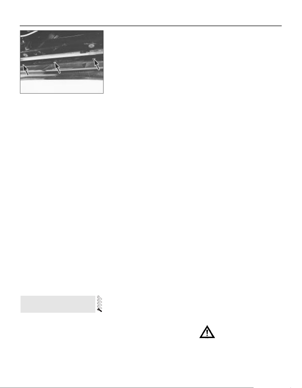
are correctly secured, and that the radiator
drain plug is securely tightened. Refit the
radiator undershield, noting that it is located
by three clips at its front edge; tighten the
retaining screws securely (see illustration). If
it was raised, lower the vehicle to the ground.
12 Prepare a sufficient quantity of the
specified coolant mixture (see below); allow
for a surplus, so as to have a reserve supply
for topping-up.
13 Slowly fill the system through the
expansion tank; since the tank is the highest
point in the system, all the air in the system
should be displaced into the tank by the rising
liquid. Slow pouring reduces the possibility of
air being trapped and forming air-locks.
14 Continue filling until the coolant level
reaches the expansion tank “MAX” level line,
then cover the filler opening to prevent
coolant splashing out.
15 Start the engine and run it at idle speed,
until it has warmed-up to normal operating
temperature and the radiator electric cooling
fan has cut in; watch the temperature gauge
to check for signs of overheating. If the level in
the expansion tank drops significantly, top-up
to the “MAX” level line, to minimise the
amount of air circulating in the system.
16 Stop the engine, allow it to cool down
completely (overnight, if possible), then
uncover the expansion tank filler opening and
top-up the tank to the “MAX” level line. Refit
the filler cap, tightening it securely, and wash
off any spilt coolant from the engine
compartment and bodywork.
17 After refilling, always check carefully all
components of the system (but especially any
unions disturbed during draining and flushing)
for signs of coolant leaks. Fresh antifreeze has
a searching action, which will rapidly expose
any weak points in the system.
18 Note: If, after draining and refilling the
system, symptoms of overheating are found
which did not occur previously, then the fault
is almost certainly due to trapped air at some
point in the system, causing an air-lock and
restricting the flow of coolant; usually, the air
is trapped because the system was refilled too
quickly. In some cases, air-locks can be
released by tapping or squeezing the various
hoses. If the problem persists, stop the engine
and allow it to cool down completely, before
unscrewing the expansion tank filler cap or
disconnecting hoses to bleed out the trapped
air.
Antifreeze mixture
19 If the antifreeze used is not to Ford’s
specification, it should always be renewed at
the suggested intervals. This is necessary not
only to maintain the antifreeze properties, but
also to prevent the corrosion which would
otherwise occur as the corrosion inhibitors
become progressively less effective. Always
use an ethylene glycol-based antifreeze which
is suitable for use in mixed-metal cooling
systems.
20 If the antifreeze used is to Ford’s
specification, the levels of protection it affords
are indicated in the Specifications Section of
this Chapter. To give the recommended
standard mixture ratio for this antifreeze, 40%
(by volume) of antifreeze must be mixed with
60% of clean, soft water; if you are using any
other type of antifreeze, follow its
manufacturer’s instructions to achieve the
correct ratio. It is best to make up slightly
more than the system’s specified capacity, so
that a supply is available for subsequent
topping-up.
21 Before adding antifreeze, the cooling
system should be completely drained,
preferably flushed, and all hoses checked for
condition and security. As noted earlier, fresh
antifreeze will rapidly find any weaknesses in
the system.
22 After filling with antifreeze, a label should
be attached to the expansion tank, stating the
type and concentration of antifreeze used,
and the date installed. Any subsequent
topping-up should be made with the same
type and concentration of antifreeze. If
topping-up using antifreeze to Ford’s
specification, note that a 50/50 mixture is
permissible, purely for convenience.
23 Do not use engine antifreeze in the
windscreen/tailgate washer system, as it will
damage the vehicle’s paintwork. A screen
wash additive should be added to the washer
system in its maker’s recommended
quantities.
General cooling system checks
24 The engine should be cold for the cooling
system checks, so perform the following
procedure before driving the vehicle, or after it
has been shut off for at least three hours.
25 Remove the expansion tank filler cap (see
Section 3), and clean it thoroughly inside and
out with a rag. Also clean the filler neck on the
expansion tank. The presence of rust or
corrosion in the filler neck indicates that the
coolant should be changed. The coolant
inside the expansion tank should be relatively
clean and transparent. If it is rust- coloured,
drain and flush the system, and refill with a
fresh coolant mixture.
26 Carefully check the radiator hoses and
heater hoses along their entire length; renew
any hose which is cracked, swollen or
deteriorated (see Section 12).
27 Inspect all other cooling system
components (joint faces, etc.) for leaks. A leak
in the cooling system will usually show up as
white- or rust-coloured deposits on the area
adjoining the leak. Where any problems of this
nature are found on system components,
renew the component or gasket with
reference to Chapter 3.
28 Clean the front of the radiator with a soft
brush to remove all insects, leaves, etc,
embedded in the radiator fins. Be careful not
to damage the radiator fins, or cut your fingers
on them.
1•22
28.11 Ensure radiator undershield is
located securely in three clips at front
edge (arrowed) when refitting
Every 30 000 miles
Every 30 000 miles or 3 years
1 The air filter element is located in the air
cleaner assembly on the left-hand side of the
engine compartment. Release the clips, and
lift the air cleaner cover (see illustrations). If
the additional working clearance is required,
unclip the cover from the air mass meter, and
withdraw it completely.
2 Lift out the element, and wipe out the
housing (see illustration). Check that no
foreign matter is visible, either in the air intake
or in the air mass meter.
3 If carrying out a routine service, the element
must be renewed regardless of its apparent
condition; note that the small foam filter in the
rear right-hand corner of the air cleaner
housing must be cleaned whenever the air
filter element is renewed (see Section 30).
4 If you are checking the element for any
other reason, inspect its lower surface; if it is
oily or very dirty, renew the element. If it is
only moderately dusty, it can be re-used by
blowing it clean from the upper to the lower
surface with compressed air. Because it is a
pleated-paper type filter, it cannot be washed
or re-oiled. If it cannot be cleaned
satisfactorily with compressed air, discard
and renew it.
Warning: Wear eye protection
when using compressed air!
Caution: Never drive the vehicle
with the air cleaner filter element
removed. Excessive engine wear could
result, and backfiring could even cause a
fire under the bonnet.
29 Air filter element renewal
Page 37
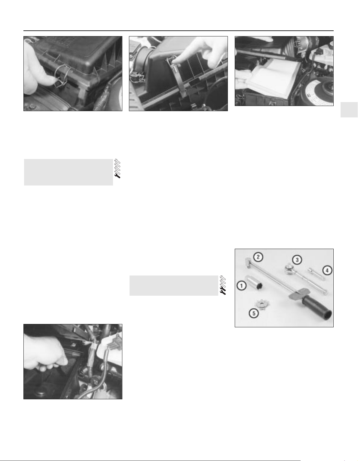
5 Refitting is the reverse of the removal
procedure. Ensure that the element and cover
are securely seated, so that unfiltered air
cannot enter the engine.
1 The Positive Crankcase Ventilation (PCV)
system components are located at the front of
the engine, underneath the exhaust manifold
and air intake resonator. Refer to Chapter 6
for further information.
2 Check that all components of the system
are securely fastened, correctly routed (with
no kinks or sharp bends to restrict flow) and in
sound condition; renew any worn or damaged
components.
3 If oil leakage is noted, disconnect the
various hoses and pipes, and check that all
are clear and unblocked. Remove the air
cleaner assembly cover, air mass meter and
resonator, then check that the hose from the
cylinder head cover to the air cleaner housing
is clear and undamaged. Disconnect the
rubber T-piece both from the union on the
inlet manifold left-hand end, and from the
metal crankcase breather pipe under the
ignition coil. Connect a spare, clean, length of
hose to the breather pipe. Suck on the end of
the hose, then blow through it - little or no
restriction to airflow should be felt in either
direction. A similar test can be applied to
check that the inlet manifold passages are
clear - air should be heard hissing out of the
plenum chamber mouth as you blow.
4 The PCV valve is designed to allow gases
to flow out of the crankcase only, so that a
depression is created in the crankcase under
most operating conditions, particularly at idle.
Therefore, if either the oil separator or the PCV
valve are thought to be blocked, they must be
renewed (see Chapter 6). In such a case,
however, there is nothing to be lost by
attempting to flush out the blockage using a
suitable solvent. The PCV valve should rattle
when shaken.
5 While the air filter element is removed (see
Section 29), wipe out the housing, and
withdraw the small foam filter from its location
in the rear right-hand corner of the housing
(see illustration). If the foam is badly clogged
with dirt or oil, it must be cleaned by soaking it
in a suitable solvent, and allowed to dry
before being refitted.
Spark plug check and renewal
1 It is vital for the correct running, full
performance and proper economy of the
engine that the spark plugs perform with
maximum efficiency. The most important
factor in ensuring this is that the plugs fitted
are appropriate for the engine. The suitable
type is given in the Specifications Section at
the beginning of this Chapter, on the Vehicle
Emissions Control Information (VECI) label
located on the underside of the bonnet (only
on models sold in some areas) or in the
vehicle’s Owner’s Handbook. If these sources
specify different plugs, purchase the spark
plug type specified on the VECI label (where
appropriate), as that information is provided
specifically for your engine. If this type is used
and the engine is in good condition, the spark
plugs should not need attention between
scheduled renewal intervals. Spark plug
cleaning is rarely necessary, and should not
be attempted unless specialised equipment is
available, as damage can easily be caused to
the firing ends.
2 Spark plug removal and refitting requires a
spark plug socket, with an extension which
can be turned by a ratchet handle or similar.
This socket is lined with a rubber sleeve, to
protect the porcelain insulator of the spark
plug, and to hold the plug while you insert it
into the spark plug hole. You will also need a
wire-type feeler gauge, to check and adjust
the spark plug electrode gap, and a torque
wrench to tighten the new plugs to the
specified torque (see illustration).
3 To remove the spark plugs, first open the
bonnet; the plugs are easily reached at the
top of the engine. Note how the spark plug
(HT) leads are routed and secured by clips
along the channel in the cylinder head cover.
31 Spark plug renewal
30 Positive Crankcase
Ventilation (PCV) system
check and filter cleaning
1•23
1
30.5 The Positive Crankcase Ventilation
(PCV) system filter in the air cleaner
assembly must be cleaned whenever the
air filter element is renewed
31.2 Tools required for changing spark
plugs
1 Spark plug socket - This will have special
padding inside, to protect the spark plug
porcelain insulator
2 Torque wrench - Although not essential,
use of this tool is the best way to ensure that
the plugs are tightened properly
3 Ratchet - Standard hand tool to fit the
plug socket
4 Extension - Depending on the other tools
available, you may need an extension to reach
the plugs
5 Spark plug gap gauge - This gauge for
checking the gap comes in a variety of styles.
Make sure the gap for your engine is included
29.1A Release the wire clips to detach the
cover from the air cleaner assembly . . .
29.1B . . . noting the long clip normally
hidden by the battery . . .
29.2 . . . lift the element out of the housing,
and wipe out its interior before fitting the
new element
Every 30 000 miles
Page 38
To prevent the possibility of mixing up spark
plug (HT) leads, it is a good idea to try to work
on one spark plug at a time.
4 If the marks on the original-equipment
spark plug (HT) leads cannot be seen, mark
the leads 1 to 4, to correspond to the cylinder
the lead serves (No 1 cylinder is at the timing
belt end of the engine). Pull the leads from the
plugs by gripping the rubber boot sealing the
cylinder head cover opening, not the lead,
otherwise the lead connection may be
fractured.
5 It is advisable to soak up any water in the
spark plug recesses with a rag, and to remove
any dirt from them using a clean brush,
vacuum cleaner or compressed air before
removing the plugs, to prevent any dirt or
water from dropping into the cylinders.
Warning: Wear eye protection
when using compressed air!
6 Unscrew the spark plugs, ensuring that the
socket is kept in alignment with each plug - if
the socket is forcibly moved to either side, the
porcelain top of the plug may be broken off. If
any undue difficulty is encountered when
unscrewing any of the spark plugs, carefully
1•24
Every 30 000 miles
Specifications
Engine
Direction of crankshaft rotation . . . . . . . . . . . . . . . . . . . . . . . . . . . . . . . . Clockwise (seen from right-hand side of vehicle)
Oil filter . . . . . . . . . . . . . . . . . . . . . . . . . . . . . . . . . . . . . . . . . . . . . . . . . . Champion C148
Cooling system
Coolant protection at 40% antifreeze/water mixture ratio:
Slush point . . . . . . . . . . . . . . . . . . . . . . . . . . . . . . . . . . . . . . . . . . . . . -25°C (-13°F)
Solidifying point . . . . . . . . . . . . . . . . . . . . . . . . . . . . . . . . . . . . . . . . . . -30°C (-22°F)
Coolant specific gravity at 40% antifreeze/water mixture ratio and
15°C/59°F - with no other additives in coolant . . . . . . . . . . . . . . . . . . . . 1.061
Fuel system
Idle speed - nominal . . . . . . . . . . . . . . . . . . . . . . . . . . . . . . . . . . . . . . . . 830 ± 50 rpm*
Air filter element . . . . . . . . . . . . . . . . . . . . . . . . . . . . . . . . . . . . . . . . . . . Champion U618
Fuel filter . . . . . . . . . . . . . . . . . . . . . . . . . . . . . . . . . . . . . . . . . . . . . . . . . Champion L218
* Note: Given for reference only - not adjustable.
Ignition system
Firing order . . . . . . . . . . . . . . . . . . . . . . . . . . . . . . . . . . . . . . . . . . . . . . . 1-3-4-2 (No 1 cylinder at timing belt end of engine)
Spark plugs:*
Type . . . . . . . . . . . . . . . . . . . . . . . . . . . . . . . . . . . . . . . . . . . . . . . . . . . Champion RE7YCC
Electrode gap . . . . . . . . . . . . . . . . . . . . . . . . . . . . . . . . . . . . . . . . . . . 1.0 mm
Spark plug (HT) leads:
Type . . . . . . . . . . . . . . . . . . . . . . . . . . . . . . . . . . . . . . . . . . . . . . . . . . . Champion type not available
Maximum resistance per lead . . . . . . . . . . . . . . . . . . . . . . . . . . . . . . . 30 000 ohms
* Information on spark plug types and electrode gaps is as recommended by Champion Spark Plug. Where alternative types are used, refer to
their manufacturer’s recommendations
Braking system
Note: No minimum lining thicknesses are given by Ford - the following is given as a general recommendation. If the pad wear warning light
comes on before the front brake pad linings reach the minimum thickness, the pads should nevertheless be renewed immediately.
Minimum front or rear brake pad lining thickness . . . . . . . . . . . . . . . . . 1.5 mm
Minimum rear brake shoe lining thickness . . . . . . . . . . . . . . . . . . . . . . . 1.0 mm
Suspension and steering
Tyre pressures (cold): Front Rear
Normally laden* . . . . . . . . . . . . . . . . . . . . . . . . . . . . . . . . . . . . . . . . . 2.1 bars (31 psi) 2.1 bars (31 psi)
Fully laden* . . . . . . . . . . . . . . . . . . . . . . . . . . . . . . . . . . . . . . . . . . . . . 2.4 bars (35 psi) 2.8 bars (41 psi)
Note: Normally laden means up to 3 persons. For sustained high speeds above 100 mph (160 km/h), increased pressures are necessary.
Consult the driver’s handbook supplied with the vehicle.
Wiper blades
Windscreen:
Driver’s side . . . . . . . . . . . . . . . . . . . . . . . . . . . . . . . . . . . . . . . . . . . . . Champion X 5303 (and SP 01 spoiler)
Passenger’s side . . . . . . . . . . . . . . . . . . . . . . . . . . . . . . . . . . . . . . . . . Champion X 5103
Tailgate:
Hatchback . . . . . . . . . . . . . . . . . . . . . . . . . . . . . . . . . . . . . . . . . . . . . . Champion X 5103
Estate . . . . . . . . . . . . . . . . . . . . . . . . . . . . . . . . . . . . . . . . . . . . . . . . . Champion type not available
Torque wrench settings Nm lbf ft
Auxiliary drivebelt cover fasteners . . . . . . . . . . . . . . . . . . . . . . . . . . . . . 5 to 10 4 to 7
Auxiliary drivebelt automatic tensioner Torx screws . . . . . . . . . . . . . . . . 23 17
Engine oil drain plug . . . . . . . . . . . . . . . . . . . . . . . . . . . . . . . . . . . . . . . . 25 18
Manual transmission filler/level plug . . . . . . . . . . . . . . . . . . . . . . . . . . . . 35 26
Radiator undershield screws . . . . . . . . . . . . . . . . . . . . . . . . . . . . . . . . . . 7 5
Spark plugs . . . . . . . . . . . . . . . . . . . . . . . . . . . . . . . . . . . . . . . . . . . . . . . 15 11
Page 39
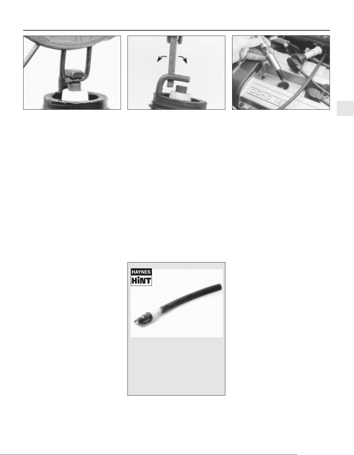
check the cylinder head threads and tapered
sealing surfaces for signs of wear, excessive
corrosion or damage; if any of these
conditions is found, seek the advice of a Ford
dealer as to the best method of repair.
7 As each plug is removed, examine it as
follows - this will give a good indication of the
condition of the engine. If the insulator nose of
the spark plug is clean and white, with no
deposits, this is indicative of a weak mixture.
8 If the tip and insulator nose are covered
with hard black-looking deposits, then this is
indicative that the mixture is too rich. Should
the plug be black and oily, then it is likely that
the engine is fairly worn, as well as the mixture
being too rich.
9 If the insulator nose is covered with light tan
to greyish-brown deposits, then the mixture is
correct, and it is likely that the engine is in
good condition.
10 If you are renewing the spark plugs,
purchase the new plugs, then check each of
them first for faults such as cracked insulators
or damaged threads. Note also that,
whenever the spark plugs are renewed as a
routine service operation, the spark plug (HT)
leads should be checked as described below.
11 The spark plug electrode gap is of
considerable importance as, if it is too large or
too small, the size of the spark and its
efficiency will be seriously impaired. The gap
should be set to the value given in the
Specifications Section of this Chapter. New
plugs will not necessarily be set to the correct
gap, so they should always be checked
before fitting.
12 Special spark plug electrode gap
adjusting tools are available from most motor
accessory shops (see illustration).
13 To set the electrode gap, measure the
gap with a feeler gauge, and then bend open,
or closed, the outer plug electrode until the
correct gap is achieved (see illustration). The
centre electrode should never be bent, as this
may crack the insulation and cause plug
failure, if nothing worse. If the outer electrode
is not exactly over the centre electrode, bend
it gently to align them.
14 Before fitting the spark plugs, check that
the threaded connector
sleeves at the top of the plugs are tight, and
that the plug exterior surfaces and threads are
clean. Brown staining on the porcelain,
immediately above the metal body, is quite
normal, and does not necessarily indicate a
leak between the body and insulator.
15 On installing the spark plugs, first check
that the cylinder head thread and sealing
surface are as clean as possible; use a clean
rag wrapped around a paintbrush to wipe
clean the sealing surface. Apply a smear of
copper-based grease or anti-seize compound
to the threads of each plug, and screw them
in by hand where possible. Take extra care to
enter the plug threads correctly, as the
cylinder head is of aluminium alloy - it’s often
difficult to insert spark plugs into their holes
without cross-threading them.
16 When each spark plug is started correctly
on its threads, screw it down until it just seats
lightly, then tighten it to the specified torque
wrench setting (see illustration). If a torque
wrench is not available - and this is one case
where the use of a torque wrench is strongly
recommended - tighten each spark plug
through no more than 1/16 of a turn. Do not
exceed the specified torque setting, and
NEVER overtighten these spark plugs - their
tapered seats mean they are almost
impossible to remove if abused.
17 Reconnect the spark plug (HT) leads in
their correct order, using a twisting motion on
the boot until it is firmly seated on the end of
the spark plug and on the cylinder head cover.
Spark plug (HT) lead check
18 The spark plug (HT) leads should be
checked whenever the plugs themselves are
renewed. Start by making a visual check of
the leads while the engine is running. In a
darkened garage (make sure there is
ventilation) start the engine and observe each
lead. Be careful not to come into contact with
any moving engine parts. If there is a break in
the lead, you will see arcing or a small spark
at the damaged area.
19 The spark plug (HT) leads should be
inspected one at a time, to prevent mixing up
the firing order, which is essential for proper
engine operation. Each original lead should be
numbered to identify its cylinder. If the
number is illegible, a piece of tape can be
marked with the correct number, and
wrapped around the lead (the leads should be
numbered 1 to 4, with No 1 lead nearest the
timing belt end of the engine). The lead can
then be disconnected.
20 Check inside the boot for corrosion, which
will look like a white crusty powder. Clean this
off as much as possible; if it is excessive, or if
cleaning leaves the metal connector too badly
corroded to be fit for further use, the lead
must be renewed. Push the lead and boot
back onto the end of the spark plug. The boot
should fit tightly onto the end of the plug - if it
doesn’t, remove the lead and use pliers
carefully to crimp the metal connector inside
the boot until the fit is snug.
21 Using a clean rag, wipe the entire length of
1•25
1
Every 30 000 miles
31.12 Spark plug manufacturers
recommend using a wire-type gauge when
checking the gap - if the wire does not
slide between the electrodes with a slight
drag, adjustment is required
31.13 To change the gap, bend the outer
electrode only, as indicated by the arrows,
and be very careful not to crack or chip the
porcelain insulator surrounding the centre
electrode
31.16 Spark plugs have tapered seats - do
not overtighten them on refitting, or you
will not be able to get them out again
without risking damage to the plugs and
cylinder head
To avoid the possibility of crossthreading a spark plug, fit a short piece
of rubber hose over the end of the
plug. The flexible hose acts as a
universal joint, to help align the plug
with the plug hole. Should the plug
begin to cross-thread, the hose will slip
on the spark plug, preventing thread
damage.
Page 40
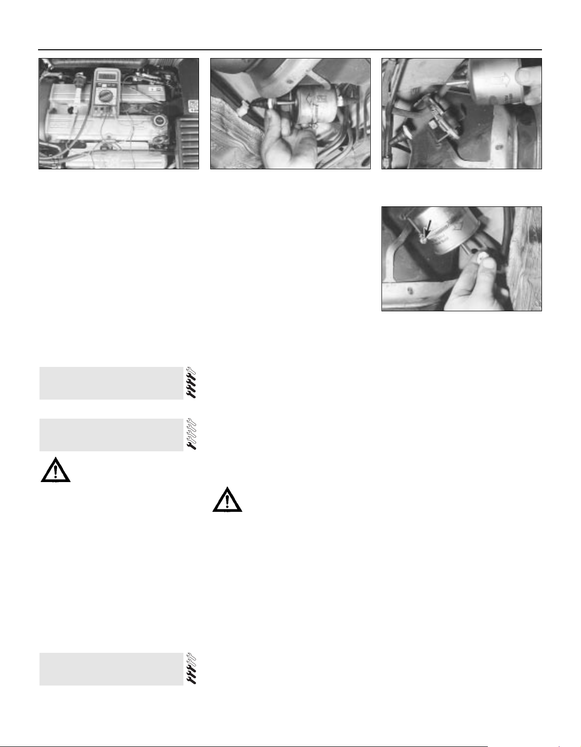
1•26
Every 60 000 miles
Every 60 000 miles
Refer to Chapter 2, Part A.
Warning: Petrol is extremely
flammable, so extra precautions
must be taken when working on
any part of the fuel system. Do not smoke,
or allow open flames or bare light bulbs,
near the work area. Also, do not work in a
garage if a gas appliance with a pilot light is
present. While performing any work on the
fuel system, wear safety glasses, and have
a suitable (Class B) fire extinguisher on
hand. If you spill any fuel on your skin, rinse
it off immediately with soap and water.
1 The fuel filter is located at the front righthand corner of the fuel tank, just forward of
the vehicle’s right-hand rear jacking point. The
filter performs a vital role in keeping dirt and
other foreign matter out of the fuel system,
and so must be renewed at regular intervals,
or whenever you have reason to suspect that
it may be clogged. It is always unpleasant
working under a vehicle - pressure-washing or
hosing clean the underbody in the filter’s
vicinity will make working conditions more
tolerable, and will reduce the risk of getting
dirt into the fuel system.
2 Relieve any residual pressure in the system
by removing the fuel pump fuse (No 14) and
starting the engine; allow the engine to idle until
it dies. Turn the engine over once or twice on
the starter, to ensure that all pressure is
released, then switch off the ignition.
Warning: This procedure will
merely relieve the pressure
necessary for the engine to run remember that fuel will still be present in
the system components, and take
precautions before disconnecting them.
3 Noting the comments made in Section 1 of
Chapter 5, disconnect the battery earth terminal.
4 Jack up the rear right-hand side of the
vehicle, and support it securely on an axle stand.
5 Using rag to soak up any spilt fuel, release
the fuel feed and outlet pipe unions from the
filter, by squeezing together the protruding
locking lugs on each union, and carefully
pulling the union off the filter stub (see
illustration). Where the unions are colourcoded, the feed and outlet pipes cannot be
confused; where both unions are the same
colour, note carefully which pipe is connected
to which filter stub, and ensure that they are
correctly reconnected on refitting.
6 Noting the arrows and/or other markings on
the filter showing the direction of fuel flow
(towards the engine), slacken the filter clamp
screw and withdraw the filter. Note that the
filter will still contain fuel; care should be
taken, to avoid spillage and to minimise the
risk of fire.
7 On installation, slide the filter into its clamp
so that the arrow marked on it faces the
correct way, then slide each pipe union on to
its (correct) respective filter stub, and press it
down until the locking lugs click into their
groove (see illustrations). Tighten the clamp
screw carefully, until the filter is just prevented
from moving; do not overtighten the clamp
screw, or the filter casing may be crushed.
8 Refit the fuel pump fuse and reconnect the
battery earth terminal, then switch the ignition
on and off five times, to pressurise the
system. Check for any sign of fuel leakage
around the filter unions before lowering the
vehicle to the ground and starting the engine.
33 Fuel filter renewal
32 Timing belt renewal
33.5 Squeeze together fuel filter pipe union
locking lugs, then pull pipes off filter stubs -
ensure pipes are correctly reconnected
33.7A When installing the new filter,
ensure the arrow showing direction of fuel
flow points towards the engine . . .
Every 3 years
The procedure is similar to that for the
bleeding of the hydraulic system as described
in Chapter 9, except that the brake fluid
reservoir should be emptied by syphoning,
and allowance should be made for the old
fluid to be removed from the circuit when
bleeding a section of the circuit.
34 Brake fluid renewal
31.22 Measure the resistance of the spark
plug leads - if any exceeds the specified
maximum value, renew all the leads
the lead to remove built-up dirt and grease.
Once the lead is clean, check for burns, cracks
and other damage. Do not bend the lead
sharply, because the conductor might break.
22 Disconnect the lead from the ignition coil
by pressing together the plastic retaining
catches and pulling the end fitting off the coil
terminal. Check for corrosion and for a tight
fit. If a meter with the correct measuring range
is available, measure the resistance of the
disconnected lead from its coil connector to
its spark plug connector (see illustration). If
the resistance recorded for any of the leads
exceeds the value specified, all the leads
should be renewed as a set. Refit the lead to
the coil, noting that each coil terminal is
marked with its respective cylinder number,
so that there is no risk of mixing up the leads
and upsetting the firing order.
23 Inspect the remaining plug leads, ensuring
that each is securely fastened both ends when
the check is complete. If any sign of arcing,
severe connector corrosion, burns, cracks or
other damage is noticed, obtain new spark
plug (HT) leads, renewing them as a set. If new
spark plug leads are to be fitted, remove and
refit them one at a time, to avoid mix-ups in
the firing order.
33.7B . . . secure pipe unions as described do not overtighten clamp screw (arrowed)
Page 41
Chapter 2 Part A:
In-car engine repair procedures
Auxiliary drivebelt check and renewal . . . . . . . . . . . . . See Chapter 1
Camshaft oil seals - renewal . . . . . . . . . . . . . . . . . . . . . . . . . . . . . . . 12
Camshafts and hydraulic tappets - removal, inspection
and refitting . . . . . . . . . . . . . . . . . . . . . . . . . . . . . . . . . . . . . . . . . . 13
Compression test - description and interpretation . . . . . . . . . . . . . . 3
Crankshaft oil seals - renewal . . . . . . . . . . . . . . . . . . . . . . . . . . . . . . 20
Crankshaft pulley - removal and refitting . . . . . . . . . . . . . . . . . . . . . 8
Cylinder head - removal and refitting . . . . . . . . . . . . . . . . . . . . . . . . 14
Cylinder head and valve components - cleaning and
inspection . . . . . . . . . . . . . . . . . . . . . . . . . . . . . . . . . . . See Chapter 2B
Cylinder head cover - removal and refitting . . . . . . . . . . . . . . . . . . . 5
Engine oil and filter change . . . . . . . . . . . . . . . . . . . . . See Chapter 1
Engine oil level check . . . . . . . . . . . . . . . . . . . . . . . . . . See Chapter 1
Engine overhaul - general information . . . . . . . . . . . . . See Chapter 2B
Engine/transmission - removal and refitting . . . . . . . . See Chapter 2B
Engine/transmission mountings - inspection and renewal . . . . . . . . 22
Exhaust manifold - removal, inspection and refitting . . . . . . . . . . . . 7
Flywheel/driveplate - removal, inspection and refitting . . . . . . . . . . 21
General information . . . . . . . . . . . . . . . . . . . . . . . . . . . . . . . . . . . . . . 1
Inlet manifold - removal and refitting . . . . . . . . . . . . . . . . . . . . . . . . 6
Oil cooler - removal and refitting . . . . . . . . . . . . . . . . . . . . . . . . . . . . 17
Oil level sensor - removal and refitting . . . . . . . . . . . . . . . . . . . . . . . 18
Oil pressure warning light switch - removal and refitting . . . . . . . . . 19
Oil pump - removal, inspection and refitting . . . . . . . . . . . . . . . . . . . 16
Repair operations possible with the engine in the vehicle . . . . . . . . 2
Spark plug renewal . . . . . . . . . . . . . . . . . . . . . . . . . . . See Chapter 1
Sump - removal and refitting . . . . . . . . . . . . . . . . . . . . . . . . . . . . . . . 15
Timing belt - removal, refitting and adjustment . . . . . . . . . . . . . . . . 10
Timing belt covers - removal and refitting . . . . . . . . . . . . . . . . . . . . . 9
Timing belt tensioner and toothed pulleys - removal,
inspection and refitting . . . . . . . . . . . . . . . . . . . . . . . . . . . . . . . . . 11
Top Dead Centre (TDC) for No 1 piston - locating . . . . . . . . . . . . . . 4
Water pump - removal and refitting . . . . . . . . . . . . . . . See Chapter 3
General
Engine type . . . . . . . . . . . . . . . . . . . . . . . . . . . . . . . . . . . . . . . . . . . . . . . Four-cylinder, in-line, double overhead camshafts
Engine code:
1.6 litre models . . . . . . . . . . . . . . . . . . . . . . . . . . . . . . . . . . . . . . . . . . LIF
1.8 litre models . . . . . . . . . . . . . . . . . . . . . . . . . . . . . . . . . . . . . . . . . . RKA
2.0 litre models . . . . . . . . . . . . . . . . . . . . . . . . . . . . . . . . . . . . . . . . . . NGA
Capacity:
1.6 litre models . . . . . . . . . . . . . . . . . . . . . . . . . . . . . . . . . . . . . . . . . . 1597 cc
1.8 litre models . . . . . . . . . . . . . . . . . . . . . . . . . . . . . . . . . . . . . . . . . . 1796 cc
2.0 litre models . . . . . . . . . . . . . . . . . . . . . . . . . . . . . . . . . . . . . . . . . . 1988 cc
Bore:
1.6 litre models . . . . . . . . . . . . . . . . . . . . . . . . . . . . . . . . . . . . . . . . . . 76.0 mm
1.8 litre models . . . . . . . . . . . . . . . . . . . . . . . . . . . . . . . . . . . . . . . . . . 80.6 mm
2.0 litre models . . . . . . . . . . . . . . . . . . . . . . . . . . . . . . . . . . . . . . . . . . 84.8 mm
Stroke - all models . . . . . . . . . . . . . . . . . . . . . . . . . . . . . . . . . . . . . . . . . 88.0 mm
Compression ratio:
1.6 litre models . . . . . . . . . . . . . . . . . . . . . . . . . . . . . . . . . . . . . . . . . . 10.3:1
1.8 and 2.0 litre models . . . . . . . . . . . . . . . . . . . . . . . . . . . . . . . . . . . . 10.0:1
Compression pressure - at starter motor speed, engine fully warmed-up . Not available
Firing order . . . . . . . . . . . . . . . . . . . . . . . . . . . . . . . . . . . . . . . . . . . . . . . 1-3-4-2 (No 1 cylinder at timing belt end)
Direction of crankshaft rotation . . . . . . . . . . . . . . . . . . . . . . . . . . . . . . . . Clockwise (seen from right-hand side of vehicle)
Cylinder head
Hydraulic tappet bore inside diameter . . . . . . . . . . . . . . . . . . . . . . . . . . 28.395 to 28.425 mm
Camshafts and hydraulic tappets
Camshaft bearing journal diameter . . . . . . . . . . . . . . . . . . . . . . . . . . . . . 25.960 to 25.980 mm
Camshaft bearing journal-to-cylinder head running clearance . . . . . . . . 0.020 to 0.070 mm
Camshaft endfloat . . . . . . . . . . . . . . . . . . . . . . . . . . . . . . . . . . . . . . . . . . 0.080 to 0.220 mm
Hydraulic tappet diameter . . . . . . . . . . . . . . . . . . . . . . . . . . . . . . . . . . . . 28.400 mm
2A•1
Easy, suitable for
novice with little
experience
Fairly easy, suitable
for beginner with
some experience
Fairly difficult, suitable
for competent DIY
mechanic
Difficult, suitable for
experienced DIY
mechanic
Very difficult,
suitable for expert DIY
or professional
Degrees of difficulty
Specifications
Contents
2A
Page 42

Lubrication
Engine oil type/specification . . . . . . . . . . . . . . . . . . . . . . . . . . . . . . . . . . See Chapter 1
Engine oil capacity . . . . . . . . . . . . . . . . . . . . . . . . . . . . . . . . . . . . . . . . . See Chapter 1
Oil pressure . . . . . . . . . . . . . . . . . . . . . . . . . . . . . . . . . . . . . . . . . . . . . . . No information available at time of writing
Oil pump clearances . . . . . . . . . . . . . . . . . . . . . . . . . . . . . . . . . . . . . . . . No information available at time of writing
Torque wrench settings Nm lbf ft
Cylinder head cover bolts:
Stage 1 . . . . . . . . . . . . . . . . . . . . . . . . . . . . . . . . . . . . . . . . . . . . . . . . 2 1.5
Stage 2 . . . . . . . . . . . . . . . . . . . . . . . . . . . . . . . . . . . . . . . . . . . . . . . . 7 5
Camshaft toothed pulley bolts . . . . . . . . . . . . . . . . . . . . . . . . . . . . . . . . 68 50
Camshaft bearing cap bolts:
Stage 1 . . . . . . . . . . . . . . . . . . . . . . . . . . . . . . . . . . . . . . . . . . . . . . . . 10 7
Stage 2 . . . . . . . . . . . . . . . . . . . . . . . . . . . . . . . . . . . . . . . . . . . . . . . . 19 14
Cylinder head bolts:
Stage 1 . . . . . . . . . . . . . . . . . . . . . . . . . . . . . . . . . . . . . . . . . . . . . . . . 25 18
Stage 2 . . . . . . . . . . . . . . . . . . . . . . . . . . . . . . . . . . . . . . . . . . . . . . . . 45 33
Stage 3 . . . . . . . . . . . . . . . . . . . . . . . . . . . . . . . . . . . . . . . . . . . . . . . . Angle-tighten a further 105°
Timing belt cover fasteners:
Upper-to-middle (outer) cover bolts . . . . . . . . . . . . . . . . . . . . . . . . . . 4 3
Cover-to-cylinder head or block bolts . . . . . . . . . . . . . . . . . . . . . . . . 7 5
Cover studs-to-cylinder head or block . . . . . . . . . . . . . . . . . . . . . . . . 9 to 11 6.5 to 8
Timing belt tensioner bolt . . . . . . . . . . . . . . . . . . . . . . . . . . . . . . . . . . . . 38 28
Timing belt tensioner backplate locating peg . . . . . . . . . . . . . . . . . . . . . 8 to 11 6 to 8
Timing belt tensioner spring retaining pin . . . . . . . . . . . . . . . . . . . . . . . . 10 7
Timing belt guide pulley bolts . . . . . . . . . . . . . . . . . . . . . . . . . . . . . . . . . 35 to 40 26 to 30
Water pump pulley bolts . . . . . . . . . . . . . . . . . . . . . . . . . . . . . . . . . . . . . 10 7
Water pump bolts . . . . . . . . . . . . . . . . . . . . . . . . . . . . . . . . . . . . . . . . . . See Chapter 3
Auxiliary drivebelt idler pulley . . . . . . . . . . . . . . . . . . . . . . . . . . . . . . . . . 48 35
Inlet manifold nuts and bolts . . . . . . . . . . . . . . . . . . . . . . . . . . . . . . . . . . 18 13
Alternator mounting bracket-to-cylinder block bolts . . . . . . . . . . . . . . . 47 35
Cylinder head support plates:
Front plate Torx screws - to power steering pump/air conditioning
compressor mounting bracket and cylinder head . . . . . . . . . . . . . . . 47 35
Rear plate/engine lifting eye - to alternator mounting bracket
and cylinder head bolts . . . . . . . . . . . . . . . . . . . . . . . . . . . . . . . . . . . . 47 35
Front engine lifting eye bolt . . . . . . . . . . . . . . . . . . . . . . . . . . . . . . . . . . . 16 12
Inlet and exhaust manifold studs-to-cylinder head . . . . . . . . . . . . . . . . 10 maximum 7 maximum
Exhaust manifold heat shield bolts:
Shield-to-cylinder head . . . . . . . . . . . . . . . . . . . . . . . . . . . . . . . . . . . . 7 5
Shield/dipstick tube . . . . . . . . . . . . . . . . . . . . . . . . . . . . . . . . . . . . . . . 10 7
Shield/coolant pipe-to-manifold . . . . . . . . . . . . . . . . . . . . . . . . . . . . . 23 17
Exhaust manifold nuts . . . . . . . . . . . . . . . . . . . . . . . . . . . . . . . . . . . . . . . 16 12
Air conditioning refrigerant pipe-to-exhaust manifold bolts . . . . . . . . . . 10 7
Crankshaft pulley bolt . . . . . . . . . . . . . . . . . . . . . . . . . . . . . . . . . . . . . . . 108 to 115 80 to 85
Oil pump-to-cylinder block bolts . . . . . . . . . . . . . . . . . . . . . . . . . . . . . . 10 7
Oil pick-up pipe-to-pump screws . . . . . . . . . . . . . . . . . . . . . . . . . . . . . . 10 7
Oil baffle/pump pick-up pipe nuts . . . . . . . . . . . . . . . . . . . . . . . . . . . . . 19 14
Oil filter adaptor-to-pump . . . . . . . . . . . . . . . . . . . . . . . . . . . . . . . . . . . . 18 to 25 13 to 18
Oil pressure warning light switch . . . . . . . . . . . . . . . . . . . . . . . . . . . . . . 27 20
Oil level sensor . . . . . . . . . . . . . . . . . . . . . . . . . . . . . . . . . . . . . . . . . . . . 27 20
Sump bolts . . . . . . . . . . . . . . . . . . . . . . . . . . . . . . . . . . . . . . . . . . . . . . . 21 to 22 15 to 16
Coolant pipe-to-sump bolt . . . . . . . . . . . . . . . . . . . . . . . . . . . . . . . . . . . 10 7
Flywheel/driveplate bolts . . . . . . . . . . . . . . . . . . . . . . . . . . . . . . . . . . . . 110 to 112 81 to 83
Crankshaft left-hand oil seal carrier bolts . . . . . . . . . . . . . . . . . . . . . . . . 22 16
Transmission-to-engine bolts . . . . . . . . . . . . . . . . . . . . . . . . . . . . . . . . . 40 30
Engine/transmission front mounting:
Mounting bracket-to-transmission . . . . . . . . . . . . . . . . . . . . . . . . . . . Not available
Mounting-to-subframe bolts/nuts - stage 1 . . . . . . . . . . . . . . . . . . . . 10 7
Mounting-to-subframe bolts/nuts - stage 2 . . . . . . . . . . . . . . . . . . . . 48 35
Mounting centre bolt . . . . . . . . . . . . . . . . . . . . . . . . . . . . . . . . . . . . . . 120 89
Engine/manual transmission rear mounting:
Mounting bracket-to-transmission 12 mm fasteners . . . . . . . . . . . . . 78 to 84 58 to 62
Mounting bracket-to-transmission 10 mm fasteners . . . . . . . . . . . . . 48 35
Mounting-to-subframe bolts and nut - stage 1 . . . . . . . . . . . . . . . . . . 10 7
Mounting-to-subframe bolts and nut - stage 2 . . . . . . . . . . . . . . . . . . 48 35
Mounting centre bolt . . . . . . . . . . . . . . . . . . . . . . . . . . . . . . . . . . . . . . 120 89
2A•2 In-car engine repair procedures
Page 43
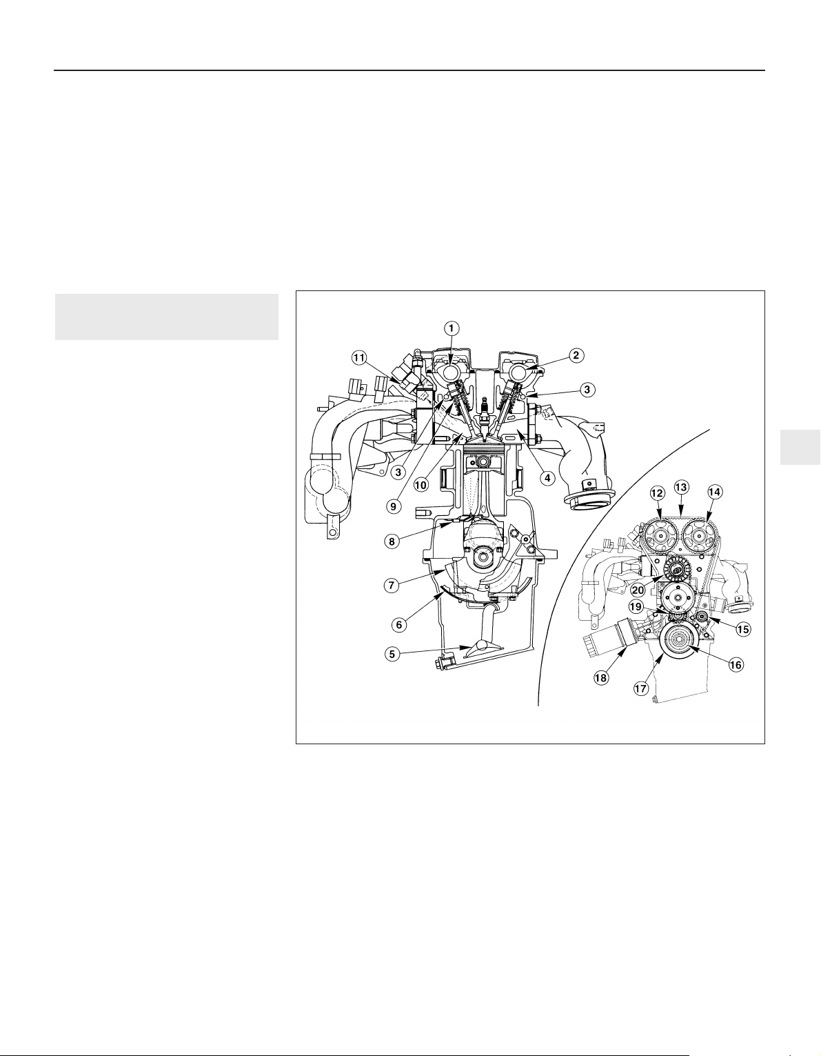
Torque wrench settings (continued) Nm lbf ft
Engine/automatic transmission rear mounting:
Mounting bracket-to-transmission . . . . . . . . . . . . . . . . . . . . . . . . . . . 48 to 49 35 to 36
Mounting-to-subframe bolts - stage 1 . . . . . . . . . . . . . . . . . . . . . . . . 10 7
Mounting-to-subframe bolts - stage 2 . . . . . . . . . . . . . . . . . . . . . . . . 48 35
Mounting centre bolt . . . . . . . . . . . . . . . . . . . . . . . . . . . . . . . . . . . . . . 120 89
Engine/transmission left-hand mounting:
Bracket-to-transmission nuts . . . . . . . . . . . . . . . . . . . . . . . . . . . . . . . 83 61
Mounting centre bolt . . . . . . . . . . . . . . . . . . . . . . . . . . . . . . . . . . . . . . Not available
Mounting-to-body bolts . . . . . . . . . . . . . . . . . . . . . . . . . . . . . . . . . . . Not available
Engine/transmission right-hand mounting:
Bracket-to-engine and mounting nuts . . . . . . . . . . . . . . . . . . . . . . . . 83 to 90 61 to 66
Mounting-to-body bolts . . . . . . . . . . . . . . . . . . . . . . . . . . . . . . . . . . . 84 62
Note: Refer to Part B of this Chapter for remaining torque wrench settings.
In-car engine repair procedures 2A•3
2A
How to use this Chapter
This Part of Chapter 2 is devoted to repair
procedures possible while the engine is still
installed in the vehicle, and includes only the
Specifications relevant to those procedures.
Since these procedures are based on the
assumption that the engine is installed in the
vehicle, if the engine has been removed from
the vehicle and mounted on a stand, some of
the preliminary dismantling steps outlined will
not apply.
Information concerning engine/transmission
removal and refitting, and engine overhaul, can
be found in Part B of this Chapter, which also
includes the Specifications relevant to those
procedures.
General description - engine
The engine, also known by Ford’s internal
code name “Zetec” (formerly “Zeta”), is of
four-cylinder, in-line type, mounted
transversely at the front of the vehicle, with
the (clutch and) transmission on its left-hand
end (see illustrations).
Apart from the plastic timing belt covers and
the cast-iron cylinder block/crankcase, all
major engine castings are of aluminium alloy.
The crankshaft runs in five main bearings,
the centre main bearing’s upper half
incorporating thrustwashers to control
crankshaft endfloat. The connecting rods
rotate on horizontally-split bearing shells at
their big-ends. The pistons are attached to the
connecting rods by gudgeon pins which are an
interference fit in the connecting rod small-end
eyes. The aluminium alloy pistons are fitted
with three piston rings: two compression rings
and an oil control ring. After manufacture, the
cylinder bores and piston skirts are measured
and classified into three grades, which must be
carefully matched together, to ensure the
correct piston/cylinder clearance; no oversizes
are available to permit reboring.
The inlet and exhaust valves are each
closed by coil springs; they operate in guides
which are shrink-fitted into the cylinder head,
as are the valve seat inserts.
Both camshafts are driven by the same
toothed timing belt, each operating eight
valves via self-adjusting hydraulic tappets,
thus eliminating the need for routine checking
and adjustment of the valve clearances. Each
camshaft rotates in five bearings that are line-
bored directly in the cylinder head and the
(bolted-on) bearing caps; this means that the
bearing caps are not available separately
from the cylinder head, and must not be
interchanged with caps from another engine.
The water pump is bolted to the right-hand
1 General information
1.3A Longitudinal cross-section through engine - inset showing timing belt details
1 Inlet camshaft
2 Exhaust camshaft
3 Oil galleries
4 Exhaust port
5 Oil strainer and pick-up pipe
6 Oil baffle
7 Crankshaft
8 Piston-cooling oil jet (where
fitted)
9 Inlet valve
10 Inlet port
11 Fuel injector
12 Inlet camshaft toothed
pulley
13 Timing belt
14 Exhaust camshaft toothed
pulley
15 Timing belt (front) guide
pulley
16 Crankshaft toothed pulley
- behind
17 Crankshaft pulley
18 Oil cooler (where fitted)
19 Timing belt (rear) guide
pulley
20 Timing belt tensioner
Page 44
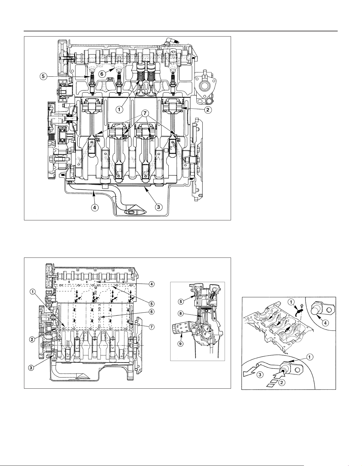
end of the cylinder block, inboard of the
timing belt, and is driven with the power
steering pump and alternator by a flat
“polyvee”-type auxiliary drivebelt from the
crankshaft pulley.
When working on this engine, note that
Torx-type (both male and female heads) and
hexagon socket (Allen head) fasteners are
widely used; a good selection of bits, with the
necessary adaptors, will be required, so that
these can be unscrewed without damage
and, on reassembly, tightened to the torque
wrench settings specified.
General description - lubrication
system
Lubrication is by means of an eccentricrotor trochoidal pump, which is mounted on
the crankshaft right-hand end, and draws oil
through a strainer located in the sump. The
pump forces oil through an externallymounted full-flow cartridge-type filter - on
some versions of the engine, an oil cooler is
fitted to the oil filter mounting, so that clean
oil entering the engine’s galleries is cooled by
the main engine cooling system. From the
filter, the oil is pumped into a main gallery in
the cylinder block/crankcase, from where it is
distributed to the crankshaft (main bearings)
and cylinder head (see illustration).
The big-end bearings are supplied with oil
via internal drillings in the crankshaft. On
some versions of the engine, each piston
crown is cooled by a spray of oil directed at
its underside by a jet. These jets are fed by
passages off the crankshaft oil supply
galleries, with spring-loaded valves to ensure
that the jets open only when there is sufficient
pressure to guarantee a good oil supply to
the rest of the engine components; where the
jets are not fitted, separate blanking plugs are
provided, so that the passages are sealed,
but can be cleaned at overhaul (see
illustration).
2A•4 In-car engine repair procedures
1.3B Lateral cross-section through engine
1 Exhaust valve
2 Piston
3 Oil baffle
4 Oil strainer and pick-up
pipe
5 Spark plug
6 Fuel injector
7 Piston-cooling oil jets
(where fitted)
1.10 Engine lubrication system - inset showing longitudinal cross-section
1 Main oil gallery
2 From oil filter
3 Oil pump
4 Cylinder head oil-retaining valve
5 Cylinder head oil gallery
6 Cylinder head oil supply
7 Oil return
8 Piston-cooling oil spray (where fitted)
9 Oil filter - oil cooler not shown here
1.11 Piston-cooling oil jet details
1 Oil jets (when fitted)
2 Oil flow - only when valve opens at set
pressure
3 Oil spray
4 Blanking plug (when fitted)
Page 45

The cylinder head is provided with two oil
galleries, one on the inlet side and one on the
exhaust, to ensure constant oil supply to the
camshaft bearings and hydraulic tappets. A
retaining valve (inserted into the cylinder
head’s top surface, in the middle, on the inlet
side) prevents these galleries from being
drained when the engine is switched off. The
valve incorporates a ventilation hole in its
upper end, to allow air bubbles to escape
from the system when the engine is restarted.
While the crankshaft and camshaft
bearings and the hydraulic tappets receive a
pressurised supply, the camshaft lobes and
valves are lubricated by splash, as are all
other engine components.
Valve clearances - general
It is necessary for a clearance to exist
between the tip of each valve stem and the
valve operating mechanism, to allow for the
expansion of the various components as the
engine reaches normal operating
temperature.
On most older engine designs, this meant
that the valve clearances (also known as
“tappet” clearances) had to be checked and
adjusted regularly. If the clearances were
allowed to be too slack, the engine would be
very noisy, its power output would suffer, and
its fuel consumption would increase. If the
clearances were allowed to be too tight, the
engine’s power output would be reduced,
and the valves and their seats could be
severely damaged.
The engines covered in this manual,
however, employ hydraulic tappets which use
the lubricating system’s oil pressure
automatically to take up the clearance
between each camshaft lobe and its
respective valve stem. Therefore, there is no
need for regular checking and adjustment of
the valve clearances, but it is essential that
only good-quality oil of the recommended
viscosity and specification is used in the
engine, and that this oil is always changed at
the recommended intervals. If this advice is
not followed, the oilways and tappets may
become clogged with particles of dirt, or
deposits of burnt (inferior) engine oil, so that
the system cannot work properly; ultimately,
one or more of the tappets may fail, and
expensive repairs may be required.
On starting the engine from cold, there will
be a slight delay while full oil pressure builds
up in all parts of the engine, especially in the
tappets; the valve components, therefore,
may well “rattle” for about 10 seconds or so,
and then quieten. This is a normal state of
affairs, and is nothing to worry about,
provided that all tappets quieten quickly and
stay quiet.
After the vehicle has been standing for
several days, the valve components may
“rattle” for longer than usual, as nearly all the
oil will have drained away from the engine’s
top end components and bearing surfaces.
While this is only to be expected, care must
be taken not to damage the engine under
these circumstances - avoid high speed
running until all the tappets are refilled with oil
and operating normally. With the vehicle
stationary, hold the engine at no more than a
fast idle speed (maximum 2000 to 2500 rpm)
for 10 to 15 seconds, or until the noise
ceases. Do not run the engine at more than
3000 rpm until the tappets are fully recharged
with oil and the noise has ceased.
If the valve components are thought to be
noisy, or if a light rattle persists from the top
end after the engine has warmed up to
normal operating temperature, take the
vehicle to a Ford dealer for expert advice.
Depending on the mileage covered and the
usage to which each vehicle has been put,
some vehicles may be noisier than others;
only a good mechanic experienced in these
engines can tell if the noise level is typical for
the vehicle’s mileage, or if a genuine fault
exists. If any tappet’s operation is faulty, it
must be renewed (Section 13).
The following major repair operations can
be accomplished without removing the
engine from the vehicle. However, owners
should note that any operation involving the
removal of the sump requires careful
forethought, depending on the level of skill
and the tools and facilities available; refer to
the relevant text for details.
(a) Compression pressure - testing.
(b) Cylinder head cover - removal and
refitting.
(c) Timing belt covers - removal and refitting.
(d) Timing belt - renewal.
(e) Timing belt tensioner and toothed pulleys
- removal and refitting.
(f) Camshaft oil seals - renewal.
(g) Camshafts and hydraulic tappets -
removal and refitting.
(h) Cylinder head - removal, overhaul and
refitting.
(i) Cylinder head and pistons -
decarbonising.
(j) Sump - removal and refitting.
(k) Crankshaft oil seals - renewal.
(l) Oil pump - removal and refitting.
(m) Piston/connecting rod assemblies -
removal and refitting (but see note below).
(n) Flywheel/driveplate - removal and
refitting.
(o) Engine/transmission mountings - removal
and refitting.
Clean the engine compartment and the
exterior of the engine with some type of
degreaser before any work is done. It will
make the job easier, and will help to keep dirt
out of the internal areas of the engine.
Depending on the components involved, it
may be helpful to remove the bonnet, to
improve access to the engine as repairs are
performed (refer to Chapter 11 if necessary).
Cover the wings to prevent damage to the
paint; special covers are available, but an old
bedspread or blanket will also work.
If vacuum, exhaust, oil or coolant leaks
develop, indicating a need for component/
gasket or seal replacement, the repairs can
generally be made with the engine in the
vehicle. The intake and exhaust manifold
gaskets, sump gasket, crankshaft oil seals
and cylinder head gasket are all accessible
with the engine in place.
Exterior components such as the intake
and exhaust manifolds, the sump, the oil
pump, the water pump, the starter motor, the
alternator and the fuel system components
can be removed for repair with the engine in
place.
Since the cylinder head can be removed
without lifting out the engine, camshaft and
valve component servicing can also be
accomplished with the engine in the vehicle,
as can renewal of the timing belt and toothed
pulleys.
In extreme cases caused by a lack of
necessary equipment, repair or renewal of
piston rings, pistons, connecting rods and
big-end bearings is possible with the engine
in the vehicle. However, this practice is not
recommended, because of the cleaning and
preparation work that must be done to the
components involved, and because of the
amount of preliminary dismantling work
required - these operations are therefore
covered in Part B of this Chapter.
1 When engine performance is down, or if
misfiring occurs which cannot be attributed to
the ignition or fuel systems, a compression
test can provide diagnostic clues as to the
engine’s condition. If the test is performed
regularly, it can give warning of trouble before
any other symptoms become apparent.
2 The engine must be fully warmed-up to
normal operating temperature, the oil level
must be correct, the battery must be fully
charged, and the spark plugs must be
removed. The aid of an assistant will be
required also.
3 Disable the ignition system by unplugging
the ignition coil’s electrical connector, and
remove fuse 14 to disconnect the fuel pump.
4 Fit a compression tester to the No 1
cylinder spark plug hole - the type of tester
which screws into the plug thread is to be
preferred.
5 Have the assistant hold the throttle wide
open and crank the engine on the starter
motor; after one or two revolutions, the
compression pressure should build up to a
maximum figure, and then stabilise. Record
the highest reading obtained.
6 Repeat the test on the remaining cylinders,
recording the pressure developed in each.
7 At the time of writing, no compression
3 Compression test -
description and interpretation
2 Repair operations possible with
the engine in the vehicle
In-car engine repair procedures 2A•5
2A
Page 46
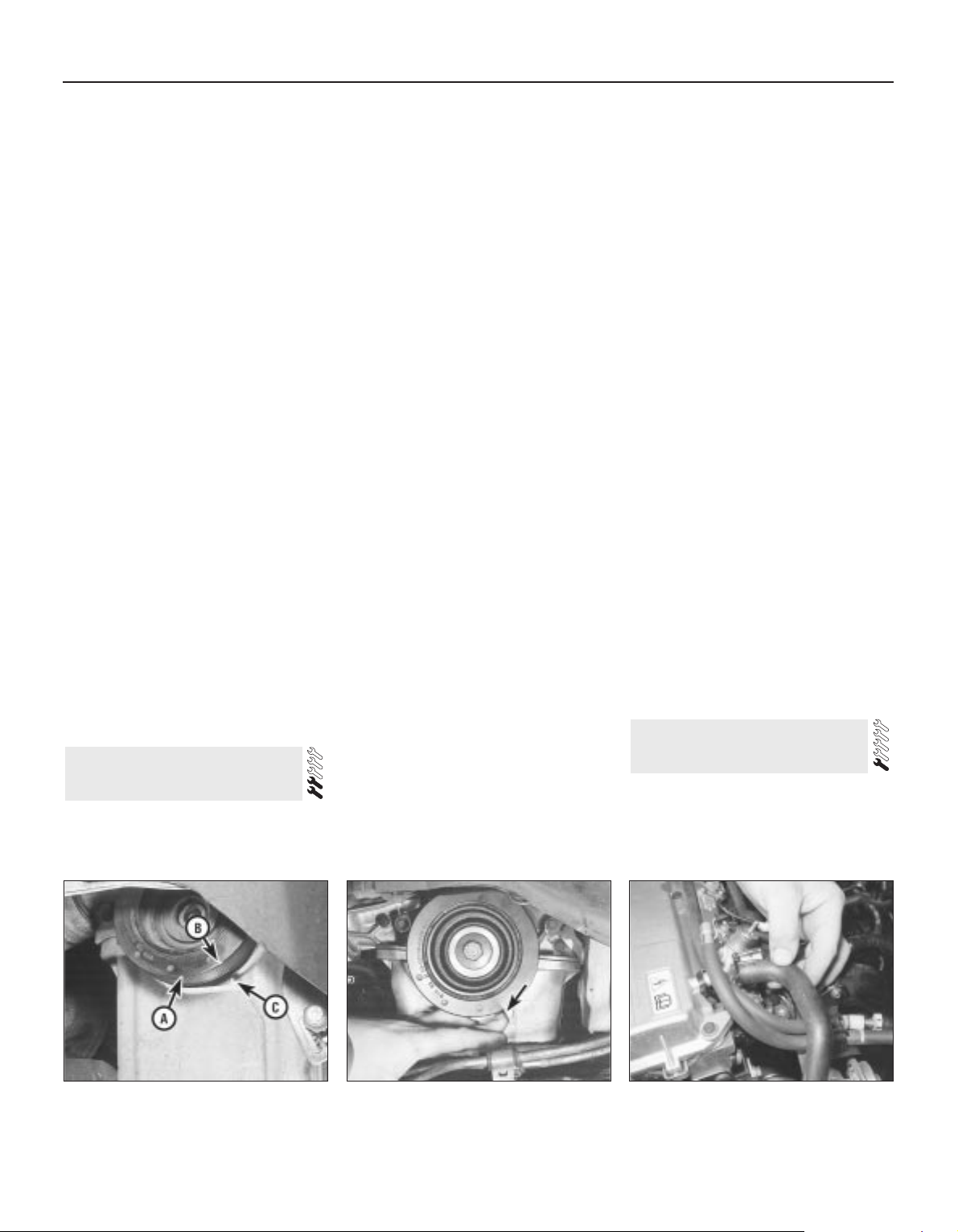
specifications were available from Ford, but a
typical reading would be in excess of 12 bars.
All cylinders should produce very similar
pressures; any difference greater than 10%
indicates the existence of a fault. Note that the
compression should build up quickly in a
healthy engine; low compression on the first
stroke, followed by gradually-increasing
pressure on successive strokes, indicates worn
piston rings. A low compression reading on the
first stroke, which does not build up during
successive strokes, indicates leaking valves or a
blown head gasket (a cracked head could also
be the cause). Deposits on the undersides of the
valve heads can also cause low compression.
8 If the pressure in any cylinder is
considerably lower than the others, introduce
a teaspoonful of clean oil into that cylinder
through its spark plug hole, and repeat the
test.
9 If the addition of oil temporarily improves
the compression pressure, this indicates that
bore or piston wear is responsible for the
pressure loss. No improvement suggests that
leaking or burnt valves, or a blown head
gasket, may be to blame.
10 A low reading from two adjacent cylinders
is almost certainly due to the head gasket
having blown between them; the presence of
coolant in the engine oil will confirm this.
11 If one cylinder is about 20 percent lower
than the others and the engine has a slightly
rough idle, a worn camshaft lobe or faulty
hydraulic tappet could be the cause.
12 If the compression is unusually high, the
combustion chambers are probably coated
with carbon deposits. If this is the case, the
cylinder head should be removed and
decarbonised.
13 On completion of the test, refit the spark
plugs, then reconnect the ignition system and
fuel pump.
General
1 Top Dead Centre (TDC) is the highest point
in its travel up-and-down its cylinder bore
that each piston reaches as the crankshaft
rotates. While each piston reaches TDC both
at the top of the compression stroke and
again at the top of the exhaust stroke, for the
purpose of timing the engine, TDC refers to
the piston position (usually No 1 piston) at the
top of its compression stroke.
2 It is useful for several servicing procedures
to be able to position the engine at TDC.
3 No 1 piston and cylinder are at the righthand (timing belt) end of the engine (rightand left-hand are always quoted as seen from
the driver’s seat). Note that the crankshaft
rotates clockwise when viewed from the
right-hand side of the vehicle.
Locating TDC
4 Remove all the spark plugs (Chapter 1).
5 Disconnect both battery leads - see
Chapter 5, Section 1 - unless the starter
motor is to be used to turn the engine.
6 Apply the handbrake and ensure that the
transmission is in neutral, then jack up the
front right-hand side of the vehicle and
support on an axle stand. Remove the
roadwheel.
7 Remove the auxiliary drivebelt cover (see
Chapter 1) to expose the crankshaft pulley
and timing marks.
8 It is best to rotate the crankshaft using a
spanner applied to the crankshaft pulley bolt;
however, it is possible also to use the starter
motor (switched on either by an assistant
using the ignition key, or by using a remote
starter switch) to bring the engine close to
TDC, then finish with a spanner. If the starter
is used, be sure to disconnect the battery
leads immediately it is no longer required.
9 Note the two pairs of notches in the inner
and outer rims of the crankshaft pulley. In the
normal direction of crankshaft rotation
(clockwise, seen from the right-hand side of the
vehicle) the first pair of notches are irrelevant to
the vehicles covered in this manual, while the
second pair indicate TDC when aligned with
the rear edge of the raised mark on the sump.
Rotate the crankshaft clockwise until the
second pair of notches align with the edge of
the sump mark; use a straight edge extended
out from the sump if greater accuracy is
required (see illustrations).
10 Nos 1 and 4 cylinders are now at TDC,
one of them on the compression stroke.
Remove the oil filler cap; if No 4 cylinder
exhaust cam lobe is pointing to the rear of the
vehicle and slightly downwards, it is No 1
cylinder that is correctly positioned. If the
lobe is pointing horizontally forwards, rotate
the crankshaft one full turn (360°) clockwise
until the pulley notches align again, and the
lobe is pointing to the rear and slightly down.
No 1 cylinder will then be at TDC on the
compression stroke.
11 Once No 1 cylinder has been positioned
at TDC on the compression stroke, TDC for
any of the other cylinders can then be located
by rotating the crankshaft clockwise 180° at a
time and following the firing order (see
Specifications).
12 An alternative method of locating TDC is
to remove the cylinder head cover (see
Section 5) and to rotate the crankshaft
(clockwise, as described in paragraph 8
above) until the inlet valves for the cylinder
concerned have opened and just closed
again. Insert a length of wooden dowel
(approximately 150 mm/6 in long) or similar
into the spark plug hole until it rests on the
piston crown, and slowly further rotate the
crankshaft (taking care not to allow the dowel
to be trapped in the cylinder) until the dowel
stops rising - the piston is now at the top of
its compression stroke, and the dowel can be
removed.
13 There is a “dead” area around TDC (as
the piston stops rising, pauses and then
begins to descend) which makes difficult the
exact location of TDC by this method; if
accuracy is required, either establish carefully
the exact mid-point of the dead area, or refer
to the timing marks (paragraph 9 above).
1 Unplug the two electrical connectors and
disconnect the vacuum hose (where fitted),
then remove the air cleaner assembly cover
with the air mass meter, the resonator and the
plenum chamber (see Chapter 4).
2 Disconnect the accelerator cable from the
5 Cylinder head cover -
removal and refitting
4 Top Dead Centre (TDC) for
No 1 piston - locating
2A•6 In-car engine repair procedures
4.9A Do not use crankshaft pulley’s first
pair of notches “A” - align second pair of
notches “B” with raised rib on sump “C” . . .
4.9B . . . using a straight edge extended
out from the sump (arrowed) if greater
accuracy is required
5.4 Disconnecting crankcase breather
hose from cylinder head cover union
Page 47
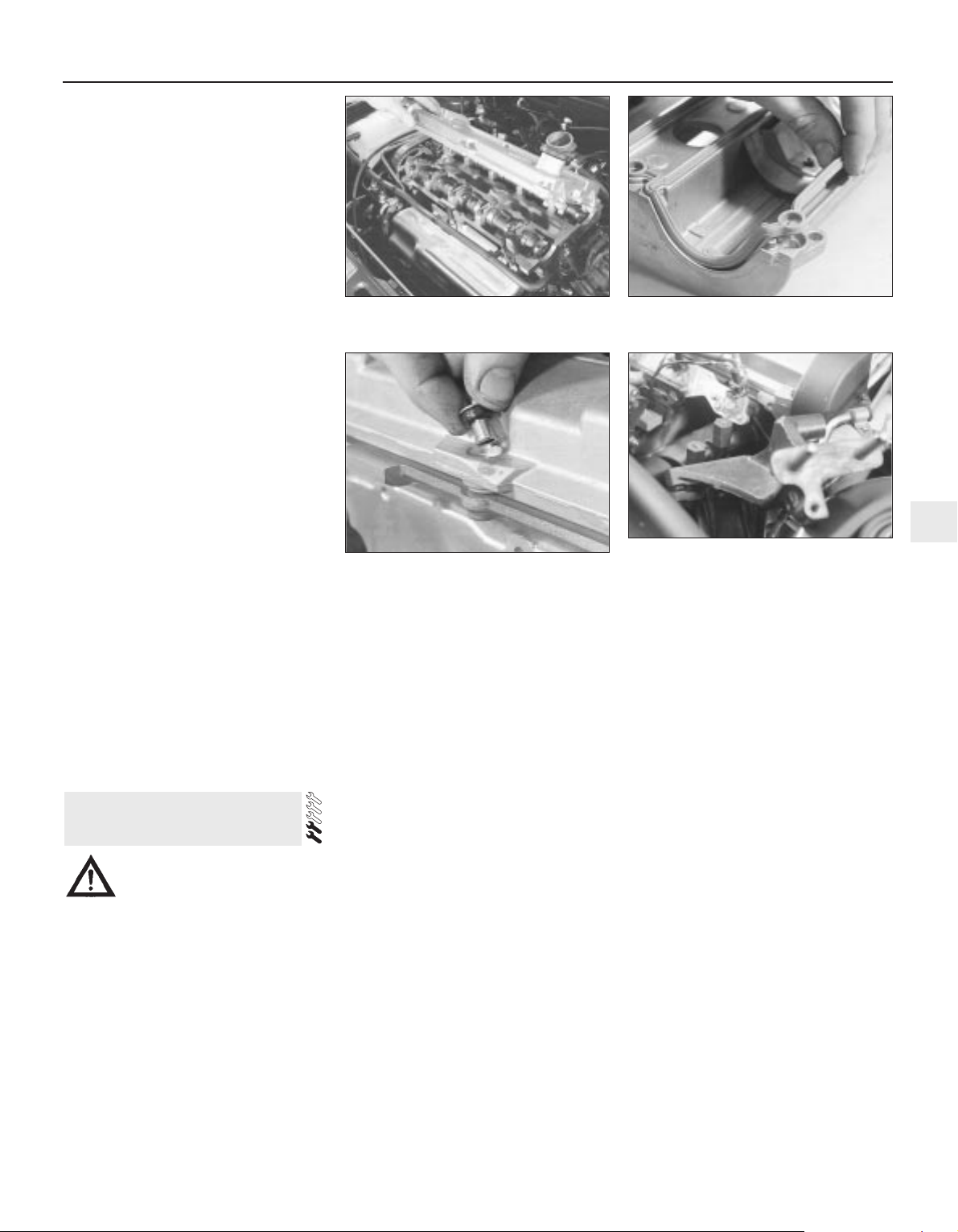
throttle linkage as described in Chapter 4.
Where fitted, disconnect also the cruise
control actuator cable (see Chapter 12).
3 Remove the timing belt upper cover (see
Section 9).
4 Disconnect the crankcase breather hose
from the cylinder head cover union (see
illustration).
5 Unplug the HT leads from the spark plugs
and withdraw them, unclipping the leads from
the cover.
6 Working progressively, unscrew the
cylinder head cover retaining bolts, noting the
spacer sleeve and rubber seal at each, then
withdraw the cover (see illustration).
7 Discard the cover gasket; this must be
renewed whenever it is disturbed. Check that
the sealing faces are undamaged, and that
the rubber seal at each retaining bolt is
serviceable; renew any worn or damaged
seals.
8 On refitting, clean the cover and cylinder
head gasket faces carefully, then fit a new
gasket to the cover, ensuring that it locates
correctly in the cover grooves (see
illustration).
9 Refit the cover to the cylinder head, then
insert the rubber seal and spacer sleeve at
each bolt location (see illustration). Start all
bolts finger-tight, ensuring that the gasket
remains seated in its groove.
10 Working in a diagonal sequence from the
centre outwards, and in two stages (see
Specifications), tighten the cover bolts to the
specified torque wrench setting.
11 Refit the HT leads, clipping them into
place so that they are correctly routed; each
is numbered, and can also be identified by
the numbering on its respective coil terminal.
12 Reconnect the crankcase breather hose,
and refit the timing belt upper cover.
Reconnect and adjust the accelerator cable,
then refit the air cleaner assembly cover with
the air mass meter, the resonator and the
plenum chamber (see Chapter 4).
Warning: Petrol is extremely
flammable, so take extra
precautions when disconnecting
any part of the fuel system. Don’t smoke,
or allow naked flames or bare light bulbs in
or near the work area. Don’t work in a
garage where a natural gas appliance
(such as a clothes dryer or water heater) is
installed. If you spill petrol on your skin,
rinse it off immediately. Have a fire
extinguisher rated for petrol fires handy,
and know how to use it.
Removal
1 Park the vehicle on firm, level ground,
apply the handbrake firmly, and slacken the
nuts securing the right-hand front roadwheel.
2 Relieve the fuel system pressure (see
Chapter 4).
3 Disconnect the battery negative (earth) lead
- see Chapter 5, Section 1.
4 Unplugging the two electrical connectors
and disconnecting the vacuum hose (where
fitted), remove the air cleaner assembly cover
with the air mass meter, the resonator and the
plenum chamber (see Chapter 4).
5 Disconnect the accelerator cable from the
throttle linkage as described in Chapter 4 where fitted, disconnect also the cruise
control actuator cable (see Chapter 12).
6 Disconnect the crankcase breather hose
from the cylinder head cover union.
7 Unbolt the upper part of the exhaust
manifold heat shield; unclip the coolant hose
to allow it to be withdrawn. Slacken the
sleeve nut securing the EGR pipe to the
manifold, remove the two screws securing
the pipe to the ignition coil bracket, then
unscrew the sleeve nut securing the pipe to
the EGR valve - see Chapter 6 for full details if
required.
8 Remove the two screws securing the wiring
“rail” to the top of the manifold - this is simply
so that it can be moved as required to reach
the manifold bolts. Unplug their electrical
connectors to disconnect the camshaft
position sensor and the coolant temperature
sensor, then unclip the wiring from the ignition
coil bracket, and secure it to the manifold.
9 Remove the three screws securing the
wiring “rail” to the rear of the manifold.
Releasing its wire clip, unplug the large
electrical connector (next to the fuel pressure
regulator) to disconnect the wiring of the
manifold components from the engine wiring
loom.
10 Marking or labelling them as they are
unplugged, disconnect the vacuum hoses as
follows:
(a) One from the rear of the throttle housing
(only the one hose - there is no need to
disconnect the second hose running to
the fuel pressure regulator).
(b) One from the union on the manifold’s left-
hand end.
(c) The braking system vacuum servo unit
hose (see Chapter 9 for details).
(d) One from the Exhaust Gas Recirculation
(EGR) valve.
11 Equalise the pressure in the fuel tank by
removing the filler cap, then undo the fuel
feed and return lines connecting the engine to
the chassis (see Chapter 4). Plug or cap all
open fittings.
12 Unbolt the power steering high-pressure
pipe and the earth lead from the cylinder
head rear support plate/engine lifting eye,
then unscrew the bolt securing the support
plate/lifting eye to the alternator mounting
bracket.
13 Unscrew the six nuts securing the
engine/transmission right-hand mounting
bracket, then withdraw the bracket.
14 Remove the alternator (see Chapter 5).
15 Unbolt the alternator mounting bracket
from the rear of the cylinder block and
withdraw it, together with the cylinder head
rear support plate/engine lifting eye (see
illustration).
6 Inlet manifold -
removal and refitting
In-car engine repair procedures 2A•7
2A
5.8 Ensure gasket is located correctly in
cover groove
5.6 Removing cylinder head cover
5.9 Ensure rubber seal is fitted to each
cover bolt spacer, as shown
6.15 Alternator mounting bracket must be
unbolted from rear of cylinder block to
permit access to inlet manifold nut
Page 48
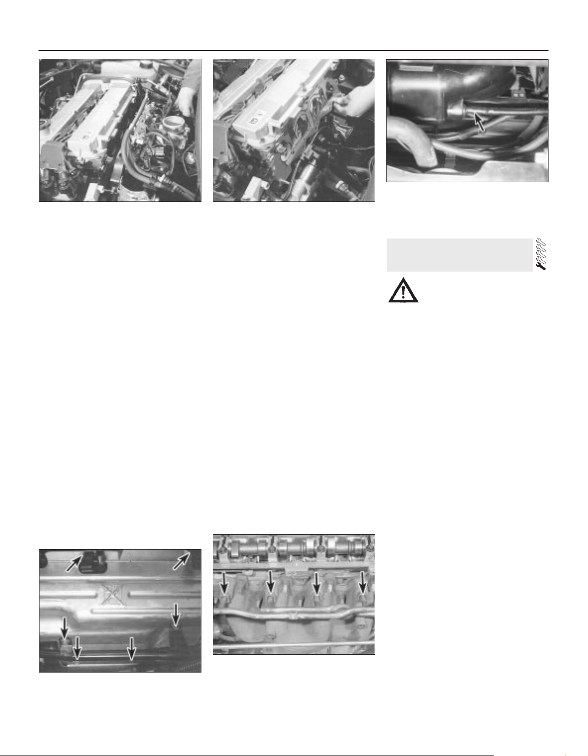
16 Unscrew the bolts and nuts securing the
manifold to the cylinder head and withdraw it
(see illustration). Take care not to damage
vulnerable components such as the EGR pipe
and valve as the manifold assembly is
manoeuvred out of the engine compartment.
Refitting
17 Refitting is the reverse of the removal
procedure, noting the following points:
(a) When using a scraper and solvent to
remove all traces of old gasket material
and sealant from the manifold and
cylinder head, be careful to ensure that
you do not scratch or damage the
material of either; the cylinder head is of
aluminium alloy, while the manifold is a
plastics moulding - any solvents used
must be suitable for this application. If the
gasket was leaking, have the mating
surfaces checked for warpage at an
automotive machine shop. While it may
be possible to have the cylinder head
gasket surface skimmed if necessary, to
remove any distortion, the manifold must
be renewed if it is found to be warped,
cracked - check with special care around
the mounting points for components such
as the idle speed control valve and EGR
pipe - or otherwise faulty.
(b) Provided the relevant mating surfaces are
clean and flat, a new gasket will be
sufficient to ensure the joint is gas-tight.
Do not use any kind of silicone-based
sealant on any part of the fuel system or
inlet manifold.
(c) Fit a new gasket, then locate the manifold
on the head and install the nuts and bolts
(see illustration).
(d) Tighten the nuts/bolts in three or four
equal steps to the torque listed in this
Chapter’s Specifications. Work from the
centre outwards, to avoid warping the
manifold.
(e) Refit the remaining parts in the reverse
order of removal - tighten all fasteners to
the torque wrench settings specified.
(f) When reassembling the
engine/transmission right-hand mounting,
renew the self-locking nuts, and do not
allow the mounting to twist as the middle
two of the bracket’s six nuts are
tightened.
(g) Before starting the engine, check the
accelerator cable for correct adjustment
and the throttle linkage for smooth
operation.
(h) When the engine is fully warmed up,
check for signs of fuel, intake and/or
vacuum leaks (see illustration).
(i) Road test the vehicle, and check for
proper operation of all disturbed
components.
Warning: The engine must be
completely cool before beginning
this procedure.
Note: In addition to the new gasket and any
other parts, tools or facilities needed to carry
out this operation, a new plastic guide sleeve
will be required on reassembly.
Removal
1 Disconnect the battery negative (earth) lead
- see Chapter 5, Section 1.
2 Unbolt the resonator support bracket from
the engine compartment front crossmember,
slacken the two clamp screws securing the
resonator to the air mass meter and plenum
chamber hoses, then swing the resonator up
clear of the thermostat housing (see Chapter 4).
3 Drain the cooling system (see Chapter 1).
4 Disconnect the coolant hose and the
coolant pipe/hose from the thermostat
housing; secure them clear of the working
area.
5 Unbolt the exhaust manifold heat shield,
and withdraw both parts of the shield (see
illustration). Apply penetrating oil to the EGR
pipe sleeve nut, and to the exhaust manifold
mounting nuts (also to the pulse-air system
sleeve nuts, if they are to be unscrewed).
6 Unscrew the sleeve nut securing the EGR
pipe to the manifold, remove the two screws
securing the pipe to the ignition coil bracket,
then slacken the sleeve nut securing the pipe
to the EGR valve - see Chapter 6 for full
details if required.
7 While the manifold can be removed with
the pulse-air system components attached unbolt the filter housing and disconnect its
vacuum hose if this is to be done - it is easier
to remove the pulse-air assembly first, as
described in Chapter 6 (see illustration).
8 Unplugging the oxygen sensor electrical
connector to avoid straining its wiring,
unscrew the nuts to disconnect the exhaust
system front downpipe from the manifold (see
Chapter 4).
7 Exhaust manifold - removal,
inspection and refitting
2A•8 In-car engine repair procedures
6.16 Withdrawing inlet manifold - take
care not to damage delicate components
6.17A Always renew inlet manifold gasket
- do not rely on sealants
6.17B Check all disturbed components braking system vacuum servo unit hose
(arrowed) shown here - for leaks on
reassembly
7.5 Exhaust manifold heat shield upper
part securing bolts (arrowed)
7.7 Pulse-air system (sleeve nuts arrowed)
need not be removed unless required -
assembly can be withdrawn with exhaust
manifold
Page 49
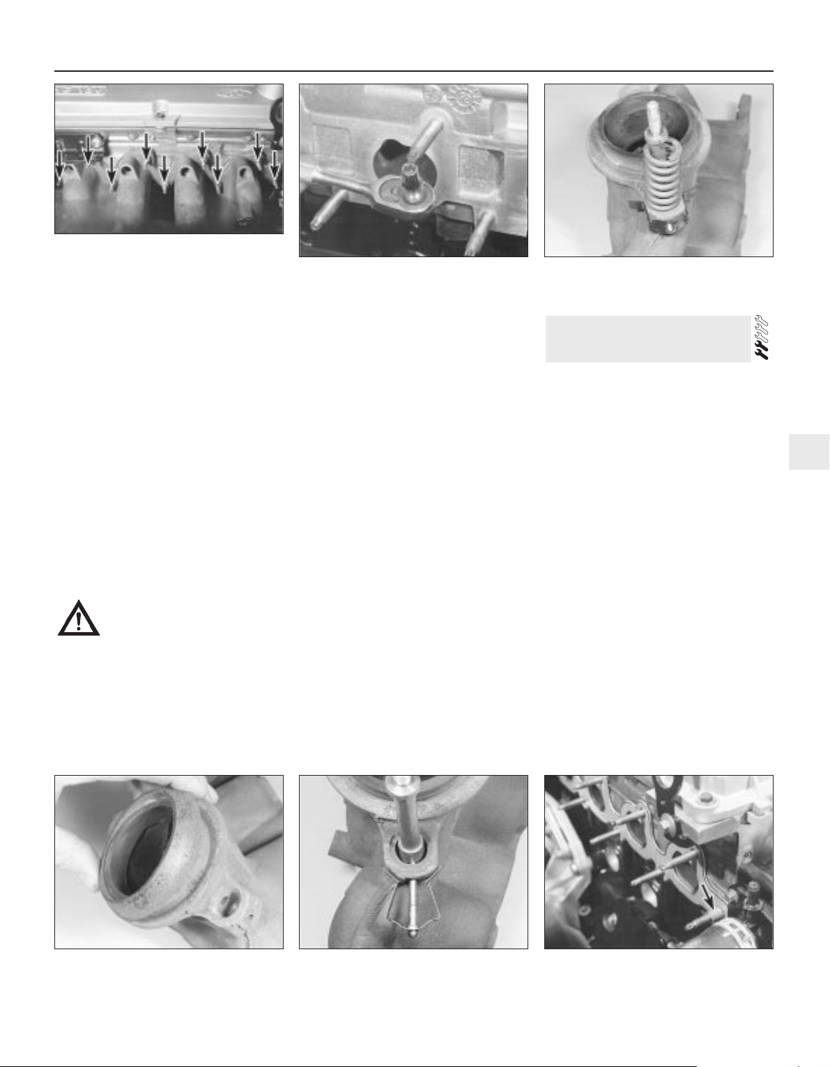
9 Remove the nuts and detach the manifold
and gasket (see illustration). Take care not
to damage vulnerable components such as
the EGR pipe as the manifold assembly is
manoeuvred out of the engine compartment.
When removing the manifold with the engine
in the vehicle, additional clearance can be
obtained by unscrewing the studs from the
cylinder head; a female Torx-type socket will
be required (see illustration).
10 Always fit a new gasket on reassembly, to
carefully-cleaned components (see below).
Do not attempt to re-use the original gasket.
Inspection
11 Use a scraper to remove all traces of old
gasket material and carbon deposits from the
manifold and cylinder head mating surfaces. If
the gasket was leaking, have the manifold
checked for warpage at an automotive
machine shop, and have it resurfaced if
necessary.
Caution: When scraping, be very
careful not to gouge or scratch
the delicate aluminium alloy
cylinder head.
12 Provided both mating surfaces are clean
and flat, a new gasket will be sufficient to
ensure the joint is gas-tight. Do not use any
kind of exhaust sealant upstream of the
catalytic converter.
13 Note that the downpipe is secured to the
manifold by two bolts, with a coil spring,
spring seat and self-locking nut on each. On
refitting, tighten the nuts until they stop on the
bolt shoulders; the pressure of the springs will
then suffice to make a leakproof joint (see
illustrations).
14 Do not overtighten the nuts to cure a leak
- the bolts will shear; renew the gasket and
the springs if a leak is found. The bolts
themselves are secured by spring clips to the
manifold, and can be renewed easily if
damaged (see illustration).
Refitting
15 Refitting is the reverse of the removal
procedure, noting the following points:
(a) Position a new gasket over the cylinder
head studs, and fit a new plastic guide
sleeve to the stud nearest to the
thermostat housing, so that the manifold
will be correctly located (see illustration).
Do not refit the manifold without this
sleeve.
(b) Refit the manifold, and finger-tighten the
mounting nuts.
(c) Working from the centre out, and in three
or four equal steps, tighten the nuts to the
torque wrench setting given in the
Specifications Section of this Chapter.
(d) Refit the remaining parts in the reverse
order of removal. Tighten all fasteners to
the specified torque wrench settings.
(e) Refill the cooling system (see Chapter 1).
(f) Run the engine, and check for exhaust
leaks. Check the coolant level when fully
warmed-up to normal operating
temperature.
1 Remove the auxiliary drivebelt - either
remove the drivebelt completely, or just
secure it clear of the crankshaft pulley,
depending on the work to be carried out (see
Chapter 1).
2 If necessary, rotate the crankshaft until the
timing marks align (see Section 4).
3 The crankshaft must now be locked to
prevent its rotation while the pulley bolt is
unscrewed. Proceed as follows:
(a) If the engine/transmission is still installed
in the vehicle:
(1)If the vehicle is fitted with manual
transmission, select top gear, and have an
assistant apply the brakes hard.
(2)If the vehicle is fitted with automatic
transmission, unbolt the small metal cover
plate from the sump, and use a large
screwdriver or similar to lock the
driveplate ring gear teeth while an
assistant slackens the pulley bolt; take
care not to damage the teeth or the
surrounding castings when using this
method.
(b) If the engine/transmission has been
removed but not yet separated:
(1)If the vehicle is fitted with manual
transmission, remove the starter motor
(see Chapter 5) and lock the flywheel
8 Crankshaft pulley -
removal and refitting
In-car engine repair procedures 2A•9
2A
7.13B Renew exhaust system downpipeto-manifold gasket to prevent leaks
7.14 Release spring clip to extract
securing bolt from manifold, when required
7.15 Fit plastic guide sleeve to stud
arrowed when refitting exhaust manifold
7.9A Unscrew nuts (arrowed) to remove
exhaust manifold . . .
7.9B . . . studs can be unscrewed also, if
required, to provide additional working
space
7.13A Showing exhaust downpipe-to-
manifold securing bolts - note coil spring,
and shoulder on bolt
Page 50
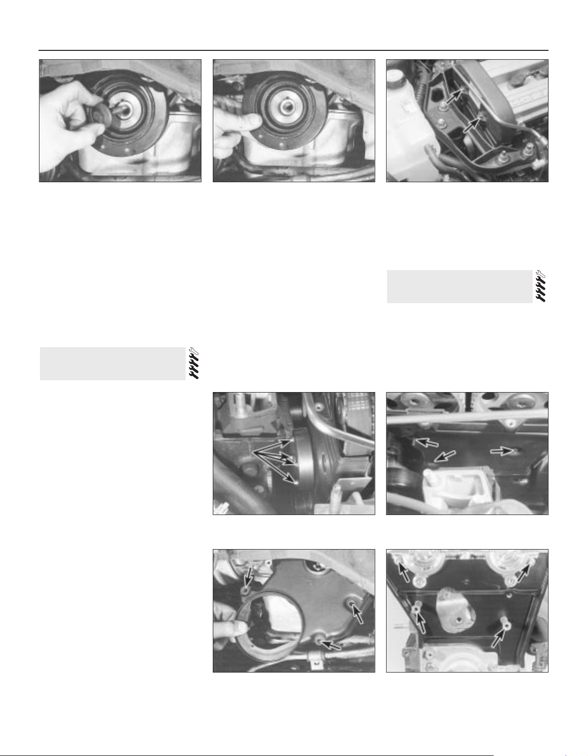
using the method outlined in (2) above.
(2)If the vehicle is fitted with automatic
transmission, see (2) above.
(c) If the engine/transmission has been
removed and separated, use the method
shown in illustration 21.11.
4 Unscrew the pulley bolt and remove the
pulley (see illustrations).
5 Refitting is the reverse of the removal
procedure; ensure that the pulley’s keyway is
aligned with the crankshaft’s locating key,
and tighten the pulley bolt to the specified
torque wrench setting.
Upper cover
1 Unscrew the cover’s two mounting bolts
and withdraw it (see illustration).
2 Refitting is the reverse of the removal
procedure; ensure the cover edges engage
correctly with each other, and note the torque
wrench setting specified for the bolts.
Middle cover
3 Unscrew the six nuts securing the
engine/transmission right-hand mounting
bracket, then withdraw the bracket.
4 Slacken the water pump pulley bolts.
5 Remove the timing belt upper cover (see
paragraph 1 above).
6 Remove the auxiliary drivebelt (see Chapter 1).
7 Unbolt and remove the water pump pulley
(see illustration).
8 Unscrew the middle cover fasteners (one
bolt at the front, one at the lower rear, one
stud at the top rear) and withdraw the cover
(see illustration).
9 Refitting is the reverse of the removal
procedure. Ensure the cover edges engage
correctly with each other, and note the torque
wrench settings specified for the various
fasteners. When reassembling the engine/
transmission right-hand mounting, renew the
self-locking nuts, and do not allow the
mounting to twist as the middle two of the
bracket’s six nuts are tightened.
Lower cover
10 Remove the crankshaft pulley (see
Section 8).
11 Unscrew the cover’s three securing bolts
and withdraw it (see illustration).
12 Refitting is the reverse of the removal
procedure; ensure the cover edges engage
correctly with each other, and note the torque
wrench settings specified for the various
fasteners.
Inner shield
13 Remove the timing belt, its tensioner
components and the camshaft toothed
pulleys (see Sections 10 and 11).
14 The shield is secured to the cylinder head
by two bolts at the top, and by two studs
lower down; unscrew these and withdraw the
shield (see illustration).
15 Refitting is the reverse of the removal
procedure; note the torque wrench settings
specified for the various fasteners.
Note: To carry out this operation, a new
timing belt (where applicable), a new cylinder
head cover gasket, and some special tools
(see text) will be required. If the timing belt is
being removed for the first time since the
vehicle left the factory, a tensioner spring and
retaining pin must be obtained for fitting on
reassembly.
10 Timing belt - removal,
refitting and adjustment
9 Timing belt covers -
removal and refitting
2A•10 In-car engine repair procedures
8.4A Unscrew pulley bolt to release
crankshaft pulley
8.4B Ensure pulley is located on
crankshaft Woodruff key on reassembly
9.1 Remove bolts (arrowed) to release
timing belt upper cover
9.8 Remove fasteners (arrowed) to release
timing belt middle cover
9.7 Slacken water pump pulley bolts and
remove pulley
9.11 Removing timing belt lower cover bolt locations arrowed
9.14 Timing belt inner shield fasteners
(arrowed)
Page 51
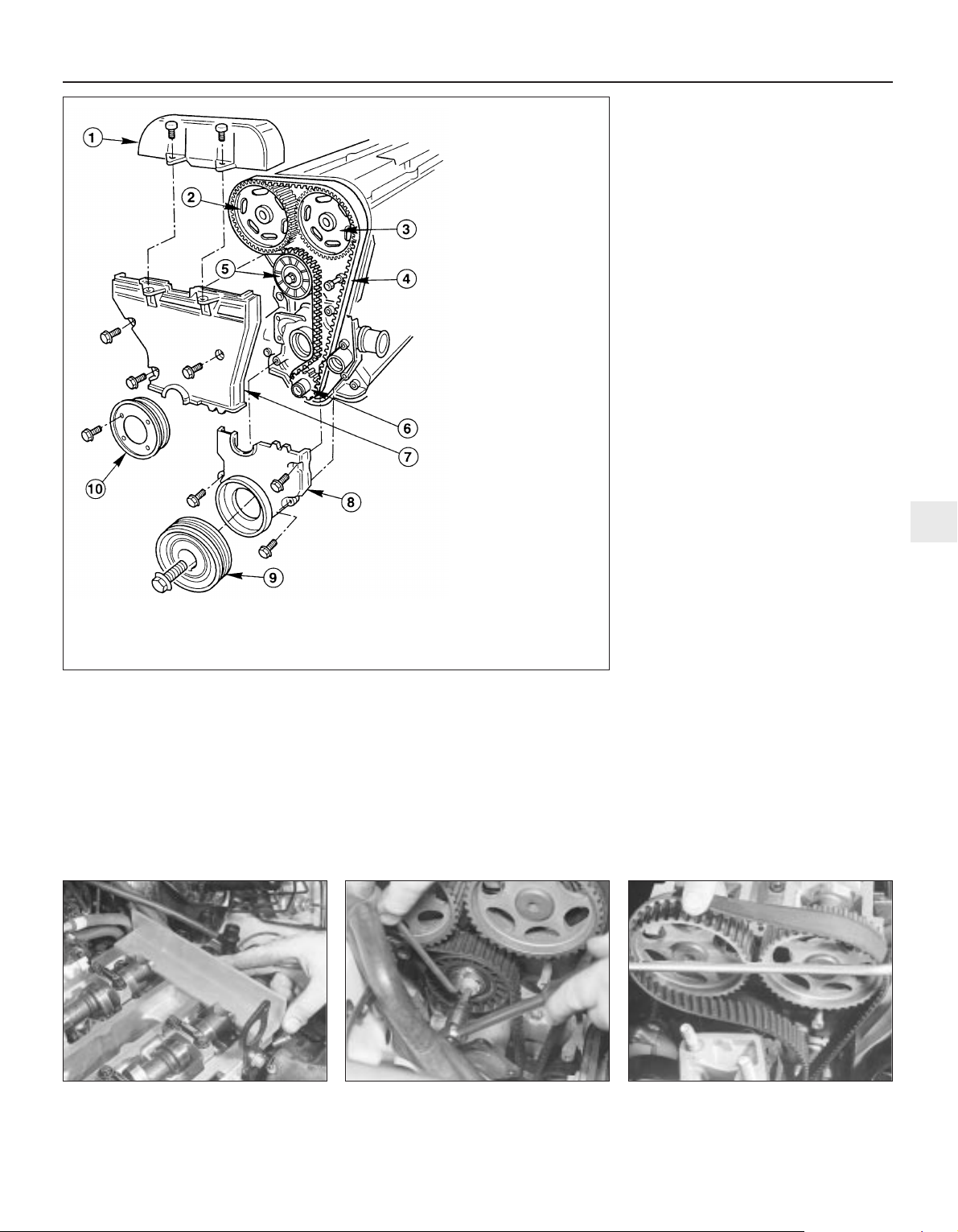
1 With the vehicle parked on firm level
ground, open the bonnet and disconnect the
battery negative (earth) lead - see Chapter 5,
Section 1 (see illustration).
2 Unbolt the power steering high-pressure
pipe from the cylinder head rear support
plate/engine lifting eye, and from the front
support plate/pump bracket.
3 Unscrew the six nuts securing the
engine/transmission right-hand mounting
bracket, then withdraw the bracket.
4 Slacken the water pump pulley bolts.
5 Remove the cylinder head cover (see
Section 5).
6 Remove the spark plugs, covering their
holes with clean rag, to prevent dirt or other
foreign bodies from dropping in (see Chapter 1).
7 Remove the auxiliary drivebelt (see Chapter 1).
8 Rotate the crankshaft clockwise until the
second pair of notches in the pulley rim align
with the edge of the sump mark, so that Nos
1 and 4 cylinders are at TDC (see Section 4).
9 Unbolt and remove the water pump pulley
and the auxiliary drivebelt idler pulley.
10 Obtain Ford service tool 21-162, or
fabricate a substitute from a strip of metal
5 mm thick (while the strip’s thickness is
critical, its length and width are not, but
should be approximately 180 to 230 mm by
20 to 30 mm). Check that Nos 1 and 4
cylinders are at Top Dead Centre (TDC) - No 1
on the compression stroke - by resting this
tool on the cylinder head mating surface, and
sliding it into the slot in the left-hand end of
both camshafts (see illustration). The tool
should slip snugly into both slots while resting
on the cylinder head mating surface; if one
camshaft is only slightly out of alignment, it is
permissible to use an open-ended spanner to
rotate the camshaft gently and carefully until
the tool will fit.
11 If both camshaft slots (they are machined
significantly off-centre) are below the level of
the cylinder head mating surface, rotate the
crankshaft through one full turn clockwise
and fit the tool again; it should now fit as
described in the previous paragraph.
12 With the camshaft aligning tool remaining
in place, remove the crankshaft pulley. Do not
use the locked camshafts to prevent the
crankshaft from rotating - use only the locking
methods described in Section 8.
13 Remove the timing belt lower and middle
covers (see Section 9).
14 With the camshaft aligning tool still in
place, slacken the tensioner bolt, and use an
Allen key inserted into its centre to rotate the
tensioner clockwise as far as possible away
from the belt; retighten the bolt to secure the
tensioner clear of the timing belt (see
illustration).
15 If the timing belt is to be re-used, use
white paint or similar to mark its direction of
rotation, and note from the manufacturer’s
markings which way round it is fitted.
Withdraw the belt (see illustration). Do not
rotate the crankshaft until the timing belt is
refitted.
16 If the belt is being removed for reasons
other than routine renewal, check it carefully
for any signs of uneven wear, splitting, cracks
(especially at the roots of the belt teeth) or
In-car engine repair procedures 2A•11
2A
10.10 Fit camshaft aligning tool to ensure
engine is locked with Nos 1 and 4 cylinders
at TDC
10.14 Slacken tensioner bolt, and use
Allen key to rotate tensioner away from
timing belt . . .
10.15 . . . then withdraw timing belt
10.1 Timing belt and cover details
1 Timing belt upper cover
2 Inlet camshaft toothed pulley
3 Exhaust camshaft toothed pulley
4 Timing belt
5 Timing belt tensioner
6 Crankshaft toothed pulley
7 Timing belt middle cover
8 Timing belt lower cover
9 Crankshaft pulley
10 Water pump pulley
Page 52
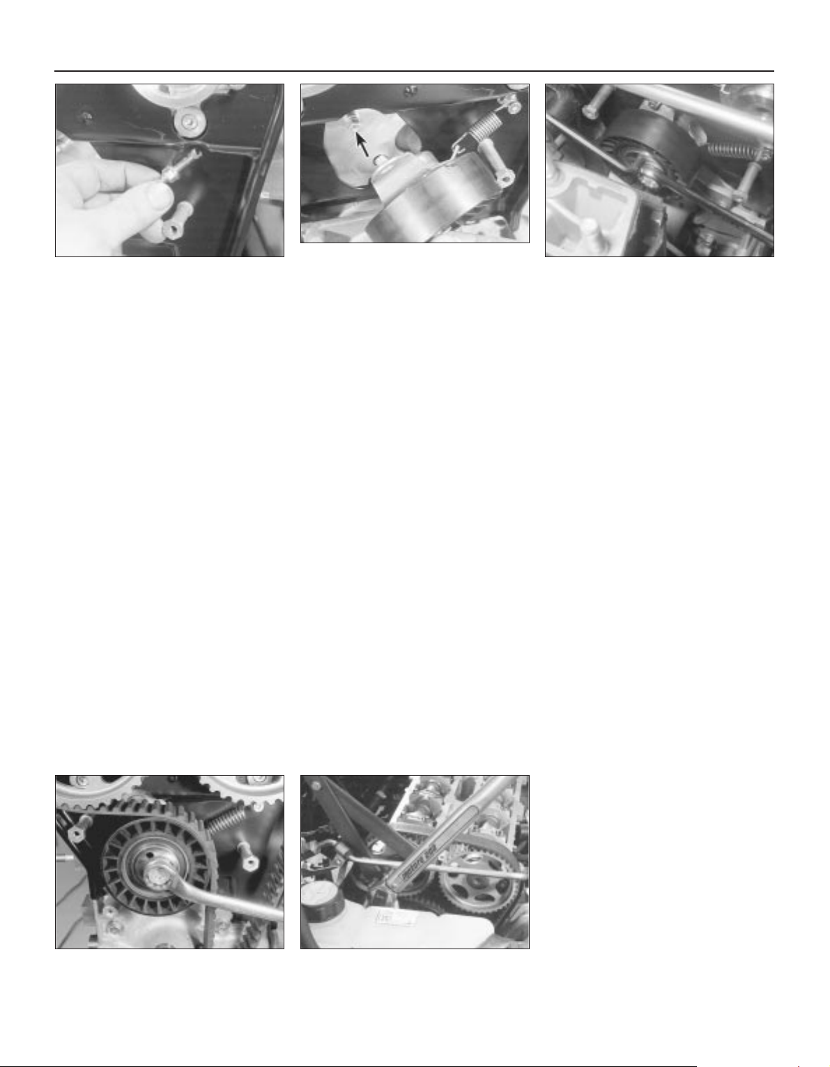
contamination with oil or coolant. Renew the
belt if there is the slightest doubt about its
condition. As a safety measure, the belt must
be renewed as a matter of course at the
intervals given in Chapter 1; if its history is
unknown, the belt should be renewed
irrespective of its apparent condition
whenever the engine is overhauled. Similarly,
check the tensioner spring (where fitted),
renewing it if there is any doubt about its
condition. Check also the toothed pulleys for
signs of wear or damage, and ensure that the
tensioner and guide pulleys rotate smoothly
on their bearings; renew any worn or
damaged components. If signs of oil or
coolant contamination are found, trace the
source of the leak and rectify it, then wash
down the engine timing belt area and related
components, to remove all traces of oil or
coolant.
17 On reassembly, temporarily refit the
crankshaft pulley, to check that the pulley
notches and sump rib are aligned as
described in paragraph 8 above, then ensure
that both camshafts are aligned at TDC by
the special tool (paragraph 10). If the engine
is being reassembled after major dismantling,
both camshaft toothed pulleys should be free
to rotate on their respective camshafts; if the
timing belt alone is being renewed, both
pulleys should still be securely fastened.
18 A holding tool will be required to prevent
the camshaft toothed pulleys from rotating
while their bolts are slackened and
retightened; either obtain Ford service tool
15-030A, or fabricate a substitute as follows.
Find two lengths of steel strip, one
approximately 600 mm long and the other
about 200 mm, and three bolts with nuts and
washers; one nut and bolt forming the pivot of
a forked tool, with the remaining nuts and
bolts at the tips of the “forks”, to engage with
the pulley spokes as shown in the
accompanying illustrations. Note: Do not use
the camshaft aligning tool (whether genuine
Ford or not) to prevent rotation while the
camshaft toothed pulley bolts are slackened
or tightened; the risk of damage to the
camshaft concerned and to the cylinder head
is far too great. Use only a forked holding tool
applied directly to the pulleys, as described.
19 If it is being fitted for the first time, screw
the timing belt tensioner spring retaining pin
into the cylinder head, tightening it to the
specified torque wrench setting. Unbolt the
tensioner, hook the spring on to the pin and
the tensioner backplate, then refit the
tensioner, engaging its backplate on the
locating peg (see illustrations).
20 In all cases, slacken the tensioner bolt (if
necessary), and use an Allen key inserted into
its centre to rotate the tensioner clockwise as
far as possible against spring tension, then
retighten the bolt to secure the tensioner (see
illustration).
21 Fit the timing belt; if the original is being
refitted, ensure that the marks and notes
made on removal are followed, so that the
belt is refitted the same way round, and to run
in the same direction. Starting at the
crankshaft toothed pulley, work anticlockwise around the camshaft toothed
pulleys and tensioner, finishing off at the rear
guide pulley. The front run, between the
crankshaft and the exhaust camshaft toothed
pulleys, must be kept taut, without altering
the position either of the crankshaft or of the
camshaft(s) - if necessary, the position of the
camshaft toothed pulleys can be altered by
rotating each on its camshaft (which remains
fixed by the aligning tool). Where the pulley is
still fastened, use the holding tool described
in paragraph 18 above to prevent the pulley
from rotating while its retaining bolt is
slackened - the pulley can then be rotated on
the camshaft until the belt will slip into place;
retighten the pulley bolt.
22 When the belt is in place, slacken the
tensioner bolt gently until the spring pulls the
tensioner against the belt; the tensioner
should be retained correctly against the
timing belt inner shield and cylinder head, but
must be just free to respond to changes in
belt tension (see illustration).
23 Tighten both camshaft toothed pulley
bolts (or check that they are tight, as
applicable) and remove the camshaft aligning
tool. Temporarily refit the crankshaft pulley,
and rotate the crankshaft through two full
turns clockwise to settle and tension the
timing belt, returning the crankshaft (pulley
notches) to the position described in
paragraph 8 above. Refit the camshaft
aligning tool; it should slip into place as
described in paragraph 10. If all is well,
proceed to paragraph 26 below.
24 If one camshaft is only just out of line, fit
the forked holding tool to its toothed pulley,
adjust its position as required, and check that
any slack created has been taken up by the
tensioner; rotate the crankshaft through two
further turns clockwise, and refit the camshaft
aligning tool to check that it now fits as it
should. If all is well, proceed to paragraph 26
below.
25 If either camshaft is significantly out of
line, use the holding tool described in
paragraph 18 above to prevent its pulley from
rotating while its retaining bolt is slackened the camshaft can then be rotated (gently and
carefully, using an open-ended spanner) until
2A•12 In-car engine repair procedures
10.19A Fitting tensioner spring retaining
pin
10.19B Hook spring onto tensioner and
refit as shown - engage tensioner
backplate on locating peg (arrowed) . . .
10.20 . . . then use Allen key to position
tensioner so that timing belt can be refitted
10.22 Slacken tensioner bolt to give initial
belt tension
10.25 Using forked holding tool while
camshaft toothed pulley bolt is tightened
Page 53
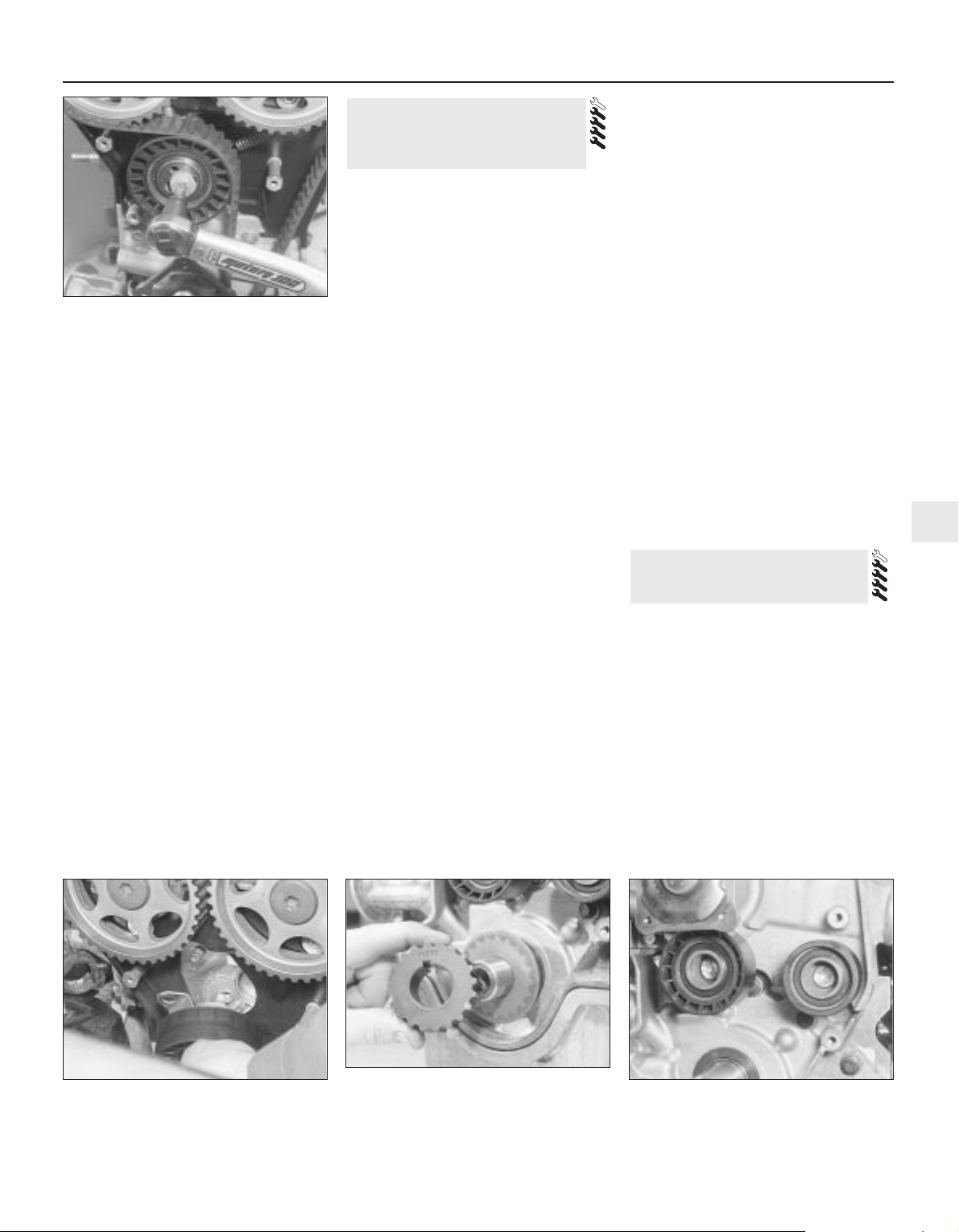
the camshaft aligning tool will slip into place;
take care not to disturb the relationship of the
pulley to the timing belt. Without disturbing
the pulley’s new position on the camshaft,
tighten the pulley bolt to its specified torque
wrench setting (see illustration). Remove the
camshaft aligning tool, rotate the crankshaft
through two further turns clockwise and refit
the tool to check that it now fits as it should.
26 When the timing belt has been settled at
its correct tension, and the camshaft aligning
tool fits correctly when the crankshaft pulley
notches are exactly aligned, tighten the
tensioner bolt to its specified torque wrench
setting (see illustration). Fitting the forked
holding tool to the spokes of each pulley in
turn, check that the pulley bolts are tightened
to their specified torque wrench setting.
Remove the camshaft aligning tool, rotate the
crankshaft through two further turns
clockwise, and refit the tool to make a final
check that it fits as it should.
27 The remainder of the reassembly
procedure is the reverse of removal, noting
the following points:
(a) Tighten all fasteners to the torque wrench
settings specified.
(b) When reassembling the
engine/transmission right-hand mounting,
renew the self-locking nuts, and do not
allow the mounting to twist as the middle
two of the bracket’s six nuts are
tightened.
Tensioner
Note: If the tensioner is being removed for the
first time since the vehicle left the factory, a
tensioner spring and retaining pin must be
obtained for fitting on reassembly.
1 While it is possible to reach the tensioner
once the timing belt upper and middle covers
only have been removed (see Section 9), the
whole procedure outlined below must be
followed, to ensure that the valve timing is
correctly reset once the belt’s tension has
been disturbed.
2 Release the tension from the timing belt as
described in Section 10, paragraphs 1 to 14.
3 Unscrew the tensioner bolt and withdraw
the tensioner, unhooking the spring, if fitted
(see illustration). Check the tensioner and
spring as described in paragraph 16 of
Section 10.
4 On reassembly, if it is being fitted for the
first time, screw the timing belt tensioner
spring retaining pin into the cylinder head,
tightening it to the specified torque wrench
setting. Hook the spring onto the pin and the
tensioner backplate, then refit the tensioner,
engaging its backplate on the locating peg.
5 Use an Allen key inserted into its centre to
rotate the tensioner clockwise as far as
possible against spring tension, then tighten
the bolt to secure the tensioner.
6 Reassemble, checking the camshaft
alignment (valve timing) and setting the timing
belt tension, as described in paragraphs 22 to
27 of Section 10.
Camshaft and crankshaft toothed
pulleys
7 While it may be possible to remove any of
these pulleys once their respective covers
have been removed, the complete timing belt
removal/refitting procedure (see Section 10)
must be followed, to ensure that the valve
timing is correctly reset once the belt’s
tension has been disturbed.
8 With the timing belt removed, the camshaft
toothed pulleys can be detached once their
retaining bolts have been unscrewed as
described in paragraphs 18 and 21 of Section
10. The crankshaft toothed pulley can be
pulled off the end of the crankshaft once the
crankshaft (grooved) pulley and the timing
belt have been removed. Note the “FRONT”
marking identifying the pulley’s outboard
face, and the thrustwasher behind it; note
which way round the thrustwasher is fitted
(see illustration). Note the pulley-locating
Woodruff key; if this is loose, it should be
removed for safe storage with the pulley.
9 Check the pulleys as described in
paragraph 16 of Section 10.
10 Refitting is the reverse of the removal
procedure.
Timing belt guide pulleys
11 Remove the timing belt covers (see
Section 9).
12 Unbolt and withdraw the pulley(s); check
their condition as described in paragraph 16
of Section 10.
13 Refitting is the reverse of the removal
procedure; tighten the pulley bolts to the
specified torque wrench setting (see
illustration).
Note: While it is possible to reach either oil
seal, once the respective toothed pulley has
been removed (see Section 11) to allow the
seal to be prised out, this procedure is not
recommended. Not only are the seals very
soft, making this difficult to do without risk of
damage to the seal housing, but it would be
very difficult to ensure that the valve timing
and the timing belt’s tension, once disturbed,
are correctly reset. Owners are advised to
follow the whole procedure outlined below.
1 Release the tension from the timing belt as
described in Section 10, paragraphs 1 to 14.
Note: If the timing belt is found to be
contaminated by oil, remove it completely as
described, then renew the oil seal (see below).
Wash down the engine timing belt area and all
12 Camshaft oil seals - renewal
11 Timing belt tensioner and
toothed pulleys - removal,
inspection and refitting
In-car engine repair procedures 2A•13
2A
11.3 Removing timing belt tensioner
11.8 Note “FRONT” marking on outside
face of crankshaft toothed pulley - note
which way round thrustwasher behind is
fitted
11.13 Tighten timing belt guide pulley
bolts to specified torque settings on
refitting
10.26 When setting is correct, tighten
tensioner bolt to specified torque wrench
setting
Page 54
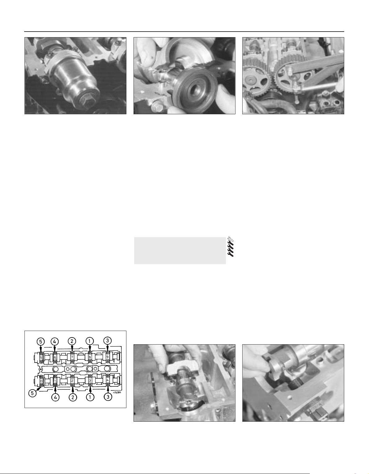
related components, to remove all traces of
oil. Fit a new belt on reassembly.
2 If the timing belt is still clean, slip it off the
toothed pulley, taking care not to twist it too
sharply; use the fingers only to handle the
belt. Do not rotate the crankshaft until the
timing belt is refitted. Cover the belt, and
secure it so that it is clear of the working area
and cannot slip off the remaining toothed
pulley.
3 Unfasten the pulley bolt and withdraw the
pulley (see Section 11).
4 Unbolt the camshaft right-hand bearing
cap, and withdraw the defective oil seal.
Clean the seal housing, and polish off any
burrs or raised edges, which may have
caused the seal to fail in the first place.
5 To fit a new seal, Ford recommend the use
of their service tool 21-009B, with a bolt
(10 mm thread size, 70 mm long) and a
washer, to draw the seal into place when the
camshaft bearing cap is bolted down; a
substitute can be made using a suitable
socket (see illustration). Grease the seal lips
and periphery to ease installation, and draw
the seal into place until it is flush with the
housing/bearing cap outer edge. Refit the
bearing cap, using sealant and tightening the
cap bolts as described in Section 13.
6 For most owners, the simplest answer will
be to grease the seal lips, and to slide it on to
the camshaft (until it is flush with the
housing’s outer edge). Refit the bearing cap,
using sealant and tightening the cap bolts as
described in Section 13 (see illustration).
Take care to ensure that the seal remains
absolutely square in its housing, and is not
distorted as the cap is tightened down.
7 Refit the pulley to the camshaft, tightening
the retaining bolt loosely, then slip the timing
belt back onto the pulley (refer to paragraphs 18 and 21 of Section 10) and tighten
the bolt securely.
8 The remainder of the reassembly
procedure, including checking the camshaft
alignment (valve timing) and setting the timing
belt tension, is as described in paragraphs 22
to 27 of Section 10.
Removal
1 Release the tension from the timing belt as
described in Section 10, paragraphs 1 to 14.
2 Either remove the timing belt completely
(Section 10, paragraphs 15 and 16) or slip it
off the camshaft toothed pulleys, taking care
not to twist it too sharply; use the fingers only
to handle the belt. Cover the belt, and secure
it so that it is clear of the working area. Do not
rotate the crankshaft until the timing belt is
refitted.
3 Unfasten the pulley bolts as described in
Section 10, paragraphs 18 and 21, and
withdraw the pulleys; while both are the same
and could be interchanged, it is good working
practice to mark them so that each is refitted
only to its original location (see illustration).
4 Working in the sequence shown, slacken
progressively, by half a turn at a time, the
camshaft bearing cap bolts (see illustration).
Work only as described, to release gradually
and evenly the pressure of the valve springs
on the caps.
5 Withdraw the caps, noting their markings
and the presence of the locating dowels, then
remove the camshafts and withdraw their oil
seals. The inlet camshaft can be identified by
the reference lobe for the camshaft position
sensor; therefore, there is no need to mark
the camshafts (see illustrations).
6 Obtain sixteen small, clean containers, and
number them 1 to 16. Using a rubber sucker,
withdraw each hydraulic tappet in turn, invert
it to prevent oil loss, and place it in its
respective container, which should then be
filled with clean engine oil (see illustrations).
Do not interchange the hydraulic tappets, or
the rate of wear will be much increased. Do
not allow them to lose oil, or they will take a
long time to refill on restarting the engine,
resulting in incorrect valve clearances.
Inspection
7 With the camshafts and hydraulic tappets
removed, check each for signs of obvious
13 Camshafts and hydraulic
tappets - removal,
inspection and refitting
2A•14 In-car engine repair procedures
12.5 Using socket and toothed pulley bolt
to install camshaft oil seal
12.6 Alternatively, seal can be inserted
when camshaft bearing cap is unbolted
13.3 Using forked holding tool while
camshaft toothed pulley bolt is slackened
13.4 Camshaft bearing cap slackening
sequence
Note: View from front of vehicle, showing
bearing cap numbers
13.5A Note locating dowels when
removing camshaft bearing caps
13.5B Inlet camshaft has lobe for
camshaft position sensor
Page 55
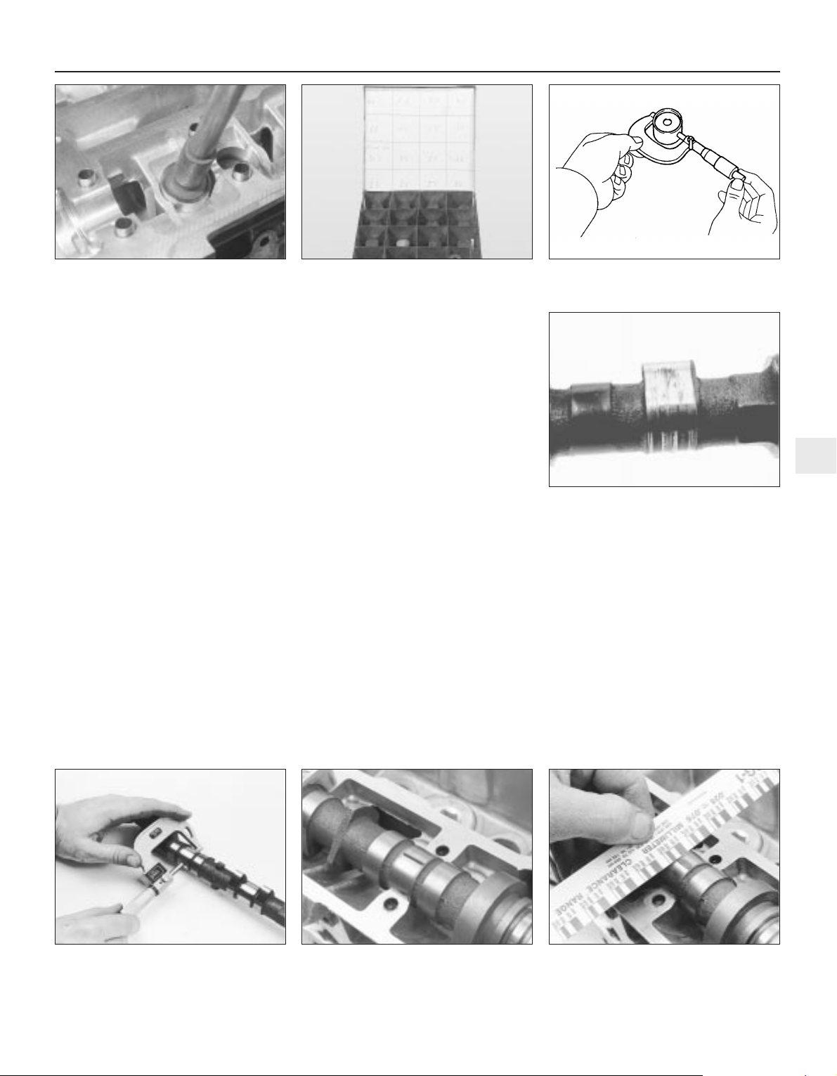
wear (scoring, pitting etc) and for ovality, and
renew if necessary.
8 Measure the outside diameter of each
tappet (see illustration) - take measurements
at the top and bottom of each tappet, then a
second set at right-angles to the first; if any
measurement is significantly different from
the others, the tappet is tapered or oval (as
applicable) and must be renewed. If the
necessary equipment is available, measure
the inside diameter of the corresponding
cylinder head bore. Compare the
measurements obtained to those given in the
Specifications Section of this Chapter; if the
tappets or the cylinder head bores are
excessively worn, new tappets and/or a new
cylinder head will be required.
9 If the engine’s valve components have
sounded noisy, particularly if the noise
persists after initial start-up from cold, there is
reason to suspect a faulty hydraulic tappet.
Only a good mechanic experienced in these
engines can tell whether the noise level is
typical, or if renewal of one or more of the
tappets is warranted. If faulty tappets are
diagnosed, and the engine’s service history is
unknown, it is always worth trying the effect
of renewing the engine oil and filter (see
Chapter 1), using only good-quality engine oil
of the recommended viscosity and
specification, before going to the expense of
renewing any of the tappets - refer also to the
advice in Section 1 of this Chapter.
10 Visually examine the camshaft lobes for
score marks, pitting, galling (wear due to
rubbing) and evidence of overheating (blue,
discoloured areas). Look for flaking away of
the hardened surface layer of each lobe (see
illustration). If any such signs are evident,
renew the component concerned.
11 Examine the camshaft bearing journals
and the cylinder head bearing surfaces for
signs of obvious wear or pitting. If any such
signs are evident, renew the component
concerned.
12 Using a micrometer, measure the
diameter of each journal at several points
(see illustration). If the diameter of any one
journal is less than the specified value, renew
the camshaft.
13 To check the bearing journal running
clearance, remove the hydraulic tappets, use
a suitable solvent and a clean lint-free rag to
clean carefully all bearing surfaces, then refit
the camshafts and bearing caps with a strand
of Plastigage across each journal (see
illustration). Tighten the bearing cap bolts to
the specified torque wrench setting (do not
rotate the camshafts), then remove the
bearing caps and use the scale provided to
measure the width of the compressed strands
(see illustration). Scrape off the Plastigage
with your fingernail or the edge of a credit
card - don’t scratch or nick the journals or
bearing caps.
14 If the running clearance of any bearing is
found to be worn to beyond the specified
service limits, fit a new camshaft and repeat
the check; if the clearance is still excessive,
the cylinder head must be renewed.
15 To check camshaft endfloat, remove the
hydraulic tappets, clean the bearing surfaces
carefully, and refit the camshafts and bearing
caps. Tighten the bearing cap bolts to the
specified torque wrench setting, then
measure the endfloat using a DTI (Dial Test
Indicator, or dial gauge) mounted on the
cylinder head so that its tip bears on the
camshaft right-hand end.
16 Tap the camshaft fully towards the gauge,
zero the gauge, then tap the camshaft fully
In-car engine repair procedures 2A•15
2A
13.12 Measure each journal diameter with
a micrometer - if any journal measures less
than the specified limit, renew the camshaft
13.13A Lay a strip of Plastigage on each
camshaft journal
13.13B Compare the width of the crushed
Plastigage to the scale on the envelope to
determine the running clearance
13.6A Removing hydraulic tappets 13.6B Hydraulic tappets must be stored as
described in text
13.8 Use a micrometer to measure
diameter of hydraulic tappets
13.10 Check the cam lobes for pitting,
wear and score marks - if scoring is
excessive, as is the case here, renew the
camshaft
Page 56
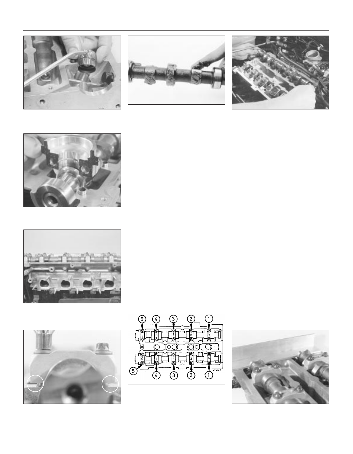
away from the gauge, and note the gauge
reading. If the endfloat measured is found to
be at or beyond the specified service limit, fit
a new camshaft and repeat the check; if the
clearance is still excessive, the cylinder head
must be renewed.
Refitting
17 On reassembly, liberally oil the cylinder
head hydraulic tappet bores and the tappets
(see illustration). Note that if new tappets are
being fitted, they must be charged with clean
engine oil before installation. Carefully refit the
tappets to the cylinder head, ensuring that each
tappet is refitted to its original bore, and is the
correct way up. Some care will be required to
enter the tappets squarely into their bores.
18 Liberally oil the camshaft bearings and
lobes (see illustration). Ensuring that each
camshaft is in its original location, refit the
camshafts, locating each so that the slot in its
left-hand end is approximately parallel to, and
just above, the cylinder head mating surface
(see illustration).
19 Ensure that the locating dowels are
pressed firmly into their recesses, and check
that all mating surfaces are completely clean,
unmarked and free from oil. Apply a thin film
of suitable sealant (Ford recommend Loctite
518) to the mating surfaces of each
camshaft’s right-hand bearing cap (see
illustration). Referring to paragraph 6 of
Section 12, some owners may wish to fit the
new camshaft oil seals at this stage.
20 All camshaft bearing caps have a singledigit identifying number etched on them (see
illustration). The exhaust camshaft’s bearing
caps are numbered in sequence 0 (right-hand
cap) to 4 (left-hand cap), the inlet’s 5 (righthand cap) to 9 (left-hand cap); see illustration
13.21B for details. Each cap is to be fitted so
that its numbered side faces outwards, to the
front (exhaust) or to the rear (inlet).
21 Ensuring that each cap is kept square to
the cylinder head as it is tightened down, and
working in the sequence shown, tighten the
camshaft bearing cap bolts slowly and by one
turn at a time, until each cap touches the
cylinder head (see illustrations). Next, go
round again in the same sequence, tightening
the bolts to the first stage torque wrench
setting specified, then once more, tightening
them to the second stage setting. Work only
as described, to impose gradually and evenly
the pressure of the valve springs on the caps.
Fit the camshaft aligning tool; it should slip
into place as described in paragraph 10 of
Section 10 (see illustration).
22 Wipe off all surplus sealant, so that none
is left to find its way into any oilways. Follow
the sealant manufacturer’s instructions as to
the time needed for curing; usually, at least an
hour must be allowed between application of
the sealant and starting the engine.
2A•16 In-car engine repair procedures
13.17 Oil liberally when refitting hydraulic
tappets
13.18A Apply engine assembly lubricant or
molybdenum disulphide-based grease to
the cam lobes and journals before refitting
a camshaft
13.19 Apply sealant to mating surface of
camshaft right-hand bearing caps
13.20 Etched marks on camshaft bearing
caps must be arranged as shown, and face
outwards
13.18B Use camshaft position sensor lobe
to identify inlet camshaft on refitting locate camshafts as described in text
13.21A Keep caps square to cylinder head
at all times when tightening down
13.21B Camshaft bearing cap tightening
sequence
Note: View from front of vehicle - locate
bearing caps according to etched numbers,
aligned as described in text
13.21C Fit camshaft aligning tool to set
TDC position . . .
Page 57
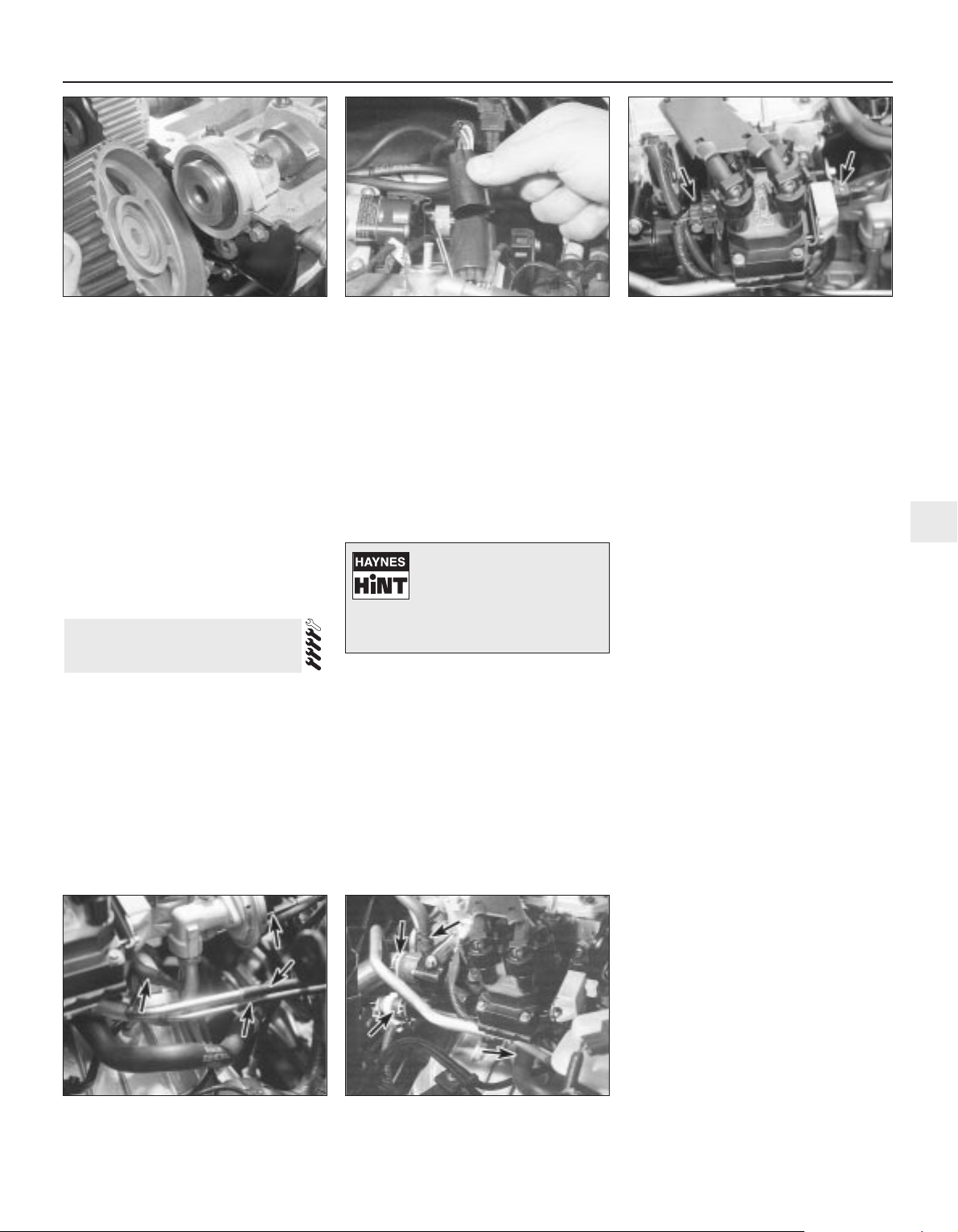
23 If using Ford’s recommended procedure,
fit new oil seals to the camshafts as
described in paragraph 5 of Section 12.
24 Using the marks and notes made on
dismantling to ensure that each is refitted to
its original camshaft, refit the toothed pulleys
to the camshafts, tightening the retaining
bolts loosely (see illustration). Slip the timing
belt back onto the pulleys (refer to paragraph 21 of Section 10) and tighten the bolts
securely - use the forked holding tool
described in paragraph 18 of Section 10.
25 The remainder of the reassembly
procedure, including checking the camshaft
alignment (valve timing) and setting the timing
belt tension, is as described in paragraphs 17
to 27 of Section 10.
Removal
Note: The following text assumes that the
cylinder head will be removed with both inlet
and exhaust manifolds attached; this
simplifies the procedure, but makes it a bulky
and heavy assembly to handle - an engine
hoist will be required, to prevent the risk of
injury, and to prevent damage to any delicate
components as the assembly is removed and
refitted. If it is wished first to remove the
manifolds, proceed as described in Sections
6 and 7 of this Chapter; amend the following
procedure accordingly.
1 Relieve the fuel system pressure (see
Chapter 4).
2 With the vehicle parked on firm level
ground, open the bonnet and disconnect the
battery negative (earth) lead - see Chapter 5,
Section 1.
3 Whenever you disconnect any vacuum
lines, coolant and emissions hoses, wiring
loom connectors, earth straps and fuel lines
as part of the following procedure, always
label them clearly, so that they can be
correctly reassembled.
4 Unplugging the two electrical connectors,
disconnecting the vacuum hose (where fitted)
and disconnecting the crankcase breather
hose from the cylinder head cover, remove
the complete air cleaner assembly with the air
mass meter, the resonator and the plenum
chamber (see Chapter 4).
5 Equalise the pressure in the fuel tank by
removing the filler cap, then undo the fuel
feed and return lines connecting the engine to
the chassis (see Chapter 4). Plug or cap all
open fittings.
6 Disconnect the accelerator cable from the
throttle linkage as described in Chapter 4 -
where fitted, disconnect also the cruise control
actuator cable (see Chapter 12). Secure the
cable(s) clear of the engine/transmission.
7 Unbolt the power steering high-pressure
pipe from the cylinder head rear support
plate/engine lifting eye, and from the front
support plate/pump bracket. Releasing its
wire clip, unplug the power steering pressure
switch electrical connector, then unbolt the
earth lead from the cylinder head rear support
plate/engine lifting eye.
8 Remove the three screws securing the
wiring “rail” to the rear of the manifold.
Releasing its wire clip, unplug the large
electrical connector (next to the fuel pressure
regulator) to disconnect the engine wiring from
the main loom (see illustration). Unplug the
electrical connectors on each side of the
ignition coil, and the single connector from
beneath the front of the thermostat housing, to
disconnect the coil and coolant temperature
gauge sender wiring (see illustration).
9 Marking or labelling them as they are
unplugged, disconnect the vacuum hoses as
follows:
(a) One from the rear of the throttle housing
(only the one hose - there is no need to
disconnect the second hose running to
the fuel pressure regulator).
(b) One from the union on the inlet manifold’s
left-hand end (see illustration).
(c) The braking system vacuum servo unit
hose (see Chapter 9 for details).
(d) Disconnect all vacuum hoses from the
Exhaust Gas Recirculation system
components - one from the EGR valve
and two from the EGR pipe. (Note that
these last two are of different sizes, as are
their pipe stubs, so that they can only be
connected the correct way round.)
10 Unbolt both parts of the exhaust manifold
heat shield; unclip the coolant hose to allow the
upper part to be withdrawn. Either remove the
dipstick and tube, or swing them out of the way.
11 Unscrew the single bolt securing the
pulse-air filter housing to the engine/
transmission front mounting bracket, then
disconnect its vacuum hose.
12 Drain the cooling system (see Chapter 1).
13 Disconnect all coolant hoses from the
thermostat housing (see illustration).
14 Cylinder head -
removal and refitting
In-car engine repair procedures 2A•17
2A
14.9 Disconnect vacuum hoses (arrowed)
as described in text
14.13 Disconnect all coolant hoses
(arrowed) from thermostat housing
13.24 . . . while camshaft toothed pulleys
are refitted
14.8A Release wire clip to unplug engine
wiring loom connector from inlet manifold
14.8B Unplug connectors (arrowed) to
disconnect ignition coil wiring
Masking tape and/or a touchup paint applicator work
well for marking items.
Take instant photos, or
sketch the locations of components
and brackets.
Page 58
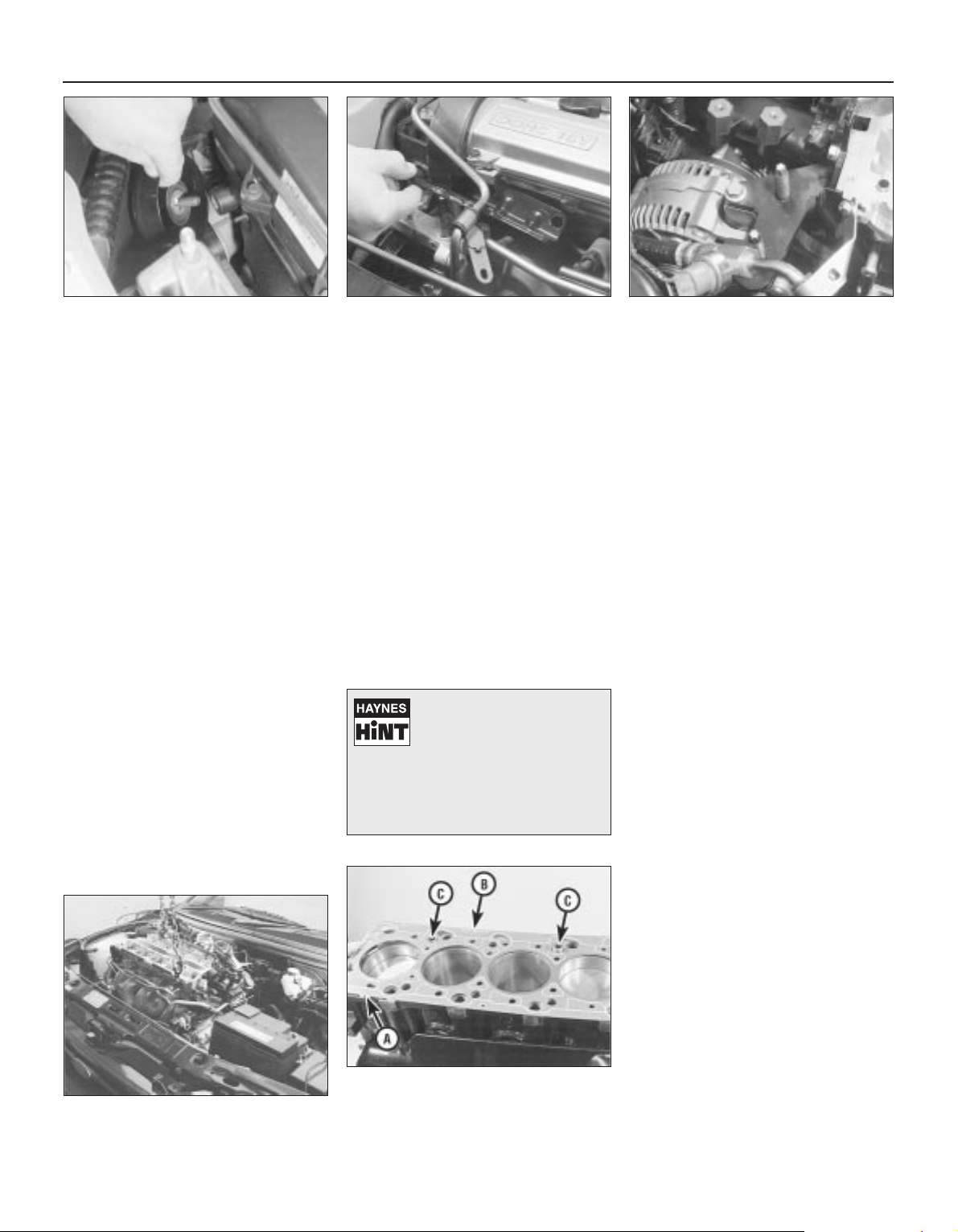
14 Unscrew the two nuts to disconnect the
exhaust system front downpipe from the
manifold (Chapter 4); disconnect the oxygen
sensor wiring, so that it is not strained by the
weight of the exhaust system.
15 Remove the auxiliary drivebelt (see
Chapter 1).
16 Support the weight of the
engine/transmission using a trolley jack, with
a wooden spacer to prevent damage to the
sump.
17 Unscrew the six nuts securing the
engine/transmission right-hand mounting
bracket, then withdraw the bracket. Unbolt
the auxiliary drivebelt’s idler pulley (see
illustration).
18 Unbolt the cylinder head front and rear
support plates (see illustrations).
19 Remove the timing belt and both
camshafts (see Sections 10 and 13); if the
cylinder head is to be dismantled, withdraw
the hydraulic tappets.
20 Remove the timing belt inner shield (see
Section 9).
21 Working in the reverse of the sequence
shown in illustration 14.32C, slacken the ten
cylinder head bolts progressively and by one
turn at a time; a Torx key (TX 55 size) will be
required. Remove each bolt in turn, and
ensure that new replacements are obtained
for reassembly; these bolts are subjected to
severe stresses and so must be renewed,
regardless of their apparent condition,
whenever they are disturbed.
22 Lift the cylinder head away; use
assistance if possible, as it is a heavy
assembly (see illustration). Remove the
gasket, noting the two dowels, and discard it.
Refitting
23 The mating faces of the cylinder head and
cylinder block must be perfectly clean before
refitting the head. Use a hard plastic or wood
scraper to remove all traces of gasket and
carbon; also clean the piston crowns. Take
particular care, as the soft aluminium alloy is
easily damaged. Also, make sure that the
carbon is not allowed to enter the oil and
water passages - this is particularly important
for the lubrication system, as carbon could
block the oil supply to any of the engine’s
components. Using adhesive tape and paper,
seal the water, oil and bolt holes in the
cylinder block. Clean all the pistons in the
same way.
24 Check the mating surfaces of the cylinder
block and the cylinder head for nicks, deep
scratches and other damage. If slight, they
may be removed carefully with a file, but if
excessive, machining may be the only
alternative to renewal.
25 If warpage of the cylinder head gasket
surface is suspected, use a straight edge to
check it for distortion. Refer to Part B of this
Chapter, Section 7, if necessary.
26 Wipe clean the mating surfaces of the
cylinder head and cylinder block. Check that
the two locating dowels are in position in the
cylinder block, and that all cylinder head bolt
holes are free from oil.
27 Position a new gasket over the dowels on
the cylinder block surface, so that the
“TOP/OBEN” mark is uppermost, and the
tooth (or teeth, according to engine size)
protruding from one edge point to the front of
the vehicle (see illustration).
28 Temporarily refit the crankshaft pulley,
and rotate the crankshaft anti-clockwise so
that No 1 cylinder’s piston is lowered to
approximately 20 mm before TDC, thus
avoiding any risk of valve/piston contact and
damage during reassembly.
29 As the cylinder head is such a heavy and
awkward assembly to refit with manifolds, it is
helpful to make up a pair of guide studs from
two 10 mm (thread size) studs approximately
90 mm long, with a screwdriver slot cut in one
end - two old cylinder head bolts with their
heads cut off would make a good starting
point. Screw these guide studs, screwdriver
slot upwards to permit removal, into the bolt
holes at diagonally-opposite corners of the
cylinder block surface (or into those where
the locating dowels are fitted, as shown);
ensure that approximately 70 mm of stud
protrudes above the gasket.
30 Refit the cylinder head, sliding it down the
guide studs (if used) and locating it on the
dowels (see illustration). Unscrew the guide
studs (if used) when the head is in place.
31 Fit the new cylinder head bolts dry (do not
oil their threads); carefully enter each into its
hole and screw it in, by hand only, until fingertight.
32 Working progressively and in the
sequence shown, use first a torque wrench,
2A•18 In-car engine repair procedures
14.17 Unbolt auxiliary drivebelt idler pulley 14 18A Remove cylinder head front . . . 14.18B . . . and rear support plates
14.22 Using an engine hoist to lift off the
cylinder head complete with manifolds
14.27 Ensuring protruding tooth (or teeth)
“A” are at front and marking “B” is
upwards, locate new cylinder head gasket
on dowels “C”
To prevent carbon entering
the gap between the pistons
and bores, smear a little
grease in the gap. After
cleaning each piston, use a small brush
to remove all traces of grease and
carbon from the gap, then wipe away
the remainder with a clean rag.
Page 59
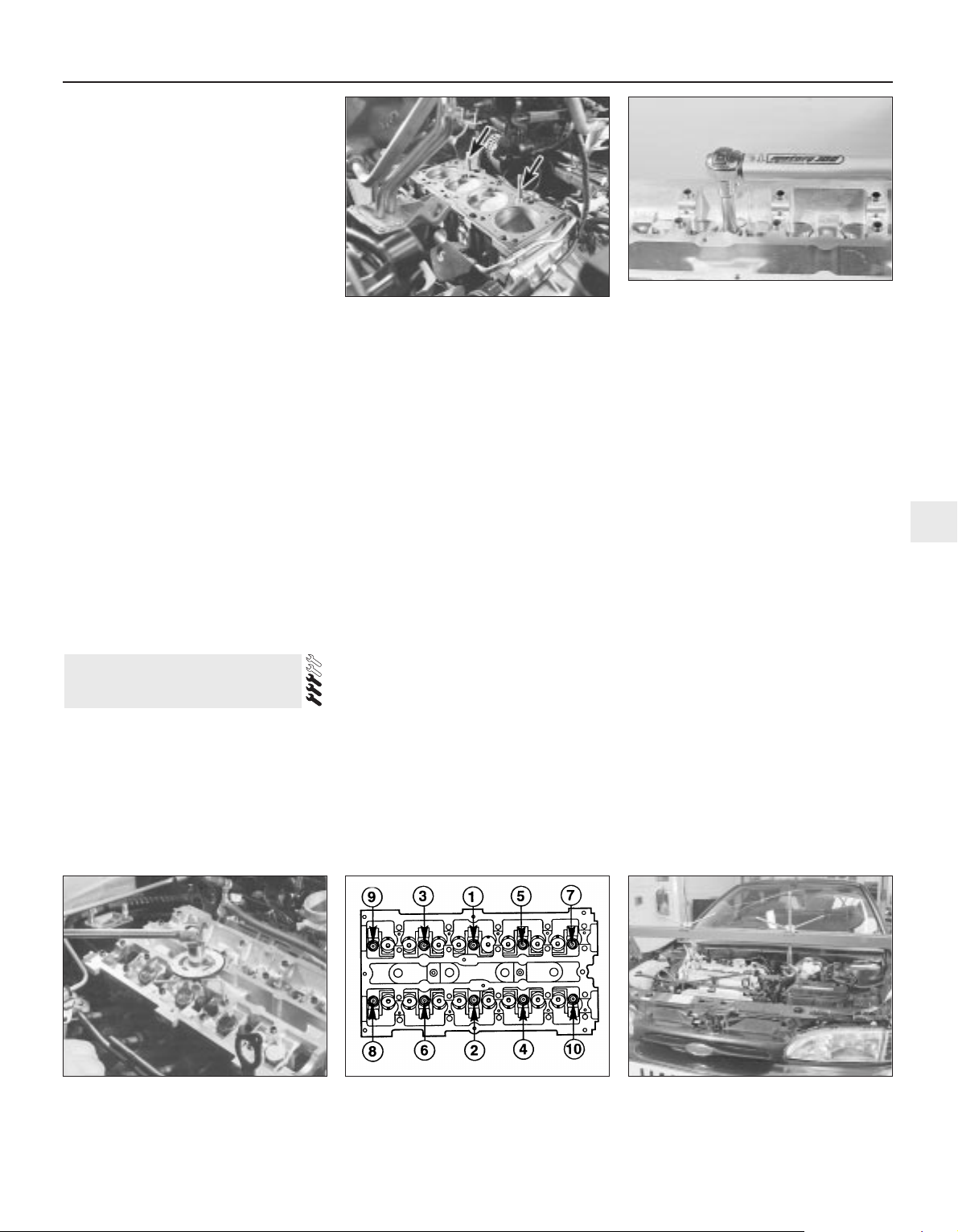
then an ordinary socket extension bar and an
angle gauge, to tighten the cylinder head
bolts in the stages given in the Specifications
Section of this Chapter (see illustrations).
Note: Once tightened correctly, following this
procedure, the cylinder head bolts do not
require check-tightening, and must not be retorqued.
33 Refit the hydraulic tappets (if removed),
the camshafts, their oil seals and pulleys (see
Sections 10, 11, 12 and 13, as appropriate).
Temporarily refit the crankshaft pulley, and
rotate the crankshaft clockwise to return the
pulley notches to the position described in
paragraph 8 of Section 10.
34 Refit the timing belt and covers, checking
the camshaft alignment (valve timing) and
setting the timing belt tension, as described in
Section 10.
35 The remainder of reassembly is the
reverse of the removal procedure, noting the
following points:
(a) Tighten all fasteners to the torque wrench
settings specified.
(b) When reassembling the
engine/transmission right-hand mounting,
renew the self-locking nuts, and do not
allow the mounting to twist as the middle
two of the bracket’s six nuts are
tightened.
(c) Refill the cooling system, and top-up the
engine oil.
(d) Check all disturbed joints for signs of oil
or coolant leakage, once the engine has
been restarted and warmed-up to normal
operating temperature.
Removal
Note: To carry out this task with the
engine/transmission installed in the vehicle
requires the assistance of at least one person,
plus the equipment necessary to raise and
support the front of the vehicle (high enough
that the sump can be withdrawn from
underneath), and to lift and support the
complete engine/transmission unit 2 to
3 inches from its mountings while the vehicle
is raised. Precise details of the procedure will
depend on the equipment available - the
following is typical.
The full procedure outlined below must be
followed, so that the mating surfaces can be
cleaned and prepared to achieve an oil-tight
joint on reassembly, and so that the sump
can be aligned correctly; depending on your
skill and experience, and the tools and
facilities available, it may be that this task can
be carried out only with the engine removed
from the vehicle.
Note that the sump gasket must be
renewed whenever it is disturbed.
1 With the vehicle parked on firm level
ground, open the bonnet and disconnect the
battery negative (earth) lead - see Chapter 5,
Section 1.
2 Drain the engine oil, then clean and refit the
engine oil drain plug, tightening it to the
specified torque wrench setting. Although not
strictly necessary as part of the dismantling
procedure, owners are advised to remove
and discard the oil filter, so that it can be
renewed with the oil (see Chapter 1).
3 Drain the cooling system (see Chapter 1).
4 Disconnect the radiator bottom hose from
the radiator union and from the (heater)
coolant pipe. Unbolt the coolant pipe from
the sump; if they will prevent sump removal,
disconnect or release the coolant hoses from
the oil cooler unions (where fitted).
5 Unscrew the two bolts securing the power
steering system pipes to the right-hand side
of the subframe.
6 Unplug the electrical connector(s) to
disconnect the oxygen sensor and, where
fitted, the oil level sensor wiring - unclip the
connectors to release the wiring where
necessary.
7 Where the vehicle is fitted with automatic
transmission, trace the fluid cooler lines from
the transmission to the radiator, and release
them from any clips etc, so that they have as
much movement as possible.
8 Remove the auxiliary drivebelt cover (see
Chapter 1).
9 Unscrew the nuts to disconnect the
exhaust system front downpipe from the
manifold, then either unhook all the system’s
rubber mountings and withdraw the complete
exhaust system from under the vehicle, or
remove only the downpipe/catalytic converter
(see Chapter 4 for details).
10 Unscrew the sump-to-transmission bolts,
also any securing the engine/transmission
lower adaptor plate.
11 Unplugging the two electrical connectors,
disconnecting the vacuum hose (where fitted)
and disconnecting the crankcase breather
hose from the cylinder head cover, remove
the complete air cleaner assembly with the air
mass meter, the resonator and the plenum
chamber (see Chapter 4).
12 Take the weight of the engine/
transmission unit using the lifting eyes
provided on the cylinder head; bolt on
15 Sump - removal and refitting
In-car engine repair procedures 2A•19
2A
14.32B . . . and to third stage using angle
gauge
14.32C Cylinder head bolt tightening
sequence
Note: View from rear of vehicle
15.12 Equipment must be available to raise
and support engine/transmission unit while
vehicle is raised, to allow sump removal
14.30 Refitting cylinder head - note
fabricated guide studs (arrowed)
14.32A Tightening cylinder head bolts (to
first and second stages) using torque
wrench . . .
Page 60
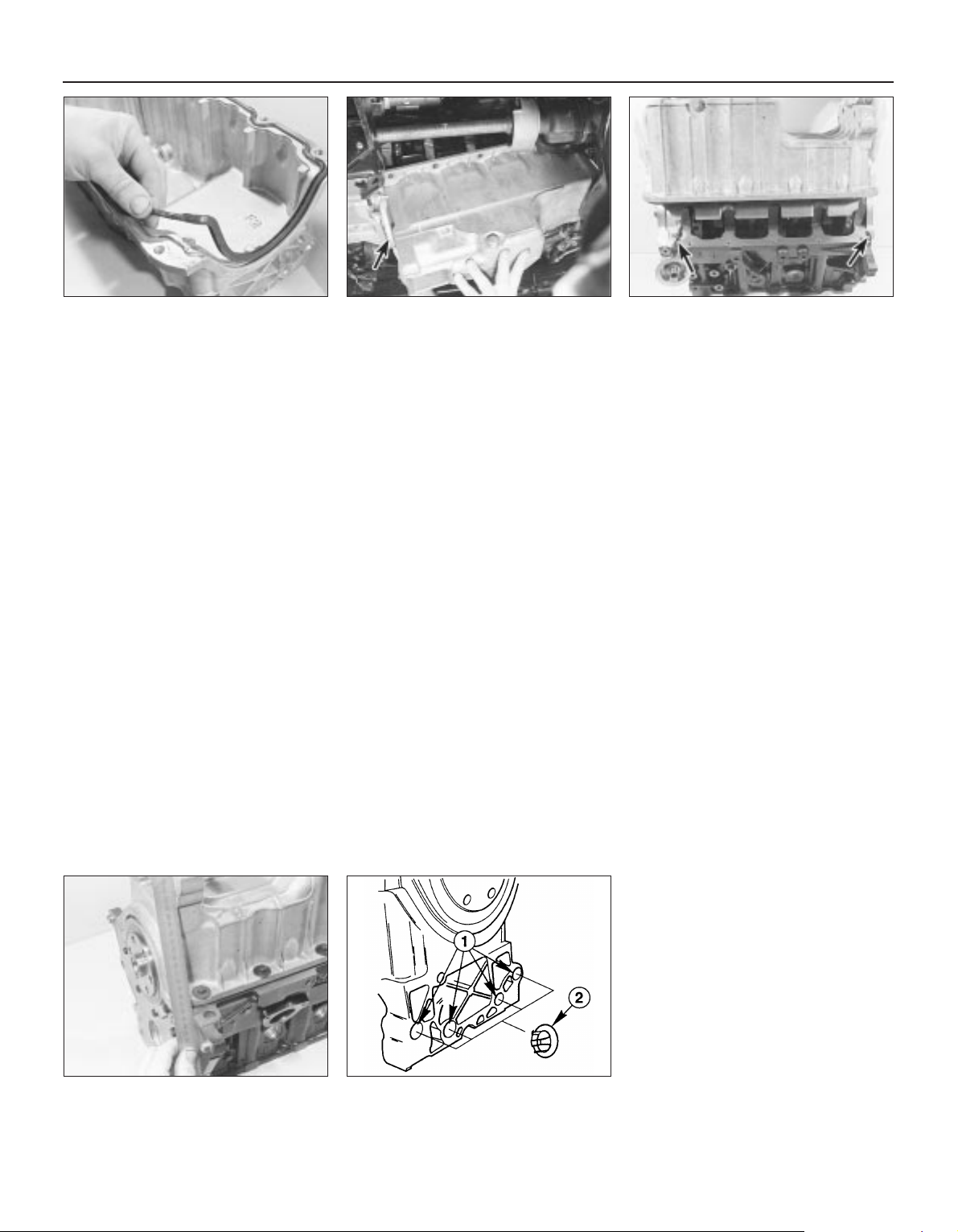
additional lifting eyes where required (see
illustration). Remove completely the
engine/transmission front mounting, unscrew
the rear mounting’s centre bolt, and unbolt
the left-hand mounting from the body.
Unscrew the six nuts securing the right-hand
mounting bracket, and withdraw the bracket.
13 Being careful to watch the wiring, coolant
hoses, fluid cooler pipes or gearchange
linkage and transmission support rods (where
appropriate), and the radiator electric cooling
fan, to ensure that nothing is trapped,
stretched or damaged, lift the
engine/transmission unit by 2 to 3 inches and
support it securely.
14 Progressively unscrew the sump retaining
bolts. Break the joint by striking the sump
with the palm of the hand, then lower the
sump and withdraw it with the
engine/transmission lower adaptor plate; note
the presence of any shims between the sump
and transmission.
15 Remove and discard the sump gasket;
this must be renewed as a matter of course
whenever it is disturbed.
16 While the sump is removed, take the
opportunity to remove the oil pump pick-up/
strainer pipe and to clean it (see Section 16).
Refitting
17 On reassembly, thoroughly clean and
degrease the mating surfaces of the cylinder
block/crankcase and sump, then use a clean
rag to wipe out the sump and the engine’s
interior. If the oil pump pick-up/strainer pipe
was removed, fit a new gasket and refit the
pipe, tightening its screws to the specified
torque wrench setting. Fit the new gasket to
the sump mating surface so that the gasket
fits into the sump groove (see illustration).
18 If the sump is being refitted with the
engine/transmission still connected and in the
vehicle, proceed as follows:
(a) Check that the mating surfaces of the
sump, the cylinder block/crankcase and
the transmission are absolutely clean and
flat. Any shims found on removal of the
sump must be refitted in their original
locations.
(b) Apply a thin film of suitable sealant (Ford
recommend Hylosil 102) to the junctions
of the cylinder block/crankcase with the
oil pump and the crankshaft left-hand oil
seal carrier. Without delay - the sump
bolts must be fully tightened within 10 to
20 minutes of applying the sealant - offer
up the sump and engine/transmission
lower adaptor plate, and refit the bolts,
tightening them lightly at first (see
illustration).
(c) Ensuring that the engine/transmission
lower adaptor plate is correctly located,
firmly press the sump against the
transmission, and tighten the
transmission-to-sump (ie, engine) bolts to
the specified torque wrench setting.
(d) Without disturbing the position of the
sump, and working in a diagonal
sequence from the centre outwards,
tighten the sump bolts to the specified
torque wrench setting.
(e) Proceed to paragraph 20.
19 If the sump is being refitted with the
engine and transmission separated (in or out
of the vehicle), proceed as follows:
(a) Apply a thin film of suitable sealant (Ford
recommend Hylosil 102) to the junctions
of the cylinder block/crankcase with the
oil pump and the crankshaft left-hand oil
seal carrier (see illustration). Without
delay - the sump bolts must be fully
tightened within 10 to 20 minutes of
applying the sealant - offer up the sump
to the cylinder block/crankcase, and
insert the sump bolts, tightening them
lightly at first.
(b) Using a suitable straight edge to check
alignment across the flat-machined faces
of each, move the sump as necessary so
that its left-hand face - including any
shims found on removal - is flush with
that of the cylinder block/crankcase (see
illustration). Without disturbing the
position of the sump, and working in a
diagonal sequence from the centre
outwards, tighten the sump bolts to the
specified torque wrench setting.
(c) Check again that both faces are flush
before proceeding; if necessary, unbolt
the sump again, clean the mating
surfaces, and repeat the full procedure to
ensure that the sump is correctly aligned.
(d) If it is not possible to achieve exact
alignment by moving the sump, shims are
available in thicknesses of 0.25 mm
(colour-coded yellow) or 0.50 mm (colourcoded black) to eliminate the discrepancy
(see illustration).
20 The remainder of reassembly is the
reverse of the removal procedure, noting the
following points.
(a) Tighten all fasteners to the torque wrench
settings specified.
(b) Always renew any self-locking nuts
disturbed on removal.
(c) Lower the engine/transmission unit into
place, and reassemble the rear, left-hand
2A•20 In-car engine repair procedures
15.17 Ensure gasket is located correctly in
sump groove
15.18 Engine/transmission lower adaptor
plate (arrowed) must be refitted with sump
15.19A Apply sealant (arrowed) as
directed when refitting sump
15.19B Checking alignment of sump with
cylinder block/crankcase
15.19C Sump-to-cylinder block/crankcase
alignment shims
1 Fitting points on sump 2 Shim
Page 61
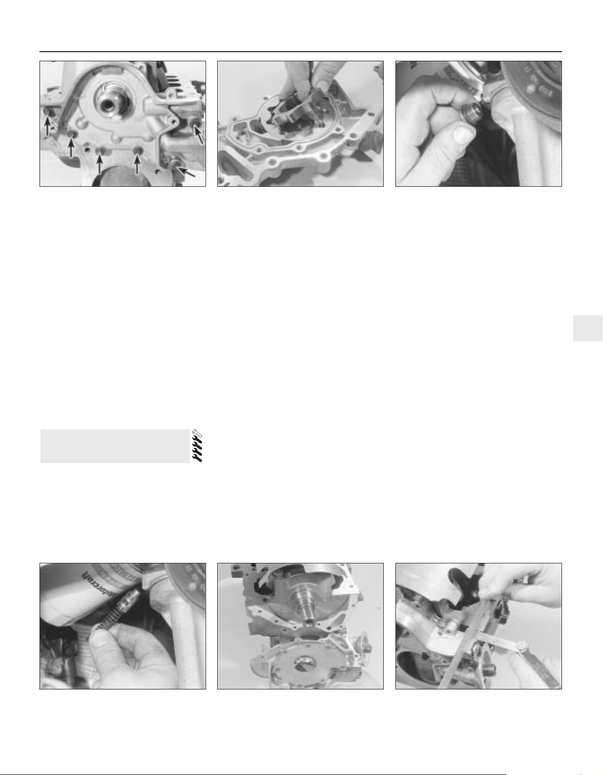
and right-hand mountings. Do not yet
release the hoist; the weight of the
engine/transmission unit must not be
taken by the mountings until all are
correctly aligned.
(d) Fitting the Ford service tool in place of the
front mounting, tighten the
engine/transmission mounting fasteners
to their specified torque wrench settings,
and in the sequence described in Part B
of this Chapter, Section 4, paragraphs 49
and 50.
(e) Refill the cooling system (see Chapter 1).
(f) Refill the engine with oil, remembering
that you are advised to fit a new filter (see
Chapter 1).
(g) Check for signs of oil or coolant leaks
once the engine has been restarted and
warmed-up to normal operating
temperature.
Removal
Note: While this task is theoretically possible
when the engine is in place in the vehicle, in
practice, it requires so much preliminary
dismantling, and is so difficult to carry out due
to the restricted access, that owners are
advised to remove the engine from the vehicle
first. Note, however, that the oil pump
pressure relief valve can be removed with the
engine in situ - see paragraph 8.
In addition to the new pump gasket and
other replacement parts required, read
through Section 15, and ensure that the
necessary tools and facilities are available.
1 Remove the timing belt (see Section 10).
2 Withdraw the crankshaft toothed pulley
and the thrustwasher behind it, noting which
way round the thrustwasher is fitted (see
Section 11).
3 Remove the sump (see Section 15).
4 Undo the screws securing the oil pump
pick-up/strainer pipe to the pump, then
unscrew the nut and withdraw the oil pump
pick-up/strainer pipe. Discard the gasket.
5 Unbolt the pump from the cylinder
block/crankcase (see illustration). Withdraw
and discard the gasket, and remove the
crankshaft right-hand oil seal. Thoroughly
clean and degrease all components,
particularly the mating surfaces of the pump,
the sump, and the cylinder block/crankcase.
Inspection
6 Unscrew the Torx screws, and remove the
pump cover plate; noting any identification
marks on the rotors, withdraw the rotors (see
illustration).
7 Inspect the rotors for obvious signs of wear
or damage, and renew if necessary; if either
rotor, the pump body, or its cover plate are
scored or damaged, the complete oil pump
assembly must be renewed.
8 The oil pressure relief valve can be
dismantled, if required, without disturbing the
pump. With the vehicle parked on firm level
ground, apply the handbrake securely and
raise its front end, supporting it securely on
axle stands. Remove the front right-hand
roadwheel and auxiliary drivebelt cover (see
Chapter 1) to provide access to the valve.
9 Unscrew the threaded plug, and recover
the valve spring and plunger (see
illustrations). If the plug’s sealing O-ring is
worn or damaged, a new one must be
obtained, to be fitted on reassembly.
10 Reassembly is the reverse of the
dismantling procedure; ensure the spring and
valve are refitted the correct way round, and
tighten the threaded plug securely.
Refitting
11 The oil pump must be primed on
installation, by pouring clean engine oil into it,
and rotating its inner rotor a few turns.
12 Using grease to stick the new gasket in
place on the cylinder block/crankcase, and
rotating the pump’s inner rotor to align with
the flats on the crankshaft, refit the pump and
insert the bolts, tightening them lightly at first
(see illustration).
13 Using a suitable straight edge and feeler
gauges, check that the pump is both centred
exactly around the crankshaft, and aligned
squarely so that its (sump) mating surface is
exactly the same amount - between 0.3 and
0.8 mm - below that of the cylinder block/
crankcase on each side of the crankshaft
(see illustration). Being careful not to disturb
16 Oil pump - removal,
inspection and refitting
In-car engine repair procedures 2A•21
2A
16.9B . . . to withdraw oil pressure relief
valve spring and plunger
16.12 Use new gasket when refitting oil
pump
16.13 Check the oil pump is positioned
correctly
16.5 Unscrew bolts (arrowed) to remove
oil pump
16.6 Withdrawing oil pump inner rotor 16.9A Unscrew threaded plug - seen
through right-hand wheel arch . . .
Page 62
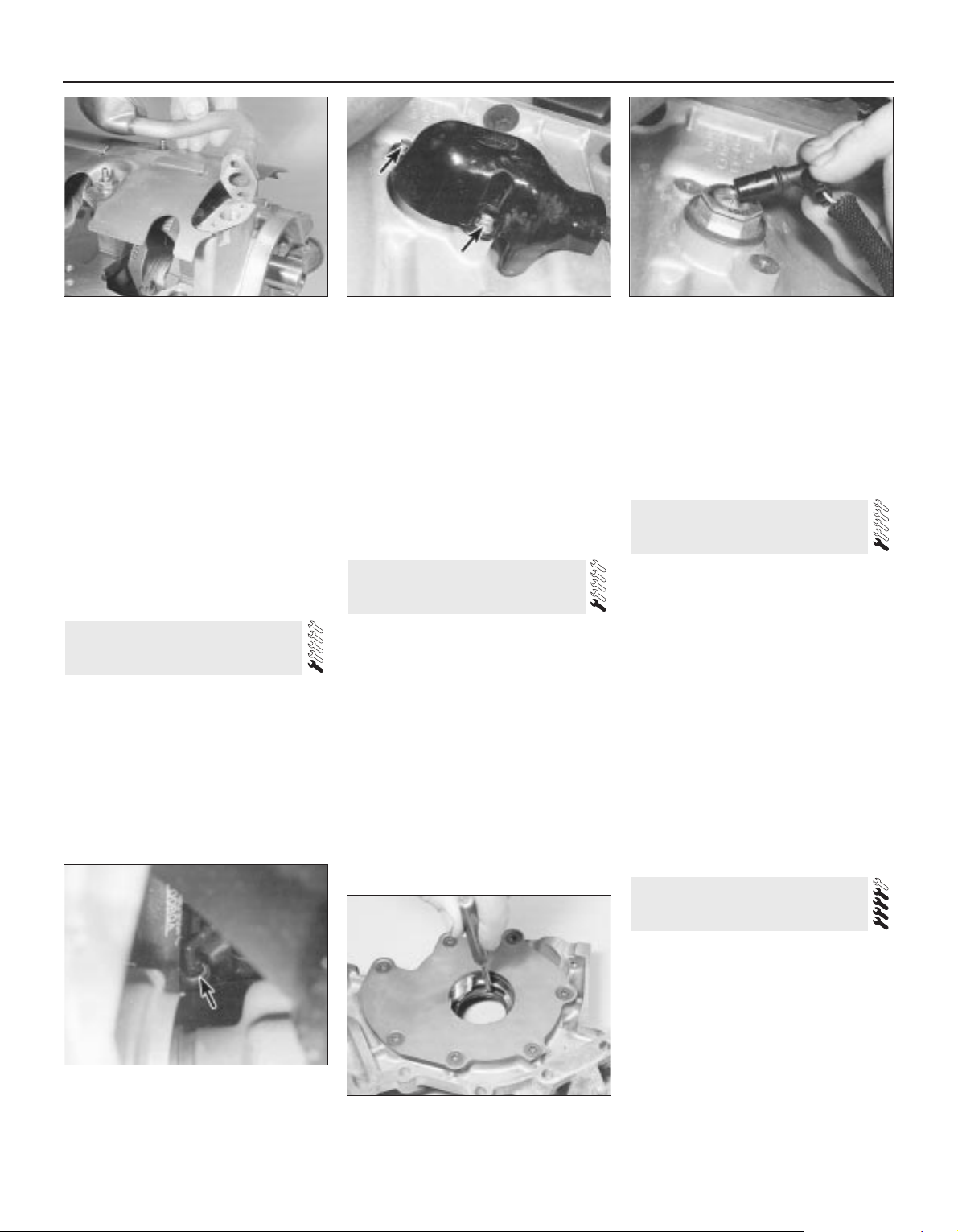
the gasket, move the pump into the correct
position, and tighten its bolts to the specified
torque wrench setting.
14 Check that the pump is correctly located;
if necessary, unbolt it again, and repeat the
full procedure to ensure that the pump is
correctly aligned.
15 Fit a new crankshaft right-hand oil seal
(see Section 20).
16 Using grease to stick the gasket in place
on the pump, refit the pick-up/strainer pipe,
tightening its screws and nut to their specified
torque wrench settings (see illustration).
17 The remainder of reassembly is the
reverse of the removal procedure, referring to
the relevant text for details where required.
1 Drain the cooling system (see Chapter 1).
Disconnect the coolant hoses from the oil
cooler.
2 Unscrew the oil filter (see Chapter 1) catch any escaping oil in a drip tray.
3 Unscrew the filter adaptor from the oil
pump, and withdraw the oil cooler; note how
its unions are aligned, and be prepared for oil
loss from the cooler.
4 Refitting is the reverse of the removal
procedure, noting the following points:
(a) Renew all O-rings and seals disturbed on
removal.
(b) Align the cooler’s unions as noted on
removal, and tighten the adaptor to the
specified torque wrench setting.
(c) Refill the cooling system (see Chapter 1).
(d) Refit the oil filter, then check the engine
oil level, and top-up as necessary (see
Chapter 1).
(e) Check for signs of oil or coolant leaks once
the engine has been restarted and warmed-
up to normal operating temperature.
1 With the vehicle parked on firm level
ground, open the bonnet and disconnect the
battery negative (earth) lead - see Chapter 5,
Section 1.
2 Raise the front of the vehicle, and support it
securely on axle stands.
3 Undo the two screws, and remove the
sensor’s cover from the front of the sump
(see illustration).
4 Unplug the wiring from the sensor (see
illustration). Where necessary, unplug the
electrical connector to disconnect the sensor
wiring, and unclip the connector to release
the wiring from the vehicle.
5 Unscrew the sensor, and quickly plug the
sump aperture to minimise oil loss; note the
sensor’s seal.
6 Refitting is the reverse of the removal
procedure; renew the sensor’s seal if it is
worn or damaged, and tighten the sensor to
the specified torque wrench setting. Check
the engine oil level, and top-up as necessary
(see Chapter 1) - check for signs of oil leaks
once the engine has been restarted and
warmed-up to normal operating temperature.
1 The switch is screwed into the rear of the
cylinder block, above the right-hand
driveshaft’s support bearing (see
illustration).
2 With the vehicle parked on firm level
ground, open the bonnet and disconnect the
battery negative (earth) lead - see Chapter 5,
Section 1.
3 Raise the front of the vehicle, and support it
securely on axle stands.
4 Unplug the wiring from the switch, and
unscrew it; be prepared for some oil loss.
5 Refitting is the reverse of the removal
procedure; apply a thin smear of suitable
sealant to the switch threads, and tighten it to
the specified torque wrench setting. Check
the engine oil level, and top-up as necessary
(see Chapter 1). Check for signs of oil leaks
once the engine has been restarted and
warmed-up to normal operating temperature.
Note: Don’t try to prise these seals out
without removing the oil pump or seal carrier the seals are too soft, and the amount of
space available is too small, for this to be
possible without considerable risk of damage
to the seal housing and/or the crankshaft
journal. Follow exactly the procedure given
below.
Right-hand seal
1 Remove the oil pump (see Section 16).
2 Drive the oil seal out of the pump from
behind (see illustration).
20 Crankshaft oil seals -
renewal
19 Oil pressure warning light
switch - removal and refitting
18 Oil level sensor -
removal and refitting
17 Oil cooler -
removal and refitting
2A•22 In-car engine repair procedures
16.16 Use new gasket when refitting oil
pick-up pipe to pump
18.3 Remove screws (arrowed) to remove
oil level sensor cover . . .
18.4 . . . disconnecting wiring from sensor
19.1 Oil pressure warning light switch
(arrowed) is screwed into rear of cylinder
block, above right-hand driveshaft support
bearing
20.2 Driving out crankshaft right-hand oil
seal
Page 63
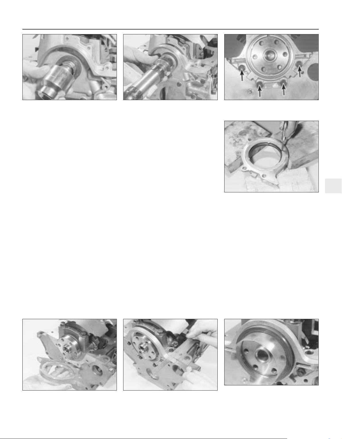
3 Clean the seal housing and crankshaft,
polishing off any burrs or raised edges, which
may have caused the seal to fail in the first
place.
4 Refit the oil pump (see Section 16). Grease
the lips and periphery of the new seal, to ease
installation.
5 To fit a new seal, Ford recommend the use
of their service tool 21-093A, with the
crankshaft pulley bolt, to draw the seal into
place; an alternative can be arranged using a
socket of suitable size, with a washer to
match the crankshaft pulley bolt (see
illustration).
6 If such tools are not available, press the
seal squarely into place by hand; tap it in until
it is flush with the pump housing, using a softfaced mallet and a socket with an outside
diameter only slightly smaller than the seal’s
(see illustration). This approach requires
great care, to ensure that the seal is fitted
squarely, without distortion or damage.
7 Wash off any traces of oil. The remainder of
reassembly is the reverse of the removal
procedure, referring to the relevant text for
details where required. Check for signs of oil
leakage when the engine is restarted.
Left-hand seal
8 Remove the transmission (see the relevant
Part of Chapter 7).
9 Where appropriate, remove the clutch
(Chapter 8).
10 Unbolt the flywheel/driveplate (see
Section 21).
11 Remove the sump (see Section 15).
12 Unbolt the oil seal carrier (see
illustration). Remove and discard its gasket.
13 Supporting the carrier evenly on wooden
blocks, drive the oil seal out of the carrier
from behind (see illustration).
14 Clean the seal housing and crankshaft,
polishing off any burrs or raised edges, which
may have caused the seal to fail in the first
place. Clean also the mating surfaces of the
cylinder block/crankcase and carrier, using a
scraper to remove all traces of the old gasket
- be careful not to scratch or damage the
material of either - then use a suitable solvent
to degrease them.
15 Use grease to stick the new gasket in
place on the cylinder block/crankcase, then
offer up the carrier (see illustration).
16 Using a suitable straight edge and feeler
gauges, check that the carrier is both centred
exactly around the crankshaft, and aligned
squarely so that its (sump) mating surface is
exactly the same amount - between 0.3 and
0.8 mm - below that of the cylinder
block/crankcase on each side of the
crankshaft. Being careful not to disturb the
gasket, move the carrier into the correct
position, and tighten its bolts to the specified
torque wrench setting (see illustration).
17 Check that the carrier is correctly located;
if necessary, unbolt it again, and repeat the
full procedure to ensure that the carrier is
correctly aligned.
18 Ford’s recommended method of seal
fitting is to use service tool 21-141, with two
flywheel bolts to draw the seal into place. If
this is not available, make up a guide from a
thin sheet of plastic or similar, lubricate the
lips of the new seal and the crankshaft
shoulder with grease, then offer up the seal,
with the guide feeding the seal’s lips over the
crankshaft shoulder (see illustration). Press
the seal evenly into its housing by hand only,
and use a soft-faced mallet gently to tap it
into place until it is flush with the surrounding
housing.
19 Wipe off any surplus oil or grease; the
remainder of the reassembly procedure is the
reverse of dismantling, referring to the
relevant text for details where required.
Check for signs of oil leakage when the
engine is restarted.
In-car engine repair procedures 2A•23
2A
20.15 Use new gasket when refitting lefthand oil seal carrier
20.16 Check the oil seal carrier is correctly
positioned
20.18 Using guide made from thin sheet of
plastic to slide oil seal lips over crankshaft
shoulder
20.5 Socket of correct size can be used to
replace Ford service tool, drawing new
seal into place as described
20.6 If seal is tapped into place as shown,
exercise great care to prevent seal from
being damaged or distorted
20.12 Unscrew bolts (arrowed) to remove
crankshaft left-hand oil seal carrier . . .
20.13 . . . and ensure that carrier is
properly supported when driving out used
oil seal - note notches provided in carrier
for drift
Page 64
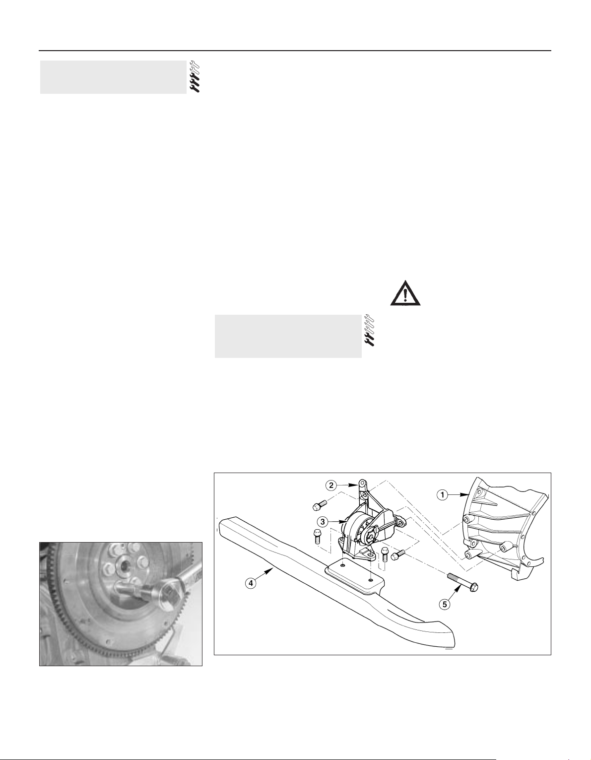
Removal
1 Remove the transmission (see the relevant
Part of Chapter 7). Now is a good time to
check components such as oil seals and
renew them if necessary.
2 Where appropriate, remove the clutch
(Chapter 8). Now is a good time to check or
renew the clutch components and pilot
bearing.
3 Use a centre-punch or paint to make
alignment marks on the flywheel/driveplate
and crankshaft, to ensure correct alignment
during refitting.
4 Prevent the flywheel/driveplate from
turning by locking the ring gear teeth, or by
bolting a strap between the flywheel/
driveplate and the cylinder block/
crankcase. Slacken the bolts evenly until all
are free.
5 Remove each bolt in turn, and ensure that
new replacements are obtained for
reassembly; these bolts are subjected to
severe stresses, and so must be renewed,
regardless of their apparent condition,
whenever they are disturbed.
6 Noting the reinforcing plate (automatic
transmission-equipped models only),
withdraw the flywheel/driveplate; do not drop
it - it is very heavy.
Inspection
7 Clean the flywheel/driveplate to remove
grease and oil. Inspect the surface for cracks,
rivet grooves, burned areas and score marks.
Light scoring can be removed with emery
cloth. Check for cracked and broken ring gear
teeth. Lay the flywheel/driveplate on a flat
surface, and use a straight edge to check for
warpage.
8 Clean and inspect the mating surfaces of
the flywheel/driveplate and the crankshaft. If
the crankshaft left-hand seal is leaking, renew
it (see Section 20) before refitting the
flywheel/driveplate.
9 While the flywheel/driveplate is removed,
clean carefully its inboard (right-hand) face,
particularly the recesses which serve as the
reference points for the crankshaft
speed/position sensor. Clean the sensor’s tip,
and check that the sensor is securely
fastened.
Refitting
10 On refitting, ensure that the
engine/transmission adaptor plate is in place
(where necessary), then fit the
flywheel/driveplate to the crankshaft so that
all bolt holes align - it will fit only one way check this using the marks made on removal.
Do not forget the reinforcing plate (where
fitted).
11 Lock the flywheel/driveplate by the
method used on dismantling. Working in a
diagonal sequence to tighten them evenly,
and increasing to the final amount in two or
three stages, tighten the new bolts to the
specified torque wrench setting (see
illustration).
12 The remainder of reassembly is the
reverse of the removal procedure, referring to
the relevant text for details where required.
General
1 The engine/transmission mountings
seldom require attention, but broken or
deteriorated mountings should be renewed
immediately, or the added strain placed on
the driveline components may cause damage
or wear.
2 While separate mountings may be removed
and refitted individually, if more than one is
disturbed at a time - such as if the
engine/transmission unit is removed from its
mountings - they must be reassembled and
their fasteners tightened in a strict sequence.
3 On reassembly, the weight of the
engine/transmission unit must not be taken
by the mountings until all are correctly
aligned. Fitting the Ford service tool in place
of the front mounting, tighten the
engine/transmission mounting fasteners to
their specified torque wrench settings, and in
the sequence described in Part B of this
Chapter, Section 4, paragraphs 49 and 50.
Inspection
4 During the check, the engine/transmission
unit must be raised slightly, to remove its
weight from the mountings.
5 Raise the front of the vehicle, and support it
securely on axle stands. Position a jack under
the sump, with a large block of wood
between the jack head and the sump, then
carefully raise the engine/transmission just
enough to take the weight off the mountings.
Warning: DO NOT place any part
of your body under the engine
when it is supported only by a
jack!
6 Check the mountings to see if the rubber is
cracked, hardened or separated from the
metal components. Sometimes the rubber
will split right down the centre.
7 Check for relative movement between each
mounting’s brackets and the engine/
transmission or body (use a large screwdriver
or lever to attempt to move the mountings). If
movement is noted, lower the engine and
check-tighten the mounting fasteners.
Renewal
Front mounting
8 Unbolt the resonator support bracket from
the engine compartment front crossmember,
slacken the two clamp screws securing the
22 Engine/transmission
mountings -
inspection and renewal
21 Flywheel/driveplate -
removal, inspection and refitting
2A•24 In-car engine repair procedures
21.11 Note method used to lock
flywheel/driveplate while (new) bolts are
tightened
22.8 Engine/transmission front mounting - manual transmission shown, automatic
equivalent similar
1 Transmission 3 Mounting 5 Mounting centre bolt
2 Mounting bracket 4 Front suspension subframe
Page 65
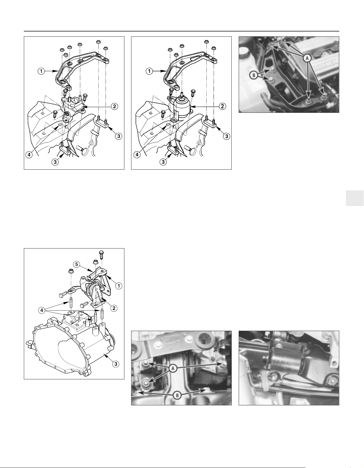
resonator to the air mass meter and plenum
chamber hoses, then swing the resonator up
clear of the thermostat housing (see Chapter
4). Unbolt the pulse-air filter housing from the
mounting bracket, then unfasten the
bolts/nuts securing the mounting to the
subframe, unscrew the centre bolt and
withdraw the mounting; note the location of
the wiring connector bracket. The mounting’s
bracket can be unbolted from the
transmission if required (see illustration).
9 On refitting, ensure that the mounting-totransmission bolts are securely tightened,
then refit the mounting and wiring connector
bracket. Tighten first the mounting-tosubframe bolts/nuts, noting that these are to
be tightened in two stages to the final
specified torque wrench setting. Finally
tighten the mounting’s centre bolt, again to
the specified torque wrench setting.
Right-hand mounting
10 Unscrew the nuts and withdraw the
bracket; note that these nuts are self-locking,
and must therefore be renewed whenever
they are disturbed. Unbolt the mounting from
the body (see illustration).
11 Where hydraulic-type mountings are
fitted - there are only five nuts securing the
bracket, and the mounting is clearly
identifiable from its shape - take care never to
tilt these more than 5° from the vertical (see
illustration).
12 On refitting, renew the self-locking nuts,
and tighten all fasteners to the torque wrench
settings specified. When tightening the nuts,
tighten first the four bracket-to-engine nuts,
then release the hoist or jack to allow the
engine/transmission’s weight to rest on the
mounting. Do not allow the mounting to twist
as the last two of the nuts are tightened (see
illustration).
Left-hand mounting
13 Unplugging the two electrical connectors,
disconnecting the vacuum hose (where fitted)
and disconnecting the crankcase breather
hose from the cylinder head cover, remove
the complete air cleaner assembly with the air
mass meter, the resonator and the plenum
chamber (see Chapter 4).
14 Unscrew the three nuts to release the
mounting from the transmission, then unbolt
it from the body (see illustration). Note that
In-car engine repair procedures 2A•25
2A
22.14 Engine/transmission left-hand
mounting - manual transmission shown,
automatic equivalent similar
1 Mounting bracket
2 Mounting
3 Transmission
4 Studs
5 Fastening plate - where fitted
22.12 When reassembling
engine/transmission right-hand mounting,
tighten nuts “A” first, release lifting
equipment, then tighten remaining
nuts “B” - do not allow mounting to twist
when doing so
22.15 Engine/transmission left-hand
mounting is secured by self-locking nuts
“A” to transmission, by bolts “B” to body
22.16 Where vehicle is fitted with
automatic transmission, additional damper
may be fastened to underside of engine/
transmission rear mounting, as shown
22.10 Engine/transmission right-hand
mounting - standard type
1 Bracket
2 Mounting
3 Brackets bolted to cylinder block/crankcase
4 Vehicle body
22.11 Engine/transmission right-hand
mounting - hydraulic type (where fitted)
1 Bracket
2 Hydraulic mounting
3 Brackets bolted to cylinder block/crankcase
4 Vehicle body
Page 66
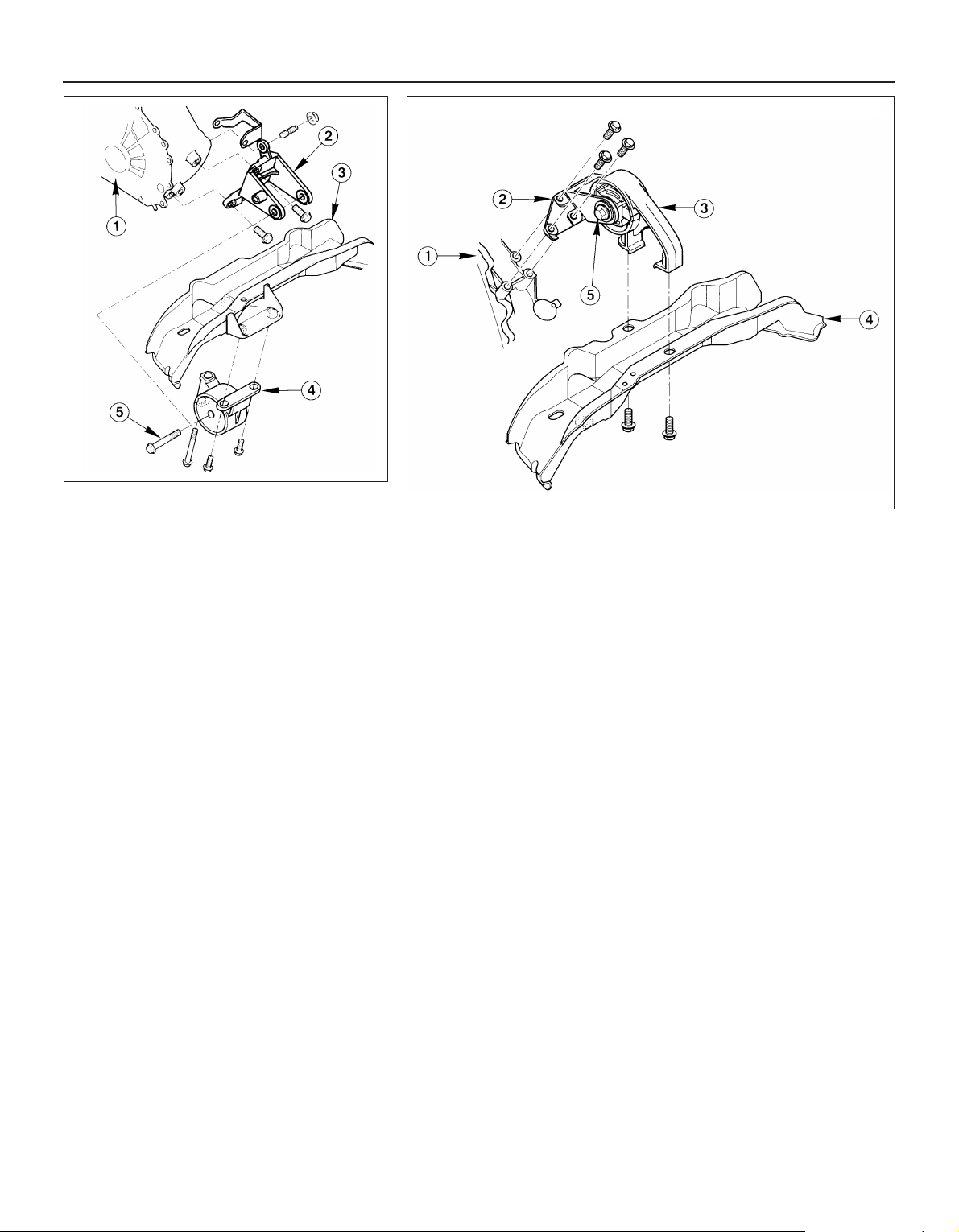
the nuts are self-locking, and must therefore
be renewed whenever they are disturbed.
Unscrew the centre bolt to dismantle the
mounting, if necessary to renew components.
15 On refitting, renew the self-locking nuts,
and do not allow the mounting to twist as the
nuts are tightened (see illustration). Tighten
all fasteners to the specified torque wrench
settings.
Rear mounting
16 Where the vehicle is fitted with automatic
transmission, a separate damper may be
fitted beneath the subframe, which must be
unbolted to reach the mounting’s fasteners
(see illustration).
17 Unbolt the mounting from the subframe,
then unscrew the mounting’s centre bolt. If
required, unbolt the mounting’s bracket from
the transmission (see illustrations).
18 On refitting, ensure that the mounting-totransmission bolts are securely tightened,
then refit the mounting. Tighten first the
mounting-to-subframe bolts, noting that
these are to be tightened in two stages to the
final specified torque wrench setting. Finally
tighten the mounting’s centre bolt, again to
the specified torque wrench setting.
2A•26 In-car engine repair procedures
22.17A Engine/transmission rear mounting manual transmission type
1 Transmission 4 Mounting
2 Mounting bracket 5 Mounting centre bolt
3 Front suspension subframe
22.17B Engine/transmission rear mounting - automatic transmission type
1 Transmission 3 Mounting 5 Mounting centre bolt
2 Mounting bracket 4 Front suspension subframe
Page 67
Chapter 2 Part B: Engine removal
and general engine overhaul procedures
Compression test - description and interpretation . . . See Chapter 2A
Crankshaft - inspection . . . . . . . . . . . . . . . . . . . . . . . . . . . . . . . . . . . 13
Crankshaft - refitting and main bearing running
clearance check . . . . . . . . . . . . . . . . . . . . . . . . . . . . . . . . . . . . . . 17
Crankshaft - removal . . . . . . . . . . . . . . . . . . . . . . . . . . . . . . . . . . . . . 10
Cylinder block/crankcase - cleaning and inspection . . . . . . . . . . . . 11
Cylinder head - dismantling . . . . . . . . . . . . . . . . . . . . . . . . . . . . . . . 6
Cylinder head - reassembly . . . . . . . . . . . . . . . . . . . . . . . . . . . . . . . 8
Cylinder head and valve components - cleaning and inspection . . . 7
Engine - initial start-up after overhaul . . . . . . . . . . . . . . . . . . . . . . . . 19
Engine overhaul - dismantling sequence . . . . . . . . . . . . . . . . . . . . . 5
Engine overhaul - general information . . . . . . . . . . . . . . . . . . . . . . . 2
Engine overhaul - reassembly sequence . . . . . . . . . . . . . . . . . . . . . 15
Engine/transmission - removal and refitting . . . . . . . . . . . . . . . . . . . 4
Engine/transmission removal - methods and precautions . . . . . . . . 3
General information . . . . . . . . . . . . . . . . . . . . . . . . . . . . . . . . . . . . . . 1
Main and big-end bearings - inspection . . . . . . . . . . . . . . . . . . . . . . 14
Piston/connecting rod assemblies - inspection . . . . . . . . . . . . . . . . 12
Piston/connecting rod assemblies - refitting and
big-end bearing running clearance check . . . . . . . . . . . . . . . . . . . 18
Piston/connecting rod assemblies - removal . . . . . . . . . . . . . . . . . . 9
Piston rings - refitting . . . . . . . . . . . . . . . . . . . . . . . . . . . . . . . . . . . . 16
Cylinder head
Maximum permissible gasket surface distortion . . . . . . . . . . . . . . . . . . 0.10 mm
Valve seat included angle . . . . . . . . . . . . . . . . . . . . . . . . . . . . . . . . . . . . 90°
Valve guide bore . . . . . . . . . . . . . . . . . . . . . . . . . . . . . . . . . . . . . . . . . . . 6.060 to 6.091 mm
Valves - general Inlet Exhaust
Valve lift . . . . . . . . . . . . . . . . . . . . . . . . . . . . . . . . . . . . . . . . . . . . . . . . . . 7.500 to 7.685 mm 7.610 to 7.765 mm
Valve length . . . . . . . . . . . . . . . . . . . . . . . . . . . . . . . . . . . . . . . . . . . . . . . 96.870 to 97.330 mm 96.470 to 96.930 mm
Valve head diameter:
1.6 litre engine . . . . . . . . . . . . . . . . . . . . . . . . . . . . . . . . . . . . . . . . . . . 26.0 mm 24.5 mm
1.8 and 2.0 litre engines . . . . . . . . . . . . . . . . . . . . . . . . . . . . . . . . . . . 32.0 mm 28.0 mm
Valve stem diameter . . . . . . . . . . . . . . . . . . . . . . . . . . . . . . . . . . . . . . . . 6.028 to 6.043 mm 6.010 to6.025 mm
Valve stem-to-guide clearance . . . . . . . . . . . . . . . . . . . . . . . . . . . . . . . . 0.017 to 0.064 mm 0.035 to 0.081 mm
Cylinder block
Cylinder bore diameter - 1.6 litre engine:
Class 1 . . . . . . . . . . . . . . . . . . . . . . . . . . . . . . . . . . . . . . . . . . . . . . . . . 76.000 to 76.010 mm
Class 2 . . . . . . . . . . . . . . . . . . . . . . . . . . . . . . . . . . . . . . . . . . . . . . . . . 76.010 to 76.020 mm
Class 3 . . . . . . . . . . . . . . . . . . . . . . . . . . . . . . . . . . . . . . . . . . . . . . . . . 76.020 to 76.030 mm
Cylinder bore diameter - 1.8 litre engine:
Class 1 . . . . . . . . . . . . . . . . . . . . . . . . . . . . . . . . . . . . . . . . . . . . . . . . . 80.600 to 80.610 mm
Class 2 . . . . . . . . . . . . . . . . . . . . . . . . . . . . . . . . . . . . . . . . . . . . . . . . . 80.610 to 80.620 mm
Class 3 . . . . . . . . . . . . . . . . . . . . . . . . . . . . . . . . . . . . . . . . . . . . . . . . . 80.620 to 80.630 mm
Cylinder bore diameter - 2.0 litre engine:
Class 1 . . . . . . . . . . . . . . . . . . . . . . . . . . . . . . . . . . . . . . . . . . . . . . . . . 84.800 to 84.810 mm
Class 2 . . . . . . . . . . . . . . . . . . . . . . . . . . . . . . . . . . . . . . . . . . . . . . . . . 84.810 to 84.820 mm
Class 3 . . . . . . . . . . . . . . . . . . . . . . . . . . . . . . . . . . . . . . . . . . . . . . . . . 84.820 to 84.830 mm
2B•1
Easy, suitable for
novice with little
experience
Fairly easy, suitable
for beginner with
some experience
Fairly difficult, suitable
for competent DIY
mechanic
Difficult, suitable for
experienced DIY
mechanic
Very difficult,
suitable for expert DIY
or professional
Degrees of difficulty
Specifications
Contents
2B
Page 68

Pistons and piston rings
Piston diameter - 1.6 litre engine:
Class 1 . . . . . . . . . . . . . . . . . . . . . . . . . . . . . . . . . . . . . . . . . . . . . . . . . 75.975 to 75.985 mm
Class 2 . . . . . . . . . . . . . . . . . . . . . . . . . . . . . . . . . . . . . . . . . . . . . . . . . 75.985 to 75.995 mm
Class 3 . . . . . . . . . . . . . . . . . . . . . . . . . . . . . . . . . . . . . . . . . . . . . . . . . 75.995 to 76.005 mm
Piston diameter - 1.8 litre engine:
Class 1 . . . . . . . . . . . . . . . . . . . . . . . . . . . . . . . . . . . . . . . . . . . . . . . . . 80.570 to 80.580 mm
Class 2 . . . . . . . . . . . . . . . . . . . . . . . . . . . . . . . . . . . . . . . . . . . . . . . . . 80.580 to 80.590 mm
Class 3 . . . . . . . . . . . . . . . . . . . . . . . . . . . . . . . . . . . . . . . . . . . . . . . . . 80.590 to 80.600 mm
Piston diameter - 2.0 litre engine:
Class 1 . . . . . . . . . . . . . . . . . . . . . . . . . . . . . . . . . . . . . . . . . . . . . . . . . 84.770 to 84.780 mm
Class 2 . . . . . . . . . . . . . . . . . . . . . . . . . . . . . . . . . . . . . . . . . . . . . . . . . 84.780 to 84.790 mm
Class 3 . . . . . . . . . . . . . . . . . . . . . . . . . . . . . . . . . . . . . . . . . . . . . . . . . 84.790 to 84.800 mm
Oversizes - all engines . . . . . . . . . . . . . . . . . . . . . . . . . . . . . . . . . . . . . . None available
Piston-to-cylinder bore clearance . . . . . . . . . . . . . . . . . . . . . . . . . . . . . . No information available at time of writing
Piston ring end gaps - installed:
Top compression ring - 1.6 and 1.8 litre engines . . . . . . . . . . . . . . . . 0.30 to 0.50 mm
Top compression ring - 2.0 litre engine . . . . . . . . . . . . . . . . . . . . . . . 0.26 to 0.50 mm
Second compression ring . . . . . . . . . . . . . . . . . . . . . . . . . . . . . . . . . . 0.30 to 0.50 mm
Oil control ring - 1.6 litre engine . . . . . . . . . . . . . . . . . . . . . . . . . . . . . 0.25 to 1.00 mm
Oil control ring - 1.8 litre engine . . . . . . . . . . . . . . . . . . . . . . . . . . . . . 0.38 to 1.14 mm
Oil control ring - 2.0 litre engine . . . . . . . . . . . . . . . . . . . . . . . . . . . . . 0.40 to 1.40 mm
Gudgeon pin
Diameter:
White colour code/piston crown marked “A” . . . . . . . . . . . . . . . . . . . 20.622 to 20.625 mm
Red colour code/piston crown marked “B” . . . . . . . . . . . . . . . . . . . . 20.625 to 20.628 mm
Blue colour code/piston crown marked “C” . . . . . . . . . . . . . . . . . . . . 20.628 to 20.631 mm
Clearance in piston . . . . . . . . . . . . . . . . . . . . . . . . . . . . . . . . . . . . . . . . . 0.010 to 0.016 mm
Connecting rod small-end eye internal diameter . . . . . . . . . . . . . . . . . . 20.589 to 20.609 mm
Interference fit in connecting rod . . . . . . . . . . . . . . . . . . . . . . . . . . . . . . 0.011 to 0.042 mm
Crankshaft and bearings
Main bearing shell standard inside diameter - installed . . . . . . . . . . . . 58.011 to 58.038 mm
Main bearing journal standard diameter . . . . . . . . . . . . . . . . . . . . . . . . 57.980 to 58.000 mm
Main bearing journal-to-shell running clearance . . . . . . . . . . . . . . . . . . 0.011 to 0.058 mm
Main bearing shell undersizes available . . . . . . . . . . . . . . . . . . . . . . . . . 0.02 mm, 0.25 mm
Big-end bearing shell standard inside diameter - installed . . . . . . . . . . . 46.926 to 46.960 mm
Crankpin (big-end) bearing journal standard diameter . . . . . . . . . . . . . 46.890 to 46.910 mm
Crankpin (big-end) bearing journal-to-shell running clearance . . . . . . . . 0.016 to 0.070 mm
Big-end bearing shell undersizes available . . . . . . . . . . . . . . . . . . . . . . 0.02 mm, 0.25 mm
Crankshaft endfloat . . . . . . . . . . . . . . . . . . . . . . . . . . . . . . . . . . . . . . . . . 0.090 to 0.310 mm
Torque wrench settings Nm lbf ft
Main bearing cap bolts and nuts . . . . . . . . . . . . . . . . . . . . . . . . . . . . . . 80 59
Big-end bearing cap bolts:
Stage 1 . . . . . . . . . . . . . . . . . . . . . . . . . . . . . . . . . . . . . . . . . . . . . . . . 18 13
Stage 2 . . . . . . . . . . . . . . . . . . . . . . . . . . . . . . . . . . . . . . . . . . . . . . . . Angle-tighten a further 90°
Piston-cooling oil jet/blanking plug Torx screws . . . . . . . . . . . . . . . . . . 10 7
Cylinder block and head oilway blanking plugs:
M6 x 10 . . . . . . . . . . . . . . . . . . . . . . . . . . . . . . . . . . . . . . . . . . . . . . . . 8 to 11 6 to 8
M10 x 11.5 - in block . . . . . . . . . . . . . . . . . . . . . . . . . . . . . . . . . . . . . . 24 17
1/4 PTF plug - in block . . . . . . . . . . . . . . . . . . . . . . . . . . . . . . . . . . . . 25 18
Power steering pump/air conditioning compressor mounting
bracket-to-cylinder block bolts . . . . . . . . . . . . . . . . . . . . . . . . . . . . . . . . 47 35
Exhaust manifold heat shield mounting bracket-to-cylinder
block bolts . . . . . . . . . . . . . . . . . . . . . . . . . . . . . . . . . . . . . . . . . . . . . . . . 32 24
Crankcase breather system:
Oil separator-to-cylinder block bolts . . . . . . . . . . . . . . . . . . . . . . . . . 10 7
Pipe-to-cylinder head bolt . . . . . . . . . . . . . . . . . . . . . . . . . . . . . . . . . . 23 17
Water pump bolts . . . . . . . . . . . . . . . . . . . . . . . . . . . . . . . . . . . . . . . . . . See Chapter 3
Driveshaft support bearing bracket-to-cylinder block bolts . . . . . . . . . . 48 35
Transmission-to-engine bolts . . . . . . . . . . . . . . . . . . . . . . . . . . . . . . . . . See Part A of this Chapter
Engine/transmission mounting fasteners . . . . . . . . . . . . . . . . . . . . . . . . See Part A of this Chapter
Front suspension subframe bolts . . . . . . . . . . . . . . . . . . . . . . . . . . . . . . 130 96
Note: Refer to Part A of this Chapter for remaining torque wrench settings.
2B•2 Engine removal and general engine overhaul procedures
Page 69

How to use this Chapter
This Part of Chapter 2 is devoted to
engine/transmission removal and refitting, to
those repair procedures requiring the removal
of the engine/transmission from the vehicle,
and to the overhaul of engine components. It
includes only the Specifications relevant to
those procedures. Refer to Part A for
additional Specifications, if required.
General information
The information ranges from advice
concerning preparation for an overhaul and
the purchase of replacement parts, to detailed
step-by-step procedures covering removal
and installation of internal engine components
and the inspection of parts.
The following Sections have been written
based on the assumption that the engine has
been removed from the vehicle. For
information concerning in-vehicle engine
repair, as well as removal and installation of
the external components necessary for the
overhaul, see Part A of this Chapter and
Section 5 of this Part.
When overhauling this engine, it is essential
to establish first exactly what replacement
parts are available. At the time of writing,
components such as the piston rings are not
available separately from the
piston/connecting rod assemblies; pistons,
gudgeon pins and valve guides are not
available separately, and very few under- or
oversized components are available for
engine reconditioning. In most cases, it would
appear that the easiest and most
economically-sensible course of action is to
replace a worn or damaged engine with an
exchange unit.
It’s not always easy to determine when, or
if, an engine should be completely
overhauled, as a number of factors must be
considered.
High mileage is not necessarily an
indication that an overhaul is needed, while
low mileage doesn’t preclude the need for an
overhaul. Frequency of servicing is probably
the most important consideration. An engine
that’s had regular and frequent oil and filter
changes, as well as other required
maintenance, will most likely give many
thousands of miles of reliable service.
Conversely, a neglected engine may require
an overhaul very early in its life.
Excessive oil consumption is an indication
that piston rings, valve seals and/or valve
guides are in need of attention. Make sure
that oil leaks aren’t responsible before
deciding that the rings and/or guides are
worn. Perform a cylinder compression check
(Part A of this Chapter, Section 3) to
determine the extent of the work required.
Loss of power, rough running, knocking or
metallic engine noises, excessive valve train
noise and high fuel consumption rates may
also point to the need for an overhaul,
especially if they’re all present at the same
time. If a full service doesn’t remedy the
situation, major mechanical work is the only
solution.
An engine overhaul involves restoring all
internal parts to the specification of a new
engine. Note: Always check first what
replacement parts are available before
planning any overhaul operation; refer to
Section 1 of this Part. Ford dealers, or a good
engine reconditioning specialist/automotive
parts supplier may be able to suggest
alternatives which will enable you to overcome
the lack of replacement parts.
During an overhaul, it is usual to renew the
piston rings, and to rebore and/or hone the
cylinder bores; where the rebore is done by an
automotive machine shop, new oversize
pistons and rings will also be installed - all
these operations, of course, assume the
availability of suitable replacement parts. The
main and big-end bearings are generally
renewed and, if necessary, the crankshaft
may be reground to restore the journals.
Generally, the valves are serviced as well,
since they’re usually in less-than-perfect
condition at this point. While the engine is
being overhauled, other components, such as
the starter and alternator, can be renewed as
well, or rebuilt, if the necessary parts can be
found. The end result should be an as-new
engine that will give many trouble-free miles.
Note: Critical cooling system components
such as the hoses, drivebelt, thermostat and
water pump MUST be replaced with new
parts when an engine is overhauled. The
radiator should be checked carefully, to
ensure that it isn’t clogged or leaking (see
Chapter 3). Also, as a general rule, the oil
pump should be renewed when an engine is
rebuilt.
Before beginning the engine overhaul, read
through the entire procedure to familiarise
yourself with the scope and requirements of
the job. Overhauling an engine isn’t difficult,
but it is time-consuming. Plan on the vehicle
being off the road for a minimum of two
weeks, especially if parts must be taken to an
automotive machine shop for repair or
reconditioning. Check on availability of parts,
and make sure that any necessary special
tools and equipment are obtained in advance.
Most work can be done with typical hand
tools, although a number of precision
measuring tools are required, for inspecting
parts to determine if they must be replaced.
Often, an automotive machine shop will
handle the inspection of parts, and will offer
advice concerning reconditioning and
replacement. Note: Always wait until the
engine has been completely dismantled, and
all components, especially the cylinder
block/crankcase, have been inspected, before
deciding what service and repair operations
must be performed by an automotive machine
shop. Since the block’s condition will be the
major factor to consider when determining
whether to overhaul the original engine or buy
a rebuilt one, never purchase parts or have
machine work done on other components
until the cylinder block/crankcase has been
thoroughly inspected. As a general rule, time
is the primary cost of an overhaul, so it
doesn’t pay to install worn or sub-standard
parts.
As a final note, to ensure maximum life and
minimum trouble from a rebuilt engine,
everything must be assembled with care, in a
spotlessly-clean environment.
If you’ve decided that an engine must be
removed for overhaul or major repair work,
several preliminary steps should be taken.
Locating a suitable place to work is
extremely important. Adequate work space,
along with storage space for the vehicle, will
be needed. If a workshop or garage isn’t
available, at the very least, a flat, level, clean
work surface made of concrete or asphalt is
required.
Cleaning the engine compartment and
engine/transmission before beginning the
removal procedure will help keep tools clean
and organized.
The engine can only be withdrawn by
removing it complete with the transmission;
the vehicle’s body must be raised and
supported securely, sufficiently high that the
engine/transmission can be unbolted as a
single unit and lowered to the ground; the
engine/transmission unit can then be
withdrawn from under the vehicle and
separated. An engine hoist or A-frame will
therefore be necessary. Make sure the
equipment is rated in excess of the combined
weight of the engine and transmission. Safety
is of primary importance, considering the
potential hazards involved in removing the
engine/transmission from the vehicle.
If this is the first time you have removed an
engine, a helper should ideally be available.
Advice and aid from someone more
experienced would also be helpful. There are
many instances when one person cannot
simultaneously perform all of the operations
required when removing the engine/
transmission from the vehicle.
Plan the operation ahead of time. Arrange for,
or obtain, all of the tools and equipment you’ll
need prior to beginning the job. Some of the
equipment necessary to perform
engine/transmission removal and installation
3 Engine/transmission removal -
methods and precautions
2 Engine overhaul -
general information
1 General information
Engine removal and general engine overhaul procedures 2B•3
2B
Page 70
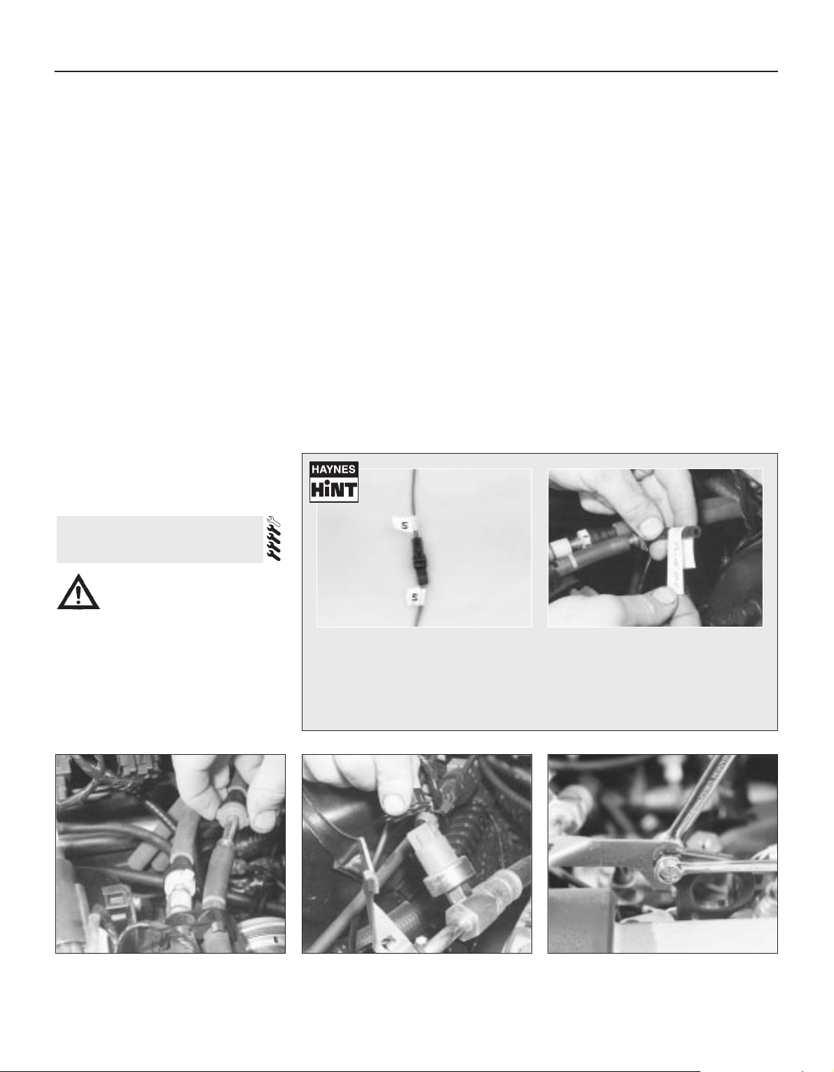
safely and with relative ease, and which may
have to be hired or borrowed, includes (in
addition to the engine hoist) a heavy-duty trolley
jack, a strong pair of axle stands, some wooden
blocks, and an engine dolly (a low, wheeled
platform capable of taking the weight of the
engine/transmission, so that it can be moved
easily when on the ground). A complete set of
spanners and sockets (as described in the front
of this manual) will obviously be needed,
together with plenty of rags and cleaning
solvent for mopping-up spilled oil, coolant and
fuel. If the hoist is to be hired, make sure that
you arrange for it in advance, and perform all of
the operations possible without it beforehand.
This will save you money and time.
Plan for the vehicle to be out of use for
quite a while. A machine shop will be required
to perform some of the work which the do-ityourselfer can’t accomplish without special
equipment. These establishments often have
a busy schedule, so it would be a good idea
to consult them before removing the engine,
to accurately estimate the amount of time
required to rebuild or repair components that
may need work.
Always be extremely careful when removing
and installing the engine/transmission.
Serious injury can result from careless
actions. By planning ahead and taking your
time, the job (although a major task) can be
accomplished successfully.
Warning: Petrol is extremely
flammable, so take extra
precautions when disconnecting
any part of the fuel system. Don’t
smoke, or allow naked flames or bare light
bulbs in or near the work area, and don’t
work in a garage where a natural gas
appliance (such as a clothes dryer or water
heater) is installed. If you spill petrol on
your skin, rinse it off immediately. Have a
fire extinguisher rated for petrol fires
handy, and know how to use it.
Note: Read through the entire Section, as well
as reading the advice in the preceding Section,
before beginning this procedure. The engine
and transmission are removed as a unit,
lowered to the ground and removed from
underneath, then separated outside the vehicle.
Removal
1 Park the vehicle on firm, level ground, apply
the handbrake firmly, and slacken the nuts
securing both front roadwheels.
2 Relieve the fuel system pressure (see
Chapter 4).
3 Disconnect the battery negative (earth) lead
- see Chapter 5, Section 1. For better access
the battery may be removed completely (see
Chapter 5).
4 Place protective covers on the wings and
engine compartment front crossmember, then
remove the bonnet (see Chapter 11).
5 Whenever you disconnect any vacuum
lines, coolant and emissions hoses, wiring
loom connectors, earth straps and fuel lines
as part of the following procedure, always
label them clearly, so that they can be
correctly reassembled.
6 Unplug the two electrical connectors,
disconnect the vacuum hose (where fitted)
and disconnect the crankcase breather hose
from the cylinder head cover, then remove the
complete air cleaner assembly, with the air
mass meter, the resonator and the plenum
chamber (see Chapter 4).
7 Equalise the pressure in the fuel tank by
removing the filler cap, then undo the fuel
feed and return lines connecting the engine to
the chassis (see Chapter 4). Plug or cap all
open fittings (see illustration).
8 Disconnect the accelerator cable from the
throttle linkage as described in Chapter 4 where fitted, also disconnect the cruise
control actuator cable (see Chapter 12).
Secure the cable(s) clear of the
engine/transmission.
9 Releasing its wire clip, unplug the power
steering pressure switch electrical connector,
then unbolt the power steering high-pressure
pipe and the earth lead from the cylinder head
rear support plate/engine lifting eye (see
illustrations).
10 Marking or labelling all components as
they are disconnected (see paragraph 5
above), disconnect the vacuum hoses as
follows:
4 Engine/transmission -
removal and refitting
2B•4 Engine removal and general engine overhaul procedures
4.7 Note colour-coding of unions when
disconnecting fuel feed and return lines
4.9A Unplug the power steering pressure
switch electrical connector . . .
4.9B . . . unbolt the power steering highpressure pipe . . .
Whenever any wiring is disconnected, . . . vacuum hoses and pipes should
mark or label it as shown, to ensure be similarly marked
correct reconnection . . .
Masking tape and/or a touch-up paint applicator work well for marking items. Take
instant photos, or sketch the locations of components and brackets.
Page 71
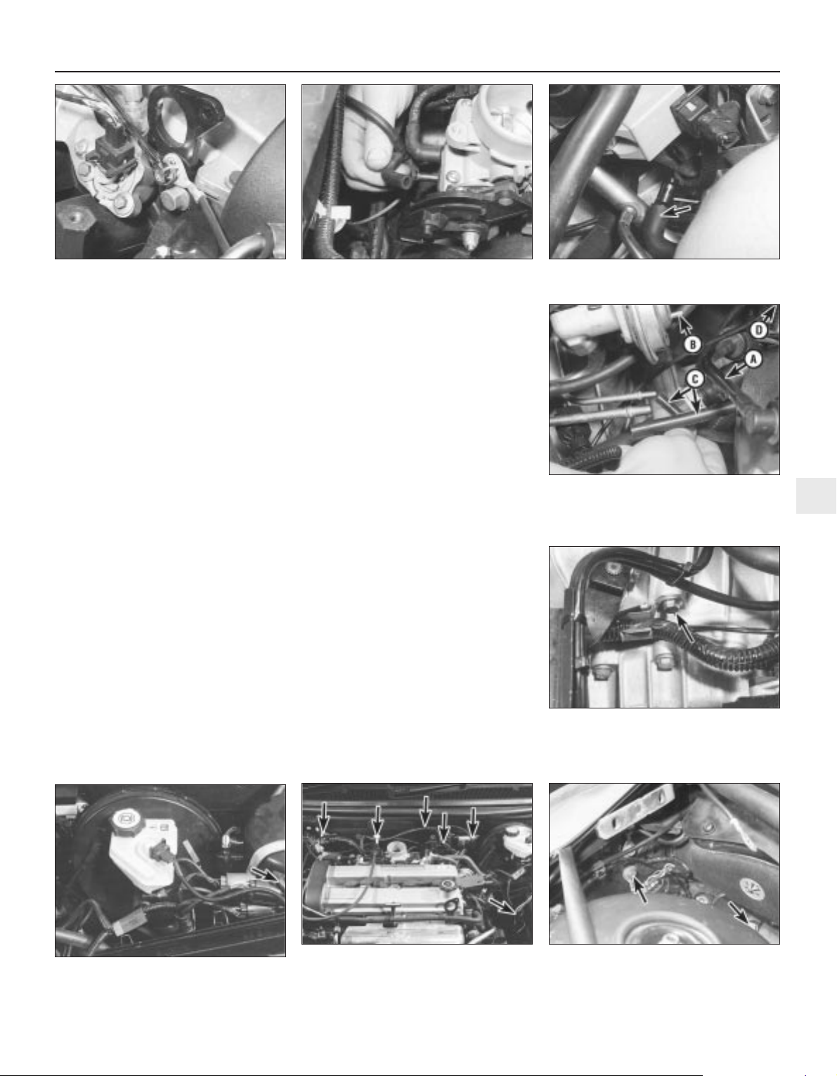
(a) One from the rear of the throttle housing
(only the one hose - there is no need to
disconnect the second hose running to
the fuel pressure regulator) (see
illustration).
(b) One from the union on the inlet manifold’s
left-hand end (see illustration).
(c) The braking system vacuum servo unit
hose - from the inlet manifold (see
Chapter 9 for details).
(d) Also disconnect the vacuum hoses from
the Exhaust Gas Recirculation system
components - one from the EGR valve,
two from the EGR pipe (note that these
last two are of different sizes, as are their
pipe stubs, so that they can only be
connected the correct way round).
(e) While you are there, trace the vacuum line
from the pulse-air filter housing over the
top of the transmission, and disconnect it
by pulling the plastic pipe out of the
rubber hose just beneath the bulkheadmounted pulse-air solenoid valve (see
illustration).
(f) Secure all these hoses so that they won’t
get damaged as the engine/transmission
is removed.
11 Unbolt the engine/transmission-to-body
earth lead from the transmission’s top surface
(see illustration). Disconnect the speedometer drive cable (see Chapter 12) and
secure it clear of the engine/transmission.
12 Where the vehicle is fitted with manual
transmission, disconnect the clutch cable (see
Chapter 8). Where automatic transmission is
fitted, disconnect the selector cable (see
Chapter 7, Part B). Secure the cable clear of
the engine/transmission.
13 Marking or labelling all components as
they are disconnected (see paragraph 5
above), disconnect the engine wiring loom
from the body as follows:
(a) Starting at the left-hand side of the engine
compartment, release and unplug the
three large electrical connectors clipped
to the suspension mounting - note the
wire clips fitted to some connectors (see
illustration).
(b) Disconnect and/or release the battery-to-
starter motor wiring, noting the single
connector which must be unplugged.
(c) Unplug the electrical connector(s) to
disconnect the vehicle speed sensor,
oxygen sensor and, where fitted, the oil
level sensor wiring - unclip the connectors
to release the wiring where necessary.
(d) Work along the loom to the bulkhead,
unclipping the loom and unplugging the
various bulkhead-mounted components
connected into it, until you reach the
right-hand side of the engine
compartment (see illustration).
(e) Carefully prise the power steering fluid
reservoir upwards out of its clip on the
suspension mounting, then unscrew the
ECU connector’s retaining bolt and
unplug the connector (see illustration).
(f) Unbolt the earth lead from the right-hand
Engine removal and general engine overhaul procedures 2B•5
2B
4.13A Unplug three large electrical
connectors (arrowed) . . .
4.13B . . . unplug engine wiring loom from
battery wiring and bulkhead components
(arrowed) . . .
4.13C . . . and disconnect ECU wiring and
earth lead (arrowed) to release engine
wiring loom from vehicle body
4.9C . . . and the earth lead from the
cylinder head rear support plate/engine
lifting eye
4.10A Disconnect vacuum hose shown
from rear of throttle housing . . .
4.10B . . . vacuum hose (arrowed) from
union on left-hand end on inlet manifold . . .
4.10C . . . also brake servo hose (A), EGR
valve hose (B), EGR pipe hoses (C) - noting
their different sizes - and pulse-air filter
vacuum line (D)
4.11 Unbolt the engine/transmission-tobody earth lead - hidden behind wiring
loom guide - from location (arrowed) on
the transmission’s top surface
Page 72
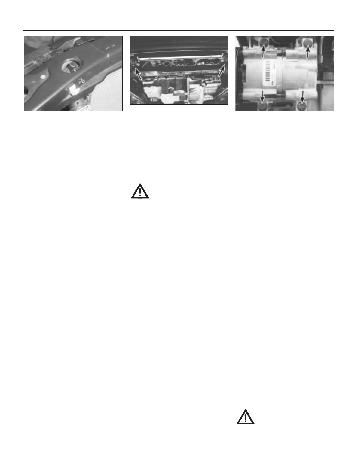
inner wing panel, release the engine
wiring loom and refit the power steering
fluid reservoir.
(g) Secure the engine wiring loom neatly to
the engine/transmission so that it cannot
be damaged as the unit is removed from
the vehicle.
14 Unbolt both parts of the exhaust manifold
heat shield; unclip the coolant hose to allow
the upper part to be withdrawn.
15 Remove the auxiliary drivebelt (see
Chapter 1).
16 Unbolt the power steering pump (see
Chapter 10); secure it as far as possible
(without disconnecting the system’s hoses)
clear of the engine/transmission.
17 Raise the vehicle and support it securely
on axle stands, then remove the front
roadwheels. Drain the cooling system and (if
the engine is to be dismantled) drain the
engine oil and remove the oil filter (see
Chapter 1). Also drain the transmission as
described in the relevant Part of Chapter 7.
18 Withdraw the lower part of the exhaust
manifold heat shield.
19 Unscrew the nuts to disconnect the
exhaust system front downpipe from the
manifold, then unhook all the system’s rubber
mountings and withdraw the complete
exhaust system from under the vehicle (see
Chapter 4 for details).
20 Where the vehicle is fitted with manual
transmission, mark their positions, then
disconnect the gearchange linkage and
transmission support rods from the rear of the
transmission. Unscrew the retaining nuts, and
withdraw the gear linkage heat shield from the
underbody. Unbolt the rear end of the linkage
from the underbody, swivel the linkage around
to the rear, and tie it to the underbody (see
Chapter 7, Part A, for details).
21 Disconnect both anti-roll bar links from
their respective suspension strut - note the
flexible brake hose bracket attached to each
link stud - and both track rod ends from their
steering knuckles. Unfasten the clamp bolt
securing each front suspension lower arm
balljoint to its steering knuckle (see Chapter 10 for details). Check that both balljoints
can be released from the knuckle assemblies
when required, but leave them in place for the
time being, secured by the clamp bolts if
necessary.
22 Where the vehicle is fitted with air
conditioning, unbolt the accumulator/
dehydrator from the subframe; secure it as far
as possible (without disconnecting the
system’s hoses) clear of the engine/
transmission.
Warning: Do not disconnect the
refrigerant hoses.
23 Unbolt the steering gear from the
subframe; if the bolts are not accessible from
above, a Ford service tool will be required to
reach them from underneath the vehicle (see
Chapter 10 for details).
24 Unscrew the two bolts securing the power
steering system pipes to the right-hand side
of the subframe.
25 Hold the radiator in its raised position, by
inserting split pins through the holes in the
rear of the engine compartment front
crossmember and into the radiator’s upper
mounting extensions. Unbolt the radiator
mounting brackets from the subframe; note
that they are handed, and are marked to
ensure correct refitting (see illustrations).
Collect and store the bottom mounting
rubbers for safekeeping, noting which way up
they are fitted.
26 Unbolt the engine/transmission rear
mounting from the subframe - where the
vehicle is fitted with automatic transmission, a
separate damper may be fitted beneath the
subframe, which must be unbolted to reach
the mounting’s fasteners. Where the vehicle is
fitted with manual transmission, also unscrew
the mounting centre bolt, and unbolt the
mounting bracket from the transmission.
27 Unscrew the engine/transmission front
mounting centre bolt, and unbolt the
mounting from the subframe, noting the
location of the wiring connector bracket.
28 Use white paint or similar (do not use a
sharp-pointed scriber, which might break the
underbody protective coating and cause
rusting) to mark the exact relationship of the
subframe to the underbody. Unscrew the four
mounting bolts from the subframe (note their
different-sized washers - see also illus-
tration 4.47A) and allow the subframe to hang
down on the suspension lower arm balljoints.
Disconnect the balljoints one at a time from
the steering knuckle assemblies (see Chapter 10) and lower the subframe to the ground;
withdraw the subframe from under the
vehicle.
29 Marking or labelling all components as
they are disconnected (see paragraph 5
above) and catching as much as possible of
the escaping coolant in the drain tray,
disconnect the cooling system hoses and
pipes as follows - refer to Chapter 3 for further
details, if required:
(a) Remove the radiator top hose.
(b) Remove the (heater) hose running from
the thermostat to the engine
compartment bulkhead union.
(c) Disconnect from the thermostat the hose
running to the expansion tank - secure the
hose clear of the working area.
(d) Disconnect from the thermostat the
coolant hose/pipe which runs to the
radiator bottom hose.
(e) Disconnect the radiator bottom hose from
the radiator union, from the (sump) heater
coolant pipe and from the water pump
union - secure the hose clear of the
working area.
(f) Unbolt the (heater) coolant pipe from the
sump, trace the pipe/hose round to the
engine compartment bulkhead union,
disconnecting (where fitted) the oil cooler
hoses from the cooler unions, then
remove it.
(g) Unless the vehicle has air conditioning
fitted, secure the radiator as far forwards
as possible while it is in its raised position;
if air conditioning is fitted, remove the
radiator completely (see Chapter 3).
30 Where the vehicle is fitted with air
conditioning, unplug the compressor’s
electrical connector, and unbolt the
compressor from the engine (see
illustration). Secure it as far as possible
(without disconnecting the system’s hoses)
clear of the engine/transmission.
Warning: Do not disconnect the
refrigerant hoses.
2B•6 Engine removal and general engine overhaul procedures
4.25A Use split pins as shown to secure
radiator in its raised position . . .
4.25B . . . while you unbolt the bottom
mountings (arrowed) - note that the
mountings are handed, and do not lose the
mounting rubbers
4.30 Unscrew bolts (arrowed) to release
air conditioning compressor from engine
Page 73
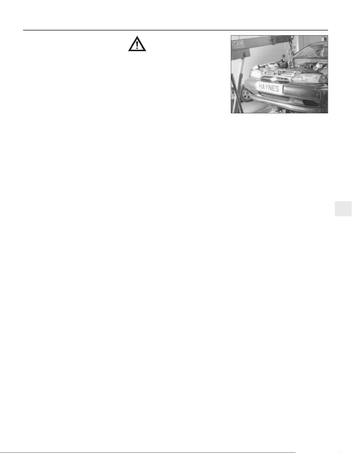
31 Where the vehicle is fitted with manual
transmission, disconnect the driveshafts from
the transmission as follows, referring to
Chapter 8 for further details when required:
(a) Unscrew the nuts securing the right-hand
driveshaft support bearing, and withdraw
the heat shield.
(b) Pull the right-hand driveshaft out of the
transmission; be prepared to catch any
spilt oil.
(c) Secure the driveshaft clear of the
engine/transmission - remember that the
unit is to be lowered out of the vehicle and ensure that the inner joint is not
turned through more than 18°.
(d) Prise the left-hand driveshaft out of the
transmission - again, be prepared for oil
spillage. Secure the driveshaft clear of the
engine/transmission, and ensure that its
inner joint is not turned through more than
18°.
32 Where the vehicle is fitted with automatic
transmission, proceed as follows, referring to
Chapter 7, Part B and to Chapter 8 for further
details when required:
(a) Unscrew its centre bolt, then unbolt the
engine/transmission rear mounting
bracket from the transmission.
(b) Disconnect the fluid cooler pipe from the
rear of the transmission, and secure it
clear of the unit.
(c) Prise the left-hand driveshaft out of the
transmission; be prepared to catch any
spilt oil.
(d) Secure the driveshaft clear of the
engine/transmission - remember that the
unit is to be lowered out of the vehicle and ensure that the inner joint is not
turned through more than 18°.
(e) Unscrew the nuts securing the right-hand
driveshaft support bearing, and withdraw
the heat shield.
(f) Pull the right-hand driveshaft out of the
transmission - again, be prepared for oil
spillage. Secure the driveshaft clear of the
engine/transmission, and ensure that its
inner joint is not turned through more than
18°.
(g) Disconnect the fluid cooler pipe from the
front of the transmission, and secure it
clear of the unit.
33 The engine/transmission unit should now
be hanging on the right- and left-hand
mountings only, with all components which
connect it to the rest of the vehicle
disconnected or removed and secured well
clear of the unit. Make a final check that this is
the case, then ensure that the body is
securely supported, high enough to permit the
withdrawal of the engine/transmission unit
from underneath; allow for the height of the
engine dolly, if used.
34 Take the weight of the engine/
transmission unit, using the lifting eyes
provided on the cylinder head. Unscrew the
six nuts securing the right-hand mounting
bracket, then the three nuts securing the lefthand bracket.
Warning: Do not put any part of
your body under the vehicle, or
under the engine/transmission
unit, when they are supported only by a
hoist or other lifting equipment.
35 Lower the engine/transmission to the
ground, and withdraw it from under the
vehicle (see illustration).
36 Referring to the relevant part of Chapter 7,
separate the transmission from the engine.
37 While the engine/transmission is removed,
check the mountings; renew them if they are
worn or damaged. Similarly, check the
condition of all coolant and vacuum hoses
and pipes (see Chapter 1); components that
are normally hidden can now be checked
properly, and should be renewed if there is
any doubt at all about their condition. Where
the vehicle is fitted with manual transmission,
take the opportunity to overhaul the clutch
components (see Chapter 8). It is regarded by
many as good working practice to renew the
clutch assembly as a matter of course,
whenever major engine overhaul work is
carried out. Check also the condition of all
components (such as the transmission oil
seals) disturbed on removal, and renew any
that are damaged or worn.
Refitting
38 Refitting is the reverse of the removal
procedure, noting the following points.
Tighten all fasteners to the torque wrench
settings given; where settings are not quoted
in the Specifications Sections of the two Parts
of this Chapter, refer to the Specifications
Section of the relevant Chapter of this manual.
39 In addition to the points noted in
paragraph 37 above, always renew any
circlips and self-locking nuts disturbed on
removal.
40 Where wiring, etc, was secured by cable
ties which had to be cut on removal, ensure
that it is secured with new ties on refitting.
41 With all overhaul operations completed,
refit the transmission to the engine as
described in Chapter 7.
42 Manoeuvre the engine/transmission unit
under the vehicle, attach the hoist, and lift the
unit into position until the right- and left-hand
mountings can be reassembled; tighten the
(new) nuts only lightly at this stage. Do not yet
release the hoist; the weight of the
engine/transmission unit must not be taken by
the mountings until all are correctly aligned.
43 Using new circlips, and ensuring that the
inner joints are not twisted through too great
an angle (see Chapter 8), refit the driveshafts.
Where the vehicle is fitted with manual
transmission, the procedure is the reverse of
that outlined in paragraph 31 above. Where
the vehicle is fitted with automatic
transmission, proceed as follows, referring to
Chapter 7, Part B and to Chapter 8 for further
details when required:
(a) Refit the left-hand driveshaft.
(b) Using the clips provided to ensure that
they are correctly routed, and tightening
the couplings to the specified torque
wrench setting where possible, reconnect
the fluid cooler pipes, first to the rear,
then to the front, of the transmission.
(c) Refit the right-hand driveshaft to the
transmission, refit the heat shield, and
tighten the support bearing nuts to the
specified torque wrench setting.
(d) Refit the engine/transmission rear
mounting bracket to the transmission,
tightening the bolts to the torque wrench
setting specified, then refit the mounting,
tightening the centre bolt only lightly at
this stage.
44 Where the vehicle is fitted with air
conditioning, do not forget to refit the
compressor; tighten the bolts to the specified
torque wrench setting, and plug in its
electrical connector.
45 Using the marks and notes made on
removal, refit the cooling system hoses.
Where they are left disconnected or unclipped
for the time being, do not forget to secure
them at the appropriate moment during the
reassembly procedure. Refit the radiator (if
removed), using split pins to secure it in the
raised position.
46 Offer up the subframe one side at a time,
and hold it by securing the suspension lower
arm balljoints to the steering knuckle
assemblies. Refit the subframe bolts, ensuring
that the washers are refitted correctly, and
tightening the bolts only lightly at this stage.
47 The subframe must now be aligned on the
underbody. Ford specify the use of service
tool 15-097, which is a pair of tapered guides,
with attachments to hold them in the
subframe as it is refitted. However, since the
working diameter of these tools is 20.4 mm,
and since the corresponding aligning holes in
the subframe and underbody are respectively
21 mm and 22 mm in diameter, there is a
significant in-built tolerance possible in the
subframe’s alignment, even if the correct tools
are used. If these tools are not available, you
can align the subframe by eye, centring the
subframe aligning holes on those of the
underbody, and using the marks made on
removal for assistance. Alternatively, you can
align the subframe using a tapered drift (such
as a clutch-aligning tool), or even a deep
Engine removal and general engine overhaul procedures 2B•7
2B
4.35 Lowering the engine/transmission
unit out of the vehicle
Page 74
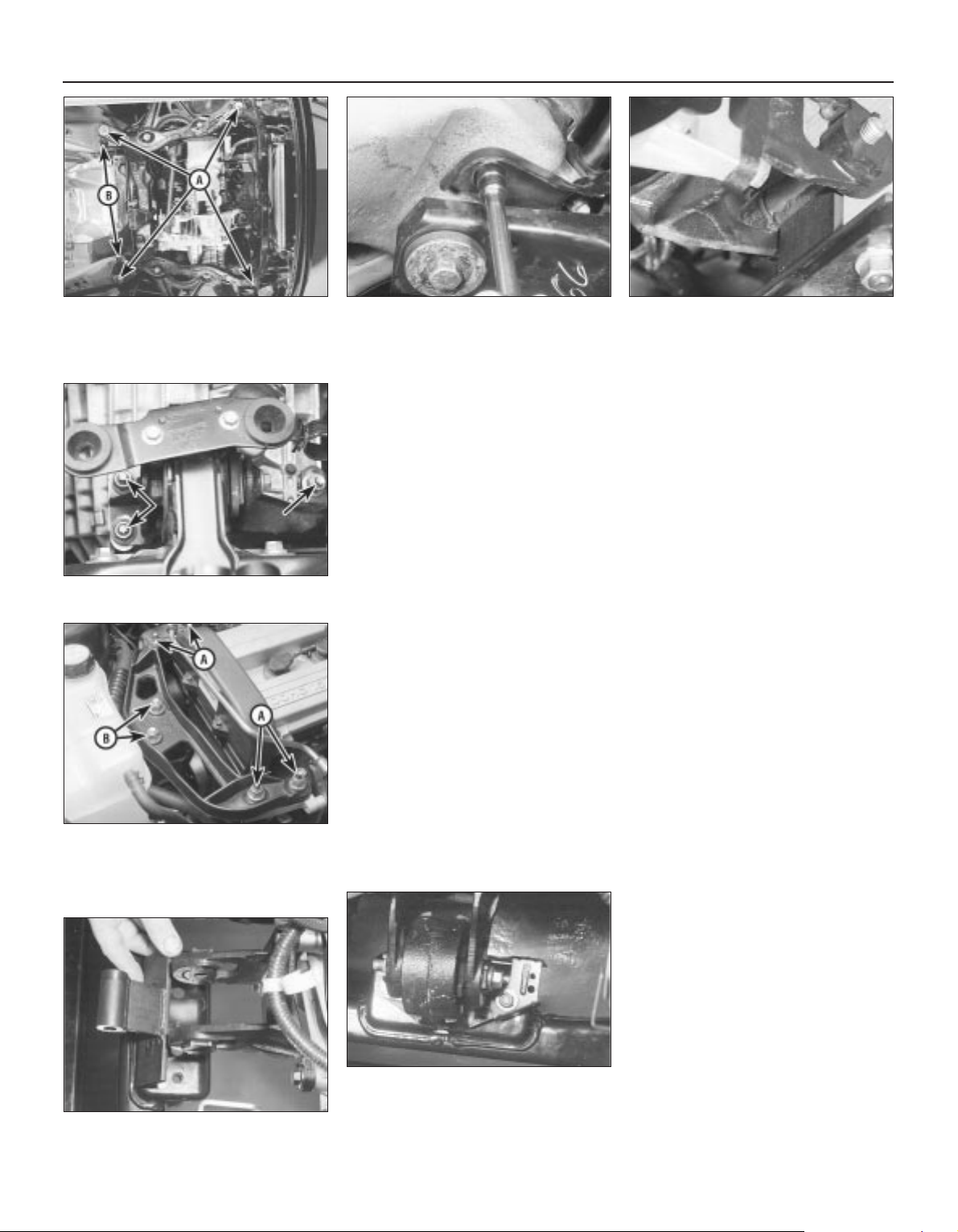
socket spanner of suitable size (see
illustrations).
48 Once the subframe is aligned as precisely
as possible, tighten its bolts to the specified
torque wrench setting without disturbing its
position. Recheck the alignment once all the
bolts are securely tightened.
49 With the subframe aligned and securely
fastened, the engine/transmission unit must
now be positioned precisely, before the
mountings can be reassembled. Ford specify
the use of service tool 21-172; this is a fixture
bolted to the subframe in place of the
engine/transmission front mounting, so that
when the mounting’s centre bolt is refitted, it
is held 60 mm above the subframe’s top
surface, and offset 20 mm to the rear of the
mounting’s subframe bolt holes (centres). DIY
mechanics are advised to obtain the Ford
tool; the only alternative is to have a copy
fabricated (see illustration).
50 Fasten the tool to the subframe in place of
the engine/transmission front mounting, and
lightly tighten the mounting’s centre bolt. Refit
the engine/transmission mountings in the
following sequence:
(a) Tighten the left-hand mounting’s nuts to
the specified torque wrench setting - do
not allow the mounting to twist as it is
tightened (see illustration).
(b) Tighten the right-hand mounting’s four
bracket-to-engine nuts to the specified
torque wrench setting.
(c) Slowly release the hoist so that the weight
of the engine/transmission unit is taken by
the mountings.
(d) Tighten the right-hand mounting’s two
bracket-to-mounting nuts to the specified
torque wrench setting - do not allow the
mounting to twist as it is tightened (see
illustration).
(e) Reassemble the engine/transmission rear
mounting, tightening the fasteners to the
specified torque wrench settings; tighten
the centre bolt last.
(f) Refit the steering gear to the subframe; if
the Ford service tool is used to tighten the
bolts from underneath the vehicle (see
Chapter 10 for details), note that a torque
wrench which can tighten in an anticlockwise direction will be required.
(g) Unbolt the special tool from the front
mounting, refit the mounting - do not
forget the wiring connector bracket - and
tighten first the mounting’s bolts/nuts,
then its centre bolt, to their respective
specified torque wrench settings (see
illustrations).
51 Refit the bottom mounting rubbers to the
radiator - ensure that both are the correct way
up - then refit the radiator mounting brackets
to the subframe, ensuring that each is
returned to its correct (marked) location, and
tightening the bolts to the torque wrench
setting specified. Remove the split pins, and
secure the coolant hose connections (where
necessary).
52 Refit the air conditioning accumulator/
dehydrator (where appropriate) to the
subframe.
53 Tighten the two bolts securing the power
steering system pipes to the right-hand side
of the subframe.
54 Fasten each front suspension lower arm
balljoint and track rod end to their respective
steering knuckles, and both anti-roll bar links
to their respective suspension strut. Note the
flexible brake hose bracket attached to each
link stud (see Chapter 10 for details).
55 Where the vehicle is fitted with manual
transmission, swivel the linkage around to the
front, tighten its rear fasteners, then refit the
2B•8 Engine removal and general engine overhaul procedures
4.47A Tighten subframe mounting
bolts (A) while ensuring that alignment
remains correct - Ford service tools (B)
shown in use here . . .
4.47B . . . but alternative methods using
ordinary hand tools can achieve
acceptable alignment, with care
4.49 Special tool required to hold
engine/transmission unit precisely, so that
mountings can be tightened into correct
position
4.50B Tighten the right-hand mounting’s
four bracket-to-engine nuts (A), release
the hoist, then tighten the two bracket-to-
mounting nuts (B). Do not allow mounting
to twist
4.50A Do not allow the left-hand mounting
to twist as its nuts (arrowed) are tightened
4.50C Unbolt special tool . . .
4.50D . . . then refit front mounting - do
not forget wiring connector bracket -
tighten the mounting’s nuts first, then its
centre bolt
Page 75
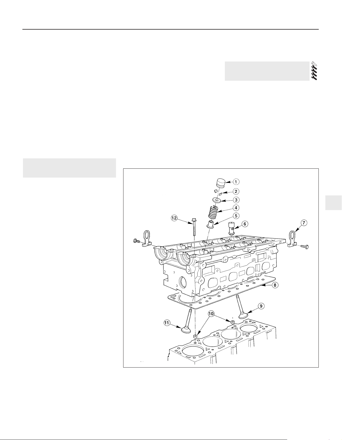
gear linkage heat shield. Reconnect the
gearchange linkage and transmission support
rods to the transmission, adjusting the linkage
using the marks made on removal (see
Chapter 7, Part A, for details).
56 Re-install the remaining components and
fasteners in the reverse order of removal.
57 Add coolant, engine oil and transmission
fluids as needed (see Chapter 1).
58 Run the engine, and check for proper
operation and the absence of leaks. Shut off
the engine, and recheck the fluid levels.
59 Remember that, since the front suspension
subframe and steering gear have been
disturbed, the wheel alignment and steering
angles must be checked fully and carefully as
soon as possible, with any necessary
adjustments being made. This operation is best
carried out by an experienced mechanic, using
proper checking equipment; the vehicle should
therefore be taken to a Ford dealer or similarlyqualified person for attention.
1 It is much easier to dismantle and work on
the engine if it is mounted on a portable engine
stand. These stands can often be hired from a
tool hire shop. Before the engine is mounted
on a stand, the flywheel/driveplate should be
removed (Part A of this Chapter, Section 21)
so that the stand bolts can be tightened into
the end of the cylinder block/crankcase.
2 If a stand is not available, it is possible to
dismantle the engine with it mounted on
blocks, on a sturdy workbench or on the floor.
Be extra-careful not to tip or drop the engine
when working without a stand.
3 If you are going to obtain a reconditioned
engine, all external components must be
removed first, to be transferred to the
replacement engine (just as they will if you are
doing a complete engine overhaul yourself).
Note: When removing the external
components from the engine, pay close
attention to details that may be helpful or
important during refitting. Note the fitted
position of gaskets, seals, spacers, pins,
washers, bolts and other small items. These
external components include the following:
(a) Alternator and brackets (Chapter 5).
(b) HT leads and spark plugs (Chapter 1).
(c) Thermostat and housing (Chapter 3).
(d) Dipstick tube.
(e) Fuel injection system components
(Chapter 4).
(f) All electrical switches and sensors - refer
to the appropriate Chapter.
(g) Inlet and exhaust manifolds (Part A of this
Chapter).
(h) Oil filter (Chapter 1).
(i) Engine/transmission mounting brackets
(Part A of this Chapter, Section 22).
(j) Flywheel/driveplate (Part A of this
Chapter, Section 21).
4 If you are obtaining a “short” engine (which
consists of the engine cylinder
block/crankcase, crankshaft, pistons and
connecting rods all assembled), then the
cylinder head, sump, oil pump, and timing belt
will have to be removed also.
5 If you are planning a complete overhaul, the
engine can be dismantled and the internal
components removed in the following order.
(a) Inlet and exhaust manifolds (Part A of this
Chapter).
(b) Timing belt, toothed pulleys and
tensioner, and timing belt inner cover
(Part A of this Chapter).
(c) Cylinder head (Part A of this Chapter,
Section 14).
(d) Flywheel/driveplate (Part A of this
Chapter, Section 21).
(e) Sump (Part A of this Chapter, Section 15).
(f) Oil pump (Part A of this Chapter, Sec-
tion 16).
(g) Piston/connecting rod assemblies
(Section 9).
(h) Crankshaft (Section 10).
6 Before beginning the dismantling and
overhaul procedures, make sure that you have
all of the correct tools necessary. Refer to the
introductory pages at the beginning of this
manual for further information.
Note: New and reconditioned cylinder heads
are available from the manufacturers, and
from engine overhaul specialists. Due to the
fact that some specialist tools are required for
the dismantling and inspection procedures,
and new components may not be readily
available (refer to Section 1 of this Part), it may
be more practical and economical for the
home mechanic to purchase a reconditioned
head, rather than to dismantle, inspect and
recondition the original head.
1 Remove the camshafts and hydraulic
tappets (Part A of this Chapter, Section 13),
being careful to store the hydraulic tappets as
described (see illustration).
6 Cylinder head - dismantling
5 Engine overhaul -
dismantling sequence
Engine removal and general engine overhaul procedures 2B•9
2B
6.1 Cylinder head components
1 Hydraulic tappet
2 Valve collets
3 Valve spring upper seat
4 Valve spring
5 Valve spring lower
seat/stem oil seal
6 Oil-retaining valve
7 Engine lifting eye
8 Cylinder head gasket
9 Inlet valve
10 Locating dowels
11 Exhaust valve
12 Cylinder head bolt
Page 76
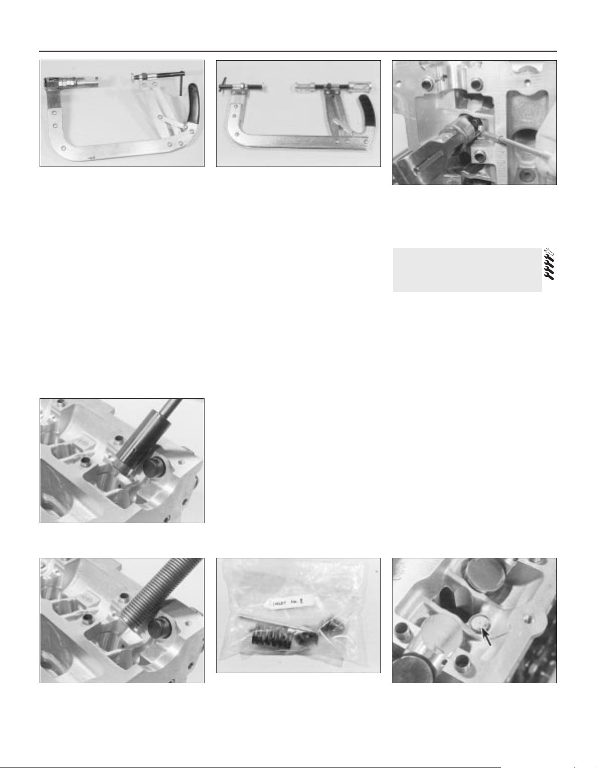
2 Remove the cylinder head (Part A of this
Chapter, Section 14).
3 Using a valve spring compressor, compress
each valve spring in turn until the split collets
can be removed. A special valve spring
compressor will be required, to reach into the
deep wells in the cylinder head without risk of
damaging the hydraulic tappet bores; such
compressors are now widely available from
most good motor accessory shops. Release
the compressor, and lift off the spring upper
seat and spring (see illustrations).
4 If, when the valve spring compressor is
screwed down, the spring upper seat refuses
to free and expose the split collets, gently tap
the top of the tool, directly over the upper
seat, with a light hammer. This will free the
seat.
5 Withdraw the valve through the combustion
chamber. If it binds in the guide (won’t pull
through), push it back in, and de-burr the area
around the collet groove with a fine file or
whetstone; take care not to mark the
hydraulic tappet bores.
6 Ford recommend the use of their service
tool 21-160 to extract the valve spring lower
seat/stem oil seals; while this is almost
indispensable if the seals are to be removed
without risk of (extremely expensive) damage
to the cylinder head, we found that a
serviceable substitute can be made from a
strong spring of suitable size. Screw on the
tool or spring so that it bites into the seal, then
draw the seal off the valve guide (see
illustrations).
7 It is essential that the valves are kept
together with their collets, spring seats and
springs, and in their correct sequence (unless
they are so badly worn that they are to be
renewed). If they are going to be kept and
used again, place them in a labelled polythene
bag or similar small container (see
illustration). Note that No 1 valve is nearest to
the timing belt end of the engine.
8 If the oil-retaining valve is to be removed (to
flush out the cylinder head oil galleries
thoroughly), seek the advice of a Ford dealer
as to how it can be extracted; it may be that
the only course of action involves destroying
the valve as follows. Screw a self-tapping
screw into its ventilation hole, and use the
screw to provide purchase with which the
valve can be drawn out; a new valve must be
purchased and pressed into place on
reassembly (see illustration).
Note: Always check first what replacement
parts are available before planning any
overhaul operation; refer to Section 1 of this
Part. A Ford dealer, or a good engine
reconditioning specialist/automotive parts
supplier, may be able to suggest alternatives
which will enable you to overcome the lack of
replacement parts.
1 Thorough cleaning of the cylinder head and
valve components, followed by a detailed
inspection, will enable you to decide how
much valve service work must be carried out
during the engine overhaul. Note: If the
engine has been severely overheated, it is best
to assume that the cylinder head is warped,
and to check carefully for signs of this.
Cleaning
2 Scrape away all traces of old gasket
material and sealing compound from the
cylinder head (see Part A of this Chapter,
Section 14 for details).
3 Scrape away the carbon from the
combustion chambers and ports, then wash
the cylinder head thoroughly with paraffin or a
suitable solvent.
7 Cylinder head and valve
components -
cleaning and inspection
2B•10 Engine removal and general engine overhaul procedures
6.3A Standard valve spring compressor
modified as shown . . .
6.3B . . . or purpose-built special version,
is required to compress valve springs
without damaging cylinder head . . .
6.3C . . . so that both valve split collets
can be removed from the valve’s stem -
small magnetic pick-up tool prevents loss
of small metal components on removal
and refitting
6.6B . . . can be replaced by home-made
tool if suitable spring can be found
6.6A Ford service tool in use to remove
valve spring lower seat/stem oil seals . . .
6.7 Use clearly-marked containers to
identify components and to keep matched
assemblies together
6.8 Cylinder head oil-retaining valve
(arrowed)
Page 77
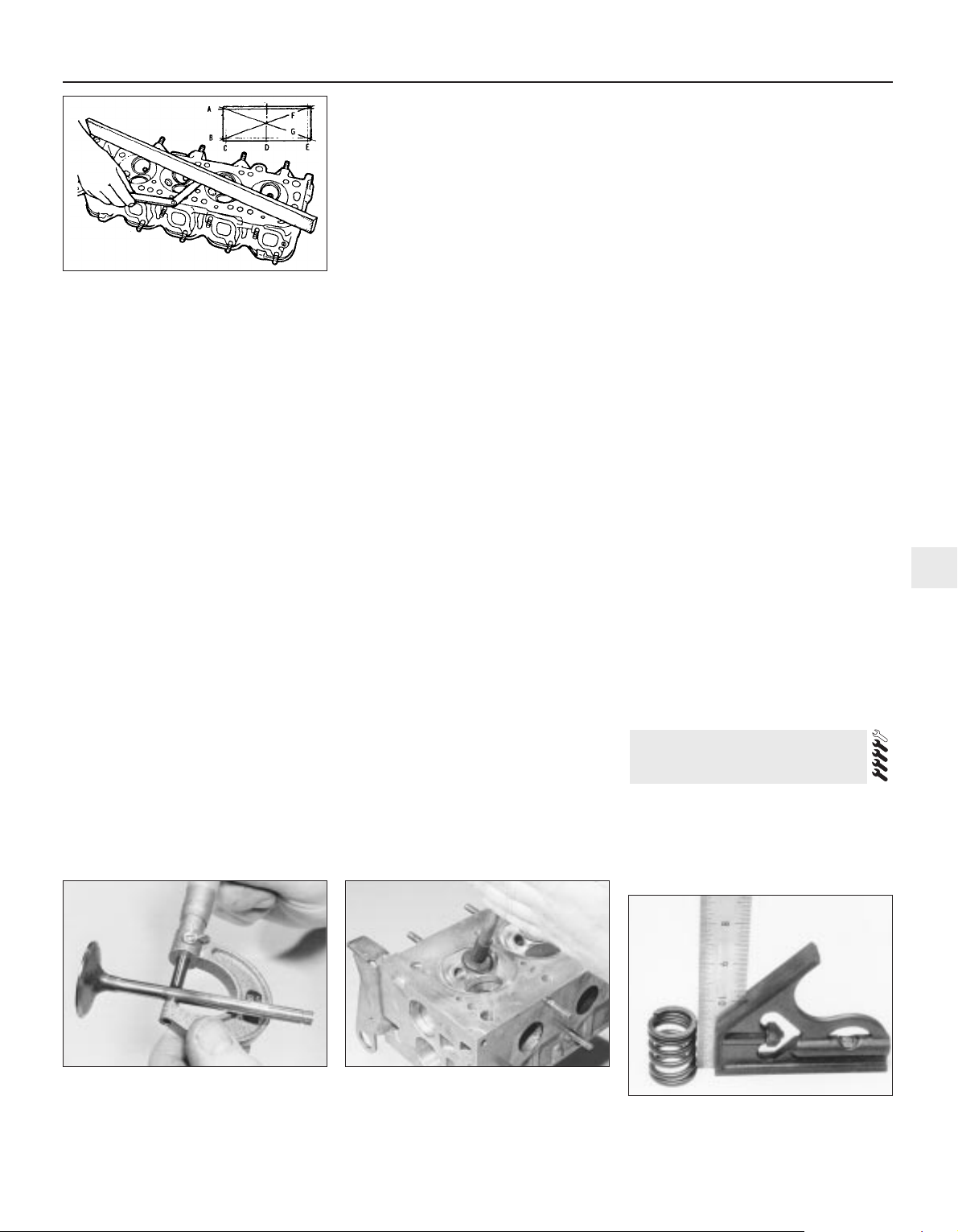
4 Scrape off any heavy carbon deposits that
may have formed on the valves, then use a
power-operated wire brush to remove
deposits from the valve heads and stems.
Inspection
Note: Be sure to perform all the following
inspection procedures before concluding that
the services of a machine shop or engine
overhaul specialist are required. Make a list of
all items that require attention.
Cylinder head
5 Inspect the head very carefully for cracks,
evidence of coolant leakage, and other
damage. If cracks are found, a new cylinder
head should be obtained.
6 Use a straight edge and feeler blade to
check that the cylinder head gasket surface is
not distorted (see illustration). If it is, it may
be possible to re-surface it.
7 Examine the valve seats in each of the
combustion chambers. If they are severely
pitted, cracked or burned, then they will need
to be renewed or re-cut by an engine overhaul
specialist. If they are only slightly pitted, this
can be removed by grinding-in the valve
heads and seats with fine valve-grinding
compound, as described below.
8 If the valve guides are worn, indicated by a
side-to-side motion of the valve, new guides
must be fitted. Measure the diameter of the
existing valve stems (see below) and the bore
of the guides, then calculate the clearance,
and compare the result with the specified
value; if the clearance is excessive, renew the
valves or guides as necessary.
9 The renewal of valve guides is best carried
out by an engine overhaul specialist.
10 If the valve seats are to be re-cut, this
must be done only after the guides have been
renewed.
Valves
11 Examine the head of each valve for
pitting, burning, cracks and general wear, and
check the valve stem for scoring and wear
ridges. Rotate the valve, and check for any
obvious indication that it is bent. Look for pits
and excessive wear on the tip of each valve
stem. Renew any valve that shows any such
signs of wear or damage.
12 If the valve appears satisfactory at this
stage, measure the valve stem diameter at
several points, using a micrometer (see
illustration). Any significant difference in the
readings obtained indicates wear of the valve
stem. Should any of these conditions be
apparent, the valve(s) must be renewed.
13 If the valves are in satisfactory condition,
they should be ground (lapped) into their
respective seats, to ensure a smooth gastight seal. If the seat is only lightly pitted, or if
it has been re-cut, fine grinding compound
only should be used to produce the required
finish. Coarse valve-grinding compound
should not be used unless a seat is badly
burned or deeply pitted; if this is the case, the
cylinder head and valves should be inspected
by an expert, to decide whether seat recutting, or even the renewal of the valve or
seat insert, is required.
14 Valve grinding is carried out as follows.
Place the cylinder head upside-down on a
bench, with a block of wood at each end to
give clearance for the valve stems.
15 Smear a trace of (the appropriate grade
of) valve-grinding compound on the seat face,
and press a suction grinding tool onto the
valve head. With a semi-rotary action, grind
the valve head to its seat, lifting the valve
occasionally to redistribute the grinding
compound (see illustration). A light spring
placed under the valve head will greatly ease
this operation.
16 If coarse grinding compound is being
used, work only until a dull, matt even surface
is produced on both the valve seat and the
valve, then wipe off the used compound, and
repeat the process with fine compound. When
a smooth unbroken ring of light grey matt
finish is produced on both the valve and seat,
the grinding operation is complete. Do not
grind in the valves any further than absolutely
necessary, or the seat will be prematurely
sunk into the cylinder head.
17 When all the valves have been ground-in,
carefully wash off all traces of grinding
compound, using paraffin or a suitable
solvent, before reassembly of the cylinder
head.
Valve components
18 Examine the valve springs for signs of
damage and discolouration, and also measure
their free length by comparing each of the
existing springs with a new component.
19 Stand each spring on a flat surface, and
check it for squareness (see illustration). If
any of the springs are damaged, distorted, or
have lost their tension, obtain a complete set
of new springs.
20 Check the spring upper seats and collets
for obvious wear and cracks. Any
questionable parts should be renewed, as
extensive damage will occur if they fail during
engine operation. Any damaged or
excessively-worn parts must be renewed; the
valve spring lower seat/stem oil seals must be
renewed as a matter of course whenever they
are disturbed.
21 Check the hydraulic tappets as described
in Part A of this Chapter, Section 13.
1 Regardless of whether or not the head was
sent away for repair work of any sort, make
sure that it is clean before beginning
reassembly. Be sure to remove any metal
particles and abrasive grit that may still be
present from operations such as valve
8 Cylinder head - reassembly
Engine removal and general engine overhaul procedures 2B•11
2B
7.12 Measuring the diameter of a valve
stem - if any significant difference is found
in the readings obtained, excessive valve
stem wear is indicated
7.15 Grinding-in a valve seat - do not grind
in the valves any more than absolutely
necessary, or their seats will be
prematurely sunk into the cylinder head
7.19 Check each valve spring for
squareness
7.6 Check the cylinder head gasket
surfaces for warpage, in the planes
indicated (A to G). Try to slip a feeler
gauge under the precision straight edge
(see the Specifications for the maximum
distortion allowed, and use a feeler blade
of that thickness)
Page 78
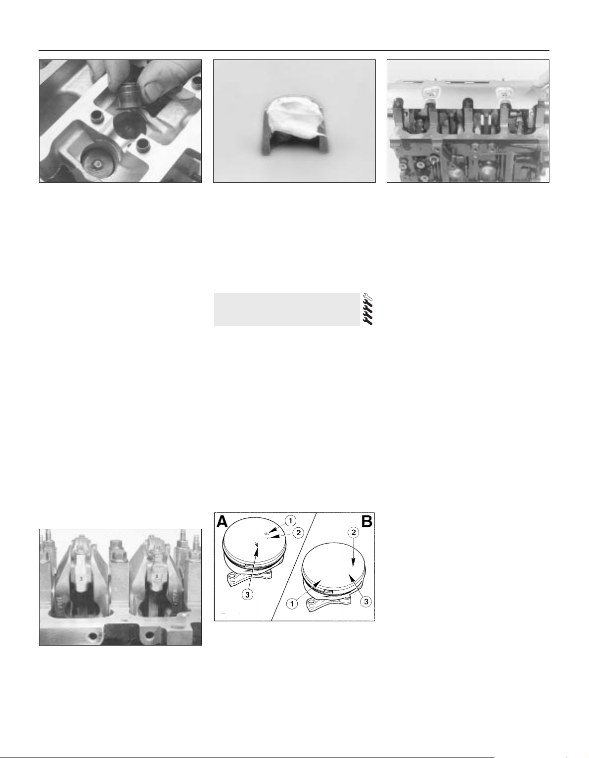
grinding or head resurfacing. Use
compressed air, if available, to blow out all the
oil holes and passages.
2 Beginning at one end of the head, lubricate
and install the first valve. Apply molybdenum
disulphide-based grease or clean engine oil to
the valve stem, and refit the valve. Where the
original valves are being re-used, ensure that
each is refitted in its original guide. If new
valves are being fitted, insert them into the
locations to which they have been ground.
3 Fit the plastic protector supplied with new
valve spring lower seat/stem oil seals to the
end of the valve stem, then put the new seal
squarely on top of the guide, and leave it
there; the action of refitting the valve spring
presses the lower seat/stem oil seal into place
(see illustration).
4 Refit the valve spring and upper seat.
5 Compress the spring with a valve spring
compressor, and carefully install the collets in
the stem groove. Apply a small dab of grease
to each collet to hold it in place if necessary
(see illustration). Slowly release the
compressor, and make sure the collets seat
properly.
6 When the valve is installed, place the
cylinder head flat on the bench and, using a
hammer and interposed block of wood, tap
the end of the valve stem gently, to settle the
components.
7 Repeat the procedure for the remaining
valves. Be sure to return the components to
their original locations - don’t mix them up!
8 Refit the hydraulic tappets (Part A of this
Chapter, Section 13).
Note: Always check first what replacement
parts are available before planning any
overhaul operation; refer to Section 1 of this
Part. A Ford dealer, or a good engine
reconditioning specialist/automotive parts
supplier, may be able to suggest alternatives
which will enable you to overcome the lack of
replacement parts.
Note: While this task is theoretically possible
when the engine is in place in the vehicle, in
practice, it requires so much preliminary
dismantling, and is so difficult to carry out due
to the restricted access, that owners are
advised to remove the engine from the vehicle
first. In addition to the new gaskets and other
replacement parts required, a hoist will be
needed. Alternatively, an adjustable engine
support bar, fitting into the water drain
channels on each side of the bonnet aperture,
and having a hook which will engage the
engine lifting eyes and allow the height of the
engine to be adjusted, could be used. Lifting
equipment such as this can be hired from
most tool hire shops - be sure that any such
equipment is rated well in excess of the
combined weight of the engine/transmission
unit.
1 Remove the cylinder head (Part A of this
Chapter, Section 14).
2 Bolt lifting eyes to suitable points on the
engine and transmission, then attach the
lifting equipment so that the engine/
transmission unit is supported securely.
3 Remove the sump (Part A of this Chapter,
Section 15).
4 Undo the screws securing the oil pump
pick-up/strainer pipe to the pump, then
unscrew the four nuts, and withdraw the oil
pump pick-up/strainer pipe and oil baffle (see
illustration).
5 Temporarily refit the crankshaft pulley, so
that the crankshaft can be rotated. Note that
each piston/connecting rod assembly can be
identified by its cylinder number (counting
from the timing belt end of the engine) etched
into the flat-machined surface of both the
connecting rod and its cap. The numbers are
visible from the front (exhaust side) of the
engine. Furthermore, each piston has an
arrow stamped into its crown, pointing
towards the timing belt end of the engine. If
no marks can be seen, make your own before
disturbing any of the components, so that you
can be certain of refitting each
piston/connecting rod assembly the right way
round, to its correct (original) bore, with the
cap also the right way round (see
illustrations).
6 Use your fingernail to feel if a ridge has
formed at the upper limit of ring travel (about a
quarter-inch down from the top of each
cylinder). If carbon deposits or cylinder wear
have produced ridges, they must be
completely removed with a special tool (see
illustration). Follow the manufacturer’s
instructions provided with the tool. Failure to
remove the ridges before attempting to
9 Piston/connecting rod
assemblies - removal
2B•12 Engine removal and general engine overhaul procedures
8.3 Valve spring pressure is sufficient to
seat lower seat/stem oil seals on
reassembly
8.5 Apply a small dab of grease to each
collet before installation - it will hold them
in place on the valve stem until the spring
is released
9.4 Removing the oil baffle to provide
access to crankshaft and bearings
9.5A Each connecting rod and big-end
bearing cap will have a flat-machined
surface visible from the front (exhaust)
side of the engine, with the cylinder
number etched in it
9.5B Piston crown markings
A 1.6 and 1.8 litre engines
B 2.0 litre engines
1 Gudgeon pin diameter grade - when used
2 Piston skirt diameter grade
3 Arrow mark - pointing to timing belt end of
engine
Page 79
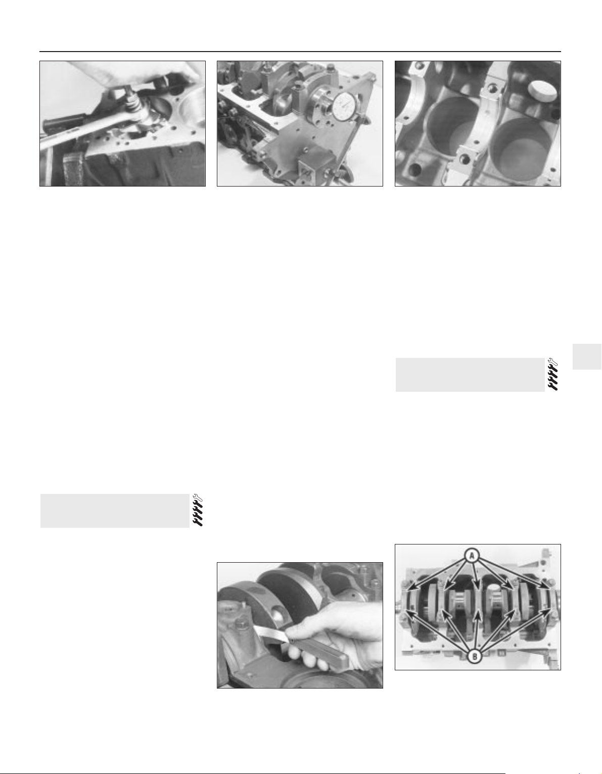
remove the piston/connecting rod assemblies
may result in piston ring breakage.
7 Slacken each of the big-end bearing cap
bolts half a turn at a time, until they can be
removed by hand. Remove the No 1 cap and
bearing shell. Don’t drop the shell out of the
cap.
8 Remove the upper bearing shell, and push
the connecting rod/piston assembly out
through the top of the engine. Use a wooden
hammer handle to push on the connecting
rod’s bearing recess. If resistance is felt,
double-check that all of the ridge was
removed from the cylinder.
9 Repeat the procedure for the remaining
cylinders.
10 After removal, reassemble the big-end
bearing caps and shells on their respective
connecting rods, and refit the bolts fingertight. Leaving the old shells in place until
reassembly will help prevent the bearing
recesses from being accidentally nicked or
gouged. New shells should be used on
reassembly.
11 Don’t attempt to separate the pistons
from the connecting rods - see Section 12.
Note: The crankshaft can be removed only
after the engine/transmission has been
removed from the vehicle. It is assumed that
the transmission and flywheel/driveplate,
timing belt, cylinder head, sump, oil pump
pick-up/strainer pipe and oil baffle, oil pump,
and piston/connecting rod assemblies, have
already been removed. The crankshaft lefthand oil seal carrier must be unbolted from
the cylinder block/crankcase before
proceeding with crankshaft removal.
1 Before the crankshaft is removed, check
the endfloat. Mount a DTI (Dial Test Indicator,
or dial gauge) with the stem in line with the
crankshaft and just touching the crankshaft
(see illustration).
2 Push the crankshaft fully away from the
gauge, and zero it. Next, lever the crankshaft
towards the gauge as far as possible, and
check the reading obtained. The distance that
the crankshaft moved is its endfloat; if it is
greater than specified, check the crankshaft
thrust surfaces for wear. If no wear is evident,
new thrustwashers should correct the
endfloat; these are part of the No 3 (centre)
main bearing upper shell (see illustration).
3 If no dial gauge is available, feeler gauges
can be used. Gently lever or push the
crankshaft all the way towards the right-hand
end of the engine. Slip feeler gauges between
the crankshaft and the right-hand face of the
No 3 (centre) main bearing to determine the
clearance (see illustration).
4 Check the main bearing caps, to see if they
are marked to indicate their locations (see
illustration). They should be numbered
consecutively from the timing belt end of the
engine - if not, mark them with numberstamping dies or a centre-punch. The caps will
also have an embossed arrow pointing to the
timing belt end of the engine. Noting the
different fasteners (for the oil baffle nuts) used on
caps 2 and 4, slacken the cap bolts a quarterturn at a time each, starting with the left- and
right-hand end caps and working toward the
centre, until they can be removed by hand.
5 Gently tap the caps with a soft-faced
hammer, then separate them from the cylinder
block/crankcase. If necessary, use the bolts
as levers to remove the caps. Try not to drop
the bearing shells if they come out with the
caps.
6 Carefully lift the crankshaft out of the
engine. It may be a good idea to have an
assistant available, since the crankshaft is
quite heavy. With the bearing shells in place in
the cylinder block/crankcase and main
bearing caps, return the caps to their
respective locations on the block, and tighten
the bolts finger-tight. Leaving the old shells in
place until reassembly will help prevent the
bearing recesses from being accidentally
nicked or gouged. New shells should be used
on reassembly.
Note: Always check first what replacement
parts are available before planning any
overhaul operation; refer to Section 1 of this
Part. A Ford dealer, or a good engine
reconditioning specialist/automotive parts
supplier may be able to suggest alternatives
which will enable you to overcome the lack of
replacement parts.
Cleaning
1 For complete cleaning, remove the water
pump, all external components, and all
electrical switches/sensors. Unbolt the
piston-cooling oil jets or blanking plugs (as
11 Cylinder block/crankcase -
cleaning and inspection
10 Crankshaft - removal
Engine removal and general engine overhaul procedures 2B•13
2B
10.3 Checking crankshaft endfloat with a
feeler gauge
10.4 Before unbolting crankshaft main
bearing caps, note arrows pointing to timing
belt end of engine (A), and bearing numbers
(B) consecutive from timing belt end
9.6 A ridge reamer may be required, to
remove the ridge from the top of each
cylinder - do this before removing the
pistons!
10.1 Checking crankshaft endfloat with a
dial gauge
10.2 Thrustwashers integral with No 3
(centre) main bearing upper shell control
crankshaft endfloat
Page 80
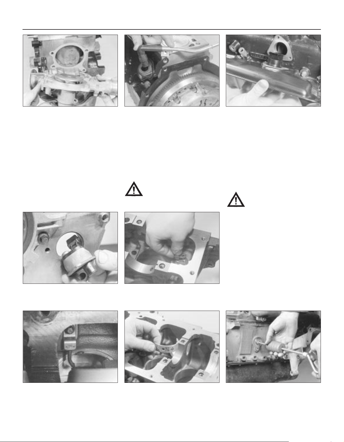
applicable); note that Ford state that the
piston-cooling oil jets (where fitted) must be
renewed whenever the engine is dismantled
for full overhaul (see illustrations).
2 Remove the main bearing caps, and
separate the bearing shells from the caps and
the cylinder block/crankcase. Mark or label
the shells, indicating which bearing they were
removed from, and whether they were in the
cap or the block, then set them aside (see
illustration). Wipe clean the block and cap
bearing recesses, and inspect them for nicks,
gouges and scratches.
3 Scrape all traces of gasket from the cylinder
block/crankcase, taking care not to damage
the sealing surfaces.
4 Remove all oil gallery plugs (where fitted).
The plugs are usually very tight - they may
have to be drilled out and the holes re-tapped.
Use new plugs when the engine is
reassembled. Drill a small hole in the centre of
each core plug, and pull them out with a car
bodywork dent puller (see illustration).
Caution: The core plugs (also
known as freeze or soft plugs)
may be difficult or impossible to
retrieve if they are driven into the
block coolant passages.
5 If any of the castings are extremely dirty, all
should be steam-cleaned.
6 After the castings are returned from steamcleaning, clean all oil holes and oil galleries
one more time. Flush all internal passages
with warm water until the water runs clear,
then dry thoroughly, and apply a light film of
oil to all machined surfaces, to prevent
rusting. If you have access to compressed air,
use it to speed the drying process, and to
blow out all the oil holes and galleries.
Warning: Wear eye protection
when using compressed air!
7 If the castings are not very dirty, you can do
an adequate cleaning job with hot soapy
water (as hot as you can stand!) and a stiff
brush. Take plenty of time, and do a thorough
job. Regardless of the cleaning method used,
be sure to clean all oil holes and galleries very
thoroughly, and to dry all components
completely; protect the machined surfaces as
described above, to prevent rusting.
8 All threaded holes must be clean and dry,
to ensure accurate torque readings during
reassembly; now is also a good time to clean
and check the threads of all principal bolts however, note that some, such as the cylinder
head and flywheel/driveplate bolts, are to be
renewed as a matter of course whenever they
are disturbed. Run the proper-size tap into
2B•14 Engine removal and general engine overhaul procedures
11.1A Remove water pump . . . 11.1B . . . crankcase breather pipe and
PCV valve . . .
11.1C . . . unbolt crankcase ventilation
system oil separator . . .
11.1F . . . but note that piston-cooling oil
jets (where fitted) must be renewed as a
matter of course whenever engine is
overhauled
11.2 Felt marker pens can be used as
shown to identify bearing shells without
damaging them
11.1D . . . remove electrical
switches/sensors such as crankshaft
speed/position sensor . . .
11.1E . . . unbolt blanking plugs (where
fitted) to clean out oilways . . .
11.4 The core plugs should be removed
with a puller - if they’re driven into the
block, they may be impossible to
retrieve
Page 81
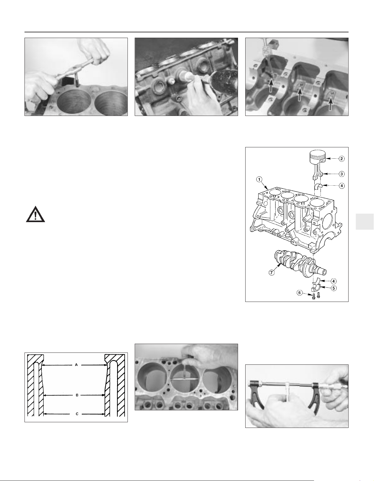
each of the holes, to remove rust, corrosion,
thread sealant or sludge, and to restore
damaged threads (see illustration). If
possible, use compressed air to clear the
holes of debris produced by this operation; a
good alternative is to inject aerosol-applied
water-dispersant lubricant into each hole,
using the long spout usually supplied.
Warning: Wear eye protection
when cleaning out these holes in
this way, and be sure to dry out
any excess liquid left in the holes.
9 When all inspection and repair procedures
are complete (see below) and the block is
ready for reassembly, apply suitable sealant
to the new oil gallery plugs, and insert them
into the holes in the block. Tighten them
securely. After coating the sealing surfaces of
the new core plugs with suitable sealant,
install them in the cylinder block/crankcase
(see illustration). Make sure they are driven
in straight and seated properly, or leakage
could result. Special tools are available for
this purpose, but a large socket with an
outside diameter that will just slip into the
core plug, used with an extension and
hammer, will work just as well.
10 Refit the blanking plugs or (new) pistoncooling oil jets (as applicable), tightening their
Torx screws to the torque wrench setting
specified (see illustration). Refit also all other
external components removed, referring to
the relevant Chapter of this manual for further
details where required. Refit the main bearing
caps, and tighten the bolts finger-tight.
11 If the engine is not going to be
reassembled right away, cover it with a large
plastic bag to keep it clean; protect the
machined surfaces as described above, to
prevent rusting.
Inspection
12 Visually check the castings for cracks and
corrosion. Look for stripped threads in the
threaded holes. If there has been any history
of internal coolant leakage, it may be
worthwhile having an engine overhaul
specialist check the cylinder block/crankcase
for cracks with special equipment. If defects
are found, have them repaired, if possible, or
renew the assembly (see illustration).
13 Check each cylinder bore for scuffing and
scoring.
14 Noting that the cylinder bores must be
measured with all the crankshaft main bearing
caps bolted in place (without the crankshaft
and bearing shells), to the specified torque
wrench settings, measure the diameter of
each cylinder at the top (just under the ridge
area), centre and bottom of the cylinder bore,
parallel to the crankshaft axis. Next, measure
each cylinder’s diameter at the same three
locations across the crankshaft axis (see
illustrations). Note the measurements
obtained.
Engine removal and general engine overhaul procedures 2B•15
2B
11.12 Cylinder block, piston/connecting
rod and crankshaft details
1 Cylinder block/crankcase
2 Piston
3 Connecting rod
4 Big-end bearing shell
5 Big-end bearing cap
6 Big-end bearing cap bolts
7 Crankshaft
11.14A Measure the diameter of each
cylinder just under the wear ridge (A), at
the centre (B) and at the bottom (C)
11.14B The ability to “feel” when the
telescoping gauge is at the correct point will
be developed over time, so work slowly, and
repeat the check until you’re satisfied that
the bore measurement is accurate
11.8 All bolt holes in the block -
particularly the main bearing cap and head
bolt holes - should be cleaned and
restored with a tap (be sure to remove
debris from the holes after this is done)
11.9 A large socket on an extension can
be used to drive the new core plugs into
their bores
11.10 Do not forget to refit all components
- such as oilway blanking plugs (three of
four arrowed) - tighten fasteners to torque
wrench settings specified
11.14C The gauge is then measured with a
micrometer to determine the bore size
Page 82
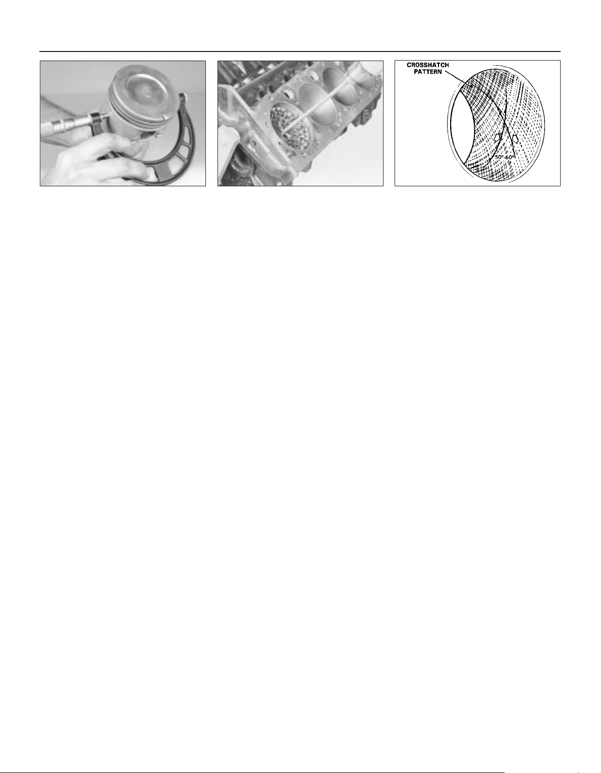
15 Measure the piston diameter at right-
angles to the gudgeon pin axis, just above the
bottom of the skirt; again, note the results
(see illustration).
16 If it is wished to obtain the piston-to-bore
clearance, measure the bore and piston skirt
as described above, and subtract the skirt
diameter from the bore measurement. If the
precision measuring tools shown are not
available, the condition of the pistons and
bores can be assessed, though not quite as
accurately, by using feeler gauges as follows.
Select a feeler gauge of thickness equal to the
specified piston-to-bore clearance, and slip it
into the cylinder along with the matching
piston. The piston must be positioned exactly
as it normally would be. The feeler gauge
must be between the piston and cylinder on
one of the thrust faces (at right-angles to the
gudgeon pin bore). The piston should slip
through the cylinder (with the feeler gauge in
place) with moderate pressure; if it falls
through or slides through easily, the clearance
is excessive, and a new piston will be
required. If the piston binds at the lower end
of the cylinder, and is loose toward the top,
the cylinder is tapered. If tight spots are
encountered as the piston/feeler gauge is
rotated in the cylinder, the cylinder is out-ofround (oval).
17 Repeat these procedures for the
remaining pistons and cylinder bores.
18 Compare the results with the
Specifications at the beginning of this
Chapter; if any measurement is beyond the
dimensions specified for that class (check the
piston crown marking to establish the class of
piston fitted), or if any bore measurement is
significantly different from the others
(indicating that the bore is tapered or oval),
the piston or bore is excessively-worn.
19 Worn pistons must be renewed; at the
time of writing, pistons are available as Ford
replacement parts only as part of the
complete piston/connecting rod assembly.
See a Ford dealer or engine reconditioning
specialist for advice.
20 If any of the cylinder bores are badly
scuffed or scored, or if they are excessivelyworn, out-of-round or tapered, the usual
course of action would be to have the cylinder
block/crankcase rebored, and to fit new,
oversized, pistons on reassembly. See a Ford
dealer or engine reconditioning specialist for
advice.
21 If the bores are in reasonably good
condition and not excessively-worn, then it
may only be necessary to renew the piston
rings.
22 If this is the case (and if new rings can be
found), the bores should be honed, to allow
the new rings to bed in correctly and provide
the best possible seal; before honing the
bores, refit the main bearing caps (without the
bearing shells), and tighten the bolts to the
specified torque wrench setting. Note: If you
don’t have the tools, or don’t want to tackle
the honing operation, most engine
reconditioning specialists will do it for a
reasonable fee.
23 Two types of cylinder hones are
commonly available - the flex hone or “bottlebrush” type, and the more traditional
surfacing hone with spring-loaded stones.
Both will do the job and are used with a
power drill, but for the less-experienced
mechanic, the “bottle-brush” hone will
probably be easier to use. You will also need
some paraffin or honing oil, and rags.
Proceed as follows:
(a) Mount the hone in the drill, compress the
stones, and slip it into the first bore (see
illustration). Be sure to wear safety
goggles or a face shield!
(b) Lubricate the bore with plenty of honing
oil, switch on the drill, and move the hone
up and down the bore, at a pace that will
produce a fine cross-hatch pattern on the
cylinder walls. Ideally, the cross-hatch
lines should intersect at approximately a
60° angle (see illustration). Be sure to
use plenty of lubricant, and don’t take off
any more material than is absolutely
necessary to produce the desired finish.
Note: Piston ring manufacturers may
specify a different crosshatch angle - read
and follow any instructions included with
the new rings.
(c) Don’t withdraw the hone from the bore
while it’s running. Instead, switch off the
drill, and continue moving the hone up
and down the bore until it comes to a
complete stop, then compress the stones
and withdraw the hone. If you’re using a
“bottle-brush” hone, switch off the drill,
then turn the chuck in the normal
direction of rotation while withdrawing the
hone from the bore.
(d) Wipe the oil out of the bore, and repeat
the procedure for the remaining cylinders.
(e) When all the cylinder bores are honed,
chamfer the top edges of the bores with a
small file, so the rings won’t catch when
the pistons are installed. Be very careful
not to nick the cylinder walls with the end
of the file.
(f) The entire cylinder block/crankcase must
be washed very thoroughly with warm,
soapy water, to remove all traces of the
abrasive grit produced during the honing
operation. Note: The bores can be
considered clean when a lint-free white
cloth - dampened with clean engine oil used to wipe them out doesn’t pick up
any more honing residue, which will show
up as grey areas on the cloth. Be sure to
run a brush through all oil holes and
galleries, and flush them with running
water.
(g) When the cylinder block/crankcase is
completely clean, rinse it thoroughly and
dry it, then lightly oil all exposed
machined surfaces, to prevent rusting.
24 The cylinder block/crankcase should now
be completely clean and dry, with all
components checked for wear or damage,
and repaired or overhauled as necessary.
Refit as many ancillary components as
possible, for safekeeping (see paragraphs 9
and 10 above). If reassembly is not to start
immediately, cover the block with a large
plastic bag to keep it clean, and protect the
machined surfaces as described above to
prevent rusting.
2B•16 Engine removal and general engine overhaul procedures
11.15 Measure the piston skirt diameter at
right-angles to the gudgeon pin axis, just
above the base of the skirt
11.23A A “bottle-brush” hone will produce
better results if you have never honed
cylinders before
11.23B The cylinder hone should leave a
smooth, cross-hatch pattern with the lines
intersecting at approximately a 60º angle
Page 83
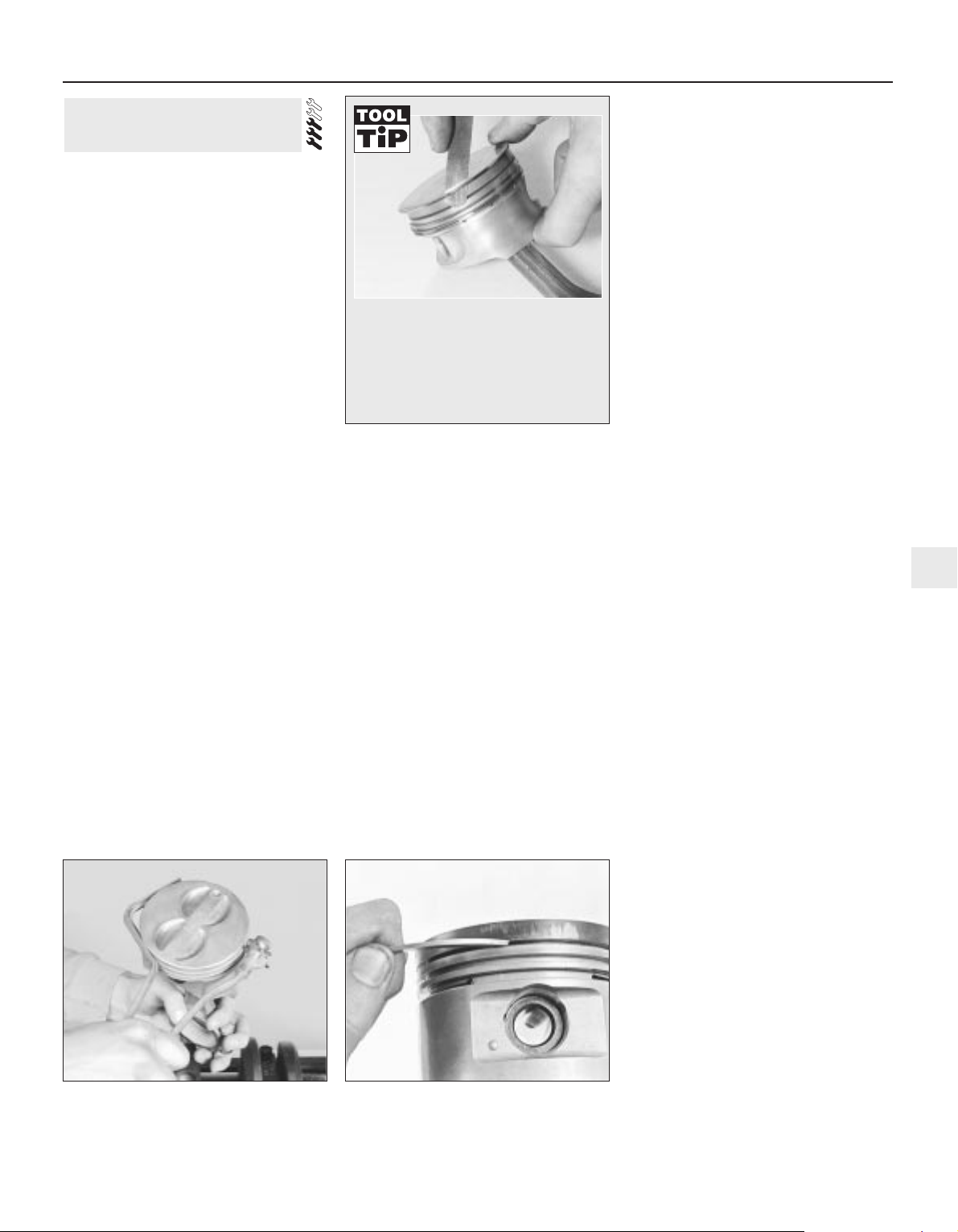
Note: Always check first what replacement
parts are available before planning any
overhaul operation; refer to Section 1 of this
Part. A Ford dealer, or a good engine
reconditioning specialist/automotive parts
supplier may be able to suggest alternatives
which will enable you to overcome the lack of
replacement parts.
1 Before the inspection process can be
carried out, the piston/connecting rod
assemblies must be cleaned, and the original
piston rings removed from the pistons. The
rings should have smooth, polished working
surfaces, with no dull or carbon-coated
sections (showing that the ring is not sealing
correctly against the bore wall, so allowing
combustion gases to blow by) and no traces
of wear on their top and bottom surfaces. The
end gaps should be clear of carbon, but not
polished (indicating a too-small end gap), and
all the rings (including the elements of the oil
control ring) should be free to rotate in their
grooves, but without excessive up-and-down
movement. If the rings appear to be in good
condition, they are probably fit for further use;
check the end gaps (in an unworn part of the
bore) as described in Section 16. If any of the
rings appears to be worn or damaged, or has
an end gap significantly different from the
specified value, the usual course of action is
to renew all of them as a set. Note: While it is
usual always to renew piston rings when an
engine is overhauled, this of course assumes
that rings are available separately - if not, it
follows that great care must be taken not to
break or damage any of the rings during the
following procedures, and to ensure that each
ring is marked on removal so that it is refitted
only the original way up, and only to the same
groove.
2 Using a piston ring renoval tool, carefully
remove the rings from the pistons. Be careful
not to nick or gouge the pistons in the
process, and mark or label each ring as it is
removed, so that its original top surface can
be identified on reassembly, and so that it can
be returned to its original groove. Take care
also with your hands - piston rings are sharp!
3 Scrape all traces of carbon from the top of
the piston. A hand-held wire brush or a piece
of fine emery cloth can be used, once the
majority of the deposits have been scraped
away. Do not, under any circumstances, use a
wire brush mounted in a drill motor to remove
deposits from the pistons - the piston material
is soft, and may be eroded away by the wire
brush.
4 Use a piston ring groove-cleaning tool to
remove carbon deposits from the ring
grooves. If a tool isn’t available, but
replacement rings have been found, a piece
broken off the old ring will do the job. Be very
careful to remove only the carbon deposits don’t remove any metal, and do not nick or
scratch the sides of the ring grooves (see
illustrations). Protect your fingers - piston
rings are sharp!
5 Once the deposits have been removed,
clean the piston/rod assemblies with solvent,
and dry them with compressed air (if
available). Make sure the oil return holes in the
back sides of the ring grooves, and the oil
hole in the lower end of each rod, are clear.
6 If the pistons and cylinder walls aren’t
damaged or worn excessively - refer to
Section 11 for details of inspection and
measurement procedures - and if the cylinder
block/crankcase is not rebored, new pistons
won’t be necessary. Normal piston wear
appears as even vertical wear on the piston
thrust surfaces, and slight looseness of the
top ring in its groove.
7 Carefully inspect each piston for cracks
around the skirt, at the pin bosses, and at the
ring lands (between the ring grooves).
8 Look for scoring and scuffing on the thrust
faces of the skirt, holes in the piston crown,
and burned areas at the edge of the crown. If
the skirt is scored or scuffed, the engine may
have been suffering from overheating and/or
abnormal combustion, which caused
excessively-high operating temperatures. The
cooling and lubrication systems should be
checked thoroughly. A hole in the piston
crown is an indication that abnormal
combustion (pre-ignition) was occurring.
Burned areas at the edge of the piston crown
are usually evidence of spark knock
(detonation). If any of the above problems
exist, the causes must be corrected, or the
damage will occur again. The causes may
include intake air leaks, incorrect fuel/air
mixture, incorrect ignition timing, or EGR
system malfunctions.
9 Corrosion of the piston, in the form of small
pits, indicates that coolant is leaking into the
combustion chamber and/or the crankcase.
Again, the cause must be corrected, or the
problem may persist in the rebuilt engine.
10 Check the piston-to-rod clearance by
twisting the piston and rod in opposite
directions. Any noticeable play indicates
excessive wear, which must be corrected. The
piston/connecting rod assemblies should be
taken to a Ford dealer or engine reconditioning specialist to have the pistons, gudgeon
pins and rods checked, and new components
fitted as required.
11 Don’t attempt to separate the pistons
from the connecting rods (even if non-genuine
replacements are found elsewhere). This is a
task for a Ford dealer or similar engine
reconditioning specialist, due to the special
heating equipment, press, mandrels and
supports required to do the job. If the
piston/connecting rod assemblies do require
this sort of work, have the connecting rods
checked for bend and twist, since only such
engine repair specialists will have the facilities
for this purpose.
12 Check the connecting rods for cracks and
other damage. Temporarily remove the bigend bearing caps and the old bearing shells,
wipe clean the rod and cap bearing recesses,
and inspect them for nicks, gouges and
scratches. After checking the rods, replace
the old shells, slip the caps into place, and
tighten the bolts finger-tight.
12 Piston/connecting rod
assemblies - inspection
Engine removal and general engine overhaul procedures 2B•17
2B
12.4A The piston ring grooves can be
cleaned with a special tool, as shown
here . . .
12.4B . . . or a section of a broken ring, if
available
If a piston ring removal tool is not
available, the rings can be removed by
hand, expanding them over the top of
the pistons. The use of two or three old
feeler blades will be helpful in
preventing the rings dropping into
empty grooves.
Page 84
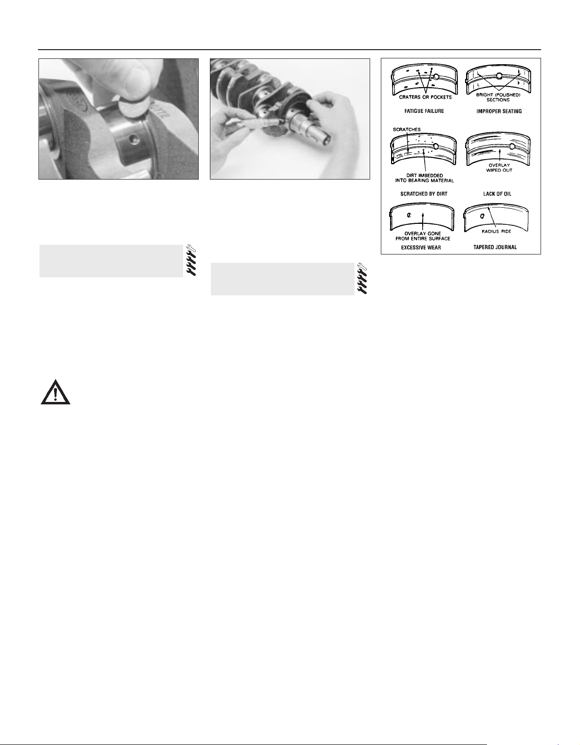
Note: Always check first what replacement
parts are available before planning any
overhaul operation; refer to Section 1 of this
Part. A Ford dealer, or a good engine
reconditioning specialist/automotive parts
supplier, may be able to suggest alternatives
which will enable you to overcome the lack of
replacement parts.
1 Clean the crankshaft, and dry it with
compressed air if available.
Warning: Wear eye protection
when using compressed air! Be
sure to clean the oil holes with a
pipe cleaner or similar probe.
2 Check the main and crankpin (big-end)
bearing journals for uneven wear, scoring,
pitting and cracking.
3 Rub a penny across each journal several
times (see illustration). If a journal picks up
copper from the penny, it is too rough.
4 Remove all burrs from the crankshaft oil
holes with a stone, file or scraper.
5 Using a micrometer, measure the diameter
of the main bearing and crankpin (big-end)
journals, and compare the results with the
Specifications at the beginning of this Chapter
(see illustration).
6 By measuring the diameter at a number of
points around each journal’s circumference,
you will be able to determine whether or not
the journal is out-of-round. Take the
measurement at each end of the journal, near
the webs, to determine if the journal is
tapered.
7 If the crankshaft journals are damaged,
tapered, out-of-round, or worn beyond the
limits specified in this Chapter, the crankshaft
must be taken to an engine overhaul
specialist, who will regrind it, and who can
supply the necessary undersize bearing
shells.
8 Check the oil seal journals at each end of
the crankshaft for wear and damage. If either
seal has worn an excessive groove in its
journal, consult an engine overhaul specialist,
who will be able to advise whether a repair is
possible, or whether a new crankshaft is
necessary.
Note: Always check first what replacement
parts are available before planning any
overhaul operation; refer to Section 1 of this
Part. A Ford dealer, or a good engine
reconditioning specialist/automotive parts
supplier, may be able to suggest alternatives
which will enable you to overcome the lack of
replacement parts.
1 Even though the main and big-end bearing
shells should be renewed during the engine
overhaul, the old shells should be retained for
close examination, as they may reveal
valuable information about the condition of
the engine (see illustration).
2 Bearing failure occurs because of lack of
lubrication, the presence of dirt or other
foreign particles, overloading the engine, and
corrosion. Regardless of the cause of bearing
failure, it must be corrected before the engine
is reassembled, to prevent it from happening
again.
3 When examining the bearing shells, remove
them from the cylinder block/crankcase and
main bearing caps, and from the connecting
rods and the big-end bearing caps, then lay
them out on a clean surface in the same
general position as their location in the
engine. This will enable you to match any
bearing problems with the corresponding
crankshaft journal. Do not touch any shell’s
bearing surface with your fingers while
checking it, or the delicate surface may be
scratched.
4 Dirt or other foreign matter gets into the
engine in a variety of ways. It may be left in
the engine during assembly, or it may pass
through filters or the crankcase ventilation
system. It may get into the oil, and from there
into the bearings. Metal chips from machining
operations and normal engine wear are often
present. Abrasives are sometimes left in
engine components after reconditioning,
especially when parts are not thoroughly
cleaned using the proper cleaning methods.
Whatever the source, these foreign objects
often end up embedded in the soft bearing
material, and are easily recognized. Large
particles will not embed in the material, and
will score or gouge the shell and journal. The
best prevention for this cause of bearing
failure is to clean all parts thoroughly, and to
keep everything spotlessly-clean during
engine assembly. Frequent and regular engine
oil and filter changes are also recommended.
5 Lack of lubrication (or lubrication
breakdown) has a number of inter-related
causes. Excessive heat (which thins the oil),
overloading (which squeezes the oil from the
bearing face) and oil leakage (from excessive
bearing clearances, worn oil pump or high
engine speeds) all contribute to lubrication
breakdown. Blocked oil passages, which
usually are the result of misaligned oil holes in
a bearing shell, will also starve a bearing of oil,
and destroy it. When lack of lubrication is the
cause of bearing failure, the bearing material
is wiped or extruded from the shell’s steel
backing. Temperatures may increase to the
point where the steel backing turns blue from
overheating.
6 Driving habits can have a definite effect on
bearing life. Full-throttle, low-speed operation
(labouring the engine) puts very high loads on
bearings, which tends to squeeze out the oil
film. These loads cause the shells to flex,
which produces fine cracks in the bearing
face (fatigue failure). Eventually, the bearing
material will loosen in pieces, and tear away
from the steel backing. Short-distance driving
leads to corrosion of bearings, because
insufficient engine heat is produced to drive
off condensed water and corrosive gases.
These products collect in the engine oil,
forming acid and sludge. As the oil is carried
14 Main and big-end bearings -
inspection
13 Crankshaft - inspection
2B•18 Engine removal and general engine overhaul procedures
13.3 Rubbing a penny lengthwise along
each journal will reveal its condition - if
copper rubs off and is embedded in the
crankshaft, the journals should be
reground
13.5 Measure the diameter of each
crankshaft journal at several points, to
detect taper and out-of-round conditions
14.1 When inspecting the main and bigend bearings, look for these problems
Page 85
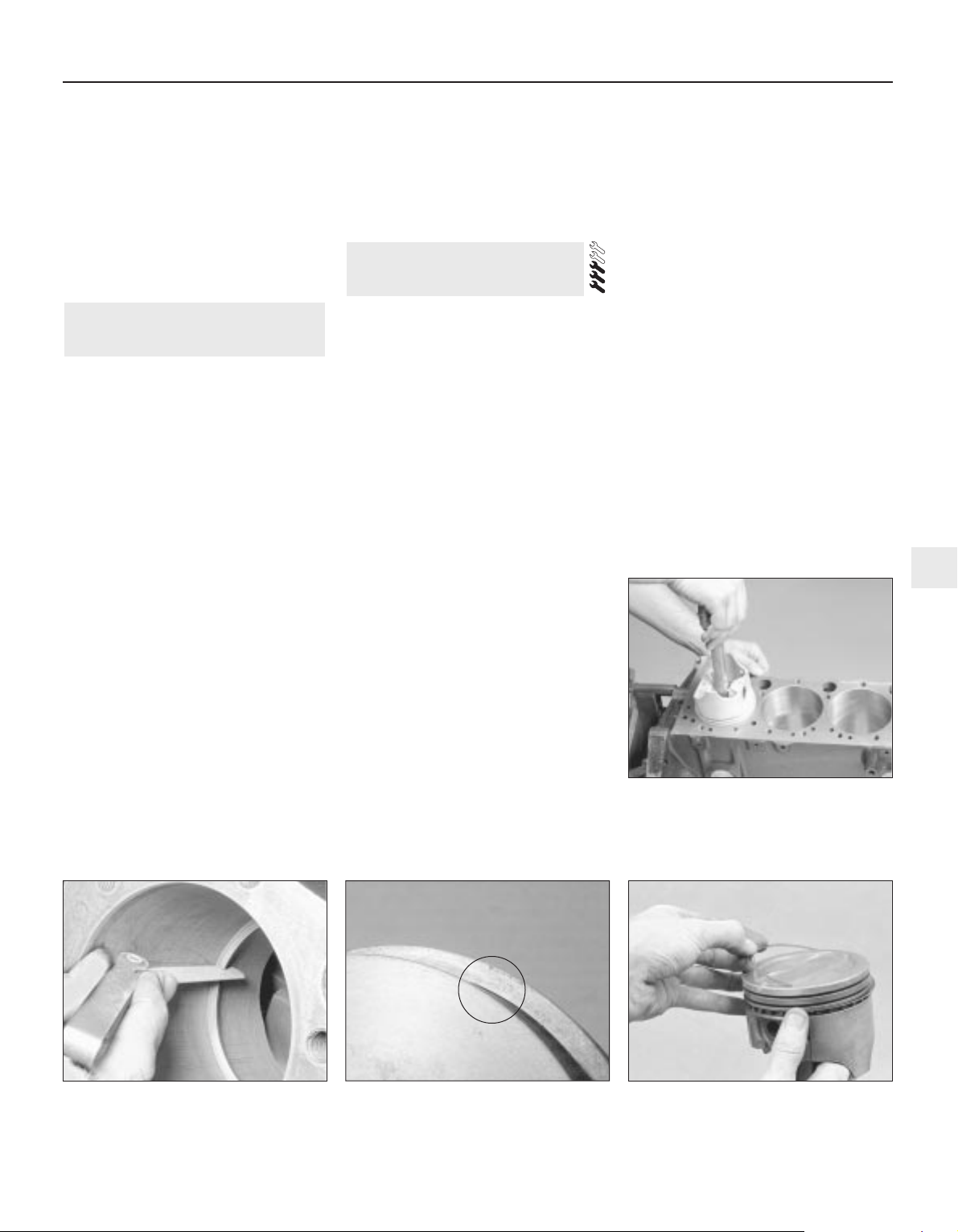
to the engine bearings, the acid attacks and
corrodes the bearing material.
7 Incorrect shell refitting during engine
assembly will lead to bearing failure as well.
Tight-fitting shells leave insufficient bearing
running clearance, and will result in oil
starvation. Dirt or foreign particles trapped
behind a bearing shell result in high spots on
the bearing, which lead to failure. Do not
touch any shell’s bearing surface with your
fingers during reassembly; there is a risk of
scratching the delicate surface, or of
depositing particles of dirt on it.
1 Before reassembly begins, ensure that all
new parts have been obtained, and that all
necessary tools are available. Read through
the entire procedure, to familiarise yourself
with the work involved, and to ensure that all
items necessary for reassembly of the engine
are at hand. In addition to all normal tools and
materials, suitable sealant will be required for
two of the joint faces (Ford recommend
Hylosil 102 for the cylinder block/crankcaseto-sump/oil pump/oil seal carrier joints, and
Loctite 518 for the camshaft right-hand
bearing caps). In all other cases, provided the
relevant mating surfaces are clean and flat,
new gaskets will be sufficient to ensure joints
are oil-tight. Do not use any kind of siliconebased sealant on any part of the fuel system
or inlet manifold, and never use exhaust
sealants upstream of the catalytic converter.
2 In order to save time and avoid problems,
engine reassembly can be carried out in the
following order:
(a) Crankshaft (Section 17).
(b) Piston/connecting rod assemblies
(Section 18).
(c) Oil pump (Part A of this Chapter, Section
16).
(d) Sump (Part A of this Chapter, Section 15).
(e) Flywheel/driveplate (Part A of this
Chapter, Section 21).
(f) Cylinder head (Part A of this Chapter,
Section 14).
(g) Timing belt inner cover, tensioner and
toothed pulleys, and timing belt (Part A of
this Chapter).
(h) Engine external components.
3 At this stage, all engine components should
be absolutely clean and dry, with all faults
repaired; they should be laid out (or in
individual containers) on a completely-clean
work surface.
1 Before installing new piston rings, check
the end gaps. Lay out each piston set with a
piston/connecting rod assembly, and keep
them together as a matched set from now on.
2 Insert the top compression ring into the first
cylinder, and square it up with the cylinder
walls by pushing it in with the top of the piston
(see illustration). The ring should be near the
bottom of the cylinder, at the lower limit of
ring travel.
3 To measure the end gap, slip feeler gauges
between the ends of the ring, until a gauge
equal to the gap width is found (see
illustration). The feeler gauge should slide
between the ring ends with a slight amount of
drag. Compare the measurement to the value
given in the Specifications Section of this
Chapter; if the gap is larger or smaller than
specified, double-check to make sure you
have the correct rings before proceeding. If
you are assessing the condition of used rings,
have the cylinder bores checked and
measured by a Ford dealer or similar engine
reconditioning specialist, so that you can be
sure of exactly which component is worn, and
seek advice as to the best course of action to
take.
4 If the end gap is still too small, it must be
opened up by careful filing of the ring ends
using a fine file. If it is too large, this is not as
serious, unless the specified limit is exceeded,
in which case very careful checking is
required of the dimensions of all components,
as well as of the new parts.
5 Repeat the procedure for each ring that will
be installed in the first cylinder, and for each
ring in the remaining cylinders. Remember to
keep rings, pistons and cylinders matched up.
6 Refit the piston rings as follows. Where the
original rings are being refitted, use the marks
or notes made on removal, to ensure that
each ring is refitted to its original groove and
the same way up. New rings generally have
their top surfaces identified by markings
(often an indication of size, such as “STD”, or
the word “TOP”) - the rings must be fitted with
such markings uppermost (see illustration).
Note: Always follow the instructions printed
on the ring package or box - different
manufacturers may require different
approaches. Do not mix up the top and
second compression rings, as they usually
have different cross-sections.
7 The oil control ring (lowest one on the
piston) is usually installed first. It is composed
of three separate elements. Slip the
spacer/expander into the groove (see
illustration). If an anti-rotation tang is used,
make sure it is inserted into the drilled hole in
the ring groove. Next, install the lower side
rail. Don’t use a piston ring installation tool on
the oil ring side rails, as they may be
damaged. Instead, place one end of the side
rail into the groove between the
spacer/expander and the ring land, hold it
firmly in place, and slide a finger around the
piston while pushing the rail into the groove
16 Piston rings - refitting
15 Engine overhaul -
reassembly sequence
Engine removal and general engine overhaul procedures 2B•19
2B
16.7A Installing the spacer/expander in
the oil control ring groove
16.2 When checking piston ring end gap,
the ring must be square in the cylinder
bore (this is done by pushing the ring down
with the top of a piston, as shown)
16.3 With the ring square in the bore,
measure the end gap with a feeler
gauge
16.6 Look for etched markings (“STD” indicating a standard-sized ring - shown
here) identifying piston ring top surface
Page 86
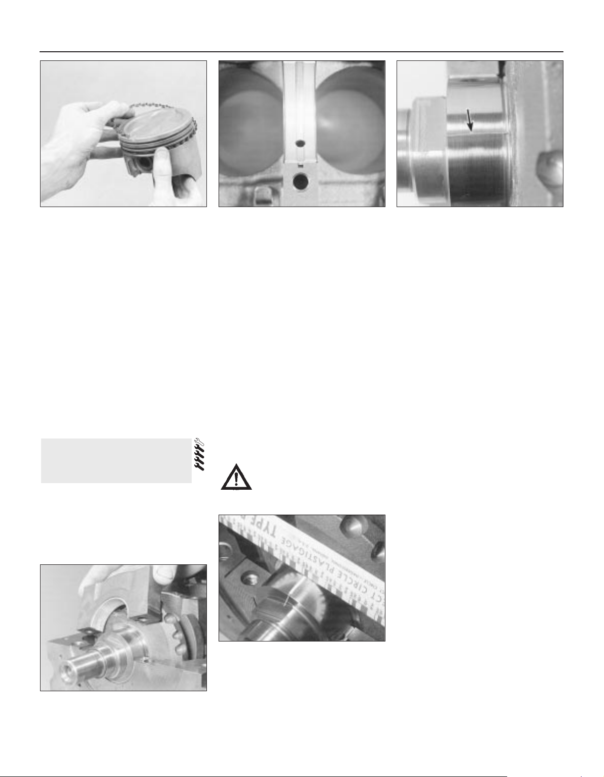
(see illustration). Next, install the upper side
rail in the same manner.
8 After the three oil ring components have
been installed, check that both the upper and
lower side rails can be turned smoothly in the
ring groove.
9 The second compression (middle) ring is
installed next, followed by the top
compression ring - ensure their marks are
uppermost, and be careful not to confuse
them. Don’t expand either ring any more than
necessary to slide it over the top of the piston.
10 With all the rings in position, space the
ring gaps (including the elements of the oil
control ring) uniformly around the piston at
120° intervals. Repeat the procedure for the
remaining pistons and rings.
1 Crankshaft refitting is the first major step in
engine reassembly. It is assumed at this point
that the cylinder block/crankcase and
crankshaft have been cleaned, inspected and
repaired or reconditioned as necessary.
Position the engine upside-down.
2 Remove the main bearing cap bolts, and lift
out the caps. Lay the caps out in the proper
order, to ensure correct installation.
3 If they’re still in place, remove the old
bearing shells from the block and the main
bearing caps. Wipe the bearing recesses of
the block and caps with a clean, lint-free
cloth. They must be kept spotlessly-clean!
Main bearing running clearance
check
4 Clean the backs of the new main bearing
shells. Fit the shells with an oil groove in each
main bearing location in the block; note the
thrustwashers integral with the No 3 (centre)
main bearing upper shell. Fit the other shell
from each bearing set in the corresponding
main bearing cap. Make sure the tab on each
bearing shell fits into the notch in the block or
cap. Also, the oil holes in the block must line
up with the oil holes in the bearing shell (see
illustration).
Caution: Don’t hammer the shells
into place, and don’t nick or gouge
the bearing faces. No lubrication
should be used at this time.
5 Clean the bearing surfaces of the shells in
the block and the crankshaft main bearing
journals with a clean, lint-free cloth. Check or
clean the oil holes in the crankshaft, as any
dirt here can go only one way - straight
through the new bearings.
6 Once you’re certain the crankshaft is clean,
carefully lay it in position in the main bearings.
Trim several pieces of the appropriate-size
Plastigage (they must be slightly shorter than
the width of the main bearings), and place one
piece on each crankshaft main bearing
journal, parallel with the crankshaft centre-line
(see illustration).
7 Clean the bearing surfaces of the cap
shells, and install the caps in their respective
positions (don’t mix them up) with the arrows
pointing to the timing belt end of the engine.
Don’t disturb the Plastigage (see illustration).
8 Working on one cap at a time, from the
centre main bearing outwards (and ensuring
that each cap is tightened down squarely and
evenly onto the block), tighten the main
bearing cap bolts to the specified torque
wrench setting. Don’t rotate the crankshaft at
any time during this operation!
9 Remove the bolts, and carefully lift off the
main bearing caps. Keep them in order. Don’t
disturb the Plastigage or rotate the
crankshaft. If any of the main bearing caps are
difficult to remove, tap them gently from sideto-side with a soft-faced mallet to loosen
them.
10 Compare the width of the crushed
Plastigage on each journal with the scale
printed on the Plastigage envelope to obtain
the main bearing running clearance (see
illustration). Check the Specifications to
make sure that the clearance is correct.
11 If the clearance is not as specified, seek
the advice of a Ford dealer or similar engine
reconditioning specialist - if the crankshaft
journals are in good condition (see Section 13), it may be possible simply to renew
the shells to achieve the correct clearance. If
this is not possible, the crankshaft must be
reground by a specialist who can supply the
necessary undersized shells. First though,
17 Crankshaft -
refitting and main bearing
running clearance check
2B•20 Engine removal and general engine overhaul procedures
16.7B DO NOT use a piston ring
installation tool when installing the oil ring
side rails
17.4 Tab on each bearing shell must
engage with notch in block or cap, and oil
holes in upper shells must align with block
oilways
17.6 Lay the Plastigage strips (arrowed) on
the main bearing journals, parallel to the
crankshaft centre-line
17.7 Refit the main bearing caps and
tighten the bolts as specified
17.10 Compare the width of the crushed
Plastigage to the scale on the envelope to
determine the main bearing oil clearance
(always take the measurement at the
widest point of the Plastigage). Be sure to
use the correct scale; Imperial and metric
scales are included
Page 87
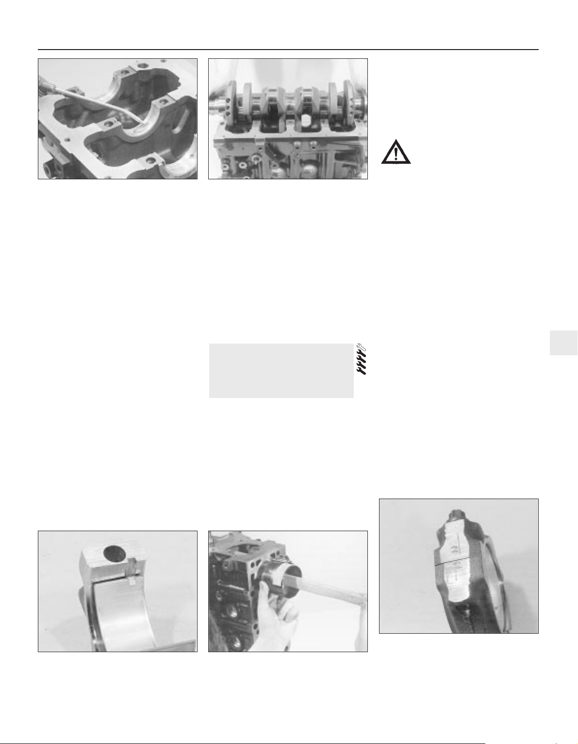
make sure that no dirt or oil was between the
bearing shells and the caps or block when the
clearance was measured. If the Plastigage is
noticeably wider at one end than the other,
the journal may be tapered (see Section 13).
12 Carefully scrape all traces of the
Plastigage material off the main bearing
journals and the bearing surfaces. Be very
careful not to scratch the bearing - use your
fingernail or the edge of a credit card.
Final refitting
13 Carefully lift the crankshaft out of the
engine. Clean the bearing surfaces of the
shells in the block, then apply a thin, uniform
layer of clean molybdenum disulphide-based
grease, engine assembly lubricant, or clean
engine oil to each surface (see illustration).
Coat the thrustwasher surfaces as well.
14 Lubricate the crankshaft oil seal journals
with molybdenum disulphide-based grease,
engine assembly lubricant, or clean engine oil.
15 Make sure the crankshaft journals are
clean, then lay the crankshaft back in place in
the block (see illustration). Clean the bearing
surfaces of the shells in the caps, then
lubricate them. Install the caps in their
respective positions, with the arrows pointing
to the timing belt end of the engine.
16 Working on one cap at a time, from the
centre main bearing outwards (and ensuring
that each cap is tightened down squarely and
evenly onto the block), tighten the main
bearing cap bolts to the specified torque
wrench setting.
17 Rotate the crankshaft a number of times
by hand, to check for any obvious binding.
18 Check the crankshaft endfloat (see
Section 10). It should be correct if the
crankshaft thrust faces aren’t worn or
damaged, and if the No 3 (centre) main
bearing’s upper shell has been renewed.
19 Refit the crankshaft left-hand oil seal
carrier, and install a new seal (see Part A of
this Chapter, Section 20).
1 Before refitting the piston/connecting rod
assemblies, the cylinder bores must be
perfectly clean, the top edge of each cylinder
must be chamfered, and the crankshaft must
be in place.
2 Remove the big-end bearing cap from No 1
cylinder connecting rod (refer to the marks
noted or made on removal). Remove the
original bearing shells, and wipe the bearing
recesses of the connecting rod and cap with a
clean, lint-free cloth. They must be kept
spotlessly-clean!
Big-end bearing running
clearance check
3 Clean the back of the new upper bearing
shell, fit it to the connecting rod, then fit the
other shell of the bearing set to the big-end
bearing cap. Make sure the tab on each shell
fits into the notch in the rod or cap recess
(see illustration).
Caution: Don’t hammer the shells
into place, and don’t nick or
gouge the bearing face. Don’t
lubricate the bearing at this time.
4 It’s critically important that all mating
surfaces of the bearing components are
perfectly clean and oil-free when they’re
assembled.
5 Position the piston ring gaps as described
in Section 16, lubricate the piston and rings
with clean engine oil, and attach a piston ring
compressor to the piston. Leave the skirt
protruding about a quarter-inch, to guide the
piston into the cylinder bore. The rings must
be compressed until they’re flush with the
piston.
6 Rotate the crankshaft until No 1 crankpin
(big-end) journal is at BDC (Bottom Dead
Centre), and apply a coat of engine oil to the
cylinder walls.
7 Arrange the No 1 piston/connecting rod
assembly so that the arrow on the piston
crown points to the timing belt end of the
engine. The cylinder number (counting from
the timing belt end of the engine) is etched
into the flat-machined surface of the
connecting rod and its cap, and must be
visible from the front (exhaust side) of the
engine (see illustrations 9.5A and 9.5B).
Gently insert the assembly into the No 1
cylinder bore, and rest the bottom edge of the
ring compressor on the engine block.
8 Tap the top edge of the ring compressor to
make sure it’s contacting the block around its
entire circumference.
9 Gently tap on the top of the piston with the
end of a wooden hammer handle (see
illustration), while guiding the connecting
18 Piston/connecting rod
assemblies -
refitting and big-end bearing
running clearance check
Engine removal and general engine overhaul procedures 2B•21
2B
18.3 Tab on each big-end bearing shell
must engage with notch in connecting rod
or cap
18.9 The piston can be driven gently into
the cylinder bore with the end of a wooden
or plastic hammer handle
18.11 The connecting rod and big-end
bearing cap of each assembly must share
the same etched cylinder number, visible
from the same (front/exhaust) side of the
engine
17.13 Ensure bearing shells are absolutely
clean, lubricate liberally . . .
17.15 . . . and refit the crankshaft
Page 88

rod’s big-end onto the crankpin. The piston
rings may try to pop out of the ring
compressor just before entering the cylinder
bore, so keep some pressure on the ring
compressor. Work slowly, and if any
resistance is felt as the piston enters the
cylinder, stop immediately. Find out what’s
binding, and fix it before proceeding. Do not,
for any reason, force the piston into the
cylinder - you might break a ring and/or the
piston.
10 To check the big-end bearing running
clearance, cut a piece of the appropriate-size
Plastigage slightly shorter than the width of
the connecting rod bearing, and lay it in place
on the No 1 crankpin (big-end) journal, parallel
with the crankshaft centre-line (see illustration 17.6).
11 Clean the connecting rod-to-cap mating
surfaces, and refit the big-end bearing cap.
Make sure the etched number on the cap is
on the same side as that on the rod (see
illustration). Tighten the cap bolts evenly first use a torque wrench to tighten the bolts
to the specified (first stage) torque setting,
then use an ordinary socket extension bar
and an angle gauge to tighten the bolts
further through the specified (second stage)
angle. Use a thin-wall socket, to avoid
erroneous torque readings that can result if
the socket is wedged between the cap and
nut. If the socket tends to wedge itself
between the nut and the cap, lift up on it
slightly until it no longer contacts the cap.
Don’t rotate the crankshaft at any time during
this operation!
12 Unscrew the bolts and detach the cap,
being very careful not to disturb the
Plastigage.
13 Compare the width of the crushed
Plastigage to the scale printed on the
Plastigage envelope, to obtain the running
clearance (see illustration 17.10). Compare it
to the Specifications, to make sure the
clearance is correct.
14 If the clearance is not as specified, seek
the advice of a Ford dealer or similar engine
reconditioning specialist - if the crankshaft
journals are in good condition (see Section 13), it may be possible simply to renew
the shells to achieve the correct clearance. If
this is not possible, the crankshaft must be
reground by a specialist, who can also supply
the necessary undersized shells. First though,
make sure that no dirt or oil was trapped
between the bearing shells and the
connecting rod or cap when the clearance
was measured. Also, recheck the crankpin
diameter. If the Plastigage was wider at one
end than the other, the crankpin journal may
be tapered (see Section 13).
15 Carefully scrape all traces of the
Plastigage material off the journal and the
bearing surface. Be very careful not to scratch
the bearing - use your fingernail or the edge of
a credit card.
Final piston/connecting rod
refitting
16 Make sure the bearing surfaces are
perfectly clean, then apply a uniform layer of
clean molybdenum disulphide-based grease,
engine assembly lubricant, or clean engine oil,
to both of them. You’ll have to push the piston
into the cylinder to expose the bearing surface
of the shell in the connecting rod.
17 Slide the connecting rod back into place
on the crankpin (big-end) journal, refit the bigend bearing cap, and then tighten the bolts in
two stages, as described above.
18 Repeat the entire procedure for the
remaining piston/connecting rod assemblies.
19 The important points to remember are:
(a) Keep the backs of the bearing shells and
the recesses of the connecting rods and
caps perfectly clean when assembling
them.
(b) Make sure you have the correct
piston/rod assembly for each cylinder use the etched cylinder numbers to
identify the front-facing side of both the
rod and its cap.
(c) The arrow on the piston crown must face
the timing belt end of the engine.
(d) Lubricate the cylinder bores with clean
engine oil.
(e) Lubricate the bearing surfaces when
refitting the big-end bearing caps after the
running clearance has been checked.
20 After all the piston/connecting rod
assemblies have been properly installed,
rotate the crankshaft a number of times by
hand, to check for any obvious binding.
1 With the engine refitted in the vehicle,
double-check the engine oil and coolant
levels. Make a final check that everything has
been reconnected, and that there are no tools
or rags left in the engine compartment.
2 With the spark plugs removed and the
ignition system disabled by unplugging the
ignition coil’s electrical connector, remove
fuse 14 to disconnect the fuel pump. Turn the
engine on the starter until the oil pressure
warning light goes out.
3 Refit the spark plugs, and connect all the
spark plug (HT) leads (Chapter 1). Reconnect
the ignition coil wiring, refit the fuel pump fuse,
then switch on the ignition and listen for the fuel
pump; it will run for a little longer than usual,
due to the lack of pressure in the system.
4 Start the engine, noting that this also may
take a little longer than usual, due to the fuel
system components being empty.
5 While the engine is idling, check for fuel,
coolant and oil leaks. Don’t be alarmed if
there are some odd smells and smoke from
parts getting hot and burning off oil deposits.
If the hydraulic tappets have been disturbed,
some valve gear noise may be heard at first;
this should disappear as the oil circulates fully
around the engine, and normal pressure is
restored in the tappets.
6 Keep the engine idling until hot water is felt
circulating through the top hose, check that it
idles reasonably smoothly and at the usual
speed, then switch it off.
7 After a few minutes, recheck the oil and
coolant levels, and top-up as necessary
(Chapter 1).
8 If they were tightened as described, there is
no need to re-tighten the cylinder head bolts
once the engine has first run after reassembly
- in fact, Ford state that the bolts must not be
re-tightened.
9 If new components such as pistons, rings
or crankshaft bearings have been fitted, the
engine must be run-in for the first 500 miles
(800 km). Do not operate the engine at fullthrottle, or allow it to labour in any gear during
this period. It is recommended that the oil and
filter be changed at the end of this period.
19 Engine -
initial start-up after overhaul
2B•22 Engine removal and general engine overhaul procedures
Page 89
Chapter 3
Cooling, heating, and air conditioning systems
Air conditioning system - general information
and precautions . . . . . . . . . . . . . . . . . . . . . . . . . . . . . . . . . . . . . . . . 11
Air conditioning system components - removal and refitting . . . . . . 12
Antifreeze - general information . . . . . . . . . . . . . . . . . . . . . . . . . . . . 2
Auxiliary drivebelt check and renewal . . . . . . . . . . . . . See Chapter 1
Coolant level check . . . . . . . . . . . . . . . . . . . . . . . . . . . See Chapter 1
Coolant renewal . . . . . . . . . . . . . . . . . . . . . . . . . . . . . . See Chapter 1
Cooling system checks (coolant leaks,
hose condition) . . . . . . . . . . . . . . . . . . . . . . . . . . . . . See Chapter 1
Cooling system electrical switches and sensors -
testing, removal and refitting . . . . . . . . . . . . . . . . . . . . . . . . . . . . . 6
Cooling system hoses - disconnection and renewal . . . . . . . . . . . . 3
Cooling system servicing (draining, flushing
and refilling) . . . . . . . . . . . . . . . . . . . . . . . . . . . . . . . See Chapter 1
General information . . . . . . . . . . . . . . . . . . . . . . . . . . . . . . . . . . . . . . 1
Heater/air conditioning controls - removal and refitting . . . . . . . . . . 10
Heater/ventilation components - removal and refitting . . . . . . . . . . . 9
Pollen filter renewal . . . . . . . . . . . . . . . . . . . . . . . . . . . See Chapter 1
Radiator and expansion tank - removal, inspection
and refitting . . . . . . . . . . . . . . . . . . . . . . . . . . . . . . . . . . . . . . . . . . . . 7
Radiator electric cooling fan(s) - testing, removal and refitting . . . . . 5
Thermostat - removal, testing and refitting . . . . . . . . . . . . . . . . . . . . 4
Water pump - check, removal and refitting . . . . . . . . . . . . . . . . . . . . 8
Coolant
Mixture type . . . . . . . . . . . . . . . . . . . . . . . . . . . . . . . . . . . . . . . . . . . . . . See Chapter 1
Cooling system capacity . . . . . . . . . . . . . . . . . . . . . . . . . . . . . . . . . . . . . See Chapter 1
System pressure
Pressure test . . . . . . . . . . . . . . . . . . . . . . . . . . . . . . . . . . . . . . . . . . . . . . 1.2 bars - should hold this pressure for at least 10 seconds
Expansion tank filler cap
Pressure rating . . . . . . . . . . . . . . . . . . . . . . . . . . . . . . . . . . . . . . . . . . . . 1.2 bars approximately - see cap for actual value
Thermostat
Starts to open . . . . . . . . . . . . . . . . . . . . . . . . . . . . . . . . . . . . . . . . . . . . . 88°C
Radiator electric cooling fan
Switches on at:
Single-speed fans, two-speed fans - first stage . . . . . . . . . . . . . . . . . 100°C
Two-speed fans - second stage . . . . . . . . . . . . . . . . . . . . . . . . . . . . . 103°C
Switches off at:
Single-speed fans, two-speed fans - first stage . . . . . . . . . . . . . . . . . 93°C
Two-speed fans - second stage . . . . . . . . . . . . . . . . . . . . . . . . . . . . . 100°C
Coolant temperature sensor
Resistance:
At -40°C . . . . . . . . . . . . . . . . . . . . . . . . . . . . . . . . . . . . . . . . . . . . . . . . 860.0 to 900.0 kilohms
At 20°C . . . . . . . . . . . . . . . . . . . . . . . . . . . . . . . . . . . . . . . . . . . . . . . . 35.0 to 40.0 kilohms
At 100°C . . . . . . . . . . . . . . . . . . . . . . . . . . . . . . . . . . . . . . . . . . . . . . . 1.9 to 2.5 kilohms
At 120°C . . . . . . . . . . . . . . . . . . . . . . . . . . . . . . . . . . . . . . . . . . . . . . . 1.0 to 1.3 kilohms
Air conditioning system
Refrigerant . . . . . . . . . . . . . . . . . . . . . . . . . . . . . . . . . . . . . . . . . . . . . . . . R134a
3•1
Easy, suitable for
novice with little
experience
Fairly easy, suitable
for beginner with
some experience
Fairly difficult, suitable
for competent DIY
mechanic
Difficult, suitable for
experienced DIY
mechanic
Very difficult,
suitable for expert DIY
or professional
Degrees of difficulty
Specifications
Contents
3
Page 90
Torque wrench settings Nm lbf ft
Radiator mounting bracket-to-subframe bolts . . . . . . . . . . . . . . . . . . . . 23 17
Fluid cooler pipe unions - automatic transmission . . . . . . . . . . . . . . . . . 23 17
Thermostat housing-to-cylinder head bolts . . . . . . . . . . . . . . . . . . . . . . 20 15
Water outlet-to-thermostat housing bolts . . . . . . . . . . . . . . . . . . . . . . . 8 to 11 6 to 8
Coolant temperature sensor . . . . . . . . . . . . . . . . . . . . . . . . . . . . . . . . . . 23 17
Coolant temperature gauge sender . . . . . . . . . . . . . . . . . . . . . . . . . . . . 8 6
Water pump bolts . . . . . . . . . . . . . . . . . . . . . . . . . . . . . . . . . . . . . . . . . . 18 13
Water pump pulley bolts . . . . . . . . . . . . . . . . . . . . . . . . . . . . . . . . . . . . . See Chapter 2A
Air conditioning compressor mounting bolts . . . . . . . . . . . . . . . . . . . . . 25 18
3•2 Cooling, heating and air conditioning systems
Engine cooling system
All vehicles covered by this manual employ
a pressurised engine cooling system with
thermostatically-controlled coolant circulation. A water pump mounted on the drivebelt
end of the cylinder block/crankcase pumps
coolant through the engine. The coolant flows
around each cylinder and toward the
transmission end of the engine. Cast-in
coolant passages direct coolant around the
inlet and exhaust ports, near the spark
plug areas and close to the exhaust valve
guides.
A wax pellet type thermostat is located in a
housing at the transmission end of the engine.
During warm-up, the closed thermostat
prevents coolant from circulating through the
radiator. Instead, it returns through the
coolant metal pipe running across the front of
the engine to the radiator bottom hose and
the water pump. The supply to the heater is
made from the rear of the thermostat housing.
As the engine nears normal operating
temperature, the thermostat opens and allows
hot coolant to travel through the radiator,
where it is cooled before returning to the
engine.
The cooling system is sealed by a pressuretype filler cap in the expansion tank. The
pressure in the system raises the boiling point
of the coolant, and increases the cooling
efficiency of the radiator. When the engine is
at normal operating temperature, the coolant
expands, and the surplus is displaced into the
expansion tank. When the system cools, the
surplus coolant is automatically drawn back
from the tank into the radiator.
Warning: DO NOT attempt to
remove the expansion tank filler
cap, or to disturb any part of the
cooling system, while it or the
engine is hot, as there is a very great risk
of scalding. If the expansion tank filler cap
must be removed before the engine and
radiator have fully cooled down (even
though this is not recommended) the
pressure in the cooling system must first
be released. Cover the cap with a thick
layer of cloth, to avoid scalding, and slowly
unscrew the filler cap until a hissing sound
can be heard. When the hissing has
stopped, showing that pressure is
released, slowly unscrew the filler cap
further until it can be removed; if more
hissing sounds are heard, wait until they
have stopped before unscrewing the cap
completely. At all times, keep well away
from the filler opening.
Warning: Do not allow antifreeze
to come in contact with your
skin, or with the painted surfaces
of the vehicle. Rinse off spills
immediately with plenty of water. Never
leave antifreeze lying around in an open
container, or in a puddle in the driveway or
on the garage floor. Children and pets are
attracted by its sweet smell, but antifreeze
is fatal if ingested.
Warning: If the engine is hot, the
electric cooling fan may start
rotating even if the engine is not
running, so be careful to keep
hands, hair and loose clothing well clear
when working in the engine compartment.
Heating system
The heating system consists of a blower fan
and heater matrix (radiator) located in the
heater unit, with hoses connecting the heater
matrix to the engine cooling system. Hot
engine coolant is circulated through the
heater matrix. When the heater temperature
control on the facia is operated, a flap door
opens to expose the heater box to the
passenger compartment. When the blower
control is operated, the blower fan forces air
through the unit according to the setting
selected.
Air conditioning system
See Section 11.
Warning: Do not allow antifreeze to come in
contact with your skin, or with the painted
surfaces of the vehicle. Rinse off spills
immediately with plenty of water. Antifreeze is
highly toxic if ingested. Never leave antifreeze
lying around in an open container, or in
puddles on the floor; children and pets are
attracted by its sweet smell, and may drink it.
Check with local authorities about disposing
of used antifreeze - many have collection
centres which will see that antifreeze is
disposed of safely.
The cooling system should be filled with a
water/ethylene glycol-based antifreeze
solution, of a strength which will prevent
freezing down to at least -25°C, or lower if the
local climate requires it. Antifreeze also
provides protection against corrosion, and
increases the coolant boiling point.
The cooling system should be maintained
according to the schedule described in
Chapter 1. If antifreeze is used that is not to
Ford’s specification, old or contaminated
coolant mixtures are likely to cause damage,
and encourage the formation of corrosion and
scale in the system. Use distilled water with
the antifreeze, if available - if not, be sure to
use only soft water. Clean rainwater is
suitable.
Before adding antifreeze, check all hoses
and hose connections, because antifreeze
tends to leak through very small openings.
Engines don’t normally consume coolant, so if
the level goes down, find the cause and
correct it.
The exact mixture of antifreeze-to-water
which you should use depends on the
relative weather conditions. The mixture
should contain at least 40% antifreeze, but
not more than 70%. Consult the mixture
ratio chart on the antifreeze container
before adding coolant. Hydrometers are
available at most automotive accessory
shops to test the coolant. Use antifreeze
which meets the vehicle manufacturer’s
specifications.
Note: Refer to the warnings given in Section 1
of this Chapter before starting work.
1 If the checks described in Chapter 1 reveal
a faulty hose, it must be renewed as follows
(see illustration).
2 First drain the cooling system (see Chap-
ter 1); if the antifreeze is not due for renewal,
the drained coolant may be re-used, if it is
collected in a clean container.
3 To disconnect any hose, use a pair of pliers
to release the spring clamps (or a screwdriver
to slacken screw-type clamps), then move
them along the hose clear of the union.
Carefully work the hose off its stubs. The
hoses can be removed with relative ease
when new - on an older car, they may have
stuck.
3 Cooling system hoses -
disconnection and renewal
2 Antifreeze - general information
1 General information
Page 91
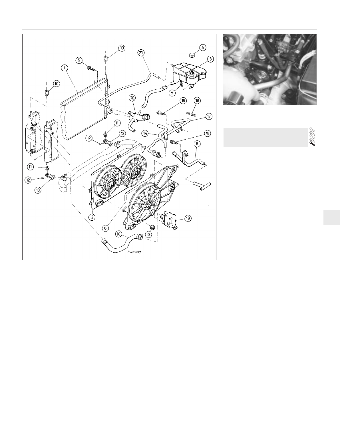
4 If a hose proves stubborn, try to release it
by rotating it on its unions before attempting
to work it off. Gently prise the end of the hose
with a blunt instrument (such as a flat-bladed
screwdriver), but do not apply too much force,
and take care not to damage the pipe stubs or
hoses. Note in particular that the radiator hose
unions are fragile; do not use excessive force
when attempting to remove the hoses. If all
else fails, cut the hose with a sharp knife, then
slit it so that it can be peeled off in two pieces.
While expensive, this is preferable to buying a
new radiator. Check first, however, that a new
hose is readily available.
5 When refitting a hose, first slide the clamps
onto the hose, then work the hose onto its
unions. If the hose is stiff, use soap (or
washing-up liquid) as a lubricant, or soften it
by soaking it in boiling water, but take care to
prevent scalding.
6 Work each hose end fully onto its union,
then check that the hose is settled correctly
and is properly routed. Slide each clip along
the hose until it is behind the union flared end,
before tightening it securely.
7 Refill the system with coolant (see Chapter 1).
8 Check carefully for leaks as soon as
possible after disturbing any part of the
cooling system.
Note: Refer to the warnings given in Section 1
of this Chapter before starting work.
Removal
1 Disconnect the battery negative (earth) lead
(see Chapter 5, Section 1).
2 Unbolt the resonator support bracket from
the engine compartment front crossmember.
Slacken the two clamp screws securing the
resonator to the air mass meter and plenum
chamber hoses, then swing the resonator up
clear of the thermostat housing (see Chapter 4).
3 Drain the cooling system (see Chapter 1). If
the coolant is relatively new or in good
condition, drain it into a clean container and
re-use it.
4 Disconnect the expansion tank coolant
hose and the radiator top hose from the
thermostat housing’s water outlet.
5 Unbolt the water outlet and withdraw the
thermostat (see illustration). Note the
position of the air bleed valve, and how the
thermostat is installed (which end is facing
outwards).
Testing
General check
6 Before assuming the thermostat is to blame
for a cooling system problem, check the
coolant level, auxiliary drivebelt tension and
condition (see Chapter 1) and temperature
gauge operation.
7 If the engine seems to be taking a long time
to warm up (based on heater output or
temperature gauge operation), the thermostat
is probably stuck open. Renew the
thermostat.
8 If the engine runs hot, use your hand to
check the temperature of the radiator top
hose. If the hose isn’t hot, but the engine is,
the thermostat is probably stuck closed,
preventing the coolant inside the engine from
escaping to the radiator - renew the
thermostat.
4 Thermostat -
removal, testing and refitting
Cooling, heating and air conditioning systems 3•3
3
4.5 Unbolt water outlet to withdraw
thermostat
3.1 Cooling system components
1 Radiator
2 (Twin) electric cooling fan
and shroud
3 Expansion tank
4 Filler/pressure cap
5 Bolt
6 (Single) electric cooling fan
and shroud
7 Bolt
8 Coolant pipe
9 Nut
10 Top mounting rubber
11 Bottom mounting rubber
12 Bolt
13 Radiator mounting
bracket
14 Coolant hose
15 Bolt
16 Radiator top hose
17 Coolant pipe/hose
18 Stud
19 Thermostat housing
20 Radiator bottom hose
Page 92
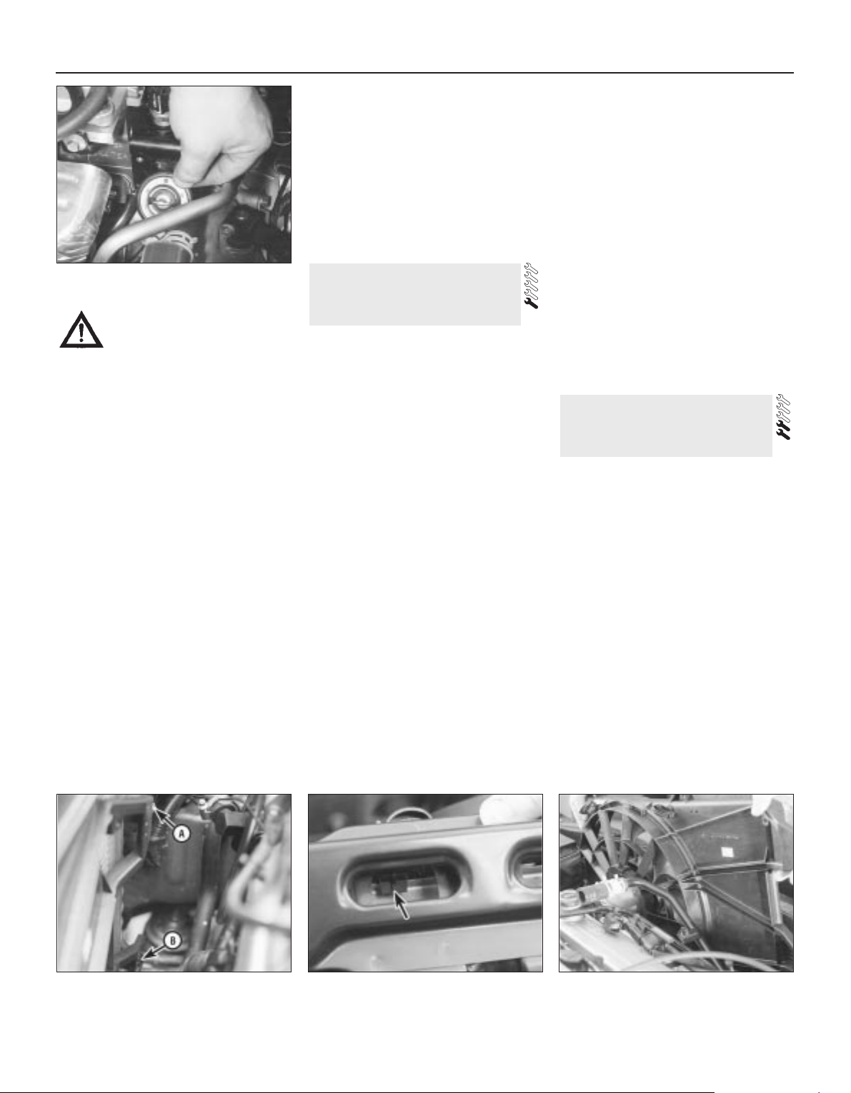
Caution: Don’t drive the vehicle
without a thermostat. The lack of
a thermostat will slow warm-up
time. The engine management system’s
ECU will then stay in warm-up mode for
longer than necessary, causing emissions
and fuel economy to suffer.
9 If the radiator top hose is hot, it means that
the coolant is flowing and the thermostat is
open. Consult the “Fault diagnosis” section at
the front of this manual to assist in tracing
possible cooling system faults.
Thermostat test
10 If the thermostat remains in the open
position at room temperature, it is faulty, and
must be renewed as a matter of course.
11 To test it fully, suspend the (closed)
thermostat on a length of string in a container
of cold water, with a thermometer beside it;
ensure that neither touches the side of the
container.
12 Heat the water, and check the
temperature at which the thermostat begins to
open; compare this value with that specified.
Continue to heat the water until the
thermostat is fully open; the temperature at
which this should happen is stamped in the
unit’s end. Remove the thermostat and allow
it to cool down; check that it closes fully.
13 If the thermostat does not open and close
as described, if it sticks in either position, or if
it does not open at the specified temperature,
it must be renewed.
Refitting
14 Refitting is the reverse of the removal
procedure. Clean the mating surfaces
carefully, renew the thermostat’s sealing ring
if it is worn or damaged, then refit the
thermostat with its air bleed valve uppermost
(see illustration). Tighten the water outlet
bolts to the specified torque wrench setting.
15 Refill the cooling system (see Chapter 1).
16 Start the engine and allow it to reach
normal operating temperature, then check for
leaks and proper thermostat operation.
Note: Refer to the warnings given in Section 1
of this Chapter before starting work.
Testing
1 The radiator cooling fan is controlled by the
engine management system’s ECU, acting on
the information received from the coolant
temperature sensor. Where twin fans or twospeed fans are fitted, control is through a
resistor assembly, secured to the bottom lefthand corner of the fan shroud - this can be
renewed separately if faulty.
2 First, check the relevant fuses and relays
(see Chapter 12).
3 To test the fan motor, unplug the electrical
connector, and use fused jumper wires to
connect the fan directly to the battery. If the
fan still does not work, renew the motor.
4 If the motor proved sound, the fault lies in
the coolant temperature sensor (see Section 6
for testing details), in the wiring loom (see
Chapter 12 for testing details) or in the engine
management system (see Chapter 6).
Removal and refitting
5 Disconnect the battery negative (earth) lead
(see Chapter 5, Section 1).
6 Unbolt the resonator support bracket from
the engine compartment front crossmember.
Slacken the two clamp screws securing the
resonator to the air mass meter and plenum
chamber hoses, then swing the resonator up
clear of the thermostat housing (see Chapter 4).
7 Drain the cooling system (see Chapter 1).
8 Remove the radiator top hose completely.
Disconnect the metal coolant pipe/hose from
the thermostat, and unbolt the coolant pipe
from the exhaust manifold heat shield.
9 Unplug the cooling fan electrical
connector(s), then release all wiring and hoses
from the fan shroud.
10 Unscrew the two nuts securing the fan
shroud, then lift the assembly to disengage it
from its bottom mountings and from the
radiator top edge (see illustrations).
11 Withdraw the fan and shroud as an
assembly (see illustration).
12 At the time of writing, the fan, motor and
shroud are available only as a complete
assembly, and must be renewed together if
faulty.
13 Refitting is the reverse of the removal
procedure. Ensure that the shroud is settled
correctly at all four mounting points before
refitting and tightening the nuts.
Note: Refer to the warnings given in Section 1
of this Chapter before starting work.
Coolant temperature gauge
sender
Testing
1 If the coolant temperature gauge is inopera-
tive, check the fuses first (see Chapter 12).
2 If the gauge indicates Hot at any time,
consult the “Fault finding” section at the end
of this manual, to assist in tracing possible
cooling system faults.
3 If the gauge indicates Hot shortly after the
engine is started from cold, unplug the
coolant temperature sender’s electrical
connector. If the gauge reading now drops,
renew the sender. If the reading remains high,
the wire to the gauge may be shorted to earth,
or the gauge is faulty.
4 If the gauge fails to indicate after the engine
has been warmed up (approximately
10 minutes) and the fuses are known to be
sound, switch off the engine. Unplug the
6 Cooling system electrical
switches and sensors -
testing, removal and refitting
5 Radiator electric cooling
fan(s) - testing,
removal and refitting
3•4 Cooling, heating and air conditioning systems
4.14 Ensure thermostat is refitted as
shown
5.10A Fan shroud is secured at top by
mounting nut (A), at bottom by clip (B) . . .
5.10B . . . and is hooked over radiator top
edge (one point arrowed)
5.11 Removing radiator electric cooling
fan and shroud assembly
Page 93
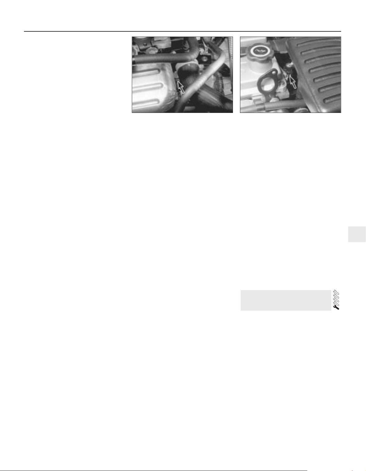
sender’s electrical connector, and use a
jumper wire to connect the white/red wire to a
clean earth point (bare metal) on the engine.
Switch on the ignition without starting the
engine. If the gauge now indicates Hot, renew
the sender.
5 If the gauge still does not work, the circuit
may be open, or the gauge may be faulty. See
Chapter 12 for additional information.
Removal
6 Unbolt the resonator support bracket from
the engine compartment front crossmember.
Slacken the two clamp screws securing the
resonator to the air mass meter and plenum
chamber hoses, then swing the resonator up
clear of the thermostat housing (see Chapter 4).
7 Drain the cooling system (see Chapter 1).
8 Disconnect the expansion tank coolant
hose and the radiator top hose from the
thermostat housing’s water outlet, then
disconnect the metal coolant pipe/hose from
the thermostat.
9 Unplug the electrical connector from the
sender (see illustration).
10 Unscrew the sender and withdraw it.
Refitting
11 Clean as thoroughly as possible the
opening in the thermostat housing, then apply
a light coat of sealant to the sender’s threads.
Screw in the sender and tighten it to the
specified torque wrench setting, and plug in
its electrical connector.
12 Reconnect the hoses and refit the
resonator, top-up the cooling system (see
Chapter 1) and run the engine. Check for
leaks and proper gauge operation.
Coolant temperature sensor
Testing
13 Disconnect the battery negative (earth)
lead (see Chapter 5, Section 1).
14 Unbolt the resonator support bracket
from the engine compartment front
crossmember. Slacken the two clamp screws
securing the resonator to the air mass meter
and plenum chamber hoses, then swing the
resonator up clear of the thermostat housing
(see Chapter 4).
15 Unplug the electrical connector from the
sensor (see illustration).
16 Using an ohmmeter, measure the
resistance between the sensor terminals.
Depending on the temperature of the sensor
tip, the resistance measured will vary, but
should be within the broad limits given in the
Specifications Section of this Chapter. If the
sensor’s temperature is varied - by removing
it (see below) and placing it in a freezer for a
while, or by warming it gently - its resistance
should alter accordingly.
17 If the results obtained show the sensor to
be faulty, renew it.
18 On completion, plug in the connector and
refit the resonator.
Removal
19 Disconnect the battery negative (earth)
lead (see Chapter 5, Section 1).
20 Unbolt the resonator support bracket
from the engine compartment front
crossmember. Slacken the two clamp screws
securing the resonator to the air mass meter
and plenum chamber hoses, then swing the
resonator up clear of the thermostat housing
(see Chapter 4).
21 With the engine completely cool, remove
the expansion tank filler cap to release any
pressure, then refit the cap. Provided you
work swiftly and plug the opening as soon as
the sensor is unscrewed, coolant loss will thus
be minimised; this will avoid the draining of
the complete cooling system which would
otherwise be necessary (see Chapter 1).
22 Unplug the electrical connector from the
sensor.
23 Unscrew the sensor and withdraw it. If the
cooling system has not been drained, plug the
opening as quickly as possible.
Refitting
24 Clean as thoroughly as possible the
opening in the thermostat housing, then apply
a light coat of sealant to the sensor’s threads.
Remove the material used to plug the sensor
hole (where applicable), and quickly install the
sensor to prevent coolant loss. Tighten the
sensor to the specified torque wrench setting,
and plug in its electrical connector.
25 Refit the resonator, top-up the cooling
system (see Chapter 1) and run the engine,
checking for leaks.
Coolant low level switch
Testing
26 The switch is a reed-type unit mounted in
the bottom of the cooling system expansion
tank, activated by a magnetic float. If the
coolant level falls to the “MIN” level or less,
the appropriate bulb lights in the warning
display.
27 If the bulb fails to light during the 5second bulb test, check the bulb, and renew if
necessary as described in Chapter 12.
28 To check the switch itself, unplug its
electrical connector, and use an ohmmeter to
measure the resistance across the switch
terminals. With the float up, a resistance of
90 ohms should be measured; when it is
down, the resistance should increase to
approximately 150 kilohms.
29 If the results obtained from the check are
significantly different from those expected,
the switch is faulty, and must be renewed.
30 If the switch and bulb are proven to be
sound, the fault must be in the wiring or in the
auxiliary warning control assembly (see
Chapter 12).
Removal
31 Disconnect the battery negative (earth)
lead (see Chapter 5, Section 1).
32 Remove the expansion tank (see Section 7).
33 Unplug the switch electrical connector.
34 Release the switch by twisting its retainer
anti-clockwise, then withdraw it.
Refitting
35 Refitting is the reverse of the removal
procedure. Refill the cooling system (see
Chapter 1). Start the engine, and check for
coolant leaks when it is fully warmed-up.
Note: Refer to the warnings given in Section 1
of this Chapter before starting work.
Radiator
Removal
Note: If leakage is the reason for removing the
radiator, bear in mind that minor leaks can
often be cured using a radiator sealant with
the radiator in situ.
1 Remove the radiator fan and shroud
assembly (see Section 5).
2 Disconnect the bottom hose from the
radiator.
3 If the vehicle has automatic transmission,
disconnect the fluid cooler lines, and plug the
lines and fittings.
4 If the vehicle has air conditioning, unscrew
the condenser mounting nuts or bolts, detach
the condenser from the radiator, and tie it to
the engine compartment front crossmember.
7 Radiator and expansion tank -
removal, inspection and refitting
Cooling, heating and air conditioning systems 3•5
3
6.9 Location (arrowed) of coolant
temperature gauge sender
6.15 Location (arrowed) of coolant
temperature sensor
Page 94
Warning: Do not disconnect any
of the refrigerant hoses.
5 Unbolt the radiator mounting brackets from
the subframe; note that they are handed, and
are marked to ensure correct refitting (see
illustration). Collect the bottom mounting
rubbers, noting which way up they are fitted,
and store them carefully.
6 Carefully lower the radiator from the
vehicle, and withdraw it.
7 With the radiator removed, it can be
inspected for leaks and damage. If it needs
repair, have a radiator specialist or dealer
service department perform the work, as
special techniques are required.
8 Insects and dirt can be removed from the
radiator with a garden hose or a soft brush.
Don’t bend the cooling fins as this is done.
Refitting
9 Refitting is the reverse of the removal
procedure. Be sure the mounting rubbers are
seated properly at the base of the radiator.
10 After refitting, refill the cooling system
with the proper mixture of antifreeze and
water (see Chapter 1).
11 Start the engine, and check for leaks.
Allow the engine to reach normal operating
temperature, indicated by the radiator top
hose becoming hot. Recheck the coolant
level, and add more if required.
12 If working on an vehicle with automatic
transmission, check and add transmission
fluid as needed (see Chapter 1).
Expansion tank
13 With the engine completely cool, remove
the expansion tank filler cap to release any
pressure, then refit the cap.
14 Disconnect the hoses from the tank,
upper hose first. As each hose is
disconnected, drain the tank’s contents into a
clean container. If the antifreeze is not due for
renewal, the drained coolant may be re-used,
if it is kept clean.
15 Unscrew the tank’s two mounting bolts
and withdraw it, unplugging the coolant low
level switch electrical connector (where fitted).
16 Wash out the tank, and inspect it for
cracks and chafing - renew it if damaged.
17 Refitting is the reverse of the removal
procedure. Refill the cooling system with the
proper mixture of antifreeze and water (see
Chapter 1), then start the engine and allow it
to reach normal operating temperature,
indicated by the radiator top hose becoming
hot. Recheck the coolant level and add more
if required, then check for leaks.
Note: Refer to the warnings given in Section 1
of this Chapter before starting work.
Check
1 A failure in the water pump can cause
serious engine damage due to overheating.
2 There are three ways to check the operation
of the water pump while it’s installed on the
engine. If the pump is defective, it should be
replaced with a new or rebuilt unit.
3 With the engine running at normal operating
temperature, squeeze the radiator top hose. If
the water pump is working properly, a
pressure surge should be felt as the hose is
released.
Warning: Keep your hands away
from the radiator electric
cooling fan blades!
4 Remove the timing belt covers (see Chapter 2, Part A). Water pumps are equipped with
weep or vent holes. If a failure occurs in the
pump seal, coolant will leak from the hole. In
most cases you’ll need an electric torch to
find the hole on the water pump from
underneath to check for leaks.
5 If the water pump shaft bearings fail, there
may be a howling sound at the drivebelt end
of the engine while it’s running. Shaft wear
can be felt if the water pump pulley is rocked
up and down. Don’t mistake drivebelt
slippage, which causes a squealing sound, for
water pump bearing failure.
Removal and refitting
6 Remove the timing belt and tensioner (see
Chapter 2, Part A). As noted in Chapter 2, if
the belt is fouled with coolant, it must be
renewed as a matter of course.
7 Drain the cooling system (see Chapter 1).
8 Disconnect the radiator bottom hose from
the pump union. It is easier to reach this union
if the power steering pump is unbolted and
moved aside as described in Chapter 10 (see
illustration). There is no need to disconnect
any of the power steering system hoses.
9 Unbolt and remove the water pump (see
illustration). If the pump is to be renewed,
unbolt the timing belt guide pulleys, and
transfer them to the new pump.
10 Clean the mating surfaces carefully; the
gasket must be renewed whenever it is
disturbed (see illustration).
11 On refitting, use grease to stick the new
gasket in place, refit the pump, and tighten
the pump bolts to the specified torque wrench
setting.
12 The remainder of the reassembly
procedure is the reverse of dismantling. Note
that a new tensioner spring and retaining pin
must be fitted if the timing belt has been
removed for the first time. Tighten all
fasteners to the specified torque wrench
settings, and refill the system with coolant as
described in Chapter 1.
8 Water pump -
check, removal and refitting
3•6 Cooling, heating and air conditioning systems
7.5 Radiator mounting bracket-to-
subframe bolts (A), air conditioning system
condenser mounting bolt (B)
8.8 Power steering system pump should
be removed to reach water pump hose
union (arrowed)
8.9 Unscrew bolts (arrowed) . . . 8.10 . . . to remove water pump - always
renew gasket and clean all mating
surfaces carefully
Page 95
Heater blower motor
Removal
1 Disconnect the battery negative (earth) lead
(see Chapter 5, Section 1).
2 Release the four clips (by pulling them out)
securing the passenger side footwell upper
trim panel, then withdraw the panel.
3 Unplug the motor’s electrical connector.
4 Lift the motor’s retaining lug slightly, twist
the motor anti-clockwise (seen from beneath)
through approximately 30°, then withdraw the
assembly.
5 The motor’s control resistor can be
removed by sliding a slim screwdriver into the
slot provided in one end. Press the
screwdriver in approximately 5 mm against
spring pressure, and prise the resistor out
(see illustration).
Refitting
6 Refitting is the reverse of the removal
procedure. Refit the motor, and twist it
clockwise until the retaining lug engages
securely (see illustration).
Heater matrix
Removal
7 Disconnect the battery negative (earth) lead
(see Chapter 5, Section 1).
8 Drain the cooling system (see Chapter 1).
9 Disconnect the coolant hoses from the
heater matrix unions protruding through the
engine compartment bulkhead (see
illustrations).
10 Working inside the passenger
compartment, remove the trim panels from
each footwell, just in front of the centre
console. Each panel is secured by two
screws. If additional clearance is required, the
centre console can be removed as well (see
Chapter 11), but this is not essential.
11 Remove the single screw to release the air
duct in the base of the heater unit (see
illustration).
12 Remove the three Torx-type screws (size
T20) securing the air distributor to the heater
unit bottom cover, then release the clips.
There is a single plastic clip on each side, and
additional metal clips may be found. Push the
duct up to retract it, and withdraw the air
distributor (see illustration).
13 Release the clips - there are two plastic
clips on each side, and additional metal clips
may be found - then withdraw the heater
unit’s bottom cover, complete with the matrix
(see illustration).
14 Undo the screw and withdraw the clamp
to separate the matrix from the bottom cover
(see illustration).
Refitting
15 Refitting is the reverse of the removal
procedure. Additional metal clips may be
required to secure the heater unit’s bottom
cover and the air distributor. Ensure that the
9 Heater/ventilation components
- removal and refitting
Cooling, heating and air conditioning systems 3•7
3
9.12 . . . release clips (A) to free air
distributor from base of heater unit - note
clips (B) securing . . .
9.13 . . . heater unit’s bottom cover,
complete with matrix
9.14 Remove clamp (one screw) to separate
matrix from heater unit’s bottom cover
9.5 Heater blower motor control resistor
can be prised out of heater unit
9.6 Ensure blower motor retaining lug
(arrowed) engages securely in heater unit
on reassembly
9.9A Coolant pipes to heater matrix must
be disconnected . . .
9.9B . . . but can be reached best from
beneath vehicle (arrowed)
9.11 Remove screw to allow air duct to be
retracted into air distributor at base of
heater unit . . .
Page 96
duct is lowered from the air distributor and
secured with its screw.
16 Refill the cooling system with the proper
mixture of antifreeze and water (see Chapter
1). Start the engine and allow it to reach
normal operating temperature, indicated by
the radiator top hose becoming hot. Recheck
the coolant level and add more if required,
then check for leaks. Check the operation of
the heater.
Pollen filter
17 Refer to Chapter 1.
Blower/air conditioning control
Removal
1 Disconnect the battery negative (earth) lead
(see Chapter 5, Section 1).
2 Remove the ashtray. Referring to the
relevant Sections of Chapter 11, undo the two
upper screws from the centre console and
pull out the cassette storage compartment,
then remove the radio/cassette player.
3 Pull the heater control/radio bezel out of the
three clips securing its top edge, pull it
forwards and unplug the switch electrical
connector (where fitted).
4 Pull off the heater control knobs, and
remove the screw securing each end of the
heater control unit (see illustration). Pull the
control unit out of the facia.
5 Unplug the two electrical connectors from
the blower/air conditioning control. Remove
the retaining screw and withdraw the control,
twisting it to release it from the panel.
Refitting
6 Refitting is the reverse of the removal
procedure. Check the operation of the control
on completion.
Temperature control
Removal
7 Remove the heater control unit as
described in paragraphs 1 to 4 above.
8 On vehicles without air conditioning,
unhook the operating cable from the
temperature control (see illustration); where
air conditioning is fitted, unplug the control’s
electrical connector. Undo the retaining
screw, and withdraw the control.
Refitting
9 Refitting is the reverse of the removal
procedure; check the operation of the control
on completion.
Air distribution control
Removal
10 Remove the heater control unit as
described in paragraphs 1 to 4 above. Unplug
the electrical connectors, and unhook the
operating cable (where fitted) to withdraw the
unit (see illustration).
11 Use a pair of slim screwdrivers to release
the clips on each side of the control, then
withdraw the control from the unit.
Refitting
12 Refitting is the reverse of the removal
procedure. Check the operation of the
controls on completion.
General information
The air conditioning system consists of a
condenser mounted in front of the radiator, an
evaporator mounted adjacent to the heater
matrix, a compressor mounted on the engine,
an accumulator/dehydrator, and the plumbing
connecting all of the above components - this
contains a choke (or “venturi”) mounted in the
inlet to the evaporator, which creates the drop
in pressure required to produce the cooling
effect (see illustration).
A blower fan forces the warmer air of the
passenger compartment through the
evaporator core (rather like a radiator in
reverse), transferring the heat from the air to
11 Air conditioning system -
general information and
precautions
10 Heater/air conditioning
controls - removal and refitting
3•8 Cooling, heating and air conditioning systems
10.4 Remove screws (arrowed) securing
each end of heater control unit
10.8 Unhooking operating cable from
temperature control - note retaining screw
(arrowed)
10.10 Unplugging electrical connectors
from rear of heater control unit
11.1 Air conditioning system components
1 Quick-release Schrader valve-type
coupling - high-pressure side
2 Quick-release Schrader valve-type
coupling - low-pressure side
3 Pressure-cycling switch - low-pressure side
4 Accumulator/dehydrator
5 Compressor
6 Condenser
7 Pressure-regulating switch - high-pressure
side
Page 97
the refrigerant. The liquid refrigerant boils off
into low-pressure vapour, taking the heat with
it when it leaves the evaporator.
Precautions
Warning: The air conditioning
system is under high pressure.
Do not loosen any fittings or
remove any components until
after the system has been discharged. Air
conditioning refrigerant should be properly
discharged into an approved type of
container, at a dealer service department
or an automotive air conditioning repair
facility capable of handling R134a
refrigerant. Always wear eye protection
when disconnecting air conditioning
system fittings.
When an air conditioning system is fitted, it
is necessary to observe the following special
precautions whenever dealing with any part of
the system, its associated components, and
any items which necessitate disconnection of
the system:
(a) While the refrigerant used - R134a - is
less damaging to the environment than
the previously-used R12, it is still a very
dangerous substance. It must not be
allowed into contact with the skin or eyes,
or there is a risk of frostbite. It must also
not be discharged in an enclosed space while it is not toxic, there is a risk of
suffocation. The refrigerant is heavier than
air, and so must never be discharged over
a pit.
(b) The refrigerant must not be allowed to
come in contact with a naked flame,
otherwise a poisonous gas will be created
- under certain circumstances, this can
form an explosive mixture with air. For
similar reasons, smoking in the presence
of refrigerant is highly dangerous,
particularly if the vapour is inhaled
through a lighted cigarette.
(c) Never discharge the system to the
atmosphere - R134a is not an ozonedepleting ChloroFluoroCarbon (CFC) as is
R12, but is instead a hydrofluorocarbon,
which causes environmental damage by
contributing to the “greenhouse effect” if
released into the atmosphere.
(d) R134a refrigerant must not be mixed with
R12; the system uses different seals (now
green-coloured, previously black) and has
different fittings requiring different tools,
so that there is no chance of the two
types of refrigerant becoming mixed
accidentally.
(e) If for any reason the system must be
disconnected, entrust this task to your
Ford dealer or a refrigeration engineer.
(f) It is essential that the system be
professionally discharged prior to using
any form of heat - welding, soldering,
brazing, etc - in the vicinity of the system,
before having the vehicle oven-dried at a
temperature exceeding 70°C after
repainting, and before disconnecting any
part of the system.
Warning: The air conditioning
system is under high pressure.
Do not loosen any fittings or
remove any components until after the
system has been discharged. Air
conditioning refrigerant should be properly
discharged into an approved type of
container, at a dealer service department
or an automotive air conditioning repair
facility capable of handling R134a
refrigerant. Cap or plug the pipe lines as
soon as they are disconnected, to prevent
the entry of moisture. Always wear eye
protection when disconnecting air
conditioning system fittings.
Note: This Section refers to the components
of the air conditioning system itself - refer to
Sections 9 and 10 for details of components
common to the heating/ventilation system.
Condenser
1 Have the refrigerant discharged at a dealer
service department or an automotive air
conditioning repair facility.
2 Disconnect the battery negative (earth) lead
(see Chapter 5, Section 1).
3 Remove the radiator undershield (see
Chapter 1).
4 Using the Ford service tool 34-001,
disconnect the refrigerant lines from the
condenser. Immediately cap the open fittings,
to prevent the entry of dirt and moisture.
5 Unbolt the condenser (see illustration 7.5)
and lift it out of the vehicle. Store it upright, to
prevent oil loss.
6 Refitting is the reverse of removal.
7 If a new condenser was installed, add 20 cc
of refrigerant oil to the system.
8 Have the system evacuated, charged and
leak-tested by the specialist who discharged
it.
Evaporator
9 The evaporator is mounted with the heater
matrix. Apart from the need to have the
refrigerant discharged, and to use Ford
service tools 34-001 and 34-003 to
disconnect the lines, the procedure is as
described in Section 9 of this Chapter.
10 On reassembly, if a new evaporator was
installed, add 20 cc of refrigerant oil to the
system.
11 Have the system evacuated, charged and
leak-tested by the specialist who discharged
it.
Compressor
12 Have the refrigerant discharged at a
dealer service department or an automotive
air conditioning repair facility.
13 Disconnect the battery negative (earth)
lead (see Chapter 5, Section 1).
14 Remove the radiator undershield (see
Chapter 1).
15 Remove the auxiliary drivebelt (see
Chapter 1).
16 Unbolt the compressor from the cylinder
block/crankcase, press it to one side, and
unscrew the clamping bolt to disconnect the
refrigerant lines. Plug the line connections,
swing the compressor upright, unplug its
electrical connector, then withdraw the
compressor from the vehicle. Note: Keep the
compressor level during handling and storage.
If the compressor has seized, or if you find
metal particles in the refrigerant lines, the
system must be flushed out by an air
conditioning technician, and the
accumulator/dehydrator must be renewed.
17 Prior to installation, turn the compressor
clutch centre six times, to disperse any oil that
has collected in the head.
18 Refit the compressor in the reverse order
of removal; renew all seals disturbed.
19 If you are installing a new compressor,
refer to the compressor manufacturer’s
instructions for adding refrigerant oil to the
system.
20 Have the system evacuated, charged and
leak-tested by the specialist that discharged
it.
Accumulator/dehydrator
21 Have the refrigerant discharged at a
dealer service department or an automotive
air conditioning repair facility.
22 Disconnect the battery negative (earth)
lead (see Chapter 5, Section 1).
23 The accumulator/dehydrator, which acts
as a reservoir and filter for the refrigerant, is
located in the left-hand front corner of the
engine compartment. Using the Ford service
tool 34-003, disconnect the refrigerant line
next to the accumulator/dehydrator from the
compressor. Immediately cap the open
fittings, to prevent the entry of dirt and
moisture, then unplug the pressure-cycling
switch electrical connector (see illustration).
24 Remove the radiator undershield (see
Chapter 1).
25 Unbolt the accumulator/dehydrator from
the front suspension subframe.
26 Using the Ford service tool 34-003,
disconnect the lower refrigerant line from the
accumulator/dehydrator. It may be necessary
12 Air conditioning system
components -
removal and refitting
Cooling, heating and air conditioning systems 3•9
3
12.23 Unplug pressure-cycling switch
electrical connector (arrowed)
Page 98
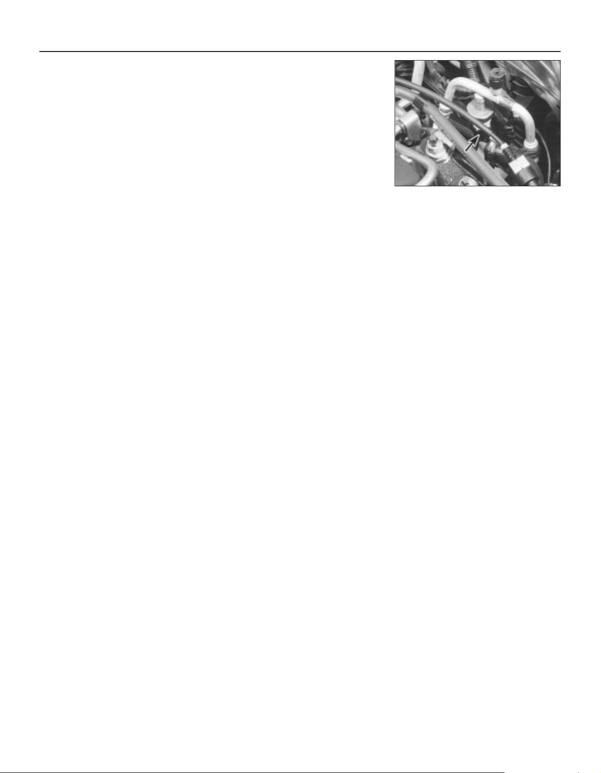
to unscrew the pressure-cycling switch to
allow the use of the tool. Immediately cap the
open fittings, to prevent the entry of dirt and
moisture.
27 Withdraw the accumulator/dehydrator.
28 Refit the accumulator/dehydrator in the
reverse order of removal; renew all seals
disturbed.
29 If you are installing a new accumulator/
dehydrator, refer to the manufacturer’s
instructions for adding refrigerant oil to the
system.
30 Have the system evacuated, charged and
leak-tested by the specialist that discharged
it.
Pressure-cycling and pressureregulating switches
31 Have the refrigerant discharged at a
dealer service department or an automotive
air conditioning repair facility.
32 Disconnect the battery negative (earth)
lead (see Chapter 5, Section 1).
33 Unplug the switch electrical connector,
and unscrew it (see illustration).
34 Refitting is the reverse of the removal
procedure; there is no need to top-up the
refrigerant oil.
35 Have the system evacuated, charged and
leak-tested by the specialist that discharged
it.
3•10 Cooling, heating and air conditioning systems
12.33 Unplug pressure-regulating switch
electrical connector (arrowed)
Page 99
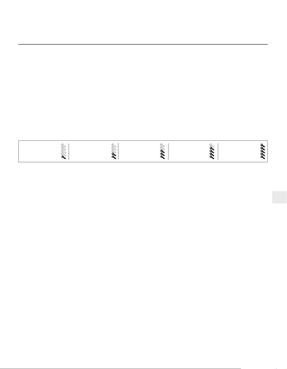
Chapter 4 Fuel and exhaust systems
Accelerator cable (models with traction control) -
removal, refitting and adjustment . . . . . . . . . . . . . . . . . . . . . . . . . 6
Accelerator cable (models without traction control) -
removal, refitting and adjustment . . . . . . . . . . . . . . . . . . . . . . . . . 5
Accelerator pedal - removal and refitting . . . . . . . . . . . . . . . . . . . . . 7
Air cleaner assembly/air intake components - removal and refitting . 4
Air filter element renewal . . . . . . . . . . . . . . . . . . . . . . . See Chapter 1
Catalytic converter . . . . . . . . . . . . . . . . . . . . . . . . . . . . See Chapter 6
Exhaust manifold - removal and refitting . . . . . . . . . . . See Chapter 2A
Exhaust system - general information and component renewal . . . . 17
Exhaust system check . . . . . . . . . . . . . . . . . . . . . . . . . See Chapter 1
Fuel cut-off switch - removal and refitting . . . . . . . . . . . . . . . . . . . . 13
Fuel filter renewal . . . . . . . . . . . . . . . . . . . . . . . . . . . . . See Chapter 1
Fuel injection system/engine management system - check . . . . . . . 15
Fuel injection system/engine management system - general . . . . . 14
Fuel lines and fittings - general information . . . . . . . . . . . . . . . . . . . 3
Fuel pump/fuel gauge sender unit - removal and refitting . . . . . . . . 9
Fuel pump/fuel pressure - check . . . . . . . . . . . . . . . . . . . . . . . . . . . 8
Fuel system - depressurisation . . . . . . . . . . . . . . . . . . . . . . . . . . . . . 2
Fuel system components - check and renewal . . . . . . . . . . . . . . . . 16
Fuel tank - removal and refitting . . . . . . . . . . . . . . . . . . . . . . . . . . . . 10
Fuel tank cleaning and repair - general information . . . . . . . . . . . . . 11
General information and precautions . . . . . . . . . . . . . . . . . . . . . . . . 1
Idle speed and mixture check and adjustment . . . . . . See Section 14
Inlet manifold - removal and refitting . . . . . . . . . . . . . . See Chapter 2A
Oxygen sensor . . . . . . . . . . . . . . . . . . . . . . . . . . . . . . . See Chapter 6
Roll-over valves - removal and refitting . . . . . . . . . . . . . . . . . . . . . . . 12
Underbody fuel/brake line check . . . . . . . . . . . . . . . . . See Chapter 1
Underbonnet hose check . . . . . . . . . . . . . . . . . . . . . . . See Chapter 1
General
Idle speed:
Regulated - nominal (± 50 rpm) . . . . . . . . . . . . . . . . . . . . . . . . . . . . . . 830 to 880 rpm*
Unregulated - base . . . . . . . . . . . . . . . . . . . . . . . . . . . . . . . . . . . . . . . 1500 rpm*
Idle mixture (CO level) . . . . . . . . . . . . . . . . . . . . . . . . . . . . . . . . . . . . . . . Not available
* Given for reference only - not adjustable.
Rev limiter operation
Fuel injectors shut off at:
Automatic transmission, position “N” selected . . . . . . . . . . . . . . . . . . 4100 rpm
Automatic transmission, any other position selected . . . . . . . . . . . . . 6800 rpm (approximately)
Manual transmission . . . . . . . . . . . . . . . . . . . . . . . . . . . . . . . . . . . . . . 6800 to 7100 rpm
Fuel pressure
Regulated fuel pressure - engine running at idle speed:
Pressure regulator vacuum hose connected . . . . . . . . . . . . . . . . . . . 2.1 ± 0.2 bars
Pressure regulator vacuum hose disconnected . . . . . . . . . . . . . . . . . 2.7 ± 0.2 bars
Note: When the ignition is switched off, the system should hold 1.8 bars for 5 minutes. If the engine is hot, the pressure may rise to maximum of
2.7 bars during this check. Pressure regulator (when reconnected) should prevent any higher pressure being reached.
Fuel injectors
Resistance . . . . . . . . . . . . . . . . . . . . . . . . . . . . . . . . . . . . . . . . . . . . . . . . 13.7 to 15.2 ohms
Idle speed control valve
Resistance . . . . . . . . . . . . . . . . . . . . . . . . . . . . . . . . . . . . . . . . . . . . . . . . 6 to 14 ohms
Idle-increase solenoid valve
Resistance . . . . . . . . . . . . . . . . . . . . . . . . . . . . . . . . . . . . . . . . . . . . . . . . 50 to 120 ohms
Torque wrench settings Nm lbf ft
Plenum chamber-to-inlet manifold fasteners . . . . . . . . . . . . . . . . . . . . . 4 3
Throttle housing-to-inlet manifold screws . . . . . . . . . . . . . . . . . . . . . . . 10 7
Idle speed control valve bolts . . . . . . . . . . . . . . . . . . . . . . . . . . . . . . . . . 6 4
Fuel pressure regulator bolts . . . . . . . . . . . . . . . . . . . . . . . . . . . . . . . . . 6 4
Fuel injector bolts . . . . . . . . . . . . . . . . . . . . . . . . . . . . . . . . . . . . . . . . . . 6 4
Fuel rail-to-inlet manifold bolts . . . . . . . . . . . . . . . . . . . . . . . . . . . . . . . . 10 7
Fuel feed and return line threaded couplings at fuel rail . . . . . . . . . . . . . 24 to 30 17 to 22
All exhaust system nuts and bolts . . . . . . . . . . . . . . . . . . . . . . . . . . . . . 40 to 45 30 to 33
4•1
Easy, suitable for
novice with little
experience
Fairly easy, suitable
for beginner with
some experience
Fairly difficult, suitable
for competent DIY
mechanic
Difficult, suitable for
experienced DIY
mechanic
Very difficult,
suitable for expert DIY
or professional
Degrees of difficulty
Specifications
Contents
4
Page 100
This Chapter is concerned with those
features of the engine management system
that supply clean fuel and air to the engine,
meter it in the required proportions, and
dispose of the results. Since the emission
control sub-systems modify the functions of
both the fuel and exhaust sub-systems, all of
which are integral parts of the whole engine
management system, there are many crossreferences to Chapters 5 and 6. Information
on the electronic control system, its fault
diagnosis, sensors and actuators, is given in
Chapter 6.
The air intake system consists of several
plastics components designed to eliminate
induction roar as much as possible. The air
intake tube (opening behind the direction
indicator/headlight assembly) is connected,
via small and large resonators located under
the front left-hand wing, to the air cleaner
assembly in the engine compartment. Once it
has passed through the filter element and the
air mass meter, the air enters the plenum
chamber mounted above the throttle housing
and inlet manifold; the resonator mounted in
the engine compartment further reduces noise
levels.
The fuel system consists of a plastic tank
(mounted under the body, beneath the rear
seats), combined metal and plastic fuel hoses,
an electric fuel pump mounted in the fuel tank,
and an electronic fuel injection system.
The exhaust system consists of an exhaust
manifold, the front downpipe and catalytic
converter and, on production-fit systems, a
rear section incorporating two or three
silencers and the tailpipe assembly. The
service replacement exhaust system consists
of three or four sections: the front
downpipe/catalytic converter, the
intermediate pipe and front silencer, and the
tailpipe and rear silencer. On some versions,
the tailpipe is in two pieces, with two rear
silencers. The system is suspended
throughout its entire length by rubber
mountings.
Extreme caution should be exercised when
dealing with either the fuel or exhaust
systems. Fuel is a primary element for
combustion. Be very careful! The exhaust
system is an area for exercising caution, as it
operates at very high temperatures. Serious
burns can result from even momentary
contact with any part of the exhaust system,
and the fire risk is ever-present. The catalytic
converter in particular runs at very high
temperatures - refer to the information in
Chapter 6.
Warning: Many of the procedures
in this Chapter require the
removal of fuel lines and
connections, which may result in
some fuel spillage. Petrol is extremely
flammable, so take extra precautions
when you work on any part of the fuel
system. Don’t smoke, or allow open flames
or bare light bulbs, near the work area.
Don’t work in a garage where a natural
gas-type appliance (such as a water
heater or clothes dryer) with a pilot light is
present. If you spill any fuel on your skin,
rinse it off immediately with soap and
water. When you perform any kind of work
on the fuel system, wear safety glasses,
and have a Class B type fire extinguisher
on hand. Before carrying out any operation
on the fuel system, refer also to the
precautions given in “Safety first!” at the
beginning of this manual, and follow them
implicitly. Petrol is a highly-dangerous and
volatile liquid, and the precautions
necessary when handling it cannot be
overstressed.
Warning: The fuel system will
remain pressurised for long
periods of time after the engine is
switched off - this pressure must
be released before any part of the system
is disturbed. Petrol is extremely
flammable, so take extra precautions
when you work on any part of the fuel
system. Don’t smoke, or allow open flames
or bare light bulbs, near the work area.
Don’t work in a garage where a natural
gas-type appliance (such as a water
heater or clothes dryer) with a pilot light is
present. If you spill any fuel on your skin,
rinse it off immediately with soap and
water. When you perform any kind of work
on the fuel system, wear safety glasses,
and have a Class B type fire extinguisher
on hand.
1 The fuel system referred to in this Chapter
is defined as the fuel tank and tank-mounted
fuel pump/fuel gauge sender unit, the fuel
filter, the fuel injectors and the pressure
regulator in the injector rail, and the metal
pipes and flexible hoses of the fuel lines
between these components. All these contain
fuel, which will be under pressure while the
engine is running and/or while the ignition is
switched on.
2 The pressure will remain for some time after
the ignition has been switched off, and must
be relieved before any of these components is
disturbed for servicing work.
3 The simplest method is simply to
disconnect the fuel pump’s electrical supply
while the engine is running - either by
removing the fuel pump fuse (number 14), or
by lifting the red button on the fuel cut-off
switch (see Section 13) - and to allow the
engine to idle until it dies through lack of fuel
pressure. Turn the engine over once or twice
on the starter to ensure that all pressure is
released, then switch off the ignition; do not
forget to refit the fuse (or depress the red
button, as appropriate) when work is
complete.
4 The Ford method of depressurisation is to
use service tool 29-033 fitted to the fuel rail
pressure test/release fitting - a Schrader-type
valve with a blue plastic cap, located on the
union of the fuel feed line and the fuel rail - to
release the pressure, using a suitable
container and wads of rag to catch the spilt
fuel. Do not simply depress the valve core to
release fuel pressure - droplets of fuel will
spray out, with a consequent risk of fire, and
of personal injury through fuel getting into
your eyes.
Warning: Either procedure will
merely relieve the increased
pressure necessary for the
engine to run. Remember that
fuel will still be present in the system
components, and take precautions
accordingly before disconnecting any of
them.
5 Note that, once the fuel system has been
depressurised and drained (even partially), it
will take significantly longer to restart the
engine - perhaps several seconds of cranking
- before the system is refilled and pressure
restored.
Warning: The fuel system
pressure must be released before
any part of the system is
disturbed - see Section 2. Petrol
is extremely flammable, so take extra
precautions when you work on any part of
the fuel system. Don’t smoke, or allow
open flames or bare light bulbs, near the
work area. Don’t work in a garage where a
natural gas-type appliance (such as a
water heater or clothes dryer) with a pilot
light is present. If you spill any fuel on your
skin, rinse it off immediately with soap and
water. When you perform any kind of work
on the fuel system, wear safety glasses,
and have a Class B type fire extinguisher
on hand.
Disconnecting and connecting
quick-release couplings
1 Quick-release couplings are employed at all
unions in the fuel feed and return lines.
2 Before disconnecting any fuel system
component, relieve the residual pressure in
the system (see Section 2), and equalise tank
pressure by removing the fuel filler cap.
Warning: This procedure will
merely relieve the increased
pressure necessary for the
engine to run - remember that
fuel will still be present in the system
components, and take precautions
accordingly before disconnecting any of
them.
3 Fuel lines and fittings -
general information
2 Fuel system - depressurisation
1 General information and
precautions
4•2 Fuel and exhaust systems
 Loading...