

Page 1
Page 2
Page 3

Table of Contents
Introduction ....................................................1
Instrumentation .............................................. 7
Electronic Sound Systems ......................... 45
Controls and Features ................................ 71
Seating and Safety Restraints ................ 123
Starting ......................................................... 155
Driving ......................................................... 161
Roadside Emergencies .............................. 179
Maintenance and Care ............................. 209
Capacities and Specifications ................. 257
Reporting Safety Defects
(U.S. Only) .................................................. 263
Customer Assistance ................................. 265
Accessories .................................................. 277
Quick Index ................................................ 285
Index ............................................................. 295
Service Station Information .................... 316
Page 4

Introduction
At Ford Motor Company, excellence is the
continuous commitment to achieve the best
result possible. It is dedication to learning what
you want, determination to develop the right
concept, and execution of that concept with care,
precision, and attention to detail. In short,
excellence means being the standard by which
others are judged.
Our Guiding Principles
Quality comes first. For your satisfaction, the
❑
quality of our products and services must be
our number one priority.
You are the focus of everything we do. Our
❑
work must be done with you in mind,
providing better products and services than
our competition.
Continuous improvement is essential to our
❑
success. We must strive for excellence in
everything we do: in our products — in their
safety and value — and in our services, our
human relations, our competitiveness, and
our profitability.
Employee involvement is our way of life.
❑
We are a team. We must treat one another
with trust and respect.
Dealers and suppliers are our partners. We
❑
must maintain mutually beneficial
relationships with dealers, suppliers, and our
other business associates.
1
Page 5

Integrity is never compromised. Our conduct
❑
worldwide must be pursued in a manner that
is socially responsible and commands respect
for its integrity and for its positive
contributions to society.
This Guide
Congratulations on the purchase of your new
vehicle. This guide has information about the
equipment and the options for your new vehicle.
You may not have bought all of the options
available to you. If you do not know which
information applies to your vehicle, talk to your
dealer.
This guide describes equipment and gives
specifications for equipment that was in effect
when this guide was approved for printing. Ford
may discontinue models or change specifications
or design without any notice and without
incurring obligation.
NOTES and WARNINGS
NOTES give you additional information about
the subject matter you are referencing.
WARNINGS remind you to be especially careful
in those areas where carelessness can cause
damage to your vehicle or personal injury to
yourself, your passengers or other people. Please
read all WARNINGS carefully.
RWARNING
2
Page 6

Finding Information in This Guide
After you have read this guide once, you will
probably return to it when you have a specific
question or need additional information. To help
you find specific information quickly, you can
use the Quick Index or the Index.
The Quick Index at the end of the book
provides a page number following each item
which indicates where detailed information can
be found.
To use the Index, turn to the back of the book
and search in the alphabetical listing for the
word that best describes the information you
need. If the word you chose is not listed, think
of other related words and look them up. We
have designed the Index so that you can find
information under a technical term.
Canadian Owners — French Version
French Owner Guides can be obtained from your
dealer or by writing to Ford Motor Company of
Canada, Limited, Service Publications, P.O. Box
1580, Station B, Mississauga, Ontario L4Y 4G3.
Record Booklet
The Maintenance Schedule booklet lists the
services that are most important for keeping
your vehicle in good condition. A record log is
also provided to help you keep track of all
services performed.
3
Page 7

Your vehicle is covered by three types of
warranties: Basic Vehicle Warranty, Extended
Warranties on certain parts, and Emissions
Warranties.
Read your Warranty Information Booklet carefully
to find out about your vehicle’s warranties and
your basic rights and responsibilities.
If you lose your Warranty Information Booklet, you
can get a new one free of charge. Contact any
Ford or Lincoln-Mercury dealer, or refer to the
addresses and phone numbers on the first page
of this Owner’s Guide.
Ford Extended Service Plan
More Protection for Your Vehicle
You can get more protection for your new car or
light truck by purchasing a Ford Extended
Service Plan (Ford ESP). Ford ESP is the only
extended service program with the Ford name
on it and the only service contract backed by
Ford Motor Company.
Ford ESP is an optional service contract, backed
and administered by Ford. It provides:
protection against repair costs after your
❑
Bumper to Bumper Warranty expires;
and
other benefits during the warranty period
❑
(such as: reimbursement for rentals; coverage
for certain maintenance and wear items).
4
Page 8

You may purchase Ford ESP from any
participating Ford Motor Company dealer. There
are several Ford ESP plans available in various
time-and-mileage combinations. Each plan can be
tailored to fit your own driving needs, including
reimbursement benefits for towing and rental.
(In Hawaii, rules vary. See your dealer for
details.)
When you buy Ford ESP, you receive
peace-of-mind protection throughout the United
States and Canada, provided by a network of
more than 5,100 participating Ford Motor
Company dealers.
NOTE: Repairs performed outside the United
States and Canada are not eligible for
ESP coverage.
This information is subject to change. Ask your
dealer for complete details about Ford ESP
coverage.
5
Page 9

Your new vehicle goes through an adjustment or
break-in period during the first 1,000 miles
(1,600 km) that you drive it. During the break-in
period, you need to pay careful attention to how
you drive your vehicle.
Avoid sudden stops. Because your vehicle
❑
has new brake linings, you should take these
steps:
— Watch traffic carefully so that you can
anticipate when to stop.
— Begin braking well in advance.
— Apply the brakes gradually.
The break-in period for new brake linings
lasts for 100 miles (160 km) of city driving or
1,000 miles (1,600 km) of highway driving.
Use only the type of engine oil that Ford
❑
recommends. See Engine oil recommendations
in the Index. Do not use special “break-in”
oils.
Your vehicle is equipped with an Electronic
Powertrain Control Module that limits engine
and/or vehicle speeds with a cut-out mode to
promote durability.
6
Page 10
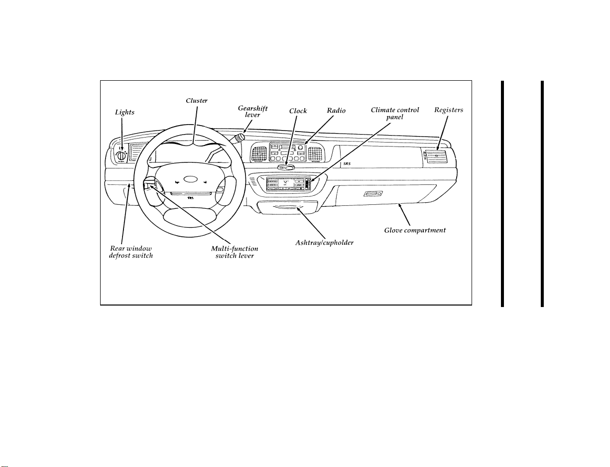
Crown Victoria instrument panel
7
Instrumentation
Page 11

The instrument panel (dashboard) on your
vehicle is divided into several different sections.
The illustrations on the following pages show
the major parts of the instrument panel that are
described in this chapter. Some items shown
may not be on all vehicles.
Your vehicle is equipped with one of the
following clusters:
a mechanical cluster
❑
an electronic cluster
❑
8
Page 12
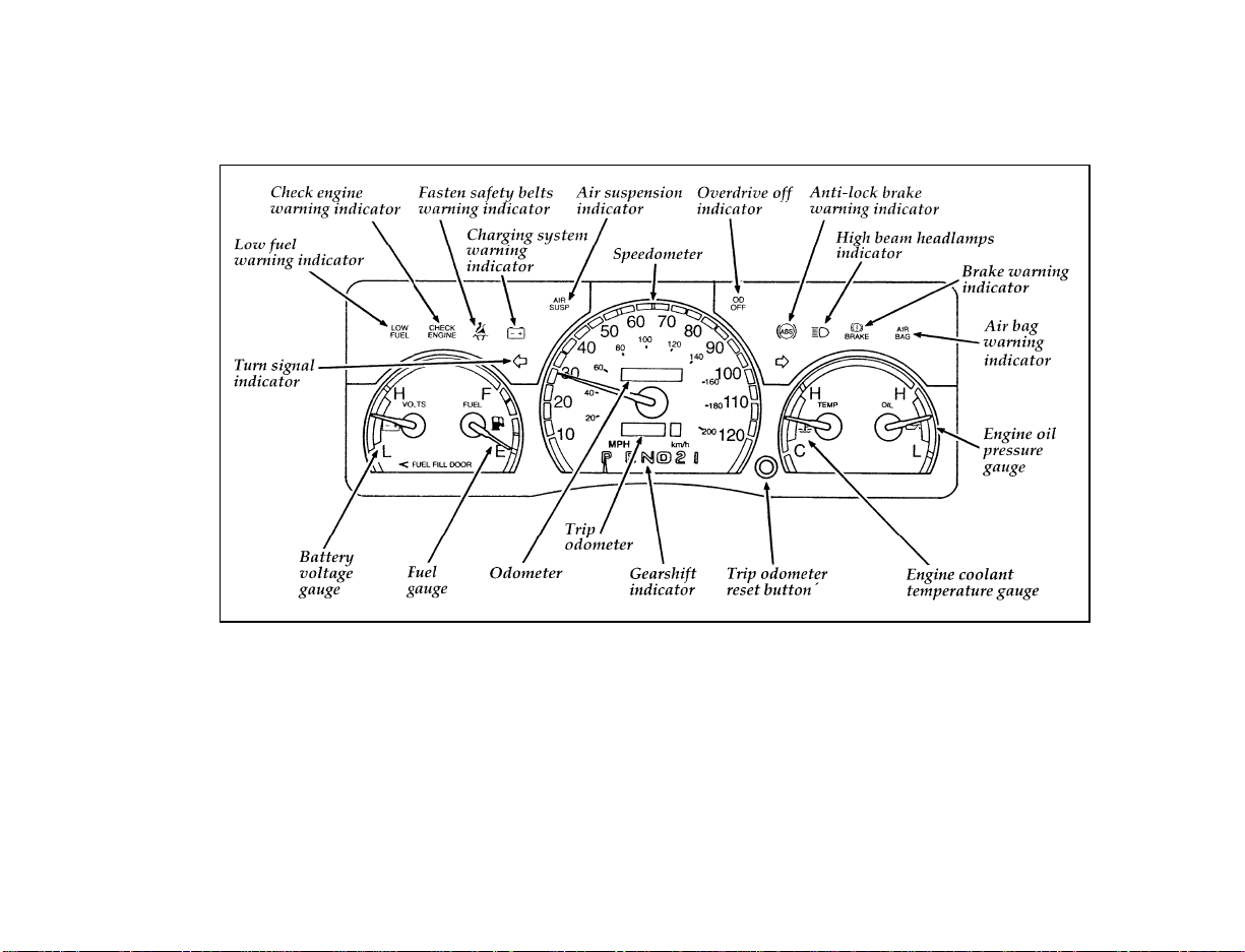
The mechanical cluster
9
Page 13
The following warning lights and gauges are on
the mechanical cluster. All of the warning lights
and gauges alert you to possible problems with
your vehicle. Some of the lights listed are
optional. The following sections detail what each
of these indicators means.
Brake System Warning Light
The warning light for the brakes can show two
things — that the parking brake is not fully
released, or that the brake fluid level is low in
the master cylinder reservoir. If the fluid level is
low, the brake system should be checked by a
qualified service technician.
The brake system warning light
This light comes on when the parking brake is
set, or if it is not set, it comes on briefly when
you turn the ignition key to START. It normally
goes off shortly after the engine starts and you
release the parking brake. If the light stays on
after you have fully released the parking brake,
have the hydraulic brake system serviced.
RWARNING
The BRAKE light indicates that the brakes
may not be working properly. Have the
brakes checked immediately.
10
Page 14
Anti-Lock Brake System Light
(If equipped)
This warning light will go on each time you
start your vehicle. If it remains on for longer
than five seconds, you should shut off your
engine and restart. If the anti-lock brake light
stays on, this indicates that the anti-lock feature
is disabled and should receive immediate
attention by a qualified service technician.
Normal braking is not affected unless the brake
warning light is also lit.
The Anti-Lock Brake System has self-check
capabilities. As previously described, the system
turns on the anti-lock light each time you start
your engine. After the engine is started and the
anti-lock light is out, the system performs
another test the first time the vehicle reaches
14 mph (22 km/h). The system turns on the
Anti-Lock Brake System (ABS) pump motor for
approximately 1/2 second. At this time a
mechanical noise may be heard. This is a normal
part of the self-check feature. If a malfunction is
found during this check the anti-lock light will
come on.
The anti-lock brake system light
11
Page 15
RWARNING
If the anti-lock brake system warning
light remains on or comes on while
driving, have the braking system checked
by a qualified service technician as soon
as possible.
NOTE: If a fault occurs in the anti-lock
system, and the brake warning light is
not lit, the anti-lock system is disabled
but normal brake function remains
operational.
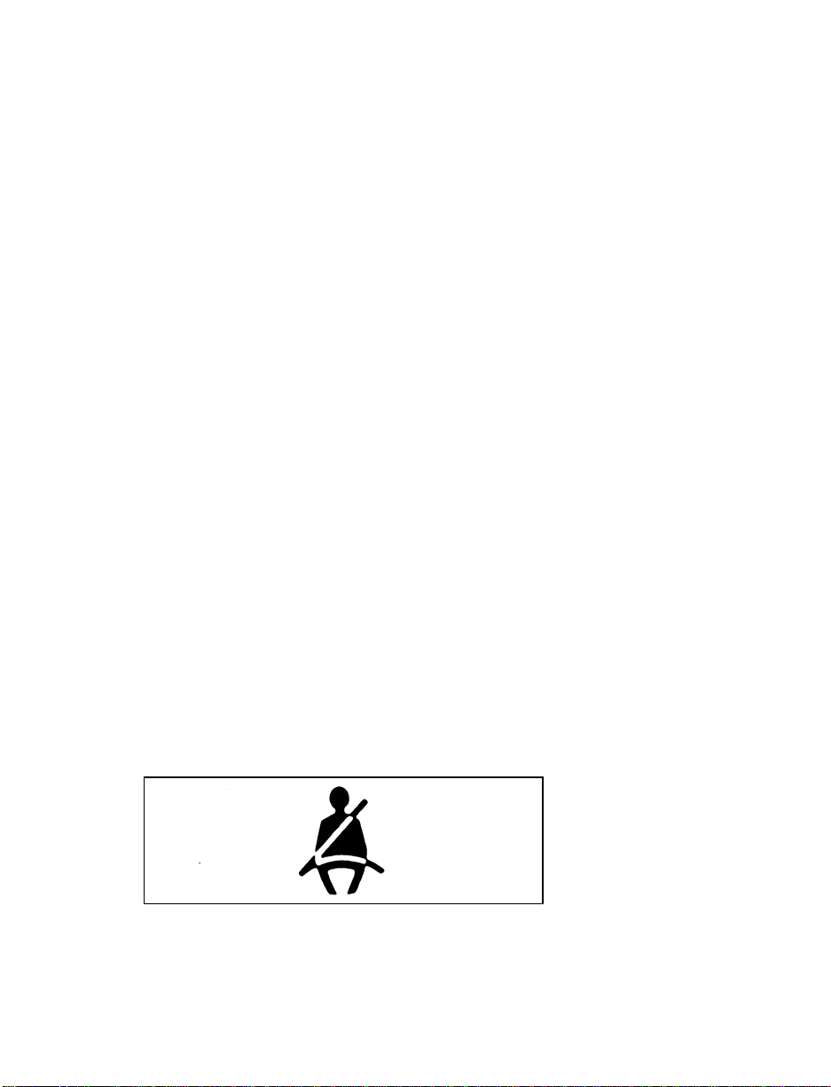
Safety Belt Warning Light and Chime
This warning light and chime remind you to
fasten your safety belt. The following conditions
will take place:
If the driver’s safety belt is not buckled when
❑
the ignition is turned to the ON position, the
light will turn on for 1 to 2 minutes and the
chime will sound for 4 to 8 seconds.
If the driver’s safety belt is buckled while the
❑
light is on or the chime is sounding, both the
light and the chime will turn off.
If the driver’s safety belt is buckled before the
❑
ignition is turned to the ON position, neither
the light nor the chime will turn on.
The safety belt warning light
12
Page 16
Air Bag Readiness Light
The air bag system uses a readiness light and a
tone to indicate the condition of the system. The
readiness light is in the instrument cluster. When
you turn the ignition key to the ON position,
this light will light up for six (6) seconds and
then turn off. This indicates that the system is
operating normally. NOTE: Regularly scheduled
maintenance of the air bag system is not
required.
If the light fails to illuminate, continues to flash,
remains on, or you hear a beeping sound, have
the system serviced at your Ford or
Lincoln-Mercury dealer immediately.
The air bag readiness light
Charging System Light
This light indicates that your battery is not being
charged and that you need to have the electrical
system checked.
The charging system light
13
Page 17
This light illuminates every time you turn the
ignition to the ON or START position (engine
off). The light should go off when the engine
starts and the alternator begins to charge.
If the light stays on or illuminates when the
engine is running, have the electrical system
checked as soon as possible.
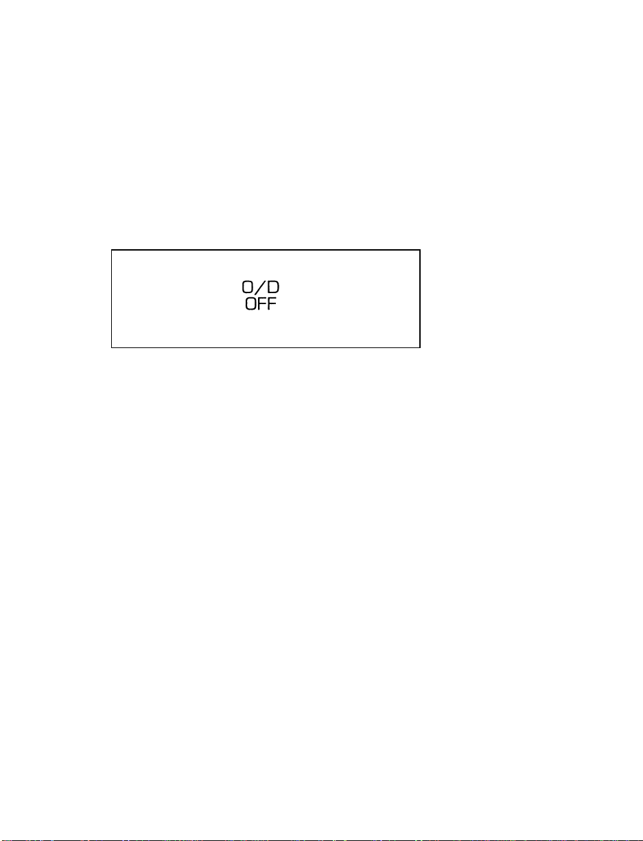
Overdrive Off Indicator
The overdrive off indicator light
This light tells you that the Transmission Control
Switch (TCS) has been pushed. When the light is
on, the transmission will not shift into overdrive.
Depressing the button will return the vehicle to
“overdrive on” mode. The transmission will be
in the “overdrive on” mode when the vehicle is
started even if the O/D OFF mode was selected
when the vehicle was last shut off.
NOTE: If the light does not come on when the
TCS is depressed or if the light flashes
when you are driving, have your
vehicle serviced at the first
opportunity. If this condition persists,
damage could occur to the
transmission.
14
Page 18
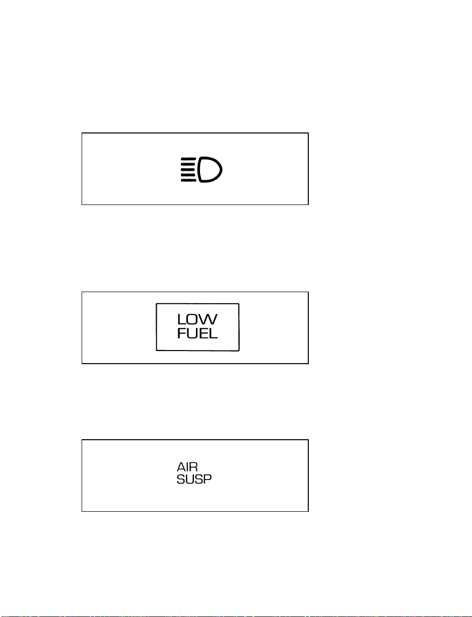
High Beam Light
This light illuminates when the headlamps are
turned to high beam or when you flash the
lights.
The high beam light
Low Fuel Alert Light
This light comes on when your fuel gauge
indicates between 1/8 and 1/16 of a tank. Your
car must be turned to ON for this light to come
on.
The low fuel alert light
Air Suspension Light (If equipped)
This light tells you if the air suspension needs
repair or if the air suspension switch (in the
trunk on the right side) is OFF.
The air suspension light
15
Page 19
Normally, the light will glow momentarily as
you turn the ignition key to the ON position. If
it glows continuously:
1. Safely pull off the road as soon as possible.
Turn the ignition key from ON to OFF and
ON again.
2. If the light still glows, check to see if the air
suspension switch is OFF. If it is OFF, push
the switch ON. If it is ON, push the switch
OFF and have the system checked as soon as
possible.
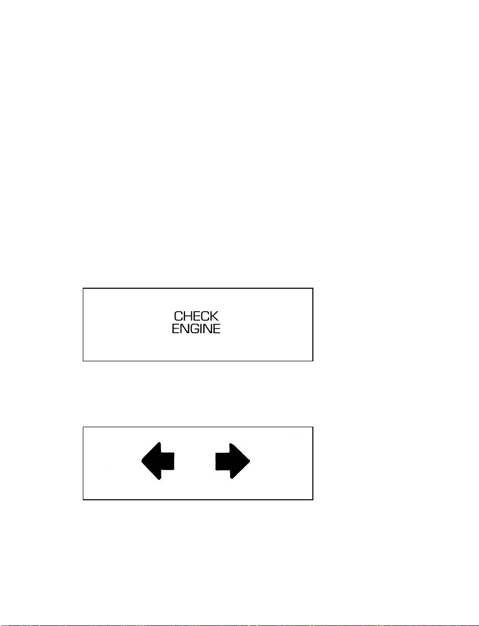
Check Engine Warning Light
This light illuminates when the engine’s
Emission Control System requires service. It will
also illuminate when the ignition key is in the
ON position and the engine is off.
The check engine warning light
Turn Signal Indicator Lights
The turn signal arrow will flash to indicate the
direction in which you are going to be turning.
The turn signal indicator light
16
Page 20
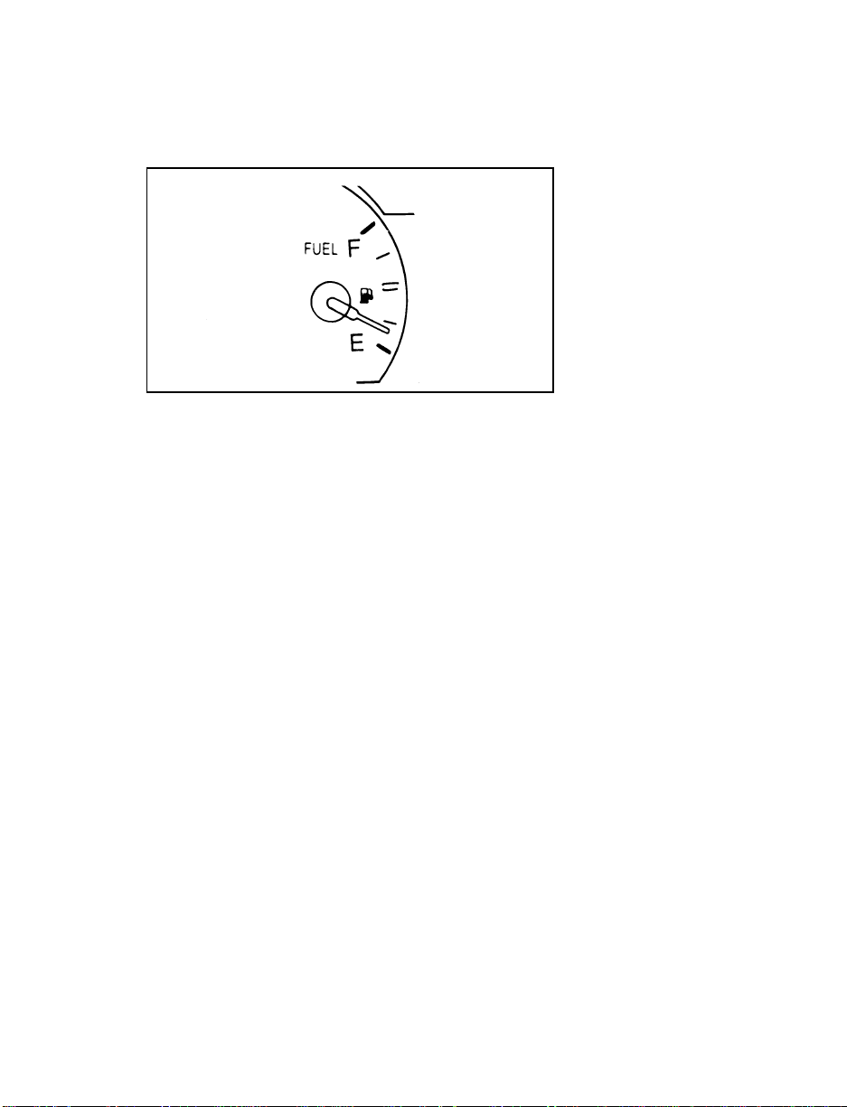
Fuel Gauge
The fuel gauge
The fuel gauge displays approximately how
much fuel is in the fuel tank only when the
ignition switch is ON. For proper fuel gauge
indication after adding fuel, turn the ignition
switch OFF while refueling the vehicle.
The fuel gauge indicator may vary slightly when
the vehicle is in motion. The most accurate
reading is obtained with the vehicle on level
ground.
With ignition switch OFF, the fuel gauge
indicator may drift from the ignition switch ON
position.
When you turn the ignition key to the ON or
ACC position, all the display segments will light
up, then go off for a second indicating the gauge
is working. Then the gauge will show you how
much fuel you have in the tank.
Engine Coolant Temperature Gauge
This gauge indicates the temperature of the
engine coolant, not the coolant level. If the
coolant is not at its proper level or mixture, the
gauge indication will not be accurate.
17
Page 21
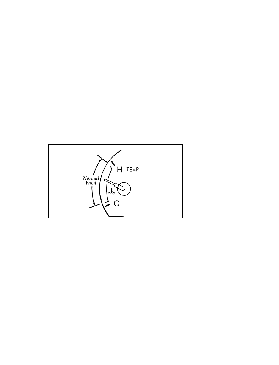
The pointer moves from the C (cold) mark into
the normal band as your engine coolant warms
up. Under normal driving conditions, the pointer
should stay in the normal band. It is acceptable
for the pointer to fluctuate within the normal
band under normal driving conditions, and
under certain driving conditions such as, heavy
stop and go traffic, or driving up hills in hot
weather, for the pointer to indicate at the top of
the normal band.
If, under any circumstances, the pointer moves
above the normal band, the engine is
overheating and continued operation may cause
engine damage.
The engine coolant temperature gauge
If your engine overheats:
1. Pull off the road as soon as safely possible.
2. Turn off the engine.
3. Let the engine cool. DO NOT REMOVE
COOLANT SYSTEM FILL CAP UNTIL
THE ENGINE IS COOL.
18
Page 22

4. Check the coolant level following the
instructions on checking and adding coolant
to your engine, see Engine Coolant in the
Index. If you do not follow these
instructions, you or others could be injured.
If the coolant continues to overheat, have the
coolant system serviced.
Speedometer
The speedometer tells you how many miles
(kilometers) per hour your vehicle is moving.
Odometer
The odometer tells you the total number of miles
(kilometers) your vehicle has been driven.
Trip Odometer
If you want to track your mileage up to 999.9
miles (kilometers), use the trip odometer. Simply
set the trip odometer to zero by pressing the
reset control firmly when beginning the distance
you wish to measure.
Since the trip odometer displays distance
independent of the odometer it will not always
advance to the next mile (kilometer) at the same
time as the odometer.
Battery Voltage Gauge
This gauge shows you the battery voltage when
the ignition key is in the ON position.
If the battery is operating under cold weather
conditions, the pointer may indicate in the upper
range of the normal band while the battery is
charging. If you are running electrical accessories
with the engine off or idling at a low speed, or
the battery is not fully charged, the pointer may
move toward the lower end of the normal band.
19
Page 23
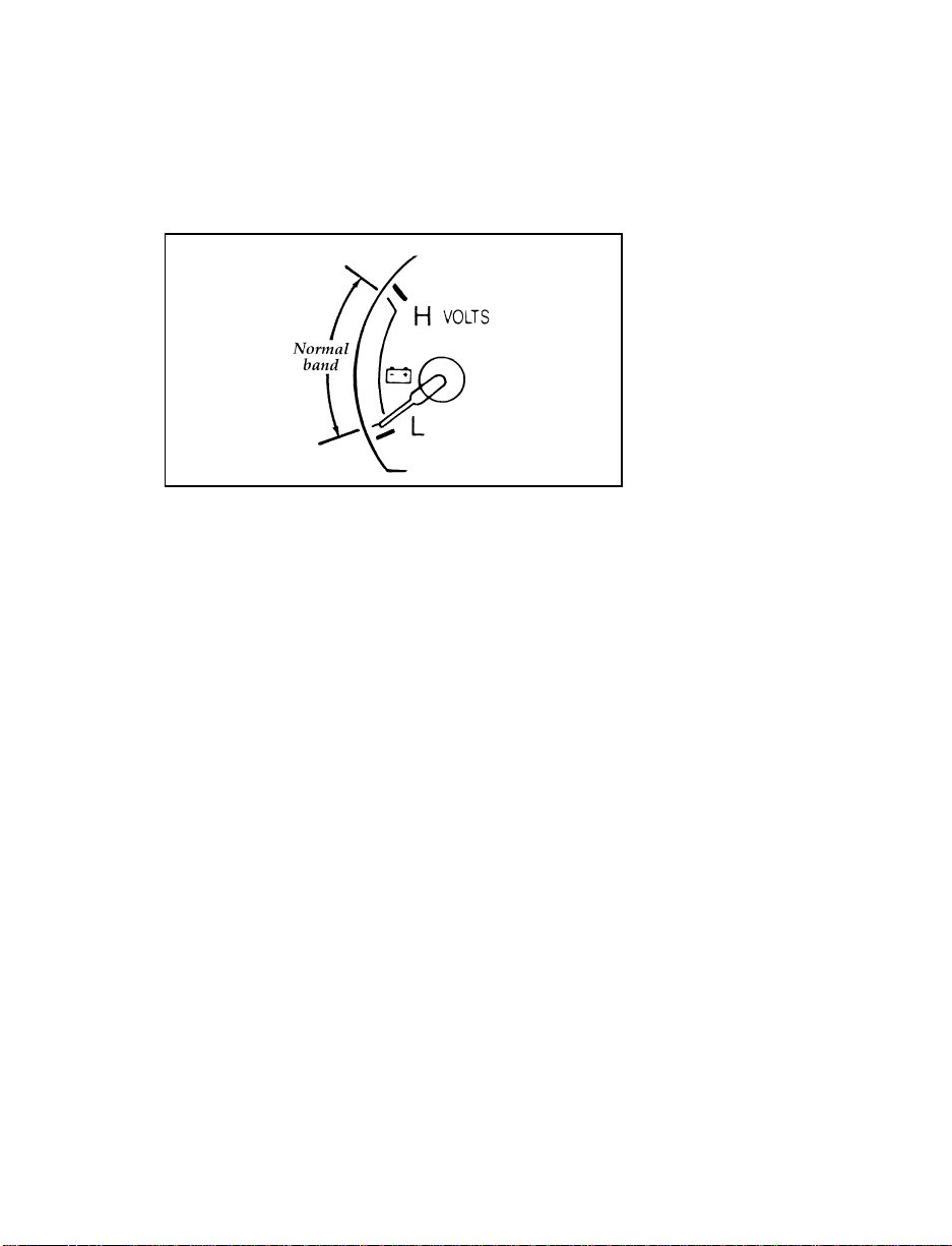
If it stays outside the normal band, have your
vehicle’s electrical system checked as soon as it
is safely possible.
The battery voltage gauge
Engine Oil Pressure Gauge
This gauge indicates the engine oil pressure, not
the oil level. However, if your engine’s oil level
is low, it could affect the oil pressure. With the
engine running, the pointer should move into
the normal band. If the pointer drops below the
normal band while the engine is running, you
have lost oil pressure and continued operation
will cause severe engine damage.
If you lose engine oil pressure:
1. Pull off the road as soon as safely possible.
2. Shut off the engine immediately or severe
engine damage could result.
3. Check the engine’s oil level, following the
instructions on checking and adding engine
oil, see the Engine Oil in the Index. If you do
not follow these instructions, you or others
could be injured. To assure an accurate
reading, your car should be on level ground.
20
Page 24

4. If the level is low, add oil as necessary
before you start the engine again. Do not
overfill. Do not operate the engine if the
pointer in the oil pressure gauge is below
the normal band, regardless of the oil level.
Contact your nearest dealer for further
service actions.
For more information about adding oil, see
Engine Oil Recommendations in the Index.
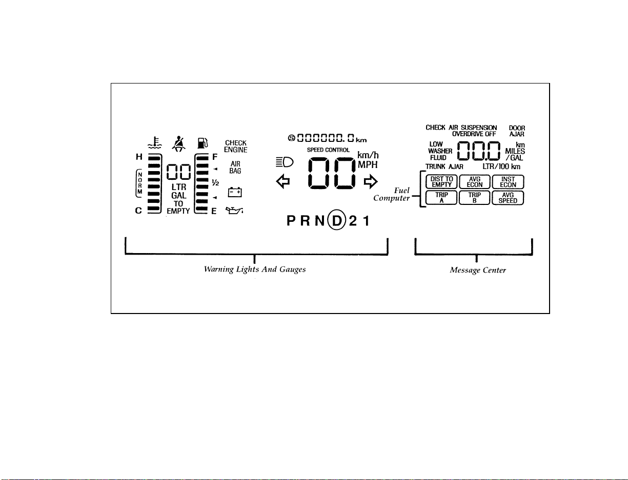
The electronic cluster works only when your
ignition is in the ON position. Each time you
start your vehicle, the displays go through a
self-test by flashing on and off once before the
actual readings are displayed. (Neither the turn
signals nor the high beam indicator light will
flash like the other indicators do for the
self-test.) Some of the warning lights will flash
on and remain on (will not immediately flash
off) until the normal cluster display is lit. This
self-test is used to indicate that all of the
warning/indicator lights are working properly.
Your electronic cluster tells you about the
condition of your vehicle by using two types of
equipment:
warning lights and gauges
❑
message center
❑
21
Page 25
22
Electronic cluster
Page 26
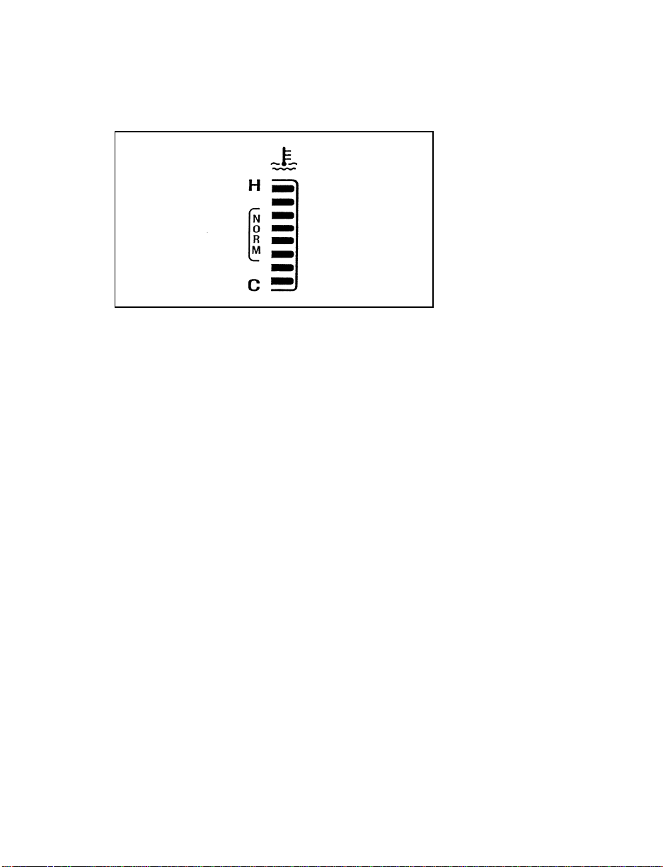
Engine Coolant Temperature Gauge
The engine coolant temperature gauge
This gauge indicates the engine coolant
temperature not the coolant level. If the coolant
is not at its proper level or mixture, the gauge
indication will not be accurate. It is identified by
a thermometer symbol, an “H” (hot), and a “C”
(cold). The “NORM” indicates the normal
operating range. The bars will move into the
normal operating range as the engine coolant
warms up. It is acceptable under certain driving
conditions such as, heavy stop and go traffic, or
driving up hills in hot weather, for the gauge to
indicate at the top of the NORM band.
If, under any circumstance, the pointer moves
above the NORM band, the temperature symbol
flashes and a tone will sound to alert the driver
that the engine coolant is overheating and
continued operation may cause engine damage.
If your engine overheats:
1. Pull off the road as soon as it is safely
possible.
2. Turn off the engine. If you do not stop the
engine as soon as safely possible, severe
engine damage could result.
23
Page 27
3. Let the engine cool. DO NOT REMOVE
COOLANT SYSTEM FILL CAP UNTIL
THE ENGINE IS COOL.
4. Check the coolant level following the
instructions on checking and adding coolant
to your engine, see Engine Coolant in the
Index. If you do not follow these
instructions, you or others could be injured.
If the coolant continues to overheat, have the
coolant system serviced.
If only the top two and bottom two bars appear
on the gauge, then the system is indicating that
it requires servicing. Contact your dealer for
service as soon as possible.
Safety Belt Warning Light and Chime
This warning light and chime remind you to
fasten your safety belt. The following conditions
will take place:
If the driver’s safety belt is not buckled when
❑
the ignition is turned to the ON position, the
light will turn on for 1 to 2 minutes and the
chime will sound for 4 to 8 seconds.
If the driver’s safety belt is buckled while the
❑
light is on or the chime is sounding, both the
light and the chime will turn off.
If the driver’s safety belt is buckled before the
❑
ignition is turned to the ON position, neither
the light nor the chime will turn on.
The safety belt warning light
24
Page 28
High Beam Light
This light illuminates when the headlamps are
turned to high beam or when you flash the
lights.
The high beam light
Check Engine Warning Light
This light illuminates when the engine’s
Emission Control System requires service. It will
also illuminate when the ignition key is in the
ON position and the engine is off.
The check engine warning light
Air Bag Readiness Light
The air bag system uses a readiness light and a
tone to indicate the condition of the system. The
readiness light is in the instrument cluster. When
you turn the ignition key to the ON position,
this light will light up for six (6) seconds and
then turn off. This indicates that the system is
operating normally. NOTE: Regularly scheduled
maintenance of the air bag system is not
required.
25
Page 29
If the light fails to illuminate, continues to flash,
remains on, or you hear a beeping sound, have
the system serviced at your Ford or
Lincoln-Mercury dealer immediately.
The air bag readiness light
Charging System Warning Light
This light comes on when you turn your ignition
key from OFF to ON. The light should go out
when the engine starts and the alternator begins
to charge.
If this light stays on or comes on while your
engine is running, this tells you that your
battery is not being charged and that you need
to have the electrical system checked as soon as
possible.
The charging system warning light
26
Page 30
Engine Oil Pressure Light
The engine oil pressure light
This light indicates the engine oil pressure, not
the oil level. However, if your engine’s oil level
is low, it could affect the oil pressure. The light
should come on every time your ignition key is
turned to ON or START, and should go out
when the engine starts. If the light stays on or
turns on while the engine is running, you have
lost oil pressure and continued operation will
cause severe engine damage.
If you lose engine oil pressure:
1. Pull off the road as soon as safely possible.
2. Shut off the engine immediately. If you do
not stop the engine as soon as safely
possible, severe engine damage could result.
3. Check the engine’s oil level, following the
instructions on checking and adding engine
oil, see Engine Oil in the Index. If you do
not follow these instructions, you or others
could be injured. To assure an accurate
reading, your vehicle should be on level
ground.
4. If the level is low, add only as much oil as
necessary before you start the engine again.
Do not overfill. Do not operate the engine if
the light is on, regardless of the oil level.
Contact your nearest dealer for service as
soon as possible.
27
Page 31

For more information about adding oil, see
Adding engine oil in the Maintenance and Care
chapter of this guide.
Turn Signal Indicator Lights
The turn signal arrow will flash to indicate the
direction in which you are going to be turning.
The turn signal indicator lights
Speed Control Indicator Light
This light comes on when the speed control
system is actively maintaining the set speed. It
will go off when the brakes are used or if the
speed control is turned off.
The speed control indicator light
This light does not indicate any problems but is
only a convenience to tell when the speed
control is active.
28
Page 32

Fuel Gauge
The fuel gauge
The fuel gauge tells you approximately how
many gallons/liters of fuel you have in the tank.
When your tank reaches 1/8 or approximately 2
gallons (8 liters), a flashing fuel pump will
appear.
Turn the ignition switch off while fueling to
obtain an accurate fuel gauge indication.
NOTE: At least 2.5 gallons (9.5 liters) of fuel
must be added for the fuel gauge to
immediately show the new level of
fuel. If less than 2.5 gallons (9.5 liters)
of fuel is added, the gauge will reach
the new level slowly.
If the fuel gauge displays only the top two bars
and the bottom two bars, or, if fuel remaining or
distance to empty functions display CO or CS,
then there is a problem. Take your vehicle in for
service.
29
Page 33

FUEL REMAIN — Fuel Remaining for the
Electronic Cluster
This function shows you how many gallons
(liters) of fuel you have left in the fuel tank.
If your fuel level is above 20 gallons (76 liters),
the letter “F” (full) will appear on the display.
But if your fuel level has dropped to below 1
gallon (4 liters), the letter “E” (empty) will
appear in the display.
Because of factors like rounding of numbers and
fuel movement in the tank, your fuel gauge and
the service station fuel pump readings may
disagree slightly.
A problem is indicated if the fuel gauge bar
graph displays only the top two and bottom two
bars and the message center display for Distance
To Empty or Fuel Remaining functions display
the letters “CO” or “CS”. If this happens, contact
your dealer for service as soon as possible.
Speedometer
The speedometer tells you how many miles
(kilometers) per hour your vehicle is moving. It
indicates the speed up to 120 mph or up to
195 km/h.
You can press the E/M (English/Metric) button
located just below the message center display to
show the speed you are going in either miles
per hour or kilometers per hour.
30
Page 34

The speedometer
Odometer
The odometer tells you the total number of miles
or kilometers your vehicle has been driven. If
the cluster is replaced, and the accumulated
mileage on the odometer is unknown, the
replacement cluster will have the circled “S”
illuminated with zero miles on the odometer. If
the actual vehicle mileage can be verified, then
an authorized service center can program the
actual mileage into the odometer of the
replacement cluster. The actual mileage (if
known) or an estimated mileage (if unknown) is
shown on a label affixed on the door pillar.
Press the E/M (English/Metric) button located
just below the message center display to show
miles or kilometers.
If the odometer displays the word “ERROR”
contact your dealer for service.
The Electronic Message Center
Along with information the warning lights and
gauges provide, the electronic message center
lets you:
see problems such as Door Ajar, Air
❑
Suspension, Trunk Ajar, Washer Fluid
see how many miles/kilometers you can
❑
drive with the fuel remaining in your tank
31
Page 35

see when overdrive has been turned off
❑
monitor your average fuel economy
❑
monitor your instantaneous fuel economy
❑
check the distance you have travelled during
❑
a trip on either Trip A or Trip B
monitor your average speed
❑
Message center display showing all segments on
All of the message center functions are
controlled by the three switches located just
below the message center display:
E/M — Changes the electronic instrument
❑
cluster display to read in either English or
Metric units.
Reset — Sets the selected function to zero (if
❑
resettable).
Select — Selects the function. This is a dual
❑
action switch, the right side advances function
to the right, the left side advances function to
the left.
32
Page 36

Buttons for the message center
How to use the message center
To reset any function:
1. Push either the right or left side of the
SELECT button to choose the function you
would like to set.
2. Push the RESET button and the selected
message center function will be reset to zero.
(The only functions which can be reset to
zero are: AVG ECON, TRIP A or TRIP B,
and AVG SPEED.)
What the message center functions can
show you
DIST TO EMPTY — Distance to Empty
(DTE)
Message center display showing the DTE function selected
33
Page 37

This function estimates how many miles or
kilometers you can drive with the fuel remaining
in your tank under standard driving conditions.
Remember to turn off the ignition when filling
up with fuel. Otherwise, the display will not
show the addition of fuel for a few miles.
NOTE: At least 2.5 gallons (9.5 liters) of fuel
must be added for the fuel gauge to
imediately show the new level of fuel.
When you have approximately 50 miles (80 km)
left before you run out of fuel, the DTE function
will flash for five (5) seconds and sound a tone
for one (1) second. The message center will
remain in the DTE function until you push the
select button to change it. This low fuel warning
also happens at 25 miles (40 km), and 10 miles
(16 km).
Displayed DTE will not be equal to AVG ECON
multiplied by the FUEL REMAIN value. This is
because DTE is calculated using a method that
takes into consideration the fuel economy of the
last 500 miles (800 Km) driven.
If “CO” or “CS” is displayed, this means that
there is a problem with the fuel indication
system and you should contact your dealer for
service as soon as possible.
34
Page 38

AVG ECON — Average Fuel Economy
Select this function to display your average fuel
economy in miles per gallon or liters per
100 kilometers. Your message center computes
this figure using the distance traveled and fuel
used information. If you want to reset this
function, press the RESET button while the
average fuel economy feature is displayed.
The average shown is the average since the
reset.
If you calculate your average fuel economy by
dividing miles traveled by gallons used, your
figure may be different than displayed because
of:
Your vehicle not being perfectly level during
❑
fill-up
Differences in the automatic shut-off points
❑
on the fuel pumps at service stations
Variations in top-off procedure from one
❑
fill-up to another
Rounding of the displayed values to the
❑
nearest 0.1 gallon (liters) on the fuel gauge.
35
Page 39

INST ECON — Instantaneous Fuel
Economy
Select this function to calculate your
instantaneous fuel economy. Your instantaneous
fuel economy is the fuel economy you get at any
particular moment. For example, you can see
what your fuel economy is in heavy traffic or on
an open highway.
Your vehicle must be moving to calculate fuel
economy. When your vehicle is not moving,
instantaneous fuel economy is displayed at 0
miles per gallon or 99 liters per 100 kilometers.
When you are moving, the display may read
anything between 0 and 99 miles/gallon (1 to 99
L/km). Instantaneous fuel economy cannot be
reset.
TRIP A and TRIP B — Elapsed Distance
Traveled
These two functions of the message center allow
you to see how far you have traveled since you
last reset. Trip A and Trip B are completely
independent and must be reset individually.
36
Page 40

To reset either trip feature to zero, press the
RESET switch while a trip distance feature (Trip
A or Trip B) is displayed.
AVG SPEED — Average Speed
Select this function to display your average
speed in miles per hour or kilometers per hour.
Your vehicle must be moving to calculate your
average speed. When your vehicle is not
moving, the average speed is displayed at 0
miles per hour or 0 kilometers per hour.
Check Air Suspension Light (If equipped)
This light glows momentarily when the ignition
is turned to the ON position. With the ignition
on this light will remain on to indicate that the
air suspension switch (located in the trunk on
the right side) is off or to indicate a possible
system fault.
If the light is displayed while driving and the
air suspension switch is not turned off, safely
pull off the road as soon as possible. Turn the
37
Page 41

ignition switch from ON to OFF and to ON
again. If the light continues to be displayed turn
the air suspension switch (located in the trunk
on the right side) off and take your vehicle to a
dealership for service as soon as possible.
The check air suspension light
Overdrive Off Indicator
The overdrive off indicator light
This light tells you that the Transmission Control
Switch (TCS) has been pushed. When the light is
on, the transmission will not shift into overdrive.
Depressing the button will return the vehicle to
“overdrive on” mode. The transmission will be
in the “overdrive on” mode when the vehicle is
started even if the O/D OFF mode was selected
when the vehicle was last shut off.
NOTE: If the light does not come on when the
TCS is depressed or if the light flashes
when you are driving, have your
vehicle serviced at the first
opportunity. If this condition persists,
damage could occur to the
transmission.
38
Page 42

Low Washer Fluid Light
This light comes on when there is less than a
quarter of the container of washer fluid left.
With the ignition ON this light will flash five (5)
times and a tone will sound for one (1) second,
and then the light will remain on.
The low washer fluid light
Door Ajar Light
If one of the doors is not completely shut, this
light comes on when you turn the ignition to
ON. With the ignition on this light will flash
five (5) times and sound a tone for one (1)
second, and then the light will remain on.
The door ajar light
39
Page 43

Trunk Ajar Light
If the trunk is not completely closed, this light
comes on when you turn the ignition to ON.
With the ignition ON this light will flash five (5)
times and sound a tone for one (1) second, and
then the light will remain on.
The trunk ajar light
The following warning lights are on the
indicator lamp module. The following section
details what each of these indicators mean.
The indicator lamp module
40
Page 44

Anti-Lock Brake System Light
(If equipped)
This warning light will go on each time you
start your vehicle. If it remains on for longer
than 5 seconds, you should shut off your engine
and restart. If the anti-lock brake light stays on,
this indicates that the anti-lock feature is
disabled and should receive immediate attention
by a qualified service technician. Normal braking
is not affected unless the brake warning light is
also lit.
The Anti-Lock Brake System has self-check
capabilities. As previously described, the system
turns on the anti-lock light each time you start
your engine. After the engine is started and the
anti-lock light is out, the system performs
another test the first time the vehicle reaches
14 mph (22 km/h). The system turns on the
Anti-Lock Brake System (ABS) pump motor for
approximately 1/2 second. At this time a
mechanical noise may be heard. This is a normal
part of the self-check feature. If a malfunction is
found during this check the anti-lock light will
come on.
The anti-lock brake system light
41
Page 45

RWARNING
If the anti-lock brake system warning
light remains on or comes on while
driving, have the braking system checked
by a qualified service technician as soon
as possible.
NOTE: If a fault occurs in the anti-lock
system, and the brake warning light is
not lit, the anti-lock system is disabled
but normal brake function remains
operational.
Brake System Light
The warning light for the brakes can show two
things — that the parking brake is not fully
released, or that the brake fluid level is low in
the master cylinder reservoir. If the fluid level is
low, the brake system should be checked by a
qualified service technician.
The brake system light
42
Page 46

This light comes on when the parking brake is
set, or if it is not set, it comes on briefly when
you turn the ignition key to START. It normally
goes off shortly after the engine starts and you
release the parking brake. If the light stays on
after you have fully released the parking brake,
have the hydraulic brake system serviced.
RWARNING
The BRAKE light indicates that the brakes
may not be working properly. Have the
brakes checked immediately.
43
Page 47

45
Luxury Audio System (Analog)
Electronic Sound Systems
Page 48

46
Luxury Audio System (Digital)
Page 49

Using the Controls on Your New Radio
How to turn the radio on and off
Press the “VOL/PUSH ON” knob to turn the
radio on. Press again to turn it off.
How to adjust the volume
Turn the “VOL/PUSH ON” knob to the right to
increase the volume and to the left to decrease
the volume.
NOTE: If the volume level is set above a
certain listening level when the
ignition switch is turned off, when the
ignition switch is turned back on, the
volume will come back to a “nominal”
listening level. However, if the radio
power is turned off (with the
“VOL/PUSH ON” button), the volume
will remain in the position it was set
at when radio power is switched back
on (digital systems only).
Selecting the AM or FM frequency band
Push the “AM/FM” button to select the desired
frequency band. Pushing the “AM/FM” button
causes the frequency band to switch from “AM”
to “FM1” to “FM2” to “AM”, changing one band
to the next each time the button is pressed.
These functions are used with the station
memory buttons described under How to tune
radio stations.
47
Page 50

How to tune radio stations
There are four ways for you to tune in a
particular station. You can use the “TUNE”,
“SEEK”, “SCAN” or memory buttons.
Using the “TUNE” function
❑
You can change the frequency up or down
one increment at a time by pressing and
releasing either the leftbor rightaside of
the “TUNE” button. To change frequencies
quickly, press and hold down either the right
or left side of the “TUNE” button.
Manual tuning adjusts your radio to any
allowable broadcast frequency, whether or
not a station is present on that frequency.
(See All About Radio Frequencies in this
section.)
Using the “SEEK” function
❑
Press the rightaside of the “SEEK” button
to select the next listenable station up the
frequency band. Press the leftbside of the
button to select the next listenable station
down the frequency band. By holding the
button down, listenable stations can be
passed over to reach the desired station.
Using the “SCAN” function
❑
Pressing the “SCAN” button will begin the
scan mode up the frequency band, stopping
on each listenable station for approximately
five seconds.
To stop the scan mode on the presently
sampled station, press the “SCAN” button
again.
48
Page 51

Setting the station MEMORY PRESET buttons
❑
Your radio is equipped with 6 station
memory buttons. These buttons can be used
to select up to 6 preset AM stations and 12
FM stations (6 in FM1 and 6 in FM2)
Follow the easy steps below to set these buttons
to the desired frequencies:
1. Select a band, then select a frequency.
2. Press one of the memory preset buttons and
hold the button until the sound returns. That
station is now held in memory on that
button.
3. Follow the two steps above for each station
memory preset button you want to set.
Using the Automatic Memory Store feature
(“AUTOSET”)
If the memory buttons have been set, either by
using the Auto Memory Load feature or if you
have set them manually, the system is prepared
to let you use a convenient feature called
Automatic Memory Store.
With Auto Memory Store, you can continually
set strong stations into your memory buttons
without losing your originally set stations. Your
radio will automatically set your memory
buttons to the strong local stations.
Activate Auto Memory Store by pushing the
“AUTOSET” button once. Your radio will set the
first six strong stations of the band you are in
(AM, FM1 or FM2) into the memory buttons.
The display will flash “AUTO” and display the
autoset icon “A” while the stations are being set
in the memory buttons.
49
Page 52

NOTE: If there are fewer than six strong
stations in the frequency band, the
remaining unfilled buttons will store
the last strong station detected on the
band. After all stations have been
filled, the radio will begin playing the
station stored on memory button 1.
To deactivate the Auto Memory Store mode and
return to the manually-set memory button
stations, simply push the “AUTOSET” button.
Display will show “AUTO” then “OFF”. The
next time Auto Memory Store is activated on
that band, the radio will store the next set of six
strong stations.
Adjusting the tone balance of your radio
Increasing or decreasing bass and treble
❑
response
Push the “BASS/TREB” popout knob to gain
access to the bass and treble controls. Bass
control allows you to adjust the lower, bass
frequencies to your preference. The outer ring
of the “BASS/TREB” knob adjusts the bass
(turn clockwise to increase bass;
counterclockwise to decrease bass).
Treble control allows you to adjust the
higher, treble frequencies of your radio to
your preference. The inner ring of the
“BASS/TREB” knob adjusts the treble (turn
clockwise to increase treble; counterclockwise
to decrease treble).
50
Page 53

Adjusting speaker balance and speaker fader
❑
Push the “BAL/FADE” popout knob to gain
access to the speaker balance and fader
controls. Balance control allows you to adjust
the sound distribution between the right and
left speakers. The outer ring of “BAL/FADE”
knob adjusts the speaker balance control.
(Turn clockwise to shift the sound to the
right speakers, and turn counterclockwise to
shift the sound to the left speakers.)
Fade control allows you to adjust the sound
distribution between the front and rear
speakers. The inner ring of the “BAL/FADE”
knob adjusts the speaker fader. (Turn
clockwise to shift the sound to the rear
speakers, and turn counterclockwise to shift
the sound to the front speakers.)
Using the Digital Signal Processing (DSP)
Feature
Push the “DSP” button to activate the feature.
The display will indicate which signal mode is
in effect. To change the signal mode press either
the leftbor rightaside of the selector button
(located under the “DSP” button).
The following signal modes may be selected:
1. “HALL” — Rectangular concert hall capacity
of about 2,000.
2. “CHURCH” — Church with a high vault.
3. “JAZZ” — Jazz club with clearly reflected
sounds.
4. “STADIUM” — Outdoor stadium with a
capacity of about 30,000.
5. “NEWS” — “Voice-only” type of sound with
a limited audio band.
51
Page 54

To deactivate the DSP feature, press the “DSP”
button again.
Your Antenna
Antennas for both AM and FM reception are
hidden in the back glass of your vehicle. There
is an internal antenna module that will switch
between AM and FM, when bands are changed,
for maximum reception performance.
NOTE: Do not attempt to adapt any other type
of antenna system to your audio
system.
Using the Controls of Your Cassette Tape
Player
NOTE: Radio power must be on to use the
cassette tape player.
How to insert a tape
Your cassette tape player is equipped with
power loading. Once you insert a tape and push
slightly (with the open edge to the right), the
loading mechanism draws the tape the rest of
the way in and play will begin after a
momentary tape tightening process. Display
indicates “TAPE” while tape is playing.
If the player is in the tape mode but not in play,
pressing the “TAPE” button will activate play. If
the “TAPE” button is pressed with no tape
inserted, the display will flash “NO TAPE”.
52
Page 55

How to locate a desired track on the tape
There are six ways to quickly locate a desired
selection on the tape. You can use the fast
forward, rewind, Blank Skip, “SEEK”, “SCAN”
or “SIDE 1-2” functions. Following are brief
descriptions of each:
Fast forwarding the tape
❑
To fast forward the tape, press the “FF”
button. The radio will play while the tape is
in fast forward. The light above the “FF”
button will blink while in the fast forward
mode. Press “FF” again or press the “TAPE”
button to stop fast forwarding. At the end of
the tape, the direction automatically reverses
and plays the other side of the tape.
Rewinding the tape
❑
To rewind the tape, press the “REW” button.
The radio will automatically begin playing
while the tape is rewinding. The light above
the “REW” button will blink while in the
rewind mode. Press “REW” again or press
the “TAPE” button to stop rewinding.
Using the “SEEK” function with your cassette
❑
tape player
While in the tape mode, push the right
side of the “SEEK” button to seek forward to
the next selection on the tape. Push the left
side to restart a currently playing tape
b
selection.
Using the “Blank Skip” function with your
❑
cassette tape player
Press the “Blank Skip” button to activate the
blank skip mode. After approximately 20
seconds of blank program, the tape will seek
forward to the next program.
a
53
Page 56

Using the “SCAN” function with your
❑
cassette tape player
Pushing the “SCAN” button will begin the
forward scan mode on the tape currently
playing, stopping on each tape selection for
approximately eight seconds.
To stop the scan mode on the presently
sampled tape selection, press the “SCAN”
button or the “TAPE” button.
How to change the side of the tape being
❑
played
The alternate side of the tape can be selected
by pressing the “SIDE 1-2” button.
How to eject the tape
To stop the tape and eject the cassette, press the
“EJECT” button. The tape will eject only when
in the tape mode. The cassette cannot be ejected
when the radio is playing an “AM” or “FM”
station. The system will revert to radio mode
when the cassette is ejected.
Using the DolbyH B noise reduction feature
NOTE: Noise reduction system manufactured
under license from Dolby Labs
Licensing Corporation. “Dolby” and
double-D symbol are trademarks of
Dolby Laboratories Licensing
Corporation.
Push the k button to activate. When
activated, the light above the k button will be
illuminated.
54
Page 57

Tape error messages
Your cassette tape player is equipped to
diagnose certain problems you may experience.
Error codes are as follows:
TD E1 — Radio tries to change sides of tape 3
times in a 10 second span. Push “EJECT” and
try another tape. If problem persists, refer
problem to qualified personnel for service.
TD E2 — Tape eject failure. Radio tries to eject
tape and it will not eject. Push “EJECT” to eject
tape. If the tape will not eject, refer problem to
qualified personnel for service.
TD E3 — Loading error. Push “EJECT” to eject
tape. Reload tape. If the same error code appears
in the display, try another tape.
Tips on Caring for the Cassette Player and
Tapes
In order to keep your cassette tape player
performing the way it was meant to, read and
follow these simple precautions:
Using a Ford or equivalent cassette cleaning
❑
cartridge to clean the tape player head after
10-12 hours of play will help maintain the
best playback sound and proper tape
operation.
Only cassettes that are 90 minutes long or
❑
less should be used. Tapes longer than 90
minutes are thinner and subject to breakage
or may jam the tape player mechanism.
55
Page 58

Protect cassettes from exposure to direct
❑
sunlight, high humidity and extreme heat or
cold. If they are exposed to extreme
conditions, allow them to reach a moderate
temperature before playing.
If a tape is loose inside the cassette, tighten it
❑
before playing by putting your finger or a
pencil into one of the holes and turning the
hub until the tape is tight.
Loose labels on cassette tapes can become
❑
lodged in the mechanism. Remove any loose
label material before inserting a cassette.
Do not leave a tape in the cassette tape
❑
player when not in use. High heat in the
vehicle can cause the cassette to warp.
56
Page 59

57
Electronic Search Radio
Page 60

58
Electronic Search Cassette
Page 61

Cassette Radio
Using the Controls on Your New Radio
How to turn the radio on and off
Press the “VOL/PUSH ON” knob to turn the
radio on. Press again to turn it off.
How to adjust the volume
Turn the “VOL/PUSH ON” knob to the right to
increase the volume and to the left to decrease
the volume. Bars illuminate in the display to
show relative volume level.
NOTE: If the volume level is set above a
certain listening level when the
ignition switch is turned off, when the
ignition switch is turned back on, the
volume will come back to a “nominal”
listening level. However, if the radio
power is turned off, the volume will
remain in the position it was set at
when radio power was switched off.
Selecting the AM or FM frequency band
Push the “AM/FM” button to select the desired
frequency band or to stop/store cassette tape
(when in cassette mode). Pushing the button
more than once will alternate between AM, FM1
and FM2. These functions are used with the
station memory buttons described under How to
tune radio stations.
59
Page 62

How to tune radio stations
There are four ways for you to tune in a
particular station. You can manually locate the
station using the “SCAN/TUNE” button,
“SEEK” the station, “SCAN” to the station or
select the station by using the memory buttons,
which you can set to any desired frequency.
These four methods are described below.
Using the “TUNE” function
❑
You can change the frequency up or down
one increment at a time by pressing and
releasing either the leftbor rightaside of
the “TUNE” button.
Manual tuning adjusts your radio to any
allowable broadcast frequency, whether or
not a station is present on that frequency.
(See All About Radio Frequencies in this
section.)
Using the “SEEK” function
❑
This feature on your radio allows you to
automatically select listenable stations up or
down the frequency band. Press the right
side of the “SEEK” button to select the next
listenable station up the frequency band.
Press the leftbside of the button to select
the next listenable station down the
frequency band. By holding the button down,
listenable stations can be passed over to reach
the desired station.
a
60
Page 63

Using the “SCAN” function
❑
Pressing the “SCAN” button will begin the
scan mode up the frequency band, stopping
on each listenable station for approximately
five seconds.
To stop the scan mode on the presently
sampled station, press the “SCAN” button
again.
Setting the Station Memory Preset buttons
❑
Your radio is equipped with 6 station
memory buttons. These buttons can be used
to select up to 6 preset AM stations and 12
FM stations (6 in FM1 and 6 in FM2).
Follow the easy steps below to set these buttons
to the desired frequencies:
1. Select a band, then select a frequency.
2. Press one of the memory preset buttons and
hold the button until the sound returns. That
station is now held in memory on that
button.
3. Follow the two steps above for each station
memory preset button you want to set.
NOTE: If the vehicle’s battery is disconnected
the station memory preset buttons will
need to be reset.
61
Page 64

Adjusting the tone balance and speaker
output of your radio
Increasing or decreasing bass response
❑
Press the topcof the “BASS” button to
increase bass; press the bottomdof the
“BASS” button to decrease bass.
Increasing or decreasing treble response
❑
Press the topcof the “TREBLE” button to
increase treble; press the bottomdof the
treble button to decrease treble.
Adjusting speaker balance
❑
Balance control allows you to adjust the
sound distribution between the right and left
speakers. Press the topcof the “BAL”
button to shift the sound to the right
speakers, and press the bottomdof the
“BAL” button to shift the sound to the left
speakers.
Adjusting speaker fader
❑
Fade control allows you to adjust the sound
distribution between the front and rear
speakers. Press the topcof the “FADE”
button to shift the sound to the front
speakers, and press the bottomdof the
“FADE” button to shift the sound to the back
speakers.
NOTE: Illuminated bars in the display show
relative levels of bass and treble, and
positions of speaker balance and fader
functions (left to right, front to rear).
62
Page 65

Using the Controls of Your Cassette Tape
Player
NOTE: Radio power must be on to use the
cassette tape player or eject a tape.
How to insert a tape
Your cassette tape player is equipped with
power loading. Once you insert a tape and push
slightly (with the open edge to the right), the
loading mechanism draws the tape the rest of
the way in and play will begin after a
momentary tape tightening process.
NOTE: A cassette tape can be loaded with the
ignition on whether or not the radio
power is on. Inserting a cassette tape
with the radio power off will turn the
audio system on. After the cassette is
ejected, radio play will return. Also,
the antenna will be in the up position
whenever the radio is playing but will
go down anytime the radio is not
playing (i.e., when a cassette or
compact disc is playing or when the
radio power is off).
How to locate a desired track on the tape
There are four ways to quickly locate a desired
selection on the tape. You can use the fast
forward, rewind, “SEEK”, or “SCAN” function.
Following are brief descriptions of each.
Fast forwarding the tape
❑
To fast forward the tape, press the “FF”
button. The radio will begin playing until fast
forward is manually stopped (by pushing the
“TAPE” button) or the end of the tape is
reached.
63
Page 66

At the end of the tape, the direction
automatically reverses and plays the other
side of the tape.
Rewinding the tape
❑
To rewind the tape, press the “REW” button.
The radio will begin playing until rewind is
manually stopped (by pushing the “TAPE”
button) or the beginning of the tape is
reached.
Using the “SEEK” function with your cassette
❑
tape player
While in the tape mode, push the right
side of the “SEEK” button to seek forward to
the next selection on the tape. Push the left
side to seek the previous tape selection.
b
Using the “SCAN” function with your
❑
cassette tape player
Press the “SCAN” button to begin the
forward scan mode on the tape currently
playing, stopping on each tape selection for
approximately an eight-second sampling
(display indicates “SC”).
To stop the scan mode on the presently
sampled tape selection, press “SCAN” a
second time.
How to change the side of the tape being
❑
played
The alternate side of the tape can be selected
by pressing the “SIDE 1-2” button.
a
64
Page 67

How to eject the tape
To stop the tape and eject the cassette, press the
“EJ” button. The radio will resume playing if the
radio power is on. The tape cartridge can be
ejected with radio power (and/or ignition) on or
off.
How to store the tape
Press the “AM/FM” button to stop the tape
player and resume radio play.
Using the DolbyH B noise reduction feature
NOTE: Noise reduction system manufactured
under license from Dolby Labs
Licensing Corporation. “Dolby” and
double-D symbol are trademarks of
Dolby Laboratories Licensing
Corporation.
Push the k button to activate Dolby B Noise
Reduction. Push again to deactivate.
Tips on Caring for the Cassette Player and
Tapes
In order to keep your cassette tape player
performing the way it was meant to, read and
follow these simple precautions:
Using a Ford or equivalent cassette cleaning
❑
cartridge to clean the tape player head after
10-12 hours of play will help maintain the
best playback sound and proper tape
operation.
Only cassettes that are 90 minutes long or
❑
less should be used. Tapes longer than 90
minutes are thinner and subject to breakage
or may jam the tape player mechanism.
65
Page 68

Protect cassettes from exposure to direct
❑
sunlight, high humidity and extreme heat or
cold. If they are exposed to extreme
conditions, allow them to reach a moderate
temperature before playing.
If a tape is loose inside the cassette, tighten it
❑
before playing by putting your finger or a
pencil into one of the holes and turning the
hub until the tape is tight.
Loose labels on cassette tapes can become
❑
lodged in the mechanism. Remove any loose
label material before inserting cassette.
Do not leave a tape in the cassette tape
❑
player. High heat in the vehicle can cause the
cassette to warp.
Conditions
Several conditions prevent FM reception from
being completely clear and noise-free, such as
the following:
1. Distance/Strength
The strength of the FM signal is directly related
to the distance the signal must travel. The
listenable range of an average FM signal is
approximately 25 miles (40 kilometers). Beyond
this distance, the radio is operating in a fringe
area and the signal becomes weaker.
NOTE: Always make sure your antenna is
fully extended to the maximum length
for proper reception. If your antenna is
not fully extended, you may experience
signal loss while traveling in fringe
reception areas.
66
Page 69

2. Terrain
The terrain (hilly, mountainous, tall buildings) of
the area over which the signal travels may
prevent the FM signal from being noise-free.
If there is a building or large structure between
the antenna and station, some of the signal
“bends” around the building, but certain spots
receive almost no signal. Moving out of the
“shadow” of the structure will allow the station
to return to normal.
When the radio waves are reflected off objects or
structures, the reflected signal cancels the normal
signal, causing the antenna to pick up noise and
distortion. Cancellation effects are most
prominent in metropolitan areas, but also can
become quite severe in hilly terrain and
depressed roadways.
To minimize these conditions, a stereo/mono
blend circuit has been incorporated into this
system. This feature automatically switches a
weak stereo signal to a clearer monaural signal,
which improves the quality of reception.
Several sources of static are normal conditions
on AM frequencies. These can be caused by
power lines, electric fences, traffic lights and
thunderstorms.
Another reception phenomenon is Strong Signal
Capture and Overload. This can occur when
listening to a weak station and when passing
another broadcast tower. The close station may
capture the more distant station, although the
displayed frequency does not change. While
passing the tower, the station may switch back
and forth a few times before returning to the
original station.
67
Page 70

When several broadcast towers are present
(common in metropolitan areas), several stations
may overload the receiver, resulting in
considerable station changing, mixing and
distortion.
Automatic gain control circuitry for both AM
and FM bands has been incorporated into this
system to reduce strong signal capture and
overload.
The Federal Communications Commission (FCC)
and the Canadian Radio Telecommunications
Commission (CRTC) establish the frequencies
that AM and FM radio stations may use for
their broadcasts. The allowable frequencies are,
AM: 530, 540...1600, 1610 kHz in 10 kHz steps;
FM: 87.9, 88.1...107.7, 107.9 MHz in 0.2 MHz
steps.
Not all frequencies will be assigned to a given
area. This radio will tune to each of these
frequencies using manual tune and no fine
tuning is necessary as radio stations may not use
other frequencies.
Some FM radio stations advertise a
“rounded-off” frequency which is not the
frequency they actually broadcast on. For
example, a radio station that is assigned a
frequency of 98.7 MHz may call itself “Radio 99”
even though 99.0 MHz is not an allowable FM
broadcast frequency.
68
Page 71

Information
Warranty
❑
Your sound system is warranted for three years
or 36,000 miles (60,000 kilometers), whichever
comes first. Consult your vehicle warranty
booklet for further information. Ask your dealer
for a copy of this limited warranty.
Service
❑
At Ford, we stand behind our audio systems
with a comprehensive service and repair
program. If anything should go wrong with
your Ford audio system, return to your dealer
for service. There is a nationwide network of
qualified Ford authorized repair centers to assist
you.
69
Page 72

Controls and Features
The main controls for the climate control system,
clock, and radio are on the instrument panel.
NOTE: Any cleaner or polish that increases the
gloss (shine) of the upper part of the
instrument panel should be avoided.
The dull finish in this area is to help
protect the driver from undesirable
windshield reflection.
Your vehicle has a variety of features designed
for your comfort, convenience and safety. Read
this chapter to find out about standard and
optional features.
Your vehicle has one of two different climate
control systems. The two systems are:
a manual heating and air conditioning system
❑
an electronic automatic temperature control
❑
system
If you are not sure which system your vehicle
has, see the diagrams on the following pages.
The Manual Heating and Air Conditioning
System
You can heat the inside of your vehicle, defrost
the windshield, and turn on the air conditioning
with the three controls in the center of the
instrument panel:
FAN
❑
TEMP
❑
SELECT
❑
71
Page 73

The controls for the manual heating and air conditioning
system
For maximum heating, move the SELECT knob
to FLOOR, move the TEMP knob to the end of
the red range (full clockwise) and move the fan
speed to HI.
To heat the interior of your vehicle and defrost
the windshield at the same time, move the
SELECT knob to MIX and select the temperature
and fan speed desired.
For maximum defrosting, move the SELECT
knob to DEFROST V, move the temperature to
the end of the red range (full clockwise) and
operate the fan as necessary to provide the
volume of air required.
For ventilation, move the SELECT knob to VENT
and select the temperature and blower speed
desired.
To cool the inside of your vehicle quickly, in
warm weather, move the SELECT knob to MAX
A/C, move the TEMP knob to the end of the
blue range (full counterclockwise) and move the
fan to HI.
72
Page 74

If the inside of the vehicle is very warm, drive
for the first few minutes with the windows open
to force the hot, stale air out of the vehicle.
Fan speed can be reduced, after a comfortable
temperature has been reached, to provide quieter
system operation.
To cool your vehicle using outside air, move the
SELECT knob to NORM A/C, move the TEMP
knob to the end of the blue range (full
counterclockwise) and set the fan to the desired
speed. Cooling your vehicle in this way provides
quieter operation, but it is not as economical as
MAX A/C.
The instrument panel registers may be adjusted
to control the quantity and direction of air being
discharged. The thumbwheel controls the volume
of air and the knob in the center of the register
directs the air up and down or side to side.
When the SELECT knob is moved to OFF, the
system is off and the fan will not operate.
Adjusting the panel register airflow
The instrument panel registers may be adjusted
to your comfort needs. The thumbwheel controls
the volume of air and the control in the center
of the register controls direction up or down or
side to side.
73
Page 75

Electronic Automatic Temperature Control
System
The Electronic Automatic Temperature Control
(EATC) module is located at the center of the
instrument panel and operates only when the
key is in the ON position.
The EATC feature maintains the temperature
you select and automatically controls the airflow
for your comfort. It also allows you to override
the automatic operation with manual override
buttons.
The controls for the electronic automatic temperature
control
To turn your EATC on, push the AUTOMATIC
button or any of the six override buttons along
the bottom of the control.
74
Page 76

To turn your EATC off, press the OFF button.
When the system is off, the display window will
be blank (dark) except when OUTSIDE TEMP
has been selected. Then, OUTSIDE TEMP and
the temperature will appear in the window.
If you select AUTOMATIC, the system will
automatically determine fan speed and airflow
location. If an override button is selected, your
selection determines airflow location only. Fan
speed remains automatic unless you override it
by rotating the vertical thumbwheel located at
the extreme right of the control panel.
To change the temperature in the display
window, select any temperature between 65˚F
(18˚C) and 85˚F (29˚C) using the BLUE (cooler)
or RED (warmer) buttons. The Electronic
Automatic Temperature Control will do the rest.
If you want continuous maximum cooling, push
the BLUE button until 60˚F (16˚C) is shown in
the display window. Your EATC will cool at
maximum and disregard the 60˚F (16˚C) setting
until you select a warmer temperature with the
RED button. If you want continuous maximum
heating, push the RED button until 90˚F (32˚C)
is shown in the display window. Your EATC
will provide maximum heat regardless of the
90˚F (32˚C) setting until you select a cooler
temperature with the BLUE button.
75
Page 77

The display window tells you how the system is
operating. It will indicate the selected
temperature and the operating function you
have chosen; AUTO or one of the six manual
overrides. It will also indicate manual
(thumbwheel) control of the fan speed with the
symbol. The display window with all possible
H
displays and their positions are shown here.
Normally not all are shown at the same time but
are included here to familiarize you with the
names and symbols.
Automatic operation
Push the AUTOMATIC button and select the
desired temperature. The selected temperature
and AUTO will be shown in the display
window. The EATC will automatically heat or
cool to achieve the set temperature. Under
normal conditions, your EATC will need no
additional attention.
76
Page 78

When in AUTOMATIC and weather conditions
require heat, air will be sent to the floor. But, a
feature is included in your EATC to prevent
blowing cold air to the floor if the engine
coolant is not warm enough to allow heating.
For a short time the fan will be at low speed
and air directed to the windshield. In 3-1/2
minutes or less, the fan speed will start to
increase and the airflow will change to the floor
area.
If unusual conditions exist (i.e., window fogging,
etc.), the six manual override buttons allow you
to select special air discharge locations. A
thumbwheel allows you to adjust the fan speed
to suit your needs.
Temperature selection
The RED and BLUE buttons at the upper left of
the Control are for temperature selection. The
RED button will increase the set temperature
and the BLUE button will lower the set
temperature. Pressing a button and releasing it
will change the set temperature one degree.
Holding either button in will rapidly change the
temperature setting in one degree increments to
either 65˚F (18˚C) (BLUE) or 85˚F (29˚C)(RED).
Then, the set temperature will jump 5˚ and stop
at either 60˚F (16˚C) which is maximum cooling
or 90˚F (32˚C) which is maximum heating.
77
Page 79

The average temperature range used is between
68˚F (20˚C) and 78˚F (26˚C). Changing the
temperature setting by several degrees outside
this range will not speed up the heating or
cooling process.
Temperature display
The selected temperature displayed in the
window can be set for either ˚F or ˚C. Your car
may have an English/Metric (E/M) Button to
change your speedometer from miles to
kilometers. When pressed, this button also
changes the temperature display. With or
without an E/M Button, the temperature display
can also be changed to ˚F or ˚C using the MAX
A/C and DEFrost override buttons.
78
Page 80

To change the temperature display to ˚F or ˚C,
press and hold the MAX A/C and DEF Buttons
at the same time for 3/4 second. The display
will change. If you continue to press the two
buttons, the display will continuously switch
between ˚F and ˚C. If the temperature display
does not agree with the speedometer on vehicles
with an E/M button, pressing the E/M button
will make them agree.
Fan speed and thumbwheel
Your EATC automatically adjusts the fan speed
to the existing conditions. You must push
AUTOMATIC for automatic fan speed operation.
To control the fan speed yourself, use the
thumbwheel which will cancel the automatic fan
speed control. The thumbwheel is located at the
extreme right side of the EATC control panel. It
is a vertical control marked with a fan symbol.
Rotate up for HI and down for LO speeds.
79
Page 81

When you move the thumbwheel, the fan speed
will go to manual control. The display window
will show theHsymbol in the upper left corner
along with the selected temperature and
operating function.
You can override the fan speed at any time. If
you use the thumbwheel to override the fan
speed, the EATC will continue to control the
temperature but you control the fan speed. To
return to auto fan control, press the
AUTOMATIC button. If you are operating in
one of the override functions (FLOOR, MAX
A/C, etc.), automatic fan control will continue
unless you rotate the fan thumbwheel. To return
to automatic fan control, press the AUTOMATIC
80
Page 82

button. The EATC will return to Automatic
operation. If you want to return to any override
function, press the button for that function. The
fan speed will continue to be automatically
controlled.
Manual override buttons
Your EATC has six buttons which allow you to
make special selections. The buttons are located
along the bottom edge of the EATC control and
allow you to determine where the air will be
discharged. Pressing any override button
changes the air discharge location only. It does
not affect the ability of the system to control
temperature or the fan speed. Return to fully
Automatic operation by pushing the
AUTOMATIC button.
MAX A/C button
The MAX A/C feature allows for faster cooling
because air is drawn from inside the car. Using
inside air causes the fan to sound louder which
is normal for this selection. The Display window
will indicate MAX A/C under the selected
temperature. The airflow will be from the
instrument panel registers.
NORM A/C button
When you push this button, you select air
conditioning using outside air. The Display
window will indicate A/C under the selected
temperature. The cooled air will flow from the
instrument panel registers. The fan speed will
continue on automatic.
81
Page 83

VENT button
Push this button to select outside air through the
instrument panel registers. The display window
will show the set temperature and VENT to the
lower right of the temperature. Your EATC will
heat the air if the temperature you have selected
is warmer than the outside air coming into the
vehicle. However, the air will NOT be cooled
regardless of the temperature setting. Airflow
will be from the instrument panel registers.
FLOOR button
Airflow will be to the floor when the FLOOR
button is pressed. The display window will
show the set temperature and FLR to the left of
the temperature. The air cannot be cooled in the
FLOOR position, only heated. Fan speed will be
automatic unless manually controlled. If you
override the fan speed and wish to return to
automatic fan control, push AUTOMATIC. Then,
again select FLOOR for airflow to the floor.
FLR & DEF button
Push this button to get air to the floor and
windshield defrosters at the same time. The
display will show the set temperature, FLR and
the Defrost symbol V to indicate FLR-DEF has
been selected. If the outside temperature is about
50˚F (10˚C) and above, the air will be
dehumidified to remove moisture. This will help
to prevent fogging in humid weather.
DEF V button
Press the DEF V Button to obtain maximum
airflow to the windshield. Adjust the
temperature setting as required for defrosting.
The Display window will show the temperature
setting with the defrost symbol V to the left of
82
Page 84

the temperature. When the outside temperature
is about 50˚F (10˚C) and above, the air will be
dehumidified to remove moisture. This will help
prevent fogging in humid weather.
OUTSIDE TEMP button
By pressing this button the temperature of the
air outside of the vehicle will show in the
display. The outside temperature will continue to
be displayed until the OUTSIDE TEMP button is
pressed again to cancel. If the selected
temperature setting is changed while the outside
temperature is displayed, the new selected
temperature will be displayed for 4 seconds after
it is changed. Then, the outside temperature will
return to the window. If a manual override is
pressed or the thumbwheel is rotated while the
outside temperature is displayed, the window
will show the change for 4 seconds. Then, the
outside temperature will return along with the
changed override selection.
If the EATC is turned OFF while the outside
temperature is displayed, the temperature will
continue to be displayed. Press the OUTSIDE
TEMP button to clear the display window. When
the ignition key is turned OFF the display will
be blank (dark).
83
Page 85

NOTE: The outside temperature reading is
most accurate when the vehicle is
moving. Higher readings may be
obtained when the vehicle is not
moving. The readings that you get may
not agree with temperatures given on
the radio due to differences in vehicle
and station locations.
Operating tips
The following tips will help you to get the most
satisfaction from your Electronic Automatic
Temperature Control system.
In humid weather, select DEF V before
❑
starting your engine. This will help to
prevent windshield fogging. After a few
minutes of operation, switch to AUTOMATIC
or an override selection of your choice.
To prevent humidity buildup inside your
❑
vehicle, always drive with the EATC System
turned on.
Do not put objects under the front seats that
❑
interfere with the flow of air to the back seat
area.
Remove any snow, ice, or leaves from the air
❑
intake area of your EATC System which
could block the air intake. The intake area is
located at the bottom of the windshield,
under the hood at the passenger side rear
corner.
Service
If your EATC is not operating as described here,
take it to your dealer to have it checked. System
diagnostics are built in which will allow your
dealer to readily identify problems that might
occur.
84
Page 86

The defroster for the rear window clears frost,
fog, or thin ice from both the inside and outside
of the rear window.
The button for the rear window defroster is
located on the left hand (driver’s) side of the
instrument panel.
The button that controls the rear window defroster
Clear away any snow that is on the rear
window before using the defroster. With the
engine running, push the defrost button.
After approximately 10 minutes, the defroster
will turn off. If the window is still not clear,
turn the defroster on again.
The defroster will turn off when the ignition key
is turned to the OFF position.
The heating elements are bonded to the inside of
the rear window. Do not use sharp objects to
scrape the inside of the rear window or use
abrasive cleaners to clean it. Doing so could
damage the heating elements.
85
Page 87

Daytime Running Light System
(Canadian vehicles only)
The Daytime Running Light (DRL) system turns
the high beam headlamps on, with a reduced
light output, when:
The headlamp system is in the OFF position,
❑
and
The vehicle is running, and
❑
The vehicle has a fully released parking
❑
brake.
NOTE: If you have a vehicle with an
automatic lighting system, the DRL
system is active until the automatic
system turns on the headlamps.
NOTE: The high beam indicator will not turn
on in the flash-to-pass mode during
nighttime driving.
NOTE: You may notice that the lights flicker
when the vehicle is turned on or off.
This is a normal condition.
86
Page 88

WARNING
The Daytime Running Light (DRL) system
will not illuminate the tail lamps and
parking lamps. Turn on your headlamps
at dusk. Failure to do so may result in a
collision.
Turning On the Exterior Lights
To turn on the headlamps, parking lamps, side
markers, license plate lamps and tail lamps, use
the rotary control that is to the left of the
steering wheel.
The knob that controls the headlamps and parking lamps
To turn on the parking lamps, license plate
lamps, tail lamps and marker lamps, move the
knob to the first position.
To turn on the headlamps, parking lamps,
license plate lamps, tail lamps and marker
lamps, move the knob to the second position.
For more information about how the high beams
work, see the high beam section later in this
chapter.
87
Page 89

Chime for headlamps on
This chime sounds if the driver or any passenger
door is open when the parking lamps or
headlamps are on. The chime sounds until you
close the door, turn off the lamps or turn the
ignition to the ON position.
Setting the Autolamp On/Off Delay
System
The autolamp sets the headlamps to turn on and
off automatically. You can use the autolamp to:
turn on the lamps automatically at night
❑
turn off the lamps automatically during
❑
daylight
keep the lamps on for up to three minutes
❑
after you turn the key to OFF.
The autolamp system on the left side of the instrument
panel
To activate the autolamp feature, simply turn the
headlamp knob counterclockwise towards the
autolamp delay area. The autolamp
automatically turns the lamps on and off for
you.
88
Page 90

Do not put any articles on top of the photocell
that is located in the top right corner of the
instrument panel. This photocell controls the
autolamp. If you cover it, the photocell reacts as
if it is nighttime, and the lamps turn on.
You can adjust the autolamp to keep the lamps
on after you leave your vehicle. The further you
move the headlamp knob to the left
(counterclockwise), the longer the lamps stay on.
You can set the autolamp so the lamps stay on
for up to three minutes after you turn your
vehicle off.
Lighting Up the Interior and Instrument
Panel
With the parking lamps or headlamps
illuminated, you can brighten or dim the lights
in the instrument panel. To do this, locate the
switch above the headlight control knob and
press it up (to brighten the lights) or down (to
dim the lights). To turn the interior lights on
and off, push the headlamp knob in.
The knob controls the light on the instrument panel and
the interior light (autolamp feature shown — other models
similar)
89
Page 91

The digital clock
1. To set the hour, press and hold the H
button. When the desired hour appears,
release the button.
2. To set the minutes, press and hold the M
button. When the desired minute appears,
release the button.
Your vehicle is equipped with an
ashtray/cupholder mounted to the lower center
of the instrument panel.
To open the ashtray, pull out the bottom edge of
the drawer until it stops.
To close, remove cup(s) and push drawer
forward until closed.
90
Page 92

Your vehicle may have several small storage
compartments:
a glove compartment that locks. Use the
❑
round key to lock and unlock it.
WARNING
Do not put objects on the ledge between
the back seat and the rear window, as
they can become dangerous projectiles and
injure someone.
91
Page 93

Trunk (If equipped)
You can use the remote control on the driver’s
door to unlock and open the trunk unless you
lock the button with main key. The valet key
equipped with your vehicle can only open the
doors and start the engine.
The remote control for the trunk
92
Page 94

Understanding the Positions of the Ignition
The positions of the key in the ignition
ACC allows some of your vehicle’s electrical
accessories such as the radio and the windshield
wipers to operate while the engine is not
running.
LOCK locks the steering wheel. It also locks the
automatic transmission gearshift lever.
LOCK is the only position that allows you to
remove the key. The LOCK feature helps to
protect your vehicle from theft.
OFF allows you to shut off the engine and all
accessories without locking the steering wheel or
the automatic transmission gearshift lever.
ON allows you to test your vehicle’s warning
lights (except the brake system warning light) to
make sure they work before you start the
engine. The key returns to the ON position once
the engine is started and remains in this position
while the engine runs.
START cranks the engine. Release the key once
the engine starts so that you do not damage the
starter. The key should return to ON when you
release it. The START position also allows you
to test the brake warning light.
93
Page 95

Removing the Key From the Ignition
1. Put the gearshift in P (Park).
2. Set the parking brake fully.
3. Turn the ignition key to LOCK.
4. Remove the key.
NOTE: The automatic transmission gearshift
must be in P (Park) to move the key to
the lock position.
If the key is stuck in the LOCK position, move
the steering wheel left or right until the key
turns freely.
If the driver’s door is open while the key is still
in the ignition, a warning chime sounds.
WARNING
Always set the parking brake fully and
make sure the gearshift is latched in P
(Park). Turn off the ignition whenever you
leave your vehicle.
WARNING
Do not leave children, unreliable adults,
or pets unattended in your vehicle.
You can use the turn signal lever on the left side
of the steering column to:
operate the turn signals
❑
turn the high beams on/off
❑
flash the lamps
❑
turn the windshield wipers and washer
❑
on/off
turn the cornering lamps on
❑
94
Page 96

The turn signal lever
Turn Signals
Move the lever up to signal a right turn. Move
it down to signal a left turn. The corresponding
indicator light in the instrument cluster will
flash.
If the turn signal stays on after you turn, move
the lever back to the center (off) position.
For lane changes, move the lever far enough to
signal but not to latch. The lever will return to
the off position when you release it.
If your vehicle is equipped with cornering
lamps, they will automatically light on either the
right or left side (depending on the direction of
the turn), when the headlamps are ON.
High Beams
To turn on the high beams, turn the headlamp
control knob to the headlamp ON position and
push the turn signal lever away from you until
it latches. When the high beams are ON, the
high beam indicator light on the instrument
panel comes on.
To turn off the high beams, pull the lever
toward you until it latches. The high beam
indicator light turns off.
95
Page 97

Flashing the Lights
To flash the headlamps, pull the lever toward
you for a moment and then release it. The
headlamps will flash whether the headlamp
knob is in the on or off position.
To turn on the windshield wipers, the ignition
key must be turned to the ON or ACC position.
Rotate the end of the lever away from you to
activate the wipers. The first seven detents are
interval wipe positions, the eighth detent is the
LO position and the ninth detent is the HI
position.
To turn the wipers off, turn the knob toward
you to the OFF position.
Variable Interval Wipers
In addition to two speed wipers, your vehicle
has wipers that you can set to operate at
varying intervals. For example, you can set the
interval so they wipe less often when it drizzles
or more often in heavier rain.
The variable interval wiper on the turn signal lever
96
Page 98

To set the interval wipers, turn the knob at the
end of the turn signal lever toward or away
from you until the wipers are going at the
desired interval.
Windshield Washer
To clean the windshield, push in the end of the
wiper knob. For a constant spray, keep the knob
pushed in. After you release the knob, the
wipers operate for two to three cycles before
turning off (if the wipers were OFF) or
returning to HI, LO, or the interval setting
selected.
If the washer does not work, check the washer
fluid level and fill it if it is low. See the
Maintenance and Care chapter. If there is enough
fluid, consult your nearest Ford or
Lincoln-Mercury dealer.
Do not try to clean the windshield when the
washer fluid container is empty or activate the
washers at any time for more than 15 seconds
continuously. This could damage the washer
pump system.
WARNING
Always warm up the windshield with the
defroster before you use the washer fluid.
In freezing weather, the washer solution
may freeze on the windshield and obscure
your vision.
For information about refilling the washer fluid
or replacing your windshield wiper blades, see
Windshield washer fluid and Wipers in the Index.
97
Page 99

To alert other drivers to hazardous situations,
push in the hazard flasher on the top of the
steering column. The same control turns the
flashers off.
The control for the hazard flashers
98
Page 100

To sound the horn, push the center pad area of
the steering wheel.
The horn on the steering wheel
99
 Loading...