

Page 1
Page 2
Page 3

Table of Contents
Introductory Information ............................... 1
Safety Restraints ............................................ 11
Starting Your Econoline ............................... 55
Warning Lights and Gauges ....................... 67
Instrument Panel Controls .......................... 81
Steering Column Controls .......................... 99
Features .......................................................... 113
Electronic Sound Systems ......................... 149
Driving Your Econoline ............................. 195
Roadside Emergencies ................................ 243
Customer Assistance ................................... 259
Reporting Safety Defects........................ 266
Accessories ....................................................271
Servicing Your Econoline .......................... 279
Quick Index .................................................. 369
Index ............................................................... 377
Page 4

Introductory Information
At Ford Motor Company, excellence is the
continuous commitment to achieve the best
result possible. It is dedication to learning what
you want, determination to develop the right
concept, and execution of that concept with care,
precision, and attention to detail. In short,
excellence means being the standard by which
others are judged.
Our Guiding Principles
Quality comes first. For your satisfaction, the
❑
quality of our products and services must be
our number one priority.
You are the focus of everything we do. Our
❑
work must be done with you in mind,
providing better products and services than
our competition.
Continuous improvement is essential to our
❑
success. We must strive for excellence in
everything we do: in our products — in their
safety and value — and in our services, our
human relations, our competitiveness, and
our profitability.
Employee involvement is our way of life.
❑
We are a team. We must treat one another
with trust and respect.
Dealers and suppliers are our partners. We
❑
must maintain mutually beneficial
relationships with dealers, suppliers, and our
other business associates.
1
Page 5

Integrity is never compromised. Our conduct
❑
worldwide must be pursued in a manner that
is socially responsible and commands respect
for its integrity and for its positive
contributions to society.
This Guide
Congratulations on the purchase of your new
vehicle. This guide has information about the
equipment and the options for your new vehicle.
You may not have bought all of the options
available to you. If you do not know which
information applies to your vehicle, talk to your
dealer.
This guide describes equipment and gives
specifications for equipment that was in effect
when this guide was approved for printing. Ford
may discontinue models or change specifications
or design without any notice and without
incurring obligation.
NOTES and WARNINGS
NOTES give you additional information about
the subject matter you are referencing.
WARNINGS remind you to be especially careful
in those areas where carelessness can cause
damage to your vehicle or personal injury to
yourself, your passengers or other people. Please
read all WARNINGS carefully.
RWARNING
2
Page 6

Finding Information in This Guide
After you have read this guide once, you will
probably return to it when you have a specific
question or need additional information. To help
you find specific information quickly, you can
use the table of contents or the index.
The Quick Index at the end of the book
provides a page number following each item
which indicates where detailed information can
be found.
This guide has a table of contents at the
beginning of the book to show chapter titles.
To use the Index, turn to the back of the book
and search in the alphabetical listing for the
word that best describes the information you
need. If the word you chose is not listed, think
of other related words and look them up. We
have designed the Index so that you can find
information under a technical term.
Canadian Owners — French Version
French Owner Guides can be obtained from your
dealer or by writing to Ford Motor Company of
Canada, Limited, Service Publications, P.O. Box
1580, Station B, Mississauga, Ontario L4Y 4G3.
Record Booklet
The Maintenance Schedule and Record booklet lists
the services that are most important for keeping
your vehicle in good condition. A record log is
also provided to help you keep track of all
services performed.
3
Page 7

Your vehicle is covered by three types of
warranties: Basic Vehicle Warranty, Extended
Warranties on certain parts, and Emissions
Warranties.
Read your Warranty Information Booklet carefully
to find out about your vehicle’s warranties and
your basic rights and responsibilities.
If you lose your Warranty Information Booklet, you
can get a new one free of charge. Contact any
Ford or Lincoln-Mercury dealer, or refer to the
addresses and phone numbers on the first page
of this owner guide.
Buying a Ford Extended Service Plan
If you bought your vehicle in the U.S., you can
buy a Ford Extended Service Plan for your
vehicle. This optional contract provides service
protection for a longer period of time than the
basic warranty that comes with your vehicle.
You do not have to buy this option when you
buy your vehicle. However, your option to
purchase the Ford Extended Service Plan runs
out after 18 months or 18,000 miles. See your
dealer for more details about the Ford Extended
Service Plan.
If you purchased a Canadian vehicle and did not
take advantage of the Ford Extended Service
Plan at the time of purchase, you may still be
eligible. See your dealer for the details.
4
Page 8

LIGHT TRUCK AMBULANCE
CONVERSIONS
If your light truck is equipped with the Ford
Ambulance Preparation Package, it can be
utilized as an ambulance. Ford urges ambulance
manufacturers to follow the recommendations of
the Ford Incomplete Vehicle Manual, Ford
Truck Body Builder’s Layout Book, and the
QVM Guidelines as well as pertinent
supplements. For further information, please call
the Light Truck Body Builders Advisory Service
on 1-800-635-5560.
Use of your Ford light truck as an ambulance,
without the Ford Ambulance Preparation
Package voids the Ford New Vehicle Limited
Warranty and may void the Emissions
Warranties. In addition, ambulance usage
without the preparation package could cause
high underbody temperatures, overpressurized
fuel, and a risk of spraying fuel which could
lead to fires. If your light truck is equipped with
the Ford Ambulance Preparation Package it will
say so on its information decal. The decal is
located on the driver’s side door pillar or on the
rear edge of the driver’s door. You can
determine whether the ambulance manufacturer
followed Ford’s recommendations by directly
contacting that manufacturer. NOTE: Ford
Ambulance Preparation Package is only
available on certain 7.3L Diesel Econoline and
F-Series vehicles.
5
Page 9
DIESEL-POWERED VEHICLES
Read the 7.3L Diesel Engine Owner’s Guide
Supplement for information regarding correct
operation and maintenance of your
diesel-powered light truck.
Number (VIN)
Your Vehicle Identification Number (VIN) is the
same as the warranty number that appears on
your owner card. You should include this
number any time you write to Ford Motor
Company about your vehicle.
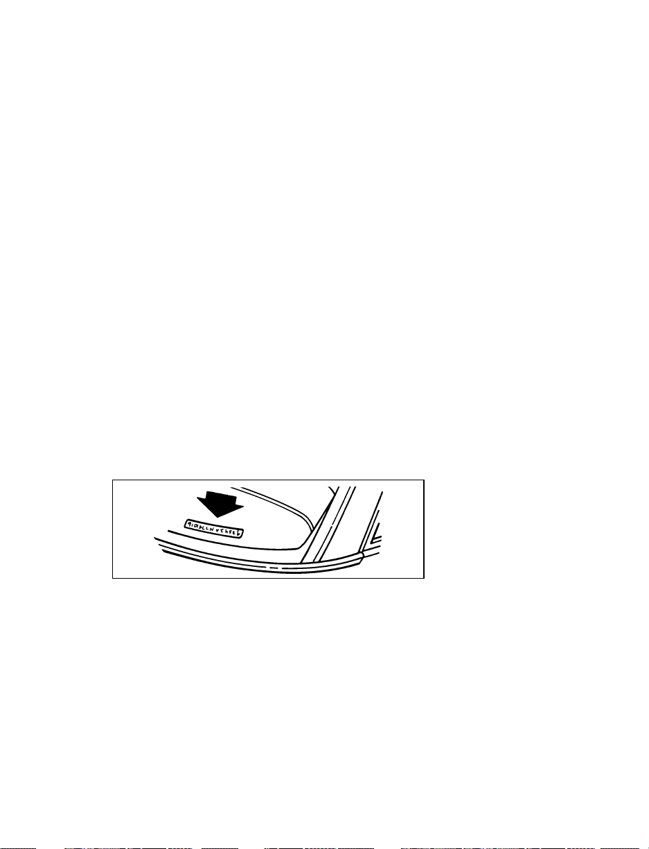
The Vehicle Identification Number is attached to
your vehicle in the following places:
Complete Ford Built Vehicles
on the metal tag attached to the top of the
❑
instrument panel on the driver’s side — you
can see the tag by looking through the
windshield from outside your vehicle.
Vehicle Identification Number (VIN/Serial Number)
on the Safety Compliance Certification Label
❑
— this label is attached to the left front door
lock facing or the door latch post pillar. It is
required by the National Highway Traffic
Safety Administration and is made of special
material. If someone tampers with it, it will
be destroyed and/or a destruction pattern
will appear.
6
Page 10

The label contains the name of the manufacturer,
the month and year of manufacture, the
certification statement and the Vehicle
Identification Number. The label also contains
Gross Vehicle Weight Rating and Gross Axle
Weight Ratings, wheel and tire data and
information codes for additional vehicle data.
For further information about the Safety
Compliance Certification Label and the
information contained on it, refer to the Index.
Incomplete Vehicles
On completed derivations of incomplete vehicles,
the Safety Compliance Certification Label is
affixed at a location determined by a subsequent
stage manufacturer of the completed vehicle. In
these cases the completed vehicle is
manufactured in two (or more) stages by two (or
more) separate manufacturers, with the
manufacture of the completed vehicle occurring
at a later date than the manufacture of the
incomplete vehicle. Consequently, the model
year of the completed vehicle may be later than
the model year of its chassis.
Federal Highway Administration
Regulation
Regulations such as those issued by the Federal
Highway Administration or issued pursuant to
the Occupational Safety and Health Act (OSHA),
and/or state and local laws and regulations may
require additional equipment for the way you
intend to use the vehicle. It is the responsibility
of the registered owner to determine the
applicability of such laws and regulations to
your intended use for the vehicle, and to
arrange for the installation of required
equipment. Your Ford dealer has information
about the availability of many items of
equipment which may be ordered for your
vehicle.
7
Page 11

Your new vehicle goes through an adjustment or
break-in period during the first 1,000 miles
(1,600 km) that you drive it. During the break-in
period, you need to pay careful attention to how
you drive your vehicle.
Avoid sudden stops. Because your vehicle
❑
has new brake linings, you should take these
steps:
— Watch traffic carefully so that you can
anticipate when to stop.
— Begin braking well in advance.
— Apply the brakes gradually.
The break-in period for new brake linings
lasts for 100 miles (160 km) of city driving or
1,000 miles (1,600 km) of highway driving.
Wheel lug nuts must be retightened to proper
❑
torque specifications at 500 miles/800 km of
new vehicle operation. Proper torque
specifications are provided in this guide. Also
retighten to proper torque specification at 500
miles/800 km after any wheel change or any
other time the wheel lug nuts have been
loosened.
Use only the type of engine oil that Ford
❑
recommends. See Engine oil recommendations
in the Index. Do not use special “break-in”
oils.
8
Page 12

Vehicle
Washing and Polishing Your Vehicle
Wash the outside of your vehicle, including the
underside, with a mild detergent.
DO NOT:
Wash your vehicle with hot water
❑
Wash your vehicle while it sits in direct
❑
sunlight
Wash your vehicle while the body is hot
❑
Pollen, bird droppings and tree sap can damage
the paint, especially in hot weather. Wash your
vehicle as often as necessary to keep it clean.
Take similar precautions if your vehicle is
exposed to chemical industrial fallout.
Paint damage resulting from fallout is not
related to a defect in paint materials or
workmanship and therefore is not covered by
warranty. Ford, however, believes that continual
improvement in customer satisfaction is a high
priority. For this reason, Ford has authorized its
dealers to repair, at no charge to the owner, the
surfaces of new vehicles damaged by
environmental fallout within 12 months or 12,000
miles (20,000 km) of purchase, whichever comes
first. Customers may be required to bring their
vehicle in for inspection by a Ford
representative.
Polish your vehicle to remove harmful deposits
and protect the finish.
9
Page 13

Cleaning Chrome and Aluminum Parts
Wash chrome and aluminum parts with the
same detergent you use to wash the vehicle
body, such as Ford Premium Car Wash
Concentrate. You can use Ford Extra Strength
Tar and Road Oil Remover or equivalent to
clean grease, oil, and tar from chrome-plated
parts, including wheelcovers, aluminum wheels,
bumpers, or anodized aluminum parts.
Cleaning Plastic Parts
Some of your vehicle’s exterior trim parts are
plastic. Clean with a tar and road oil remover if
necessary. Use a vinyl cleaner for routine
cleaning.
Do not clean plastic parts with thinners, solvents
or petroleum-based cleaners.
If you have your vehicle rustproofed, remove
oversprayed rustproofing with a tar and road oil
remover. If rustproofing is not removed from
plastic and rubber parts, it can cause
deterioration.
10
Page 14

Safety Restraints
The use of safety belts helps to restrain you and
your passengers in case of a collision. In most
states and in Canada the law requires their use.
Safety belts provide best restraint when:
the seatback is upright
❑
the occupant is sitting upright (not slouched)
❑
the lap belt is snug and low on the hips
❑
the shoulder belt is snug against the chest
❑
the knees are straight forward
❑
To help you remember to fasten your safety belt,
a warning light may come on and a chime may
sound. See Safety Belt Warning Light and Chime in
the Warning Lights and Gauges chapter.
See the following sections in this chapter for
directions on how to properly use these safety
belts. Also see Safety Restraints for Children in this
chapter for special instructions about using
safety belts for children.
RWARNING
Make sure that you and your passengers
wear safety belts. Always drive and ride
with your seatback upright and the lap
belt snug and low across the hips.
11
Page 15
RWARNING
Passengers should not be allowed to ride
in the cargo area. Persons not riding in a
seat with a fastened seat belt are much
more likely to suffer serious injury in a
collision. Cargo should always be secured
to prevent it from shifting and causing
damage to the vehicle or harm to
passengers.
RWARNING
Never let a passenger hold a child on his
or her lap while the vehicle is moving.
The passenger cannot protect the child
from injury in a collision.
RWARNING
To reduce the risk of serious injury in a
collision, children should always ride with
the seatback upright.
RWARNING
Never wear the shoulder belt under the
arm. Never swing it around the neck over
the inside shoulder. Never use a single
belt for more than one person or across
more than one seating position. Each
seating position in your vehicle has a
specific safety belt assembly which is
made up of one buckle and one tongue
that are designed to be used as a pair.
Failure to follow these precautions could
increase the risk and/or severity of injury
in a collision.
12
Page 16

RWARNING
Lock the doors of your vehicle before
driving to lessen the risk of the door
coming open in a collision.
Your vehicle is equipped with a dual locking
mode retractor on the shoulder belt portion of
the combination lap/shoulder safety belt for
front seat passenger and rear seat outboard
passengers.
Dual Locking Mode Retractors
Vehicle Sensitive (Emergency) Locking Mode
In this operating mode, the shoulder belt
retractor will allow the occupant freedom of
movement, locking tight only on hard braking,
hard cornering or impacts of approximately
5 mph (8 km/h) or more.
The front seat belt retractor can also be made to
lock by pulling/jerking on the belt.
Automatic Locking Mode
In this operating mode, the shoulder belt
retractor will be automatically locked and remain
locked when the combination lap/shoulder
safety belt is buckled, and does not allow the
occupant freedom of movement. This mode
provides the following:
A tight lap/shoulder belt fit on occupant
❑
Child seat/infant carrier installation restraint
❑
This mode must be used when installing a child
seat on the front passenger seat and rear
outboard seats where dual locking retractors are
provided.
13
Page 17

To switch the retractor from the “emergency
locking mode” to the “automatic locking mode,”
perform the following steps:
1. Buckle the lap/shoulder combination belt.
2. Grasp the shoulder portion of the belt and
pull downward until all of the belt is
extracted, and when allowed to retract, a
clicking sound will be heard. At this time,
the belt retractor is in the “automatic locking
mode” (child restraint mode).
3. A clicking sound will continue to be heard
as the belt is allowed to retract. This
indicates that the retractor is in the
“automatic locking mode.”
NOTE: When the combination lap/shoulder
belt is unbuckled and allowed to
retract completely, the retractor will
switch back to the vehicle sensitive
(emergency) locking mode. See the
detailed instructions under Safety Seats
for Children in this chapter.
Belts
While your vehicle is in motion, the combination
lap and shoulder belt adjusts to your movement.
However, if you brake hard, corner hard or if
your truck receives an impact of 5 mph
(8 km/h) or more, the combination lap/shoulder
belt locks and helps reduce your forward
movement. The front seat belt systems can also
be made to lock by jerking on the shoulder belt.
NOTE: The rear belts cannot be made to lock
up by jerking on shoulder belt.
14
Page 18
After you get into your vehicle, close the door
and lock it. Then adjust the seat to the position
that suits you best.
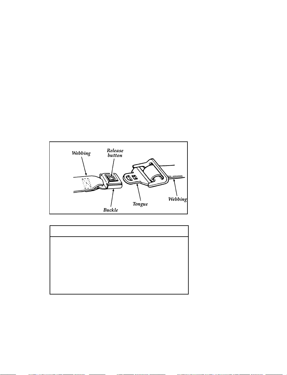
To fasten the belt
Pull the combination lap/shoulder belt from the
retractor so that the shoulder portion of the belt
crosses your shoulder and chest. Be sure the belt
is not twisted. If it is, remove the twist. Insert
the belt tongue into the proper buckle until you
hear a snap and feel it latch. Make sure the
tongue is securely fastened to the buckle by
pulling on tongue.
RWARNING
Use the shoulder belt on the outside
shoulder only. Never wear the shoulder
belt under the arm. Never swing it around
the neck over the inside shoulder. Never
use a single belt for more than one
person. Failure to follow these precautions
could increase the risk and/or severity of
injury in a collision.
To tighten the lap portion of the belt, pull up on
the shoulder belt until it fits you snugly. The
belt should rest as low on your hips as possible.
15
Page 19

RWARNING
Front and rear seat occupants, including
pregnant women, should wear safety belts
for optimum protection in an accident.
Due to folding rear seats, sometimes the buckles
and tongues toward the center of the vehicle
may be hidden by the rear edge of the seat
cushion. Pull them out so they will be accessible.
While you are fastened in the seat belt, the
combination lap and shoulder belt adjusts to
your movement. However, if you brake hard,
turn hard, or if your vehicle receives an impact
of 5 mph (8 km/h) or more, the lap and
shoulder belt will become locked and help
reduce your forward movement.
All Three Passenger Bench/Bed Seat or
Captain’s Chair
In addition to anchorages in the floor and roof
structures, some rear safety belts have a
detachable anchor mounted to the outboard side
of the rear seats. This should remain attached,
except when removing the rear seats.
The second row passenger side outboard seating
position uses a hook above the sliding/cargo
door to stow the shoulder safety belt when
entering or exiting the vehicle or when it is not
being used.
NOTE: When the belt is stowed using the
hook, DO NOT use the hanging belt as
an assist when entering the vehicle.
16
Page 20
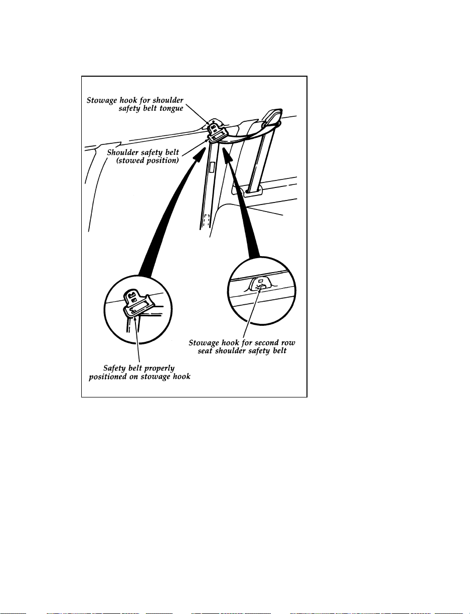
Proper stowage of shoulder safety belt
17
Page 21
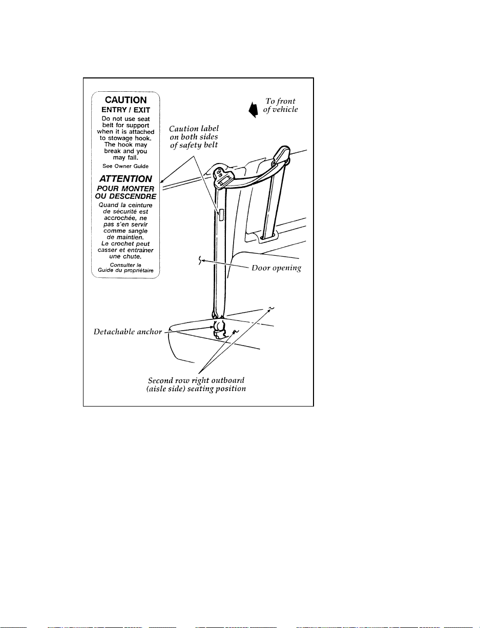
Location of the stowage hook caution label on safety belt
18
Page 22
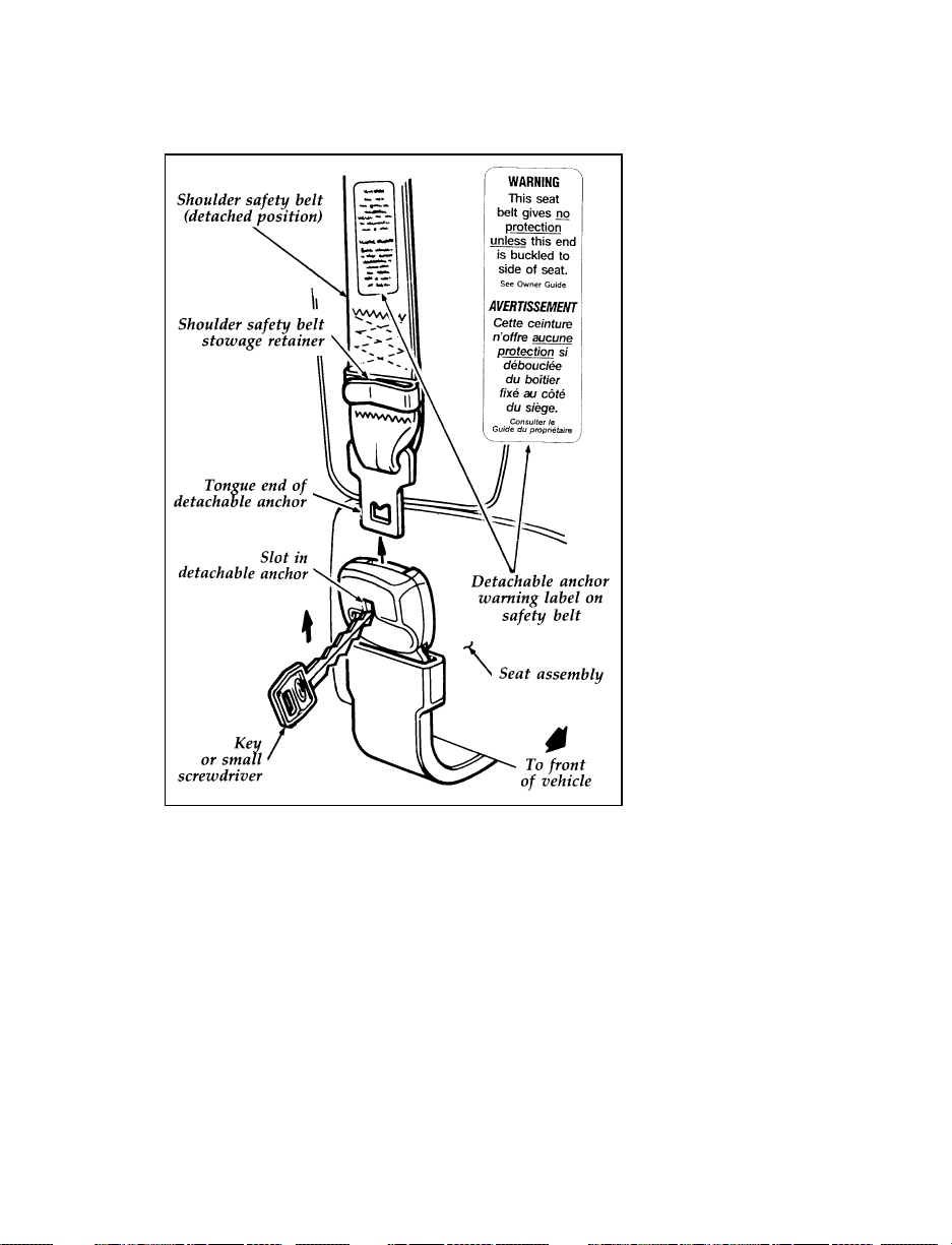
Location of the detachable anchor warning label on safety
belt
In order to remove the rear seat, the safety belt
must be disengaged from the seat. To disengage
the safety belt from the seat, insert a key or
small screwdriver into the slot provided on the
detachable anchor. Then lift upward. See
previous illustration.
19
Page 23
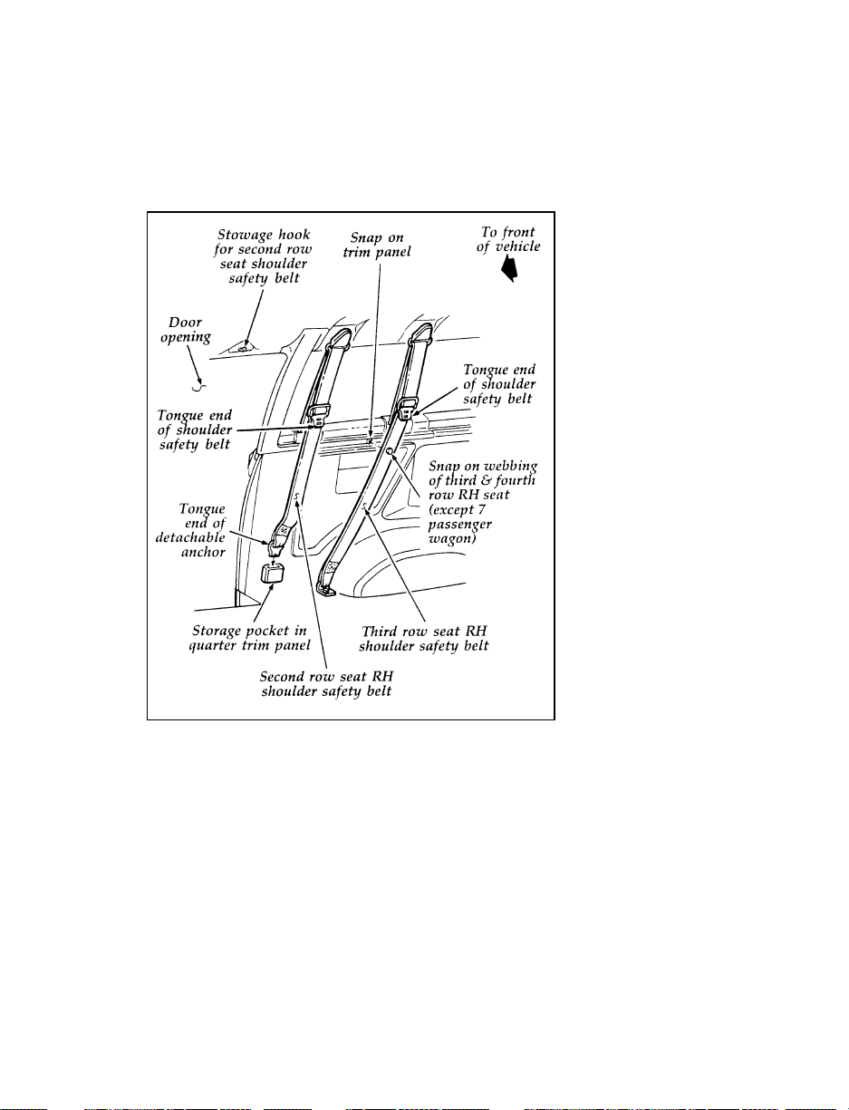
Whenever a rear seat has been removed, the
tongue end of the detachable anchor must be
correctly stowed. See the following illustrations.
Rear seat shoulder safety belt — stowage (with seat
removed)
20
Page 24
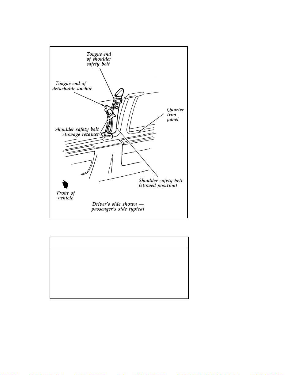
Rear seat shoulder safety belt — stowage (with seat
removed)
RWARNING
When reinstalling a rear seat in your
vehicle it must be placed in its original
position. Improper installation of the seat
will prevent correct use of the safety belts
and could increase the risk of injury.
Refer to the warning label on the seat
belt.
21
Page 25
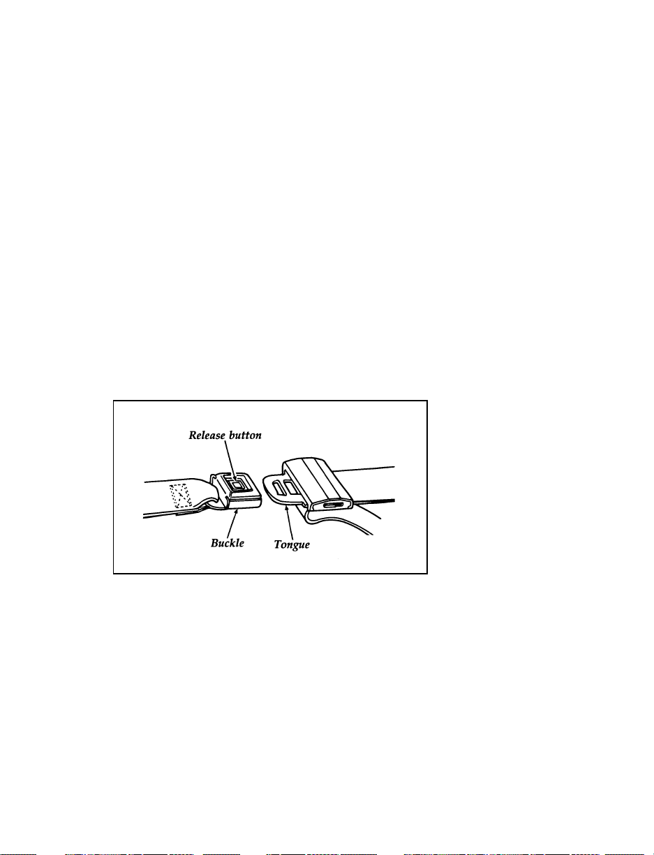
After installing the rear seat, make sure the
safety belt is not twisted before you insert it into
the detachable anchor. A twisted safety belt may
cause the retractor to not work properly. Then
insert the detachable anchor tongue into the
detachable anchor until you hear a “snap” and
feel the latch engage.
Adjustable Lap Belts Without Retractors
On the center seat of the three-passenger bench
seat, and both inboard seats of the
four-passenger bench seat, you will find a lap
belt without a retractor, but does have a locking
adjustable tongue. Shorten and fasten these belts
when you are not using them. To make each
belt longer, tip the tongue at a right angle to the
belt and pull the belt over your lap until the
tongue reaches the buckle.
Fastening occupant safety lap belts
To fasten the belt, pull the belt across your hips
and insert the tongue into the correct buckle on
your seat until you hear a snap and feel it latch.
Make sure the buckle is securely fastened by
pulling tongue.
22
Page 26
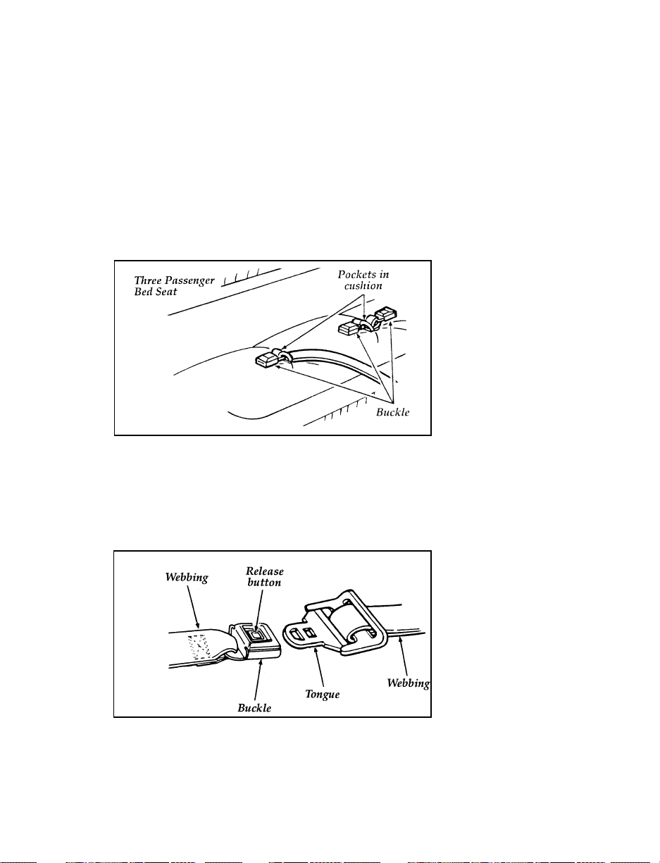
Adjust the belt so that it fits snugly and as low
as possible around the hips:
If you need to lengthen the belt, unfasten it
❑
and repeat the procedure above.
If you need to shorten the belt, pull on the
❑
loose end of the webbing.
Safety Belt Bed/Seat Pocket
Location of the safety belt bed/seat pockets
To unfasten the belt:
1. Push the release button on the buckle. This
allows the tongue to unlatch from the
buckle.
Unfastening the outboard lap/shoulder belts
23
Page 27

2. While the belt retracts, guide the tongue to
its stowed position. If you do not guide the
tongue, it may strike you or part of the
vehicle.
How to Untwist or Unjam a Safety Belt
Retractor
If you should jam the lap belt retractor by
allowing the belt to retract when it is twisted,
you can free the webbing with this procedure:
1. Pull on the belt with both hands to tighten it
on the retractor spool.
2. Feed the belt back into the retractor until it
is completely retracted. Repeat previous step
if necessary.
3. Pull the belt out of the retractor as far as it
will go and untwist the belt or remove the
object that is jamming the belt. Let the belt
retract.
4. Then, pull the belt out and let it retract
several times to make sure that the belt
works properly.
24
Page 28
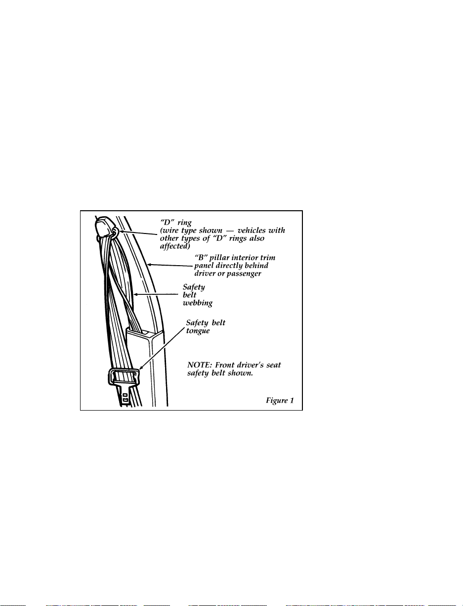
Procedure to Correct a Twisted Safety
Shoulder Belt at the “D” Ring (if so
equipped) Front and/or Rear Outboard
Seating Positions.
NOTE: The restraint system shown in the
following figures may be different than
the restraint system in your vehicle.
However, use these figures and this
procedure to correct a twisted safety
shoulder belt at any outboard seating
position that has a “D” ring.
25
Page 29
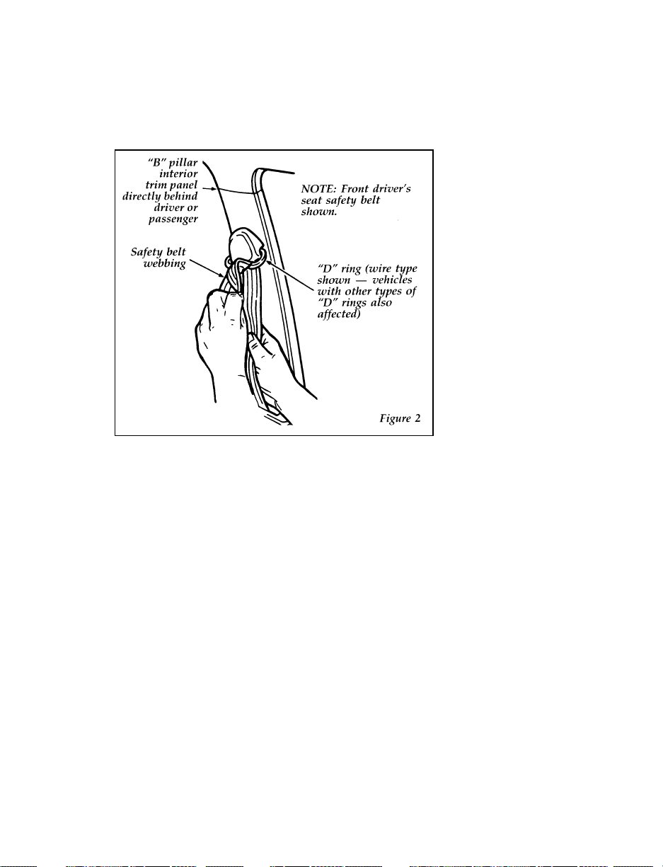
1. Grasp the belt webbing at the “D” ring. See
Figure 2.
2. Rotate and fold the belt webbing over itself
as required to remove the twist.
3. Feed the folded portion of the belt through
the “D” ring.
26
Page 30

4. When completed, the safety belt should look
like Figure 3.
Safety Belt Extension Assembly
For some people, the safety belt may be too
short even when it is fully extended. You can
add about eight inches (20 cm) to the belt length
with a safety belt extension assembly (part
number 611C22). Safety belt extensions are
available at no cost from your dealer.
Use only extensions manufactured by the same
supplier as the safety belt. Manufacturer
identification is located at the end of the
webbing on the label. Also, use the safety belt
extension only if the safety belt is too short for
you when fully extended. Do not use extension
to change the fit of the shoulder belt across the
torso.
27
Page 31

RWARNING
Failure to follow these instructions will
affect the performance of the safety belts
and increase the risk of personal injury.
Check your safety belt system periodically to
make sure that it works properly and isn’t
damaged. If the webbing shows any wear, nicks
or cuts, have it examined by a qualified
technician to determine if replacement is
necessary. Always have your safety belt system
checked after a collision by a qualified
technician.
All safety belt assemblies, including retractors,
buckles, front seat belt buckle support assemblies
(slide bar) (if so equipped), child safety seat
tether bracket assemblies (if so equipped), and
attaching hardware, should be inspected after
any collision. Ford recommends that all safety
belt assemblies used in vehicles involved in a
collision be replaced. However, if the collision
was minor and a qualified technician finds that
the belts do not show damage and continue to
operate properly, they do not need to be
replaced. Safety belt assemblies not in use
during a collision should also be inspected and
replaced if either damage or improper operation
is noted.
Cleaning the Safety Belts
Clean the safety belts with any mild soap
solution that is recommended for cleaning
upholstery or carpets. Do not bleach or dye the
belt webbing because this may weaken it.
28
Page 32

System (SRS)
Driver air bag for E-150, E-250 and E-350,
except cutaway and strip chassis
If the letters “SRS” appear in the center of the
steering wheel, your vehicle is equipped with a
driver side air bag supplemental restraint
system, located in the steering wheel.
The driver air bag is a Supplemental Restraint
System (SRS), provided in addition to the driver
lap/shoulder belt, and is designed to
supplement the protection provided to a
properly belted driver in moderate to severe
frontal collisions. The supplemental air bag
system does not provide restraint to the lower
body.
The Importance of Wearing Safety Belts
RWARNING
Safety belts must be worn by all vehicle
occupants to be properly restrained and
help reduce the risk of injury in a
collision.
RWARNING
All occupants of the vehicle, including the
driver, should always wear their safety
belts, even when an air bag Supplemental
Restraint System is provided.
29
Page 33

There are four very important reasons to use
safety belts even with an air bag system. Use
your safety belts to:
help keep you in the proper seating position
❑
(away from the air bag) when it inflates
reduce the risk of harm in rollover, side or
❑
rear impact collisions, because an air bag is
not designed to inflate in such situations
reduce the risk of harm in frontal collisions
❑
that are not severe enough to activate the
supplemental air bag
reduce the risk of being thrown from your
❑
vehicle
The Importance of Being Properly Seated
In a collision, the air bag must inflate extremely
fast to help provide additional protection for
you. In order to do this, the air bag must inflate
with considerable force. If you are not seated in
a normal riding position with your back against
the seatback, the air bag may not protect you
properly and could possibly hurt you as it
inflates.
RWARNING
Do not place objects or mount equipment
on or near the air bag cover on the
steering wheel or in front seat areas that
may come in contact with a deploying air
bag. Failure to follow this instruction may
increase the risk of personal injury in the
event of a collision.
30
Page 34
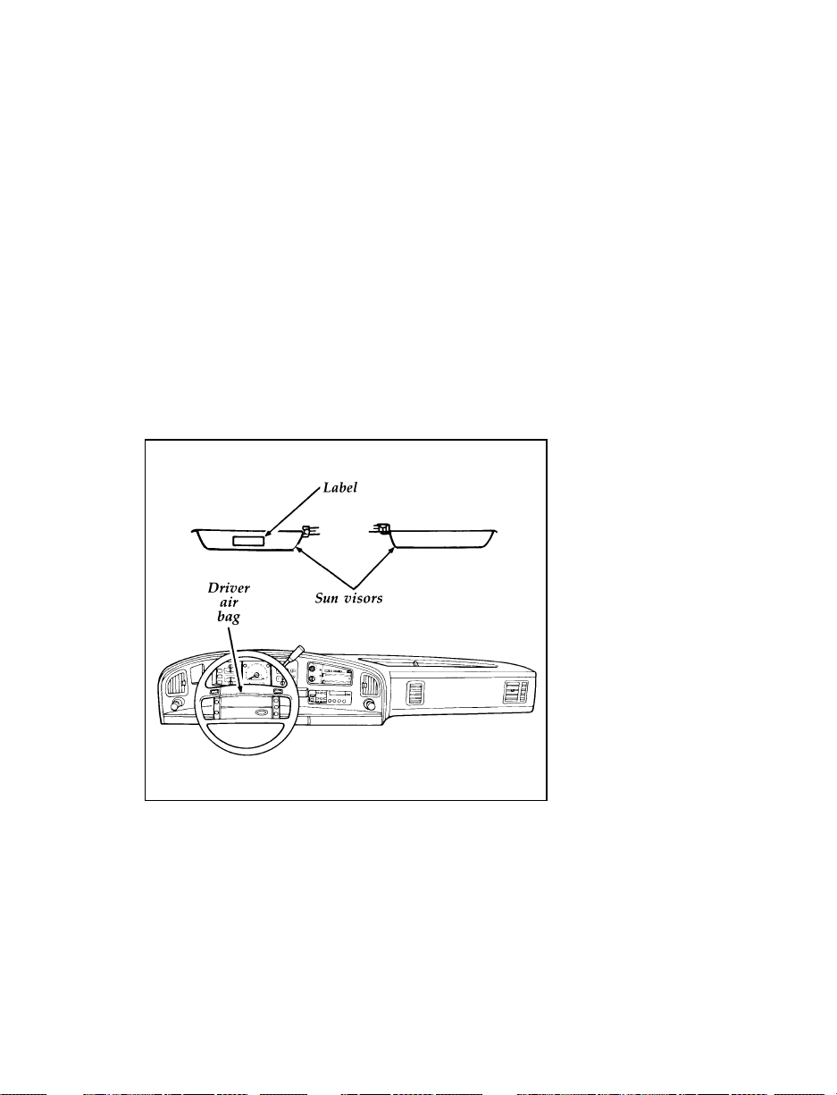
How the Air Bag Supplemental Restraint
System Operates
The air bag supplemental restraint system has
two main parts. One part is the air bag system
with the driver air bag and inflator located in
the center of the steering wheel. The second part
is the electrical system, which has impact
sensors, and a diagnostic module, and backup
power supply. The diagnostic module monitors
its own internal circuits and the supplemental air
bag electrical system readiness, including the
impact sensors, the system wiring, the air bag
system readiness light, air bag power, and the
air bag ignitor.
The location of the air bag and warning label
31
Page 35

The air bag system uses a readiness light on the
instrument cluster or a tone to indicate the
condition of the system. When you turn the
ignition to the ON position, this light will
illuminate for approximately six (6) seconds and
then turn off. This indicates that the system is
operating normally. NOTE: Maintenance of the
air bag system is not required.
A problem with the system is indicated by one
or more of the following: the readiness light will
either flash or stay lit, or it will not light, or a
group of five beeps will be heard.
RWARNING
If any of these things happen, even
intermittently, have the air bag system
serviced at your Ford or Lincoln-Mercury
dealer immediately.
Tone generator
The air bag readiness light indicates the air bag
system condition. However, a series of five sets
of five beeps will be heard only if the readiness
light does not work and there is a problem with
the air bag system. This also means that the Air
Bag Supplemental Restraint System (SRS) is in
need of service. The tone pattern will repeat
(five sets of five beeps) periodically until the
problem and light are repaired. Unless serviced,
the Air Bag Supplemental Restraint System may
not function properly in the event of a collision.
RWARNING
Do not attempt to service, repair, or
modify the Air Bag Supplemental
Restraint System or its fuses. See your
Ford or Lincoln-Mercury dealer.
32
Page 36

The air bag system is designed to stay out of
sight until it is activated. The air bag system is
designed to deploy in frontal and front-angled
collisions more severe than hitting a parked
vehicle of similar size and weight head-on at
about 28 mph (45 km/h). Because the system
senses the crash severity rather than vehicle
speed, some frontal collisions at speeds above
28 mph (45 km/h) will not inflate the air bag.
The system activates when the sensors detect a
forward deceleration equal to or greater than the
deceleration experienced if you would drive
your vehicle into a solid wall at 14 mph. In
some side impacts, the forward deceleration of
your vehicle can be great enough to deploy your
air bag.
The following four steps show how the air bag
system works:
1. Sensors in the vehicle will detect the degree
of severity of a frontal impact. When the
sensor system is activated, electric current
flows to the inflator and the system ignites
the gas generant.
2. The propellant then rapidly burns in the
metal container. The rapid burning produces
nitrogen gas and small amounts of dust. The
nitrogen gas and dust are cooled and filtered
during inflation of the air bag.
3. The inflating supplemental air bag splits
open the trim cover. The supplemental air
bag then rapidly unfolds and inflates in front
of the driver.
NOTE: STEPS 1-3 TAKE PLACE IN A
FRACTION OF A SECOND.
4. After inflation, the gas empties through holes
in the air bag. The air bag deflates at once.
33
Page 37

The surface of the air bags and the vehicle
interior may be dusted with a powdery residue.
The powder is cornstarch or talcum powder,
which is used to lubricate the air bag as it
inflates, and sodium compounds such as sodium
carbonates (e.g., baking soda), and possibly a
very small amount of sodium hydroxide that
may be irritating to the skin and eyes, but is not
toxic.
Right after air bag inflation, you may notice
smoke (from the powder and dust) and smell
the burnt propellant. This is normal.
RWARNING
Air bag system components get hot after
inflation. Do not touch them after
inflation.
Air bags may not inflate in certain frontal
collisions, even though the vehicle may be badly
damaged. The fact that your air bag did not
inflate in such a collision does not mean that
something is wrong with the air bag system.
Rather, it means the crash forces were not severe
enough to need an air bag to prevent serious
injury.
34
Page 38
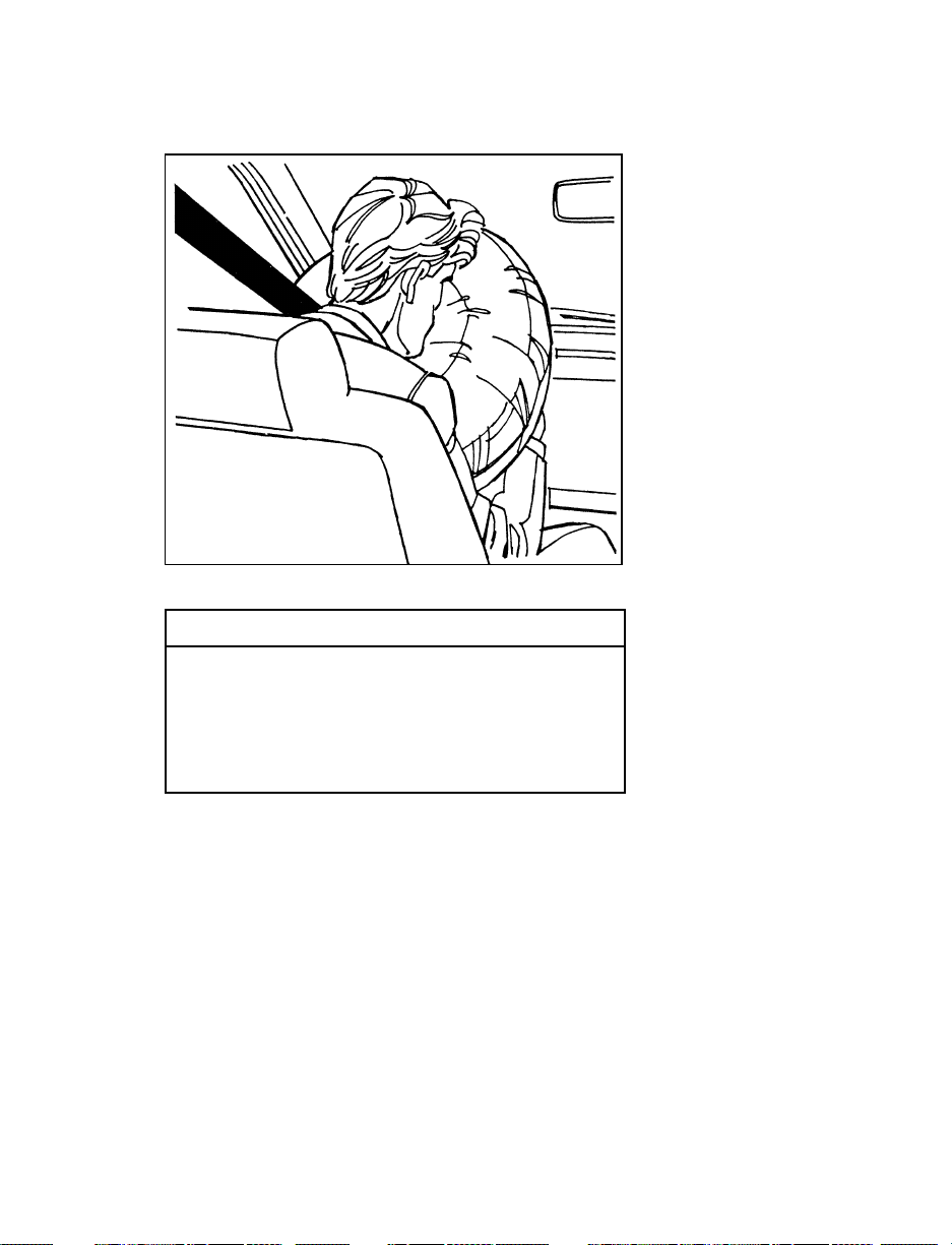
Inflated driver side air bag
RWARNING
If the air bag is inflated, THE AIR BAG
WILL NOT FUNCTION AGAIN AND
MUST BE REPLACED IMMEDIATELY. If
the air bag is not replaced, the unrepaired
area will increase the risk of injury in a
collision.
35
Page 39

Disposal of supplemental air bag equipped
vehicles
For disposal of air bags or air bag equipped
vehicles, see your local Ford or Lincoln-Mercury
dealer, or refer to the procedures in the 1995
Ford Service Manual. Information on how to
order a service manual is available at an
authorized Ford or Lincoln-Mercury dealer. You
can also order a service manual using the order
form in the Accessories chapter of your Owner
Guide.
Service and information labels
Service and information labels are attached to
the sun visors, the headliner above the sun
visors (Canadian vehicles), and the radiator
support in the engine compartment.
36
Page 40
37
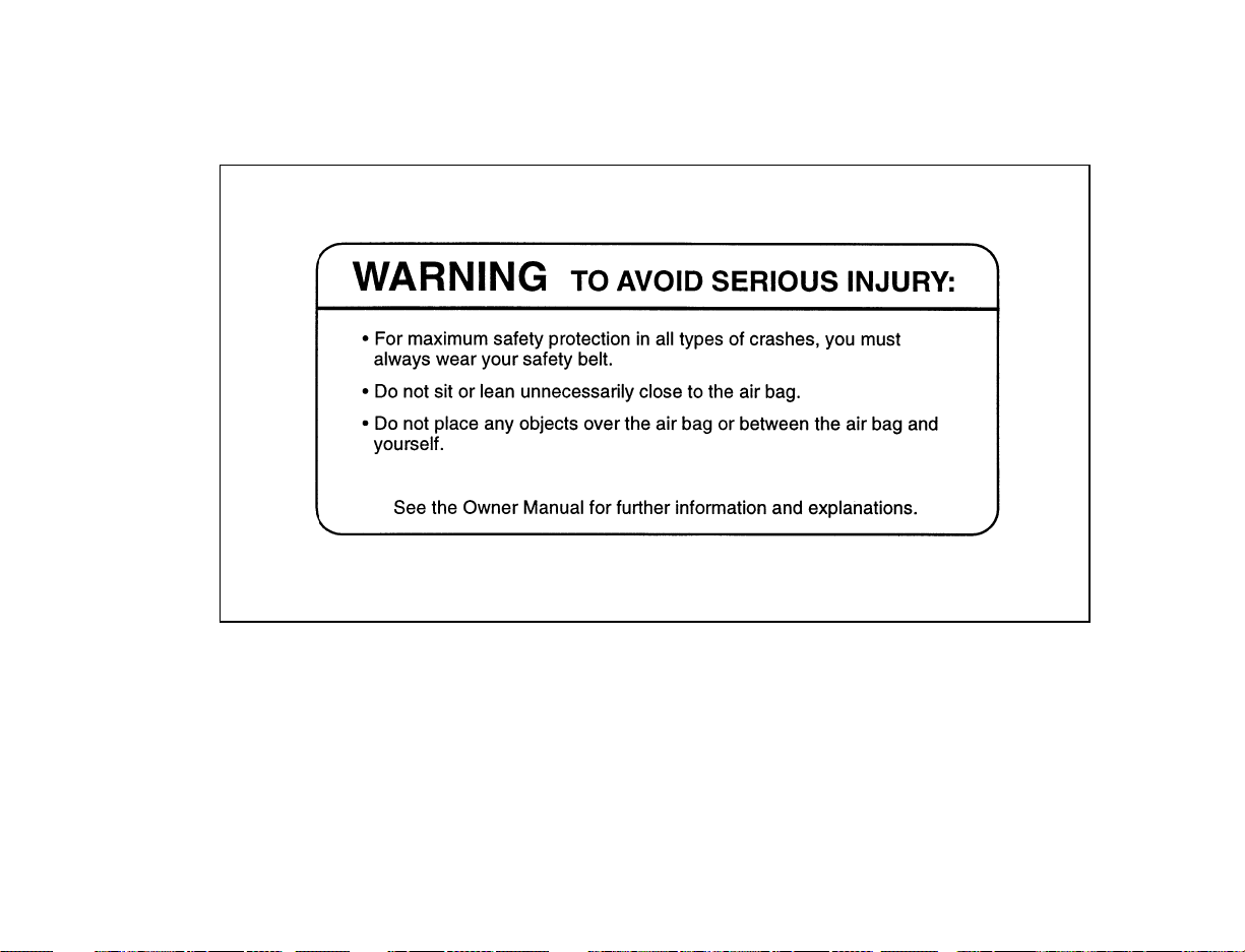
The label located on the back of the driver’s sun visor
Page 41
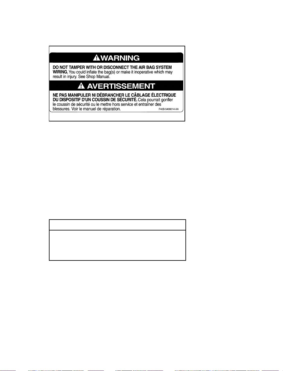
Label on radiator support in the engine compartment
In the U.S. and Canada, you are required by law
to use safety restraints for children. If small
children ride in your vehicle — this generally
includes children who are four years old or
younger and who weigh 40 pounds (18 kg) or
less — you must put them in safety seats that
are made specially for children. Safety belts
alone do not provide maximum protection for
these children. Check your local and state laws
for specific requirements.
RWARNING
Never let a passenger hold a child on his
or her lap while the vehicle is moving.
The passenger cannot protect the child
from injury in a collision.
38
Page 42

RWARNING
Passengers should not be allowed to ride
in the cargo area. Persons not riding in a
seat with a fastened seat belt are much
more likely to suffer serious injury in a
collision. Cargo should always be secured
to prevent it from shifting and causing
damage to the vehicle or harm to
passengers.
RWARNING
Carefully follow all of the manufacturer’s
instructions included with the safety seat
you put in your vehicle. If you do not
install and use the safety seat properly,
the child may be injured in a sudden stop
or collision.
When possible, put children in the rear seat of
your vehicle. Accident statistics suggest that
children are safer when properly restrained in
the rear seating positions than in the front
seating positions.
RWARNING
Safety belts and seats can become hot in a
vehicle that has been closed up in sunny
weather; they could burn a small child.
Check seat covers and buckles before you
place a child anywhere near them.
RWARNING
Never leave a child unattended in your
vehicle.
39
Page 43

Safety Belts for Children
Children who are too large for child safety seats
should always wear safety belts. (See instructions
with your child seat, or contact its manufacturer,
to determine maximum size of child that will
safely fit in the seat.)
RWARNING
If safety belts are not properly worn and
adjusted as described, the risk of serious
injury to the child in a collision will be
much greater.
If the shoulder belt portion of one of the lap and
shoulder belts can be positioned so that it does
not cross or rest in front of the child’s face or
neck, the child should wear the lap and shoulder
belt. Moving the child closer to the center of the
vehicle may help provide a good shoulder belt
fit.
RWARNING
If the shoulder belt cannot be properly
positioned, move the child to one of the
seats with a lap belt only (preferably in a
rear seat) and use the lap belt.
Lap belts and the lap belt portion of lap and
shoulder belts should always be worn snugly
and below the hips, touching the child’s thighs.
RWARNING
To reduce the risk of serious injury in a
collision, children should always ride with
the seatback upright.
40
Page 44

Safety Seats for Children
Use a safety seat that is recommended for the
size and weight of the child. Always follow the
safety seat manufacturer’s instructions when
installing and using the safety seat.
Ford recommends the use of a child safety seat
having a top tether strap. Install the child safety
seat in a seating position which is capable of
providing a tether anchorage. For more
information on top tether straps see Attaching
Safety Seats With Tether Straps in this chapter.
When installing a child safety seat, be sure to
use the correct safety belt buckle for that seating
position making sure the tongue is securely
fastened in the buckle and for a shoulder/lap
belt combination with a sliding tongue make
sure the retractor is in the “automatic locking
mode.”
Most child safety seats can be used in this
vehicle only in vehicle seating positions with
lap-shoulder belts. The Ford Tot-Guard should
NOT be used in this vehicle. Any booster-type
seat that places the vehicle’s lap belt or shoulder
belt around a shield above and ahead of the
child’s hips should not be used in this vehiicle.
This type of safety seat could cause injury by
tipping over the front edge of the vehicle seat
during a collision.
RWARNING
The following instructions MUST BE
FOLLOWED to reduce risk of injury from
a safety seat tipping too far forward in a
severe crash.
41
Page 45

A safety seat can appear to be securely fastened
by the safety belts, but the high forces during a
severe crash could tip it forward if held only by
a lap belt.
Infants (under one year)
Restrain infants in a rear-facing infant safety seat
or convertible safety seat in the rear-facing
position. These safety seats can be placed in any
passenger seating position in this vehicle other
than the last row of a 12 or 15 passenger club
wagon, and restrained by either a lap or
lap-shoulder belt according to the instructions on
the safety seat. In vehicle seats equipped with
lap-shoulder belts make sure the retractor is in
the automatic locking mode.“
Toddlers (one to four years)
Install forward-facing convertible safety seats
only in vehicle seating positions equipped with
lap-shoulder belts. Forward facing convertible
safety seats can be used in the center of the
three-passenger second row bench seat only if a
top tether strap is used. Ford recommends
placing forward-facing safety seats in the second
row and using safety seats with top tether straps
for added protection. For more information on
top tether straps see Attaching safety seats with
tether straps later in this section.
RWARNING
DO NOT use a forward-facing safety seat
or an infant seat in the last row of a 12or 15-passenger Club Wagon.
All child restraint systems are designed to be
secured in vehicle seats by lap belts or by the
lap portion of a lap-shoulder belt.
42
Page 46
RWARNING
If you do not properly secure the safety
seat, the child occupying the seat may be
injured during a collision or sudden stop.
An unsecured safety seat could also injure
other passengers.
RWARNING
Carefully follow all of the manufacturer’s
instructions included with the safety seat
you put in your vehicle. If you do not
install and use the safety seat properly,
the child may be injured in a sudden stop
or collision.
RWARNING
Seatbacks should be upright for use with
child safety seats.
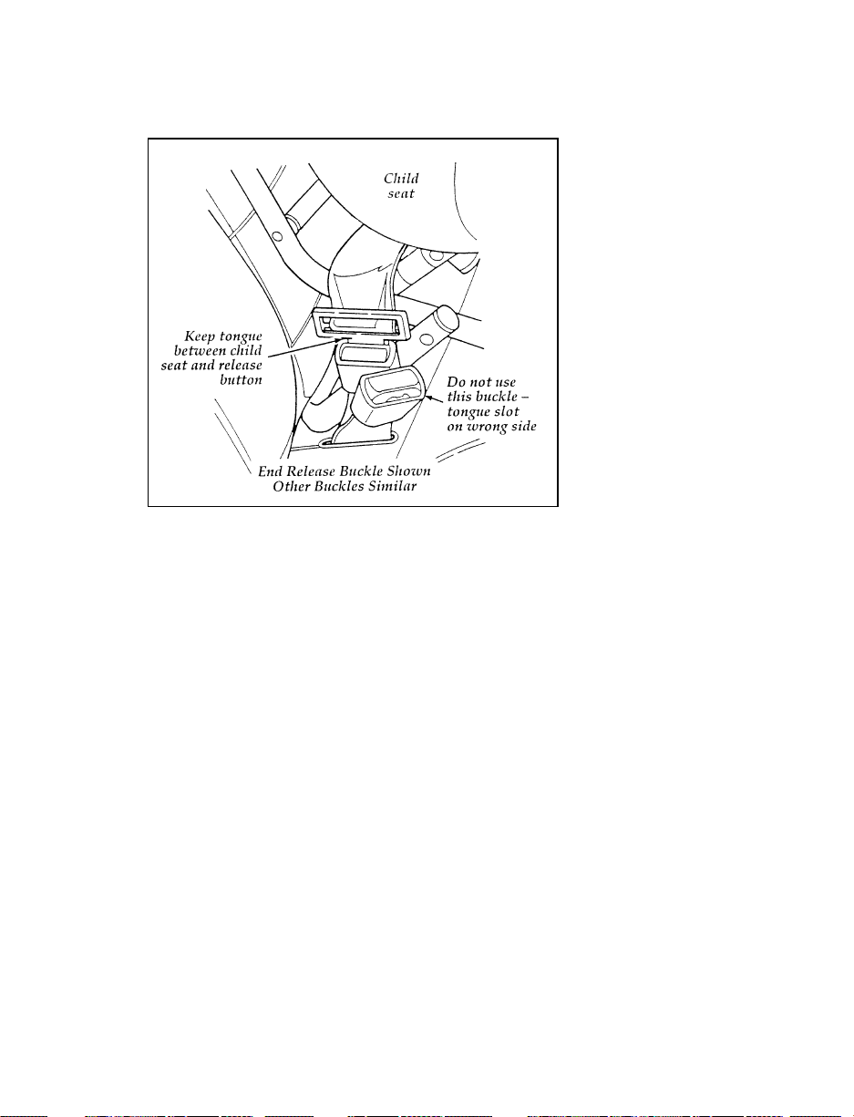
RWARNING
Always keep the buckle release button
pointing upward and away from the child
seat, with the tongue between the child
seat and the release button as shown in
the following illustration.
43
Page 47
Installing Child Safety Seats
Your vehicle is equipped with a dual locking
mode retractor on the shoulder belt portion of
the combination lap/shoulder safety belt for the
front seat passenger and rear seat outboard
passengers.
If you choose to install a forward-facing child
safety seat or infant carrier in the front seating
positions, move vehicle seat as far back as
possible.
For seating positions equipped with a
dual-locking mode retractor, use the following
procedure:
1. Position the child seat in the center of the
passenger seat.
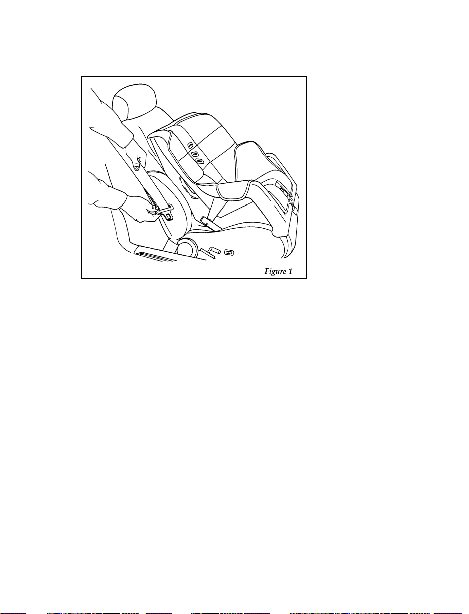
2. Pull down on shoulder belt, then grasp
shoulder belt and lap belt together. Figure 1.
44
Page 48
3. While holding the shoulder and lap belt
portions together, route the tongue through
the child seat according to the child seat
manufacturer’s instructions. See Figure 2. Be
sure that the belt webbing is not twisted.
45
Page 49
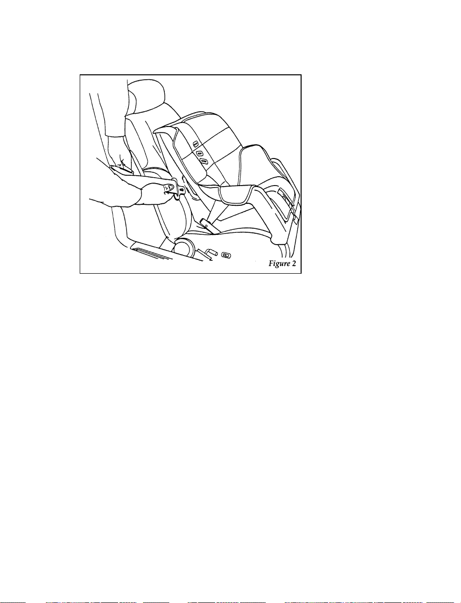
Routing the lap/shoulder belt
4. Insert the belt tongue into the buckle for that
seating position until you hear and feel the
latch engage. Figure 3. Make sure tongue is
latched securely to buckle by pulling on
tongue.
46
Page 50
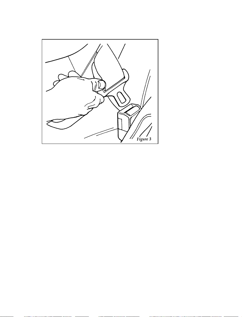
Buckling the belt
5. Grasp the shoulder portion of the belt and
pull downward until all of the belt is
extracted and a click is heard. At this time,
the retractor is in the automatic locking
mode (child seat restraint mode). Figure 4.
NOTE: The dual-locking mode retractor must
be in the automatic locking mode to
properly restrain a child.
47
Page 51
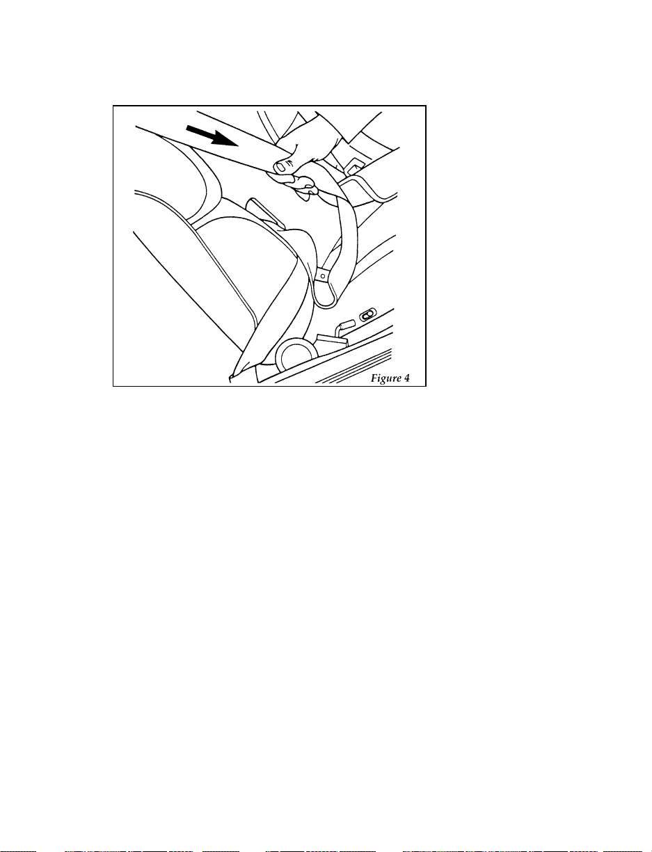
Setting the retractor to automatic locking mode
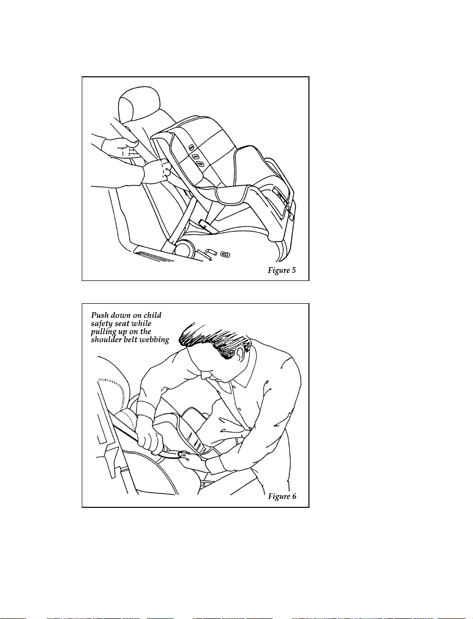
6. Allow the belt to retract. Pull up on the
shoulder webbing. A clicking sound will be
heard as the belt retracts. This indicates the
retractor is in the automatic locking mode.
Push down on the child seat while you pull
up on the belt to remove any slack in the
belt. Figures 5 and 6.
48
Page 52
49
Page 53
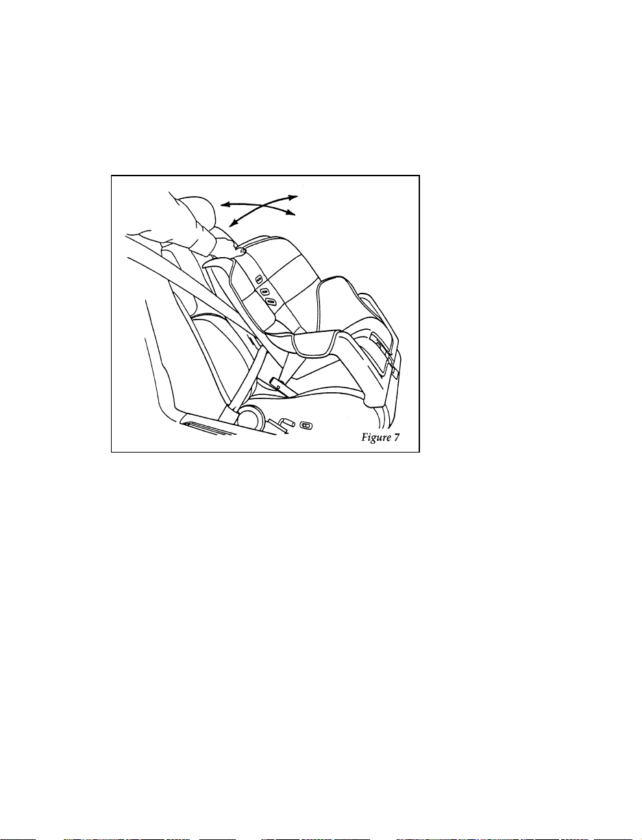
7. Before placing the child in the child seat,
forcibly tilt the seat from side to side, and
tug it forward to make sure that the seat is
securely held in place, Figure 7.
Checking that the seat is secure
50
Page 54
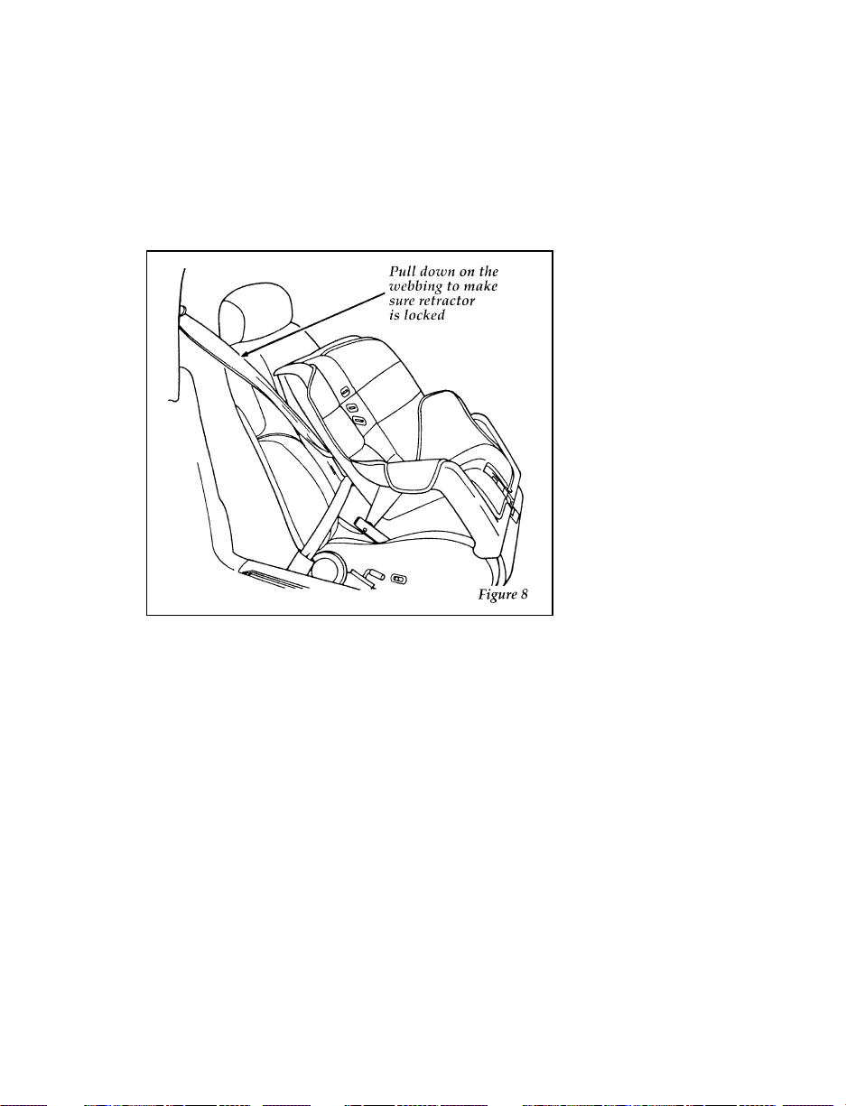
8. Double check that the retractor is in the
automatic locking mode. Try to pull more
belt out of the retractor. If you cannot, the
belt is in the automatic locking mode,
Figure 8.
Checking the retractor
9. Check to make sure that the child seat is
properly secured prior to each use. If the
retractor is not locked, repeat steps 4
through 7.
To remove the retractor from automatic lock
mode, allow webbing to retract fully to its
stowed position and the retractor will
automatically switch back to the vehicle sensitive
locking mode for normal adult usage.
51
Page 55

Installing a Child Safety Seat at the Rear
Center Seating Position with Locking
Adjustable Lap Belt
1. Lengthen the lap belt. To lengthen the belt,
hold the tongue so that its bottom is
perpendicular to the direction of webbing
while sliding the tongue up the webbing.
2. Place the child safety seat in the center
seating position.
3. Route the tongue and webbing through the
child seat according to the child seat
manufacturer’s instructions.
4. Insert the belt tongue into the proper buckle
for the center seating position until you hear
a snap and feel it latch. Make sure the
tongue is securely fastened to the buckle by
pulling on tongue.
5. Push down on the child seat while pulling
on the loose end of the lap belt webbing to
tighten the belt.
6. Before placing the child into child seat,
forcibly tilt the child seat from side-to-side
and in forward directions to ensure that the
seat is held securely in place. If the child
seat moves excessively, repeat steps 5
through 6, or properly install the child seat
in a different seating position.
52
Page 56

Attaching Safety Seats With Tether Straps
General Instructions
Some manufacturers make safety seats that
include an upper tether strap that goes over the
seatback and attaches to an anchoring point.
Other manufacturers offer the tether strap as an
accessory. Contact the manufacturer of your
child safety seat for information about ordering
a tether strap.
You can install a tether strap anchor bracket to
the back of the seat by using a tether anchor kit
(613D74), available at no charge from any Ford
dealer.
Read and follow the instructions provided with
the kit carefully for installation of the child
tether strap anchor.
Follow the child seat manufacturer’s instructions
to attach the tether strap to the tether bracket.
Ford recommends placement of tethered safety
seats in a rear seating position with the tether
strap attached to the tether anchoring point as
shown in the following illustration. The front,
right hand seating position may be used if it is
the only seating position available.
53
Page 57
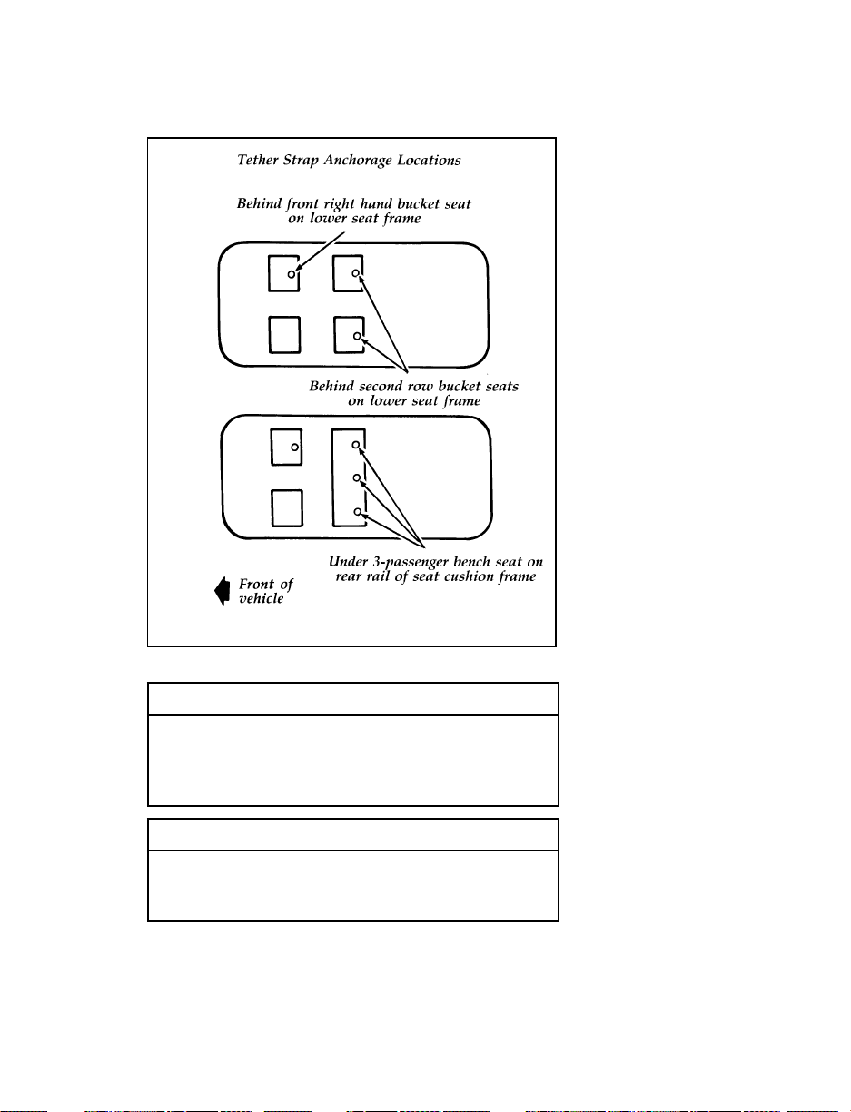
Tether strap anchorage locations
RWARNING
Only use the tether attachment hole
locations shown in the illustrations. The
tether anchor may not perform properly if
the wrong mounting location is used.
RWARNING
Failure to follow these precautions could
increase the chance of injury in an
accident.
54
Page 58
Starting Your Econoline
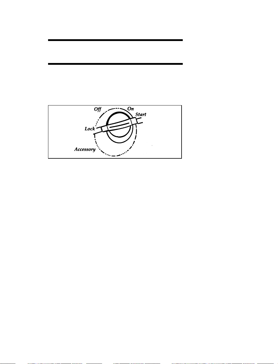
Understanding the Positions of the Ignition
The positions of the key in the ignition lock cylinder.
ON allows you to test your vehicle’s warning
lights (except the brake system warning light) to
make sure they work before you start the
engine. The key returns to the ON position once
the engine is started and remains in this position
while the engine runs.
START cranks the engine. Release the key once
the engine starts so that you do not damage the
starter. The key should return to ON when you
release it. The START position also allows you
to test the brake warning light.
OFF allows you to shut off the engine and all
accessories without locking the steering wheel or
the automatic transmission gearshift lever.
LOCK locks the steering wheel. It also locks the
gearshift.
LOCK is the only position that allows you to
remove the key. The LOCK feature helps to
protect your vehicle from theft.
55
Page 59

If the key is stuck in the LOCK position, move
the steering wheel left or right until the key
turns freely.
ACCESSORY allows some of your vehicle’s
electrical accessories such as the radio and the
windshield wipers to operate while the engine is
not running.
Ignition Key Buzzer or Chime
The buzzer or chime will sound if you open the
driver’s door while the key is in the ignition.
Never leave your vehicle unattended with the
key in the ignition.
Removing the Key From the Ignition
Procedures for removing your key from the
ignition are as follows:
Your vehicle’s gearshift lever is mounted on
the column:
1. Put the gearshift in P (Park).
2. Set the parking brake fully before removing
your foot from the service brake. (This will
avoid “binding” or “loading” the park gear
if you park on a grade.)
3. Turn the ignition key to LOCK.
4. Remove the key.
RWARNING
Always set the parking brake fully and
make sure the gearshift is securely latched
in P (Park).
56
Page 60

RWARNING
Do not leave children, unreliable adults,
or pets alone in your vehicle. They could
accidentally injure themselves or others
through inadvertent operation of the
vehicle. Further, on hot, sunny days,
temperatures in a closed vehicle could
quickly become high enough to cause
severe and possibly fatal injuries to
people as well as animals.
NOTE: For owners of diesel-powered vehicles,
refer to the Diesel Engine Owners Guide
Supplement for information on starting
your vehicle.
When starting a fuel-injected engine, the most
important thing to remember is to avoid
pressing down on the accelerator before or
during starting. Only use the accelerator when
you have problems getting your vehicle started.
See Starting Your Engine in this chapter for
details about when to use the accelerator while
you start your vehicle.
Because your vehicle’s engine is electronically
controlled by a computer, some control
conditions are maintained by power from the
battery. If you ever disconnect the battery, install
a new battery, or experience a dead battery you
must allow the computer to “relearn” its idle
conditions before your vehicle will drive
properly. To let the engine do this, put the
gearshift in P (Park), turn off all the accessories,
and start the vehicle. Let the engine idle for at
least one minute.
57
Page 61

If you do not let the engine relearn its idle, the
idle quality of your vehicle may be adversely
affected until the idle is relearned. Your vehicle
will eventually relearn its idle while you drive
it, but it takes much longer than if you use the
previous procedure.
Starting your vehicle
Preparing to Start Your Vehicle
RWARNING
Do not start your vehicle in a closed
garage or other enclosed area. Never sit in
a stopped vehicle for more than a short
period of time with the engine running.
Exhaust fumes are toxic. See Guarding
Against Exhaust Fumes in this chapter for
more instructions.
Before you start your vehicle, do the following:
1. Make sure you and all your passengers
buckle your safety belts. See Safety Restraints
in the Index for more details.
2. Make sure the headlamps and other
accessories are turned off when starting.
3. Make sure that the gearshift is in P (Park)
and the parking brake is set before you turn
the key.
Testing the Warning Lights
Before you start your vehicle, you should test
the warning lights on the instrument panel to
make sure that they work. Refer to the Warning
Lights and Gauges chapter.
If your Brake Warning Light does light up with
the key in the ON position, you may not have
fully released the parking brake or the brake
fluid may be low.
58
Page 62

Starting Your Engine
To start your engine:
1. Follow the steps under Preparing to Start
Your Vehicle at the beginning of this section.
2. Turn the ignition key to the ON position.
3. DO NOT depress the accelerator pedal when
starting your engine. DO NOT use the
accelerator while the vehicle is parked.
4. Turn the key to the START position
(cranking) until the engine starts. Allow the
key to return to the ON position after the
engine has started.
rotate the steering wheel slightly because it
may be binding.
For a cold engine:
At temperatures 10˚F (-12˚C) and below: If
❑
the engine does not start in fifteen (15)
seconds on the first try, turn the key to OFF,
wait approximately ten (10) seconds so you
do not flood the engine, then try again.
At temperatures above 10˚F (-12˚C): If the
❑
engine does not start in five (5) seconds on
the first try, turn the key to OFF, wait
approximately ten (10) seconds so you do not
flood the engine, then try again.
Do not hold the key in the START position
❑
for more than fifteen (15) seconds at a time.
59
Page 63

For a warm engine:
Do not hold the key in the START position
❑
for more than five (5) seconds at a time. If
the engine does not start within five (5)
seconds on the first try, turn the key to the
OFF position. Wait a few seconds after the
starter stops, then try again.
Whenever you start your vehicle, release the key
as soon as the engine starts. Excessive cranking
could damage the starter or flood the engine.
After you start the engine, let it idle for a few
seconds. Keep your foot on the brake pedal and
put the gearshift lever in gear. Release the
parking brake. Slowly release the brake pedal
and drive away in the normal manner.
NOTE: Your vehicle is equipped with a
brake-shift interlock feature. This
feature prevents you from shifting
from P (Park) unless you have the
brake pedal depressed. (The ignition
must be in the ON position.) If you
cannot shift from P (Park) with the
brake pedal depressed:
1. Apply the parking brake.
2. Remove the key.
3. Insert the key and rotate one position
clockwise (ignition in the OFF position).
4. Apply the brake pedal and shift to N
(Neutral). (If the vehicle is shifted to P
(Park), you must repeat the previous steps.)
5. Start the vehicle.
60
Page 64

If you need to shift out of P (Park) by using the
alternate procedure described above, it is
possible that a fuse has blown and that your
brakelamps may also not be functional. Please
refer to the chapter titled Servicing Your Econoline
in this Owner Guide for instructions on checking
and replacing fuses.
RWARNING
DO NOT DRIVE YOUR VEHICLE UNTIL
YOU VERIFY THAT THE BRAKELAMPS
ARE WORKING.
For cold or warm engines:
If the engine still does not start after two
attempts:
1. Turn the ignition key to the OFF position.
2. Press the accelerator all the way to the floor
and hold it.
3. Turn the ignition key to the START position.
4. Release the ignition key when the engine
starts.
5. Release the accelerator gradually as the
engine speeds up. Then drive away in the
normal manner.
If the engine still does not start, the fuel pump
shut-off switch may have been triggered. For
directions on how to reset the switch see Fuel
Pump Shut-Off Switch later in this chapter.
A computer system controls the engine’s idle
speed. When you start your vehicle, the engine’s
idle speed normally runs higher than when it’s
warmed up. These faster engine speeds will
61
Page 65

make your vehicle move slightly faster than its
normal idle speed. It should, however, slow
down after a short time. If it does not, have the
idle speed checked.
If the engine idle speed does not slow down
automatically, do not allow your vehicle to idle
for more than 10 minutes. Have the vehicle
checked.
RWARNING
Extended idling at high engine speeds can
produce very high temperatures in the
engine and exhaust system, creating the
risk of fire or other damage.
RWARNING
Do not park, idle, or drive your vehicle in
dry grass or other dry ground cover. The
emission system heats up the engine
compartment and exhaust system, which
can start a fire.
If you consistently start your vehicle in subzero
temperatures, use an engine block heater (if
your vehicle has this option).
Engine Block Heater (If equipped)
Engine block heaters are strongly recommended
if you live in a region where temperatures reach
-10˚F (-23˚C) or below. An engine block heater
warms the engine coolant, which improves
starting, warms up the engine faster, and allows
the heater-defrost system to respond quickly.
RWARNING
To prevent electrical shock, do not use
your heater with ungrounded electrical
systems or two-pronged (cheater) adapters.
62
Page 66
For best results, plug the heater in at least three
hours before you start your vehicle. Using the
heater for longer than three hours will not
damage the engine, so you can plug it in at
night to start your vehicle the following
morning.
NOTE: Be sure to disconnect the engine block
heater before driving your vehicle.
Not Start or Does Not Start After
a Collision
Fuel Pump Shut-off Switch
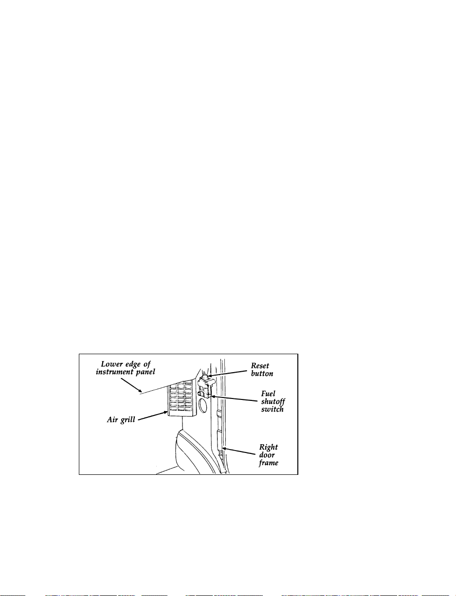
If the engine cranks but does not start or does
not start after a collision, the fuel pump shut-off
switch may have been triggered. The shut-off
switch is a device intended to stop the fuel
pump when your vehicle has been involved in a
substantial jolt.
Once the shut-off switch is triggered, you must
reset the switch by hand before you can start
your vehicle.
Fuel pump shut-off switch location
63
Page 67
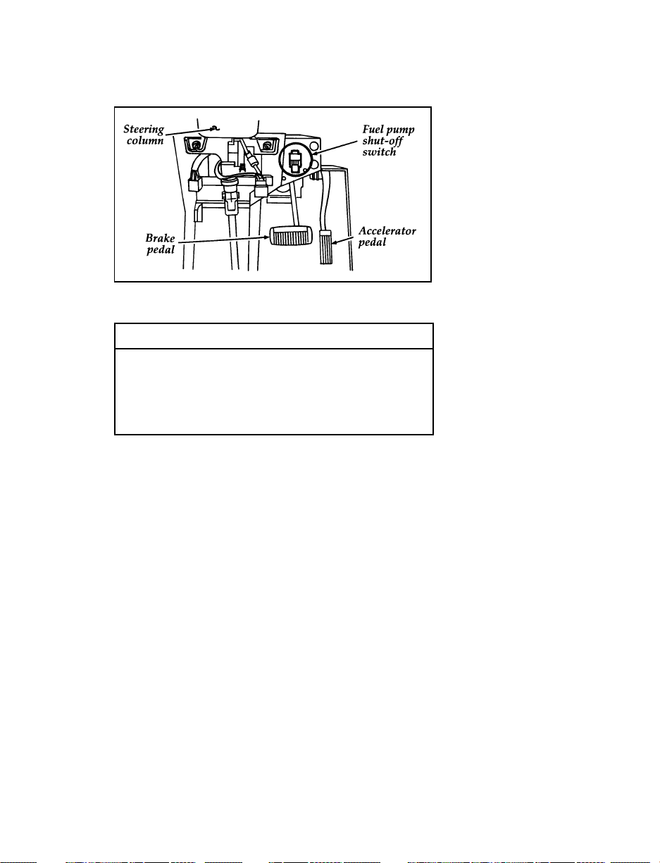
Fuel pump shut-off switch location — Commercial stripped
chassis vehicles
RWARNING
If you see or smell fuel, do not reset the
switch or try to start your vehicle. Have
all the passengers get out of the vehicle
and call the local fire department or a
towing service.
If your engine cranks but does not start after a
collision or substantial jolt:
1. Turn the ignition key to the OFF position.
2. Check under the vehicle for leaking fuel.
3. If you do not see or smell fuel, push the red
reset button down. If the button is already
set, you may have a different mechanical
problem.
4. Turn the ignition key to the ON position for
a few seconds, then turn it to the OFF
position.
5. Check under the vehicle again for leaking
fuel. If you see or smell fuel, do not start
your vehicle again. If you do not see or
smell fuel, you can try to start your vehicle
again.
64
Page 68
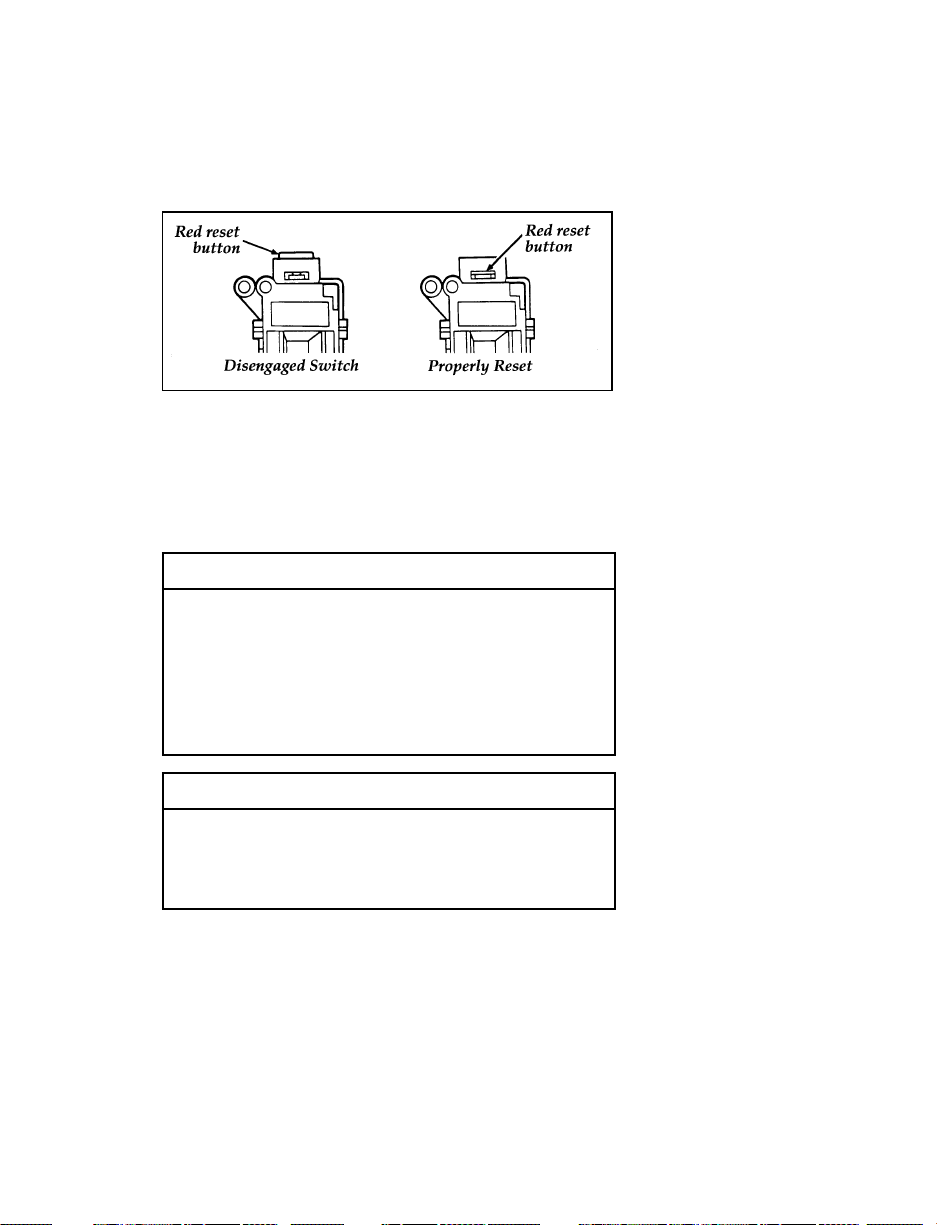
6. Check all vehicle warning lights before
driving your vehicle.
Reset button for fuel pump shut-off switch
Guarding Against Exhaust Fumes
Carbon monoxide, although colorless and
odorless, is present in exhaust fumes. Take
precautions to avoid its dangerous effects.
RWARNING
Do not start your vehicle in a closed
garage or other enclosed area. Never sit in
a stopped vehicle for more than a short
period of time with the engine running.
Exhaust fumes are toxic. See Guarding
Against Exhaust Fumes in this chapter for
more instructions.
RWARNING
If you smell exhaust fumes inside your
vehicle, have your dealer inspect your
vehicle immediately. Do not drive if you
smell exhaust fumes.
If your vehicle has rear windows and doors that
were installed as part of a van conversion, close
them while it is running. This prevents exhaust
fumes from being drawn into the passenger
compartment.
65
Page 69

Have the exhaust and body ventilation systems
checked whenever:
your vehicle is raised for service
❑
the sound of the exhaust system changes
❑
your vehicle has been damaged in a collision
❑
Improve your ventilation by keeping all air inlet
vents clear of snow, leaves, and other debris.
If the engine is idling while you are stopped in
an open area for long periods of time, open the
windows at least one inch (2.5 cm). Also, adjust
the heating or air conditioning to bring in
outside air.
HEATING — Set fan speed on MEDIUM or
❑
HIGH, with the function control lever on
FLOOR, DEFROST or VENT and the
temperature control lever on any desired
position.
AIR CONDITIONING — Set fan speed on
❑
MEDIUM or HIGH with the function control
lever on any position (except OFF or MAX)
and the temperature control lever at a
comfortable level.
66
Page 70

Warning Lights and Gauges
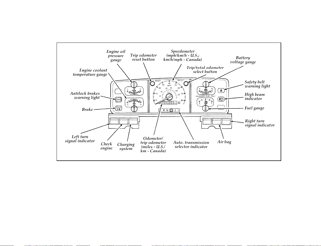
The instrument panel (dashboard) on your
vehicle is divided into several different sections.
The illustrations on the following pages show
the major parts of the instrument panel that are
described in this chapter. Some items shown
may not be on all vehicles.
In your vehicle, the warning lights and gauges
are grouped together on the instrument panel.
We call this grouping a cluster. Your vehicle has
a mechanical cluster.
67
Page 71
68
Mechanical cluster
Page 72
The following warning lights and gauges are on
the mechanical cluster. All of the warning lights
and gauges alert you to possible problems with
your vehicle. Some of the lights listed are
optional. The following sections detail what each
of these indicators means.
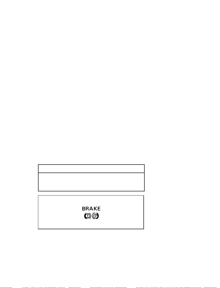
Brake System Warning Light
The red warning light for the brakes can show
three things — that either the parking brake is
not fully released, that the brake fluid level is
low in the master cylinder reservoir or the
vacuum pressure is low on diesel engine
vehicles. If the fluid level is low, the brake
system should be checked by a qualified service
technician.
This light comes on when you turn the ignition
key to START to verify that the indicator bulb is
working. If the light stays on or comes on after
you have released the parking brake fully, have
the hydraulic brake system serviced.
RWARNING
The BRAKE light indicates that the brakes
may not be working properly. Have the
brakes checked immediately.
Brake warning light symbols
69
Page 73
Anti-Lock Brake System Warning Light
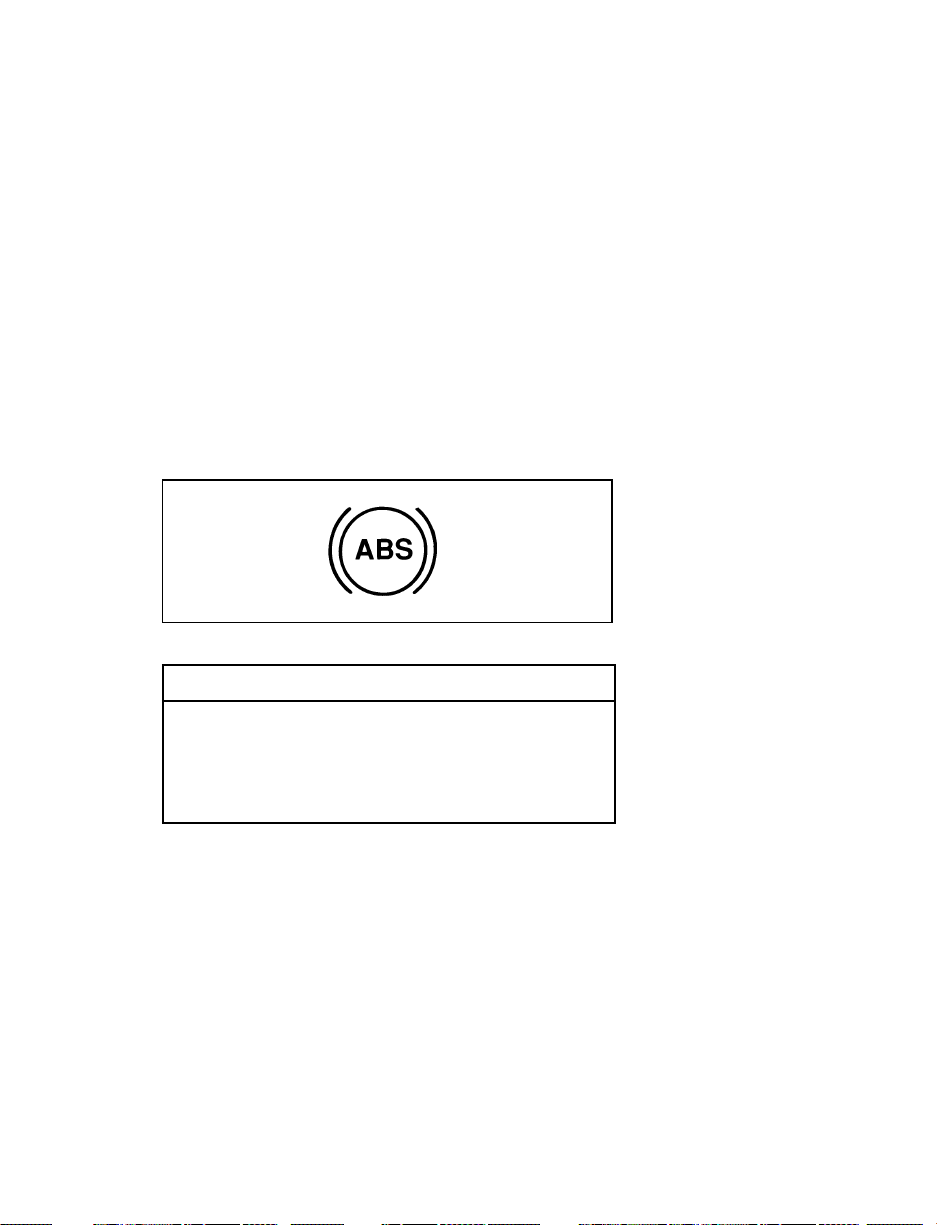
To check the amber ABS brake warning light
turn the ignition key to ON. The ABS brake
warning light should glow momentarily.
NOTE: If it does not glow momentarily, have
your vehicle’s electrical system checked
immediately.
NOTE: If the ABS brake warning light begins
to flash in a repeatable flash sequence,
check the rear anti-lock system
continuous power fuse and brake lights
for proper operation.
Antilock warning light symbol
RWARNING
If the anti-lock brake system warning
light remains on or comes on while
driving, have the braking system checked
by a qualified service technician as soon
as possible.
NOTE: If a fault occurs in the anti-lock
system, and the brake warning light is
not lit, the anti-lock system is disabled
but normal brake function remains
operational.
70
Page 74
Safety Belt Warning Light and Chime
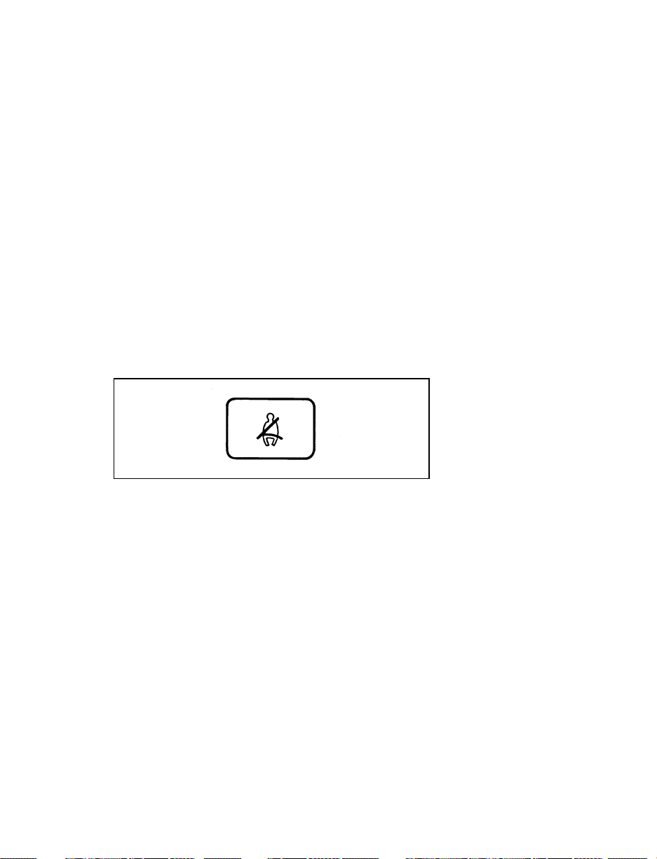
This warning light and chime remind you to
fasten your safety belt. The following conditions
will take place:
If the safety belt is not buckled when the key
❑
is turned to the ON position, the light comes
on for 1 to 2 minutes and the chime sounds
for 4 to 8 seconds.
If the safety belt is buckled while the light is
❑
on and the chime is sounding, both the light
and chime turn off.
If the safety belt is buckled before the
❑
ignition is turned to the ON position, neither
the light nor the chime will come on.
Safety belt warning light symbol
Check Engine Warning Light
The Powertrain On-Board Diagnostic II (OBD II)
system consists of the hardware and software
necessary to monitor the operation of the
powertrain. The OBD II system is designed to
check the function of the vehicle’s powertrain
control system during normal operation. If an
emission problem is detected, the Check Engine
Warning Light (in the cluster) is turned on.
71
Page 75

Check engine warning light symbol
Modification or additions to the vehicle may
cause incorrect operation of the OBD II system.
Additions such as burglar alarms, cellular
phones, and CB radios must be carefully
installed. Do not install these devices by tapping
into or running wires close to powertrain control
system wires or components.
The light comes on briefly when you turn the
ignition key to ON, but it should turn off when
the engine starts. If the light does not come on
when you turn the ignition to ON or if it comes
on and stays on when you are driving, have
your vehicle serviced as soon as possible. This
indicates a possible problem with one of the
vehicle’s emission control systems. You do not
need to have your vehicle towed in.
If the light turns on and off at one (1) second
intervals while you are driving the vehicle, it
means that the engine is misfiring. If this
condition persists, damage could occur to the
engine or catalytic convertor. Have your vehicle
serviced at the first opportunity. You do not
need to have your vehicle towed in.
If the light turns on and off on rare occasions
while you are driving, it means that a
malfunction occurred and the condition corrected
itself.
72
Page 76

An example of a condition which corrects itself
occurs when an engine running out of fuel
begins to misfire. In this case, the Check Engine
Warning Light may turn on and will then set a
Diagnostic Trouble Code indicating that the
engine was misfiring while the last of the fuel
was being consumed. After refueling, the Check
Engine Warning Light will turn off after the
vehicle has completed three consecutive warm
up cycles without a misfire condition occurring.
A warm up cycle consists of engine start from a
cold condition (engine at ambient temperature)
and running until the engine reaches normal
operating temperature.
On the fourth engine start up, the Check Engine
Warning Light will turn off as soon as the
engine begins to crank. It is not necessary to
have the engine serviced.
Under certain conditions, the Check Engine
Warning Light may come on if the fuel cap is
not properly installed. If the Check Engine
Warning Light comes on and you suspect that
the fuel cap is not properly installed, pull off the
road as soon as it is safely possible and turn off
the engine. Remove and replace the fuel cap,
making sure it is properly seated.
After completing the three consecutive warm up
cycles and on the fourth engine start up, the
Check Engine Warning Light should turn off. If
the light does not go off after the fourth engine
restart, have your vehicle serviced by your
dealer or a qualified technician.
73
Page 77
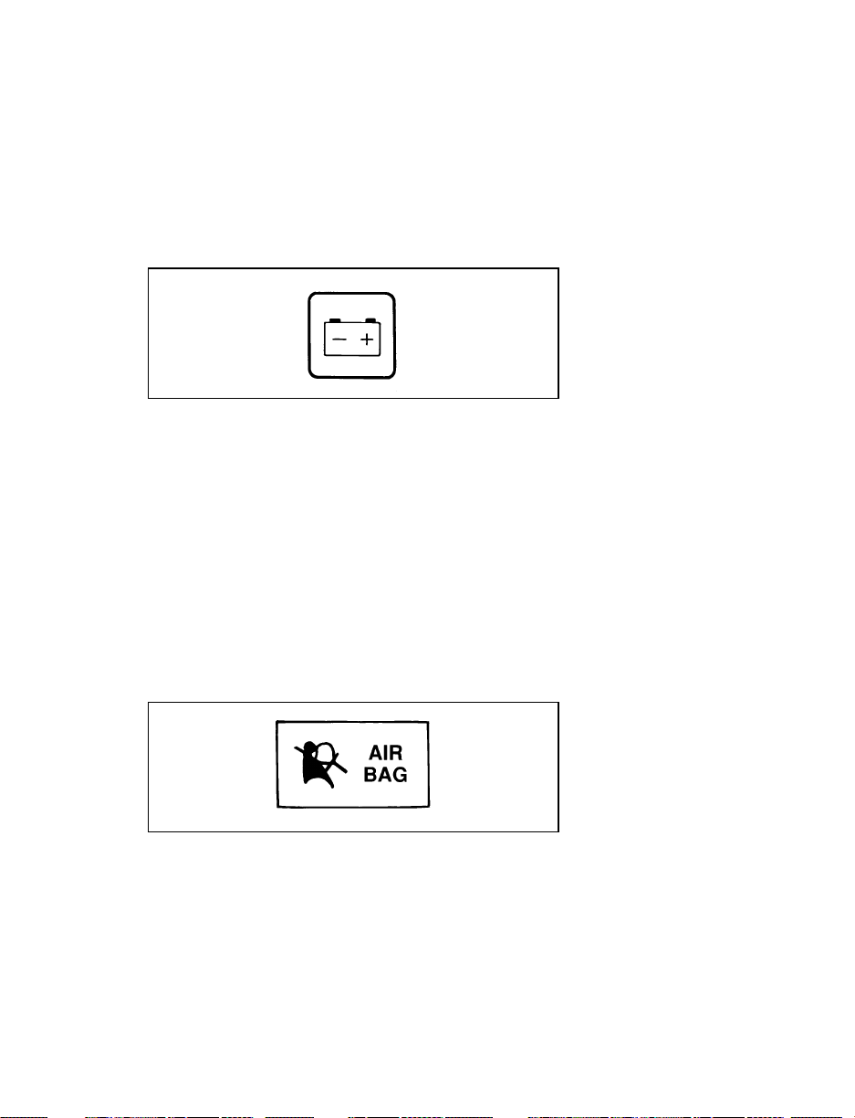
Charging System Light
This light, shown as a battery symbol on your
cluster, indicates that your battery is not being
charged and that you need to have the electrical
system checked.
Charging system light
This light comes on every time you turn the
ignition to the ON or START position (engine
off). The light should go off when the engine
starts and the alternator begins to charge.
Supplemental Air Bag Readiness Light and
Tone Generator
This light illuminates for six seconds when the
ignition is turned to the ON position. If the light
fails to illuminate, continues to flash, remains on,
or if a series of five beeps is heard, have the
system serviced as soon as possible.
Supplemental air bag readiness light
74
Page 78
Anti-Theft Alarm Light (If equipped)
This light flashes on and off when the ignition
switch is OFF and any door is opened. As soon
as you lock the doors, the light glows steadily.
Within 30 seconds of closing all the doors, the
light goes out. This indicates that the alarm
system is armed.
Anti-Theft Alarm Light
Battery Voltage Gauge (Voltmeter)
This gauge shows you the battery voltage when
the ignition key is in the ON position.
If you are running electrical accessories (when
the engine is off, or idling at a low speed), the
pointer may move toward the lower end of the
normal band. If it stays outside the normal band
area, have your vehicle’s electrical system
checked as soon as it is safely possible.
If the battery is operating under cold weather
conditions, the pointer may indicate in the upper
range of the NORMAL band while the battery is
charging. If you are running electrical accessories
with the engine off or idling at a low speed, or
the battery is not fully charged, the pointer may
move toward the lower end of the NORMAL
band.
If it stays outside the NORMAL band, have your
vehicle’s electrical system checked as soon as it
is safely possible.
75
Page 79
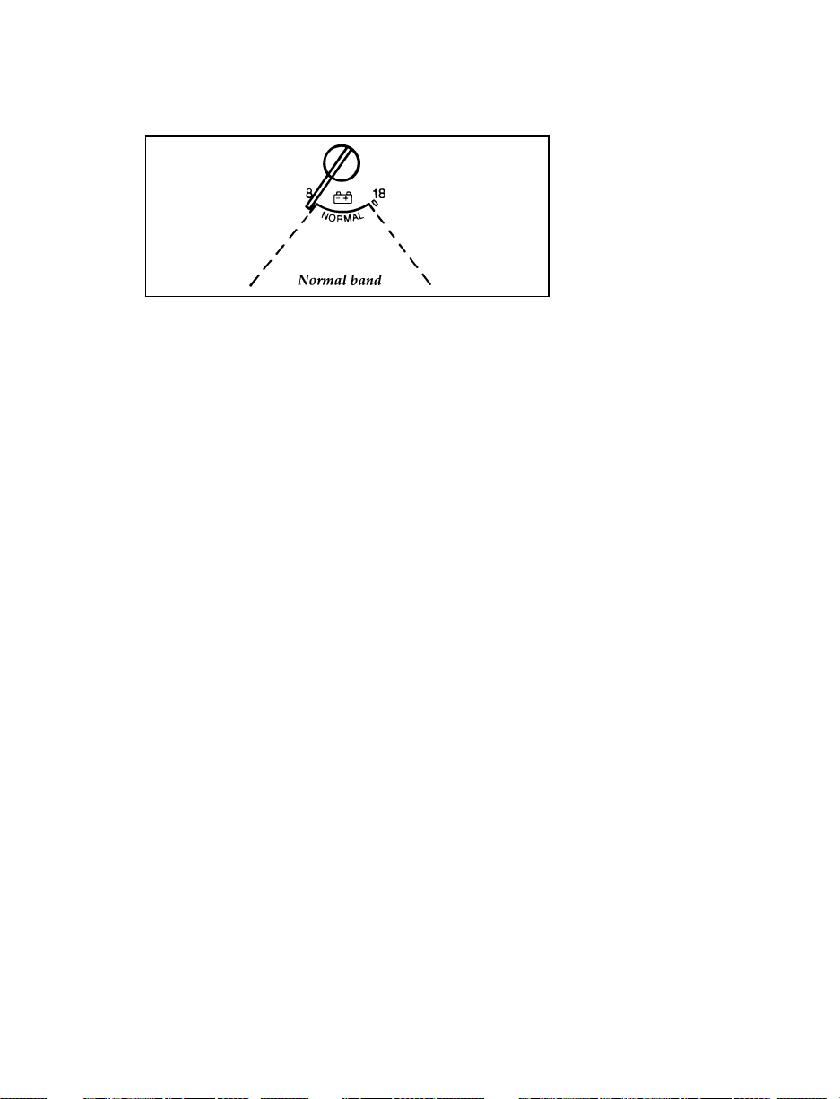
Battery voltage gauge
Engine Oil Pressure Gauge
This gauge indicates the engine’s oil pressure,
not the oil level. However, if your engine’s oil
level is low, it could affect the oil pressure. With
the engine running, the pointer should move
into the NORMAL band. If the pointer drops
below the NORMAL band while the engine is
running, you have lost oil pressure and
continued operation will cause severe engine
damage.
If you lose engine oil pressure:
1. Pull off the road as soon as safely possible.
2. Shut off the engine immediately or severe
engine damage could result.
3. Check the engine’s oil level, following the
instructions on checking and adding engine
oil. Refer to Engine oil in the Index. If you
do not follow these instructions, you or
others could be injured. To assure an
accurate reading, your vehicle should be on
level ground.
4. If the level is low, add only as much oil as
necessary before you start the engine again.
Do not overfill. Do not operate the engine if
the pointer is below the NORMAL band,
regardless of the oil level. Contact your
nearest dealer for further service actions.
76
Page 80
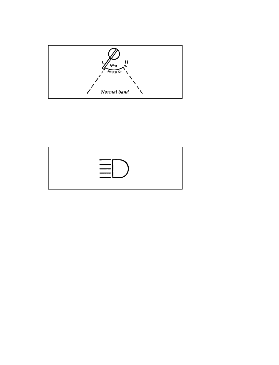
Engine oil pressure gauge
High Beam Light
This light comes on when the headlamps are
turned on high beam or when you flash the
lights.
High beam indicator light
“Headlamps On” Alert Chime
This chime will sound if you open the door
while the headlamps or parklamps are on.
Fuel Gauge
The fuel gauge displays approximately how
much fuel is in the fuel tank only when the
ignition switch is ON.
The fuel gauge indicator may vary slightly when
the vehicle is in motion.
With ignition switch OFF, the fuel gauge
indicator may drift from the ignition switch ON
position.
77
Page 81

Fuel gauge
Engine Coolant Temperature Gauge
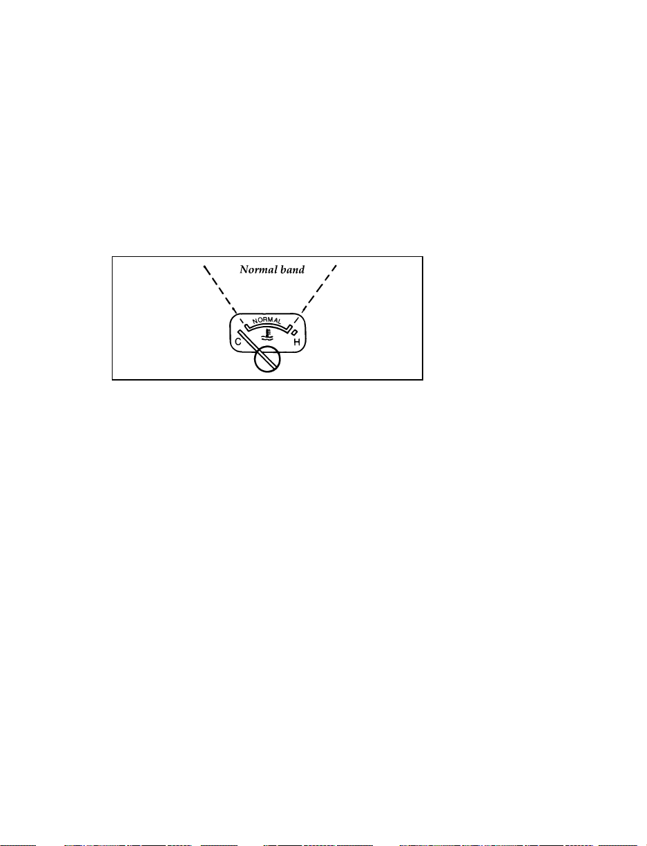
This gauge tells you the temperature of the
engine coolant, not the coolant level. If the
coolant is not at its proper level or mixture, the
gauge indicator will not be accurate.
The pointer moves from the C (cold) mark into
the Normal band as the engine coolant warms
up. It is acceptable for the pointer to fluctuate
within the Normal band under normal driving
conditions. Under certain driving conditions,
such as heavy stop and go traffic or driving up
hills in hot weather, the pointer may indicate at
the top of the Normal band.
If, under any circumstances, the pointer moves
above the NORMAL band, the engine coolant is
overheating and continued operation may cause
engine damage.
If your engine coolant overheats:
1. Pull off the road as soon as it is safely
possible.
2. Turn off the engine. If you do not stop the
engine as soon as safely possible, severe
engine damage could result.
3. Let the engine cool. DO NOT REMOVE
COOLANT SYSTEM FILL CAP UNTIL
THE ENGINE IS COOL.
78
Page 82
4. Check the coolant level following the
instructions on checking and adding coolant
to your engine, see Engine Coolant in the
Index. If you do not follow these
instructions, you or others could be injured.
For instructions on checking and adding coolant
to your engine, see Engine coolant in the Index. If
you do not follow these instructions, you or
others could be injured.
Engine coolant temperature gauge
Speedometer
The speedometer tells you how many miles
(kilometers) per hour your vehicle is moving.
Your vehicle contains a speedometer which
receives its input from the Anti-Lock brake
sensor. The speedometer is also used to provide
a speed signal for correct operation of the
vehicle’s Powertrain Control Module (PCM),
electronic transmission, and speed control (if so
equipped). Because of this, it is very
IMPORTANT to change the speedometer’s
internal conversion constant if the size of the
tires on the vehicle is changed. Changing the
conversion constant to the proper value when
the tires are changed will also ensure that the
speedometer retains the original factory-set
accuracy. NOTE: The conversion constant can
only be changed six times once the vehicle
leaves the factory. Your Ford dealership service
personnel can change the conversion constant.
79
Page 83
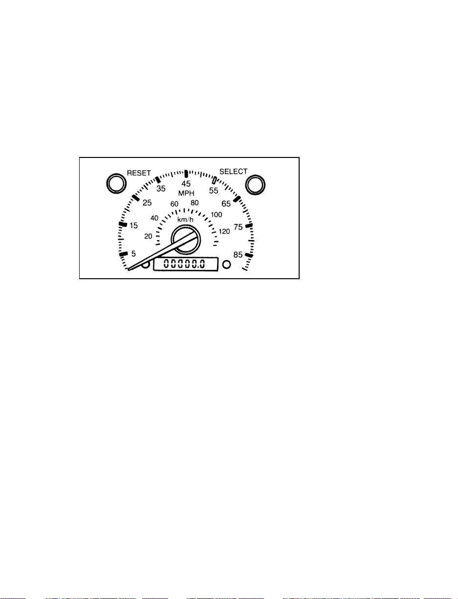
Some vehicles are equipped with a vehicle speed
(MPH/km/h) limiting device that is contained
within the Powertrain Control Module (PCM).
The purpose of this device is to maintain peak
vehicle speed below a specified limit. (Vehicle
speed limits may vary based on engine
displacement).
Speedometer
Odometer/Trip Odometer
The Liquid Crystal Display (LCD) odometer is a
combination trip odometer and total odometer.
The total odometer is normally displayed. To see
the trip odometer, press and release the SELECT
BUTTON on the upper right side of the
speedometer. To zero out the trip odometer,
press and release the RESET button on the
upper left side of the speedometer while the trip
odometer is displayed. If the trip odometer is
displayed, press and release the “Select” button
to return the display to the total odometer value.
80
Page 84

Instrument Panel Controls
NOTE: The following section does not apply
to Stripped Chassis vehicles. See your
Body Builder’s instructions for location
and operation of controls for climate
control systems, lamps, radio and
windshield wiper/washer.
81
Page 85
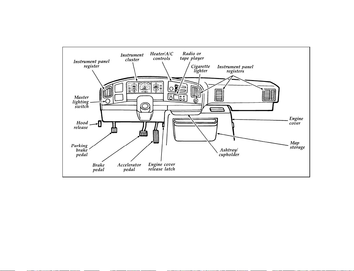
82
Instrument Panel & Controls
Page 86
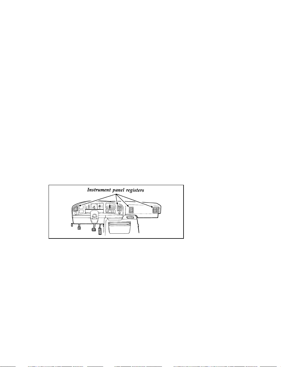
Your vehicle is equipped with a control
assembly designed to handle either a
combination A/C-Heater System or a
Heater-Only System.
If your vehicle has a factory installed auxiliary
system, the front control will be equipped with a
rear fan control switch. If it is a factory installed
auxiliary system with REAR A/C and REAR
HEATER functions, an auxiliary fan speed
control switch is installed in the rear of the
vehicle.
Instrument Panel Registers
There are four registers in the instrument panel.
Each of these registers contains a louver
assembly which can be manually adjusted to
direct airflow up, down, left and right. An
illustration of the register locations follows.
Instrument panel registers
Standard Heater
The control for your Heater system is located at
the center of the instrument panel and will
operate only when the ignition key is turned to
the RUN position. Your Heater will heat or
ventilate your vehicle interior depending on the
Function lever position and temperature you
select. The bottom lever is the Function Selector
lever which allows you to determine where the
83
Page 87
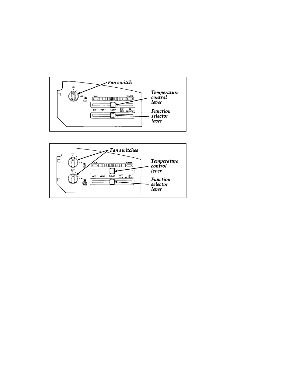
air will be directed. The top lever is the
Temperature lever. The setting or position of the
top lever determines the temperature of the air
that flows into the vehicle.
Front heater only
Front and rear heater only
To turn your Heater system on, move the lower
lever to any position except OFF. This will turn
the fan ON and allow air flow into the vehicle.
To turn your Heater off, move the lower lever to
OFF. This will turn the fan off and stop air flow
from coming into the vehicle.
Temperature selection
The temperature lever is the top lever located
below the broken RED and BLUE band. The
RED part of the band (right side) is the heat or
WARM area. The BLUE area (left side) is the
cool or unheated temperature area. Any position
selected between full right and full left will give
a temperature between the two extreme
temperatures.
84
Page 88

Fan Speed Adjustment
TheHknob (upper left) on the control is the
fan speed knob which controls the volume of air
flow. Rotate theHknob to the right to increase
fan speed and increase the amount of air
entering the vehicle. Four fan speed positions are
available and are indicated by LO, two separate
dots and HI beside theHcontrol knob. The HI
position provides the most air flow.
Airflow selections (lower lever)
VENT
Use VENT to bring outside air through the
instrument panel registers. You can heat the air
in this position by moving the top lever into the
RED area. The air CANNOT be cooled below
the outside temperature.
FLOOR
Air flow will be to the floor when FLOOR is
selected. The air can be heated by moving the
top lever into the RED area.
DEF FLR
Select DEF FLR to get air to the floor and
windshield defrosters at the same time.
VDEFROST
Select V DEFROST to obtain maximum air
flow to the windshield. Move the top lever into
the RED area for the air temperature required to
defrost. Rotate theHknob to increase or
decrease the air flow.
85
Page 89
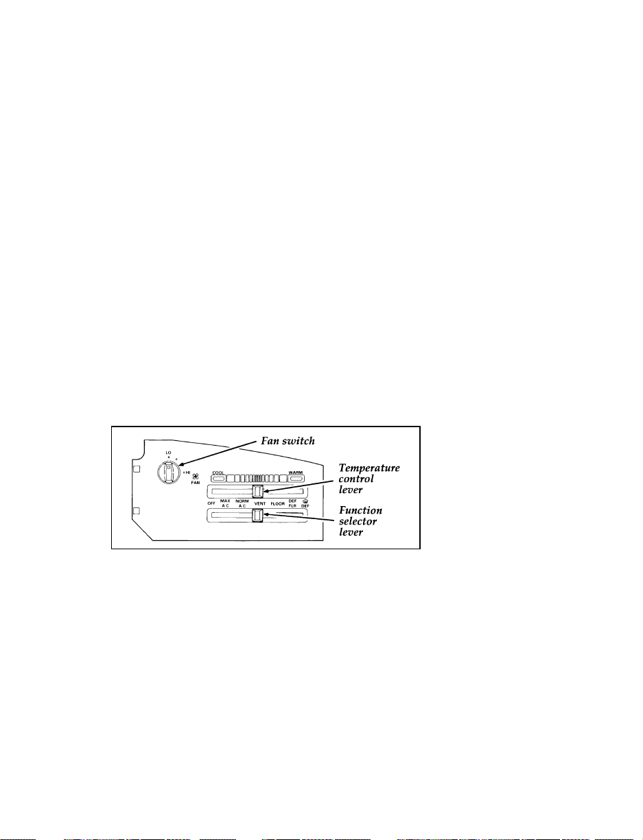
Operating Tips
The following tips will help you to get the most
satisfaction from your heater system.
In humid weather, select V DEFROST. This
❑
will help to prevent windshield fogging. After
a few minutes of operation, you may select
another air flow position.
To prevent humidity buildup inside your
❑
vehicle, always drive with the heater system
turned on.
Do not put objects under the front seats
❑
unless your vehicle is equipped with an
underseat storage tray. Improperly stored
objects will interfere with the flow of air
under the seats to the back seat area.
Remove any snow, ice, or leaves from the air
❑
intake area at the bottom of the windshield.
Front A/C — Heater only (Main system)
86
Page 90
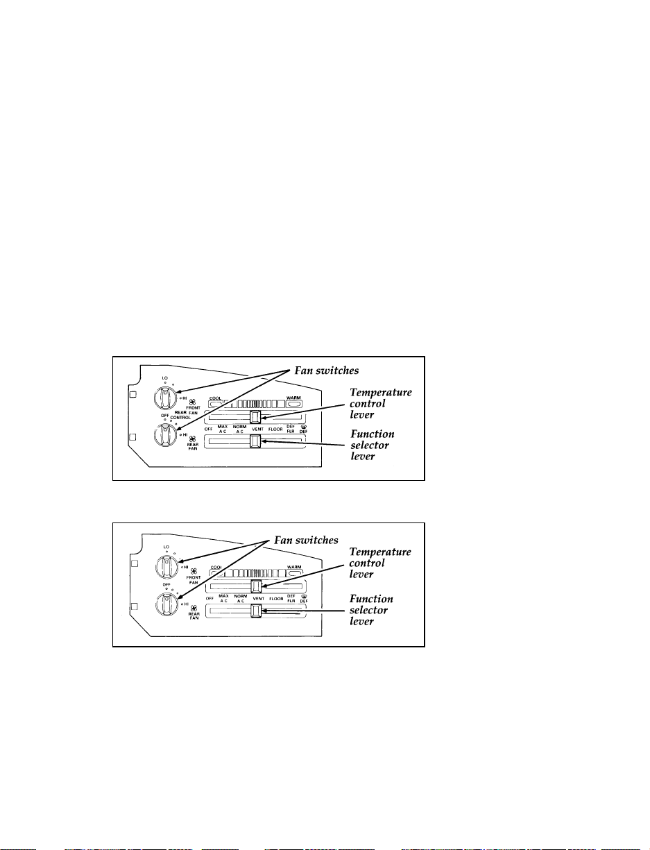
Operational Air Conditioner and Heater
The control for your Air Conditioning and
Heater system is located at the center of the
instrument panel and will operate only when the
ignition key is turned to the RUN position. Your
Air Conditioner & Heater will heat and/or cool
your vehicle interior depending on the Function
lever position and temperature you select. The
bottom lever is the Function Selector lever which
allows you to select heating or cooling and
determine where the air will be directed. The
top lever is the Temperature lever. The setting
or position of the top lever determines the
temperature of the air that flows into the
vehicle.
Front and Rear A/C and Heater (Main and Auxiliary
system)
A/C and Heater, front - Heater only, rear
87
Page 91

To turn your Air Conditioner & Heater system
on, move the lower lever to any position except
OFF. This will turn the fan ON and allow air
flow into the vehicle. To turn your Air
Conditioner & Heater off, move the lower lever
to OFF. This will turn the fan off and stop air
flow from coming into the vehicle.
Temperature selection
The temperature lever is the top lever located
below the broken RED and BLUE band. The
RED part of the band (right side) is the heat or
WARM area. The BLUE area (left side) is the
cooling or COOL temperature area. Any position
selected between full right and full left will give
a temperature between the two extreme
temperatures.
Fan speed adjustment
H
TheHknob (upper left) on the control is the
fan speed knob which controls the volume of air
flow. Rotate theHknob to the right to increase
fan speed and increase the amount of air
entering the vehicle. Four fan speed positions are
available and are indicated by LO, two separate
dots and HI beside theHcontrol knob. The HI
position provides the most air flow.
Airflow selections (lower lever)
VENT
Use VENT to bring outside air through the
instrument panel registers. You can heat the air
in this position by moving the top lever into the
RED area. The air CANNOT be cooled below
the outside temperature regardless of the top
lever setting. Select NORMAL A/C or MAX A/C
to get cooled air through the instrument panel
registers.
88
Page 92

NORM A/C
Select NORM A/C to get refrigerated outside air
through the instrument panel registers. The
NORM A/C position is used for cooling except
when it is extremely hot or fast cooling of the
vehicle is needed. Then, select MAX A/C for
fast cooling and return to NORM A/C when
you are comfortable.
MAX A/C
The MAX A/C position produces cool air more
rapidly to provde faster cooling of your vehicle.
This is possible because cooler air is drawn from
inside the passenger area and then refrigerated
again instead of using warmer outside air. Using
inside air will also make the fan sound louder
which is normal when using MAX A/C. The air
flow will be from the instrument panel registers.
FLOOR
Air flow will be to the floor when FLOOR is
selected. The air cannot be cooled in the FLOOR
position but can be heated by moving the top
lever into the RED area.
DEF FLR
Select DEF FLR to get air to the floor and
windshield defrosters at the same time. If the
outside temperature is about 50˚F (9˚C) or
warmer, the air will also be dehumidified to
remove moisture. This feature will help prevent
fogging in humid weather. The air can be cooled
or heated.
89
Page 93

VDEFROST
Select V DEFROST to obtain maximum air
flow to the windshield. Move the top lever into
the RED area for the air temperature required to
defrost. When the outside temperature is about
50˚F (9˚C) or warmer, the air will be
dehumidified to remove moisture. The air can be
cooled or heated. Rotate theHknob to increase
the air flow.
Operating Tips
The following tips help you get the most
satisfaction from your air conditioner and heater
system:
In humid weather, select V DEFROST. This
❑
will help to prevent windshield fogging. After
a few minutes of operation, you may select
another air flow position.
To prevent humidity buildup inside your
❑
vehicle, always drive with the air conditioner
and heater system turned on.
Do not put objects under the front seats
❑
unless your vehicle is equipped with an
underseat storage tray. Improperly stored
objects will interfere with the flow of air
under the seats to the back seat area.
Remove any snow, ice, or leaves from the air
❑
intake area of your Air Conditioner and
Heater System which could block the air
intake. The intake area is located at the
bottom of the windshield.
90
Page 94

Conditioner (If equipped)
If your vehicle is equipped with a factory
installed auxiliary unit (heater or heater/air
conditioner), the front control assembly will
include separate switches for FRONT and REAR
fan control. Fan speed for front and rear systems
can be set as desired by adjusting these switches.
In addition, on vehicles equipped with auxiliary
A/C, an auxiliary unit fan switch is located in
the headliner at a location between the front and
rear seats.
To control the auxiliary fan with this switch,
❑
the rear fan switch on the front control must
be in the REAR CONTROL position.
NOTE: The air flow from the auxiliary unit is
discharged from the headliner
registers (if so equipped) or the A/C
register (untrimmed vehicles) when
front control selector is in MAX A/C,
NORM A/C and VENT only, and from
floor registers when front control is in
FLOOR FLR/DEF and DEF only.
The auxiliary unit does not provide for
❑
mixing of hot and cold air; adjustment of
temperature in the rear may be accomplished
by increasing or decreasing the rear fan
speed.
91
Page 95
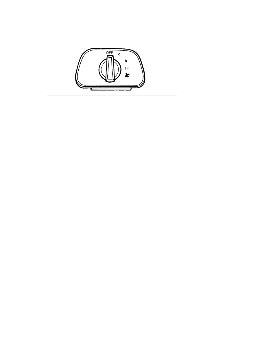
Rear mounted auxiliary fan switch
Turning On the Exterior Lights
To turn on your headlamps, parking lamps,
marker lamps, and tail lamps, use the headlamp
switch to the left of the steering column.
1. Pull the headlamp control knob toward you
to the first position. Parking lamps, tail
lamps and marker lamps are now on.
2. Pull the headlamp control knob toward you
to the outer position. Headlamps are now on
in addition to the above.
3. Rotate the knob when it is in an on position
to brighten or dim the instrument panel
lamps. Rotate fully counterclockwise to
operate courtesy and cargo lamps.
92
Page 96
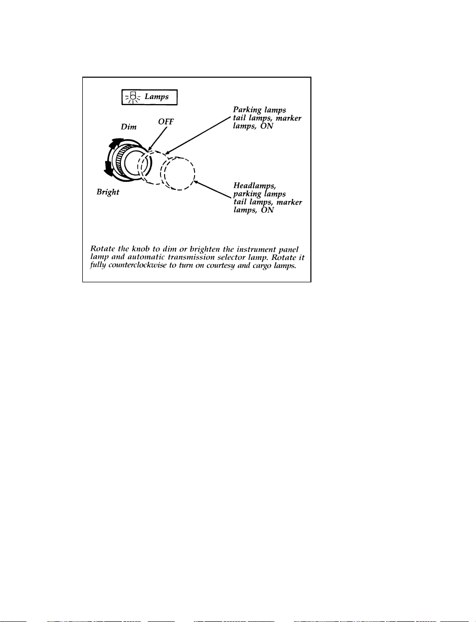
Headlamp switch
Cleaning the Exterior Lamps
Do not use dry paper towel, chemical solvents
or abrasive cleaners to clean the lamps, as these
may cause scratches or crack the lamps.
Daytime Running Light System
(Canadian vehicles only)
The Daytime Running Light (DRL) system turns
the high beam headlamps on, with a reduced
light output, when:
The headlamp system is in the OFF position,
❑
and
The vehicle is running, and
❑
The vehicle has a fully released parking
❑
brake.
93
Page 97

NOTE: You may notice that the lights flicker
when the vehicle is turned on or off.
This is a normal condition.
RWARNING
The Daytime Running Light (DRL) system
will not illuminate the tail lamps and
parking lamps. Turn on your headlamps
at dusk. Failure to do so may result in a
collision.
Lighting Up the Instrument Panel and the
Interior of Your Vehicle
The instrument panel lights can be turned on by
pulling the headlamp switch toward you to
either the first or outer position. You can
brighten or dim the instrument panel lights by
rotating the headlamp switch knob.
Cargo, Courtesy and Dome Lamps
Rear cargo lamps, equipped with an
ON/OFF/DOOR switch will light when the
doors are closed and the switch is in the ON
position.
The standard dome lamp and cargo lamp (with
switch in DOOR position, if so equipped)
operate as courtesy lamps when either front
door is opened. Both the dome lamp and cargo
lamp can be turned on by rotating the headlamp
switch knob.
94
Page 98
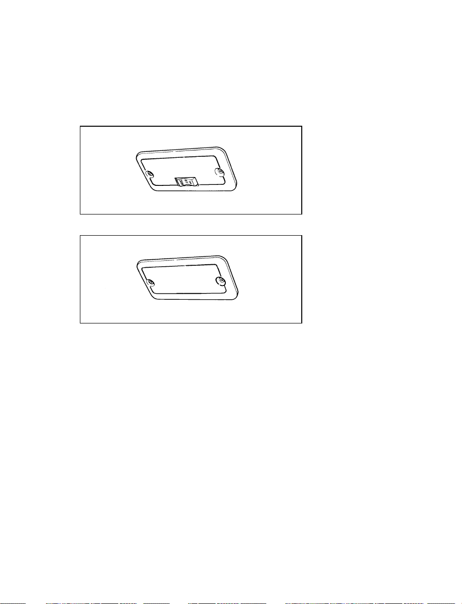
When the cargo lamp switch (if so equipped) is
in the “OFF” position, it will not turn on when
you open the doors or turn the headlamp switch
knob.
Rear cargo lamp with rear headliner
Cargo lamp without rear headliner
95
Page 99
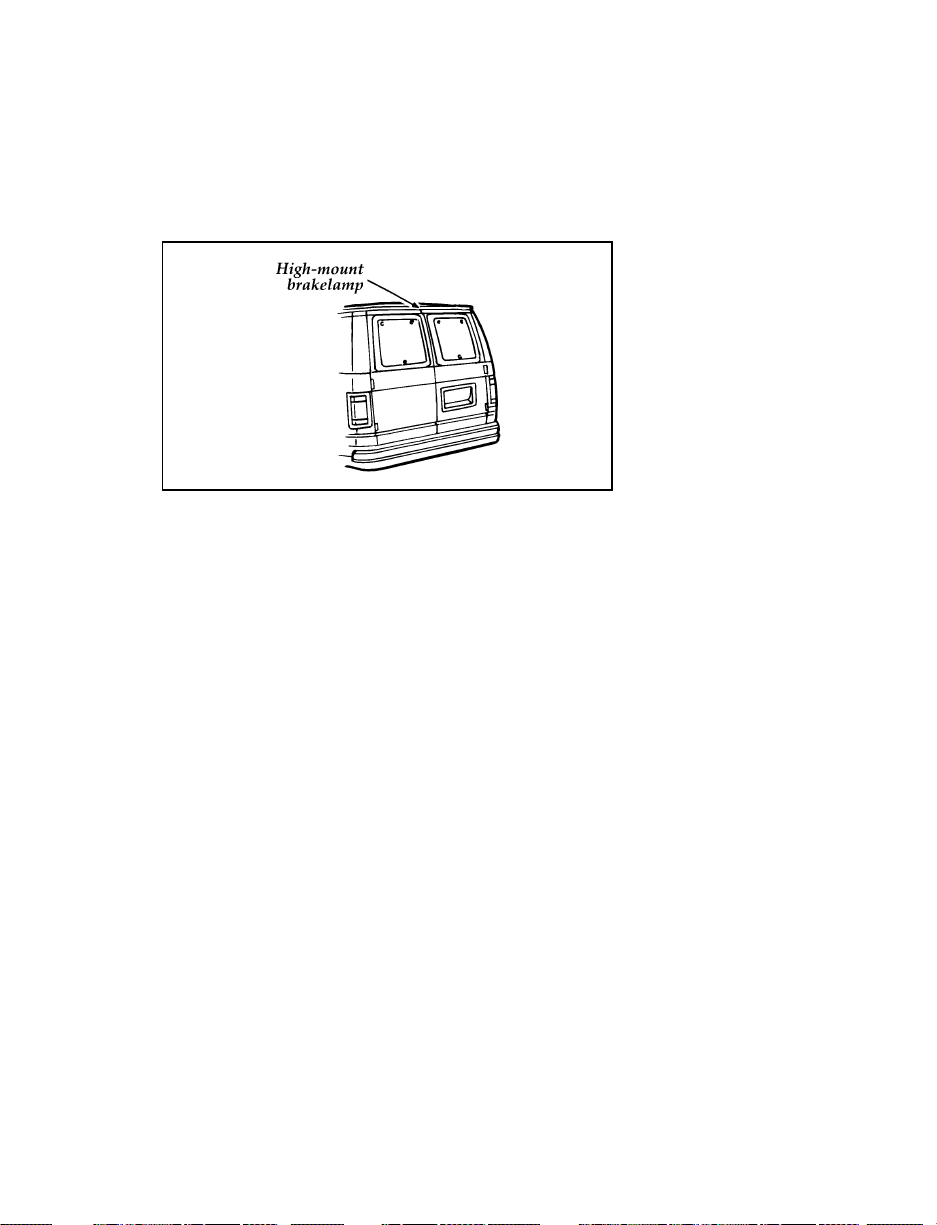
High-mount Brakelamp
The highmount brakelamp is located outside the
vehicle, directly over the rear doors.
Highmount stoplamp
Front and Rear Courtesy/Reading Lamps
Your vehicle may be equipped with either one
courtesy/reading lamp located at the front-center
or three courtesy/reading lamps located at the
front-center, mid-center and rear-center of the
headliner (roof). The right lamps are for the
right side passengers and the left lamps are for
the driver and rear left side passenger.
With the lens in the flat position, the
courtesy/reading lamp will illuminate when any
door is opened or when the headlamp dimmer
knob is rotated to the courtesy lamp position.
With the lens in the rotated position, the
courtesy/reading lamp will illuminate.
96
Page 100
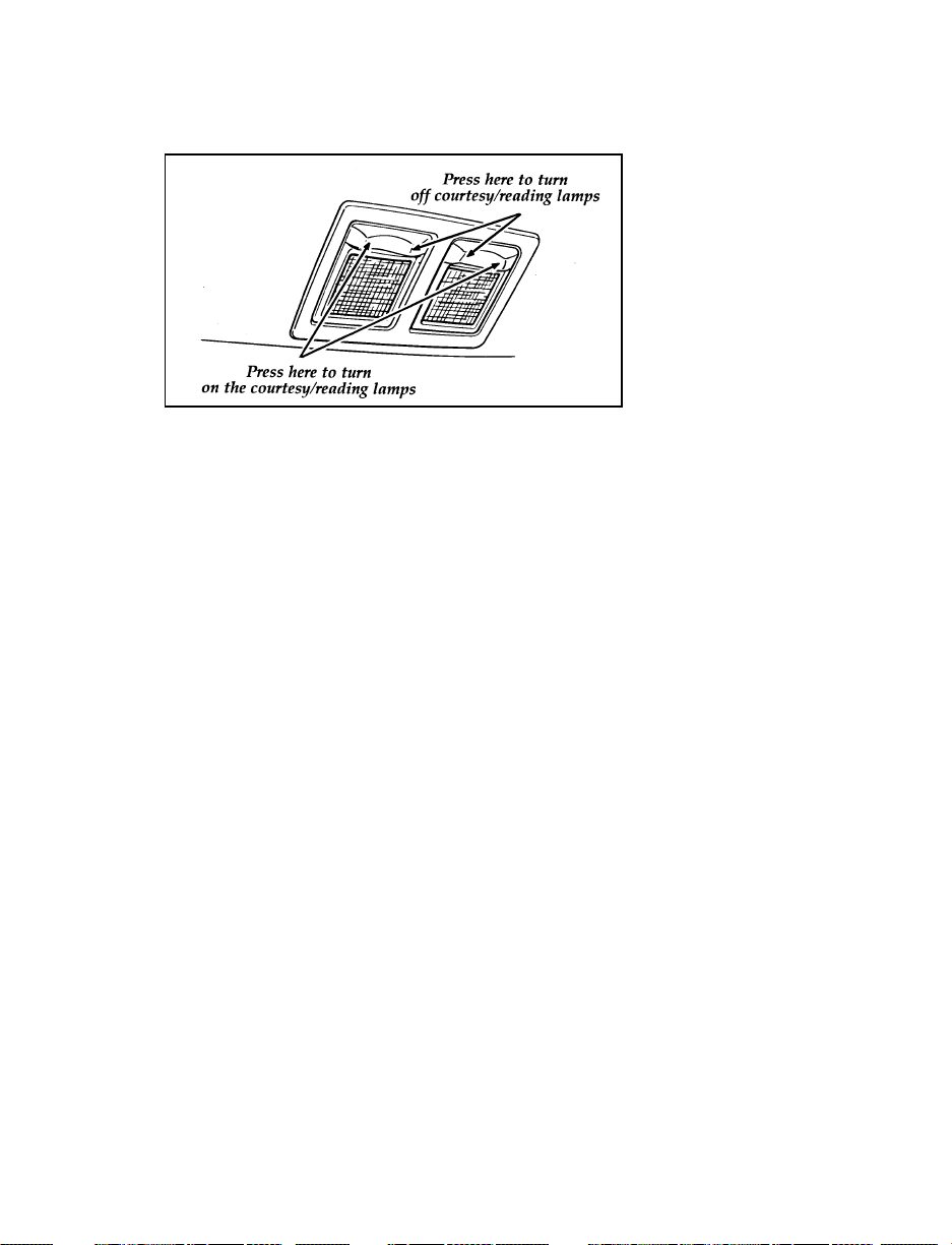
Courtesy/reading lamps
Cleaning the Instrument Panel Lens
Clean the instrument panel lens with a soft cloth
and a glass cleaner, such as Ford Ultra-Clear
Spray Glass Cleaner, or equivalent. Do not use
paper towel or an abrasive cleaner to clean the
lens as these may cause scratches.
Cleaning the Interior Lamps
Your interior dome lamps and map lamps are
plastic and should be cleaned with a mild
detergent diluted in water. Rinse them with clear
water.
97
 Loading...