

Page 1
Page 2
Page 3

Table of Contents
Introductory Information ............................... 1
Safety Restraints .............................................. 7
Starting Your Crown Victoria .................... 37
Warning Lights and Gauges ....................... 47
Instrument Panel Controls .......................... 87
Steering Column Controls ........................ 109
Features .......................................................... 121
Electronic Sound Systems ......................... 149
Driving Your Crown Victoria .................. 173
Roadside Emergencies ................................ 197
Customer Assistance ................................... 215
Reporting Safety Defects ...................... 223
Accessories .................................................... 227
Servicing Your Crown Victoria ............... 233
Quick Index .................................................. 303
Index ............................................................... 313
Service Station Information ...................... 332
Page 4

Introductory Information
Our Guiding Principles
Quality comes first. For your satisfaction, the
❑
quality of our products and services must be
our number one priority.
You are the focus of everything we do. Our
❑
work must be done with you in mind,
providing better products and services than
our competition.
Continuous improvement is essential to our
❑
success. We must strive for excellence in
everything we do: in our products — in their
safety and value — and in our services, our
human relations, our competitiveness, and
our profitability.
Employee involvement is our way of life.
❑
We are a team. We must treat one another
with trust and respect.
Dealers and suppliers are our partners. We
❑
must maintain mutually beneficial
relationships with dealers, suppliers, and our
other business associates.
Integrity is never compromised. Our conduct
❑
worldwide must be pursued in a manner that
is socially responsible and commands respect
for its integrity and for its positive
contributions to society.
1
Page 5

This Guide
Congratulations on the purchase of your new
vehicle. This guide has information about the
equipment and the options for your new vehicle.
You may not have bought all of the options
available to you. If you do not know which
information applies to your vehicle, talk to your
dealer.
This guide describes equipment and gives
specifications for equipment that was in effect
when this guide was approved for printing. Ford
may discontinue models or change specifications
or design without any notice and without
incurring obligation.
NOTES and WARNINGS
NOTES give you additional information about
the subject matter you are referencing.
WARNINGS remind you to be especially careful
in those areas where carelessness can cause
damage to your vehicle or personal injury to
yourself, your passengers or other people. Please
read all WARNINGS carefully.
RWARNING
Finding Information in This Guide
After you have read this guide once, you will
probably return to it when you have a specific
question or need additional information. To help
you find specific information quickly, you can
use the Quick Index or the Index.
2
Page 6

The Quick Index at the end of the book
provides a page number following each item
which indicates where detailed information can
be found.
To use the Index, turn to the back of the book
and search in the alphabetical listing for the
word that best describes the information you
need. If the word you chose is not listed, think
of other related words and look them up. We
have designed the Index so that you can find
information under a technical term.
Canadian Owners — French Version
French Owner Guides can be obtained from your
dealer or by writing to Ford Motor Company of
Canada, Limited, Service Publications, P.O. Box
1580, Station B, Mississauga, Ontario L4Y 4G3.
Record Booklet
The Maintenance Schedule and Record booklet lists
the services that are most important for keeping
your vehicle in good condition. A record log is
also provided to help you keep track of all
services performed.
Your vehicle is covered by three types of
warranties: Basic Vehicle Warranty, Extended
Warranties on certain parts, and Emissions
Warranties.
Read your Warranty Information Booklet carefully
to find out about your vehicle’s warranties and
your basic rights and responsibilities.
If you lose your Warranty Information Booklet, you
can get a new one free of charge. Contact any
Ford or Lincoln-Mercury dealer, or refer to the
3
Page 7

addresses and phone numbers on the first page
of this owner guide.
Buying a Ford Extended Service Plan
If you bought your vehicle in the U.S., you can
buy a Ford Extended Service Plan for your
vehicle. This optional contract provides service
protection for a longer period of time than the
basic warranty that comes with your vehicle.
You do not have to buy this option when you
buy your vehicle. However, your option to
purchase the Ford Extended Service Plan runs
out after 18 months or 18,000 miles. See your
dealer for more details about the Ford Extended
Service Plan.
If you purchased a Canadian vehicle and did not
take advantage of the Ford Extended Service
Plan at the time of purchase, you may still be
eligible. See your dealer for the details.
Your new vehicle goes through an adjustment or
break-in period during the first 1,000 miles
(1,600 km) that you drive it. During the break-in
period, you need to pay careful attention to how
you drive your vehicle.
Avoid sudden stops. Because your vehicle
❑
has new brake linings, you should take these
steps:
— Watch traffic carefully so that you can
anticipate when to stop.
— Begin braking well in advance.
— Apply the brakes gradually.
The break-in period for new brake linings
lasts for 100 miles (160 km) of city driving or
1,000 miles (1,600 km) of highway driving.
4
Page 8

Use only the type of engine oil that Ford
❑
recommends. See Engine oil recommendations
in the Index. Do not use special “break-in”
oils.
Your vehicle is equipped with an Electronic
Powertrain Control Module that limits engine
and/or vehicle speeds with a cut-out mode to
promote durability.
Vehicle
Pollen, bird droppings and tree sap can damage
the paint, especially in hot weather. Wash your
vehicle as often as necessary to keep it clean.
Take similar precautions if your vehicle is
exposed to chemical industrial fallout.
Paint damage resulting from fallout is not
related to a defect in paint materials or
workmanship and therefore is not covered by
warranty. Ford, however, believes that continual
improvement in customer satisfaction is a high
priority. For this reason, Ford has authorized
their dealers to repair, at no charge to the
owner, the surfaces of new vehicles damaged by
environmental fallout within 12 months or 12,000
miles (20,000 km) of purchase, whichever comes
first. Customers may be required to bring their
vehicle in for inspection by a Ford
representative.
5
Page 9

Washing and Polishing Your Vehicle
Wash the outside of your vehicle, including the
underside, with a mild detergent.
DO NOT:
Wash your vehicle with hot water
❑
Wash your vehicle while it sits in direct
❑
sunlight
Wash your vehicle while the body is hot
❑
Polish your vehicle to remove harmful deposits
and protect the finish.
Cleaning Chrome and Aluminum Parts
Wash chrome and aluminum parts with a mild
detergent. Do not use steel wool, abrasive
cleaners, fuel, or strong detergents.
Cleaning Plastic Parts
Some of your vehicle’s exterior trim parts are
plastic. Clean with a tar and road oil remover if
necessary. Use a vinyl cleaner for routine
cleaning.
Do not clean plastic parts with thinners, solvents
or petroleum-based cleaners.
If you have your vehicle rustproofed, remove
oversprayed rustproofing with a tar and road oil
remover. If rustproofing is not removed from
plastic and rubber parts, it can cause
deterioration.
6
Page 10
Safety Restraints
The use of safety belts helps to restrain you and
your passengers in case of a collision. In most
states and in Canada the law requires their use.
Safety belts provide best restraint when:
the seatback is upright
❑
the occupant is sitting upright (not slouched)
❑
the lap belt is snug and low on the hips
❑
the shoulder belt is snug against the chest
❑
the knees are straight forward
❑
To help you remember to fasten your safety belt,
a warning light may come on and a chime may
sound. See Safety Belt Warning Light and Chime in
the Warning Lights and Gauges chapter.
See the following sections in this chapter for
directions on how to properly use these safety
belts. Also see Safety Restraints for Children in this
chapter for special instructions about using
safety belts for children.
RWARNING
Make sure that you and your passengers
wear safety belts. Always drive and ride
with your seatback upright and the lap
belt snug and low across the hips.
7
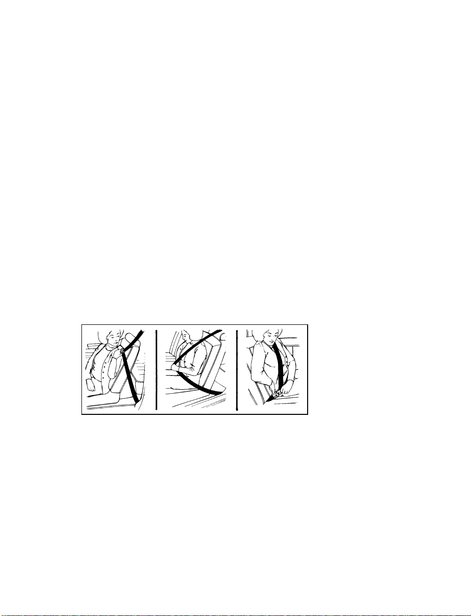
Page 11
RWARNING
Never wear the shoulder belt under the
arm. Never swing it around the neck over
the inside shoulder. Never use a single
belt for more than one person or across
more than one seating position. Each
seating position in your vehicle has a
specific safety belt assembly which is
made up of one buckle and one tongue
that are designed to be used as a pair.
Failure to follow these precautions could
increase the risk and/or severity of injury
in a collision.
RWARNING
Never drive or ride with a twisted or
jammed safety belt. If you cannot untwist
or unjam the safety belt, see the nearest
qualified technician immediately.
RWARNING
To reduce the risk of serious injury in a
collision, children should always ride with
the seatback upright.
RWARNING
Never let a passenger hold a child on his
or her lap while the vehicle is moving.
The passenger cannot protect the child
from injury in a collision.
Lock the doors of your vehicle before driving to
lessen the risk of the door coming open in a
collision.
8
Page 12
Belts
While your vehicle is in motion, the combination
lap and shoulder belt adjusts to your movement.
However, if you brake hard, corner hard or if
your vehicle receives an impact of 5 mph
(8 km/h) or more, the lap and shoulder belt
locks and helps reduce your forward movement.
After you get into your vehicle, close the door
and lock it. Then adjust the seat to the position
that suits you best.
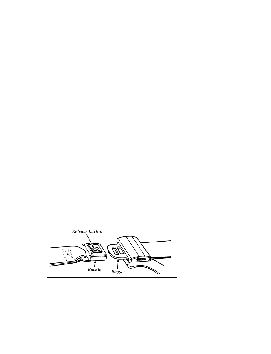
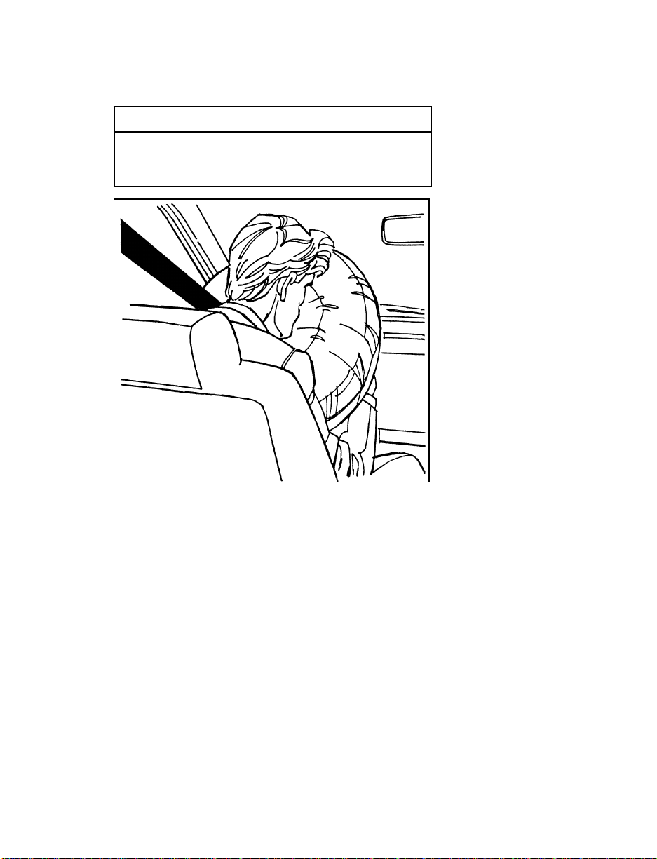
To fasten the belt, pull the lap/shoulder belt
from the retractor so that the shoulder portion of
the belt crosses your shoulder and chest. Be sure
the belt is not twisted. If it is, remove the twist.
Insert the belt tongue into the proper buckle
until you hear a snap and feel it latch. Make
sure the tongue is securely fastened in the
buckle.
Fastening the front seat combination lap and shoulder belt
9
Page 13
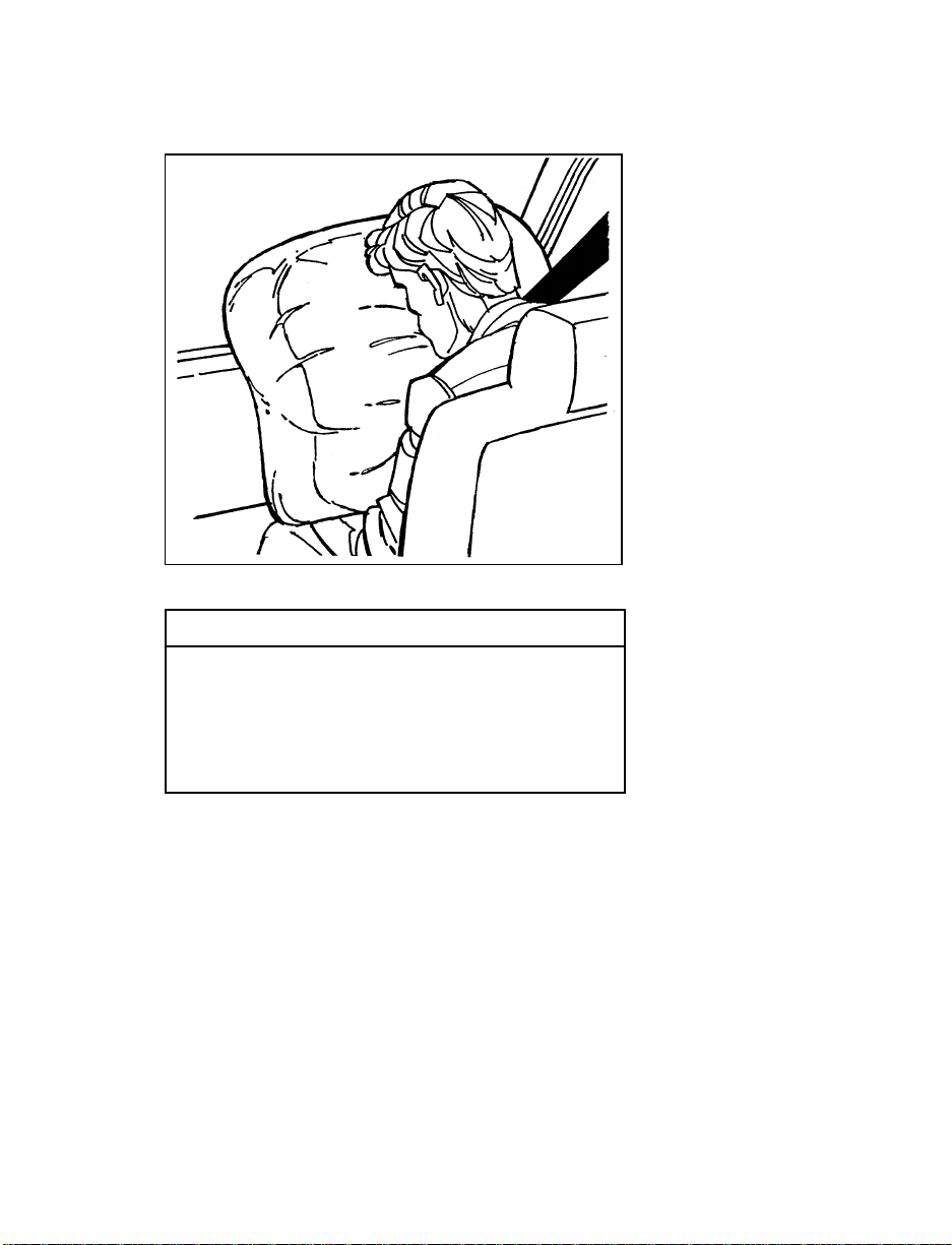
Fastening the rear seat combination lap and shoulder belt
NOTE: Be sure to read and understand
Important Safety Belt Information at
the beginning of this chapter.
Safety Belts for All Passenger Outboard
Seating Positions
Your vehicle is equipped with a dual locking
mode retractor on the shoulder belt portion of
the combination lap/shoulder safety belt for the
front and rear outboard passenger seats.
Dual locking mode retractors operate in two
ways:
Vehicle sensitive (emergency) locking mode
In this operating mode, the shoulder belt
retractor will allow the occupant freedom of
movement, locking tight only on hard braking,
hard cornering or impacts of approximately
5 mph (8 km/h) or more. The retractor can also
be made to lock by pulling/jerking on the belt.
10
Page 14

Automatic locking mode
In this operating mode, the shoulder belt
retractor will be automatically locked and remain
locked when the combination lap/shoulder
safety belt is buckled, and does not allow the
occupant freedom of movement. This mode
provides the following:
A tight lap/shoulder belt fit on the occupant.
❑
Child seat or infant carrier installation
❑
restraint.
RWARNING
Never install a rear-facing child seat or
infant carrier in the right front passenger
seat.
This mode must be used when installing a child
safety seat on the front passenger seat and rear
outboard seats where dual locking retractors are
provided.
To switch the retractor from the emergency
locking mode to the automatic locking mode,
perform the following steps:
1. Buckle the lap/shoulder combination belt.
2. Grasp the shoulder portion of the belt and
pull downward until all of the belt is
extracted, and when allowed to retract, a
clicking sound will be heard. At this time,
the belt retractor is in the automatic locking
mode (child restraint mode).
3. A clicking sound will contnue to be heard as
the belt is allowed to retract.
11
Page 15

NOTE: When the combination lap/shoulder
belt is unbuckled and allowed to
retract completely, the retractor will
switch back to the vehicle sensitive
(emergency) locking mode. See the
detailed instructions under Safety Seats
for Children in this chapter.
Shoulder Belt Height Adjustment
Driver and right front passenger
You can adjust the shoulder belt height to one of
five (5) positions. To adjust, pinch the release
button (see Figures 1 and 2) and slide it up or
down until the belt rests across the middle of
your shoulder. Release the button and make sure
the adjuster is firmly in one of the five (5)
positions.
RWARNING
If the shoulder belt is off your shoulder
or on your upper arm, there is a greater
risk of severe injury in a collision.
BE SURE THE BELT IS PROPERLY
POSITIONED ON YOUR SHOULDER EACH
TIME YOU USE THE BELT.
12
Page 16
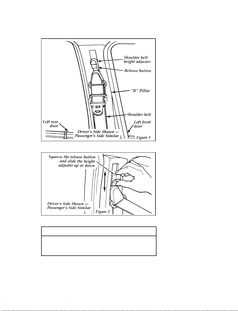
The shoulder belt height adjuster
The shoulder belt height adjuster
RWARNING
The lap belts should fit snugly and as low
as possible around the hips, not around
the waist.
13
Page 17
RWARNING
All front and rear seat outboard
occupants (including pregnant women)
should wear lap and shoulder belts, for
optimum protection in a collision.
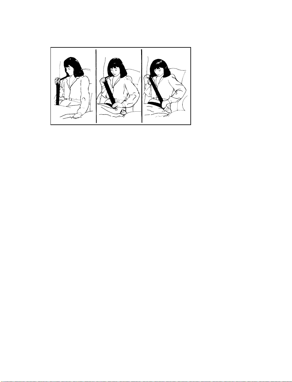
RWARNING
Failure to follow these precautions could
increase the risk and/or severity of injury
in a collision. 1) Use the shoulder belt on
the outside shoulder only. Never wear the
shoulder belt under the arm. 2) Never
swing it around your neck over the inside
shoulder. 3) Never use a single belt for
more than one person.
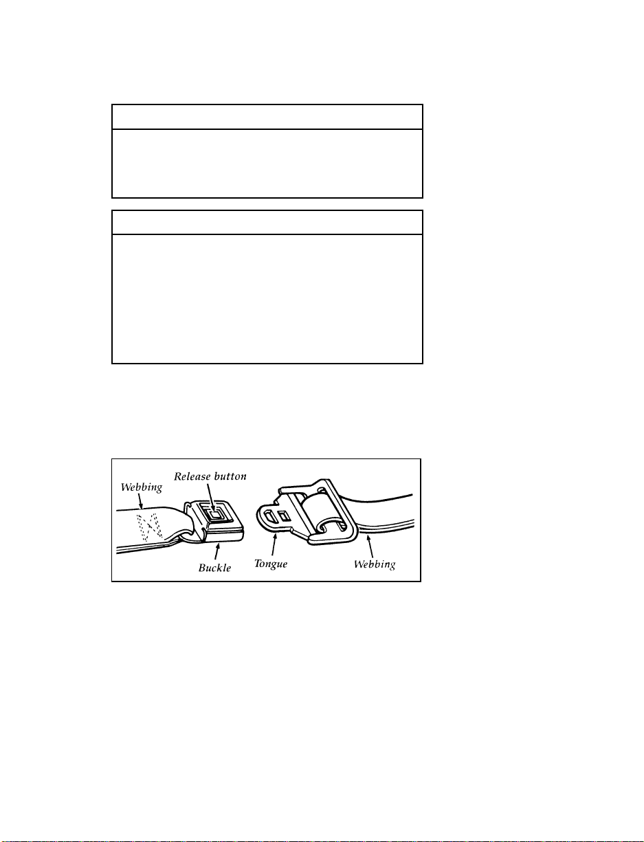
To unfasten all the belts:
1. Push the release button in the center of the
buckle. This allows the tongue to unlatch
from the buckle.
Unfastening the outboard lap/shoulder belts
2. While the belt retracts, guide the tongue to
its stowed position. If you do not guide the
tongue, it may strike you or part of the
vehicle.
14
Page 18
Lap Belts — Center Seating
Position
The lap belts in the center of the front and rear
seats do not adjust automatically. You must
adjust them to fit snugly and as low as possible
around your hips. Do not wear them around
your waist.
Pull the belt across your hips and insert the
tongue into the correct buckle on your seat
until you hear a snap and feel it lock. Make sure
the buckle is securely fastened.
If you need to lengthen the belt, unfasten it and
tip the belt tongue at a right angle to the belt.
Pull the belt tongue over your lap until it
reaches the buckle.
If you need to shorten the belt, pull on the loose
end of the webbing until the belt fits snugly.
To unfasten the belt, push the release button on
the buckle. This allows the tongue to unlatch
from the buckle.
Because the center lap belts do not have
retractors, they should be shortened and fastened
when not in use.
Unfastening center lap safety belts
15
Page 19

Safety Belt Extension Assembly
For some people, the safety belt may be too
short even when it is fully extended. You can
add about eight inches (20 cm) to the belt length
with a safety belt extension assembly (part
number 611C22). Safety belt extensions are
available at no cost from your dealer.
RWARNING
Failure to follow these instructions will
affect the performance of the safety belts
and increase the risk of personal injury.
Use only extensions manufactured by the same
supplier as the safety belt. Manufacturer
identification is located at the end of the
webbing on the label. Also, use the safety belt
extension only if the safety belt is too short for
you when fully extended. Do not use extension
to change the fit of the shoulder belt across the
torso.
Safety Belt Maintenance
Check the safety belt systems periodically to
make sure that they work properly and are not
damaged.
All safety belt assemblies, including retractors,
buckles, front seat belt buckle support assemblies
(slide bar) (if equipped), child safety seat tether
bracket assemblies (if equipped), and attaching
hardware, should be inspected after any
collision. Ford recommends that all safety belt
assemblies used in vehicles involved in a
collision be replaced. However, if the collision
was minor and a qualified technician finds that
the belts do not show damage and continue to
operate properly, they do not need to be
replaced. Safety belt assemblies not in use
16
Page 20
during a collision should also be inspected and
replaced if either damage or improper operation
is noted.
Cleaning the Safety Belts
Clean the safety belts with any mild soap
solution that is recommended for cleaning
upholstery or carpets. Do not bleach or dye the
belt webbing because this may weaken it.
System (SRS)
The driver and right front passenger air bags are
Supplemental Restraint Systems (SRS), provided
at these seating positions in addition to the
lap/shoulder belt, and are designed to
supplement the protection provided to properly
belted occupants in moderate to severe frontal
collisions. The supplemental air bag system does
not provide restraint to the lower body.
The Importance of Wearing Safety Belts
RWARNING
Safety belts must be worn by all vehicle
occupants to be properly restrained and
help reduce the risk of injury in a
collision.
RWARNING
All occupants of the vehicle, including the
driver, should always wear their safety
belts, even when an air bag Supplemental
Restraint System is provided.
17
Page 21
There are four very important reasons to use
safety belts even with an air bag system. Use
your safety belts to:
help keep you in the proper position (away
❑
from the air bag) when it inflates
reduce the risk of harm in rollover, side or
❑
rear impact collisions, because an air bag is
not designed to inflate in such situations
reduce the risk of harm in frontal collisions
❑
that are not severe enough to activate the
supplemental air bag
reduce the risk of being thrown from your
❑
vehicle
The Importance of Being Properly Seated
In a collision, the air bag must inflate extremely
fast to help provide additional protection for
you. In order to do this, the air bag must inflate
with considerable force. If you are not seated in
a normal riding position with your back against
the seatback, the air bag may not protect you
properly and could possibly hurt you as it
inflates.
RWARNING
If a passenger is not properly seated and
restrained, an inflating air bag could cause
serious injury.
RWARNING
Rear-facing infant seats should never be
placed in the front seat.
18
Page 22

In rear-facing infant seats, the infant’s head is
closer to the air bag. The force of the rapidly
inflating air bag could push the top of the
rear-facing seat against the vehicle seatback,
center console (if so equipped), or center
armrests (if so equipped). REAR-FACING
INFANT SEATS MUST ALWAYS BE SECURED
IN THE REAR SEAT, and other child safety
seats and infant seats should be secured in the
rear seat whenever possible.
Your vehicle is equipped with a right front
passenger air bag. Air bags deploy with great
force, faster than the blink of an eye. Front
passengers, especially children and small adults,
must never sit on the front edge of the seat,
stand near the glove compartment of the
instrument panel, or lean over near the air bag
cover when the vehicle is moving. All occupants
should sit with their backs against the seatback,
move the seat to the most rearward position if
possible and use the safety belts. Children
weighing less than 40 lbs. (18 kg) always should
use child or infant seats.
RWARNING
When using forward-facing child seats
move the passenger seat as far back from
the instrument panel as possible. NEVER
SECURE REAR-FACING INFANT SEATS
IN THE FRONT SEAT.
THE FORCE OF THE RAPIDLY INFLATING
PASSENGER AIR BAG COULD PUSH THE TOP
OF THE REAR-FACING SEAT AGAINST THE
VEHICLE SEATBACK, ARMRESTS OR
CONSOLE. REAR-FACING INFANT SEATS
MUST ALWAYS BE SECURED IN THE REAR
SEAT.
19
Page 23

RWARNING
Do not place objects or mount equipment
on or near the air bag cover on the
steering wheel or in front seat areas that
may come in contact with a deploying air
bag. Failure to follow this instruction may
increase the risk of personal injury in the
event of a collision.
For additional important safety information on
the proper use of seat belts, child seats, and
infant seats, please read the other sections of this
part of the Owner Guide, especially sections
entitled Safety Belts for Children and Safety Seats
for Children.
For further information about the proper
mounting of equipment in the front seat of this
vehicle, please refer to Ford’s brochure entitled
Some Important Information About Air Bag
Supplemental Restraint System which can be
obtained by calling Helm Inc. at 1-800-782-4356.
Ask for brochure FPS-8602.
How the Air Bag Supplemental Restraint
System Operates
The driver air bag is in the center of the steering
wheel. The right front passenger seat air bag is
in the upper right hand section of the
instrument panel ledge above the glove
compartment. Both air bags are designed to stay
out of sight until they are activated.
20
Page 24
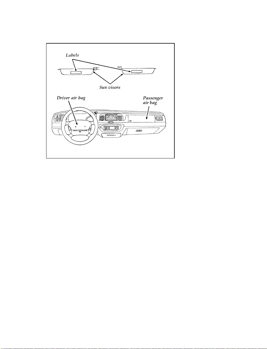
The location of the air bag and warning labels
If a collision occurs, the sensors sense the
severity of the impact and activates the air bags
if necessary. The air bag system is designed to
deploy in frontal and front-angled collisions
more severe than hitting a parked vehicle (of
similar size and weight) head-on at about
28 mph (45 km/h). Because the system senses
the crash severity rather than vehicle speed,
some frontal collisions at speeds above 28 mph
(45 km/h) will not inflate the air bag.
The whole inflation and deflation process takes
place in a matter of seconds.
21
Page 25
RWARNING
Air bag system components get hot after
inflation. Do not touch them after
inflation.
Inflated driver side air bag
22
Page 26
Inflated right front passenger side air bag
RWARNING
If the air bag is inflated, THE AIR BAG
WILL NOT FUNCTION AGAIN AND
MUST BE REPLACED IMMEDIATELY. If
the air bag is not replaced, the unrepaired
area will increase the risk of injury in a
collision.
The air bag system uses a readiness light and a
tone to indicate the condition of the system. The
readiness light is in the instrument cluster. When
you turn the ignition to the ON position, this
light will illuminate for approximately six (6)
seconds and then turn off. This indicates that the
system is operating normally. NOTE:
Maintenance of the air bag system is not
required.
23
Page 27

A problem with the system is indicated by one
or more of the following:
the readiness light will either flash or stay lit,
❑
or
it will not light immediately after the ignition
❑
is turned on, or
a group of five beeps will be heard.
❑
If any of these things happen, have the air bag
system serviced at your Ford or Lincoln-Mercury
dealer immediately. Unless serviced, the air bag
supplemental restraint system may not function
properly in the event of a collision.
RWARNING
Do not attempt to service, repair, or
modify the Air Bag Supplemental
Restraint System or its fuses. See your
Ford or Lincoln-Mercury dealer.
Disposal of air bags or air bag equipped
vehicles
For disposal of air bags or air bag equipped
vehicles, see your local Ford or Lincoln-Mercury
dealer. Air bags MUST be disposed of by
qualified personnel.
In the U.S. and Canada, you are required by law
to use safety restraints for children. If small
children ride in your vehicle — this generally
includes children who are four years old or
younger and who weigh 40 pounds (18 kg) or
less — you must put them in safety seats that
are made specially for children. Safety belts
alone do not provide maximum protection for
these children. Check your local and state laws
for specific requirements.
24
Page 28
RWARNING
Never let a passenger hold a child on his
or her lap while the vehicle is moving.
The passenger cannot protect the child
from injury in a collision.
RWARNING
Passengers should not be allowed to ride
in the cargo area. Persons not riding in a
seat with a fastened seat belt are much
more likely to suffer serious injury in a
collision. Cargo should always be secured
to prevent it from shifting and causing
damage to the vehicle or harm to
passengers.
When possible, put children in the rear seat of
your vehicle. Accident statistics suggest that
children are safer when properly restrained in
the rear seating positions than in the front
seating positions.
RWARNING
Carefully follow all of the manufacturer’s
instructions included with the safety seat
you put in your vehicle. If you do not
install and use the safety seat properly,
the child may be injured in a sudden stop
or collision.
RWARNING
Safety belts and seats can become hot in a
vehicle that has been closed up in sunny
weather; they could burn a small child.
Check seat covers and buckles before you
place a child anywhere near them.
25
Page 29
RWARNING
Never leave a child unattended in your
vehicle.
RWARNING
When using forward-facing child seats
move the passenger seat as far back from
the instrument panel as possible. NEVER
SECURE REAR-FACING INFANT SEATS
IN THE FRONT SEAT.
Safety Seats for Children
Use a safety seat that is recommended for the
size and weight of the child. Always follow the
safety seat manufacturer’s instructions when
installing and using the safety seat.
Ford recommends the use of a child safety seat
having a top tether strap. Install the child safety
seat in a seating position which is capable of
providing a tether anchorage. For more
information on top tether straps see your Ford
or Lincoln-Mercury dealer.
When installing a child safety seat, be sure to
use the correct safety belt buckle for that seating
position, and make sure the tongue is securely
fastened in the buckle.
26
Page 30
Children weighing less than 40 lbs. (18 kg)
should use child or infant seats. Forward facing
child seats must have the passenger seat moved
as far back from the instrument panel as
possible.
RWARNING
REAR-FACING INFANT SEATS SHOULD
NEVER BE USED IN THE FRONT SEAT.
REAR-FACING INFANT SEATS MUST
ALWAYS BE PLACED IN THE REAR
SEAT. Failure to follow these instructions
could result in serious injury.
All child restraint systems are designed to be
secured in vehicle seats by lap belts or by the
lap portion of a lap-shoulder belt.
RWARNING
If you do not properly secure the safety
seat, the child occupying the seat may be
injured during a collision or sudden stop.
An unsecured safety seat could also injure
other passengers.
RWARNING
Carefully follow all of the manufacturer’s
instructions included with the safety seat
you put in your vehicle. If you do not
install and use the safety seat properly,
the child may be injured in a sudden stop
or collision.
27
Page 31

Installing Safety Seats in the Front and
Rear Outboard Passenger Seating Positions
For seating positions equipped with a dual
locking mode retractor, use the following
procedure.
If you choose to install a child safety seat or
infant carrier in the front seating positions, move
vehicle seat as far back as possible.
1. Position the child seat in the center of the
passenger seat.
2. Pull down on shoulder belt, then grasp
shoulder belt and lap belt together. Figure 1.
28
Page 32

3. While holding the shoulder and lap belt
portions together, route the tongue through
the child seat according to the child seat
manufacturer’s instructions. See Figure 2. Be
sure that the belt webbing is not twisted.
Routing the lap/shoulder belt
29
Page 33

4. Insert the belt tongue into the buckle for that
seating position until you hear and feel the
latch engage. Figure 3. Make sure tongue is
latched securely to buckle by pulling on
tongue.
Buckling the belt
30
Page 34

5. Grasp the shoulder portion of the belt and
pull downward until all of the belt is
extracted and a click is heard. At this time,
the retractor is in the automatic locking
mode (child seat restraint mode). Figure 4.
NOTE: The dual-locking mode retractor must
be in the automatic locking mode to
properly restrain a child.
Setting the retractor to automatic locking mode
6. Allow the belt to retract. Pull up on the
shoulder webbing. A clicking sound will be
heard as the belt retracts. This indicates the
retractor is in the automatic locking mode.
Push down on the child seat while you pull
up on the belt to remove any slack in the
belt. Figures 5 and 6.
31
Page 35

32
Page 36

7. Before placing the child in the child seat,
forcibly tilt the seat from side to side, and
tug it forward to make sure that the seat is
securely held in place, Figure 7.
Checking that the seat is secure
8. Double check that the retractor is in the
automatic locking mode. Try to pull more
belt out of the retractor. If you cannot, the
belt is in the automatic locking mode,
Figure 8.
33
Page 37

Checking the retractor
9. Check to make sure that the child seat is
properly secured prior to each use. If the
retractor is not locked, repeat steps 4
through 7.
Installing a Child Safety Seat at the Rear
Center Seating Position with Adjustable
Lap Belt
1. Lengthen the lap belt. To lengthen the belt,
hold the tongue so that its bottom is
perpendicular to the direction of webbing
while sliding the tongue up the webbing.
2. Place the child safety seat in the center
seating position.
3. Route the tongue and webbing through the
child seat according to the child seat
manufacturer’s instructions.
34
Page 38

4. Insert the belt tongue into the proper buckle
for the center seating position until you hear
a snap and feel it latch. Make sure the
tongue is securely fastened to the buckle by
pulling on tongue.
5. Push down on the child seat while pulling
on the loose end of the lap belt webbing to
tighten the belt.
6. Before placing the child into child seat,
forcibly tilt the child seat from side-to-side
and in forward direction to ensure that the
seat is held securely in place. If the child
seat moves excessively, repeat steps 5
through 6, or properly install the child seat
in a different position.
Safety Belts for Children
Children who are too large for child safety seats
should always wear safety belts. (See instructions
with your child seat, or contact its manufacturer,
to determine maximum size of child that will
safely fit in the seat.)
RWARNING
If safety belts are not properly worn and
adjusted as described, the risk of serious
injury to the child in a collision will be
much greater.
If the shoulder belt position of one of the lap
and shoulder belts can be positioned so that it
does not cross or rest in front of the child’s face
or neck, the child should wear the lap and
shoulder belt. Moving the child closer to the
center of the vehicle may help provide a good
shoulder belt fit.
35
Page 39

RWARNING
If the shoulder belt cannot be properly
positioned, the child should sit in the
center rear seat and use the lap belt or, if
that seat is unavailable, in the center front
seat and use the lap belt.
To improve the fit of lap and shoulder belts on
children who have outgrown child safety seats,
Ford recommends use of a belt-positioning
booster seat that is labelled as conforming to all
Federal motor vehicle safety standards.
Belt-positioning booster seats raise the child and
provide a shorter, firmer seating cushion that
encourages safer seating posture and better fit of
lap and shoulder belts on the child. A
belt-positioning booster should be used if the
shoulder belt rests in front of the child’s face or
neck, or if the lap belt does not fit snugly on
both thighs, or if the thighs are too short to let
the child sit all the way back on the seat cushion
when the lower legs hang over the edge of the
seat cushion. You may wish to discuss the
specific needs of your child with your
pediatrician.
RWARNING
Do not use a belt-positioning booster with
a lap-only belt.
Lap belts and the lap belt portion of lap and
shoulder belts should always be worn snugly
and below the hips, touching the child’s thighs.
RWARNING
To reduce the risk of serious injury in a
collision, children should always ride with
the seatback upright.
36
Page 40

Warning Lights and Gauges
The instrument panel (dashboard) on your
vehicle is divided into several different sections.
The illustrations on the following pages show
the major parts of the instrument panel that are
described in this chapter. Some items shown
may not be on all vehicles.
In your vehicle, the warning lights and gauges
are grouped together in the instrument cluster
and the indicator lamp module.
Your vehicle is equipped with one of the
following clusters:
a mechanical cluster
❑
an electronic cluster
❑
47
Page 41

48
The mechanical cluster
Page 42

The following warning lights and gauges are on
the mechanical cluster. All of the warning lights
and gauges alert you to possible problems with
your vehicle. Some of the lights listed are
optional. The following sections detail what each
of these indicators means.
Brake System Warning Light
The warning light for the brakes can show two
things — that the parking brake is not fully
released, or that the brake fluid level is low in
the master cylinder reservoir. If the fluid level is
low, the brake system should be checked by a
qualified service technician.
This light comes on when the parking brake is
set, or if it is not set, it comes on briefly when
you turn the ignition key to START. It normally
goes off shortly after the engine starts and you
release the parking brake. If the light stays on
after you have fully released the parking brake,
have the hydraulic brake system serviced.
RWARNING
The BRAKE light indicates that the brakes
may not be working properly. Have the
brakes checked immediately.
49
Page 43

Anti-Lock Brake System Light
(If equipped)
This warning light will go on each time you
start your vehicle. If it remains on for longer
than five seconds, you should shut off your
engine and restart. If the anti-lock brake light
stays on, this indicates that the anti-lock feature
is disabled and should receive immediate
attention by a qualified service technician.
Normal braking is not affected unless the brake
warning light is also lit.
The Anti-Lock Brake System has self-check
capabilities. As previously described, the system
turns on the anti-lock light each time you start
your engine. After the engine is started and the
anti-lock light is out, the system performs
another test the first time the vehicle reaches
14 mph (22 km/h). The system turns on the
Anti-Lock Brake System (ABS) pump motor for
approximately 1/2 second. At this time a
mechanical noise may be heard. This is a normal
part of the self-check feature. If a malfunction is
found during this check the anti-lock light will
come on.
50
Page 44

RWARNING
If the anti-lock brake system warning
light remains on or comes on while
driving, have the braking system checked
by a qualified service technician as soon
as possible.
NOTE: If a fault occurs in the anti-lock
system, and the brake warning light is
not lit, the anti-lock system is disabled
but normal brake function remains
operational.
Safety Belt Warning Light and Chime
This warning light and chime remind you to
fasten your safety belt. The following conditions
will take place:
If the driver’s safety belt is not buckled when
❑
the ignition is turned to the ON position, the
light will turn on for 1 to 2 minutes and the
chime will sound for 4 to 8 seconds.
If the driver’s safety belt is buckled while the
❑
light is on or the chime is sounding, both the
light and the chime will turn off.
If the driver’s safety belt is buckled before the
❑
ignition is turned to the ON position, neither
the light nor the chime will turn on.
51
Page 45

Air Bag Readiness Light
The air bag system uses a readiness light to
indicate the condition of the system. If the
system is functioning properly, the light will
stay on for 6 seconds when the ignition switch is
turned to the ON position.
If there is a problem with the system, two things
may happen: the readiness light will either flash
or stay lit up, or you will hear a beeping sound.
If either of these things happen, have the air bag
system serviced at your Ford or Lincoln-Mercury
dealer immediately.
Charging System Light
This light indicates that your battery is not being
charged and that you need to have the electrical
system checked.
This light comes on every time you turn the
ignition to the ON or START position (engine
off). The light should go off when the engine
starts and the alternator begins to charge.
52
Page 46

If the light stays on or comes on when the
engine is running, have the electrical system
checked as soon as possible.
Overdrive Off Indicator
This light tells you that the Transmission Control
Switch (TCS) on the gearshift lever has been
pushed. When the light is on, the transmission
will not shift into overdrive. Depressing the
button on the shifter will return the vehicle to
“overdrive on” mode. The transmission will be
in the “overdrive on” mode when the vehicle is
started even if the O/D OFF mode was selected
when the vehicle was last shut off.
NOTE: If the light does not come on when the
TCS is depressed or if the light flashes
when you are driving, have your
vehicle serviced at the first
opportunity. If this condition persists,
damage could occur to the
transmission.
53
Page 47

High Beam Light
This light comes on when the headlamps are
turned to high beam or when you flash the
lights.
Low Fuel Alert Light
This light comes on when your fuel gauge
indicates between 1/8 and 1/16 of a tank. Your
car must be turned to ON for this light to come
on.
54
Page 48

Air Suspension Light (If equipped)
This light tells you if the air suspension needs
repair or if the air suspension switch (in the
trunk on the right side) is OFF.
Normally, the light will glow momentarily as
you turn the ignition key to the ON position. If
it glows continuously:
1. Safely pull off the road as soon as possible.
Turn the ignition key from ON to OFF and
ON again.
2. If the light still glows, check to see if the air
suspension switch is OFF. If it is OFF, push
the switch ON. If it is ON, push the switch
OFF and have the system checked as soon as
possible.
Check Engine Warning Light
The Powertrain On-Board Diagnostic II (OBD II)
system consists of the hardware and software
necessary to monitor the operation of the
powertrain. The OBD II system is designed to
check the function of the vehicle’s powertrain
control system during normal operation. If an
emission problem is detected, the Check Engine
Warning Light (in the cluster) is turned on.
Modification or additions to the vehicle may
cause incorrect operation of the OBD II system.
Additions such as burglar alarms, cellular
phones, and CB radios must be carefully
55
Page 49

installed. Do not install these devices by tapping
into or running wires close to powertrain control
system wires or components.
The light comes on briefly when you turn the
ignition key to ON, but it should turn off when
the engine starts. If the light does not come on
when you turn the ignition to ON or if it comes
on and stays on when you are driving, have
your vehicle serviced as soon as possible. This
indicates a possible problem with one of the
vehicle’s emission control systems. You do not
need to have your vehicle towed in.
If the light turns on and off at one (1) second
intervals while you are driving the vehicle, it
means that the engine is misfiring. If this
condition persists, damage could occur to the
engine or catalytic convertor. Have your vehicle
serviced at the first opportunity. You do not
need to have your vehicle towed in.
If the light turns on and off on rare occasions
while you are driving, it means that a
malfunction occurred and the condition corrected
itself.
An example of a condition which corrects itself
occurs when an engine running out of fuel
begins to misfire. In this case, the Check Engine
Warning Light may turn on and will then set a
Diagnostic Trouble Code indicating that the
engine was misfiring while the last of the fuel
was being consumed. After refueling, the Check
56
Page 50

Engine Warning Light will turn off after the
vehicle has completed three consecutive warm
up cycles without a misfire condition occurring.
A warm up cycle consists of engine start from a
cold condition (engine at ambient temperature)
and running until the engine reaches normal
operating temperature.
On the fourth engine start up, the Check Engine
Warning Light will turn off as soon as the
engine begins to crank. It is not necessary to
have the engine serviced.
Under certain conditions, the Check Engine
Warning Light may come on if the fuel cap is
not properly installed. If the Check Engine
Warning Light comes on and you suspect that
the fuel cap is not properly installed, pull off the
road as soon as it is safely possible and turn off
the engine. Remove and replace the fuel cap,
making sure it is properly seated.
After completing the three consecutive warm up
cycles and on the fourth engine start up, the
Check Engine Warning Light should turn off. If
the light does not go off after the fourth engine
restart, have your vehicle serviced by your
dealer or a qualified technician.
Turn Signal Indicator Lights
The turn signal arrow will flash to indicate the
direction in which you are going to be turning.
57
Page 51

Fuel Gauge
The fuel gauge
The fuel gauge displays approximately how
much fuel is in the fuel tank only when the
ignition switch is ON. For proper fuel gauge
indication after adding fuel, turn the ignition
switch OFF while refueling the vehicle.
The fuel gauge indicator may vary slightly when
the vehicle is in motion. The most accurate
reading is obtained with the vehicle on level
ground.
With ignition switch OFF, the fuel gauge
indicator may drift from the ignition switch ON
position.
Engine Coolant Temperature Gauge
This gauge indicates the temperature of the
engine coolant, not the coolant level. If the
coolant is not at its proper level or mixture, the
gauge indication will not be accurate.
The pointer moves from the C (cold) mark into
the NORMAL band as your engine coolant
warms up. Under normal driving conditions, the
pointer should stay in the NORMAL band. It is
acceptable for the pointer to fluctuate within the
NORMAL band under normal driving
58
Page 52

conditions, and under certain driving conditions
such as, heavy stop and go traffic, or driving up
hills in hot weather, for the pointer to indicate at
the top of the NORMAL band.
If, under any circumstances, the pointer moves
above the NORMAL band, the engine is
overheating and continued operation may cause
engine damage.
The engine coolant temperature gauge
If your engine coolant overheats:
1. Pull off the road as soon as safely possible.
2. Turn off the engine.
3. Let the engine cool. DO NOT REMOVE
COOLANT SYSTEM FILL CAP UNTIL
THE ENGINE IS COOL.
4. Check the coolant level following the
instructions on checking and adding coolant
to your engine, see Engine Coolant in the
Index. If you do not follow these
instructions, you or others could be injured.
If the coolant continues to overheat, have the
coolant system serviced.
59
Page 53

Speedometer
The speedometer tells you how many miles
(kilometers) per hour your vehicle is moving.
Odometer
The odometer tells you the total number of miles
(kilometers) your vehicle has been driven.
Trip Odometer
If you want to track your mileage up to 999.9
miles (kilometers), use the trip odometer. Simply
set the trip odometer to zero by pressing the
reset button firmly when beginning the distance
you wish to measure.
Since the trip odometer displays distance
independent of the odometer it will not always
advance to the next mile (kilometer) at the same
time as the odometer.
Battery Voltage Gauge (If Equipped)
This gauge shows you the battery voltage when
the ignition key is in the ON position.
If the battery is operating under cold weather
conditions, the pointer may indicate in the upper
range of the NORMAL band while the battery is
charging. If you are running electrical accessories
(when the engine is off, or idling at a low
speed), the pointer may move toward the lower
end of the NORMAL band.
If it stays outside the NORMAL band, have your
vehicle’s electrical system checked as soon as it
is safely possible.
60
Page 54

The battery voltage gauge
Engine Oil Pressure Gauge
This gauge indicates the engine oil pressure, not
the oil level. However, if your engine’s oil level
is low, it could affect the oil pressure. With the
engine running, the pointer should move into
the NORMAL band. If the pointer drops below
the NORMAL band while the engine is running,
you have lost oil pressure and continued
operation will cause severe engine damage.
If you lose engine oil pressure:
1. Pull off the road as soon as safely possible.
2. Shut off the engine immediately or severe
engine damage could result.
3. Check the engine’s oil level, following the
instructions on checking and adding engine
oil, see the Engine Oil in the Index. If you do
not follow these instructions, you or others
could be injured. To assure an accurate
reading, your car should be on level ground.
4. If the level is low, add oil as necessary
before you start the engine again. Do not
overfill. Do not operate the engine if the
pointer is below the NORMAL band,
regardless of the oil level. Contact your
nearest dealer for further service actions.
61
Page 55

For more information about adding oil, see
Engine Oil Recommendations in the Index.
The electronic cluster works only when your
ignition is in the ON position. Each time you
start your vehicle, the displays go through a
self-test by flashing on and off once before the
actual readings are displayed. (Neither the turn
signals nor the high beam indicator light will
flash like the other indicators do for the
self-test.) Some of the warning lights will flash
on and remain on (will not immediately flash
off) until the normal cluster display is lit. This
self-test is used to indicate that all of the
warning/indicator lights are working properly.
Your electronic cluster tells you about the
condition of your vehicle by using two types of
equipment:
warning lights and gauges
❑
message center
❑
62
Page 56

63
Electronic cluster
Page 57

Engine Coolant Temperature Gauge
This gauge indicates the engine coolant
temperature not the coolant level. If the coolant
is not at its proper level or mixture, the gauge
indication will not be accurate. It is identified by
a thermometer symbol, an “H” (hot), and a “C”
(cold). The “NORMAL” indicates the normal
operating range. The bars will move into the
normal operating range as the engine coolant
warms up. It is acceptable under certain driving
conditions such as, heavy stop and go traffic, or
driving up hills in hot weather, for the gauge to
indicate at the top of the NORMAL band.
If, under any circumstance, the pointer moves
above the NORMAL band, the temperature
symbol flashes and a tone will sound to alert the
driver that the engine coolant is overheating and
continued operation may cause engine damage.
If your engine coolant overheats:
1. Pull off the road as soon as it is safely
possible.
2. Turn off the engine. If you do not stop the
engine as soon as safely possible, severe
engine damage could result.
64
Page 58

3. Let the engine cool. DO NOT REMOVE
COOLANT SYSTEM FILL CAP UNTIL
THE ENGINE IS COOL.
4. Check the coolant level following the
instructions on checking and adding coolant
to your engine, see Engine Coolant in the
Index. If you do not follow these
instructions, you or others could be injured.
If the coolant continues to overheat, have the
coolant system serviced.
If only the top two and bottom two bars appear
on the gauge, then the system is indicating that
it requires servicing. Contact your dealer for
service as soon as possible.
Safety Belt Warning Light and Chime
This warning light and chime remind you to
fasten your safety belt. The following conditions
will take place:
If the driver’s safety belt is not buckled when
❑
the ignition is turned to the ON position, the
light will turn on for 1 to 2 minutes and the
chime will sound for 4 to 8 seconds.
If the driver’s safety belt is buckled while the
❑
light is on or the chime is sounding, both the
light and the chime will turn off.
If the driver’s safety belt is buckled before the
❑
ignition is turned to the ON position, neither
the light nor the chime will turn on.
65
Page 59

High Beam Light
This light comes on when the headlamps are
turned to high beam or when you flash the
lights.
Check Engine Warning Light
The Powertrain On-Board Diagnostic II (OBD II)
system consists of the hardware and software
necessary to monitor the operation of the
powertrain. The OBD II system is designed to
check the function of the vehicle’s powertrain
control system during normal operation. If an
emission problem is detected, the Check Engine
Warning Light (in the cluster) is turned on.
Modification or additions to the vehicle may
cause incorrect operation of the OBD II system.
Additions such as burglar alarms, cellular
phones, and CB radios must be carefully
installed. Do not install these devices by tapping
into or running wires close to powertrain control
system wires or components.
66
Page 60

The light comes on briefly when you turn the
ignition key to ON, but it should turn off when
the engine starts. If the light does not come on
when you turn the ignition to ON or if it comes
on and stays on when you are driving, have
your vehicle serviced as soon as possible. This
indicates a possible problem with one of the
vehicle’s emission control systems. You do not
need to have your vehicle towed in.
If the light turns on and off at one (1) second
intervals while you are driving the vehicle, it
means that the engine is misfiring. If this
condition persists, damage could occur to the
engine or catalytic convertor. Have your vehicle
serviced at the first opportunity. You do not
need to have your vehicle towed in.
If the light turns on and off on rare occasions
while you are driving, it means that a
malfunction occurred and the condition corrected
itself.
An example of a condition which corrects itself
occurs when an engine running out of fuel
begins to misfire. In this case, the Check Engine
Warning Light may turn on and will then set a
Diagnostic Trouble Code indicating that the
engine was misfiring while the last of the fuel
was being consumed. After refueling, the Check
Engine Warning Light will turn off after the
vehicle has completed three consecutive warm
up cycles without a misfire condition occurring.
A warm up cycle consists of engine start from a
cold condition (engine at ambient temperature)
and running until the engine reaches normal
operating temperature.
On the fourth engine start up, the Check Engine
Warning Light will turn off as soon as the
engine begins to crank. It is not necessary to
have the engine serviced.
67
Page 61

Under certain conditions, the Check Engine
Warning Light may come on if the fuel cap is
not properly installed. If the Check Engine
Warning Light comes on and you suspect that
the fuel cap is not properly installed, pull off the
road as soon as it is safely possible and turn off
the engine. Remove and replace the fuel cap,
making sure it is properly seated.
After completing the three consecutive warm up
cycles and on the fourth engine start up, the
Check Engine Warning Light should turn off. If
the light does not go off after the fourth engine
restart, have your vehicle serviced by your
dealer or a qualified technician.
Air Bag Readiness Light
The Air Bag Readiness light will go on each
time you start your vehicle and will remain on
for about 6-8 seconds indicating normal air bag
operation. If this light stays on continuously or
flashes, or if the light never comes on at all,
there is something wrong with the Air Bag
Supplemental Restraint System and your vehicle
should be taken in for service to the nearest
Lincoln-Mercury dealer as soon as possible.
Unless serviced, the Air Bag Supplemental
Restraint System may not function properly in
the event of a collision.
68
Page 62

Charging System Warning Light
This light comes on when you turn your ignition
key from OFF to ON. The light should go out
when the engine starts and the alternator begins
to charge.
If this light stays on or comes on while your
engine is running, this tells you that your
battery is not being charged and that you need
to have the electrical system checked as soon as
possible.
Engine Oil Pressure Light
This light indicates the engine oil pressure, not
the oil level. However, if your engine’s oil level
is low, it could affect the oil pressure. The light
should come on every time your ignition key is
turned to ON or START, and should go out
when the engine starts. If the light stays on or
turns on while the engine is running, you have
lost oil pressure and continued operation will
cause severe engine damage.
69
Page 63

If you lose engine oil pressure:
1. Pull off the road as soon as safely possible.
2. Shut off the engine immediately. If you do
not stop the engine as soon as safely
possible, severe engine damage could result.
3. Check the engine’s oil level, following the
instructions on checking and adding engine
oil, see Engine Oil in the Index. If you do
not follow these instructions, you or others
could be injured. To assure an accurate
reading, your vehicle should be on level
ground.
4. If the level is low, add only as much oil as
necessary before you start the engine again.
Do not overfill. Do not operate the engine if
the light is on, regardless of the oil level.
Contact your nearest dealer for service as
soon as possible.
For more information about adding oil, see
Adding engine oil in the Servicing Your Vehicle
chapter of this guide.
Turn Signal Indicator Lights
The turn signal arrow will flash to indicate the
direction in which you are going to be turning.
70
Page 64

Speed Control Indicator Light
This light comes on when the speed control
system is actively maintaining the set speed. It
will go off when the brakes are used or if the
speed control is turned off.
This light does not indicate any problems but is
only a convenience to tell when the speed
control is active.
Fuel Gauge
The fuel gauge tells you approximately how
many gallons/liters of fuel you have in the tank.
When your tank reaches 1/8 or approximately
2 gallons (8 liters), a flashing fuel pump will
appear.
Turn the ignition switch off while fueling to
obtain an accurate fuel gauge indication.
71
Page 65

NOTE: At least 2.5 gallons (9.5 liters) of fuel
must be added for the fuel gauge to
immediately show the new level of
fuel. If less than 2.5 gallons (9.5 liters)
of fuel is added, the gauge will reach
the new level slowly.
If the fuel gauge displays only the top two bars
and the bottom two bars, or, if fuel remaining or
distance to empty functions display CO or CS,
then there is a problem. Take your vehicle in for
service.
When you turn the ignition key to the ON or
ACC position, all the display segments will light
up, then go off for a second indicating the gauge
is working. Then the gauge will show you how
much fuel you have in the tank.
FUEL REMAIN — Fuel Remaining
This function shows you how many gallons
(liters) of fuel you have left in the fuel tank.
If your fuel level is above 20 gallons (76 liters),
the letter “F” (full) will appear on the display.
But if your fuel level has dropped to below
1 gallon (4 liters), the letter “E” (empty) will
appear in the display.
Because of factors like rounding of numbers and
fuel movement in the tank, your fuel gauge and
the service station fuel pump readings may
disagree slightly.
72
Page 66

A problem is indicated if the fuel gauge bar
graph displays only the top two and bottom two
bars and the message center display for Distance
To Empty or Fuel Remaining functions display
the letters “CO” or “CS”. If this happens, contact
your dealer for service as soon as possible.
Speedometer
The speedometer tells you how many miles
(kilometers) per hour your vehicle is moving. It
indicates the speed up to 120 mph or up to
195 km/h.
You can press the E/M (English/Metric) button
located just below the message center display to
show the speed you are going in either miles
per hour or kilometers per hour.
Odometer
The odometer tells you the total number of miles
or kilometers your vehicle has been driven. If
the cluster is replaced, and the accumulated
mileage on the odometer is unknown, the
replacement cluster will have the circled “S”
illuminated with zero miles on the odometer. If
the actual vehicle mileage can be verified, then
an authorized service center can program the
actual mileage into the odometer of the
replacement cluster. The actual mileage (if
known) or an estimated mileage (if unknown) is
shown on a label affixed on the door pillar.
73
Page 67

Press the E/M (English/Metric) button located
just below the message center display to show
miles or kilometers.
If the odometer displays the word “ERROR”
contact your dealer for service.
(If equipped)
Along with information the warning lights and
gauges provide, the electronic message center
lets you:
see problems such as Door Ajar, Air
❑
Suspension, Trunk Ajar, Washer Fluid
see how many miles/kilometers you can
❑
drive with the fuel remaining in your tank
see when overdrive has been turned off
❑
monitor your average fuel economy
❑
monitor your instantaneous fuel economy
❑
check the distance you have travelled during
❑
a trip on either Trip A or Trip B
monitor your average speed
❑
Message center display showing all segments on
74
Page 68

All of the message center functions are
controlled by the three switches located just
below the message center display:
E/M — Changes the electronic instrument
❑
cluster display to read in either English or
Metric units.
Reset — Sets the selected function to zero
❑
(if resettable).
Select — Selects the function. This is a dual
❑
action switch, the right side advances function
to the right, the left side advances function to
the left.
Buttons for the message center
How to use the message center
To reset any function:
1. Push either the right or left side of the
SELECT button to choose the function you
would like to set.
2. Push the RESET button and the selected
message center function will be reset to zero.
(The only functions which can be reset to
zero are: AVG ECON, TRIP A or TRIP B,
and AVG SPEED.)
75
Page 69

What the message center functions can
show you
DIST TO EMPTY — Distance to Empty
(DTE)
Message center display showing the DTE function selected
This function estimates how many miles or
kilometers you can drive with the fuel remaining
in your tank under standard driving conditions.
Remember to turn off the ignition when filling
up with fuel. Otherwise, the display will not
show the addition of fuel for a few miles.
NOTE: At least 2.5 gallons (9.5 liters) of fuel
must be added for the fuel gauge to
imediately show the new level of fuel.
When you have approximately 50 miles (80 km)
left before you run out of fuel, the DTE function
will flash for five (5) seconds and sound a tone
for one (1) second. The message center will
remain in the DTE function until you push the
select button to change it. This low fuel warning
also happens at 25 miles (40 km), and 10 miles
(16 km).
76
Page 70

Displayed DTE will not be equal to AVG ECON
multiplied by the FUEL REMAIN value. This is
because DTE is calculated using a method that
takes into consideration the fuel economy of the
last 500 miles (800 Km) driven.
If “CO” or “CS” is displayed, this means that
there is a problem with the fuel indication
system and you should contact your dealer for
service as soon as possible.
AVG ECON — Average Fuel Economy
Select this function to display your average fuel
economy in miles per gallon or liters per
100 kilometers. Your message center computes
this figure using the distance traveled and fuel
used information. If you want to reset this
function, press the RESET button while the
average fuel economy feature is displayed.
The average shown is the average since the
reset.
77
Page 71

If you calculate your average fuel economy by
dividing miles traveled by gallons used, your
figure may be different than displayed because
of:
Your vehicle not being perfectly level during
❑
fill-up
Differences in the automatic shut-off points
❑
on the fuel pumps at service stations
Variations in top-off procedure from one
❑
fill-up to another
Rounding of the displayed values to the
❑
nearest 0.1 gallon (liters) on the fuel gauge.
INST ECON — Instantaneous Fuel
Economy
Select this function to calculate your
instantaneous fuel economy. Your instantaneous
fuel economy is the fuel economy you get at any
particular moment. For example, you can see
what your fuel economy is in heavy traffic or on
an open highway.
Your vehicle must be moving to calculate fuel
economy. When your vehicle is not moving,
instantaneous fuel economy is displayed at
0 miles per gallon or 99 liters per
100 kilometers. When you are moving, the
display may read anything between 0 and 99
miles/gallon (1 to 99 L/km). Instantaneous fuel
economy cannot be reset.
78
Page 72

TRIP A and TRIP B — Elapsed Distance
Traveled
These two functions of the message center allow
you to see how far you have traveled since you
last reset. Trip A and Trip B are completely
independent and must be reset individually.
To reset either trip feature to zero, press the
RESET button while a trip distance feature
(Trip A or Trip B) is displayed.
AVG SPEED — Average Speed
Select this function to display your average
speed in miles per hour or kilometers per hour.
Your vehicle must be moving to calculate your
average speed. When your vehicle is not
moving, the average speed is displayed at
0 miles per hour or 0 kilometers per hour.
79
Page 73

Check Air Suspension Light
This light glows momentarily when the ignition
is turned to the ON position. With the ignition
on this light will flash five (5) times and sound a
tone for one (1) second, and then the light will
remain on to indicate that the air suspension
switch (located in the trunk on the right side) is
off or to indicate a possible system fault.
If the light is displayed while driving and the
air suspension switch is not turned off, safely
pull off the road as soon as possible. Turn the
ignition switch from ON to OFF and to ON
again. If the light continues to be displayed after
flashing five (5) times, turn the air suspension
switch (located in the trunk on the right side) off
and take your vehicle to a dealership for service
as soon as possible.
80
Page 74

Overdrive Off Indicator
This light tells you that the Transmission Control
Switch (TCS) on the gearshift lever has been
pushed. When the light is on, the transmission
will not shift into overdrive. Depressing the
button on the shifter will return the vehicle to
“overdrive on” mode. The transmission will be
in the “overdrive on” mode when the vehicle is
started even if the O/D OFF mode was selected
when the vehicle was last shut off.
NOTE: If the light does not come on when the
TCS is depressed or if the light flashes
when you are driving, have your
vehicle serviced at the first
opportunity. If this condition persists,
damage could occur to the
transmission.
Low Washer Fluid Light
This light comes on when there is less than a
quarter of the container of washer fluid left.
With the ignition ON this light will flash five (5)
times and a tone will sound for one (1) second,
and then the light will remain on.
81
Page 75

Door Ajar Light
If one of the doors is not completely shut, this
light comes on when you turn the ignition to
ON. With the ignition on this light will flash
five (5) times and sound a tone for one (1)
second, and then the light will remain on.
Trunk Ajar Light
If the trunk is not completely closed, this light
comes on when you turn the ignition to ON.
With the ignition ON this light will flash five (5)
times and sound a tone for one (1) second, and
then the light will remain on.
82
Page 76

The following warning lights are on the
indicator lamp module. The following section
details what each of these indicators mean.
The indicator lamp module
Anti-Theft System Light (If equipped)
The anti-theft system light illuminates to remind
you that the anti-theft system has been activated.
The indicator light remains on steadily for
approximately 30 seconds after the last door is
closed, and then goes out.
83
Page 77

Anti-Lock Brake System Light
(If equipped)
This warning light will go on each time you
start your vehicle. If it remains on for longer
than 5 seconds, you should shut off your engine
and restart. If the anti-lock brake light stays on,
this indicates that the anti-lock feature is
disabled and should receive immediate attention
by a qualified service technician. Normal braking
is not affected unless the brake warning light is
also lit.
The Anti-Lock Brake System has self-check
capabilities. As previously described, the system
turns on the anti-lock light each time you start
your engine. After the engine is started and the
anti-lock light is out, the system performs
another test the first time the vehicle reaches
14 mph (22 km/h). The system turns on the
Anti-Lock Brake System (ABS) pump motor for
approximately 1/2 second. At this time a
mechanical noise may be heard. This is a normal
part of the self-check feature. If a malfunction is
found during this check the anti-lock light will
come on.
84
Page 78

RWARNING
If the anti-lock brake system warning
light remains on or comes on while
driving, have the braking system checked
by a qualified service technician as soon
as possible.
NOTE: If a fault occurs in the anti-lock
system, and the brake warning light is
not lit, the anti-lock system is disabled
but normal brake function remains
operational.
Brake System Light
The warning light for the brakes can show two
things — that the parking brake is not fully
released, or that the brake fluid level is low in
the master cylinder reservoir. If the fluid level is
low, the brake system should be checked by a
qualified service technician.
This light comes on briefly when you turn the
ignition key to ON, but it normally goes off
shortly after the engine starts and you release
the parking brake. If the light stays on or comes
on after you have released the parking brake
fully, have the hydraulic brake system serviced.
85
Page 79

RWARNING
The BRAKE light indicates that the brakes
may not be working properly. Have the
brakes checked immediately.
Hazard Warning Light
The hazard warning light will blink on and off
continuously when you use the hazard flasher.
See Using the Hazard Flasher in the Steering
Column Controls section.
86
Page 80

87
Crown Victoria instrument panel
Instrument Panel Controls
Page 81

The main controls for the climate control system,
clock, and radio are on the instrument panel.
NOTE: Any cleaner or polish that increases the
gloss (shine) of the upper part of the
instrument panel should be avoided.
The dull finish in this area is to help
protect the driver from undesirable
windshield reflection.
Your vehicle has one of two different climate
control systems. The two systems are:
a manual heating and air conditioning system
❑
an electronic automatic temperature control
❑
system
If you are not sure which system your vehicle
has, see the diagrams on the following pages.
The Manual Heating and Air Conditioning
System
You can heat the inside of your vehicle, defrost
the windshield, and turn on the air conditioning
with the three knobs in the center of the
instrument panel:
FAN
❑
TEMP
❑
SELECT
❑
88
Page 82

The controls for the manual heating and air conditioning
system
For maximum heating, move the SELECT knob
to FLOOR, move the TEMP knob to the end of
the red range (full clockwise) and move the fan
speed to HI.
To heat the interior of your vehicle and defrost
the windshield at the same time, move the
SELECT knob to MIX and select the temperature
and fan speed desired.
For maximum defrosting, move the SELECT
knob to DEFROST V, move the temperature to
the end of the red range (full clockwise) and
operate the fan as necessary to provide the
volume of air required.
For ventilation, move the SELECT knob to VENT
and select the temperature and blower speed
desired.
To cool the inside of your vehicle quickly, in
warm weather, move the SELECT knob to MAX
A/C, move the TEMP knob to the end of the
blue range (full counterclockwise) and move the
fan to HI.
89
Page 83

If the inside of the vehicle is very warm, drive
for the first few minutes with the windows open
to force the hot, stale air out of the vehicle.
Fan speed can be reduced, after a comfortable
temperature has been reached, to provide quieter
system operation.
To cool your vehicle using outside air, move the
SELECT knob to NORM A/C, move the TEMP
knob to the end of the blue range (full
counterclockwise) and set the fan to the desired
speed. Cooling your vehicle in this way provides
quieter operation, but it is not as economical as
MAX A/C.
The instrument panel registers may be adjusted
to control the quantity and direction of air being
discharged. The thumbwheel controls the volume
of air and the knob in the center of the register
directs the air up and down or side to side.
When the SELECT knob is moved to OFF, the
system is off and the fan will not operate.
Adjusting the panel register airflow
The instrument panel registers may be adjusted
to your comfort needs. The thumbwheel controls
the volume of air and the knob in the center of
the register controls direction up or down or
side to side.
Electronic Automatic Temperature Control
System
The control for your Electronic Automatic
Temperature Control (EATC) is located at the
center of the instrument panel and operates only
when the key is in the ON position.
The EATC feature maintains the temperature
you select and automatically controls the airflow
for your comfort. It also allows you to override
90
Page 84

the automatic operation with manual override
buttons.
The controls for the electronic automatic temperature
control
To turn your EATC on, push the AUTOMATIC
button or any of the six override buttons along
the bottom of the control.
To turn your EATC off, press the OFF button.
When the system is off, the display window will
be blank (dark) except when OUTSIDE TEMP
has been selected. Then, OUTSIDE TEMP and
the temperature will appear in the window.
If you select AUTOMATIC, the system will
automatically determine fan speed and airflow
location. If an override button is selected, your
selection determines airflow location only. Fan
speed remains automatic unless you override it
by rotating the vertical thumbwheel located at
the extreme right of the control panel.
91
Page 85

To change the temperature in the display
window, select any temperature between 65˚F
(18˚C) and 85˚F (29˚C) using the BLUE (cooler)
or RED (warmer) buttons. The Electronic
Automatic Temperature Control will do the rest.
If you want continuous maximum cooling, push
the BLUE button until 60˚F (16˚C) is shown in
the display window. Your EATC will cool at
maximum and disregard the 60˚F (16˚C) setting
until you select a warmer temperature with the
RED button. If you want continuous maximum
heating, push the RED button until 90˚F (32˚C)
is shown in the display window. Your EATC
will provide maximum heat regardless of the
90˚F (32˚C) setting until you select a cooler
temperature with the BLUE button.
The display window tells you how the system is
operating. It will indicate the selected
temperature and the operating function you
have chosen; AUTO or one of the six manual
overrides. It will also indicate manual
(thumbwheel) control of the fan speed with the
symbol. The display window with all possible
H
displays and their positions are shown here.
Normally not all are shown at the same time but
are included here to familiarize you with the
names and symbols.
92
Page 86

Automatic operation
Push the AUTOMATIC button and select the
desired temperature. The selected temperature
and AUTO will be shown in the display
window. The EATC will automatically heat or
cool to achieve the set temperature. Under
normal conditions, your EATC will need no
additional attention.
When in AUTOMATIC and weather conditions
require heat, air will be sent to the floor. But, a
feature is included in your EATC to prevent
blowing cold air to the floor if the engine
coolant is not warm enough to allow heating.
For a short time the fan will be at low speed
and air directed to the windshield. In 3-1/2
minutes or less, the fan speed will start to
increase and the airflow will change to the floor
area.
If unusual conditions exist (i.e., window fogging,
etc.), the six manual override buttons allow you
to select special air discharge locations. A
thumbwheel allows you to adjust the fan speed
to suit your needs.
93
Page 87

Temperature selection
The RED and BLUE buttons at the upper left of
the Control are for temperature selection. The
RED button will increase the set temperature
and the BLUE button will lower the set
temperature. Pressing a button and releasing it
will change the set temperature one degree.
Holding either button in will rapidly change the
temperature setting in one degree increments to
either 65˚F (18˚C) (BLUE) or 85˚F (29˚C)(RED).
Then, the set temperature will jump 5˚ and stop
at either 60˚F (16˚C) which is maximum cooling
or 90˚F (32˚C) which is maximum heating.
The average temperature range used is between
68˚F (20˚C) and 78˚F (26˚C). Changing the
temperature setting by several degrees outside
this range will not speed up the heating or
cooling process.
94
Page 88

Temperature display
The selected temperature displayed in the
window can be set for either 0˚F or 0˚C. Your
car may have an English/Metric (E/M) Button
to change your speedometer from miles to
kilometers. When pressed, this button also
changes the temperature display. With or
without an E/M Button, the temperature display
can also be changed to 0˚F or 0˚C using the
MAX A/C and DEFrost override buttons.
To change the temperature display to 0˚F or 0˚C,
press and hold the MAX A/C and DEF Buttons
at the same time for 3/4 second. The display
will change. If you continue to press the two
buttons, the display will continuously switch
between 0˚F and 0˚C. If the temperature display
does not agree with the speedometer on vehicles
with an E/M button, pressing the E/M button
will make them agree.
95
Page 89

Fan speed and thumbwheel
Your EATC automatically adjusts the fan speed
to the existing conditions. You must push
AUTOMATIC for automatic fan speed operation.
To control the fan speed yourself, use the
thumbwheel which will cancel the automatic fan
speed control. The thumbwheel is located at the
extreme right side of the EATC control panel. It
is a vertical control marked with a fan symbol.
Rotate up for HI and down for LO speeds.
When you move the thumbwheel, the fan speed
will go to manual control. The display window
will show theHsymbol in the lower right
corner along with the selected temperature and
operating function.
96
Page 90

You can override the fan speed at any time. If
you use the thumbwheel to override the fan
speed, the EATC will continue to control the
temperature but you control the fan speed. To
return to auto fan control, press the
AUTOMATIC button. If you are operating in
one of the override functions (FLOOR, MAX
A/C, etc.), automatic fan control will continue
unless you rotate the fan thumbwheel. To return
to automatic fan control, press the AUTOMATIC
button. The EATC will return to Automatic
operation. If you want to return to any override
function, press the button for that function. The
fan speed will continue to be automatically
controlled.
Manual override buttons
Your EATC has six buttons which allow you to
make special selections. The buttons are located
along the bottom edge of the EATC control and
allow you to determine where the air will be
discharged. Pressing any override button
changes the air discharge location only. It does
not affect the ability of the system to control
temperature or the fan speed. Return to fully
Automatic operation by pushing the
AUTOMATIC button.
MAX A/C button
The MAX A/C feature allows for faster cooling
because air is drawn from inside the car. Using
inside air causes the fan to sound louder which
is normal for this selection. The Display window
will indicate MAX A/C under the selected
temperature. The airflow will be from the
instrument panel registers.
97
Page 91

NORM A/C button
When you push this button, you select air
conditioning using outside air. The Display
window will indicate A/C under the selected
temperature. The cooled air will flow from the
instrument panel registers. The fan speed will
continue on automatic.
VENT button
Push this button to select outside air through the
instrument panel registers. The display window
will show the set temperature and VENT to the
lower right of the temperature. Your EATC will
heat the air if the temperature you have selected
is warmer than the outside air coming into the
vehicle. However, the air will NOT be cooled
regardless of the temperature setting. Airflow
will be from the instrument panel registers.
FLOOR button
Airflow will be to the floor when the FLOOR
button is pressed. The display window will
show the set temperature and FLR to the left of
the temperature. The air cannot be cooled in the
FLOOR position, only heated. Fan speed will be
automatic unless manually controlled. If you
override the fan speed and wish to return to
automatic fan control, push AUTOMATIC. Then,
again select FLOOR for airflow to the floor.
FLR & DEF button
Push this button to get air to the floor and
windshield defrosters at the same time. The
display will show the set temperature, FLR and
the Defrost symbol V to indicate FLR-DEF has
been selected. If the outside temperature is about
50˚F (10˚C) and above, the air will be
dehumidified to remove moisture. This will help
to prevent fogging in humid weather.
98
Page 92

DEF V button
Press the DEF V button to obtain maximum
airflow to the windshield. Adjust the
temperature setting as required for defrosting.
The Display window will show the temperature
setting with the defrost symbol V to the left of
the temperature. When the outside temperature
is about 50˚F (10˚C) and above, the air will be
dehumidified to remove moisture. This will help
prevent fogging in humid weather.
OUTSIDE TEMP button
By pressing this button the temperature of the
air outside of the vehicle will show in the
display. The outside temperature will continue to
be displayed until the OUTSIDE TEMP button is
pressed again to cancel. If the selected
temperature setting is changed while the outside
temperature is displayed, the new selected
temperature will be displayed for 4 seconds after
it is changed. Then, the outside temperature will
return to the window. If a manual override is
pressed or the thumbwheel is rotated while the
outside temperature is displayed, the window
will show the change for 4 seconds. Then, the
outside temperature will return along with the
changed override selection.
99
Page 93

If the EATC is turned OFF while the outside
temperature is displayed, the temperature will
continue to be displayed. Press the OUTSIDE
TEMP button to clear the display window. When
the ignition key is turned OFF the display will
be blank (dark).
NOTE: The outside temperature reading is
most accurate when the vehicle is
moving. Higher readings may be
obtained when the vehicle is not
moving. The readings that you get may
not agree with temperatures given on
the radio due to differences in vehicle
and station locations.
Operating tips
The following tips will help you to get the most
satisfaction from your Electronic Automatic
Temperature Control system.
In humid weather, select DEF V before
❑
starting your engine. This will help to
prevent windshield fogging. After a few
minutes of operation, switch to AUTOMATIC
or an override selection of your choice.
To prevent humidity buildup inside your
❑
vehicle, always drive with the EATC System
turned on.
Do not put objects under the front seats that
❑
interfere with the flow of air to the back seat
area.
Remove any snow, ice, or leaves from the air
❑
intake area of your EATC System which
could block the air intake. The intake area is
located at the bottom of the windshield,
under the hood at the passenger side rear
corner.
100
Page 94

Service
If your EATC is not operating as described here,
take it to your dealer to have it checked. System
diagnostics are built in which will allow your
dealer to readily identify problems that might
occur.
Rear Window Defroster
The defroster for the rear window clears frost,
fog, or thin ice from both the inside and outside
of the rear window.
The button for the rear window defroster is
located on the left hand (driver’s) side of the
instrument panel.
The button that controls the rear window defroster
Clear away any snow that is on the rear
window before using the defroster. With the
engine running, push the defrost button.
After approximately 10 minutes, the defroster
will turn off. If the window is still not clear,
turn the defroster on again.
The defroster will turn off when the ignition key
is turned to the OFF position.
101
Page 95

The heating elements are bonded to the inside of
the rear window. Do not use sharp objects to
scrape the inside of the rear window or use
abrasive cleaners to clean it. Doing so could
damage the heating elements.
Daytime Running Light System
(Canadian vehicles only)
The Daytime Running Light (DRL) system turns
the high beam headlamps on, with a reduced
light output, when:
The headlamp system is in the OFF position,
❑
and
The vehicle is running, and
❑
The vehicle has a fully released parking
❑
brake.
NOTE: If you have a vehicle with an
automatic lighting system, the DRL
system is active until the automatic
system turns on the headlamps.
NOTE: The high beam indicator will not turn
on in the flash-to-pass mode during
nighttime driving.
NOTE: You may notice that the lights flicker
when the vehicle is turned on or off.
This is a normal condition.
RWARNING
The Daytime Running Light (DRL) system
will not illuminate the tail lamps and
parking lamps. Turn on your headlamps
at dusk. Failure to do so may result in a
collision.
102
Page 96

Turning On the Exterior Lights
To turn on the headlamps, parking lamps, side
markers, and tail lamps, use the rotary knob that
is to the left of the steering wheel.
The knob that controls the headlamps and parking lamps
When you turn on the headlamps, the parking
lamps, tail lamps, and side markers
automatically turn on. But you can turn on the
parking lamps, tail lamps, and side markers
without turning on the headlamps.
For more information about how the high beams
work, refer to the Steering Column Controls
chapter.
Chime for headlamps on
This chime sounds if the driver or any passenger
door is open when the parking lamps or
headlamps are on. The chime sounds until you
close the door, turn off the lamps or turn the
ignition to the ON position.
Cleaning the Exterior Lamps
Do not use dry paper towel, chemical solvents
or abrasive cleaners to clean the lamps, as these
may cause scratches or crack the lamps.
103
Page 97

Setting the Autolamp On/Off Delay
System
The autolamp sets the headlamps to turn on and
off automatically. You can use the autolamp to:
turn on the lamps automatically at night
❑
turn off the lamps automatically during
❑
daylight
keep the lamps on for up to three minutes
❑
after you turn the key to OFF.
The autolamp system on the left side of the instrument
panel
To activate the autolamp feature, simply turn the
headlamp knob counterclockwise towards the
autolamp delay area. The autolamp
automatically turns the lamps on and off for
you.
Do not put any articles on top of the photocell
that is located in the top left corner of the
instrument panel. This photocell controls the
autolamp. If you cover it, the photocell reacts as
if it is nighttime, and the lamps turn on.
104
Page 98

You can adjust the autolamp to keep the lamps
on after you leave your vehicle. The further you
move the headlamp knob to the left
(counterclockwise), the longer the lamps stay on.
You can set the autolamp so the lamps stay on
for up to three minutes after you turn your
vehicle off.
Lighting Up the Interior and Instrument
Panel
With the parking lamps or headlamps
illuminated, you can brighten or dim the lights
in the instrument panel. To do this, locate the
switch above the headlight control knob and
press it up (to brighten the lights) or down (to
dim the lights). To turn the interior lights on
and off, push the headlamp knob in.
The knob controls the light on the instrument panel and
the interior light (autolamp feature shown — other models
similar)
105
Page 99

Using the Automatic Illuminated Entry
System (If equipped)
The interior lights will illuminate for
approximately 25 seconds when either front door
handle is lifted, any button on the keyless entry
pad is pressed, or the remote entry system
UNLOCK button is pushed. If the amount of
light outside your vehicle is below a
predetermined level, the exterior lights will also
illuminate.
These lights automatically turn off after 25
seconds or when you turn the ignition key to
ON or ACC. The inside lights will not turn off if
you have turned them on manually or if a door
is opened.
Tips on the illuminated entry system:
The illuminated entry timer will not turn off
❑
the courtesy lamp if that lamp has been
turned on manually or by the door switch.
Occasionally, you will need to clean the lens
❑
of the door lock assembly. Use Ford
Multi-Purpose Cleaner Concentrate, a mild
soap, or household ammonia and water
solution. Apply with a soft cloth or cotton
swab, followed by a clear water rinse.
106
Page 100

Turning on the Map and Reading Lamps
Your vehicle has two map lamps for the
passenger and the driver. To turn on the map
lamps, push the switch next to each lamp.
Front seat map and dome lamps
The dual beam map lamps are located on each
side of the dome lamp. Each map lamp can be
turned on by the switches on the lamp.
Cleaning the Interior Lamps
Your interior dome lamps and map lamps are
plastic and should be cleaned with a mild
detergent diluted in water. Rinse them with clear
water.
107
 Loading...