

Force USA F-ULPHS Owner's Manual
OWNER’S MANUAL F-ULPHS
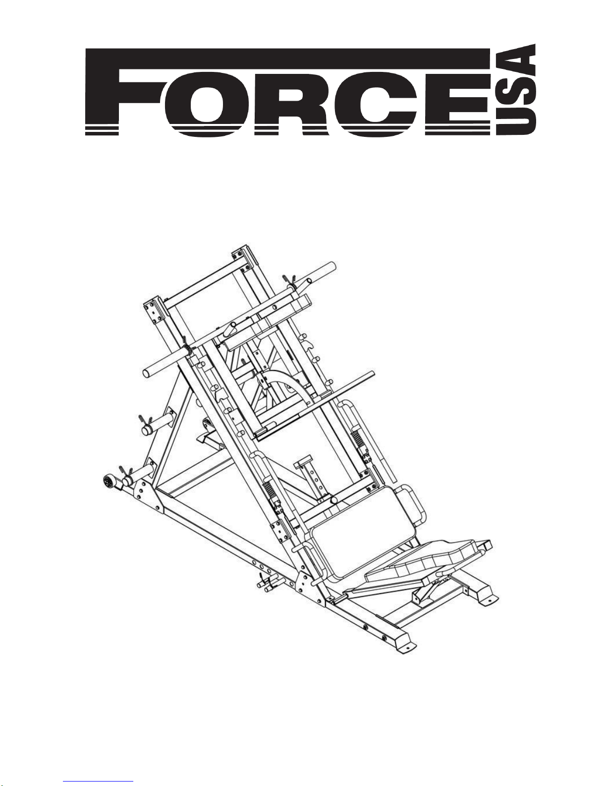
Force USA Ultimate 45⁰ Leg Press/
Hack Squat Combo
CAUTION!
Read all precautions and instructions in this manual before using this equipment.

ASSEMBLY MANUAL
Force USA Ultimate 45 Degree Leg Press/
Hack Squat Combo F-ULPHS
BEFORE YOU START
Remove all parts from the packaging and separate and count each various component to ensure
everything has been correctly provided.
Follow the instructions and consult both the individual assembly pages and the overall expanded views
of the equipment.
It is the owner’s responsibility to ensure that all users of this unit have read the owner’s manual and are
familiar with the safety precautions.
SAFETY PRECAUTIONS
● Highly recommended for two or more people to assemble the equipment to avoid injury.
● Assemble the equipment on a flat level surface.
● Consider placing a mat under the equipment to protect your floor.
● Wear appropriate footwear and clothing during assembly and use.
● Only tighten nuts and bolts by hand until the whole equipment is assembled.
● Ensure you correctly orientate each piece before attaching.
● Do not allow children and pets to be unsupervised around the assembly or usage of this
equipment.
● Ensure all parts are in full working order before use.
● Only one person should use the machine at any one time.
● Do not use the equipment outdoors or around water.
● Keep hair, fingers or clothing away from moving parts.
● Only use attachments recommended by the manufacturer.
● Never operate if any parts are not functioning correctly.
● Always correctly stretch and warm up before using the equipment.
● Stop immediately if you experience any pain, dizziness or nausea. See a doctor at once.
PLEASE NOTE: Descriptions of pieces as LEFT and RIGHT are from the point of view of standing behind the
equipment facing towards the front.
BEFORE STARTING ANY EXERCISE PROGRAM, CONSULT YOUR DOCTOR. ESPECIALLY IF YOU ARE
OVER THE AGE OF 35 OR HAVE PRE-EXISTING HEALTH PROBLEMS.
READ ALL INSTRUCTIONS BEFORE ASSEMBLING OR USING ANY FITNESS EQUIPMENT.
FORCE USA FITNESS EQUIPMENT ASSUMES NO RESPONSIBILITY FOR PERSONAL INJURY OR
PROPERTY DAMAGE SUSTAINED BY OR THROUGH THE USE OF THIS PRODUCT.
SAVE THESE INSTRUCTIONS.

PARTS LIST
NOTE: SOME PARTS MAY COME PRE ASSEMBLED, IN WHICH CASE CONTINUE ONTO THE
NEXT REQUIRED STEP OF ASSEMBLY
KEY NO.
PART DESCRIPTION F-ULPHS
SPEC
QTY
1
Left Stabilizer
1
2
Right Stabilizer
1
3
Front Connecting Frame
1
4
Rear Connecting Frame
1
5
Support Frame
2
6
Frame 2
7
Lower Crossmember
1
8
Upper Crossmember
1
9
Guide Rod
2
10
Sliding Frame
1
11
Upper Adjuster
1
12
Lower Adjuster
1
13
Shoulder Pad Mount
1
14
Lock Out
2
15
Adjuster-Outside
1
16
Adjuster-Inside
1
17
Lower Weight Carriage
1
18
Seat Frame
1
19
Upper Weight Carriage
1
20
Weights Post
4
21
Weights Slow Bracket
4
22
Lock Out Left
1
23
Lock Out Right
1
24
Backrest Pad Mount
1
25
Barbell Sleeve
2
26
Barbell Rod
Φ25×450
1
27
Axle
Φ16×M10×156
4
28
Safety Support
1
29
Bracket
240×158×5
4
30
Bracket
120×50×3
4
21
Bracket
120×101×4
4
32
Bracket
120×70×3
4
33
Moving Lock Pin
2
34
Backrest Pad
800×360×70
1
35
Seat Pad
660×340×70
1
36
Shoulder Pad
360×120×70
2
37
Rollers 8
38
Roller Wheel
Φ76×35 2 39
End Cap
□50
2
40
End Cap
□45 6 41
End Cap
Φ25
18
42
End Cap
□50×100 2 43
End Cap
Φ48
8

44
End Cap
□70×50 1 45
Sliding Sleeve
□60×□50
2
46
Bumper
100×50×25
1
47
Lock Pin
Φ16 1 48
Spring
Φ43×φ27×Φ8×80
2
49
Grip
Φ23×150
2
50
Hexagon Socket Button Head Screws
M8×25 2 51
Allen Screw
M8×8 2 52
Allen Bolt
M8×16 8 53
Allen Bolt
M8×25 1 54
Allen Bolt
M10×25 2 55
Hex Bolt
M12×25 4 56
Hex Bolt
M12×110
8
57
Hex Bolt
M10×125
4
58
Hex Bolt
M10×120
8
59
Hex Bolt
M10×115
2
60
Hex Bolt
M10×70
40
61
Hex Bolt
M10×90 2 62
Hex Bolt
M10×95 2 63
Hex Bolt
M10×20
12
64
Hex Bolt
M8×60 4 65
Hex Bolt
M8×65 4 66
Socket Countersunk Head Screw
M8×20 4 67
Carriage Bolts
M10×70 2 68
Aircraft Nut
M12 8 69
Aircraft Nut
M10
60
70
Washer
12
20
71
Washer
10
118
72
Washer
8
16
73
Washer
16 2 74
Large Washer
Φ10×Φ30×2
10
75
Spring Clip
Φ49 8 76
Spring Clip
Φ24.5 4 77
Spacer
Φ16
2
Allen Wrench
8#
1
Allen Wrench
5#
1
Allen Wrench
4#
1
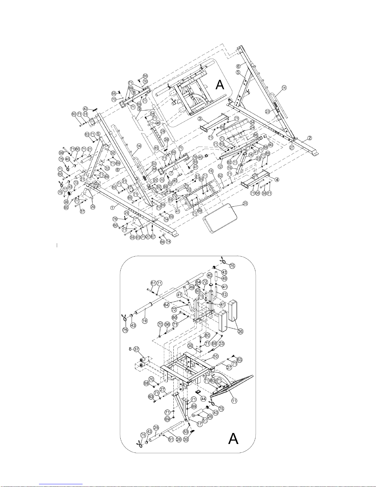
EXPLODED DIAGRAM
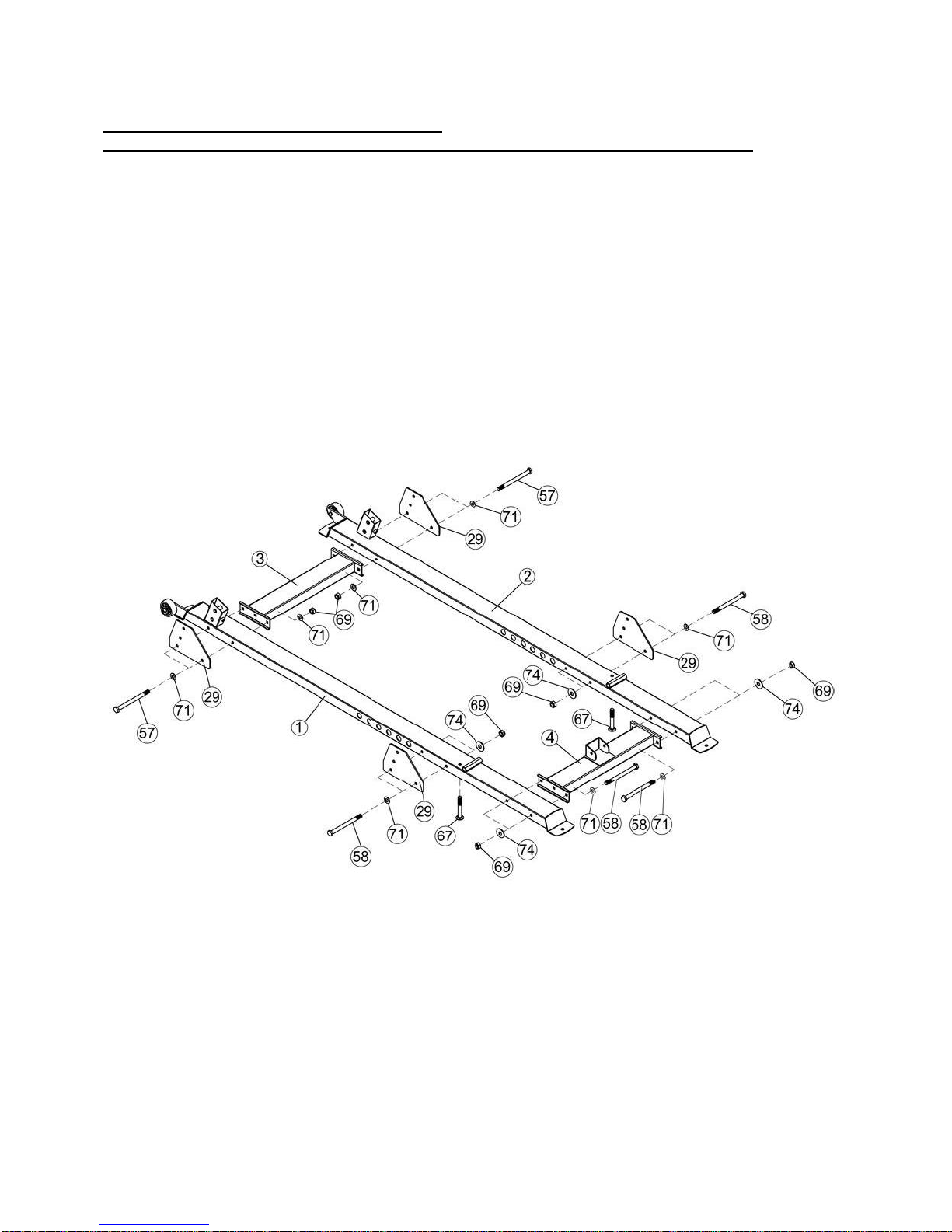
ASSEMBLY DIAGRAM 1
USE A PARTNER TO HELP WITH THIS STEP
REMEMBER: Only hand tighten all nuts and bolts until whole F-ULPHS is assembled.
1. Ensuring correct orientation, attach the Front Connecting Frame (Key #3) to the Left Stabilizer
(Key #1) and Right Stabilizer (Key #2) using 240×158×5 Bracket (Key #29), M10×125 Hex Bolt
(Key #57), Washer 10 (Key #71), and M10 Aircraft Nut (Key #69).
2. Attach the Rear Connecting Frame (Key #4) to the same Left Stabilizer (Key #1) and Right
Stabilizer (Key #2) using M10×120 Hex Bolt, Washer 10 (Key #71), Larger Washer (Key #74),
and M10 Aircraft Nut (Key #69).
3. Attach two 240×158×5 Bracket (Key #29) to the Left Stabilizer (Key #1) and Right Stabilizer (Key
#2) using M10×120 Hex Bolt (Key #58), Washer 10 (Key #71), Larger Washer (Key #74), and
M10 Aircraft Nut (Key #69).
4. Insert M10×70 Carriage Bolts (Key #67) to the Left Stabilizer (Key #1) and Right Stabilizer (Key
#2) [Continue in Diagram 2].
 Loading...