

Force USA F-G3-BASE Owner's Manual
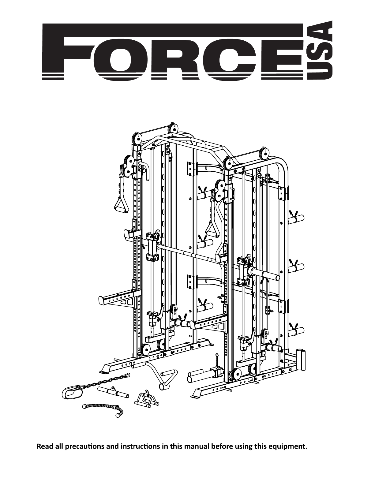
OWNER’S MANUAL F-G3-BASE
CAUTION!

ASSEMBLY MANUAL
BEFORE YOU START
Remove all parts from the packaging and separate and count each various component to ensure
everything has been correctly provided.
Follow the instructions and consult both the individual assembly pages and the overall expanded views
of the equipment.
It is the owner’s responsibility to ensure that all users of this unit have read the owner’s manual and are
familiar with the safety precautions.
SAFETY PRECAUTIONS
equipment.
Stop immediately if you experience any pain, dizziness or nausea. See a doctor at once.
PLEASE NOTE: Descriptions of pieces as LEFT and RIGHT are from the point of view of standing behind the
equipment facing towards the front.
BEFORE STARTING ANY EXERCISE PROGRAM, CONSULT YOUR DOCTOR. ESPECIALLY IF YOU ARE
OVER THE AGE OF 35 OR HAVE PRE-EXISTING HEALTH PROBLEMS.
READ ALL INSTRUCTIONS BEFORE ASSEMBLING OR USING ANY FITNESS EQUIPMENT.
FORCE USA FITNESS EQUIPMENT ASSUMES NO RESPONSIBILITY FOR PERSONAL INJURY OR
PROPERTY DAMAGE SUSTAINED BY OR THROUGH THE USE OF THIS PRODUCT.
SAVE THESE INSTRUCTIONS.
1
IMPORTANT ASSEMBLY INFORMATION
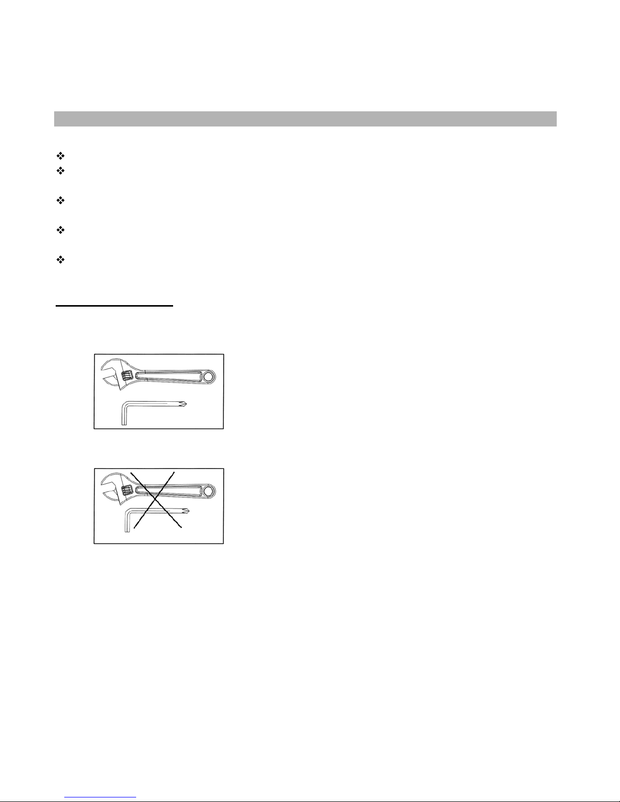
Tools Required for Assembling the Bench: Adjustable Wrench and Allen Wrench.
NOTE: It is strongly recommended that this equipment is assembled by two or more
people to avoid possible injury.
Ensure Carriage Bolts are inserted through the SQUARE holes on components that need to
be assembled. Attach washer only to end of the Carriage Bolt.
Use Allen Bolts or Hex Bolts inserted through the ROUND hole on components that need to
be assembled.
Always wait until all bolts are assembled onto the bench before tightening the bolts. Do not
tighten each bolt right after it is installed
Fasten Nuts and Bolts
Securely tighten all Nuts and Bolts after all
components have been assembled in current and
previous steps.
NOTE: Do not over tighten any component with
pivoting function.
Make sure all pivoting components are able to move
freely.
Do not tighten all Nuts and Bolts in this step.
2

KEY NO. PART DESCRIPTION SPEC QTY
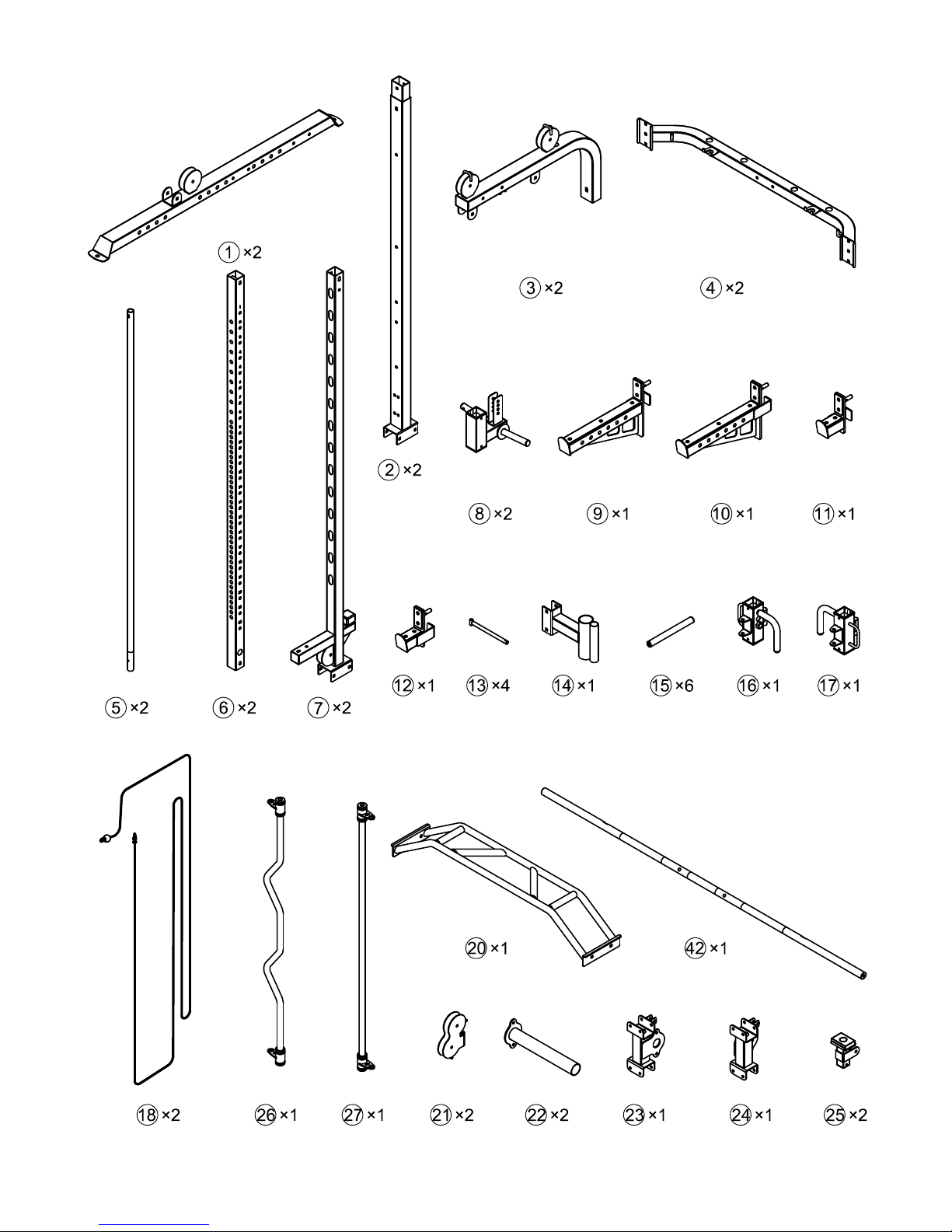
1 Base Frame 2
2 Rear Post 2
3 Top Frame 2
4 Connecting Frame Rear 2
5 Guide Rod Rear φ25×1792 2
6 Front Guide Shaft 2
7 Intermediate Stand 2
8 Plate Loader 2
9
Long Safety Rack L
1
10
Long Safety Rack R
1
11
Short Safety Rack L
1
12
Short Safety Rack R
1
13 Weights Post 4
14 Barbell Socket 1
15 Weights Stow Rod φ25×245 6
16
Frame Slider L
1
17
Frame Slider R
1
18 Double pull cable L=8100mm 2
19
Rack Liner 415×45×5 2
20 Horizontal bar 1
21 Pulley Case 2
22 Weights Stow Rod 2
23
Roller Rack L 1
24 Roller Rack R 1
25 Safety hook Bracket 2
26
Cambered Bar (attachment)
1
27
Straight Bar (attachment)
1
28
Hub
4
29 Bar End φ38×φ9×8 4
30 Rotating Shaft 1
31
Rotating Frame
1
32
Handle
1
PARTS LIST
NOTE: SOME PARTS MAY COME PRE ASSEMBLED, IN WHICH CASE CONTINUE ONTO
THE NEXT REQUIRED STEP OF ASSEMBLY
3

33
Spacer
1
34 Pop pin 1
35 Small grip frame 1
36 Moving Lock Pin 2
37 V-type handle 1
38 Pulley Bracket 2
39 Hanging Bar L 1
40 Hanging Bar R 1
41 Semicircle Fixed Seat R15×R30×22 2
42 Weight Rod φ30×1845 1
43 Roller set 8
44 Nylon Strap Iso-Handle HERS 2
45 15-Joint Chain 1
46 Hook φ8 4
47
Ankle Strap
PH1300 1
48
Rope
1
49 Pulley with Bearings φ96 12
50 Small Pulley with Bearing φ75×25 4
51 Olympic Barbell Sleeve φ50×210 6
52 Olympic Barbell Sleeve φ50×150 4
53 Spring Clip φ49 12
54 Spring Clip φ24.5 10
55 Bracket 120×71×13×3 4
56 Safety Hook R25×φ11×6 2
57 Spacer φ16×φ11×16 4
58 Bushing φ38×φ34×φ27×26 10
59 Rack Liner 90×45×5 6
60 Small handle tube
φ25×1.5×400
1
61 Dips Handle Φ23×150 4
62 Dips Handle φ24×φ18×227 2
63 Rubber Stopper Φ78×Φ50×39 2
64 Rubber Stopper 80×56×20 2
65 Safety hook Bracket Guides 38×26×30×3 2
66 Slide Guide
□
60×2.5×□50×25
8
67 Rectangular End Cap
□
70×50
2
68 Rectangular End Cap
□
45
2
69 Rectangular End Cap
□
50
2
4

70 Rectangular End Cap
□
38
2
71 Tube End Cap
□
38
2
72 Rectangular End Cap φ48 2
73 Rectangular End Cap φ25 18
74 Bushing φ38×φ34×φ25×22 2
75 Bushing φ25×φ21.8×φ12.2×8 6
76 Hex Bolt M12×90 3
77 Hex Bolt M10×90 12
78 Hex Bolt M10×85 8
79 Hex Bolt M10×25 10
80 Hex Bolt M10×65 2
81 Hex Bolt M10×75 10
82 Hex Bolt M10×70 10
83 Hex Bolt M10×45 16
84 Hex Bolt M8×45 2
85 Allen Bolt M10×25 2
86 Allen Bolt M8×25 4
87 Sunk Screw M6×12 18
88 Hexagon socket button head screws M8×20 4
89 Washer φ30×φ10.5×2.5 4
90 Washer φ38×φ13×3 4
91 Washer 8 8
92 Washer 10 124
93 Washer 12 6
94 Nut M8 2
95 Nut M10 60
96 Nut M12 3
Allen wrench 6# 1
Allen wrench 5# 1
Allen wrench 4# 1
5
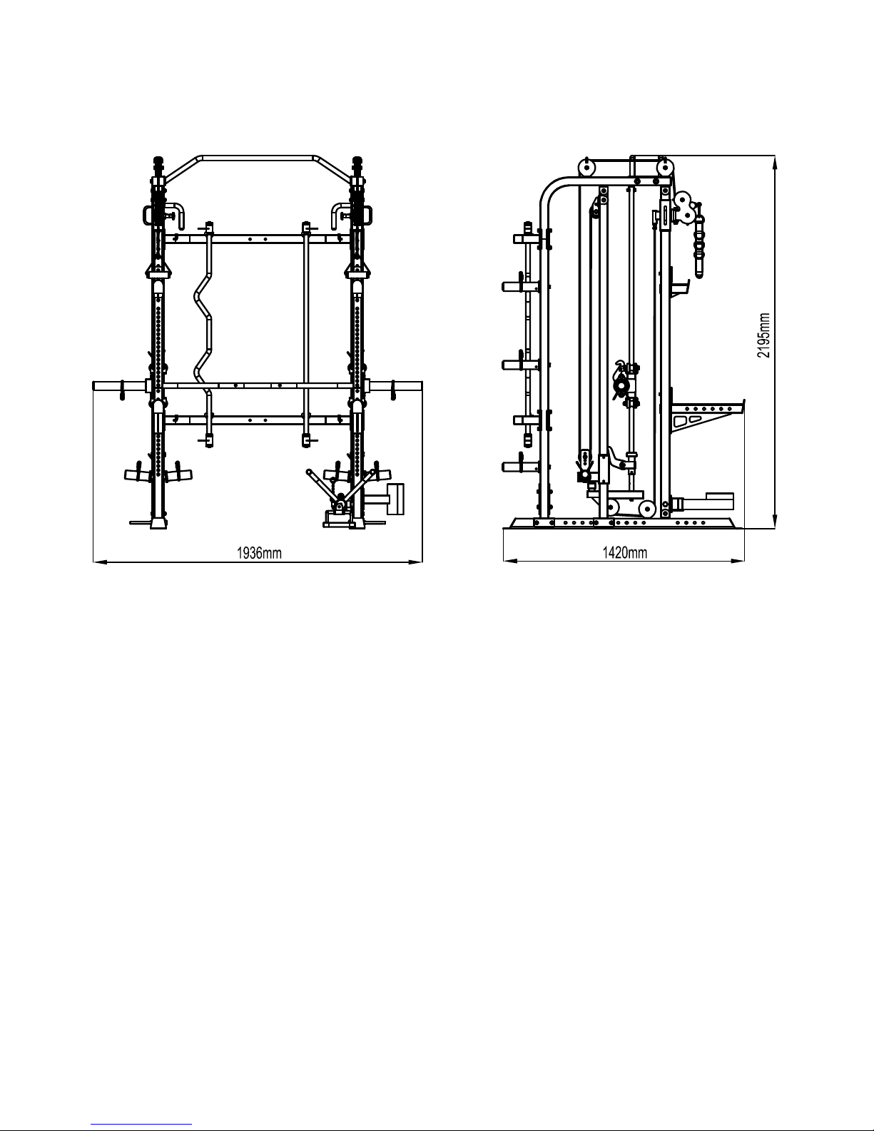
Assembled Dimension: 1936mm x 1420mm x2195mm
6
7
 Loading...