

Page 1
REF5-BB
Undercounter Blood Bank Refrigerator
Order parts online
www.follettice.com
Installation, Operation and Service Manual
Serial numbers C45184 and above
Following installation, please forward this manual
to the appropriate operations person.
801 Church Lane • Easton, PA 18040, USA
Toll free (800) 523-9361 • (610) 252-7301
Fax (610) 250-0696 • www.follettice.com
00193466R00
Page 2

Welcome to Follett
Follett equipment enjoys a well-deserved reputation for excellent performance, long-term reliability and
outstanding after-the-sale support. To ensure that this product delivers that same degree of service, we ask that
you take a moment to review this manual before beginning the installation. Should you have any questions or
require technical help at any point, please call our technical service group at (800) 523-9361 or (610) 252-7301.
Before you begin
After uncrating and removing all packing material, inspect the equipment for concealed shipping damage. If
damage is found, notify the shipper immediately and contact Follett Corporation so that we can help in the ling
of a claim, if necessary.
Speci cations
REF5-BB
34" height for freestanding use or installation below standard 36" (915mm) high counter
2 drawer – up to 50 (450ml) bags
Maximum drawer load - 35 lbs (16kg) each
Electrical speci cations
115V, 60Hz, 1 phase
Full load amps: 8.0
Minimum circuit ampacity: 15 amp
Maximum size of branch circuit overcurrent device: 15 amp
Refrigeration speci cations
Refrigerant – R404A
Charge size – 10 oz
Maximum design pressures:
High side – 422psi
Low side – 175psi
Installation speci cations
Ambient temperature must not exceed 100 F (38 C).
The front louvered panel must be kept free of any cabinet trim or obstructions to ensure proper ventilation of the
refrigeration system.
Important cautions
• Equipment must be wired according to local and NEC codes.
• Always disconnect power before servicing refrigerator.
2
Page 3
Installation
Fig. 1
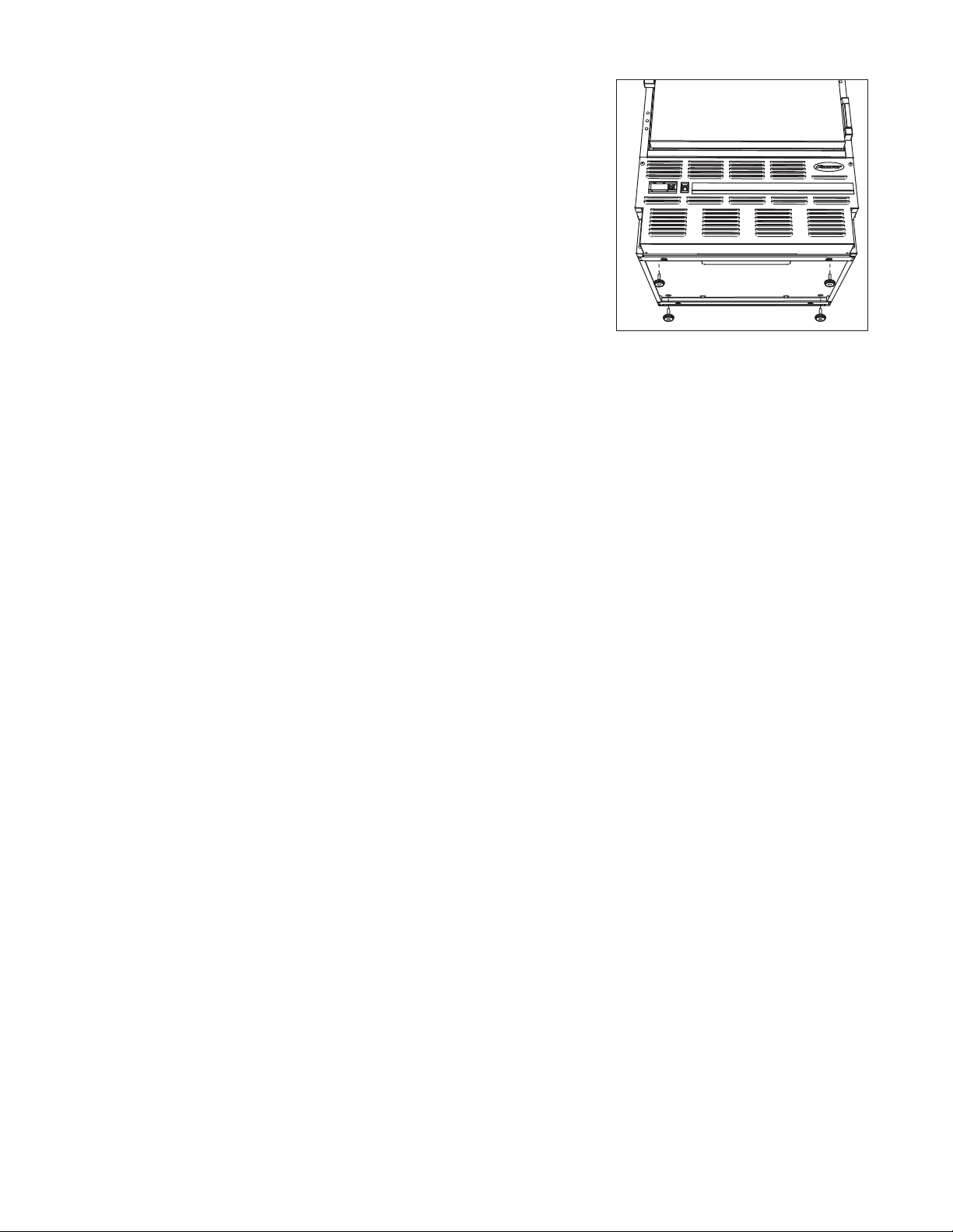
Installing legs – required
1. Remove legs from plastic bag packed inside refrigerator.
2. Tip refrigerator back and screw legs in all the way to stop (they will
extend 1/8" below base of refrigerator).
3. Adjust legs as needed to level refrigerator in both directions. To access
legs, remove the lower front panel. Turn legs clockwise to extend legs.
Chart recorder/alarm module
The chart recorder/alarm module (when ordered) is packed in the lower drawer.
Temperature surveillance module
Follett’s all-in-one temperature alarm and chart recorder module (manufactured for Follett by Dickson) may be
included with your FZR5-PL. Please refer to the Dickson instructions packed with this module for set-up and
operation instructions.
Follett’s monitoring bottle and temperature probe has already been installed in the Follett FZR5-PL. Simply
connect the loose end of the probe wire on the back of the unit to the surveillance module to complete the install.
A box of sixty (60) -50 to +50 7-day charts have also been included with this module. Replacement charts and
pens can be ordered from Follett by calling Technical Service at 800-523-9361:
Item # 00162099 — Box of sixty (60), -50 to +50, 7-day replacement charts
Item # 00162081 — Box of six (6) replacement red pens
Charts with different temperature scales are also available. Contact Dickson at www.dicksondata.com
3
Page 4
Reversing the door swing – optional
1
2
1
1
2
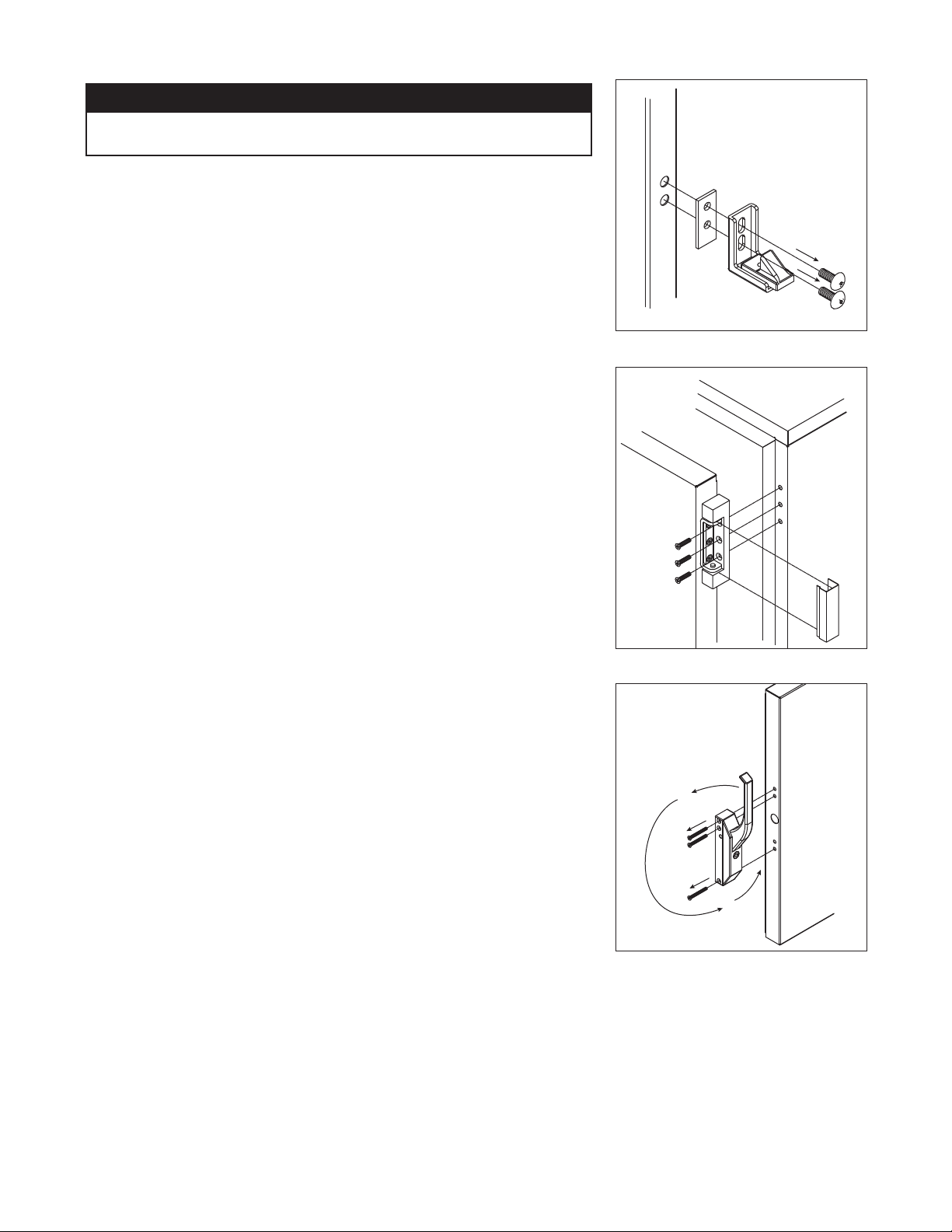
NOTICE
When reinstalling latch and hinge screws, 242 blue Loctite* MUST be
applied to screws. Torque screws to 25 in-lbs.
1. Remove screws and latch from refrigerator cabinet (Fig. 2.1).
2. Use at screwdriver to carefully remove (do not scratch) hinge
covers (Fig. 3.1).
3. Support door and remove screws attaching hinge to refrigerator
cabinet (Fig. 3.2).
4. Cover hinge screw holes with screw hole plugs removed from
opposite side.
5. Reverse door. Apply 242 blue Loctite to hinge screws and reinstall
torqued to 25 in-lbs.
6. Reinstall latch on opposite side.
7. Remove screws and handle from door (Fig. 4.1).
8. Rotate handle (Fig. 4.2).
9. Apply 242 blue Loctite to latch screws and reinstall torqued to 25 in-lbs.
Note: See keypad lock manual for reversing a door that is equipped with a
keypad lock.
Fig. 2
1
Fig. 3
Fig. 4
* Loctite is a registered trademark of Henkel Corporation in the United States and other countries.
4
Page 5
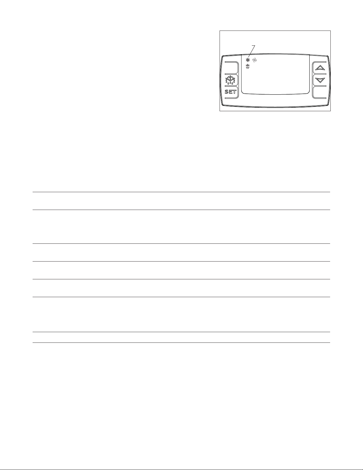
Controller operation
In normal operation the controller displays cabinet temperatures
in degrees C (default) or user-selected degrees F. Degrees C
temperatures are displayed to 1 decimal point.
The controller is pre-programmed with a +3.5 C (+38 F) set point
which provides a compressor cut-in at +3.5 C (+38 F) and cut-out at
+5.0 C (+41 F).
All set points have a 1.5 C differential. The 1.5 C differential means
that with a +3.5 C set point, for example, the compressor will turn off
at +3.5 C (+38 F) and turn on when the cabinet temperature reaches
+5 C (+41 F).
This temperature may not re ect the temperature of the blood
products in the refrigerator. The temperature of the blood products will be re ected on the recorder chart and the
recorder's digital temperature display. At times there may be a difference between the two displayed temperatures.
Adjust the controller SET value to achieve your desired blood product temperature as displayed on your chart
recorder.
Fig. 5
refrigeration
system
energized
°C
2.5
To display temperature cut-out
STEP INPUT DISPLAY
1 Press and release SET Current cut-out temperature will display for approximately 5 seconds.
Display will return to current refrigerator temperature.
To change temperature cut-out
STEP INPUT DISPLAY
1 Press and hold SET for Current cut-out temperature displayed and °C will ash
3 seconds
2 Press UP or DOWN arrows to New cut-out temperature displayed
desired cut-out temperature
3 Press and release SET New cut-out temperature blinks three times, then current refrigerator
temperature will display
Refer to the chart below for the set point for your application's required temperature range.
SET POINT DEGREES C CUT-IN DEGREES C CUT-OUT DEGREES C NORMAL DISPLAY RANGE DEGREES C
+3.5 C +5.0 C +3.5 C 1.5 to 5.0 C
5
Page 6

Controller security
The controller panel can be locked to prevent inadvertent or intentional programming changes. In locked mode,
the controller will display cabinet temperature and cut-out set point only.
To lock the controller
1. Press the UP and DOWN ARROW buttons together for 3 seconds until “PoF” displays (will ash 3 times).
2. Programmer is now locked.
To unlock the controller
1. Press UP and DOWN ARROW buttons together for 3 seconds until “Pon” displays (will ash 3 times).
2. Programmer is now unlocked.
Controller programmer key (optional accessory)
A controller programming key is available from Follett to provide fast and easy re-programming of factory settings.
Programming key part number is 00183335.
Programming refrigerator from the programming
Fig. 6
key (download)
1. TURN OFF refrigerator.
2. Remove 6 screws from front panel to access back of
controller.
3. Insert programming key into 5 PIN receptacle
on controller back.
4. TURN ON refrigerator.
5. Values from key automatically download to refrigerator
(“dol” message blinks followed by “end”).
Line
4
Comp
6 75
Supply
•
8
Controller
programming key
(accessory)
6. After 10 seconds display returns to current refrigerator
temperature and controller will restart with new values.
7. TURN OFF.
8. Remove key.
9. Reinstall panel.
Note: An “Err” message displays for failed programming. Turn refrigerator OFF then ON to restart download, or
remove key to abort.
Probe
12
11
!
••••
6
Page 7

Operation
1
2
The temperature controller and probe indicate when the refrigeration system is required to turn on and off.
The refrigeration system removes heat from the cabinet interior and rejects it to the surrounding room air. When the
cabinet interior temperature reaches +1.5 C above the controller set point, the probe signals the controller to turn
the refrigeration system on. The normally open controller contacts close and energize the condenser fan motor and
compressor. The compressor uses a current-style starting relay and a starting capacitor to start the compressor
motor.
When the cabinet interior temperature falls to the set point, the probe signals the controller to turn the refrigeration
system off. The controller contacts reopen, which de-energizes the condenser fan motor and the compressor. The
evaporator fan motor runs continuously.
Any accumulated frost on the evaporator coils melts during the off cycle. The condensate drains to a drain pan
mounted alongside the condensing unit. The heat from the condensing unit evaporates any condensate in the
drain pan.
Temperature control
The temperature control system is preset by the factory to maintain a cabinet temperature of +3.5 C to +5 C
(+38 F to +41 F). If desired, the cut-out temperature can be raised as high as +6°C by following the instructions
on page 5 for changing the temperature set point. The +1.5 C cut-out differential will be maintained regardless of
the controller set point.
Defrosting
REF5-BB Series undercounter refrigerators do not require manual defrosting. The unit cooler defrosts automatically
when the condensing unit is in the OFF cycle.
Cleaning
Use only non-chlorine-based cleaners. Cleaners containing chlorine can cause staining and pitting of the
!
stainless steel.
Interior – Using a sponge or soft cloth, clean unit with a non-abrasive, non-chlorinated, all-purpose detergent.
Exterior – Wipe exterior with a soft cloth in the direction of grain as needed. Stainless steel polish may be used to
enhance the nish of the unit.
Annual cleaning
Removal of dust and other particulates from air intake areas and the condenser is important for proper operation.
Some environments with large amounts of dust may require more frequent cleaning.
1. Disconnect power to unit by turning switch on the lower front
panel to the OFF position, switching circuit breaker to OFF
position, and removing power cord from receptacle.
2. Remove lower front panel (Fig. 7.1).
Note: Front louvered panel may be completely removed for
easier cleaning by disconnecting the controller wiring plugs from
the freezer.
3. Remove drain pan (Fig. 7.2).
4. Clean drain pan with a non-abrasive, non-chlorinated all-purpose
detergent.
5. Reinstall drain pan.
6. Use a vacuum cleaner with brush attachment to clean condenser
through lower front panel and compressor motor and related
parts through lower rear panel.
7. Reinstall lower front panel.
7
Fig. 7
Page 8

Service
1
2
2
0
8
2
6
4
P
r
o
d
u
c
t
M
o
d
u
l
e
N
o
.
S
e
r
v
i
c
e
N
o
.
Easton Pennsylvania
MOTOR COMPRESSOR T
HER
MALL
Y PRO
TECTED
DESIGN PRE
SSURE HIG
H SIDE
MIN. B
RANCH CIRC
UIT AMP
ACITY
MAX. B
RANCH
C
I
R
CUIT FUS
E SIZE
SIN
GLE
PHASE
LOW SIDE
L
THE
US
A
MADE IN
O
Z
P
S
I
G
R
C
N
S
F
U
L
PART NO
HZ
CHARGE
A
M
P
S
R
A
M
P
S
U
VOLTS
CORPORATION
SERIAL NO
MODEL
FULL LOAD AMPS
REF
RIGERANT
1
2
3
Latch adjustment
To adjust for proper latch engagement
1. Loosen striker plate mounting screws (Fig. 8.1).
2. Move striker plate up or down as required and tighten screws.
3. Test operation of latch.
To adjust for proper gasket seal
1. Loosen striker depth adjustment screw (Fig. 8.2).
2. Adjust stop in or out and tighten screws.
3. Test operation of latch.
Door gasket replacement
1. Remove existing gasket from mounting track.
2. Verify mounting track is free of any remaining gasket material.
3. Align new gasket with mounting track and press rmly in place.
4. Open and close door, checking for proper gasket seal without
pinching against refrigerator.
5. Adjust latch and or striker as necessary for proper door closure.
Fig. 8
Fig. 9
Slide-out compressor tray
Follett’s slide-out compressor tray allows technicians to partially
slide the condensing unit from the refrigerator back without cutting
refrigerant lines.
1. Remove rear panel (Fig. 9.1).
2. Remove two bolts securing condensing unit to refrigerator base
(Fig. 9.2).
3. Gently slide condensing unit out (Fig. 9.3).
Note: Do not put undue strain on the refrigerant lines.
Removing drawers
1. Pull drawer forward to stop.
2. Lift drawer front to free front rollers from sides.
3. Still lifted, pull drawer forward to free back rollers from sides.
Removing slides
1. Push slides all the way back.
2. Swing bottom of slide away from refrigerator wall and lift slide off of rollers.
8
Page 9

Controller replacement
RELAY
START
FAN
EVAP.
CONTROLLER
TEMPERATURE
120 VAC
M
COND.
FAN
BLK
LOAD
C
R
S
S
COMP
OVER
CONDENSING UNIT
L1
2
WHT
1
START
CAP.
WHT
WHT
L2
BLK BLK
BLU
WHT
BLU
3.5
7
8
5
4
1. Disconnect power to unit.
a. Push front panel rocker switch to OFF position.
b. Disconnect power cord.
2. Remove 6 screws from front panel and slide panel forward to access back of controller.
3. Disconnect front panel and wiring harness from refrigerator at the 3, and 4 pin connectors to simplify
replacement.
4. Push in on center of side brackets (on controller) to release and slide brackets back and off controller.
5. Push controller and wires out through front of front panel.
6. Using wiring schematic (attached to front panel and below) as a guide, remove wires one at a time from back
of existing controller and connect to corresponding terminals on replacement controller.
7. Insert replacement controller back through front of panel.
8. Slide brackets onto sides of controller and push against back of front panel.
9. Reconnect 3 and 4 pin connectors of wiring harness to refrigerator.
10. Keeping wiring clear of condenser, replace front panel.
11. Restore power and test operation. Reprogram replacement controller if necessary.
Wiring diagram
9
Page 10

Refrigeration system
The REF5-BB series refrigeration system is designed to give many years of trouble-free service. Except for
routine cleaning of the air-cooled condenser and related parts, the refrigeration system requires no service
or maintenance. The system uses a thermostatic expansion valve and is critically charged. Access ttings are
provided for ease of service. However, the connection of refrigeration service hoses to the ttings will almost
invariably result in a signi cant change in the system charge. This change can adversely affect the performance
of your refrigerator. Therefore, Follett recommends that if hoses are ever connected to the refrigeration system
for service, the refrigerant should be recovered, the system evacuated, and recharged by weighing in the correct
refrigerant charge.
Note: Do not charge the system by pressures.
Checking refrigeration system pressures
1. Remove the rear access panel (Fig. 9).
2. Turn the power switch to the on position.
3. Following the instructions on page 5 verify that the temperature controller is set to the original factory set point
(cut-out) setting of +3.5 C (+38 F).
4. Allow the refrigerator to operate and stabilize at least 30 minutes, verifying the cut-out temperature is
being reached.
5. Connect refrigerant hoses to access ttings and measure air temperature at condenser intake grille.
6. Verify correct pressures with the temperature chart below.
7. Troubleshoot refrigeration system as needed.
Condenser inlet air temperature 70 – 100 F
Discharge pressure (psi) 190 – 210
Suction pressure (psi) 40 – 50
Note: Do not attempt to obtain correct refrigeration pressures by adjusting the system charge.
Refrigeration system diagram
COMPRESSOR
10oz. Charge
Low Psi
Vapor
EVAPORATOR FAN
EVAPORATOR
LOW SI DE
SERVICE PORT
HIGH SIDE
SERVICE PORT
High Psi
Vapor
FA N
Low Psi
Liquid
EVAPORATOR/DEFROST UNIT
HIGH PRESSURE VAPOR LOW PRESSURE VAPORHIGH PRESSURE LIQUID LOW PRESSURE LIQUID
TXV
HEAT EXCHANGE
10
DRYER
High Psi
Liquid
CONDENSING UNIT
Page 11

Blood bank refrigerator troubleshooting guide
Before calling for service
1. Check that unit is plugged in.
2. Test outlet with another appliance to verify power.
Symptom
Refrigerator does not operate
(no components run).
Compressor does not run.
Evaporator fan motor does not run.
Refrigerator does not shut off.
Refrigerator does not maintain
temperature (all components run).
Possible cause
1. Power switch faulty or in OFF
position; loose connection.
2. Refrigerator not plugged in.
3. No power to cord.
4. Temp controller not energizing
components.
5. Probe not sensing cut in
temperature.
1. Thermal overload open or
defective.
2. Capacitor and/or relay defective.
3. Compressor defective.
1. Defective fan motor.
1. Controller not sensing cut off
temperature.
2. Controller keeping refrigeration
system energized.
1. Condenser or evaporator coil
needs cleaning.
2. Faulty door gasket or hinges/latch
loose
3. Excessively high ambient.
4. Refrigerant leak.
5. Incorrect refrigerant charge.
6. Plugged or defective expansion
valve.
7. Inefficient compressor.
Solution
1. Turn power switch to ON position;
check switch and connections.
2. Connect plug.
3. Restore power.
4. Check controller contact terminals for
power. Replace controller if needed.
5. Replace controller and/or probe.
1. Allow to cool or replace.
2. Replace as required.
3. Replace compressor.
1. Replace fan motor.
1. Replace controller and/or probe.
2. Replace controller.
1. Clean coils as needed.
2. Replace door gasket.
3. Maximum recommended ambient is
100 degrees F.
4. Locate and repair leak.
5. Recover, evacuate and weigh in
correct charge.
6. Replace expansion valve.
7. Consult technical service.
If problems persist after following this basic troubleshooting guide, call Follett’s
technical service group at (800) 523-9361 or (610) 252-7301.
11
Page 12

Replacement parts
5
1
2
10
9
4
3
8
7
6
Evaporator
Reference # Description Part #
1 Cover, evaporator, (includes 00152892) 00155564
2 Fan guard 00152892
3 Fan blade 00152991
4 Bracket, fan motor 00152983
5 Fan motor, evaporator 00104919
6 Air baffle 00165126
7 Drain pan, evaporator 00162511
8 Evaporator 00151563
9 Expansion valve (includes 00106534) 00165118
10 Insulation, bulb 00106534
12
Page 13

3
2
4
7
1
8
5
6
Condensing Unit
Reference # Description Part #
Condensing unit 00105106
1 Condenser 00105619
2 Shroud, condenser 00157347
3 Condenser fan blade 00105007
4 Condenser fan motor 00104992
5 Fan motor bracket 00157412
6 Compressor 00104950
7 Starting capacitor 00104968
8 Filter drier 502724
Not shown Cap, starting capacitor 00105627
Not shown Starting relay 00104976
Not shown Overload protector 00104984
13
Page 14

14
13
12
1
3
11
10
8
15
2
4
5
Hardware
Reference # Description Part #
1 Latch & striker includes screws 00105023
2 Latch screws, 3 per latch 00103507
3 Door, REF5-BB (includes gasket - 21 3/8" x 21 3/8") 00105015
4 Hinge, each - 2 required, includes screws 00105031
5 Hinge screws, each - 6 per hinge 00105080
6 Gasket, REF5-BB 00125732
7 Strip sealer (set of 4) REF5-BB 00130138
8 Drawer (includes 8 and 4 each of 10, 11 & 15) 00165134
9 Drawer slides (pair) 00161927
10 Nut, acorn, each (4 required per drawer) 00161802
11 Screw, 5/8", each (4 required per drawer) 200093
12 Screw, 7/8", each (4 required per drawer) 00161794
13 Washer, each (4 required per drawer) 00161786
Kit Drawer & slide mounting hardware kit
(includes 8, 9, 4 each of 10, 11, 12, 13 and 8 each of 15) 00165142
14 Striker screws, each - 2 per striker 502287
15 Bearing, roller 00167726
Kit Slide & bearings (includes 9 (pair) and 4 each of 12, 13 & 15) 00167924
Kit Bearings & screws kit 00167957
(includes 8 each of 15 and 4 each of 10, 11, 12 & 13)
7
6
9
14
Page 15

Hardware & electrical components
4
1
2
3
5
6
Reference # Description Part #
1 Temperature controller 00900100
Not shown Temperature probe & harness 00165167
2 Power switch 00114371
3 Front panel (includes 00114371 and 00105379) 00165159
4 Front panel screws, each - 6 per panel 00105379
Not shown Rear panel, includes screws 00130161
Not shown Rear panel screws, each - 6 per panel 00105387
5 Condensate pan 00155622
6 Evaporator drain line, sold by the foot 203627
Not shown REF5-BB programming key, degrees C 00193367
Not shown Power cord 00103903
Chart recorder related items
Reference # Description Part #
Not shown Gasket, bottle 00112029
Not shown Bracket, bottle 00161463
Not shown Bottle 00112037
Not shown Battery 00112177
Not shown 6" replacement, 7 day charts (quantity of 60) 00162099
Not shown Replacement pens (quantity of 6) 00162081
Not shown Probe, chart recorder 00162073
15
Page 16

801 Church Lane • Easton, PA 18040, USA
Toll free (800) 523-9361 • (610) 252-7301
Fax (610) 250-0696 • www.follettice.com
00193466R00
04/08
 Loading...