

Page 1
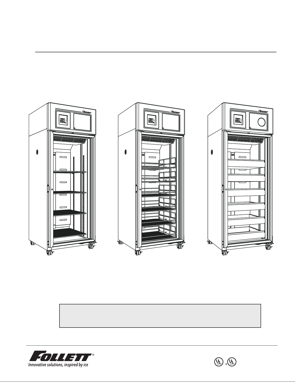
REF 20/25 – LB
REF 20/25 – PH
REF 20/25 – BB
Order parts online
www.follettice.com
Installation, Operation and Service Manual
Following installation, please forward this manual
totheappropriate operations person.
801 Church Lane • Easton, PA 18040, USA
Toll free (877) 612-5086 • +1 (610) 252-7301
www.follettice.com
00926170R09
Page 2

Contents
Welcome to Follett. . . . . . . . . . . . . . . . . . . . . 3
Before you begin ........................... 3
Ambients ................................. 4
Clearances ............................... 4
Electrical specications ..................... 4
Refrigeration specications .................. 4
Detail drawing ............................. 4
Installation ...........................5
Adjust self-closing door (if necessary) .......... 5
Install shelves (if equipped) and power up ....... 5
Fill product bottle. . . . . . . . . . . . . . . . . . . . . . . . . . . 6
Remote alarm connections (if desired) ......... 7
Dry contacts ........................... 7
RS-485 port ........................... 7
Operation ...........................8
Quick setup checklist ....................... 8
Interior LED lights .......................... 8
Set time & date ............................ 8
Change temperature display to show degrees
Fahrenheit (if desired) ....................... 9
High and low alarm setup ....................10
Alarms .................................. 12
Alarm muting ............................ 12
Alarm volume selection .................... 13
Alarm silence ............................ 13
Password PIN security (default is 3843) ....... 14
To turn password on/off .................... 14
To make a new password PIN ............... 15
Min/max temperature logging ................ 16
Probe calibration .......................... 17
Chart recorder set up (if so equipped) ......... 18
Chart recorder calibration ................... 18
Changing the chart paper ................... 18
Replacing the pen ......................... 18
Removing drawers ........................ 19
Removing slides .......................... 19
Cleaning ............................20
Interior cleaning .......................... 20
Exterior cleaning .......................... 20
Annual cleaning .......................... 21
Service .............................22
Refrigeration system ....................... 22
Defrosting .............................. 22
Controller operation ....................... 23
Temperature sensor readings ................ 23
Heated door (option) – changing cycle ........ 24
Controller hot key ......................... 27
Hot key upload ........................... 27
Hot key download ......................... 28
Troubleshooting .....................34
Before calling for service ................... 34
Appendix ...........................35
Control key functions ...................... 35
Menu Navigation table ..................... 35
Replacement parts ...................36
Unit cooler ............................... 36
Cabinet ................................. 37
Facade ................................. 38
Door assembly ........................... 39
2 00926170 – REF20/25 LB, PH, BB
Page 3
Welcome to Follett
Follett equipment enjoys a well-deserved reputation for excellent performance, long-term reliability and outstanding
after-the-sale support. To ensure that this product delivers that same degree of service, we ask that you take a
moment to review this manual before beginning the installation. Should you have any questions or require technical
help at any point, please call our technical service group at (877) 612-5086 or +1 (610) 252-7301.
Before you begin
After uncrating and removing all packing material, inspect the equipment for concealed shipping damage. If damage
is found, notify the shipper immediately and contact Follett Corporation so that we can help in the ling of a claim, if
necessary.
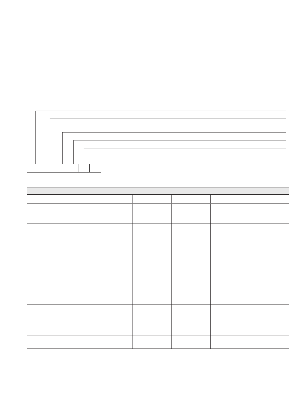
Check your paperwork to determine which conguration you have. Follett conguration numbers are designed to
provide information about the type of refrigerator you are receiving. Following is an explanation of the different item
numbers.
Model
Cubic foot capacity – 20, 25
Conguration – LB (Laboratory - shelves), PH (Pharmacy - baskets),
BB(Bloodbank - drawers)
Door hinge – R (Right hand), L (Left hand)
Door heater option – 00 (No door heater), HT (door heater)
Chart recorder option – 00 (No chart recorder), CR (Chart recorder)
REF 20 LB R 00 00
REF20-LB REF25-LB REF20-PH REF25-PH REF20-BB REF25-BB
Capacity
Storage
system
Exterior
width
Exterior
depth
Exterior
depth with
handles
Exterior
height with
casters
Interior
dimensions
(w x h x d)
Crated
weight
Max. heat
rejection
19.7 cu ft
(558L)
(4) epoxy-
coated shelves
29.75" (76 cm) 29.75" (76 cm) 29.75" (76 cm) 29.75" (76 cm) 29.75" (76 cm) 29.75" (76 cm)
29" (74 cm) 35" (89 cm) 29" (74 cm) 35" (89 cm) 29" (74 cm) 35" (89 cm)
30.5" (78 cm) 36.5" (93 cm) 30.5" (78 cm) 36.5" (93 cm) 30.5" (78 cm) 36.5" (93 cm)
79.5" (202 cm) 79.5" (202 cm) 79.5" (202 cm) 79.5" (202 cm) 79.5" (202 cm) 79.5" (202 cm)
24" x 22.5" x 56"
(61 cmx 58 cm x 143 cm)
395 (180 kg) 430 (196 kg) 450 (205 kg) 485 (220 kg) 475 (216 kg) 525 (239 kg)
950 BTU/hr 1050 BTU/hr 950 BTU/hr 1050 BTU/hr 950 BTU/hr 1050 BTU/hr
24.6 cu ft
(697L)
(4) epoxy-
coated shelves
24" x 28.5" x 56"
(61 cmx73 cm x 143 cm)
Specications
19.7 cu ft
(558L)
(6) epoxycoated baskets
24" x 22.5" x 56"
(61 cmx 58 cm x 143 cm)
24.6 cu ft
(697L)
(6) epoxycoated baskets
24" x 28.5" x 56"
(61 cmx 73 cm x 143 cm)
19.7 cu ft
(558L)/ 280
bags (450ml)
(6) stainless
steel drawers
24" x 22.5" x 56"
(61 cmx 58 cm x 143 cm)
24.6 cu ft
(697L)/ 360
bags (450ml)
(6) stainless
steel drawers
24" x 28.5" x 56"
(61 cmx 73 cm x 143 cm)
00926170 – REF20/25 LB, PH, BB Welcome to Follett 3
Page 4
Standard features – all models
Door Dual pane, low-E glass, condensation free to 80 F (27 C) air/60% RH
Door handle ADA-compliant, full length handle with integral lock
Interior/exteriormaterial Heavy-duty, corrosion resistant stainless steel
Casters (4) dual-wheel swiveling casters with toe locks
Insulation 2.75" (7 cm) thick, CFC-free foam insulation throughout
Lighting (2) full length side LED lights
Air circulation system Ducted air through 12 back plenum openings with front face return
Temperature probe Stainless steel RTD (resistance temperature detectors) top, bottom probe standard
on - BB models, available as option on -LB, -PH models, immersible with panel quick-
disconnect
Ambients
Intended for indoor use where ambient temperature typically does not exceed 80 F (27 C) and ambient relative
humidity does not exceed 60% RH. A heated door is recommended for higher humidity ambients.
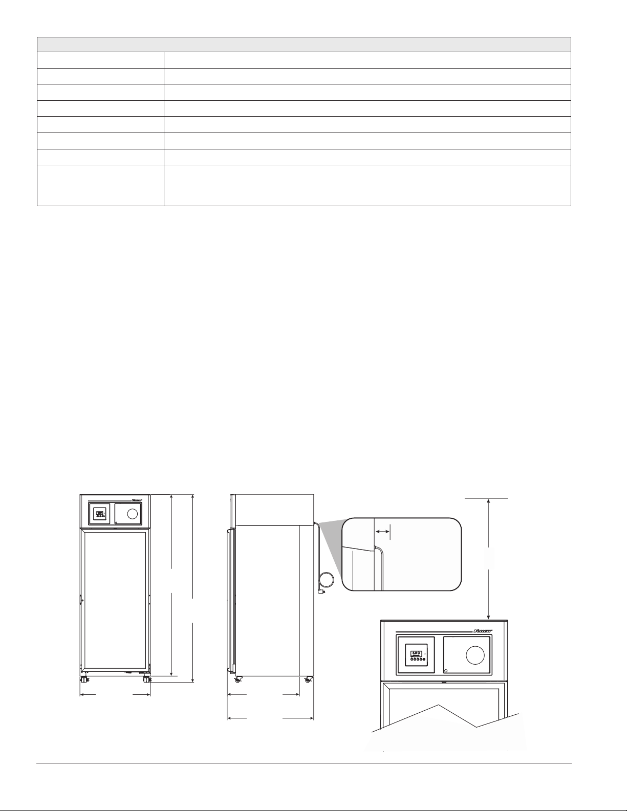
Clearances
The top of the refrigerator must have 10 inches (25.4 cm) of clear space above the refrigerator to ensure proper
ventilation of the refrigeration system.
The back of the refrigerator should have 1 inch (2.5 cm) of clearance to allow for power cord clearance on unit and
an additional 1 inch (2.5 cm) if the unit is to be plugged in directly behind the refrigerator.
Electrical specications
115V, 60Hz, 1 phase
Running load amps: 8.4 amps without heated door; max 9.7 amps with door heater energized 100% (adjustable).
Full load amps (90% maximum continuous current per UL 471 at 40 C): 10.5 amps
Minimum circuit ampacity: 15 amp dedicated circuit
Maximum size of branch circuit overcurrent device: 15 amp dedicated circuit
Refrigeration specications
Refrigerant R134a, 11.4 oz (322g)
Detail drawing
Required Clearances
1.0" (2.5 cm)
for power cord;
76.75"
(195cm)
(202cm)
2.0" (2.5 cm) if
outlet directly
behind unit
79.5"
10.0"
(25.4cm)
29.75"
(76cm)
4 Welcome to Follett 00926170 – REF20/25 LB, PH, BB
REF20
30.5" (78cm)
REF25
36.5" (93cm)
Page 5
Installation
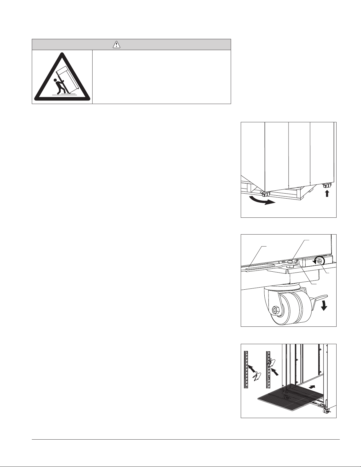
DANGER
• Donottiltanyunitfurtherthan30°offverticalduring
uncrating or installation
• Refrigerationmoduleareacontainsmechanical,moving
parts. Keep hands and arms clear of this area at all
times. If access to this area is required, power to unit
must be disconnected rst.
1. Remove key taped to side of refrigerator cabinet and unlock door.
2. Remove casters from box packed inside refrigerator.
Note: California facilities requiring wall and oor anchors – refer to wall anchor
kit instructions (#00938241) packed with seismic kit before proceeding with
caster installation.
3. Unbolt refrigerator from pallet.
4. Rotate refrigerator on pallet to install casters (Fig. 1.1).
5. Install casters by hand one at a time using channel locks to tighten, until
caster meets against the bottom of cabinet (Fig. 1.2).
6. Peel protective lm from exterior walls of stainless cabinet.
Fig. 1
2
1
Adjust self-closing door
1. Roll refrigerator to desired location and lock as many casters as
possible (Fig 2.1).
2. If the door appears to be sagging, remove the philips screw (Fig. 2.2)
holding the Hold Open Bracket to the Hinge Bracket to gain access to
the Sag Adjustment Screw (Fig. 2.3). Turn the Sag Adjustment Screw to
align the door squarely with the freezer cabinet. When nished, reinstall
the Hold Open Bracket.
3. Check door for closing tension and adjust if necessary. To check closing
tension, open door 1” and turn screw (Fig. 2.4) counterclockwise until
you achieve positive close. (Light will go out) Then, turn another half
turn counterclockwise.
Install shelves (if equipped) and power up
1. If refrigerator is equipped with shelves, remove bag containing shelf
supports and position them in desired locations on each pilaster and
insert shelves (Fig. 3).
2. Plug refrigerator into a 115V 60Hz 15 amp dedicated outlet.
Fig. 2
Fig. 3
1
2
Hold Open
Bracket
4
3
1
2
3
00926170 – REF20/25 LB, PH, BB Installation 5
Page 6
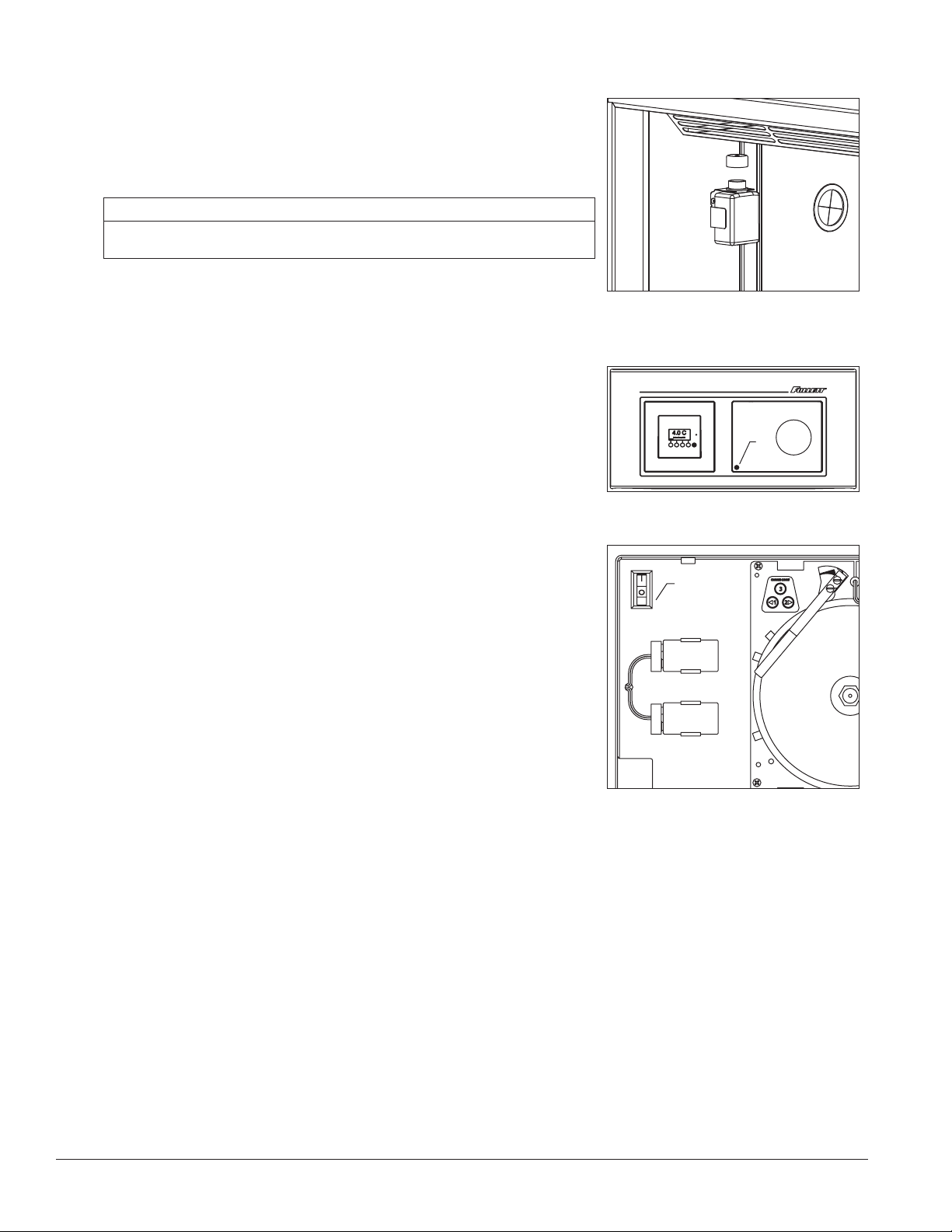
Fill product bottle
1. Remove probe and cap from the top bottle and ll with solution used at
your facility (e.g., 50% glycerine and 50% water) (Fig. 4). Replace cap
and reinsert probe sensor.
2. If equipped with a bottom probe, perform same procedure for bottom
bottle.
ATTENTION INSTALLER
Itisimperativethatthetopprobebottlebelledwithasolutionthatyour
facilityusestoensureproperoperationofunit.
3. Adhere supplied probe wire clips (x4, packaged with manual) to inside
wall leading to the probe bottle.
4. Route probe wire into clips and close the clips.
5. Press lower left corner of front facade door to access power switch
inside (Fig. 5.1).
Fig. 4
Fig. 5
1
Fig. 6
6. Press power switch to turn unit on (Fig. 6.1).
7. Install (2) 9V back-up interface batteries (Fig. 6.2) and (1) 9V chart
recorder back-up battery (if equipped.)
1
2
6 Installation 00926170 – REF20/25 LB, PH, BB
Page 7
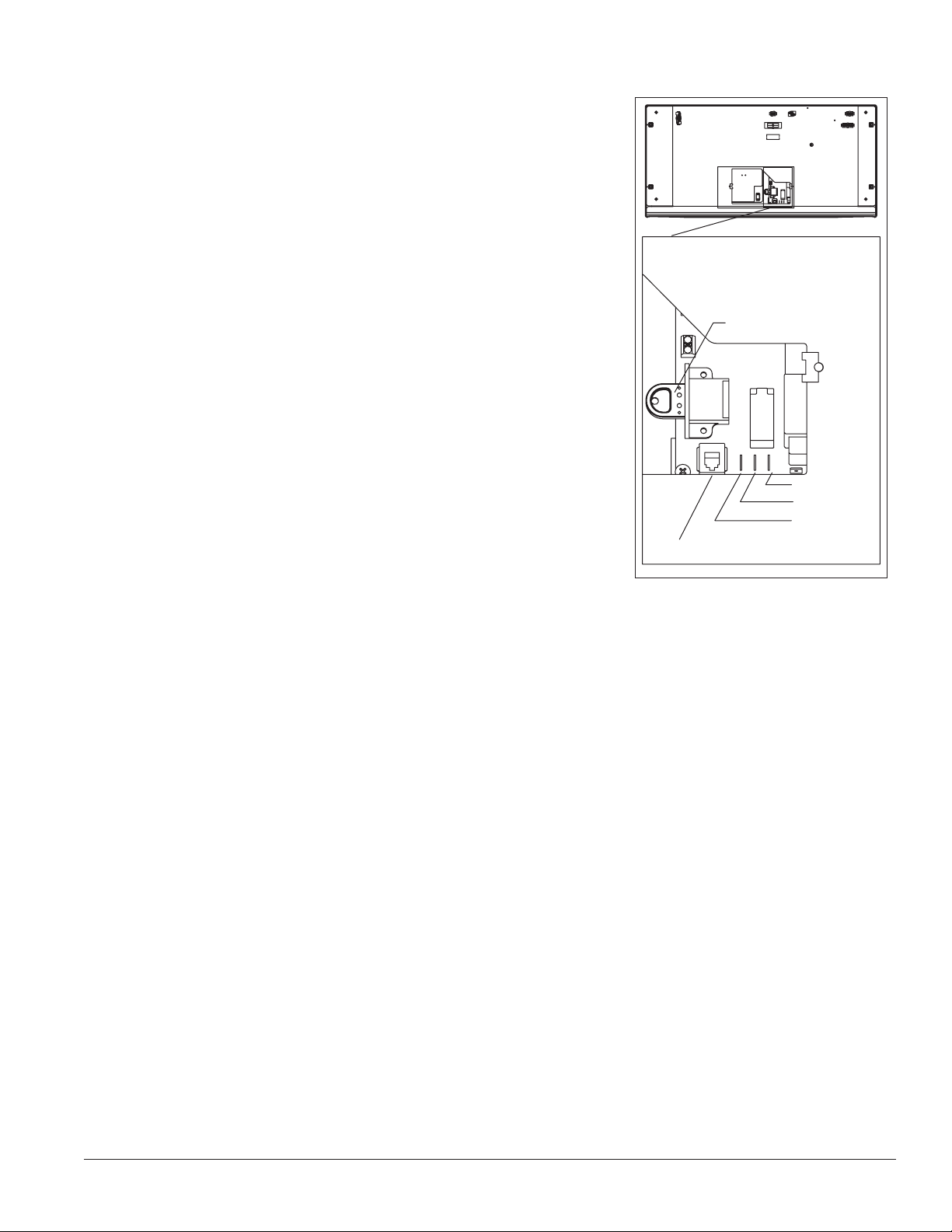
Remote alarm connections (if desired)
Remote communication connections are located on back side of top facade
(Fig.7).
Drycontacts
• Connection to NO or NC contacts provides remote alarming capability
• No temperature data is communicated
RS-485 port
• Connection provides real-time data streaming
– Temperature
– Alarms
– Refrigeration operation
• MODBUS protocol
• Uses 6 pin, 4 conductor RJ11 jack (not supplied)
Fig. 7
Hotkey
Common
N/O
N/C
Alarm Contacts
RS485 Port
00926170 – REF20/25 LB, PH, BB Installation 7
Page 8
Operation
4.0C
Quick setup checklist
• Set time/date
• Change temperature display from factory default Celsius to Fahrenheit (if desired)
• Set high/low temperature alarms
• Select password access (if required)
• Setup chart recorder (if equipped)
• Verify solution is in bottle
DANGER
• Donotextendallofthedrawersorbasketswhen
fullyloadedtoavoidthepossibilityoftherefrigerator
tipping forward
• Refrigerationmoduleareacontainsmechanical,moving
parts. Keep hands and arms clear of this area at all
times. If access to this area is required, power to unit
must be disconnected rst.
Fig. 8
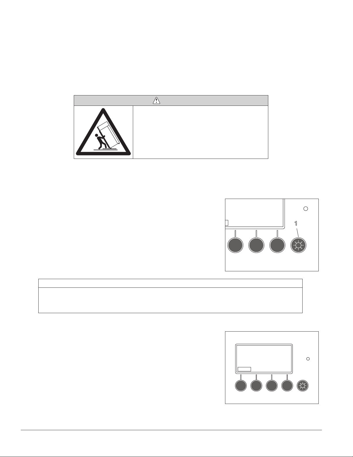
Interior LED lights
Interior lighting of refrigerator with door closed is controlled by light switch
(Fig 8.1) on interface.
Lights will be on whenever door is open regardless of light switch selection.
ATTENTION
• Thetime/datearenotretainedintheeventofapowerinterruptionorifthebatteriesaredead.
• Changebatterieswiththeunitpoweredup.Changeonebatteryatatimetoretaintime/date.Failuretofollowthis
procedure will result in loss of time & date and will not provide accurate time and date stamping for high or low
temperature alarms.
Temp 3.5C
Fig. 9
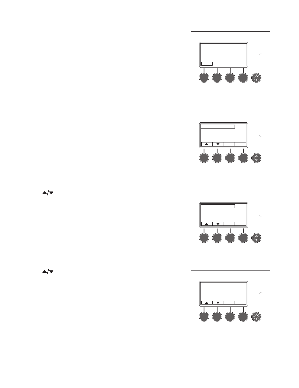
Set time & date
Set time and date for stamping of minimum and maximum temperatures.
1. Press Menu button (Fig. 9).
4.0C
B ottom Temp 3.5C
Menu
1
8 Operation 00926170 – REF20/25 LB, PH, BB
Page 9
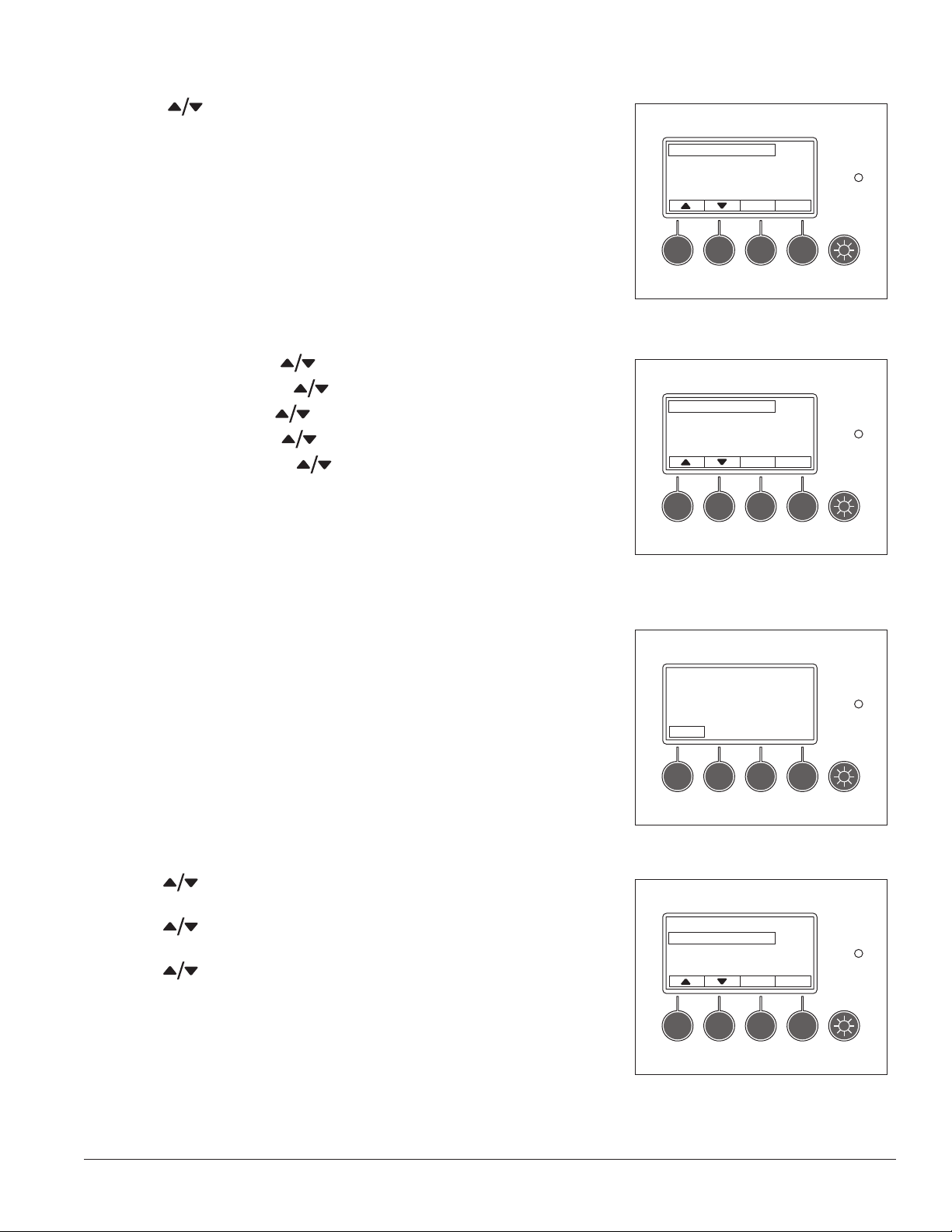
Fig. 10
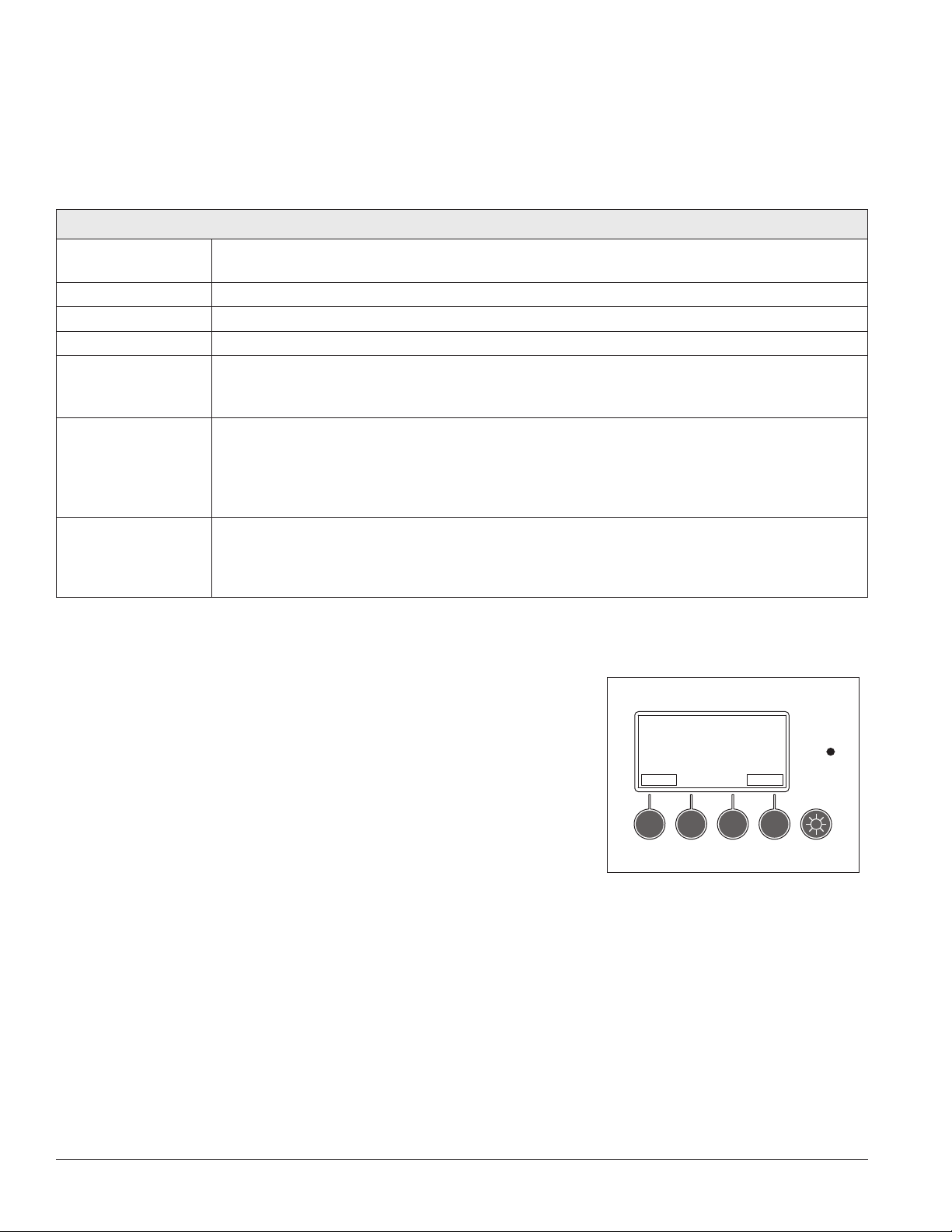
2. Use
to scroll and highlight Set time/date and press Enter to
select (Fig. 10).
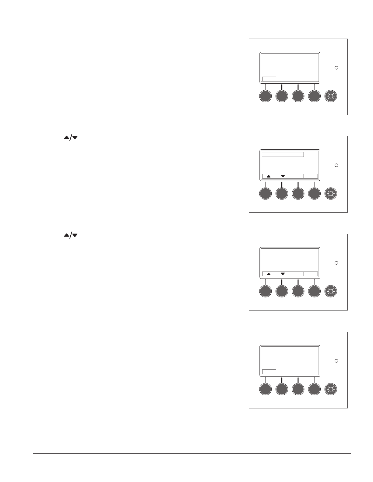
3. Adjust the year using
and press NEXT.
4. Adjust the month using and press NEXT.
5. Adjust the day using and press NEXT.
6. Adjust the hour using
and press NEXT. (24 HR Clock)
7. Adjust the minute using .
8. Press Enter to select values.
9. Press Back until the main temperature display screen is displayed.
S et time/date
S et Alarm V olume
Alarm Silence
Fig. 11
S et year: 2009
2009 10/19 16:13
4.0C
Back Enter
3.4C
Next Enter
Change temperature display to show degrees
Fahrenheit (if desired)
Follett has pre-set the temperature display to read in degrees Celsius. If
degrees Fahrenheit display is preferred:
1. Press Menu button (Fig. 12).
2. Use
select (Fig. 13).
3. Use to scroll and highlight Degrees F/C and press Enter to
select.
4. Use
5. PressBack button until the main temperature display screen is
displayed. Temperature is displayed in degrees F.
to scroll and highlight DisplaySettings and press Enter to
to scroll and highlight F and press Enter to select.
Fig. 12
Menu
Fig. 13
Alarm Settings
Display Settings
M in/Max Te mperatures
Batt = 8.5V OK
4.0C
B ottom Temp 3.5C
4.0C
B ack Enter
00926170 – REF20/25 LB, PH, BB Operation 9
Page 10
High and low alarm setup
The high alarm is set to a default of 40 C (104 F) from the factory. This
default setting is used so that the alarm will not sound while the unit is
pulling down to temperature. The low alarm default setting is 1.0 C (33.8 F).
After the unit has been installed and the system has stabilized
(approximately 1 hr), the high and low alarm set points should be adjusted
to desired settings.
1. Press Menu button (Fig. 14).
2. Alarm Settings will be highlighted. Press Enter to select (Fig. 15).
Fig. 14
4.0C
B ottom Temp 3.5C
Menu
Fig. 15
3. Use
select (Fig. 16).
to scroll and highlight High Alarm Set and press Enter to
Alarm Settings
Display Settings
M in/Max Te mperatures
Batt = 8.5V OK
Fig. 16
High Alarm Set
Low Alarm Set
Fig. 17
4.0C
Back Enter
4.0C
Back Enter
4. Use to change set point and press Enter to accept (Fig. 17).
High Alarm Setpoint 4.0C
40.0C
BackEnter
10 Operation 00926170 – REF20/25 LB, PH, BB
Page 11

Fig. 18
5. Use
to scroll and highlight Low Alarm Set and press Enter to
select (Fig. 18).
6. Use to change set point and press Enter to accept (Fig. 19).
7. Press Back until the main temperature display screen is displayed.
High Alarm Set
Low Alarm Set
Fig. 19
Low Alarm Setpoint 4.0C
1.0C
4.0C
BackEnter
BackEnter
00926170 – REF20/25 LB, PH, BB Operation 11
Page 12
Alarms
The refrigerator has several alarms that will sound an audible and visual alarm. Alarm type is shown on the top
line of the alarm display and multiple alarms will show progressively on the display. A red LED, to the right of the
display, accompanies all alarms.
All active alarms are conveyed to remote alarm relays. Remote alarm relay provides a choice of either a normally
closed (NC) or normally open (NO) contact. It is recommended for use at 24V 1A (relay is rated for 250V 10A).
Alarmdisplayed
Temp Alarm Only top product temperature probe activates this alarm. Bottom product temperature probe,
if installed, is for display reference only.
Top Probe Error Activates with loss of signal from top probe (open or short circuit).
Bottom Probe Error Activates with loss of signal from bottom probe (open or short circuit).
Door Ajar Alarm Activates with door open longer than 1 minute.
AC Power Alarm Activates after 2 min delay with loss of AC power.
Display backlight will turn off to conserve battery life, but pressing any button will brighten
display for 30 seconds.
Low Battery Alarms Display activates when (2) 9V controller back-up batteries decrease to 7.5V (maximum 4 hr
back-up time remaining.) This alarm will audibly chirp every 5 minutes.
Chart recorder – LED ashes green.
All batteries should be changed at same time. Replace batteries one at a time with AC
powerontokeepcorrecttime/date.
Evap Probe Error Activates with loss of signal from refrigeration control evaporator probe (open or short circuit).
Refrigerator goes into a xed on/off cycle until corrected. Default settings are 4 minutes
compressor on time and 8 minutes compressor off time. Cycle on time and off time are
adjustable in faulty probe cycle sub-menu of refrigeration controls menu.
Alarm muting
All audible alarms can be muted for up to 60 minutes in 5 minute
increments by pressing the MUTE button. The desired mute period will
display, and count down, in the window adjacent the MUTE label (Fig.20).
Conditions
Fig. 20
Door Ajar Alarm
4.0C
MENUMUTE
12 Operation 00926170 – REF20/25 LB, PH, BB
15 min
Page 13
Alarm volume selection
Factory default setting is “high”. To change volume of the alarm:
1. Press Menu button (Fig.21).
Fig. 21
4.0C
B ottom Temp 3.5C
Menu
Fig. 22
2. Use
select (Fig.22).
3. Use
select (Fig.23).
4. Press Back until the main temperature display screen is displayed.
to scroll and highlight Set Alarm Volume and press Enter to
to select the volume (high/medium/low) and press Enter to
Set Alarm Volume
Alarm Silence
Fig. 23
B uzzer Volume 4.0C
HIGH
4.0C
Back Enter
BackEnter
Alarm silence
Audible alarming can be turned off through the menu interface:
1. Press Menu button (Fig. 24).
Fig. 24
4.0C
B ottom Temp 3.5C
Menu
00926170 – REF20/25 LB, PH, BB Operation 13
Page 14
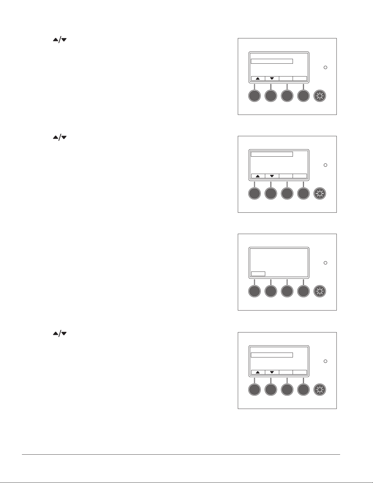
Fig. 25
2. Use
to scroll and highlight Alarm Silence and press Enter to
select (Fig. 25).
3. Use
to select ON or OFF and press Enter to select (Fig. 26).
4. Press Back until main temperature display screen is displayed.
Set Alarm Volume
Alarm Silence
Fig. 26
Audible Alarm 4.0C
ON
4.0C
Back Enter
Back Enter
Password PIN security (default is 3843)
If desired, access to the user selectable features and settings can be
controlled by a password PIN. The refrigerator ships with the password
option turned off. The default password PIN, if the password is turned on, is
3843. This password pin number will always work.
To turn password on/off
1. Press Menu button (Fig.27).
2. Use
Enter to select (Fig.28).
to scroll and highlight Password on/off option and press
Fig. 27
Menu
Fig. 28
Refrigeration Controls
Password on/off
PIN
Set time/date
4.0C
B ottom Temp 3.5C
4.0C
Back Enter
14 Operation 00926170 – REF20/25 LB, PH, BB
Page 15

Fig. 29
3. Use
to choose ON or OFF and press Enter to select (Fig.29).
4. Press Back until the main temperature display screen is displayed.
To make a new password PIN
1. Press Menu button (Fig.30).
Passw ord 4.0C
OFF
Back Enter
Fig. 30
4.0C
B ottom Temp 3.5C
Menu
2. Use
to scroll and highlight PIN and press Enter to select
(Fig.31).
3. Use
to select the rst number of the 4 digit pin. Use the Next
button to move to the next digit, adjust with and repeat for the last
2 digits. Press Enter to select (Fig.32).
4. Press Back until the main temperature display screen is displayed.
Fig. 31
Refrigeration Controls
Password on/off
PIN
Set time/date
Fig. 32
E nter 4 Digit Pin
Digit 1
3843
4.0C
Back Enter
3.3C
Next Enter
00926170 – REF20/25 LB, PH, BB Operation 15
Page 16

Min/max temperature logging
The controller retains maximum and minimum temperatures since last reset
and provides a date and time stamp of when they occurred.
1. Press Menu button (Fig.33).
Fig. 33
4.0C
B ottom Temp 3.5C
Menu
Fig. 34
2. Use
to scroll and highlight Min/Max Temperatures and press
Enter to select (Fig.34).
3. Use
to select the min or max logged temperature (Fig. 35). Press
Enter to reset log.
4. Press Back until the main temperature display screen is displayed.
Alarm Settings
Display Settings
M in/Max Te mperatures
Batt = 8.5V OK
Fig. 35
Min = 2.7C
2009 10/19 12:10
P ress Enter to Reset
4.0C
Back Enter
4.0C
Back Enter
16 Operation 00926170 – REF20/25 LB, PH, BB
Page 17

Probe calibration
Follett refrigerator probes are calibrated to a known standard prior to leaving
the factory. Recalibration can be easily accomplished at any time, if desired:
1. Remove upper temperature probe from probe bottle and completely
submerge into an ice bath.
Note: Ice bath should be densely compacted ice (ake, crushed, nugget, or
cracked) and a little water.
2. Place ice bath with probe in refrigerator and close door.
3. Press Menu button (Fig. 36).
Fig. 36
4.0C
B ottom Temp 3.5C
Menu
Fig. 37
4. Use
hold Enter and
to scroll and highlight Refrigeration Controls, press and
together for 3 seconds (Fig.37).
5. Calibration should be highlighted, press Enter to select (Fig.38).
Refrigeration Controls
Password on/off
PIN
Set time/date
Fig. 38
Calibration
Refrig Setpoint
Differential
H igh Setpoint Limit
4.0C
B ack Enter
4.0C
Back Enter
Fig. 39
6. Cal Top Probe should be highlighted, press Enter to select (Fig.39).
CAL Top Probe
CAL Bottom Probe
4.0C
Back Enter
00926170 – REF20/25 LB, PH, BB Operation 17
Page 18

7. When probe temp stabilizes press Enter button calibrating it to 0.0C
(32 F) (Fig. 40). Wait one minute and press Enter button again to
conrm calibration.
8. Remove probe from ice bath and return to solution-lled probe bottle.
9. Press Back until main temperature display screen is displayed.
10. Repeat steps for bottom probe, if equipped.
ATTENTION
• Bottomtemperatureprobeisonlystandardonbloodbankmodels
• Ifunithasthechartrecorderoption,referto“Chartrecordercalibration”on
page 18.
Fig. 40
S et CAL TEMP W ^/
When Top Probe Stable
P ress Enter
Cal 0.0C i Probe 0.1C
^
4.0C
Back Enter
Chart recorder set up (if so equipped)
The chart recorder is mounted in the front right of the facade behind the
door (Fig. 41). A package of 50 charts that record in C is included with your
refrigerator. If you have changed your display to show temperatures in F,
you will need different charts. Please call Follett at (877) 612-5086 or
+1 (610) 523-9361 to order part number 00967729.
The chart recorder is powered by the controller and has its own battery
back up. An LED provides battery status info: Steady green = battery okay,
Flashing green = low battery or no power to the controller.
Chart recorder calibration
If desired, calibration should be done at the same time as probe calibration
(page 17) by pressing either the left or right arrow keys to correspond with
the calibrated product display temperature.
1. Press Left #1 or Right #2 arrow button (Fig. 41) for 5 seconds until pen
begins to move.
2. Continue to press #1 or #2 button to move pen to record same
temperature as probe.
Changing the chart paper
1. Press and hold #3 button until pen begins to move off chart.
2. Once the pen moves completely off chart, unscrew knob (counter-
clockwise) at center of chart.
3. Remove old chart and place new chart in position so that correct time
coincides with time line groove on recorder.
4. Reinstall knob.
5. Press and hold #3 button for approximately (1) one second until pen
begins to move back onto chart.
6. Make sure pen is marking paper. If not, carefully adjust arm so that
pen makes contact with paper.
Fig. 41
Replacing the pen
1. To replace pen, press and hold the #3 button until pen starts to move
off chart.
2. Once pen has moved completely off chart, carefully lift pen up and
unsnap the “U” clip part to remove pen from metal pen arm.
3. Position new pen on metal pen arm and snap “U” clip underneath pen
around arm to secure.
4. Press and hold #3 button for approximately (1) second until pen begins
to move back onto chart.
5. Make sure pen is marking. If not, carefully adjust arm so that pen
makes contact with paper.
18 Operation 00926170 – REF20/25 LB, PH, BB
Page 19

Removing drawers
1. Pull drawer forward to stop (Fig. 42.1).
2. Lift drawer front to free front rollers from slides (Fig.42.2).
3. Still lifted, pull drawer forward to free back rollers from slides.
Removing slides
1. Push slides all the way back.
2. Swing bottom of slide away from refrigerator wall and lift slide off rollers.
Fig. 42
1
2
00926170 – REF20/25 LB, PH, BB Operation 19
Page 20

Cleaning
Use non chlorine-based cleaners. Cleaners containing chlorine can cause
staining and pitting of the stainless steel.
Disconnect power to unit by turning the power switch off, located on the
upper front facade panel, and removing the power cord from the receptacle.
Interior cleaning
Using a sponge or soft cloth, clean unit with a non-abrasive, nonchlorinated, all-purpose detergent. Note: The left and right air plenums
should be removed to clean them, as well as behind them (Fig.43, 44).
In addition the shelves, baskets, drawers and slides should be cleaned
aswell.
Exterior cleaning
Wipe stainless steel exterior with a soft cloth in the direction of grain as
needed. Stainless steel polish may be used to enhance the nish of the
unit. The glass door and exterior parts may be cleaned with a soft cloth,
window cleaner or other non-abrasive cleaner.
Fig. 43
Fig. 44
20 Cleaning 00926170 – REF20/25 LB, PH, BB
Page 21

Annual cleaning
Removal of dust and other particulates from air intake areas and the
condenser is important for proper operation. Environments with large
amounts of dust may require more frequent cleaning.
1. Disconnect power to unit by turning power switch off (located on upper
front facade panel) and removing power cord from receptacle.
2. The condenser can be accessed from top for cleaning. The side panel
in front of condenser may be completely removed for easier cleaning
by disconnecting facade and removing upper side panel. See “Facade
removal” on page 27 for facade removal instructions.
3. Inspect drain pan for any debris or obstruction in condensate pan
(Fig.45.1).
4. Use a vacuum cleaner with brush attachment to clean condenser,
compressor and related parts.
5. Reinstall upper side panel and facade if removed.
Fig. 45
6. Door maintenance: Place a dab of white lithium grease on top of hold
open arm and keeper on lower hinge assembly of door (Fig.46.1).
1
Fig. 46
1
00926170 – REF20/25 LB, PH, BB Cleaning 21
Page 22

Service
R
The temperature controller and evaporator probe indicate when the refrigeration system is required to turn on
andoff.
The refrigeration system removes heat from the cabinet interior and rejects it to the surrounding room air. When
the evaporator probe temperature reaches 5.0 C (9.0 F) above the controller set point, the probe signals the
controller to turn the refrigeration system on. The normally open controller contacts close and energize the
condenser fan motor and compressor. The compressor uses a current-style starting relay and a starting capacitor
to start the compressor motor.
When the evaporator temperature falls to 5.0 C (9.0 F) below the set point, the probe signals the controller to turn
the refrigeration system off. The controller contacts reopen, which de-energizes the condenser fan motor and the
compressor. The evaporator fan motor runs continuously.
Any accumulated frost on the evaporator coils melts during the off cycle. The condensate drains to a drain
pan mounted in the base of the refrigeration unit. The pan is located under the compressor. The heat from the
compressor, condenser and fan evaporates any condensate in the drain pan as well as providing preliminary
cooling of the high pressure vapor prior to entering the condenser.
Refrigeration system
The REF20/25 series refrigeration system is designed to give many years of trouble-free service. Except for
routine cleaning of the air-cooled condenser and related parts, the refrigeration system requires no service or
maintenance. The system uses a capillary tube metering device and is critically charged. Access ttings are not
provided. Temporary piercing valves are required to work on the refrigeration system. Follett recommends that if
hoses are ever connected to the refrigeration system for service, the refrigerant should be recovered, permanent
access valves should be installed and the system evacuated, and recharged by weighing in the correct refrigerant
charge (refrigerant R134a, 11.4 oz (322g).
Note: Do not charge the system by pressures.
CAPILLARY TUBE
FILTER-DRIER
COMPRESSOR
EVAPORATOR
CONDENSER
HIGH PRESSURE VAPO
HIGH PRESSURE LIQUID
LOW PRESSURE LIQUID
LOW PRESSURE VAPOR
Defrosting
REF20/25 series upright refrigerators do not require manual defrosting. The evaporator defrosts automatically
when the refrigeration unit is in the OFF cycle. The evaporator fan will run continuously.
22 Service 00926170 – REF20/25 LB, PH, BB
Page 23

Controller operation
ATTENTION
BEFORE MAKING ANY CHANGES TO FACTORY-DEFAULT REFRIGERATION
SETTINGS, CONTACT FACTORY.
The controller displays product temperatures in degrees C or F (C is factory default) to 1 decimal point.
The controller is pre-programmed with a 0.5 C (32.9 F) set point which provides a compressor cut-in at 5.5 C
(41.9 F) evaporator coil temperature and cut-out at -4.5 C (23.9 F) evaporator coil temperature. This will correlate
to a product temperature of approximately 4.0 C (39.2 F).
All set points have a 5 C (9.0 F) differential. The 5.0 C (9.0 F) differential means that with a 0.5 C (32.9 F) set
point, for example, the compressor will turn off at -4.5 C (23.9 F) evaporator temperature and turn on when the
evaporator temperature reaches 5.5C (41.9 F).
Product temperature will be displayed on the digital temperature display and chart recorder (if equipped).
Temperature sensor readings
To view temp sensor probe readings:
1. Press Menu button (Fig. 47).
2. Use
to scroll and highlight Refrigeration Controls (Fig.48).
Fig. 47
Menu
Fig. 48
Refrigeration Controls
Password on/off
PIN
Set time/date
4.0C
B ottom Temp 3.5C
4.0C
Back Enter
Fig. 49
3. Press and hold Enter and
together for 3 seconds (Fig.49).
Calibration
Refrig Setpoint
Differential
H igh Setpoint Limit
Back Enter
4.0C
00926170 – REF20/25 LB, PH, BB Service 23
Page 24

Fig. 50
4. Use
to scroll and highlight Temp sensors and press Enter to
select (Fig. 50).
5. The following will be displayed (Fig. 51).
RTD1= Top probe sensor reading
RTD2= Bottom probe sensor reading
(if equipped, otherwise displays default 25 C (77 F))
NTC1= Evaporator Probe reading
NTC2= Displays a default value and is not used
6. Press Back until main temperature display screen is displayed.
FAULTY PROB TIME
T EMP SENSORS
Fig. 51
RTD1= 3.2C
RTD2 = 2.4C
NTC 1 = 3.3C
NTC 2 = -26.8C
4.0C
B ack Enter
Back
Heated door (option) – changing cycle
Factory default for the heated door and fascia heater cycle is set to 50%,
based on a 20 minute cycle (e.g. 50% = 10 minutes off, 10 minutes on).
1. Press Menu button (Fig. 52).
2. Use
to scroll and highlight Refrigeration Controls (Fig.53).
Fig. 52
Menu
Fig. 53
B att = 8.5V OK
Refrigeration Controls
Passw ord on/off
PIN
4.0C
B ottom Temp 3.5C
4.0C
Back Enter
24 Service 00926170 – REF20/25 LB, PH, BB
Page 25

Fig. 54
3. Press and hold Enter and
4. Use
to scroll and highlight DoorHeaterCycle and press Enter
to select (Fig.55).
together for 3 seconds (Fig.54).
Calibration
Refrig Setpoint
Differential
H igh Setpoint Limit
Fig. 55
L ow Setpoint Limit
Door Heater Cycle
Upload To Hotkey
Download from Hotkey
4.0C
Back Enter
4.0C
Back Enter
5. Heater ON cycle is shown as a percentage of 10 minute cycle (Fig. 56).
6. Use
to adjust heater ON cycle percentage and press Enter to
select.
7. Press Back until the main temperature display screen is displayed.
Fig. 56
Heater On Percent 4.0C
50
Back Enter
00926170 – REF20/25 LB, PH, BB Service 25
Page 26

Changing temperature set point
ATTENTION
BEFORE MAKING ANY CHANGES TO FACTORY-DEFAULT REFRIGERATION
SETTINGS, CONTACT FACTORY. FACTORY DEFAULT IS IN DEGREES C. IF USER
HAS CHANGED DISPLAY TO SHOW TEMPERATURE IN DEGREES F, ALL OTHER
TEMPERATURES WILL DISPLAY IN DEGREES F.
The temperature control system is preset by the factory to provide a product
temperature of approximately 4.0 C (39.2 F). If desired, the evaporator
set point temperature can be changed to achieve a different product
temperature. The factory preset 5.0 C (9 F) differential will be maintained
regardless of the controller set point.
EXAMPLE:
If the product temperature is 4.0 C (39.2 F) and the product temperature
needs to be 3.0C (37.3 F). Adjust the refrigeration set point down 1.0 C to
-0.5 C (1.8 F to 31.1 F) from default setting of 0.5C (32.9 F).
Changing the temperature set point:
1. Press Menu button (Fig. 57).
2. Use
to scroll and highlight Refrigeration Controls (Fig. 58).
Fig. 57
Menu
Fig. 58
Refrigeration Controls
Password on/off
PIN
Set time/date
4.0C
B ottom Temp 3.5C
4.0C
Back Enter
3. Press and hold Enter and then
together for 3 seconds.
4. Scroll to Refrig Setpoint, press Enter to select (Fig. 59).
Fig. 59
Calibration
Refrig Setpoint
Differential
H igh Setpoint Limit
4.0C
Back Enter
26 Service 00926170 – REF20/25 LB, PH, BB
Page 27

Fig. 60
5. Use
select (Fig. 60).
6. Press Back until the main temperature display screen is displayed.
to increase or decrease the set point and press Enter to
Facade removal
The facade is removed by loosening the top left and right Phillips screws
on the back of the facade to allow the securing clips to rotate away from
the side panels. The facade can simply pull off of the front by pulling it
out of the bayonet mounts that secure it to the upper left and right panels.
If the facade will be completely removed, the electrical plugs should be
disconnected. The ground wire should be removed from the top right
grounding screw on the cabinet box, not from the facade (Fig.61.1).
CNTRL SETPOINT 4.0C
0.5C
Back Enter
Fig. 61
1
00926170 – REF20/25 LB, PH, BB Service 27
Page 28

Controller replacement
2
CAUTION
• Controllerboardissusceptibletoelectrostaticdischarge.
Extremecareshouldbeexercisedbyusingagrounding
strap when handling and installing control board.
1. Turn off power to unit and unplug.
2. Remove facade and disconnect electrical plugs.
3. Remove screw securing ground screw to refrigerator cabinet
(Fig.62.1). Do not remove ground wire from facade.
4. Place facade face down on at clean surface with bottom of facade
facing you, and remove four screws attaching back panel to facade.
5. Lift and rotate back panel toward you.
6. Take precautions for proper grounding to reduce risk of electrostatic
discharge (ESD) to the controller board.
7. Remove 5 screws securing board to facade (Fig. 62.2).
8. Reposition board away from mounting location and install newboard.
9. Using wiring schematic (attached to inside of removed back panel) as
a guide, remove wires one at a time from back of existing controller
and connect to corresponding terminals on replacement controller.
10. If ribbon cable from the display is not connected, carefully connect to
corresponding location on board (Fig. 62.3).
11. Make sure wiring is secured at same factory locations, so that cover
will not pinch any wires when reinstalled.
12. Flip facade cover back into position on facade and reinstall 4 screws.
13. Place facade on top of refrigerator above compressor.
14. Reconnect electrical plugs and reinstall screw for grounding wire to
grounding location on cabinet.
15. Remount facade to bayonet mounts.
Fig. 62
1
2
3
2
2
2
Reversing the door swing (requires a new door)
REF20/25 units ship standard with a non heated right hinged door. To
change to a left hinged conguration requires a new door. For heated door
options other parts may be required. If the unit has a heated door option
consult technical service by calling (877) 612-5086 or +1 (610) 252-7301.
Heated doors
Heated doors are factory installed. An unheated door cannot be retrotted to
a heated door in the eld.
28 Service 00926170 – REF20/25 LB, PH, BB
Page 29

Door gasket replacement
1. Remove existing gasket from mounting track (Fig. 63).
2. Verify mounting track is free of any remaining gasket material.
3. Align new gasket with mounting track and press rmly in place.
4. Open and close door, checking for proper gasket seal without pinching
against refrigerator.
Fig. 63
Slide-out unit cooler
Follett’s slide-out refrigeration system allows technicians to remove the
entire unit from the refrigerator top.
1. If necessary remove facade and upper side panels.
2. Remove four bolts securing unit cooler to refrigerator top (Fig.64).
3. Gently lift off cooler.
Fig. 64
00926170 – REF20/25 LB, PH, BB Service 29
Page 30

Wiring diagram (After Serial Number E15526)
115 VAC
L1
1φ, 60 Hz
BLK
010203
K8
ON/OFF
20A
16
K6
07
BACKUP
9 V
DOOR SW
PROBE
BOTTOM
PROBE
(RTD2)
EVAP
PROBE
(NTC1)
04
17
K7
09
+
MAGNET
TOP
(RTD1)
BLK
BLK
BLK
+
RED
RED
WHT
RED
RED
WHT
COMPRESSOR
O/L
RED
K8
J30
+
RED
-
BLK
WHT
WHT
+
GND
+
GND
21
J28
22
J23
J20
(CSIR)
J26
J27
C
12 VDC
PCB
+
COND FAN
R
S
EVAP FAN
T1
12 VDC
K6
K2
K2
START RELAY
J36
0-5 VDC
J24
OUT
TXD +
J19
TXD -
GND
J1
K1
-
K7
K5
K1
SR
N/C
N/C
GND
N
WHT
GRN/YEL
SR
RED
WHT
216-259 μF
220 VAC
05
06
18
32
INTERIOR
LINER
39
38
37
+
19
TO CHART
RECORDER
RJ11
6P/4C
REMOTE
ALARM
1 A 24 V
LCD
23
RED
RS485
HOT KEY
I/O PORT
24
-
5V
42
30
K5
08
801 Church Lane
Easton, PA 18040 USA
For service call:
Toll free (877) 612-5086 or
10
25
+
24VDC
POWER
26
SUPPLY
L
DOOR/FASCIA
11
60
12
63
BLK
HEATERS
70
41
62
+
BACKUP
9 V
WHT
20
_
27
N
36
61
64
CHART RECORDER
1+4
+
RED
BLK
12 VDC
-
BLK
76
14
15
2+5
0-5 VDC
31
13
73
+
RED
-
IN
BLK
FROM
PCB
30 Service 00926170 – REF20/25 LB, PH, BB
Page 31

Wiring diagram (After Serial Number E15526)
COND FAN
SR
COMP
R
S
EVAP FAN
COOLER UNIT 00918151
DOOR
HEATER
FASCIA
HEATER
100w45w
CABINETCABINET
BOTTOMTOP
(RTD2)
PROBE
EVAPORATOR
t°
PROBE
(NTC1)
t°
1 2
21
22
G + -G + -
RED
RED
WHT
WHT
RED
RED
RED
J26 J27 J29 J28 J20 J24
(NTC2)
Control PC Board
PROBE
32
04
2 4
K8
1 3
01
09
O/L
C
NEMANEMA
60
ML-2RML-2P
62
61
63
64
24
23
30
04
1
40
2
3
4
5
11
1
41
2
14
3
12
4
15
5
19
1
20
2
02
06
17
18
09
07
10
13
17
16
10
08
19
25
BAT2 9V
BAT1 9V
42
BACKING
PLATE
J19
J6
NC
J42
NO
J4
C
J18
J17
J15
J12
J8
J5
J10
J13
J14
J11
J7
J9
(RTD1)
+
+
J1
REMOTE
K1
K7
EVAP FAN
K6
DOOR HTR
K5
LEDS
K2
t°
J23
COOLER
SWITCH
BAT3 9V
Recorder
+-GG+-
DOOR
NC
Chart
Signal
+
J3
+
5-15P
31
INTERIOR LIGHTING
24 VDC 1 A
15Amp
-V +V
24 VDC
POWER
36 W
SUPPLY
CL II
N L
120Vac
L1
1
01
GND
2
39
N
3
05
02
J40
07
ON/OFF SWITCH
J31J32J33J34
J30
32
26
08
03
16
27
J35
J37J38J39J41
J36
18
05 & 06
13
J21 J22
70
73
72
75
74
5 4 2 1
Chart
Recorder
Transformer
71
76
Component Details
Compressor amperage
RLA - 7.6A, LRA - 44.5A
Compressor winding resistances
C-S (5.2Ω - 5.9Ω), C-R (1.2Ω - 1.3Ω)
Evaporator fan motor amperage
FLA - 0.22A
Condenser fan motor amperage
FLA - 0.46A
00926170 – REF20/25 LB, PH, BB Component Details 31
Page 32

Wiring diagram (Serial Numbers D61742— E15526)
115 VAC
L1
1φ, 60 Hz
BLK
010203
K8
ON/OFF
20A
16
K6
07
BACKUP
9 V
DOOR SW
PROBE
BOTTOM
PROBE
(RTD2)
EVAP
PROBE
(NTC1)
04
17
K7
09
+
MAGNET
TOP
(RTD1)
BLK
+
BLK
BLK
RED
RED
WHT
RED
RED
WHT
COMPRESSOR
O/L
RED
K8
J30
+
RED
-
BLK
WHT
J20
WHT
+
GND
+
GND
21
J28
22
J23
(CSIR)
J26
J27
COND FAN
C
12 VDC
PCB
+
R
S
EVAP FAN
T1
12 VDC
K6
K2
K2
START RELAY
J36
0-5 VDC
J24
OUT
TXD +
J19
TXD -
GND
J1
K1
-
K7
K5
K1
SR
N/C
N/C
GND
N
WHT
GRN/YEL
SR
RED
WHT
216-259 μF
220 VAC
05
06
18
32
INTERIOR
LINER
39
38
37
+
19
TO CHART
RECORDER
RJ11
6P/4C
REMOTE
ALARM
1 A 24 V
LCD
23
RED
RS485
HOT KEY
I/O PORT
24
-
5V
42
20
25
+
24VDC
POWER
26
SUPPLY
L
K5
11
08
10
60
12
63
DOOR/FASCIA
HEATERS
BLK
70
41
62
+
BACKUP
9 V
WHT
RED
BLK
30
_
BLK
27
N
36
61
64
CHART RECORDER
1+4
+
12 VDC
-
76
14
15
2+5
0-5 VDC
31
13
73
+
RED
-
IN
BLK
FROM
PCB
32 Component Details 00926170 – REF20/25 LB, PH, BB
Page 33

Wiring diagram (Serial Numbers D61742— E15526)
COND FAN
COMP
SR
R
C
S
EVAP FAN
COOLER UNIT 00918151
DOOR
HEATER
FASCIA
HEATER
100w45w
CABINETCABINET
BOTTOMTOP
(RTD2)
PROBE
t°
EVAPORATOR
PROBE
(NTC1)
t°
1 2
21
22
G + -G + -
RED
RED
WHT
WHT
RED
RED
RED
J26 J27 J29 J28 J20 J24
(NTC2)
Control PC Board
NEUTRAL
PROBE
32
04
2 4
K8
1 3
01
09
O/L
04
1
40
2
3
4
5
NEMANEMA
60
ML-2RML-2P
62
61
63
64
24
23
30
11
1
41
2
14
3
12
4
15
5
19
1
20
2
02
06
17
18
09
07
10
13
17
16
10
08
19
25
BAT2 9V
BAT1 9V
42
BACKING
PLATE
J19
J6
NC
J42
NO
J4
C
J18
J17
J15
J12
J8
J5
J10
J13
J14
J11
J7
J9
(RTD1)
+
+
J1
REMOTE
K1
K7
EVAP FAN
K6
DOOR HTR
K5
LEDS
K2
HOT
t°
J23
COOLER
SWITCH
BAT3 9V
Recorder
+-GG+-
DOOR
NC
Chart
Signal
J3
+
+
5-15P
31
INTERIOR LIGHTING
24 VDC 1 A
120Vac
15Amp
24 VDC
36 W
CL II
-V +V
POWER
SUPPLY
N L
L1
1
01
GND
2
39
N
3
05
02
J40
ON/OFF SWITCH
J31J32J33J34
J30
32
26
08
07
03
16
27
J35
J37J38J39J41
J36
18
05 & 06
13
J21 J22
70
73
72
75
74
5 4 2 1
Chart
Recorder
Transformer
71
76
Component Details
Compressor amperage
RLA - 7.6A, LRA - 44.5A
Compressor winding resistances
C-S (5.2Ω - 5.9Ω), C-R (1.2Ω - 1.3Ω)
Evaporator fan motor amperage
FLA - 0.22A
Condenser fan motor amperage
FLA - 0.46A
00926170 – REF20/25 LB, PH, BB Component Details 33
Page 34

Wiring diagram (Before Serial Number D61742)
115 VAC
L1
1 , 60 Hz
BLK
010203
K7
ON/OFF
20A
16
K6
BACKUP
9 V
MAGNET
DOOR SW
PROBE
BOTTOM
PROBE
EVAP
PROBE
(NTC)
4
17
TOP
(RTD)
(RTD)
GND
N
COND FAN
WHT
GRN/YEL
05
39
3837
BLK
COMPRESSOR
(CSIR)
O/L
START RELAY
R
C
SR
SR
WHT
216-259
220 VAC
07
µF
S
EVAP FAN
0-5 VDC
OUT
TXD +
TXD -
J1
K1
J36
N/C
GND
N/C
-
RED
+
TO CHART
RECORDER
-
5V
RJ11
REMOTE
ALARM
1 A 24 V
LCD
RS485
HOT KEY
I/O PORT
6P/4C
RED
J26
J27
T1
12 VDC
PCB
12 VDC
J24
J19
J30
+
BLK
BLK
+
RED
RED
WHT
RED
RED
WHT
RED
BLK
WHT
WHT
J23
-
J20
+
GND
+
GND
21
J28
22
+
+
K7
18
INTERIOR
LINER
K6
K5
K1
K2
24
K2
23
19
RED
42
20
25
+
24VDC
POWER
26
SUPPLY
L
K5
11
08
10
60
63
12
DOOR/FASCIA
HEATERS
BLK
70
WHT
41
62
RED
+
BLK
CHART RECORDER
BACKUP
30
_
BLK
27
N
36
61
64
1+4
+
12 VDC
-
76
14
15
2+5
0-5 VDC
31
13
73
+
RED
-
IN
BLK
FROM
PCB
34 Component Details 00926170 – REF20/25 LB, PH, BB
Page 35

Wiring diagram (Before Serial Number D61742)
COND FAN
COMP
SR
R
O/L
S
EVAP FAN
C
1
40
2
3
4
5
04
07
17
18
42
BAT2 9V
BAT1 9V
BACKING
+
+
PLATE
(RTD1)
PROBE
t°
(RTD2)
RED
WHT
RED
RED
CABINETCABINET
BOTTOMTOP
PROBE
G+ -G+ -
G+ -G+ -
WHT
t°
RED
RED
(NTC2)
EVAPORATOR
PROBE
(NTC1)
t°
21
21
22
DOOR
SWITCH
NC
BAT3 9V
Chart
Recorder
Signal
J3
+
+
DOOR
HEATER
FASCIA
HEATER
5-15P
100w
45w
24
31
INTERIOR LIGHTING
(+24VDC 35W)
J40
K1
K7
K6
K3
K4
K5
K2
J1
08
REMOTE
COOLER
EVAP FAN
PAN HTR
DEFROST HTR
DOOR HTR
LEDS
J31J32J33J34
16
0302
J23
J26J27 J29J28 J20J24
Control PC Board
J37J38J39J41
J30
26
27
18
J36
07
05
J35
13
J19
J6
NC
J42
NO
J4
04
NEMANEMA
60
ML-2RML-2P
62
61
63
64
23
30
120Vac
15Amp
11
1
2
3
4
5
1
20
2
36
L1
1
GND
2
N
3
41
14
12
15
19
-V +V
POWER
SUPPLY
NL
01
39
05
10
13
25
13
01
02
17
16
10
18
07
C
J18
J17
J15
J12
J8
J5
J13
J10
J14
J11
J7
J9
ON/OFF SWITCH
+-GG+-
J21J22
70
73
72
75
74
54 21
Chart
Recorder
Transformer
71
76
Component Details
Compressor amperage
RLA - 7.6A, LRA - 44.5A
Compressor winding resistances
C-S (5.2Ω - 5.9Ω), C-R (1.2Ω - 1.3Ω)
Evaporator fan motor amperage
FLA - 0.22A
Condenser fan motor amperage
FLA - 0.46A
00926170 – REF20/25 LB, PH, BB Component Details 35
Page 36

Troubleshooting
Before calling for service
1. Check that unit is plugged in.
2. Test outlet with another appliance to verify power.
Problem Indicators Corrective Action
1. Power switch faulty or in OFF position;
loose connection.
Refrigerator does
not operate (no
components run).
Compressor does not
run.
Evaporator fan motor
does not run.
Refrigerator does not
shutoff.
Refrigerator does not
maintain temperature
(all components run).
2. Refrigerator not plugged in. 2. Connect plug.
3. No power at outlet. 3. Restore power.
4. Temp controller not energizing
components.
5. Probe not sensing cut-in temperature. 5. Replace controller and/or probe.
1. Thermal overload open or defective. 1. Allow to cool or replace.
2. Capacitor and/or relay defective. 2. Replace as required.
3. Compressor defective. 3. Replace compressor.
1. Defective fan motor. 1. Replace fan motor
1. Controller not sensing cut of
temperature.
2. Controller keeping refrigeration system
energized.
1. Condenser or evaporator coil needs
cleaning.
2. Door not closing. 2. Adjust door closure per page 5.
3. Excessively high ambient. 3. Maximum recommended ambient is 100 F.
4. Refrigerant leak. 4. Locate and repair leak.
5. Incorrect refrigerant charge. 5. Recover, evacuate and weigh in correct
6. Plugged capillary tube. 6. Replace capillary tube.
7. Inefficient compressor. 7. Consult technical service.
8. Faulty door gasket. 8. Replace door gasket
1. Turn power switch to ON position; check
switch and connections.
4. Check controller contact terminals for
power. Replace controller if needed.
1. Replace controller and/or evaporator
(NTC1) probe.
2. Replace controller.
1. Clean coils as needed.
charge.
If problems persist after following this basic troubleshooting guide, call Follett’s technical service group at
(877) 612-5086 or +1 (610) 252-7301.
36 Troubleshooting 00926170 – REF20/25 LB, PH, BB
Page 37

Appendix
Control key functions
MENU
Enter main menu
Back
Return to prior
Buttons to select
screen options
Scroll up
Scroll down
ENTER
MUTE
Select
Mutes alarm
C abinet light ON/OFF
Alarm light
Menu Navigation table
Main Menu Sub menu Default setting Range Notes
If password is ON,
enter 4 digit pin
Alarm settings High alarm set 40 C (104 F) 40 to -40 C
Low alarm set 1.0 C (33.8 F) 40 to -40 C
Display settings Show bottom temp NO YES/NO
Display inverse YES YES/NO Reverse light lettering with dark background
Degrees F/C C F or C Displays temperatures in F or C
Min/Max temp Records min/max temperature and time of top probe. Up/
Batt = _V OK Shows status of (2) 9V batteries.
Refrigeration
controls (press
and hold down-
arrow and ENTER
for 3 seconds)
Password ON/OFF OFF ON/OFF
PIN 3843 0000-9999 Any four digit PIN can be stored beside the permanent
Set Time/Date Adjust with up/down arrow, next moves to next digit, press
Set alarm volume High High/Med/Low Buzzer volume
Alarm silence ON ON/OFF Audible alarm
Calibration Cal top probe Adjust with up/down arrow, press enter to set
Refrig. setpoint 0.5 C (32.9 F) 40 to -40 C
Differential 5.0 C (9.0 F) 3.0 to 6 C
High setpoint limit 5.0 C (41.0 F) 40 to -40 C
Low setpoint limit -1.5 C (29.3 F) 40 to -40 C
Door heater cycle 0% 0 to 100% Heater on percent (50% for heated door option)
On time 4 min 2-14 min Compressor on time
Off time 8 min 2-14 min Compressor off time
Temp sensors Displays probe temperatures
3843 0000-9999 Adjust with up/down arrow, next moves to next digit, press
enter to set
Default is set high to not alarm on initial cool down
(104 to -40F)
(104 to -40F)
down arrow displays min/max. Enter to reset.
Cal bottom probe Adjust with up/down arrow, press enter to set
(104 to -40F)
(5.4 to 10.8 F)
(104 to -40F)
(104 to -40F)
factory default. Adjust with up/down arrow, next moves to
next digit, press enter to set.
enter to set
00926170 – REF20/25 LB, PH, BB Appendix 37
Page 38

Replacement parts
Unit cooler
6
1
7
8
3
4
5
2
Reference Description Part #
Not shown Gasket, unit cooler 00912980
Not shown Probe, evap, NTC 00940148
1 Unit cooler with mounting bolts and gasket 00939785
2 Evaporator fan motor with blade 00945311
3 Condenser fan motor with blade 01179704
Not shown Cap tube and drier 00945378
4 Compressor with start capacitor, relay and overload 01096015
5 Start capacitor 01077734
Not shown Start relay 00945360
Not shown Compressor overload 00945386
6 Evaporator 00945766
7 Condenser 00945774
8 Fan guard, condenser 00945782
Not shown Cord and plug kit 00939900
38 Replacement parts 00926170 – REF20/25 LB, PH, BB
Page 39

Cabinet
7
8
6
2
3
9
5
9
1
4
Reference Description Part #
1 Caster, swivel with brake 00187674
2 Bracket, bottle, 125ML 00171132
3 Drawer, assembly, REF25 00939652
3 Drawer, assembly, REF20 00939660
4 Slide, drawer, REF25 (set of 2) 00193045
4 Slide, drawer, REF20 (set of 2) 00188367
5 Bottle with gasket 01015 8 17
Not shown Basket, assembly, REF25 00939710
Not shown Basket, assembly, REF20 00939728
6 Shelf, REF25 (with supports) 01015841
6 Shelf, REF20 (with supports) 01015858
7 Pilaster 00901173
Not shown Pilaster, screws 00902213
8 Support, shelf 00156240
Not shown Air panel 00901561
Not shown Probe, RTD, top 00918839
Not shown Probe, RTD, NIST calibrated, top 01101096
Not shown Probe, RTD, bottom 00988055
Not shown Probe, RTD, NIST calibrated, bottom 0110110 4
Not shown Plug, RTD probe 00919274
Not shown Panel jack, female 00918847
9 Cover, thermal break (4 pieces) 00922997
Not shown Channel, probe 01004159
Not shown Bushing, probe channel (LB and PH require 2, BB requires 3) 001111 0 4
Not shown LED, light strip 00980912
Not shown Wire clip, probe 00919910
Not shown Glycerine (1 pint) 00959296
Not shown LEDs (2), MOV and instructions 01049709
00926170 – REF20/25 LB, PH, BB Replacement parts 39
Page 40

Facade
1
13
6
12
11
2
5
3
9
8
10
4
7
Reference Description Part #
1 Chart recorder 00906198
2 LED power supply 00939801
3 Controller (for serial numbers above D61742) 00918169
3 Controller (for serial numbers below D61742) 01009729
Not shown Kit, door switch 00939959
4 Male, bayonet (strike, snap) 00179549
5 Facade, locking clip 00931501
6 Complete facade assembly with chart recorder 01007293
6 Complete facade assembly without chart recorder 01007301
7 Facade, cover, with chart recorder 00940130
Not shown Facade, cover, without chart recorder 00940155
8 Pens, chart recorder, red (box of 6) 00918813
Not shown Charts (box of 50) in degrees C 00918821
Not shown Charts (box of 50) in degrees F 00967729
9 Battery, 9V 00112177
10 Latch, touch 00901165
11 Shell, upper side REF25 00940098
11 Shell, upper side REF20 00925933
Not shown Top ventilated cover 00991760
12 Control relay, compressor (for serial numbers above D61742) 00980482
Not shown Bottom probe, resistor 01041342
Not shown MOV assembly 01042258
Not shown Back support 00991695
13 Female, fastener 00179556
40 Replacement parts 00926170 – REF20/25 LB, PH, BB
Page 41

Door assembly
13
2
Reference Description Part #
Not shown Door gasket 00945345
Not shown Left-hand, non-heated door 00939876
1 Right-hand, non-heated door 00939884
2 Right-hand hinges and hardware with black colored hold open bracket 00996579
Not shown Left-hand hinges and hardware with black colored hold open bracket 00996587
Not shown Left-hand hinges and hardware with steel colored hold open bracket 00939918
Not shown Right-hand hinges and hardware with steel colored hold open bracket 00939926
Not shown Door magnet kit 00939967
Not shown Bracket, strike 00939983
Not shown Left-hand heated door 00939991
Not shown Right-hand heated door 00940007
Not shown Key, door 00945436
3 Lock, door 00945444
Not shown Soft port kit 00940122
Not shown Wall bracket kit, seismic anchoring 00927194
Not shown Kit, Pyxis bracket 00927202
Not shown Kit, Omnicell 00966432
00926170 – REF20/25 LB, PH, BB Replacement parts 41
Page 42

42 Replacement parts 00926170 – REF20/25 LB, PH, BB
Page 43

00926170 – REF20/25 LB, PH, BB Replacement parts 43
Page 44

801 Church Lane • Easton, PA 18040, USA
Toll free (877) 612-5086 • +1 (610) 252-7301
www.follettice.com
00926170R09
© Follett LLC 6/17
 Loading...